service manual: venus-c2/v-c2 (d014/d015), aficio...
TRANSCRIPT

PCU
Charge Units
The procedure for removing the drum charge components in the K PCU and YMC PCUs is different.
• The YMC PCUs use a charge roller to charge the OPC drum.
• The K PCU uses a charge wire unit to charge the OPC drum.
Preparation
1. Remove the PCU stand from the bottom of the machine.
2. Remove the PCU from the machine.
3. Set the PCU on the PCU stand.
• The PCU stands for the D014/D015 and B132/B181/B200 copiers are different. Be sure touse the PCU stand for the D014/D015. If you use the PCU stand for the B132/B181/B200,this could damage the exposed drum on the bottom of the PCU.
PCU
289
3

Charge Roller Unit: YMC PCUs
1. Remove the charge roller unit [A] ( x2).
This unit contains the charge roller and charge roller cleaning roller.
• If you need to replace a charge roller unit, be sure to replace the C, M, Y charge roller unitstogether.
Charge Wire Unit: K PCU
3. Replacement and Adjustment
290
3

1. Remove:
[A] Cover ( x2)
[B] Charge wire unit
The charge corona wire and charge corona wire cleaning mechanism comprise the charge wire unit.The unit is replaced as you see it above (no further disassembly is required).
Separating Drum/Cleaning Unit, Removing the OPC Drum
Before doing maintenance on a PCU:
• Separate the development unit and cleaning unit.
• Remove the drum and cover it with a sheet of clean paper to protect it from light.
1. Remove:
• PCU
• Charge roller unit (or charge wire unit for K PCU)
2. At the front, remove:
[A] Small lock plate ( x1)
[B] Large lock plate ( x2)
3. At the rear, remove:
[C] Small lock plate ( x1)
[D] Brown coupling
[E] Large lock plate ( x3)
PCU
291
3

4. Separate the drum unit [F] from the development unit [G].
5. Remove the drum [A] from the development unit.
6. Wrap the drum in a sheet of clean white paper to protect it from light.
Reinstallation of the Drum
This procedure is the same for the YMC PCUs and the K PCU.
• Always dust the surface of a new drum before you install it.
• If you have removed the drum and intend to re-install the same drum, the surface of this drum shouldbe dusted as well.
Before you begin…
• Make sure that you have the correct type of dusting powder for the drum. Use only Lubricant PowderB1329700 (specially designed for this machine).
• Never use Setting Powder 54429101. This powder can damage the drum and charge roller.
• Do not use the yellow toner of the D014/D015 copier because it contains developer that coulddamage the drum and ITB.
To dust the drum:
1. Spread a small amount of lubricant powder on a clean sheet of paper.
2. Dip a clean, dry cloth into the lubricant powder.
3. Replacement and Adjustment
292
3

3. Dust the surface of the drum with the cloth until the entire surface is covered.
4. When you reinstall the drum:
Reinstall the front end of the drum first.
Never rotate the drum manually after reinstalling it.
5. You must do the appropriate SP codes to prevent a fatal error, depending on whether you havereplaced only the drum or the drum/cleaning blade. For more details, refer to the SP Codes AfterReplacement table.
PCU Blades and Rollers
This section describes how to replace these parts of the drum cleaning unit:
• Lubricant bar
• Lubricant blade
• Lubricant brush roller
• Drum cleaning blade
• Collection coil
The procedures described below apply to both a YMC PCU and K PCU.
• However, the lubricant bar unit is not the same for both units. The lubricant bar unit is marked "K" forthe black PCU.
PCU
293
3

• If you replace a cleaning blade, apply lubricant powder to that cleaning blade and to the drum.
Lubricant Bar and Lubricant Blade
Preparation
• Remove the PCU
• Separate the development unit and drum unit.
• Remove the drum, cover it with a piece of clean paper, and set it aside.
1. Remove the lubricant blade ( x2).
2. Remove the screws from the ends of the lubricant bar unit [A] ( x2).
3. Remove:
3. Replacement and Adjustment
294
3

[A] Charger roller unit holder (x2)
[B] Bracket with sponge seal
[C] Lubricant bar unit cover (x2)
To remove the old lubricant bar:
1. At the center [A], disconnect springs from the post.
2. Disconnect the rear spring [B] from the rear bar support, then remove the support [C] from its post.
3. Disconnect the front spring [D] from the front bar supports, then remove the support [E] from its post.
4. Remove the lubricant bar [F] and replace it with a new one.
• The lubricant bars of the K PCU and YMC PCUs are identical. The same type of lubricant barcan be installed in either type of PCU.
• The springs of the lubricant bar units are not interchangeable. The springs of the CMY lubricantbar unit are brown and stronger than the springs of the K lubricant bar unit (the K lubricant barsprings are black).
PCU
295
3

Lubricant Brush Roller
1. Remove:
[A] Gears ( x2, Gears x5).
2. Remove:
[A] Shaft lock plate ( x1)
[B] Lubricant brush roller (Coupling x1, x1)
3. Replacement and Adjustment
296
3

Drum Cleaning Blade
1. Remove:
[A] Drum cleaning blade ( x2).
After Replacement
Do the procedure below after replacing the lubricant brush roller.
1. Place a sheet of clean paper [A] on a flat surface.
2. Pour a small amount of Lubricant Powder (B1329700) [B] from its bag onto the paper.
3. Pour a small amount of yellow toner (B132/B181/B200) [C] from its toner cartridge. (Use the tip ofa pen or a pointed tool to depress plug [D] to release the yellow toner.)
PCU
297
3

• You must use yellow toner for the B132/B181/B200.
• Do not use D014/D105 yellow toner because it contains developer that could damage thedrum and ITB.
• The correct EDP codes for the yellow toner are listed in the table under Required Materials inSection 2.
4. User your finger to mix evenly the lubricant powder and yellow toner on the paper.
5. Use your finger to apply the lubricant-toner mix to the cleaning brush at [A] while rotating the gear[B] in the direction shown by the arrow.
• You must rotate the gear in the direction shown above.
6. After reinstalling the unit in the machine, do the forced MUSIC adjustment with SP 2111 001.
Developer Replacement
The developer replacement procedure is the same for the YMC PCUs and the K PCU.
Preparation
1. Spread some paper on a flat surface to hold developer that will be dumped from the developmentunit.
3. Replacement and Adjustment
298
3

2. Remove:
[A] PCU stand from bottom of the machine
[B] Jig
[C] Brown coupling
• The PCU stands for the D014/D015 and B132/B181/B200 copiers are different. Be sure touse the PCU stand for the D014/D015. If you use the PCU stand for the B132/B181/B200,this could damage the exposed drum on the bottom of the PCU.
3. Remove the metal jig [B] and brown coupling [C] from the bottom of the PCU stand.
4. Set the PCU stand on a flat surface.
5. Remove:
• Toner hopper
• Faceplate
• PCU
PCU
299
3

6. Position the front and rear of the PCU so that it matches the F (front) and R (rear) markings on the PCUstand.
7. Set the PCU on the stand.
• The front-rear alignment aligns the shape of the stand with the contours of the PCU bottom.
• This also protects the exposed drum on the bottom of the PCU during servicing.
Removing the old developer
Preparation
• Separate the drum unit and development unit.
• Cover the drum with a sheet of clean paper and set it aside.
1. Remove:
3. Replacement and Adjustment
300
3
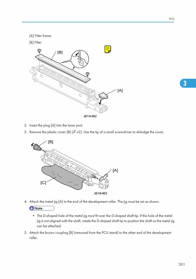
[A] Filter frame
[B] Filter
2. Insert the plug [A] into the toner port.
3. Remove the plastic cover [B] ( x2). Use the tip of a small screwdriver to dislodge the cover.
4. Attach the metal jig [A] to the end of the development roller. The jig must be set as shown.
• The D-shaped hole of the metal jig must fit over the D-shaped shaft tip. If the hole of the metaljig is not aligned with the shaft, rotate the D-shaped shaft tip to position the shaft so the metal jigcan be attached.
5. Attach the brown coupling [B] (removed from the PCU stand) to the other end of the developmentroller.
PCU
301
3

• Use the brown coupling provided with the PCU stand. Using the coupling of the PCU could breakit or wear it out.
6. Rotate the brown coupling in the direction shown above so the developer [C] starts to come out ofthe development unit.
• Turning the brown coupling in the opposite direction will not damage anything but developerwill fail to come out of the development unit.
7. Tip the development unit on its end to dump any remaining developer.
8. Rotate the brown coupling again to push out more developer.
3. Replacement and Adjustment
302
3

9. Remove the filter unit.
• The filter must be replaced every time the developer is replaced.
10. After the filter unit has been removed, dump the last bit of developer.
• Never touch or attempt to remove the doctor blade. The doctor blade is set at the factory andrequires no cleaning or adjustment.
PCU
303
3

11. Vacuum clean the unit, then clean it with a dry cloth.
12. Clean both ends of the unit. The ends must be clean and completely free of old developer.
Reinstallation
• Always replace the filter before reinstalling the cleaned PCU. The filter must be replaced every timethe developer is replaced.)
3. Replacement and Adjustment
304
3

• Attach the metal jig [A] (provided with the PCU stand) to the ends of the shafts shown above. Thisaligns the shafts correctly for reinstallation of the PCU.
• Reinstall the PCU and faceplate.
• Do not reinstall the toner hopper yet.
Adding New Developer
Before You Begin…
• Follow this procedure in the order described below.
• Do not turn on the machine or open the front door until you are instructed to do so.
PCU Filling Procedure
1. If you have not already done so, remove the toner hopper unit (described above).
PCU
305
3

2. Attach the transfer belt release lever [A] to the tip of the shaft [B].
3. Rotate the lever [A] down to separate the transfer belt from the surfaces of the PCU drums.
4. Before attaching each bottle, loosen the developer to ensure that it will drain completely.
• Vigorously shake the bottle up and down 10 to 15 times.
3. Replacement and Adjustment
306
3

5. Mount a developer bottle on each PCU.
• Set each bottle as shown at ¬.
• Swing the bottle Á to the right until it snaps into place and is upright ®.
6. Confirm that the neck of each bottle snaps and locks in place. Confirm that the neck of each bottle isparallel with the top of each PCU.
PCU
307
3

7. To prevent the bottle from falling off, hold the bottle [B] with the left hand as shown, pull the heat seal[A] out of the developer bottle and remove it.
8. Pull the seal from the developer bottle.
9. Make sure that you have removed the seal from the development bottle.
10. Gently tap the right side of each bottle to make sure that the developer flows freely.
11. Close the front door.
• You must close the front door.
12. Turn the machine's power on.
13. Enter the SP mode and do the appropriate SP codes:
SP Function
3814-1 All (KMCY)
3814-2 MCY Only
3814-3 K
3814-4 M
3814-5 C
3814-6 Y
3815Confirms that SP3814 executed correctly by displaying "1111" (KMCY). A "9"indicates an error
14. Confirm that the developer bottle is completely empty.
3. Replacement and Adjustment
308
3

• Each developer bottle must be completely empty. Even if SP3815 returned a "1" for each bottleto indicate successful completion of the operation, there may be toner remaining in a bottle. It isvery important that you check each bottle visually.
• If you see toner still remains in a bottle, do not disconnect the bottle. Refer to the next sectionbelow.
15. Switch the machine off and disconnect the power cord.
16. Remove the developer bottles. Use the tip of a small screwdriver to release the bottle latch at [A].
17. Discard the empty bottles.
• Obey local laws and regulations concerning the disposal of items such as the empty bottles.
18. Reattach the toner hopper.
19. Open the front door [A].
• You must open the front door.
• Turning on the machine with the front door open prevents the machine from performing the initialprocess control self-check.
• If the front door is closed, the drums will start rotating with no toner in the PCUs.
• If the drums rotate with no toner in the PCUs, this can cause the cleaning blades to catch on adry drum and damage the drum surface.
20. With the front door open, turn on the main power switch.
21. Do the SPs that are indicated by the table in the 'SP Codes after Replacements' section.
• If you add developer at the same time as you install a new PCU, do SP3010, 3011, 3012, or3013 before you initialize the developer.
PCU
309
3
Handling Problems with Developer Filling
Procedure 1
Do this procedure first.
The most common cause of an SP3815 error is failure to remove the tape from one of the bottles. If yousee any number other than "1" after doing SP3815:
1. Note the position of the digit where the number is displayed. For example, If the displays reads"1191" the problem occurred at the C PCU.
2. Check the attachment of the bottle at the affected PCU and make sure that the tape was removed.
3. If the tape has been removed, do Procedure 2
Procedure 2
Do this procedure only after you have done Procedure 1 immediately above.
If all tapes have been removed but developer remains in one or more bottles, do the procedure below.
1. Do SP3814-1 to 6 for the color of whichever PCU is to be filled with developer..
2. Hold the bottle to prevent it from coming off, then tap the bottle gently a few times.
3. Open the front door then switch on the main power switch.
• The door must be open.
1. When you see the door open message on the screen, close the door.
2. Wait about 40. sec. until the SC code appears on the screen, then turn off the power switch.
3. Repeat this procedure until the bottle becomes empty.
4. After 10 attempts if the bottle is still not empty, do procedure 3 below.
Procedure 3
The developer has probably clogged inside the bottle, so you must remove the developer bottle andthe PCU. Do this procedure only after you have done Procedures 1 and 2 immediately above.
3. Replacement and Adjustment
310
3

• The initial process control self-check (process control after the prescribed idle time and MUSIC)is disabled after SP3814 (Developer Fill) is executed and will remain disabled until after SP3801(TD Sensor Initialization) or SP3811 (Developer Setup) are executed.
1. Cover the toner bottle with a plastic bag, and seal the mouth of the bag ¬ with your hand.
2. Remove the bottle Á.
3. Remove the faceplate ( x5).
4. Remove the PCU from the machine.
5. Open the top of the development unit ( x2).
6. Pour remaining developer from the bottle into the development unit.
New PCU
There are two types of PCU. Before replacing a PCU, make sure that you have the correct type:
• The K PCU contains a charge wire unit, used only for black.
• The YMC PCUs use a charge roller. This PCU type can be used to replace Y, M, or C PCU.
PCU
311
3

1. Remove the seal from the new PCU (the seal is similar to the permanently attached one, shown above,but you can tear it off).
2. Stick the seal on the guide sheet provided. This reminds you which SP codes must be set for the PCUlater.
3. Replacement and Adjustment
312
3

3. Remove the screw and set the plate to the correct position for the PCU to be replaced. This adjustmentprevents the PCU from being installed in the wrong position.
4. Install the new PCU in the machine.
5. Execute the SP codes described on the guide sheet.
• Four SP codes must be set for the new PCU.
PCU
313
3

• Execute only the SP codes where the sticker is attached (removed and attached to the guidesheet).
• Do not execute any other SP codes on this sheet.
• If you replace only the development unit, you must also do these SP modes.
6. Add developer to the new PCU.
• Do SP3010, 3011, 3012, or 3013 before you initialize the developer.
SP Codes After Replacements
Do the following procedure after you replace the PCU, development, or any related parts. Pay attentionto the combination of replaced parts in the table below (required procedures are different). Any SPs listedin this table should be performed as described below.
1. Open the front cover, then turn on the main power.
2. After the "Open Cover" message is shown on the display, close the front cover.
3. Execute the required SPs.
Replaced Parts Table
Please refer to the notes below.
3. Replacement and Adjustment
314
3

1. Initialize the TD sensor once only.
2. If you replace the developer for two colors (C, M, Y), do the developer set up for each color, one byone. (Never use SP3811-002.)
• Never initialize the TD sensor more than once. Initializing the TD sensor more than once cancause toner scatter inside the machine.
Initialize the TD sensor only at the following times:
• At installation, exactly as explained in the installation procedure.
• After you replace developer (only initialize the TD sensor for the color that you replaced)
• As instructed in specific troubleshooting procedures.
Here is a summary of the important difference between SP3801 001-006 (Init TD sensor) and SP3811001-006 (Dev Setup Exe):
• SP3801 001-006 (Init TD sensor) only initializes the TD sensor.
• SP3811 001-006 (Dev Setup Exe) initializes the TD sensor and sends toner to the sub hopperof each PCU. This covers the PCU drum with a layer of toner.
PCU
315
3

Covering the drum with toner prevents the cleaning blades from scratching or bending the drums.SP3811 is necessary only when both the developer and cleaning blade are replaced together. Forthe other procedures, if you send toner to the PCU, that toner is wasted.
3. Replacement and Adjustment
316
3