service-oriented architecture for command and … service-oriented architecture for command and...
TRANSCRIPT
1
Service-Oriented Architecture for Command and Control Systems with Dynamic Reconfiguration
Raymond A. Paul, W. T. Tsai*
Department of Defense
Washington, DC Telephone: 703-607-0649 [email protected]
*Department of Computer Science and Engineering
Arizona State University Tempe AZ, 85287 USA
Abstract Command and Control (C2) systems are evolving as warfighting is changing. Modern
warfighting needs a dynamic, adaptable and agile force supported by rapidly changing technology. Three important C2 system characteristics are: survivability, rapid development and evaluation, and interoperability. This paper proposes a Service-Oriented Architecture with Dynamic Reconfiguration (SOADR) for the DoD enterprise C2 system. The proposed SOADR is an extension of the existing Web Services (WS) architecture popularized by Microsoft’s .NET platform. In addition, the proposed SOADR includes a framework for the dynamic reconfiguration of services thus the C2 system can continue to operate in spite of attacks or service malfunction. With the dynamic reconfiguration framework, individual service can be added, removed, and replaced at runtime without interruption of the system operations. The dynamic reconfiguration policy is governed by the C2 policies that may be obtained through the real-time COIs at runtime based on the information collected by situation-aware monitoring agents. The services are specified with scenario/ACDATE model and policies are specified using a formal specification language PSEL. A variety of service constraints such as survivability, security and performance can be verified and enforced at runtime through the proposed SOADR dynamic reconfiguration framework. This framework is also based on the standard protocols. Keywords : Service Oriented Architecture, Survivability, Dynamic Reconfigurable Services, Scenario Specifications, Policy Specification, and Distributed Agents. 1. Introduction
Command and Control (C2) systems are evolving as warfighting is changing. Modern warfighting needs a dynamic, adaptable and agile force supported by rapidly changing technology. Three important C2 system characteristics are:
Report Documentation Page Form ApprovedOMB No. 0704-0188
Public reporting burden for the collection of information is estimated to average 1 hour per response, including the time for reviewing instructions, searching existing data sources, gathering andmaintaining the data needed, and completing and reviewing the collection of information. Send comments regarding this burden estimate or any other aspect of this collection of information,including suggestions for reducing this burden, to Washington Headquarters Services, Directorate for Information Operations and Reports, 1215 Jefferson Davis Highway, Suite 1204, ArlingtonVA 22202-4302. Respondents should be aware that notwithstanding any other provision of law, no person shall be subject to a penalty for failing to comply with a collection of information if itdoes not display a currently valid OMB control number.
1. REPORT DATE JUN 2004 2. REPORT TYPE
3. DATES COVERED 00-00-2004 to 00-00-2004
4. TITLE AND SUBTITLE Service-Oriented Architecture for Command and Control Systems withDynamic Reconfiguration
5a. CONTRACT NUMBER
5b. GRANT NUMBER
5c. PROGRAM ELEMENT NUMBER
6. AUTHOR(S) 5d. PROJECT NUMBER
5e. TASK NUMBER
5f. WORK UNIT NUMBER
7. PERFORMING ORGANIZATION NAME(S) AND ADDRESS(ES) Arizona State University,Department of Computer Science and Engineering,Tempe,AZ,85287
8. PERFORMING ORGANIZATIONREPORT NUMBER
9. SPONSORING/MONITORING AGENCY NAME(S) AND ADDRESS(ES) 10. SPONSOR/MONITOR’S ACRONYM(S)
11. SPONSOR/MONITOR’S REPORT NUMBER(S)
12. DISTRIBUTION/AVAILABILITY STATEMENT Approved for public release; distribution unlimited
13. SUPPLEMENTARY NOTES The original document contains color images.
14. ABSTRACT
15. SUBJECT TERMS
16. SECURITY CLASSIFICATION OF: 17. LIMITATION OF ABSTRACT
18. NUMBEROF PAGES
49
19a. NAME OFRESPONSIBLE PERSON
a. REPORT unclassified
b. ABSTRACT unclassified
c. THIS PAGE unclassified
Standard Form 298 (Rev. 8-98) Prescribed by ANSI Std Z39-18
2
1) Survivability: C2 systems will be subject to various attacks including physical attacks as well as electronic attacks, but the DoD enterprise C2 system must survivable in spite of failures of some of participating systems. One key feature of survivability is that the DoD enterprise C2 system must be able to dynamically reconfigure its participating systems and continue its intended operations in case of failures.
2) Rapid development and evaluation: As technology is improving, new systems will be added into the DoD enterprise C2 system while numerous legacy systems must be still maintained for national security. These new systems must be quickly integrated into the existing enterprise system including integration and evaluation. In other words, the enterprise C2 system must have an architecture that can accommodate new systems into the existing framework rapidly, possibly at runtime without any interruption.
3) Interoperability: The enterprise C2 system must interoperate with numerous existing systems including weapon systems, communications, sensor systems, and other C2 systems for commanders.
This paper proposes a Service-Oriented Architecture (SOA) with dynamic
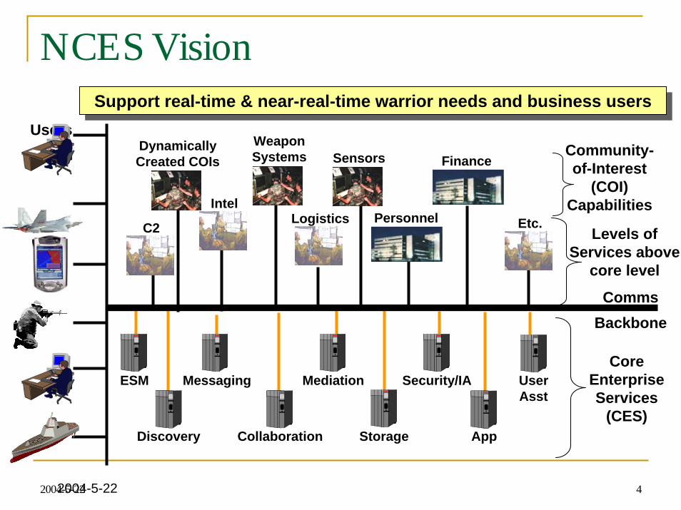
reconfiguration (SOADR) mechanisms for the DoD enterprise C2 system. DoD is moving into SOA as evidence by the recent development of NCES [12] and GES [5] (GIG Enterprise Services). For example, NCES has the following core services: storage, discovery, IA/security, messaging, collaboration, user assistant, and mediation. And on top of these core services, specialized services are available including C2, COI, Intel, Logistics, Weapon Systems, Sensors, Personnel, and Finance. The proposed architecture supplements the NCES system by providing survivability to the C2 system with dynamic configuration. Furthermore, the proposed architecture is easy to migrate and integrate with the application and services provided by the NCES because both of them have a common architecture framework, i.e., SOA.
The proposed SOADR is an extension of the existing Web Services (WS) architecture popularized by Microsoft’s .NET platform. The WS architecture has the following unique features:
• System interacts with each other with standard protocols such as SOAP, UDDI and WSDL;
• Each computation unit is a service and its specification is published in a WSDL file;
• Service lookup, searching, binding are done at runtime by the UDDI server; A significant advantage of this architecture is that new services can be added into the
system without changing the overall system architecture, and a client can communicate with any service using standard protocols. Recently, we have also developed techniques that allow services to be evaluated at runtime [18], and thus the WS architecture can be a good baseline for the DoD enterprise C2 system.
However, unlike the WS architecture, the DoD enterprise C2 system must also address real-time aspects, and it also must have a dynamic reconfiguration mechanism currently missing from the WS architecture. Specifically, the DoD enterprise C2 system must address reliability, safety, security and performance aspects that commercial WS
3
architecture does not address at this time. Furthermore, the DoD enterprise C2 system must also address the system as well as the network aspects in addition to just the application aspects as in the commercial WS architecture. These additional requirements make the proposed SOADR unique for DoD C2 applications. The proposed SOADR will automatically reconfigure participating services at runtime in real time in case of electronic attacks, service unavailability, network congestion, overload, security intrusion, and failures.
To facilitate dynamic reconfiguration, this paper uses the specifications in [14][15][18] to specify services in the framework. Specifically, this specification technique is an extension of WSDL, and it specifies a service by its ISC (Interfaces, Scenarios, Constraints) specifications. The Interface in the ISC represents the existing WSDL specifications and their extensions. The Scenarios in the ISC represent the operational scenarios of the service based on the ACDATE (Actors, Conditions, Data, Actions, Timing, and Events) model [15]. The ACDATE model is a semi-formal model and once a system is specified using ACDATE, it is possible to perform various automated analyses including simulation model checking [17] and Event Tree Analysis (ETA) [16]. The Constraints of the ISC specify system constraints such as timing constraints, reliability constraints and security constraints. The ISC specifications are used by the proposed dynamic reconfiguration tool to reconfigure WS in case of system failures or overload. An important benefit of using the ISC specification is that it allows dynamic verification at runtime in real time.
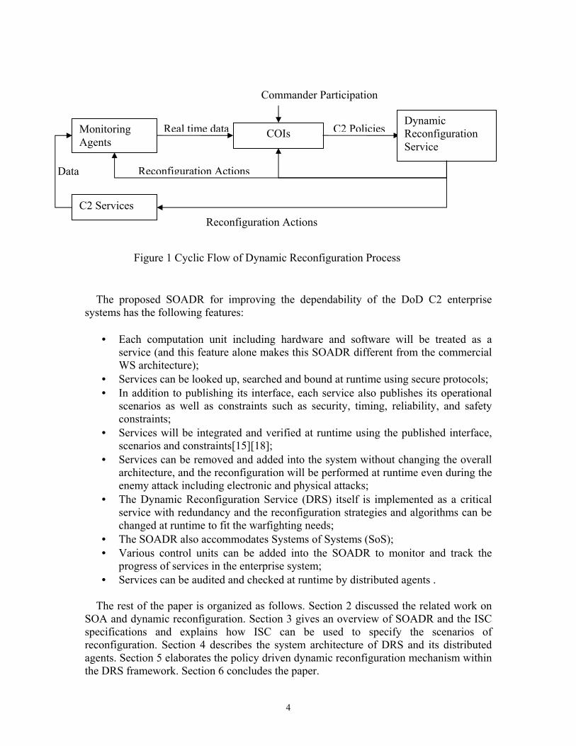
The dynamic reconfiguration mechanism is also controlled by a set of C2 policies, and these policies specify appropriate actions to take under various situations. These C2 policies can be pre-specified before system operations, but also they can be updated during runtime in real-time by the COI (community of interest) within the C2 system. For example, both NCES and GIG have real-time COIs that can be used to determine and construct C2 policies based on data collected from situation-aware monitoring agents or services. For this purpose, A Policy Specification Executable Language (PSEL) is designed to specify the reconfiguration policy that is dynamic changeable and executable at runtime. Thus, when the distributed situation-aware COI monitoring agent detects the changes in the operation environment, it informs the concerned COIs and then these COIs may update their C2 polices to adjust to the changing environment. This allows C2 policies to be updated in real time at runtime, and once the C2 policies are changed, the dynamic reconfiguration algorithm is changed as it is ruled by the C2 policies, even though the overall reconfiguration mechanism remains the same. In this way, commanders and decision makers make high-level decisions, based on the latest situation assessment, and let the C2 to actually implementation the transition plan. This cyclic reconfiguration framework is shown in Figure 1. Furthermore, it is important to note that multiple monitoring agents, COIs, and DRS can participate in this process, and this process is done in a distributed but collaborative manner.
4
The proposed SOADR for improving the dependability of the DoD C2 enterprise
systems has the following features:
• Each computation unit including hardware and software will be treated as a service (and this feature alone makes this SOADR different from the commercial WS architecture);
• Services can be looked up, searched and bound at runtime using secure protocols; • In addition to publishing its interface, each service also publishes its operational
scenarios as well as constraints such as security, timing, reliability, and safety constraints;
• Services will be integrated and verified at runtime using the published interface, scenarios and constraints[15][18];
• Services can be removed and added into the system without changing the overall architecture, and the reconfiguration will be performed at runtime even during the enemy attack including electronic and physical attacks;
• The Dynamic Reconfiguration Service (DRS) itself is implemented as a critical service with redundancy and the reconfiguration strategies and algorithms can be changed at runtime to fit the warfighting needs;
• The SOADR also accommodates Systems of Systems (SoS); • Various control units can be added into the SOADR to monitor and track the
progress of services in the enterprise system; • Services can be audited and checked at runtime by distributed agents .
The rest of the paper is organized as follows. Section 2 discussed the related work on
SOA and dynamic reconfiguration. Section 3 gives an overview of SOADR and the ISC specifications and explains how ISC can be used to specify the scenarios of reconfiguration. Section 4 describes the system architecture of DRS and its distributed agents. Section 5 elaborates the policy driven dynamic reconfiguration mechanism within the DRS framework. Section 6 concludes the paper.
Data Reconfiguration Actions
C2 PoliciesReal time dataMonitoring Agents
COIs Dynamic Reconfiguration Service
Figure 1 Cyclic Flow of Dynamic Reconfiguration Process
C2 Services
Commander Participation
Reconfiguration Actions
5
2. Related Work
Traditionally, many studies [1][2][9][11] have been focused on exploiting the software architecture specifications such as Architecture Description Language (ADL) to represent the configuration and connection of system components. ADL is an architecture language that formally specifies the structure of the components and their connections. Based on ADL, several dynamic architecture description languages have been developed with corresponding language tools such as Rapide [8]. While the former focuses more on the static perspective of system and system component architecture, the latter is ideally to express the dynamic transitional relationship among the working tasks.
Besides the approach based on the software architecture, there are other wide variety of
studies on runtime dynamic reconfiguration. These include the approaches exploiting the middle ware object oriented architecture such as CORBA, and augmenting of the operation systems and compilers technologies. In recent DARPA programs on survivable systems, several research activities are reported. Wells, et al., proposed a dynamic reconfiguration system based on an object services architecture in [19], where the reliable configuration model is built to connect the components, in addition, a utility model is used to optimize reconfiguration decisions given that the same function may be implemented by multiple services. Hiltunen, et al., proposed a dynamic reconfiguration framework in [6] where an event-driven middleware layer is used to reconfigure the system. In [8], Knight, Sullivan, Elder and Wang discussed several survivability issues and proposed a hierarchical survivable architecture.
Web services (WS) based systems [20] received significant attention recently as major
IT companies such as IBM and Microsoft are pushing for this new distributed computing paradigm. WS has significant advantages over traditional approaches because services are located, bound, and executed at runtime over the Internet using standard protocols such as UDDI, WSDL, and SOAP. Since it is relatively easy to perform system integration, applications developed in this paradigm can be viewed to form a loosely coupled architecture that provides maximum flexibility in terms of system structure and evolution. Furthermore, it makes the system more dependable because sub-systems can be removed from or added into the environment without changing the overall architecture [4]. This kind of architecture also maximizes system reusability because legacy systems can be wrapped and reused without significant changes.
On the other hand, although WS can be located, bound and executed at runtime and
over the Internet, once bound, the application will always call the same service unless another round of service relocating and rebinding are performed. Furthermore, there are times when deployed services need to be upgraded. Another weakness of the existing WS systems is that real-time and dependability requirements are not taken into consideration.
Our approach is based on the same spirit of utilizing a software architecture approach
to address the dynamic reconfiguration of the SOADR. We explored the feasibility of developing new service specification technique ISC which is an extension of WSDL to specify the static and dynamic structure of services. And based on the ISC, a runtime distributed dynamic reconfiguration tool has been designed and implemented.
6
The ISC specifications are used by the DRS to verify that any new services joining the
application satisfied the application’s requirements and constraints. In the proposed framework, services and applications are organized as services in a hierarchical directory tree. The DRS performs the service registration/de-registration, lookup, verification, binding, execution, monitoring at runtime, and the re-selection and re-binding in case of failures or overload.
3. Services-Oriented Architecture, ISC and PSEL
3.1 SOADR and ISC Service Specification Model The SOADR extends WS by requiring each service publishing its ISC specifications in
addition to its WSDL specifications. Like WS, the SOADR organizes each sub-system as a service, and each sub-system interoperates with each other via standard protocols. The differences between WS and SOADR are that the entire system, including all of its internally layers, is organized as a service architecture, rather than just at the application level like WS. In other words, the system will become inherently survivable in case of system failures because each layer of the system can be considered a loosely coupled architecture with services. Furthermore, each service will be specified using the ISC (Interfaces, Scenarios, and Constraints) convention defined as follows:
Interface Specification
• Input/Output parameters • Communication protocols • Interfaces with other sub-systems
Scenario Specification • Specify the service scenarios using the ACDATE model • Specify Interactions with Other Sub-systems
Constraint Specification • Based on the scenario model and ACDATE model • Specify the properties of the services must include, such as
– Reliability – Availability – Security – Timing – Concurrency – Performance – Sequence – Safety
• These constraints must be addressed at runtime to assure dependable computing. • Constraints are specified using a formal and executable policy specification
language PSEL.
7
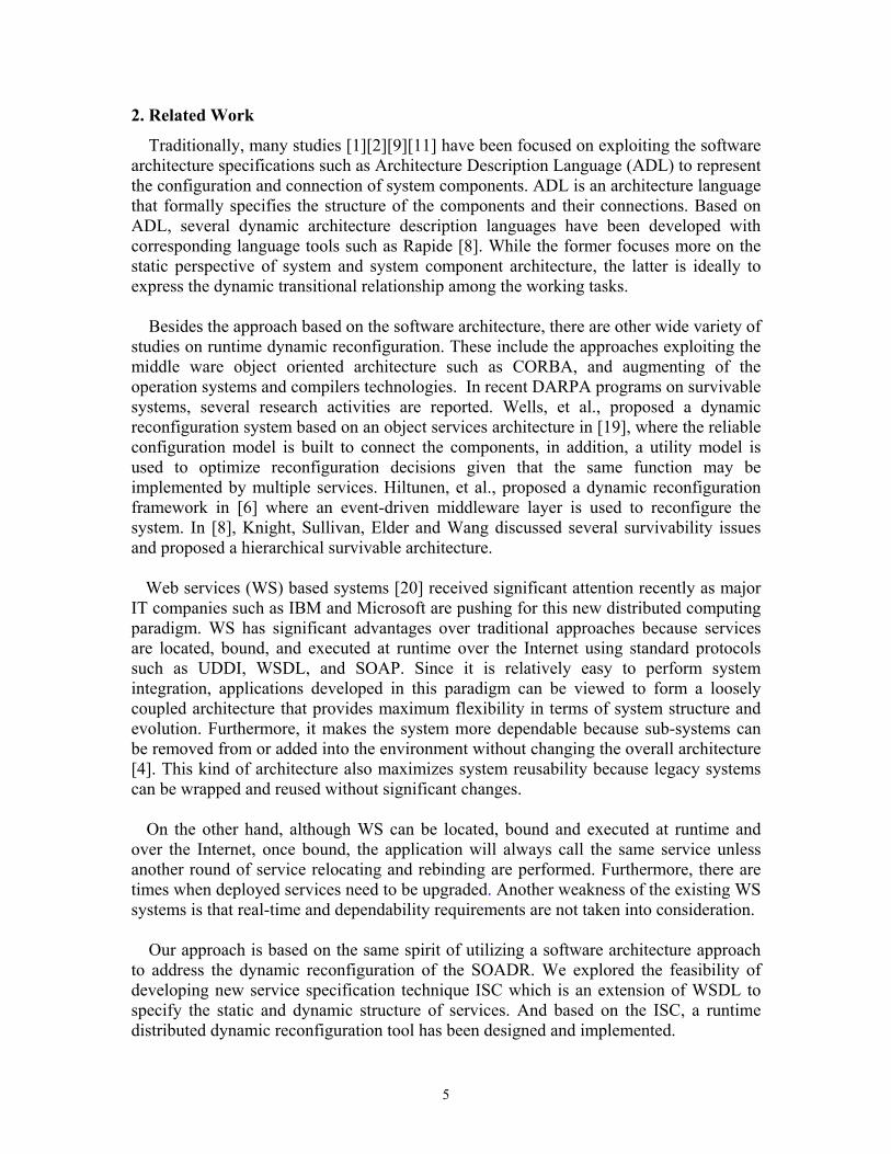
Note that a service can be formed by several other sub-services. In this case, the composite service has its own ISC specifications, and each of its sub-services also has its own individual ISC specifications, as shown in Figure 2.
Figure 2 A Composite Service Once the ISC specifications are available, it is possible to perform various static and
dynamic analyses such as completeness analysis, consistency analysis, state analysis, pattern analysis, usage analysis, security analysis, and safety analysis as discussed in [16], either at compile time or runtime.
For instance, a real-time message exchange service is a program that can forward
incoming messages from and to the registered parties. It also blocks any unauthorized messages that are trying to reach a registered party, and prevents a classified or sensitive message from being sent to any unauthorized party. The following shows some aspects of its ISC specifications:
Interface Specification: - Register/deregister: Participants register or deregister to the service with the
information of identification, address, authorization level etc, - Update registering information, - Messages receiving and forwarding.
Scenarios Specification: The scenarios can be used to describe a service functional behavior and non-functional constraints. One functional scenario for this service could be:
Begin: While (Event: Receiving) Action: Check the Authorization levels If (Condition: Authorized) Action: Forward Message
ELSE Action: Discard the Message End
Constraints Specification: - Timing constraints: Message forwarding should not take more than T seconds after
it receives the message at any time. This constraint is represented as: t(event. Forwarding) <= t (event. Receiving) + T. where t(event) is the event occurring time.
8
- Security Constraints: an unauthorized message cannot be sent to a registered party, and a classified message cannot be sent to an unauthorized party: L (Actor. Message) <= L (Actor. Receiver), where L(Actor) means the authorization levels of a specified Actor or Participants inside of the system.
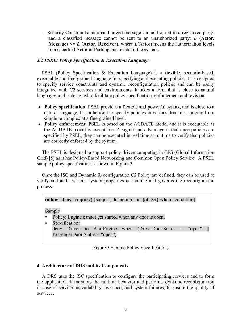
3.2 PSEL: Policy Specification & Execution Language
PSEL (Policy Specification & Execution Language) is a flexible, scenario-based, executable and fine-grained language for specifying and executing policies. It is designed to specify service constraints and dynamic reconfiguration polices and can be easily integrated with C2 services and environments. It takes a form that is close to natural languages and is designed to facilitate policy specification, enforcement and revision.
Policy specification: PSEL provides a flexible and powerful syntax, and is close to a
natural language. It can be used to specify policies in various domains, ranging from simple to complex at a fine-grained level.
Policy enforcement: PSEL is based on the ACDATE model and it is executable as the ACDATE model is executable. A significant advantage is that once policies are specified by PSEL, they can be executed in real time at runtime to verify that policies are correctly enforced by the system.
The PSEL is designed to support policy-driven computing in GIG (Global Information
Grid) [5] as it has Policy-Based Networking and Common Open Policy Service. A PSEL sample policy specification is shown in Figure 3.
Once the ISC and Dynamic Reconfiguration C2 Policy are defined, they can be used to
verify and audit various system properties at runtime and governs the reconfiguration process.
4. Architecture of DRS and its Components A DRS uses the ISC specification to configure the participating services and to form
the application. It monitors the runtime behavior and performs dynamic reconfiguration in case of service unavailability, overload, and system failures, to ensure the quality of services.
Figure 3 Sample Policy Specifications
(allow | deny | require) {subject} to{action} on {object} when {condition} Sample • Policy: Engine cannot get started when any door is open. • Specification:
deny Driver to StartEngine when (DriverDoor.Status = “open” || PassengerDoor.Status = “open”)
9
In the SOADR, every participating unit, including DRS, is a service and each service is
treated the same. As a service, the DRS provides the following functions: Dynamic service lookup, service publication, service binding, and service profiling, Registration and de-registration, Runtime services verification including constraint verification such as security
verification, interoperability checking, and performance monitoring, and Dynamic Service reconfiguration, which means by changing the ISC definition for a
service, it changes the behavior of a service runtime and even the DRS framework itself, since it is also a service of services.
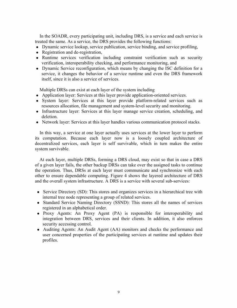
Multiple DRSs can exist at each layer of the system including
Application layer: Services at this layer provide application-oriented services. System layer: Services at this layer provide platform-related services such as
resources allocation, file management and system-level security and monitoring. Infrastructure layer: Services at this layer manage service creation, scheduling, and
deletion. Network layer: Services at this layer handles various communication protocol stacks. In this way, a service at one layer actually uses services at the lower layer to perform
its computation. Because each layer now is a loosely coupled architecture of decentralized services, each layer is self survivable, which in turn makes the entire system survivable.
At each layer, multiple DRSs, forming a DRS cloud, may exist so that in case a DRS
of a given layer fails, the other backup DRSs can take over the assigned tasks to continue the operation. Thus, DRSs at each layer must communicate and synchronize with each other to ensure dependable computing. Figure 4 shows the layered architecture of DRS and the overall system infrastructure. A DRS is a service with several sub-services:
Service Directory (SD): This stores and organizes services in a hierarchical tree with
internal tree node representing a group of related services. Standard Service Naming Directory (SSND): This stores all the names of services
registered in an alphabetical order. Proxy Agents: An Proxy Agent (PA) is responsible for interoperability and
integration between DRS, services and their clients. In addition, it also enforces security accessing control.
Auditing Agents: An Audit Agent (AA) monitors and checks the performance and user concerned properties of the participating services at runtime and updates their profiles.
10
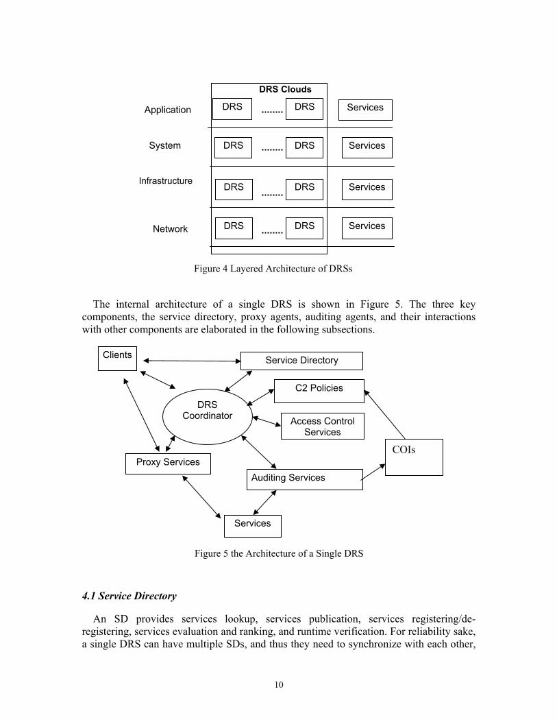
The internal architecture of a single DRS is shown in Figure 5. The three key
components, the service directory, proxy agents, auditing agents, and their interactions with other components are elaborated in the following subsections.
4.1 Service Directory
An SD provides services lookup, services publication, services registering/de-registering, services evaluation and ranking, and runtime verification. For reliability sake, a single DRS can have multiple SDs, and thus they need to synchronize with each other,
Service Directory
Auditing Services Proxy Services
Access Control Services
C2 Policies
Clients
Services
DRS Coordinator
COIs
DRS DRS Services
DRS DRS Services
DRS DRS Services
DRS DRS ServicesNetwork
DRS Clouds
Figure 4 Layered Architecture of DRSs
Application
System
Infrastructure
Figure 5 the Architecture of a Single DRS
11
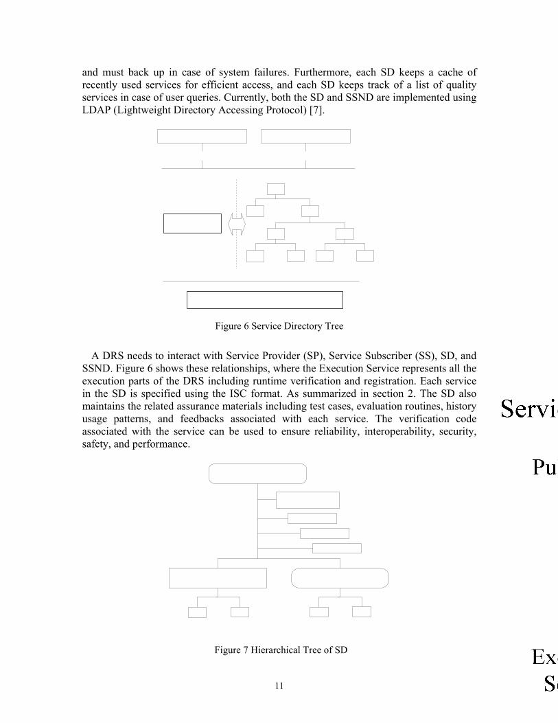
and must back up in case of system failures. Furthermore, each SD keeps a cache of recently used services for efficient access, and each SD keeps track of a list of quality services in case of user queries. Currently, both the SD and SSND are implemented using LDAP (Lightweight Directory Accessing Protocol) [7].
A DRS needs to interact with Service Provider (SP), Service Subscriber (SS), SD, and SSND. Figure 6 shows these relationships, where the Execution Service represents all the execution parts of the DRS including runtime verification and registration. Each service in the SD is specified using the ISC format. As summarized in section 2. The SD also maintains the related assurance materials including test cases, evaluation routines, history usage patterns, and feedbacks associated with each service. The verification code associated with the service can be used to ensure reliability, interoperability, security, safety, and performance.
Figure 6 Service Directory Tree
Figure 7 Hierarchical Tree of SD
12
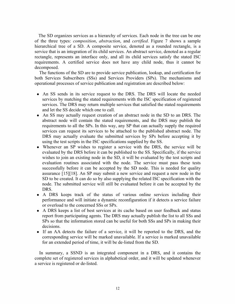
The SD organizes services as a hierarchy of services. Each node in the tree can be one
of the three types: composition, abstraction, and certified. Figure 7 shows a sample hierarchical tree of a SD. A composite service, denoted as a rounded rectangle, is a service that is an integration of its child services. An abstract service, denoted as a regular rectangle, represents an interface only, and all its child services satisfy the stated ISC requirements. A certified service does not have any child node, thus it cannot be decomposed.
The functions of the SD are to provide service publication, lookup, and certification for both Services Subscribers (SSs) and Services Providers (SPs). The mechanisms and operational processes of service publication and registration are described below:
An SS sends in its service request to the DRS. The DRS will locate the needed
services by matching the stated requirements with the ISC specification of registered services. The DRS may return multiple services that satisfied the stated requirements and let the SS decide which one to call.
An SS may actually request creation of an abstract node in the SD to an DRS. The abstract node will contain the stated requirements, and the DRS may publish the requirements to all the SPs. In this way, any SP that can actually supply the required services can request its services to be attached to the published abstract node. The DRS may actually evaluate the submitted services by SPs before accepting it by using the test scripts in the ISC specifications supplied by the SS.
Whenever an SP wishes to register a service with the DRS, the service will be evaluated by the DRS before it can be published to the SS. Specifically, if the service wishes to join an existing node in the SD, it will be evaluated by the test scripts and evaluation routines associated with the node. The service must pass these tests successfully before it can be accepted by the SD node. This is needed for quality assurance [15][18]. An SP may submit a new service and request a new node in the SD to be created. It can do so by also supplying the related ISC specification with the node. The submitted service will still be evaluated before it can be accepted by the DRS.
A DRS keeps track of the status of various online services including their performance and will initiate a dynamic reconfiguration if it detects a service failure or overload to the concerned SSs or SPs.
A DRS keeps a list of best services at its cache based on user feedback and status report from participating agents. The DRS may actually publish the list to all SSs and SPs so that the information stored can be useful for both SSs and SPs in making their decisions.
If an AA detects the failure of a service, it will be reported to the DRS, and the corresponding service will be marked unavailable. If a service is marked unavailable for an extended period of time, it will be de-listed from the SD.
In summary, a SSND is an integrated component in a DRS, and it contains the
complete set of registered services in alphabetical order, and it will be updated whenever a service is registered or de-listed.

13
4.2 Proxy Agents
A PA coordinates between services and their clients at runtime. Due to its role as a broker, it is also a place where access control can be enforced. A PA is created whenever an abstract node in the SD is created. It will be activated whenever one of the services under the abstract node is called. A PA may consist of one or multiple Service Proxies, Access Control Lists, and Proxy Scenario Lists. Because all the services under the abstract node provide the same functionality, each can replace each other whenever there is a need of reconfiguration. The functions of a PA are briefly described as follows.
The interface of PA is defined by the corresponding abstract node in the SD. In each
abstract node there is one corresponding PA. When a client initiates a service request, the DRS will return the address of
corresponding PA to the client instead of the address of a service directly. In other words, the client interacts with the PA only.
Each registered service must interoperate with its corresponding PA. PA responses to any service invocation by invoking the corresponding service proxy
scenario and checks with the accessing control list in the mean time. A proxy scenario is a scenario given by service providers that instruct the PA how to map the standard interface to its proprietary counterparts. Once defined, it provides a universal form for service accessing. By redefining the proxy scenario for a service, it changes the way service will be accessed automatically as long as it confirms with the abstract service definition.
Now consider an example of the proxy scenario. Assume we have several Echo Web
Services which always echo back whatever input it gets over the network. However, they
Figure 8 Interaction of Service Invocation via Proxy Agent
14
have different interface definition. They are “1)String echo(string input)”, “2)String echome(string input)”, “3)String echoback(string input)”, respectively. So, the DRS will define an abstract service dedicated for this type of service “Echo” and have an standard interface definition as “string echo(string input)” which is the only interface for the client application. The proxy scenario for each of the services can be defined as:
ProxyScenario_EchoService1_echo Action: echo ProxyScenario_EchoService2_echo Action: echome ProxyScenario_EchoService3_echo Action: echoback
The PAs in the DRS framework provide flexibility, interoperability, service integration, and service reconfigurations. Figure 8 shows the interaction of service invocation via proxy agents.
4.3 Auditing Agents
An AA monitors the status of the participating services at runtime. Each participating service will have at least one AA, but an AA may audit multiple services. An AA has the following behaviors:
An AA is created whenever there is at least one service is bounded to a client
through a PA; An AA monitors the status and performances of services, and notifies the DRS in
case of failures or overload. An AA is also responsible for creating and maintaining a profile for each active
service to keep track of its performance and usage patterns. Standard auditing scenarios are defined for each type of services and SPs can provide
additional auditing scenarios and data for better decision making. Two common auditing scenarios are: - Hello Auditing Scenario: this detects the liveliness of the concerned service
periodically - Threshold Auditing Scenario: this is used for performance or other constraints-
related audits. When the reported data are outside the normal range, the AA will report immediately to the DRS to initiate a reconfiguration. For example, an AA for a video multicast service will inform the DRS if the packets/frames lost rate exceeds a certain limit.
5. Reconfiguration
A DRS removes a service from active duty when it detects that the service is not responsive. The DRS then assign the related tasks to another service to continue the operation at runtime. It makes the reconfiguration decision based on the current C2 policies. The C2 policies may be pre-determined or determined at runtime by the COIs. This process is illustrated as follows. The monitoring agents collect data of the
15
participating services, and send the data to the concerned COIs. Each COI may have its reasoning algorithms and have concerned commanders to participate in the decision making. Based on the situation assessment, commanders may update the current C2 in a collaborative manner, and send the updated C2 policies to the DRS. The DRS will then perform reconfiguration according to the updated C2 policies.
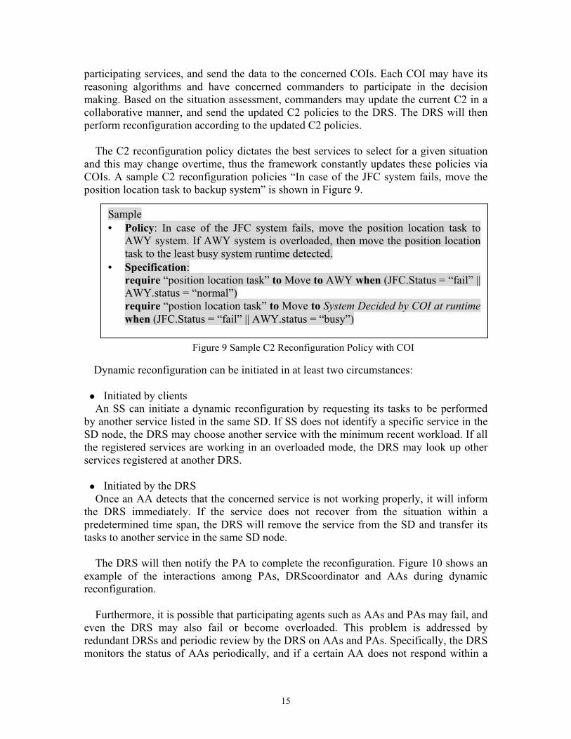
The C2 reconfiguration policy dictates the best services to select for a given situation
and this may change overtime, thus the framework constantly updates these policies via COIs. A sample C2 reconfiguration policies “In case of the JFC system fails, move the position location task to backup system” is shown in Figure 9.
Dynamic reconfiguration can be initiated in at least two circumstances: Initiated by clients An SS can initiate a dynamic reconfiguration by requesting its tasks to be performed
by another service listed in the same SD. If SS does not identify a specific service in the SD node, the DRS may choose another service with the minimum recent workload. If all the registered services are working in an overloaded mode, the DRS may look up other services registered at another DRS.
Initiated by the DRS Once an AA detects that the concerned service is not working properly, it will inform
the DRS immediately. If the service does not recover from the situation within a predetermined time span, the DRS will remove the service from the SD and transfer its tasks to another service in the same SD node.
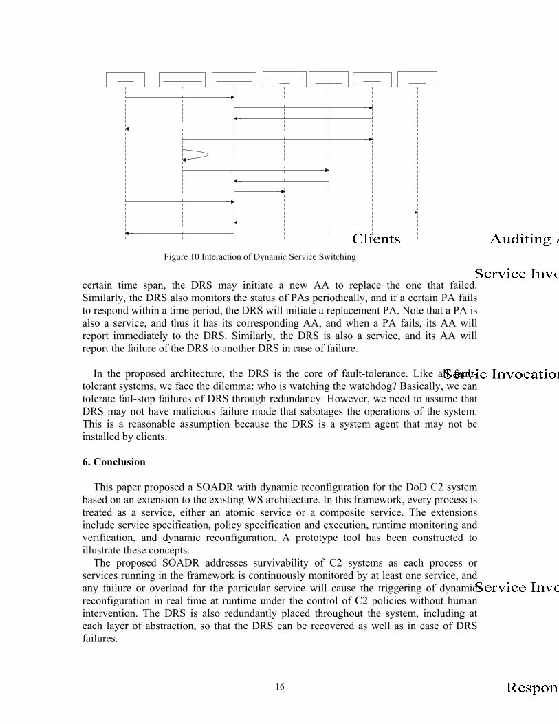
The DRS will then notify the PA to complete the reconfiguration. Figure 10 shows an
example of the interactions among PAs, DRScoordinator and AAs during dynamic reconfiguration.
Furthermore, it is possible that participating agents such as AAs and PAs may fail, and
even the DRS may also fail or become overloaded. This problem is addressed by redundant DRSs and periodic review by the DRS on AAs and PAs. Specifically, the DRS monitors the status of AAs periodically, and if a certain AA does not respond within a
Figure 9 Sample C2 Reconfiguration Policy with COI
Sample • Policy: In case of the JFC system fails, move the position location task to
AWY system. If AWY system is overloaded, then move the position location task to the least busy system runtime detected.
• Specification: require “position location task” to Move to AWY when (JFC.Status = “fail” || AWY.status = “normal”) require “postion location task” to Move to System Decided by COI at runtime when (JFC.Status = “fail” || AWY.status = “busy”)
16
certain time span, the DRS may initiate a new AA to replace the one that failed. Similarly, the DRS also monitors the status of PAs periodically, and if a certain PA fails to respond within a time period, the DRS will initiate a replacement PA. Note that a PA is also a service, and thus it has its corresponding AA, and when a PA fails, its AA will report immediately to the DRS. Similarly, the DRS is also a service, and its AA will report the failure of the DRS to another DRS in case of failure.
In the proposed architecture, the DRS is the core of fault-tolerance. Like all fault-
tolerant systems, we face the dilemma: who is watching the watchdog? Basically, we can tolerate fail-stop failures of DRS through redundancy. However, we need to assume that DRS may not have malicious failure mode that sabotages the operations of the system. This is a reasonable assumption because the DRS is a system agent that may not be installed by clients.
6. Conclusion
This paper proposed a SOADR with dynamic reconfiguration for the DoD C2 system based on an extension to the existing WS architecture. In this framework, every process is treated as a service, either an atomic service or a composite service. The extensions include service specification, policy specification and execution, runtime monitoring and verification, and dynamic reconfiguration. A prototype tool has been constructed to illustrate these concepts.
The proposed SOADR addresses survivability of C2 systems as each process or services running in the framework is continuously monitored by at least one service, and any failure or overload for the particular service will cause the triggering of dynamic reconfiguration in real time at runtime under the control of C2 policies without human intervention. The DRS is also redundantly placed throughout the system, including at each layer of abstraction, so that the DRS can be recovered as well as in case of DRS failures.
Figure 10 Interaction of Dynamic Service Switching
17
The proposed SOADR also addresses rapid development and evaluation. As any new software can be developed as a service, and once it is placed in the SOADR, it can be picked up by other applications running on top of SOADR. The proposed SOADR like existing SOA such as .NET allow multiple programs to interoperate using standard Internet protocols such as UDDI.
Acknowledgements We would like to thank Yinong Chen for his contribution in reviewing this paper. References [1] R. Allen and D. Garlan. “Formalizing Architectural Connection”, Proc. of IEEE
International Conference on Software Engineering, 1994, pp. 71-80. [2] M. Aksit and Z. Choukair, “Dynamic, Adaptive and Reconfigurable Systems
Overview and Prospective Vision”, Proc. of IEEE International Conference on Distributed Computing Systems Workshops, 2003, pp. 84 -89.
[3] X. Bai, W. T. Tsai, R. Paul, K. Feng, and L. Yu, “Scenario-based Modeling and Its Applications to Object-Oriented Analysis, Design, and Testing”, Proc. of IEEE WORDS, 2002, pp. 140-151.
[4] D. Cotroneo, C. Di Flora, S. Russo, “Improving Dependability of Service Oriented Architectures for Pervasive Computing”, Proc. of WORDS, 2003, pp. 74-81.
[5] Global Information Grid (GIG) Enterprise Services (ES), http://ges.dod.mil/. [6] M. A. Hiltunen, R. D. Schlichting, C. A. Ugarte, and G. T. Wong. “Survivability
through Customization and Adaptability: The Cactus Approach”, DARPA Information Survivability Conference and Exposition (DISCEX 2000), 2000, pp. 294-307.
[7] T. Howes and M. Smith, LDAP: Programming Directory-Enabled Applications with Lightweight Directory Access Protocol, Macmillan Technical Publishing, 1997.
[8] J. C. Knight, K. J. Sullivan, M. C. Elder, and C. Wang, “Survivability Architectures: Issues and Approaches”, DARPA Information Survivability Conference and Exposition-Volume 2 (DISCEX 2000), 2000, pp. 1157-1171.
[9] D. C. Luckham, “Specification and Analysis of System Architecture Using Rapide”, IEEE Transactions on Software Engineering 21 (4), 1995, pp. 336-355.
[10] P. Periorellis, J, Dobson, The Travel Agent Case Study, DSoS Project, IST-1999-11585, 2001.
[11] J. M. Purtilo, “The Polylith Software Bus”, ACM TOPLAS (16) 1, 1994, pp.151-174.
[12] Net Centric Enterprise Services (NCES), http://www.disa.mil/ca/buyguide/feature/nces.html
[13] A. Troelsen, C# and the .NET Platform, Addison Wesley, Reading, MA, 2001. [14] W. T. Tsai, R. Paul, Y. Wang, C. Fan, and D. Wang, “Extending WSDL to Facilitate
Web Services Testing”, Proc. of IEEE HASE, 2002, pp. 171-172. [15] W. T. Tsai, R. Paul, Z. Cao, L. Yu, A. Saimi, and B. Xiao, “Verification of Web
Services Using an Enhanced UDDI Server”, Proc. of IEEE WORDS, 2003, pp. 131-138.
[16] W. T. Tsai, C. Fan, R. Paul, and L. Yu, “Automated Event Tree Analysis from
18
Scenario Specifications”, Proc. of IEEE ISSRE, 2003, pp.240-241. [17] W. T. Tsai, L. Yu, R. Paul, C. Fan, and X. Liu, “Rapid Scenario-Based Simulation
and Model Checking for Embedded System”, Proc. of International Conference on SEA, 2003, pp 568-573.
[18] W. T. Tsai, R. Paul, and L. Yu, A. Saimi, and Z. Cao, “Scenario-Based Web Service Testing with Distributed Agents”, IEICE Transaction on Information and System, 2003, v.E86-D, no. 10, pp.2130-2144.
[19] D. Wells, S. Ford, D. Langworthy, and N. Wells. “Software Survivability”, DARPA Information Survivability Conference and Exposition-Volume 2 (DISCEX 2000), 2000, pp. 1241-1255.
[20] W3C, Web Services Architecture Working Group. http://www.w3.org/2002/ws/arch/.
2004-5-22 1
Service-Oriented Architecture for Command and Control Systems with Dynamic Reconfiguration
Raymond A. PaulDepartment of DefenseWashington, [email protected]
2004-5-22 2
Outlines
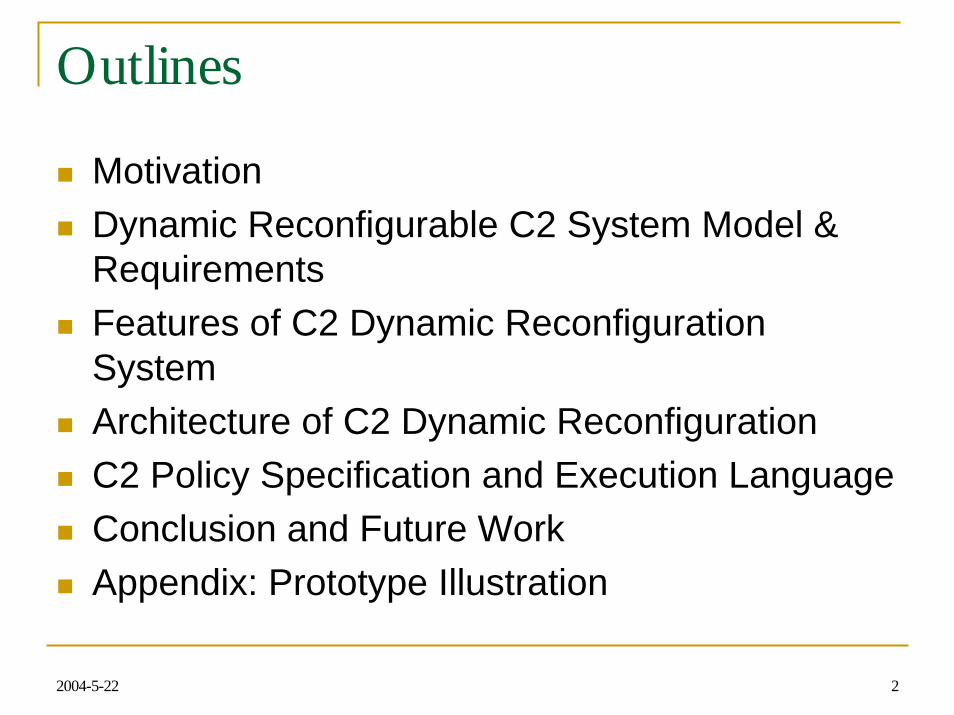
MotivationDynamic Reconfigurable C2 System Model & RequirementsFeatures of C2 Dynamic Reconfiguration SystemArchitecture of C2 Dynamic ReconfigurationC2 Policy Specification and Execution LanguageConclusion and Future WorkAppendix: Prototype Illustration
2004-5-22 3
Motivation
Command and Control (C2) systems are moving into SOA as evidenced by the recent development of NCES and GES (GIG Enterprise Services).C2 system may need to be compatible with NCES and GES. Modern warfighting needs a dynamic, adaptable and agile force supported by rapidly changing technology.
2004-5-22 4
NCES Vision
CoreEnterpriseServices
(CES)
CommsBackbone
Community-of-Interest
(COI) Capabilities
Users
MessagingESM
Discovery Collaboration
Mediation Security/IA
AppStorage
UserAsst
Levels of Services above
core level
Support real-time & near-real-time warrior needs and business usersSupport real-time & near-real-time warrior needs and business users
C2
Intel
Weapon Systems
Dynamically Created COIs
Logistics
Sensors
Personnel
Finance
Etc.
2004-5-22
2004-5-22 5
Service-Oriented Architecture (SOA)
System interacts with each other with standard protocols such as SOAP, UDDI and WSDL;Each computation unit is a service and its specification is published in a WSDL file;Service lookup, searching, binding are done at runtime by the UDDI server;New services can be added into the system without changing the overall system architectureThe enterprise C2 system can easily interoperate with numerous existing systems including weapon systems, communications, sensor systems, and other C2 systems for commanders.
2004-5-22 6
Limitation of Current SOA for C2However, current SOA cannot satisfy the survivability requirements for mission-critical C2 systems. It fails to discover and rebind to available services automatically upon system failures or overload.C2 systems will be subjected to various attacks including physical attacks as well as electronic attacks.One key feature of survivability is that the C2 system must be able to dynamically reconfigure its participating subsystems and continue its intended operations in case of failures or overload.

2004-5-22 7
Dynamic Reconfiguration Model for SOA
System I
Reconfiguration MgrReconfiguration MgrC2 SystemConfig. I.
System II
ReconfigurationConstraints Checker
ReconfigurationConstraints Checker
C2 SystemConfig. II.
ReconfigurationPolicy
Valid Policy
ReconfigurationAgents
ReconfigurationAgents
Actions
2004-5-22 8
Requirements for the distributed dynamic reconfiguration.
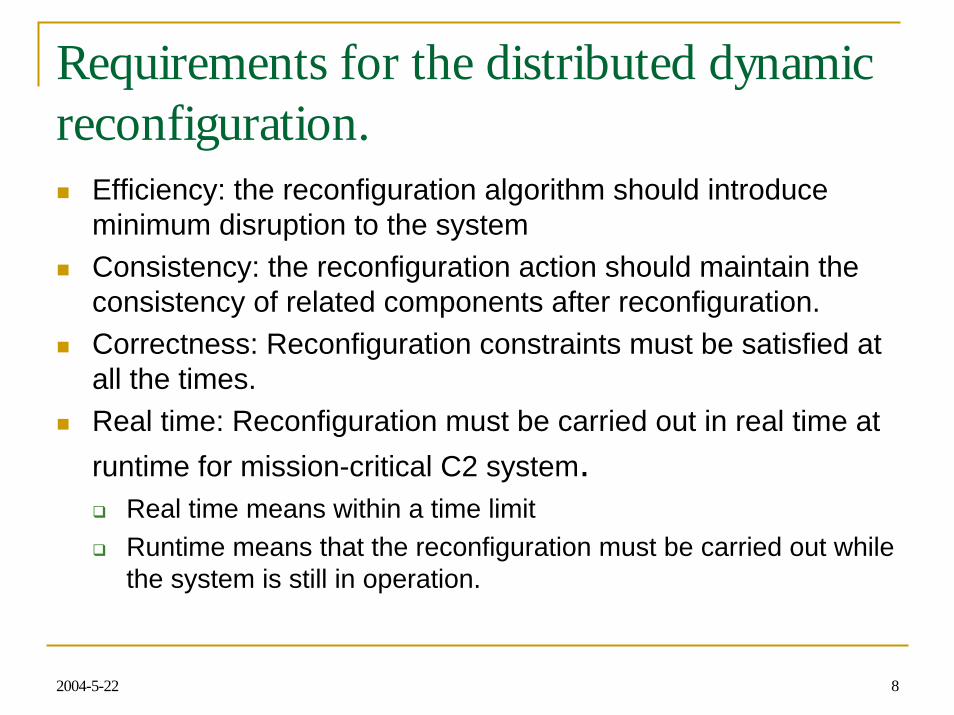
Efficiency: the reconfiguration algorithm should introduce minimum disruption to the systemConsistency: the reconfiguration action should maintain the consistency of related components after reconfiguration.Correctness: Reconfiguration constraints must be satisfied at all the times.Real time: Reconfiguration must be carried out in real time at runtime for mission-critical C2 system.
Real time means within a time limitRuntime means that the reconfiguration must be carried out whilethe system is still in operation.
2004-5-22 9
Requirements for the distributed dynamic reconfiguration (cont’)
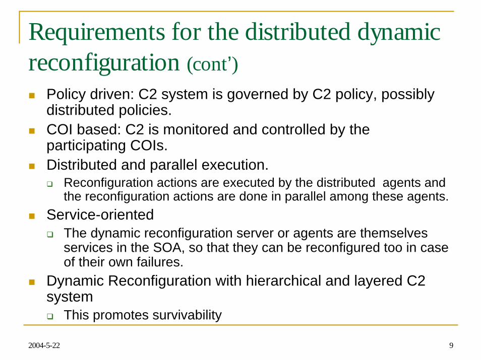
Policy driven: C2 system is governed by C2 policy, possibly distributed policies.COI based: C2 is monitored and controlled by the participating COIs. Distributed and parallel execution.
Reconfiguration actions are executed by the distributed agents and the reconfiguration actions are done in parallel among these agents.
Service-orientedThe dynamic reconfiguration server or agents are themselves services in the SOA, so that they can be reconfigured too in case of their own failures.
Dynamic Reconfiguration with hierarchical and layered C2 system
This promotes survivability
2004-5-22 10
Layered Dynamic Reconfiguration Architecture
DRS DRS Services
DRS DRS Services
DRS DRS Services
DRS DRS ServicesNetwork
DRS Clouds
Application
System
Infrastructure
2004-5-22 11
Layered Dynamic Reconfiguration Architecture (cont’)
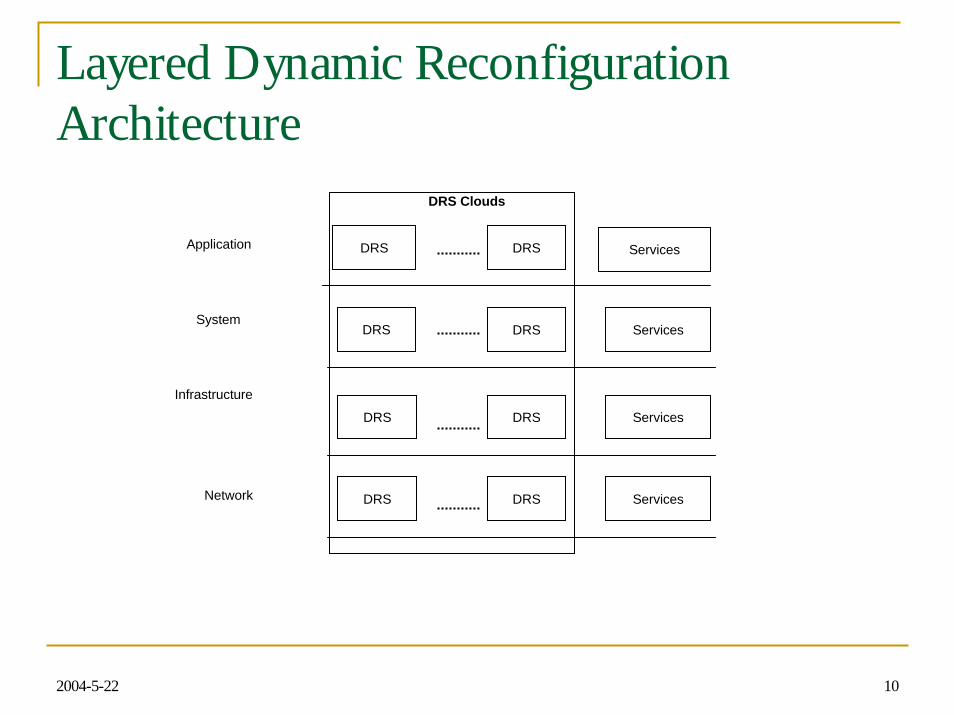
Dynamic Reconfigurability is embedded in each layer of the entire system, and at each level multiple DRS synchronized with each other to avoid any single point of failure.
2004-5-22 12
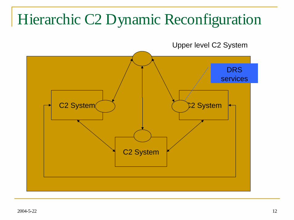
Hierarchic C2 Dynamic Reconfiguration Upper level C2 System
C2 System
C2 System
C2 System
DRS services
2004-5-22 13
Hierarchic C2 Dynamic Reconfiguration
SOADR (SOA with Dynamic Reconfiguration) allows the distributed system to be constructed in a hierarchical manner. A composite system can be constructed from primitive systems with dynamic reconfigurability and these in turns can be constructed into more complex composite system with dynamic reconfigurability.
2004-5-22 14
SOA with Dynamic Reconfiguration
Every participating C2 unit, including DRS, is a service and each service is treated the same. As a service, the DRS provides the following functions:
Dynamic service lookup, service publication, service binding, and service profiling,Registration and de-registration,Runtime services verification including constraint verification such as security verification, interoperability checking, and performance monitoring.
2004-5-22 15
SOA with Dynamic Reconfiguration (cont’)
The Dynamic Reconfiguration Service (DRS) is implemented as a critical service with redundancy and the reconfiguration strategies and algorithms can be changed at runtime to fit the warfighting needs.With this kind of mechanism, the behavior of the SOA can be changed in real time at runtime, and even the behavior of DRS can be changed too.
2004-5-22 16
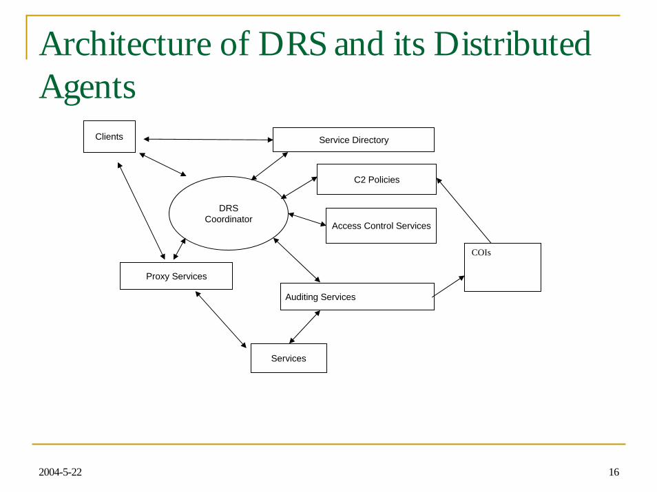
Architecture of DRS and its Distributed Agents
Service Directory
Auditing Services
Proxy Services
Access Control Services
C2 Policies
Clients
Services
DRSCoordinator
COIs
2004-5-22 17
Architecture of DRS (cont’) Major Agents
Service Directory (SD): This stores and organizes services in a hierarchical tree with internal tree node representing a group of related services. Proxy Agents: An Proxy Agent (PA) is responsible for interoperability and integration between DRS, services and their clients. In addition, it also enforces security accessing control. Auditing Agents: An Audit Agent (AA) monitors and checks the performance and user concerned properties of the participating services at runtime and updates their profiles.
2004-5-22 18
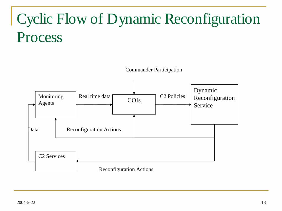
Cyclic Flow of Dynamic ReconfigurationProcess
Data Reconfiguration Actions
C2 PoliciesReal time dataMonitoring Agents COIs
Dynamic Reconfiguration Service
C2 Services
Commander Participation
Reconfiguration Actions
2004-5-22 19
Dynamic Policy Adaptation and Validation
Dynamic Policy AdaptationThrough the cyclic flow of situation aware of environment data collect and monitoring, reconfiguration policy formation, policy validation and reconfiguration execution.Commander in the loop
Policy Validation Reconfiguration Constraints are represented by Meta C2 Policy and it will validate the reconfiguration policy in real time at runtime

2004-5-22 20
GIG Enterprise ServicesGIG Enterprise ServicesSOADR Supports real-time & near-real-time warrior needsSOADR Supports real-time & near-real-time warrior needs
DoD (Title 10) IC (Title 50)
UsersUsers
Business Domains Warfighter Domains
Domain/ COI
Capabilities
ICOrg Spaces
National Intelligence Domain
Transformational Communications (TC) & Computing Infrastructure
ICSIS Community Space
Technical Infrastructure
Domain
Levels of Services
Above Core Level
COI’s
Capability Integrator
Inst
alla
tions
&
Env
iron
men
t
Hum
an R
esou
rces
M
anag
emen
t
Acq
uisi
tion
Stra
tegi
c Pl
anni
ng&
Bud
get
Log
istic
s
Acc
ount
ing
& F
inan
ce
Governance
COI’s
Capability Integrator
Com
man
d &
C
ontr
ol
Bat
tlesp
ace
Aw
aren
ess
Forc
e A
pplic
atio
n
Prec
isio
n L
ogis
tics
Prot
ectio
n
Governance
Net-Centric Enterprise Services (NCES)
ApplicationUser
AssistantStorage Messaging IA/Security
IA/SecurityESM
IA/SecurityESM
IA/SecurityESM
Discovery
IA/SecurityESM
Collaboration
IA/SecurityESM
Enterprise Service
Management (ESM)
Mediation
IA/SecurityESM
IA/SecurityESM
ESM
IA/Security
2004-5-22 21
Cyclic Flow of Dynamic ReconfigurationProcess (cont’)
The dynamic reconfiguration mechanism is controlled by a set of C2 policies, and these policies specify appropriate actions to take under various situations.These C2 policies can be pre-specified before system operations, but also they can be updated during runtime in real-time by the COI (community of interest) within the C2 system.
For example, both NCES and GIG have real-time COIs that can be used to determine and construct C2 policies based on data collected from situation-aware monitoring agents or services.
The distributed situation-aware COI monitoring agent detects the changes in the operation environment, it informs the concerned COIs and then these COIs may update their C2 polices to adjust to the changing environment.
2004-5-22 22
Cyclic Flow of Dynamic ReconfigurationProcess (cont’)
Once the C2 policies are changed, the dynamic reconfiguration is changed as it is ruled by the C2 policies, even though the overall reconfiguration mechanism remains the same. In this way, commanders and decision makers make high-level decisions, based on the latest situation assessment, and let the SOA to actually implementation the transition plan.Multiple monitoring agents, COIs, and DRS can participate in this process, and this process is done in a distributed but collaborative manner.
2004-5-22 23
Policy Specification & ExecutionLanguage (PSEL) PSEL is designed to
Support policy-driven computing in GIG as it has Policy-Based Networking and Common Open Policy Service. Specify service constraints and dynamic reconfiguration polices and can be easily integrated with C2 services and environments.Be well formed thus facilitate policy specification, enforcement and revision.

2004-5-22 24
Policy Enforcement by Trusted Agents
Once the dynamic reconfiguration C2 Policy are defined, they can be used to verify and audit various system properties at runtime and governs the reconfiguration process.It is enforced by distributed trust agents.
2004-5-22 25
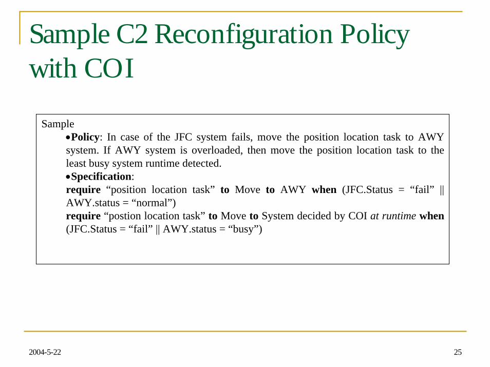
Sample C2 Reconfiguration Policywith COI
Sample•Policy: In case of the JFC system fails, move the position location task to AWY system. If AWY system is overloaded, then move the position location task to the least busy system runtime detected.•Specification:require “position location task” to Move to AWY when (JFC.Status = “fail” || AWY.status = “normal”)require “postion location task” to Move to System decided by COI at runtime when(JFC.Status = “fail” || AWY.status = “busy”)
2004-5-22 26
Conclusion
This paper proposed a SOA with dynamic reconfiguration for the DoD C2 system based on an extension to the existing WS architecture. In this framework, every process is treated as a service, either an atomic service or a composite service. The extensions include service specification, policy specification and execution, runtime monitoring and verification, and dynamic reconfiguration. A prototype tool has been implemented to illustrate these concepts.
2004-5-22 27
Conclusion
The proposed SOADR addresses survivability of C2 systems as each process or services running in the framework is continuously monitored by at least one service, and any failure or overload for the particular service will trigger dynamic reconfiguration in real time at runtime under the control of C2 policies without human intervention. The proposed SOADR also addresses rapid development and evaluation. As any new software can be developed as a service, and once it is placed in the SOADR, it can be picked up by other applications running on top of SOADR.
2004-5-22 28
Future Work
Model-driven dynamic reconfigurationEmbedded C2 system, NECS and GES with Dynamic Reconfigurability
Once the NECS or GES system is specified, the deployed system automatically has the capability of dynamic reconfiguration.
Policy-driven environment detection and monitoring frameworkReconfiguration execution framework
2004-5-22 29
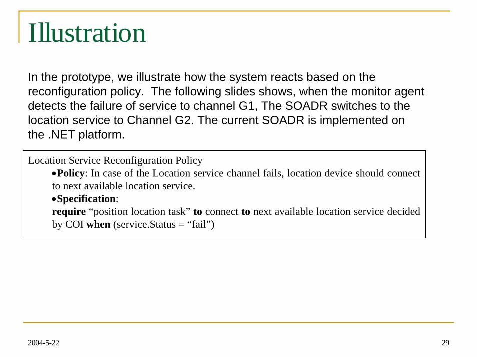
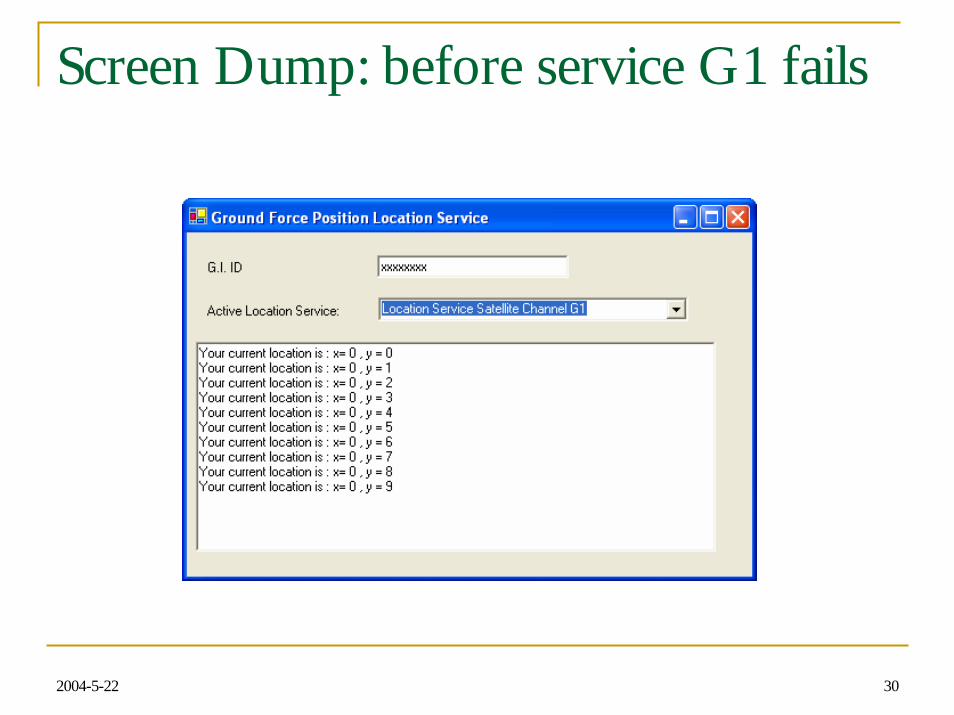
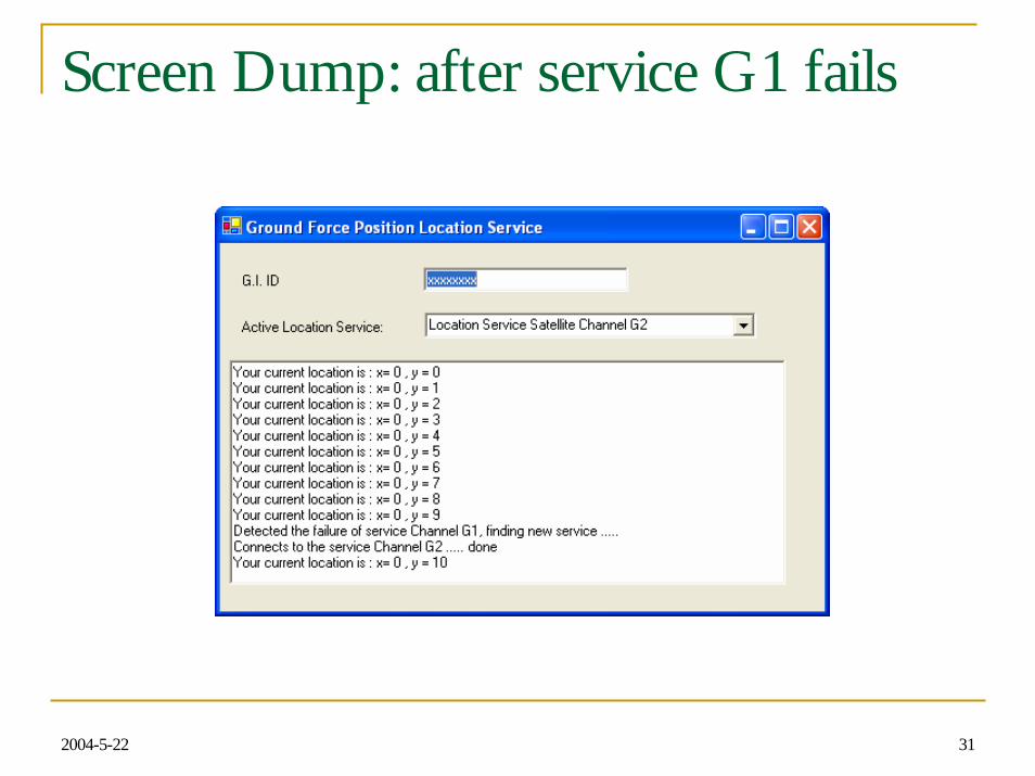
IllustrationIn the prototype, we illustrate how the system reacts based on the reconfiguration policy. The following slides shows, when the monitor agent detects the failure of service to channel G1, The SOADR switches to the location service to Channel G2. The current SOADR is implemented on the .NET platform.
Location Service Reconfiguration Policy•Policy: In case of the Location service channel fails, location device should connect to next available location service.•Specification:require “position location task” to connect to next available location service decided by COI when (service.Status = “fail”)
2004-5-22 30
Screen Dump: before service G1 fails
2004-5-22 31
Screen Dump: after service G1 fails