service station manual - cadre cycle 1100.pdf · service station manual griso 1100 while the basic...
TRANSCRIPT

SERVICE STATION MANUAL854331
GRISO 1100

SERVICE STATIONMANUAL
GRISO 1100
While the basic features as described and illustrated in this manual remain unchanged, Moto Guzzis.p.a. reserves the right to introduce changes to their own models at any time. All rights regardingelectronic data storage, total or partial reproduction or adaptation of this manual by any means are
reserved for all Countries. Third party products or services referred to in this manual should be consideredonly informative and are not binding. Moto Guzzi s.p.a. shall not be liable for any functions or use of these
products.
SERVICE STATION MANUALGRISO 1100
This manual provides the main information to carry out regular maintenance operations on your vehicle.This manual is intended to Moto Guzzi Dealers and their qualified mechanics; several concepts havebeen deliberately omitted as they are considered unnecessary. As it is not possible to include completemechanical notions in this manual, users should have basic mechanical knowledge or minimumknowledge about the procedures involved when repairing scooters. Without this knowledge, repairing orchecking the vehicle may be inefficient or even dangerous. As the vehicle repair and check proceduresare not described in detail, be extremely cautious so as not to damage components or injure individuals.In order to optimise customer satisfaction when using our vehicles, Moto Guzzi s.p.a. commits itself tocontinually improve its products and the relative documentation. The main technical modifications andchanges in repair procedures are communicated to all Moto Guzzi Sales Outlets and its InternationalSubsidiaries. These changes will be introduced in the subsequent editions of the manual. In case ofneed or further queries on repair and check procedures, consult Moto Guzzi CUSTOMERDEPARTMENT, which will be prepared to provide any information on the subject and any furthercommunications on updates and technical changes related to the vehicle.
NOTE Provides key information to make the procedure easier to understand and carry out.
CAUTION Refers to specific procedures to carry out for preventing damages to the vehicle.
WARNING Refers to specific procedures to carry out to prevent injuries to the repairer.
Personal safety Failure to completely observe these instructions will result in serious risk of personalinjury.
Safeguarding the environment Sections marked with this symbol indicate the correct use of the vehicleto prevent damaging the environment.
Vehicle intactness The incomplete or non-observance of these regulations leads to the risk of seriousdamage to the vehicle and sometimes even the invalidity of the guarantee


INDEX OF TOPICS
CHARACTERISTICS CHAR
SPECIAL TOOLS S-TOOLS
MAINTENANCE MAIN
ELECTRICAL SYSTEM ELE SYS
ENGINE FROM VEHICLE ENG VE
ENGINE ENG
POWER SUPPLY P SUPP
SUSPENSIONS SUSP
CHASSIS CHAS
BRAKING SYSTEM BRAK SYS
BODYWORK BODYW
PRE-DELIVERY PRE DE

INDEX OF TOPICS
CHARACTERISTICS CHAR

Rules
Safety rules
Carbon monoxide
If you need to keep the engine running while working on the vehicle, please ensure that you do so in
an open or very well ventilated area. Never run the engine in an enclosed area. If you do work in an
enclosed area, make sure to use a fume extraction system.CAUTION
EXHAUST EMISSIONS CONTAIN CARBON MONOXIDE, A POISONOUS GAS WHICH CAN CAUSELOSS OF CONSCIOUSNESS AND EVEN DEATH.FuelCAUTION
THE FUEL USED TO POWER INTERNAL COMBUSTION ENGINES IS HIGHLY FLAMMABLE ANDMAY BE EXPLOSIVE UNDER CERTAIN CONDITIONS. IT IS THEREFORE RECOMMENDED TOCARRY OUT REFUELLING AND MAINTENANCE PROCEDURES IN A VENTILATED AREA WITHTHE ENGINE SWITCHED OFF. DO NOT SMOKE DURING REFUELLING AND NEAR FUEL VA-POURS, AVOIDING ANY CONTACT WITH NAKED FLAMES, SPARKS OR OTHER SOURCESWHICH MAY CAUSE THEM TO IGNITE OR EXPLODE.DO NOT DISPERSE FUEL IN THE ENVIRONMENT.KEEP OUT OF THE REACH OF CHILDRENHot components
The engine and the exhaust system components become very hot and remain hot for some time after
the engine has been switched off. When handling these components, wear insulating gloves or wait
until the engine and the exhaust system have cooled down.
Used engine oil and transmission oilCAUTION
IT IS ADVISABLE TO WEAR PROTECTIVE IMPERMEABLE GLOVES WHEN SERVICING THE VE-HICLE.THE ENGINE OR GEARBOX OIL MAY CAUSE SERIOUS INJURIES TO THE SKIN IF HANDLEDFOR PROLONGED PERIODS OF TIME AND ON A REGULAR BASIS.WASH YOUR HANDS CAREFULLY AFTER HANDLING OIL.HAND THE OIL OVER TO OR HAVE IT COLLECTED BY THE NEAREST USED OIL RECYCLINGCOMPANY OR THE SUPPLIER.DO NOT DISPOSE OF OIL IN THE ENVIRONMENTKEEP OUT OF THE REACH OF CHILDREN
GRISO 1100 Characteristics
CHAR - 7
Brake and clutch fluid
BRAKE AND CLUTCH FLUIDS CAN DAMAGE THE PLASTIC OR RUBBER PAINTED SURFACES.WHEN SERVICING THE BRAKING SYSTEM OR THE CLUTCH SYSTEM, PROTECT THESE COM-PONENTS WITH A CLEAN CLOTH. ALWAYS WEAR PROTECTIVE GOGGLES WHEN SERVICINGTHESE SYSTEMS. BRAKE AND CLUTCH FLUIDS ARE EXTREMELY HARMFUL FOR YOUREYES. IN THE EVENT OF ACCIDENTAL CONTACT WITH THE EYES, RINSE THEM IMMEDIATELYWITH ABUNDANT COLD, CLEAN WATER AND SEEK MEDICAL ADVICE.KEEP OUT OF THE REACH OF CHILDREN
Battery electrolyte and hydrogen gasCAUTION
THE BATTERY ELECTROLYTE IS TOXIC, CORROSIVE AND AS IT CONTAINS SULPHURIC ACID,IT CAN CAUSE BURNS WHEN IN CONTACT WITH THE SKIN. WHEN HANDLING BATTERYELECTROLYTE, WEAR TIGHT-FITTING GLOVES AND PROTECTIVE APPAREL. IN THE EVENTOF SKIN CONTACT WITH THE ELECTROLYTIC FLUID, RINSE WELL WITH PLENTY OF CLEANWATER. IT IS PARTICULARLY IMPORTANT TO PROTECT YOUR EYES BECAUSE EVEN TINYAMOUNTS OF BATTERY ACID MAY CAUSE BLINDNESS. IF THE FLUID GETS IN CONTACT WITHYOUR EYES, WASH WITH ABUNDANT WATER FOR FIFTEEN MINUTES AND CONSULT AN EYESPECIALIST IMMEDIATELY. THE BATTERY RELEASES EXPLOSIVE GASES; KEEP IT AWAYFROM FLAMES, SPARKS, CIGARETTES OR ANY OTHER HEAT SOURCES. ENSURE ADE-QUATE VENTILATION WHEN SERVICING OR RECHARGING THE BATTERY.KEEP OUT OF THE REACH OF CHILDRENBATTERY LIQUID IS CORROSIVE. DO NOT POUR IT OR SPILL IT, PARTICULARLY ON PLASTICCOMPONENTS. ENSURE THAT THE ELECTROLYTIC ACID IS COMPATIBLE WITH THE BAT-TERY TO BE ACTIVATED.
Maintenance rules
GENERAL PRECAUTIONS AND INFORMATION
When repairing, dismantling and reassembling the vehicle, follow the recommendations given below
carefully.
BEFORE DISASSEMBLING COMPONENTS
• Before dismantling components, remove dirt, mud, dust and foreign bodies from the vehicle.
Use the special tools designed for this bike, as required.
COMPONENTS REMOVAL
• Do not loosen and/or tighten screws and nuts using pliers or any other tools than the specific
wrench.
• Mark positions on all connection joints (pipes, cables etc.) before separating them, and
identify them with distinctive symbols.
• Each component needs to be clearly marked to enable identification during reassembly.
• Clean and wash the dismantled components carefully using a low-flammability detergent.
• Keep mated parts together since they have "adjusted" to each other due to normal wear.
Characteristics GRISO 1100
CHAR - 8

• Some components must be used together or replaced completely.
• Keep away from heat sources.
REASSEMBLING COMPONENTSCAUTIONBEARINGS MUST ROTATE FREELY, WITHOUT JAMMING AND/OR NOISE, OTHERWISE, THEYNEED TO BE REPLACED.
• Only use ORIGINAL Moto Guzzi SPARE PARTS.
• Comply with lubricant and consumables use guidelines.
• Lubricate parts (whenever possible) before reassembling them.
• When tightening nuts and screws, start from the ones with the largest section or from the
internal ones, moving diagonally. Tighten nuts and screws in successive steps before ap-
plying the tightening torque.
• Always replace self-locking nuts, washers, sealing rings, circlips, O-rings (OR), split pins
and screws with new ones if their tread is damaged.
• When assembling the bearings, make sure to lubricate them well.
• Check that each component is assembled correctly.
• After a repair or routine maintenance procedure, carry out pre-ride checks and test the ve-
hicle on private grounds or in an area with low traffic density.
• Clean all coupling surfaces, oil guard rims and gaskets before refitting them. Smear a light
layer of lithium-based grease on the oil guard rims. Reassemble oil guards and bearings
with the brand or lot number facing outward (visible side).
ELECTRICAL CONNECTORS
Electric connectors must be disconnected as described below; failure to comply with this procedure
causes irreparable damage to both the connector and the wiring harness:
Press the relative safety clips, if applicable.
• Grip the two connectors and disconnect them by pulling them in opposite directions.
• If any signs of dirt, rust, moisture, etc. are noted, clean the inside of the connector carefully
with a jet of compressed air.
• Ensure that the cables are correctly fastened to the internal connector terminals.
• Then connect the two connectors, ensuring that they couple correctly (if fitted with clips, you
will hear them "click" into place).CAUTIONDO NOT DISCONNECT CONNECTORS BY PULLING THE CABLES.NOTETHE TWO CONNECTORS CAN ONLY BE CONNECTED IN ONE DIRECTION: CONNECT THEMTHE RIGHT WAY ROUND.TIGHTENING TORQUESCAUTIONREMEMBER THAT THE TIGHTENING TORQUES FOR ALL FASTENING ELEMENTS ON WHEELS,BRAKES, WHEEL AXLES AND ANY OTHER SUSPENSION COMPONENTS PLAY A KEY ROLEIN ENSURING VEHICLE SAFETY AND MUST COMPLY WITH SPECIFIED VALUES. CHECK THE
GRISO 1100 Characteristics
CHAR - 9
TIGHTENING TORQUES OF FASTENING ELEMENTS ON A REGULAR BASIS AND ALWAYS USEA TORQUE WRENCH TO REASSEMBLE THESE COMPONENTS. FAILURE TO COMPLY WITHTHESE RECOMMENDATIONS MAY CAUSE ONE OF THESE COMPONENTS TO LOOSEN OREVEN DETACH, CAUSING A WHEEL TO LOCK OR COMPROMISING VEHICLE HANDLING. THISMAY LEAD TO FALLS, WITH THE RISK OF SERIOUS INJURY OR DEATH.
Running-in
Running the engine in correctly is essential for ensuring engine longevity and functionality. Twisty roads
and gradients are ideal for running in the engine, brakes and suspension effectively. Vary your riding
speed during the running in period. This ensures that components operate in "loaded" conditions and
then "unloaded" conditions, allowing the engine components to cool.CAUTIONTHE CLUTCH MAY EMIT A SLIGHT BURNING SMELL WHEN FIRST USED. THIS PHENOMENONSHOULD BE CONSIDERED NORMAL AND WILL DISAPPEAR AS SOON AS THE CLUTCHPLATES GET ADAPTED.IT IS IMPORTANT TO STRAIN ENGINE COMPONENTS DURING RUN-IN, HOWEVER, MAKE SURENOT TO OVERDO THIS.CAUTIONTHE FULL PERFORMANCE OF THE VEHICLE IS ONLY AVAILABLE AFTER THE SERVICE ATTHE END OF THE RUNNING IN PERIOD.Follow the guidelines detailed below:
• Do not fully open the throttle grip abruptly at low engine speeds, either during or after the
running in period.
• During the first 100 Km (62 miles) use the brakes gently, avoiding sudden or prolonged
braking. That is to permit the adequate adjustment of the pad friction material to the brake
discs.
AFTER THE SPECIFIED MILEAGE, TAKE THE VEHICLE TO AN OFFICIAL Moto Guzzi DEALERFOR THE CHECKS INDICATED IN THE "AFTER RUN-IN" TABLE IN THE SCHEDULED MAINTE-NANCE SECTION TO AVOID INJURING YOURSELF, OTHERS AND /OR DAMAGING THE VEHI-CLE.
• Between 1000 km (625 miles) and 2000 km (1250 miles) travelled, ride more vigourously,
vary speeds and twist throttle fully for some short periods for best coupling of the compo-
nents; do not exceed 6000 rpm.
• After 2000 km (1250 miles) a better engine performance may be expected, but without ex-
ceeding the engine maximum rpm allowed (7600 rpm).
Vehicle identification
SERIAL NUMBER LOCATION
These numbers are necessary for vehicle registration.NOTEALTERING IDENTIFICATION NUMBERS MAY BE SERIOUSLY PUNISHABLE BY LAW. IN PAR-TICULAR, MODIFYING THE FRAME NUMBER IMMEDIATELY VOIDS THE WARRANTY.
Characteristics GRISO 1100
CHAR - 10

This number is composed by numbers and letters,
as in the example shown below.
ZGULS0000YMXXXXXX
KEY:
ZGU: WMI (World manufacturer identifier) code;
LS: model;
000: version variation;
0: digit free
Y year of manufacture
M: production plant (M= Mandello del Lario);
XXXXXX: progressive number (6 digits);
CHASSIS NUMBER
The chassis number is stamped on the right side
of the headstock.
ENGINE NUMBER
The engine number is stamped on the left side,
close to the engine oil level check cap.
Dimensions and mass
WEIGHT AND DIMENSIONSSpecification Desc./Quantity
Length 2,260 mm (89.0 in)Width 880 mm (34.6 in)
Maximum height 1070 mm (42.1 in)Saddle height 800 mm (31.5 in)
Minimum earth clearance 185 mm (7.3 in)Wheelbase 1554 mm (61.2 in)Kerb weight 240 kg (529 lb)
Engine
ENGINESpecification Desc./Quantity
Type traverse-mounted twin-cylinder four-stroke V 90°No. of cylinders 2
Cylinder arrangement V 90°Total engine capacity 1064 cm3 (65 cu in)
Bore / stroke 92 x 80 mm (3.6 x 3.1 in)
GRISO 1100 Characteristics
CHAR - 11
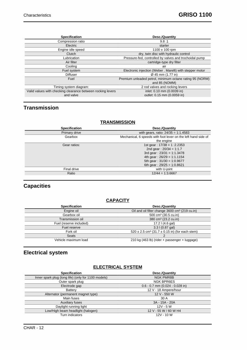
Specification Desc./QuantityCompression ratio 9.8 :1
Electric starterEngine idle speed 1100 ± 100 rpm
Clutch dry, twin disc with hydraulic controlLubrication Pressure-fed, controlled by valves and trochoidal pump
Air filter cartridge-type dry filterCooling air
Fuel system Electronic injection (Weber . Marelli) with stepper motorDiffuser Ø 45 mm (1.77 in)
Fuel Premium unleaded petrol, minimum octane rating 95 (NORM)and 85 (NOMM)
Timing system diagram: 2 rod valves and rocking leversValid values with checking clearance between rocking levers
and valveinlet: 0.10 mm (0.0039 in)
outlet: 0.15 mm (0.0059 in)
Transmission
TRANSMISSIONSpecification Desc./QuantityPrimary drive with gears, ratio: 24/35 = 1:1.4583
Gearbox Mechanical, 6 speeds with foot lever on the left hand side ofthe engine
Gear ratios: 1st gear : 17/38 = 1 :2.23532nd gear : 20/34 = 1:1.7
3rd gear : 23/31 = 1:1.34784th gear : 26/29 = 1:1.11545th gear : 31/30 = 1:0.96776th gear : 29/25 = 1:0.8621
Final drive with U-jointRatio 12/44 = 1:3.6667
Capacities
CAPACITYSpecification Desc./Quantity
Engine oil Oil and oil filter change 3600 cm³ (219 cu.in)Gearbox oil 500 cm³ (30.5 cu.in)
Transmission oil 380 cm³ (23.2 cu.in)Fuel (reserve included) 17.2 l (4.6 gal)
Fuel reserve 3.3 l (0.87 gal)Fork oil 520 ± 2.5 cm³ (31.7 ± 0.15 in) (for each stem)Seats 2
Vehicle maximum load 210 kg (463 lb) (rider + passenger + luggage)
Electrical system
ELECTRICAL SYSTEMSpecification Desc./Quantity
Inner spark plug (long life) (only for 1100 models) NGK PMR8BOuter spark plug NGK BPR6ES
Electrode gap 0.6 - 0.7 mm (0.024 - 0.028 in)Battery 12 V - 18 Ampere/hour
Alternator (permanent magnet type) 12 V - 550 WMain fuses 30 A
Auxiliary fuses 3A - 15A - 20ADaylight running light 12V - 5 W
Low/High beam headlight (halogen) 12 V - 55 W / 60 W H4Turn indicators 12V - 10 W
Characteristics GRISO 1100
CHAR - 12
Specification Desc./QuantityRear daylight running light/stop light LED
Dashboard lighting LEDLicense plate light 12V - 5 W
Turn indicator warning light LEDNeutral gear warning light LEDAlarm-shift warning light LED
Side stand down warning light LEDLow fuel warning light LED
High beam warning light LEDOil pressure warning light LED
Frame and suspensions
CHASSISSpecification Desc./Quantity
Type Double cradle, high strength steel tube chassisTrail 108 mm (4.25 in)
Headstock angle 26° 30'Front: Hydraulic telescopic fork, Ø 43 mm (1.69 in), adjustable in
spring preloading, hydraulic rebound and compression damp-ing.
Wheel travel 120 mm (4.72 in)Rear single arm with progressive linkage, single shock absorber with
spring preload, hydraulic compression and rebound dampingadjustment.
Wheel travel 110 mm (4.33 in)
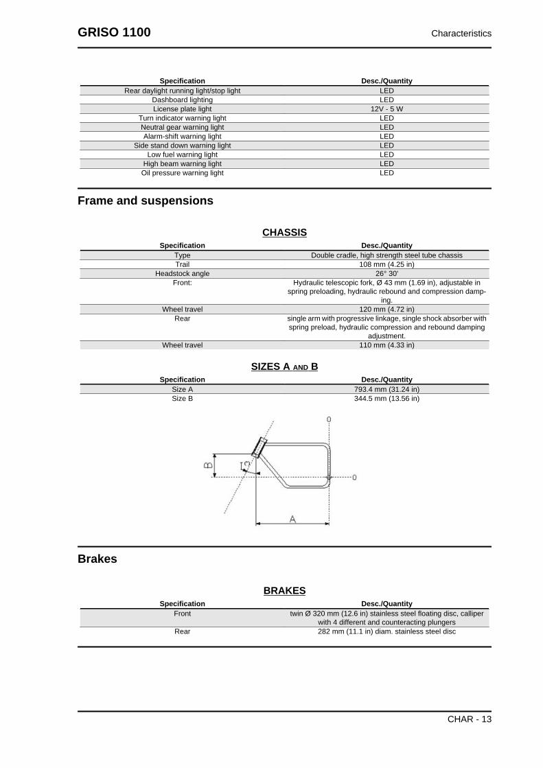
SIZES A AND BSpecification Desc./Quantity
Size A 793.4 mm (31.24 in)Size B 344.5 mm (13.56 in)
Brakes
BRAKESSpecification Desc./Quantity
Front twin Ø 320 mm (12.6 in) stainless steel floating disc, calliperwith 4 different and counteracting plungers
Rear 282 mm (11.1 in) diam. stainless steel disc
GRISO 1100 Characteristics
CHAR - 13

Wheels and tyres
WHEELS AND TYRESSpecification Desc./Quantity
Type hollow 3-spoke rim in chilled cast aluminium alloyFront wheel rim 3.50" x 17"Rear wheel rim 5.50" x 17"
Tyres METZELER Rennsport;MICHELIN Pilot Power;
DUNLOP D208 RRPIRELLI Diablo Corsa;
Front 120/70 - ZR 17" 58 WInflation pressure (front) 2.3 bar (230 kPa) (33.4 PSI)
Inflation pressure with passenger (front) 2.3 bar (230 kPa) (33.4 PSI)Rear 180/55 - ZR 17" 73 W
Inflation pressure (rear) 2.5 bar (250 kPa) (36.3 PSI)Inflation pressure with passenger (rear) 2.7 bar (270 kPa) (39.1 PSI)
Tightening Torques
HEADSName Torque in Nm
Oil cap (2) 25 Nm (18.44 lbf ft)Exhaust system stud bolt (4) 10 Nm (7.38 lbf ft) - Loctite 648
Rocking lever support nut - M10x1.5 (8) 15 Nm (11.06 lbf ft) + 90º + 90ºRocking lever nut (4) 10 Nm (7.38 lbf ft)
Set screw - TE M6x16 (4) 10 Nm (7.38 lbf ft)Head cover screw - M6x25 (16) 10 Nm (7.38 lbf ft)
Head fixing screw (4) 15 Nm (11.06 lbf ft) + 90ºOil temperature sensor 11 Nm (8.11 lbf ft) - Loctite 243
Oil temperature sensor container 11 Nm (8.11 lbf ft) - Loctite 601Outer Spark plugs 30 Nm (22.13 lbf ft) - MolikoteInner spark plugs 15 Nm (11.06 lbf ft) - Molikote
CRANKCASEName Torque in Nm
Crankcase stud bolt - cylinder (8) 25 Nm (18.44 lbf ft)Transmission side flange stud bolt - M8x66 (3) 35 Nm (25.81 lbf ft)Transmission side flange stud bolt - M8x75 (2) 35 Nm (25.81 lbf ft)
Crankshaft flange screw - TE M8x25 (14) 25 Nm (18.44 lbf ft)Timing system cover screw - TCEI M8x55 (4) 25 Nm (18.44 lbf ft)
Timing system cover screw - TCEI M6x30 (10) 10 Nm (7.38 lbf ft)Oil vapour union screw - TCEI M6x20 (2) 10 Nm (7.38 lbf ft)
Timing system outer cover screw - TCEI M6x16 (4) 10 Nm (7.38 lbf ft)Screw TSPEI M4x8 (2) 5 Nm (3.69 lbf ft) - Loctite 243TCEI M6x40 Screw (2) 10 Nm (7.38 lbf ft)
Timing sensor - TCEI M5x12 (2) 6 Nm (4.42 lbf ft)Crankcase stud bolts - chassis (4) 40 Nm (29.5 lbf ft) - Loctite 601
OIL SUMPName Torque in Nm
Oil radiator pipe fitting on sump (2) 20 Nm (14.75 lbf ft)Oil pipe on sump 20 Nm (14.75 lbf ft)
Oil sump lower screw - TCEI M6x30 (4) 10 Nm (7.38 lbf ft)Oil sump screw - TCEI M6x55 (14) 10 Nm (7.38 lbf ft)Oil sump screw - TCEI M6x60 (2) 10 Nm (7.38 lbf ft)
Oil drainage plug - M10x1 (1) 20 Nm (14.75 lbf ft)Oil filter (1) 15 Nm (11.06 lbf ft)
Oil filter fitting (1) 40 Nm (29.5 lbf ft) - Loctite 243Oil pipe in sump 20 Nm (14.75 lbf ft) - Loctite 648Thermostat cap 40 Nm (29.5 lbf ft)
Characteristics GRISO 1100
CHAR - 14

Name Torque in NmPressure-relief plug 40 Nm (29.5 lbf ft)
Oil intake filter fixing screw - TCEI M6x16 (1) 10 Nm (7.38 lbf ft) - Loctite 648
OIL PUMPName Torque in Nm
Oil pump fixing screw - TBEI M6x30 (3) 10 Nm (7.38 lbf ft) - Loctite 243Oil pump gear nut - M10x1.25 (1) 20 Nm (14.75 lbf ft)
Oil delivery pipe screw (1) 17 Nm (12.54 lbf ft)Oil pressure sensor 45 Nm (33.19 lbf ft)
TIMING SYSTEMName Torque in Nm
Camshaft flange screw - TE M6x20 (3) 10 Nm (7.38 lbf ft)Timing system gear nut on camshaft - M18 (1) 150 Nm (110.63 lbf ft)
Timing system gear nut on crankshaft - M25 (1) 120 Nm (88.51 lbf ft)Camshaft support screw on timing system cover - TCEI M4x10
(4)5 Nm (3.69 lbf ft) - Loctite 243
Belt tension 50 Nm (36.88 lb ft)
GENERATORName Torque in Nm
Alternator fixing screw - TCEI M8x45 (1) 22 Nm (16.23 lbf ft)Alternator fixing nut - M10x1.5 (1) 30 Nm (22.13 lbf ft)
Alternator pulley nut on crankshaft - M16 (1) 80 Nm (59 lbf ft) - Loctite 243
CRANKSHAFT - FLYWHEELName Torque in Nm
Start-up crown fixing screw on flywheel (8) 18 Nm (13.28 lbf ft) - Loctite 243Connecting rod screw (4) - pre-tightening 40 Nm (29.5 lbf ft)Connecting rod screw (4) - final tightening 80 Nm (59 lbf ft)
Flywheel fixing screw on crankshaft - M8x25 (6) 42 Nm (30.98 lbf ft) - Loctite 243
GEARName Torque in Nm
Gear shift cable lever nut 10 Nm (7.38 lbf ft)Gear shift tie rod lever nut on gear pre-selector 10 Nm (7.38 lbf ft)
Gearbox to crankcase fixing nut - M8 (5) 20 Nm (14.75 lbf ft)TE flanged screw fixing gearbox to crankcase - M8x45 (1) 20 Nm (14.75 lbf ft)
Oil cap M18x1.5 (1) 28 Nm (20.65 lbf ft)Breather cap (1) 8 Nm (5.9 lbf ft)
Gear in neutral sensor (1) 10 Nm (7.38 lbf ft)Oil drainage plug - M10x1 (1) 24 Nm (17.7 lbf ft)Transmission shaft ring nut (1) 100 Nm (73.76 lbf ft)
CHASSIS TO ENGINE UNITName Torque in Nm
M6x40 TCEI DA screw 8 -12 NmReduction 20 Nm
FUEL SUPPLY CONTROL UNITName Torque in Nm
M5x12 TCEI screw 6 -7 NmStainless M5x16 TBEI flanged screw 6 -7 Nm
M6x25 TCEI DA screw 8 -12 Nm
CHASSISName Torque in Nm
Front engine to chassis retainer 80 NmTransmission to chassis retainer (M12x250 + M12x230) 50 Nm
Right fixing plate - transmission retainer 25 Nm
GRISO 1100 Characteristics
CHAR - 15

Name Torque in NmPlate clamp - Blow-by retainer 10 Nm
Coil plate retainer 10 NmElectronic control unit retainer 10 Nm
Bushings to electronic control unit retainer 10 NmRetainer for tank to chassis rear support rubber rings Manual
Filter casing fixing bolts 10 NmLeft and right footrest plate to chassis upper retainer 25 NmLeft and right footrest plate to chassis lower retainer 18 Nm
Brake switch on plate retainer ManualPlate ring to plate retainer 6 Nm
Retainer for cable guide on right footrest plate 6 Nm
FOOTRESTS AND LEVERSName Torque in Nm
Footrest rubber retainer 10 NmRider footrest sliding pin - M8 25 Nm
Passenger footrest support to lateral plates retainer 38 NmRider heelrest to plates retainer 6 Nm
Passenger heelrest retainer 3 NmRod retainer (nut) 10 Nm
Gear shift lever / brake pin retainer 10 NmGear shift lever / pre-selector retainer 10 NmGear shift lever - brake pin retainer 15 Nm
SIDE STANDName Torque in Nm
Stand plate to engine upper retainer 50 NmStand plate to engine lower retainer 25 Nm
Side stand retainer pin 10 NmSwitch fixing screw 10 Nm
Lock nut 30 NmStand cable guide to engine retainer 50 Nm
Lateral lever arm retainer 10 Nm
SWINGARMName Torque in Nm
Swingarm on bushing clamp retainer 10 NmSwingarm on bevel gear pair retainer 50 Nm
Reaction rod to bevel gear pair retainer 50 NmReaction rod to chassis retainer 50 Nm
Swingarm bolt to swingarm retainer 60 NmPreloading bushing to swingarm bolt retainer 10 Nm
FRONT SUSPENSIONName Torque in Nm
Tube lock plate to steering base retainer 6 NmFork stem on upper plate retainer 18 Nm
Upper and lower screws fixing fork stem on lower plate 22 NmCentral screw fixing fork stem on lower plate 20 Nm
Headstock ring nut 40 NmHeadstock counter ring nut manual + 90 degrees
Upper yoke fixing cap 100 NmFork hubs closing 25 Nm
REAR SUSPENSIONName Torque in Nm
Shock absorber to chassis retainer - 8.8 50 NmDouble connecting rod/shock absorber retainer - 10.9 40 Nm
Single connecting rod/double connecting rod retainer - 10.9 50 NmSingle connecting rod to chassis retainer - 8.8 50 Nm
Double connecting rod/swingarm retainer - 10.9 50 Nm
Characteristics GRISO 1100
CHAR - 16

AIR FILTER CASINGName Torque in Nm
Blow-by expansion tank spacer to engine retainer 10 NmBlow-by expansion tank to spacer retainer 10 Nm
Filter housing to chassis retainer 10 Nm
EXHAUSTName Torque in Nm
Exhaust pipe to engine retainer 25 NmSilencer to chassis connecting pipe retainer 25 Nm
Silencer to footrest support retainer 25 NmProtection to connecting pipe retainer 10 Nm
Lambda probe retainer 38 NmClamp retainer 10 Nm
FRONT WHEELName Torque in Nm
Wheel pin nut 80 NmDisc retainer 30 Nm
REAR WHEELName Torque in Nm
Disc retainer 25 NmRear wheel retainer 10.9 110 Nm
FRONT BRAKING SYSTEMName Torque in Nm
Front brake right and left calliper retainer 50 Nm
REAR BRAKING SYSTEMName Torque in Nm
Rear brake calliper retainer 50 NmRear brake fluid reservoir retainer 3 Nm
Rear brake fluid reservoir support to plate retainer 10 NmRear brake rod lock nut manual
Brake pump retainer 10 Nm
HANDLEBAR AND CONTROLSName Torque in Nm
Retainer for handlebar lower U-bolts on steering upper plate 50 NmRetainer for handlebar upper U-bolts 25 NmAnti-vibration counterweight fastener 10 Nm
Brake pump and clutch U-bolts retainer 10 NmRight and left light switch retainer 1.5 Nm
Clutch control cylinder to gear retainer 10 NmRear-view mirror Manual
ELECTRICAL SYSTEMName Torque in Nm
Coil retainer 2 NmHorn retainer 15 Nm
Odometer sensor on bevel gear pair retainer 3 Nm
INSTRUMENT PANEL AND LIGHTSName Torque in Nm
Instrument panel support to light support retainer 10 NmInstrument panel support to fork upper plate retainer 10 Nm
Instrument panel retainer 3 NmLight support to fork lower plate retainer 25 Nm
GRISO 1100 Characteristics
CHAR - 17
Name Torque in NmRetainer for front and rear arrows 10 Nm
Headlamp retainer 15 NmRear light to tail clamp retainer 3 Nm
FUEL PUMP FLANGEName Torque in Nm
Pump support to tank retainer 6 NmTank breather joint 6 Nm
FUEL TANKName Torque in Nm
Filler to tank retainer 5 NmCap ring nut to tank retainer 5 Nm
Screws on cap ring nut (aesthetic) 5 NmTank to chassis front retainer 10 Nm
Battery housing and tank to chassis rear retainer 6 Nm
CHASSIS / FAIRINGS (FRONT)Name Torque in Nm
Front mudguard retainer 6 NmControl unit protection retainer 6 Nm
Deflectors to chassis front upper retainer ManualDeflectors to chassis front lower retainer Manual
Deflectors to chassis rear retainer ManualRetainer fixing the deflectors to deflector clamp Manual
CHASSIS/ FAIRINGS (REAR)Name Torque in Nm
Retroreflector to support retainer 4 NmRetroreflector support to license plate holder retainer 4 Nm
License plate holder and light support retainer 4 NmLicense plate holder to lower clamp retainer manualTail section to chassis lower clamp retainer 25 Nm
Fuse bracket and relay support retainer 4 Nm
FINISHINGSName Torque in Nm
Ignition lock retainer - shear head screw - Nm
Overhaul data
Assembly clearances
Cylinder - piston assy.
Measurement of the cylinder diameter must be done at three heights, turning the dial gauge 90°.
Check the clearance between the cylinders and pistons; if it exceeds the value specified, it is necessary
to replace cylinders and pistons.
The pistons of an engine must be balanced; a weight difference of up to 1.5 (0.0033 lb) is admitted.
ADMITTED MEASUREMENTSSpecification Desc./Quantity
cylinder diameter 92.000 - 92.020 mm (3.62204 - 3.62282 in)
Characteristics GRISO 1100
CHAR - 18
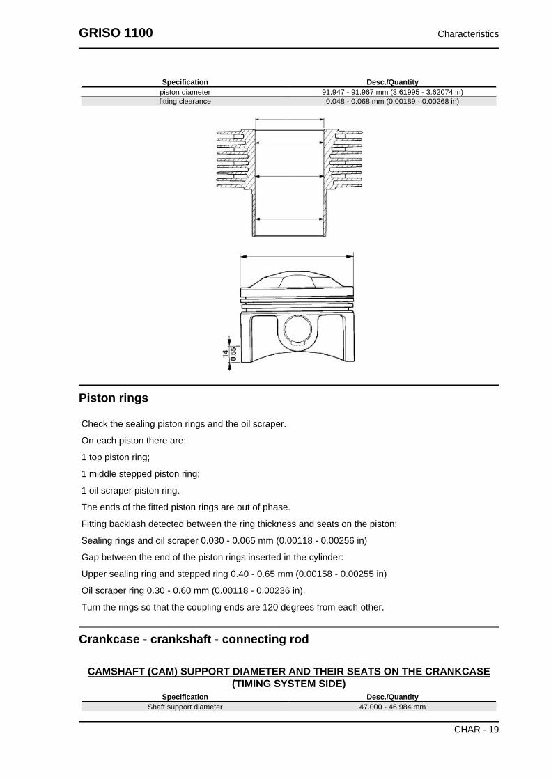
Specification Desc./Quantitypiston diameter 91.947 - 91.967 mm (3.61995 - 3.62074 in)fitting clearance 0.048 - 0.068 mm (0.00189 - 0.00268 in)
Piston rings
Check the sealing piston rings and the oil scraper.
On each piston there are:
1 top piston ring;
1 middle stepped piston ring;
1 oil scraper piston ring.
The ends of the fitted piston rings are out of phase.
Fitting backlash detected between the ring thickness and seats on the piston:
Sealing rings and oil scraper 0.030 - 0.065 mm (0.00118 - 0.00256 in)
Gap between the end of the piston rings inserted in the cylinder:
Upper sealing ring and stepped ring 0.40 - 0.65 mm (0.00158 - 0.00255 in)
Oil scraper ring 0.30 - 0.60 mm (0.00118 - 0.00236 in).
Turn the rings so that the coupling ends are 120 degrees from each other.
Crankcase - crankshaft - connecting rod
CAMSHAFT (CAM) SUPPORT DIAMETER AND THEIR SEATS ON THE CRANKCASE(TIMING SYSTEM SIDE)
Specification Desc./QuantityShaft support diameter 47.000 - 46.984 mm
GRISO 1100 Characteristics
CHAR - 19

Specification Desc./Quantity(1.85039 ÷ 1.84976 inch)
Seat diameter on base 47.025 - 47.050 mm(1.85137 ÷ 1.85236 inch )
fitting clearance 0.025 - 0.066 mm(0.00098 ÷ 0.00260 inch)
CAMSHAFT (CAM) SUPPORT DIAMETER AND THEIR SEATS ON THE CRANKCASE(FLYWHEEL SIDE)
Specification Desc./QuantityShaft support diameter 32.000 - 31.984 mm
(1.25984 ÷ 1.25921 inch)Seat diameter on base 32.025 - 32.050 mm
(1.26082 ÷ 1.26181 inch)fitting clearance 0.025 - 0.066 mm
(0.00098 ÷ 0.00260 inch)
TAPPET-SEAT COUPLING ON CRANKCASE DATA (PRODUCTION)Specification Desc./QuantitySeats diameter 22.021 - 22.000 mm
(0.86697 ÷ 0.86614 inch)Tappet external diameter 21.996 - 21.978 mm
(0.86598 ÷ 0.86527 inch)Fitting clearances 0.004 - 0.043 mm
(0.00016 ÷ 0.00169 in.)
Recommended products chart
RECOMMENDED PRODUCTSProduct Description Specifications
AGIP RACING 4T 10W-60 Engine oil SAE 10W - 60. As an alternative to rec-ommended fluids, use top branded oilswith performances that meet or exceedthe requirements of CCMC G-4 API. SG
specifications.AGIP GEAR SAE 80 W 90 Transmission oil -
AGIP GEAR MG/S SAE 85 W 90 Gearbox oil -AGIP FORK 7.5W Fork oil SAE 5W / SAE 20W
AGIP GREASE SM2 Lithium grease with molybdenum forbearings and other points needing lubri-
cation
NLGI 2
Neutral grease or petroleum jelly. Battery polesAGIP BRAKE 4 / BRAKE 5.1 Brake fluid As an alternative for recommended flu-
ids, use top branded fluids that meet orexceed the requirements of SAE J1703,NHTSA 116 DOT 4, ISO 4925 synthetic
fluid specifications.AGIP BRAKE 4 / BRAKE 5.1 Clutch fluid As an alternative for recommended flu-
ids, use top branded fluids that meet orexceed the requirements of SAE J1703,NHTSA 116 DOT 4, ISO 4925 synthetic
fluid specifications.NOTE
USE ONLY NEW BRAKE FLUID. DO NOT MIX DIFFERENT BRANDS OR TYPES OF OIL WITHOUTCHECKING THEIR BASE COMPATIBILITY.
Characteristics GRISO 1100
CHAR - 20

INDEX OF TOPICS
SPECIAL TOOLS S-TOOLS

SPECIAL TOOLSStores code Description06.94.86.00 belt tensioning tool
05.91.17.30 Front cover insertion cone
05.91.25.30 Gearbox opening
05.90.19.30 Inner spark plug removal
05.92.80.30 Piston ring clamp
05.92.72.30 Timing system cover sealing ring punch
Special tools GRISO 1100
S-TOOLS - 22
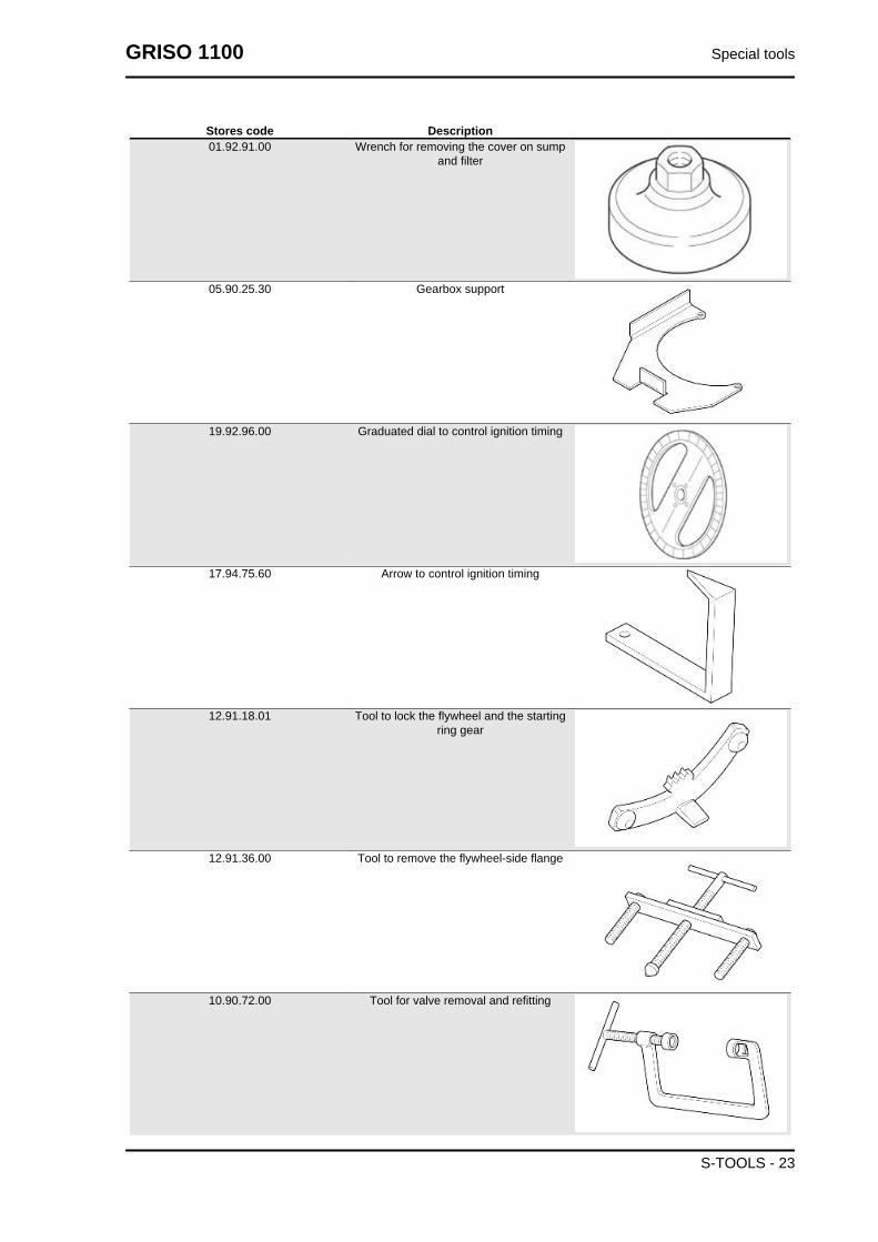
Stores code Description01.92.91.00 Wrench for removing the cover on sump
and filter
05.90.25.30 Gearbox support
19.92.96.00 Graduated dial to control ignition timing
17.94.75.60 Arrow to control ignition timing
12.91.18.01 Tool to lock the flywheel and the startingring gear
12.91.36.00 Tool to remove the flywheel-side flange
10.90.72.00 Tool for valve removal and refitting
GRISO 1100 Special tools
S-TOOLS - 23

Stores code Description30.90.65.10 Tool for clutch fitting
14.92.71.00 Tool to fit the sealing ring on the flywheel-side flange
12.91.20.00 Tool to fit the flywheel-side flange togeth-er with seal ring on the crankshaft
19.92.71.00 Tool to fit the seal ring on the flywheel-side flange
14.92.73.00 Tool for camshaft gear sealing
981006 Graduated dial hub
AP8140190 Tool for steering tightening
Special tools GRISO 1100
S-TOOLS - 24
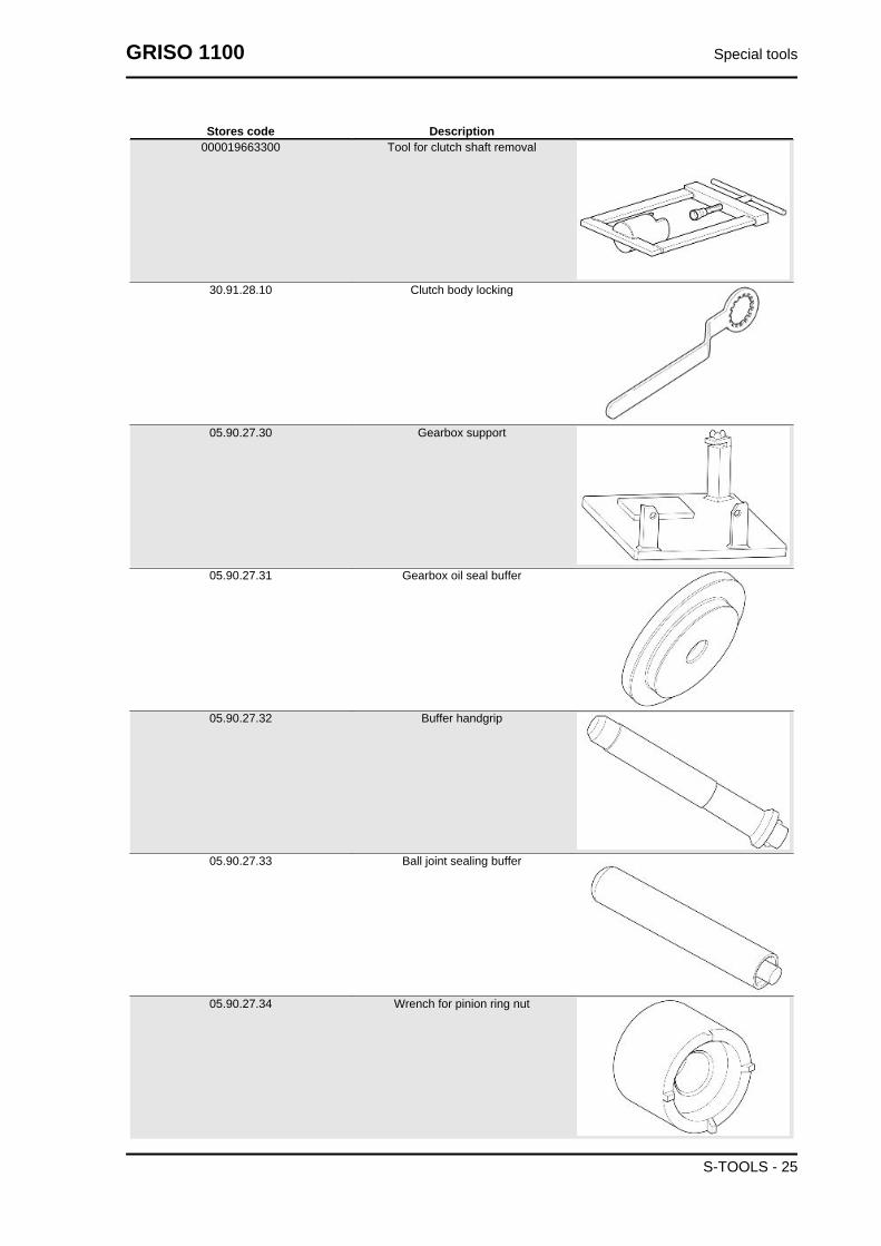
Stores code Description000019663300 Tool for clutch shaft removal
30.91.28.10 Clutch body locking
05.90.27.30 Gearbox support
05.90.27.31 Gearbox oil seal buffer
05.90.27.32 Buffer handgrip
05.90.27.33 Ball joint sealing buffer
05.90.27.34 Wrench for pinion ring nut
GRISO 1100 Special tools
S-TOOLS - 25

Stores code Description05.90.27.35 Pinion oil seal buffer
05.90.27.36 Bevel gear pair support
AP8140145 fitting tool for Ø 41 mm seal rings
AP8140146 Weight
AP8140147 Spacer tool
AP8140148 Spacer-piston separating plate
AP8140149 Protection for fitting operations
Special tools GRISO 1100
S-TOOLS - 26
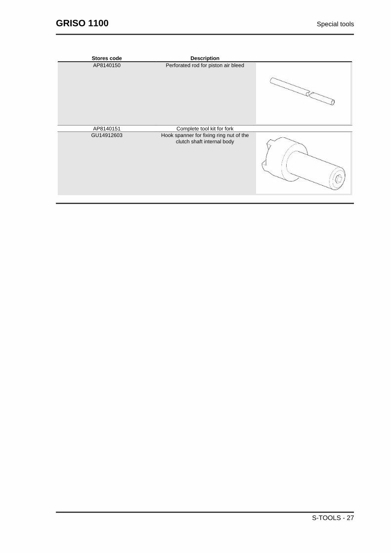
Stores code DescriptionAP8140150 Perforated rod for piston air bleed
AP8140151 Complete tool kit for forkGU14912603 Hook spanner for fixing ring nut of the
clutch shaft internal body
GRISO 1100 Special tools
S-TOOLS - 27

INDEX OF TOPICS
MAINTENANCE MAIN
Maintenance chartNOTE
CARRY OUT MAINTENANCE OPERATIONS AT HALF THE INTERVALS SPECIFIED IF THE VE-HICLE IS USED IN PARTICULAR RAINY OR DUSTY CONDITIONS, OFF ROAD OR FOR TRACKUSE.
AT EVERY START-UPAction
Engine oil pressure warning light - check and clean, adjust, grease or replace if necessary
BEFORE EACH RIDE AND EVERY 2000 KM (1250 MI)Action
Tyre pressure - AdjustBrake pad wear - Check and clean, adjust or replace if necessary
AFTER RUN-IN (1,500 KM (932 MI)Action
Exhaust pipe flange bolts - Check and clean, adjust, grease or replace if necessaryTransmission cables and controls - Check and clean, adjust, grease or replace if necessarySteering bearings and steering clearance - Check and clean, adjust, grease or replace if necessary.Disc brakes - Check and clean, adjust or replace if necessaryEngine oil filter - ReplaceFork - Check and clean, adjust and lubricateGeneral vehicle operation - Check and clean, adjust, grease or replace if necessary.Braking systems - Check and clean, adjust, grease or replace if necessaryLight circuit - Check and clean, adjust or replace if necessarySafety switches - Check and clean, adjust, grease or replace if necessaryGearbox oil - ChangeEngine oil - ChangeFinal transmission oil - ChangeTyres - Check and clean, adjust, grease or replace if necessaryTyre pressure - AdjustEngine revs at idle speed - Adjustment.Valve clearance adjustment - AdjustWheels - Check and clean, adjust, grease or replace if necessaryBolts, nuts and screws tightening - Check and clean, adjust, grease or replace if necessaryBattery terminals tightening - Check and clean, adjust, grease or replace if necessaryCylinder synchronisation - Check and clean, adjust, grease or replace if necessarySuspensions and setting - Check and clean, adjust, grease or replace if necessaryBrake pad wear - Check and clean, adjust or replace if necessary
EVERY 4 YEARSAction
Fuel pipes - ReplaceBrake pipes - Replacement
EVERY 5000 KM (3125 MI) - IF THE VEHICLE IS USED FOR RACINGAction
Outer spark plugs - ReplaceEngine oil filter - ReplaceEngine oil - ChangePurge fluid present in oil drainage pipe from the filter housing - CleanClutch wear - Check and clean, adjust, grease or replace if necessary
EVERY 10,000 KM (6250 MILES) OR 12 MONTHSAction
Outer spark plugs - ReplaceIdle mixture (CO) - Check and clean, adjust, grease or replace if necessaryTransmission cables and controls - Check and clean, adjust, grease or replace if necessary
GRISO 1100 Maintenance
MAIN - 29
ActionSteering bearings and steering clearance - Check and clean, adjust, grease or replace if necessary.Wheel bearings - Check and clean, adjust, grease or replace if necessaryDisc brakes - Check and clean, adjust or replace if necessaryAir filter - Check and clean, adjust, grease or replace if necessaryEngine oil filter - ReplaceGeneral vehicle operation - Check and clean, adjust, grease or replace if necessary.Braking systems - Check and clean, adjust, grease or replace if necessaryGearbox oil - ChangeEngine oil - ChangeFinal transmission oil - ChangeValve clearance adjustment - AdjustWheels - Check and clean, adjust, grease or replace if necessaryBolts, nuts and screws tightening - Check and clean, adjust, grease or replace if necessaryCylinder synchronisation - Check and clean, adjust, grease or replace if necessaryPurge fluid present in oil drainage pipe from the filter housing - CleanFuel pipes - Check and clean, adjust, grease or replace if necessaryBrake pipes - Check and clean, adjust, grease or replace if necessaryClutch wear - Check and clean, adjust, grease or replace if necessary
AFTER THE FIRST 10,000 KM (6,250 MILES) AND THEN AFTER EVERY 20,000 KM (12,500MILES)Action
Fork oil - ChangeFork oil seals - Replace
EVERY 20000 KM (12500 MILES) OR 24 MONTHSAction
Inner spark plugs - ReplaceAlternator belt - Adjust; EVERY 50,000 km (31,050 mi)Air filter - ReplaceFork - Check and clean, adjust and lubricateBrake fluid - changeSuspensions and setting - Check and clean, adjust, grease or replace if necessaryBrake pad wear - Check and clean, adjust or replace if necessary
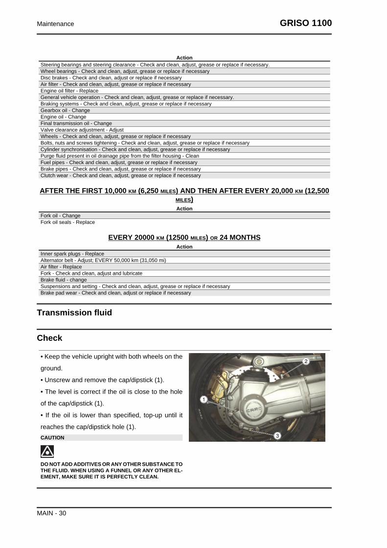
Transmission fluid
Check
• Keep the vehicle upright with both wheels on the
ground.
• Unscrew and remove the cap/dipstick (1).
• The level is correct if the oil is close to the hole
of the cap/dipstick (1).
• If the oil is lower than specified, top-up until it
reaches the cap/dipstick hole (1).CAUTION
DO NOT ADD ADDITIVES OR ANY OTHER SUBSTANCE TOTHE FLUID. WHEN USING A FUNNEL OR ANY OTHER EL-EMENT, MAKE SURE IT IS PERFECTLY CLEAN.
Maintenance GRISO 1100
MAIN - 30

ReplacementCAUTION
THE UNIT MUST BE HOT WHEN THE OIL IS CHANGED AS UNDER SUCH CONDITIONS OIL ISFLUID AND THEREFORE EASY TO DRAIN.NOTE
RIDE SOME km (miles) TO WARM UP ENGINE OIL• Place a container with + 400 cm³ (25 cu in) capacity under the drainage plug (3).
• Unscrew and remove the drainage plug (3).
• Unscrew and remove the breather cap (2).
• Drain the oil into the container; allow several minutes for oil to drain out completely.
• Check and if necessary, replace the sealing washer of drainage plug (3).
• Remove any metal scrap attached to the drainage plug (3) magnet.
• Screw and tighten the drainage plug (3).
• Pour new oil through the fill opening (1) until it reaches the cap/dipstick hole (1).CAUTION
DO NOT ADD ADDITIVES OR ANY OTHER SUBSTANCE TO THE FLUID. WHEN USING A FUNNELOR ANY OTHER ELEMENT, MAKE SURE IT IS PERFECTLY CLEAN.
• Screw and tighten the caps (1 - 2).
Engine oil
CheckCAUTION
ENGINE MUST BE WARM TO CHECK ENGINE OIL LEVEL.NOTE
DO NOT LET THE ENGINE IDLE WITH THE VEHICLE AT STANDSTILL TO WARM UP THE ENGINEOIL AND REACH THE OPERATING TEMPERATURE OF ENGINE OIL. OIL IS BEST CHECKEDAFTER RUNNING FOR ABOUT 15 KM (10 miles).
• Shut off the engine.
• Keep the vehicle upright with the two wheels on the ground.
• Unscrew and remove the dipstick (1).
• Clean the dipstick (1).
• Reinsert the dipstick (1) into the opening but do not screw it.
GRISO 1100 Maintenance
MAIN - 31

• Remove the dipstick (1).
• Check oil level on the dipstick (1).
• The oil level is correct when it close to the "MAX" mark.
MAX = maximum level
MIN = minimum level
Add engine oil if required:
• Unscrew and remove the dipstick (1).
• Top-up with engine oil until it goes above the minimum level marked "MIN".CAUTIONDO NOT ADD ADDITIVES OR ANY OTHER SUBSTANCE TOTHE FLUID. WHEN USING A FUNNEL OR ANY OTHER EL-EMENT, MAKE SURE IT IS PERFECTLY CLEAN.
ReplacementNOTE
HOT OIL IS MORE FLUID AND WILL DRAIN OUT MORE EASILY AND COMPLETELY.• Place a container with + 4000 cm³ (245
cu in) capacity under the drainage plug
(2).
• Unscrew and remove the drainage
plug (2).
• Unscrew and remove the filler plug (3).
• Drain the oil into the container; allow
several minutes for oil to drain out com-
pletely.
• Check and if necessary, replace the
sealing washers of drainage plug (2).
• Remove any metal scrap attached to
the drainage plug (2) magnet.
Maintenance GRISO 1100
MAIN - 32

• Screw and tighten the drainage plug
(2).
• Pour new oil until it goes above the
minimum level marked "MIN".
Engine oil filter
• Unscrew and remove the engine oil fil-
ter from its seat.NOTENEVER REUSE AN OLD FILTER.
• Spread a thin layer of oil on the sealing ring of the new engine oil filter.
• Fit and screw the new oil filter in its seat.
Gearbox Oil
Inspection
CHECKING AND TOPPING UPCAUTION
ENGINE MUST BE WARM TO CHECK GEARBOX OIL LEVEL.NOTE
DO NOT LET THE ENGINE IDLE WITH THE VEHICLE AT STANDSTILL TO WARM UP THE ENGINEOIL AND REACH THE OPERATING TEMPERATURE OF ENGINE OIL. OIL IS BEST CHECKEDAFTER RUNNING FOR ABOUT 15 KM (10 miles).
• Shut off the engine.
• Keep the vehicle upright with both
wheels on the ground.
• Undo and remove the dipstick opening
(1) located on the right side of the gear-
box.
• The level is correct if the oil is close to
the hole of the dipstick (1).
If necessary:
GRISO 1100 Maintenance
MAIN - 33

• Top-up with oil until it reaches the dip-
stick opening (1).CAUTIONDO NOT ADD ADDITIVES OR ANY OTHER SUBSTANCE TOTHE FLUID. WHEN USING A FUNNEL OR ANY OTHER EL-EMENT, MAKE SURE IT IS PERFECTLY CLEAN.
ReplacementNOTE
HOT OIL IS MORE FLUID AND WILL DRAIN OUT MORE EASILY AND COMPLETELY.
• Place a container with suitable capacity under the
drainage plug (2).
• Unscrew and remove the drainage plug (2).
• Unscrew and remove the filler cap (1).
• Drain the oil into the container; allow several mi-
nutes for oil to drain out completely.
• Check and replace, if necessary, the sealing
washers of drainage plug (2).
• Remove any metal scrap attached to the drain-
age plug (2) magnet.
• Screw and tighten the drainage plug (2).
• Pour in new oil until it reaches the dipstick open-
ing (1).
• Tighten the filler cap (1).CAUTIONDO NOT ADD ADDITIVES OR ANY OTHER SUBSTANCE TOTHE FLUID. WHEN USING A FUNNEL OR ANY OTHER EL-EMENT, MAKE SURE IT IS PERFECTLY CLEAN.
Air filter
• Disconnect the air temperature sensor
connector.
Maintenance GRISO 1100
MAIN - 34
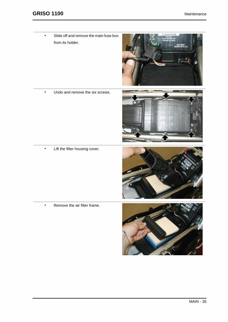
• Slide off and remove the main fuse box
from its holder.
• Undo and remove the six screws.
• Lift the filter housing cover.
• Remove the air filter frame.
GRISO 1100 Maintenance
MAIN - 35
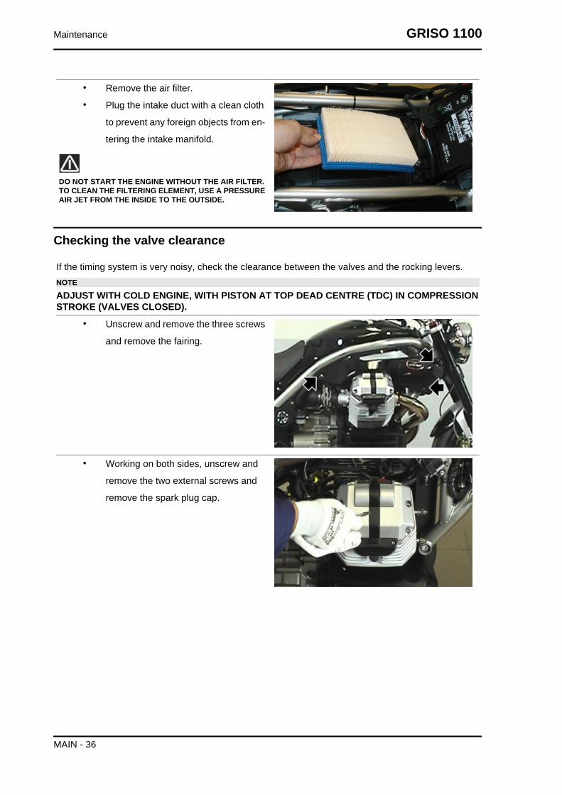
• Remove the air filter.
• Plug the intake duct with a clean cloth
to prevent any foreign objects from en-
tering the intake manifold.
DO NOT START THE ENGINE WITHOUT THE AIR FILTER.TO CLEAN THE FILTERING ELEMENT, USE A PRESSUREAIR JET FROM THE INSIDE TO THE OUTSIDE.
Checking the valve clearance
If the timing system is very noisy, check the clearance between the valves and the rocking levers.NOTE
ADJUST WITH COLD ENGINE, WITH PISTON AT TOP DEAD CENTRE (TDC) IN COMPRESSIONSTROKE (VALVES CLOSED).
• Unscrew and remove the three screws
and remove the fairing.
• Working on both sides, unscrew and
remove the two external screws and
remove the spark plug cap.
Maintenance GRISO 1100
MAIN - 36
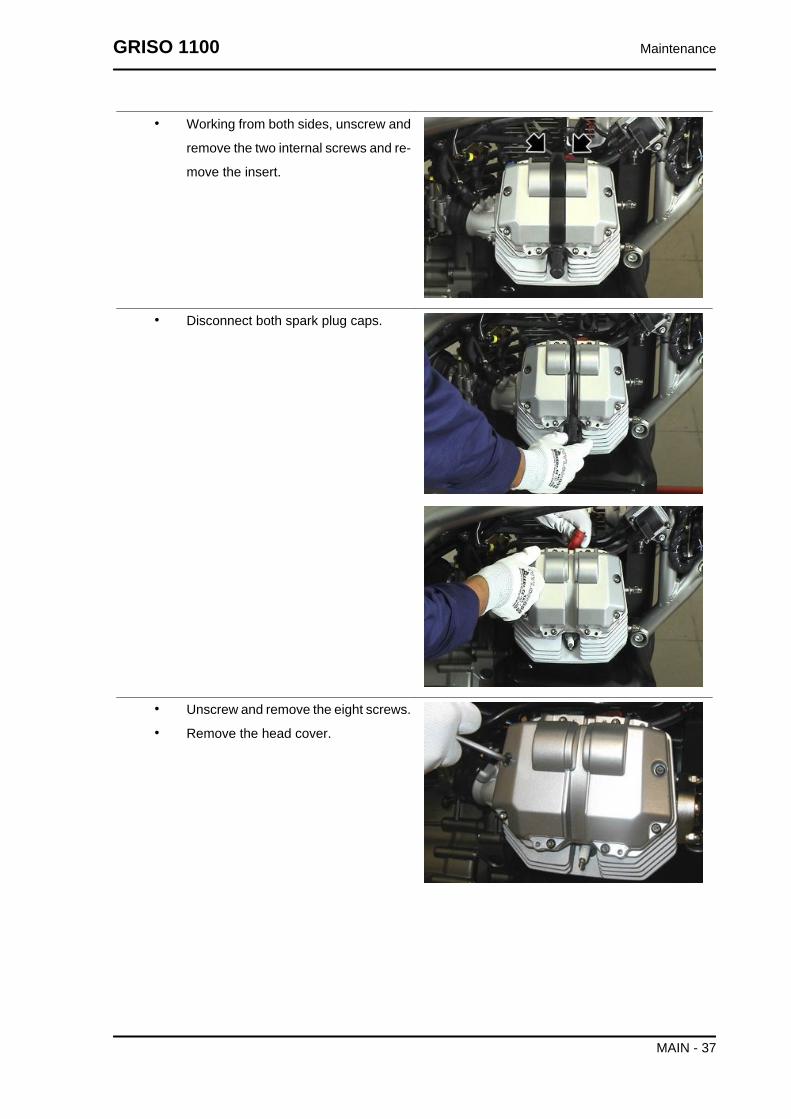
• Working from both sides, unscrew and
remove the two internal screws and re-
move the insert.
• Disconnect both spark plug caps.
• Unscrew and remove the eight screws.
• Remove the head cover.
GRISO 1100 Maintenance
MAIN - 37

• Loosen the nut (1).
• Use a screwdriver on the set screw (2)
until the following clearances are ob-
tained:
Inlet valve: 0.10 mm (0.0039 in)
Outlet valve: 0.15 mm (0.0059 in)
• The measurement must be done using
a thickness gauge (3).CAUTIONIF CLEARANCE IS LARGER THAN RECOMMENDED, THETAPPETS WILL BE NOISY. OTHERWISE, THE VALVES DONOT CLOSE CORRECTLY, WHICH CAN LEAD TO PROB-LEMS SUCH AS:
• PRESSURE DROP;• ENGINE OVERHEAT;• VALVE BURN OUT, ETC.
Braking system
Level check
Brake fluid check
• Rest the vehicle on its stand.
• For the front brake, turn the handlebar fully to the right.
• For the rear brake, keep the vehicle upright so that the fluid in the reservoir is at the same
level with the plug.
• Make sure that the fluid level in the reservoir is above the "MIN" reference mark:
MIN = minimum level
MAX = maximum level
If the fluid does not reach at least the "MIN" reference mark:
• Check brake pads and disc for wear.
• If the pads and/or the disc do not need replacing, top-up the fluid.
Maintenance GRISO 1100
MAIN - 38

Top-up
Front brake:
• Unscrew the two screws (1) of the
brake fluid reservoir (2) using a Phillips
screwdriver.
• Lift and remove the cover (3) and
screws (1) as well.
• Remove the gasket (4).
Rear brake:
• Unscrew and remove the cap (5).
• Remove the gasket (6).
• Top-up the reservoir with brake fluid to
the correct level, which is between the
two "MIN" and "MAX" reference marks.
RISK OF BRAKE FLUID SPILLS. DO NOT OPERATE THEBRAKE LEVER WITH BRAKE FLUID RESERVOIR CAPLOOSENED OR REMOVED.CAUTION
AVOID PROLONGED AIR EXPOSURE OF THE BRAKEFLUID. BRAKE FLUID IS HYGROSCOPIC AND ABSORBSMOISTURE WHEN IN CONTACT WITH AIR. LEAVE THEBRAKE FLUID RESERVOIR OPEN ONLY FOR THE TIMENEEDED TO COMPLETE THE TOPPING UP PROCEDURE.
TO AVOID SPILLING FLUID WHILE TOPPING-UP, KEEPTHE TANK PARALLEL TO THE RESERVOIR EDGE (INHORIZONTAL POSITION).
DO NOT ADD ADDITIVES OR ANY OTHER SUBSTANCE TOTHE FLUID.
WHEN USING A FUNNEL OR ANY OTHER ELEMENT,MAKE SURE IT IS PERFECTLY CLEAN.
DO NOT EXCEED THE "MAX" LEVEL MARK WHEN TOP-PING UP.TOP-UP TO "MAX" LEVEL MARK ONLY WHEN BRAKEPADS ARE NEW. WHEN TOPPING UP DO NOT EXCEEDTHE "MAX" LEVEL MARK WHEN BRAKE PADS AREWORN AS YOU RISK SPILLING FLUID WHEN CHANGINGTHE BRAKE PADS.CHECK BRAKING EFFICIENCY. IN CASE OF EXCESSIVETRAVEL OF THE BRAKE LEVER OR POOR PERFORM-ANCE OF THE BRAKING SYSTEM, TAKE YOUR VEHICLETO AN Official Moto Guzzi Dealer, AS IT MAY BE NECES-SARY TO PURGE THE AIR IN THE SYSTEM.
GRISO 1100 Maintenance
MAIN - 39

Maintenance GRISO 1100
MAIN - 40

INDEX OF TOPICS
ELECTRICAL SYSTEM ELE SYS

Components arrangement
Key:
1 Coil
2 Instrument panel
3 Fuel pump
4 Injector
Electrical system GRISO 1100
ELE SYS - 42

5 Throttle valve potentiometer
6 Fall sensor
7 Rear light
8 Main fuses
9 Lambda probe
10 Battery
11 Starter motor
12 Intake air temperature sensor
13 Engine revolution sensor
14 Head temperature sensor
15 Engine control unit
16 Instrument panel air temperature sensor
17 Front headlamp
18 Alternator
19 Oil pressure sensor
20 Speed sensor
21 Auxiliary fuses
Electrical system installation
GRISO 1100 Electrical system
ELE SYS - 43

General wiring diagram
Key:
1 Multiple connectors
2 Diode pre-installation
3 Start-up relay
4 Clutch switch
5 Lights relay
Electrical system GRISO 1100
ELE SYS - 44

6 Right light switch
7 Condenser pre-installation
8 Horn
9 Left light switch
10 Instrument panel air temperature thermistor
11 Instrument panel
12 Instrument panel diagnosis
13 Key switch
14 Immobilizer aerial
15 Right rear turn indicator
16 Rear light (with LED)
17 Left rear turn indicator
18 License plate light
19 Rear stop switch
20 Front stop switch
21 (ECU) Diagnosis connector
22 Secondary fuses
23 Main fuses
24 Starter motor
25 Battery
26 -
27 Alternator
28 Main injection relay
29 Secondary injection relay
30 Oil pressure bulb
31 Gear in neutral switch
32 Lambda probe
33 Side stand switch
34 Fuel reserve sensor
35 Fuel pump
36 Intake air temperature thermistor
37 Head temperature thermistor
38 Automatic air
39 Throttle sensor
40 Right cylinder inner spark plug
41 Right cylinder outer spark plug
42 Left cylinder inner spark plug
43 Left cylinder outer spark plug
GRISO 1100 Electrical system
ELE SYS - 45

44 Right cylinder double coil
45 Left cylinder double coil
46 Right cylinder injector
47 Left cylinder injector
48 Speed sensor
49 Fall sensor
50 Flywheel pick up
51 Pick up cable shielding
52 ECU control unit
53 Left front turn indicator
54 Tail light bulb
55 Low-/high-beam light bulb
56 Front headlamp
57 Right front turn indicator
58 GPS attachment (if fitted)
Cable colour:
Ar orange
Az sky blue
B blue
Bi white
G yellow
Gr grey
M brown
N black
R red
Ro pink
V green
Vi purple
Checks and inspections
Dashboard
Diagnosis
Changing the CODE
If you know the code, just enter it and then a new code that will be automatically stored in the memory.
If the vehicle is new, the user code is: 00000
Electrical system GRISO 1100
ELE SYS - 46

Resetting the CODE
This function is used to set a new code when the old one is not available; in this case, at least two of
the programmed keys have to be inserted in the ignition lock.
After the first key has been inserted, the second one is requested with the following message:
INSERT KEY II
If the second key is not inserted within 20 seconds, the operation is finished.
After recognising the second key, the new code is required with the message:
ENTER NEW CODE
Once the operation is finished, the instrument panel goes back to the SET-UP menu.
DIAGNOSIS
Access to this menu (diagnosis functions), for the technical service only, after requesting a service code.
It will read: ENTER SERVICE CODE. The code for Griso 1100 is: 12425
The functions in this menu are
• Exit
• ECU Diagnosis
• Instrument panel errors
• Delete errors
• Reset Service
• Update
• Key change
• km / miles
ECU ERRORS
The instrument panel receives only the current errors from the control unit.
Description Error code
Throttle Valve Error DC V DC ECU 10
Throttle Valve Error DC Gnd ECU 11
Engine Temperature Error DC V DC ECU 14
Engine Temperature Error DC Gnd ECU 15
Air Temperature Error DC V DC ECU 16
Air Temperature Error DC Gnd ECU 17
Low Battery Error ECU 20
Lambda Probe Error ECU 21
Coil 1 Error DC V DC ECU 22
Coil 1 Error DC Gnd ECU 23
Coil 2 Error DC V DC ECU 24
Coil 2 Error DC Gnd ECU 25
Injector 1 Error DC V DC ECU 26
Injector 1 Error DC Gnd ECU 27
GRISO 1100 Electrical system
ELE SYS - 47

Injector 2 Error DC V DC ECU 30
Pump Relay Error ECU 36
Local Loopback Error ECU 37
Start-up Remote Error DC V DC ECU 44
Remote Error Start-up DC Gnd ECU 45
Canister Error DC V DC ECU 46
Canister Error DC Gnd ECU 47
Battery Error Hig ECU 50
Generic ECU Error ECU 51
Signal Panel Error ECU 54
Self-adaptability Value Error ECU 55
Vehicle Speed Error ECU 56
Stepper Error AC ECU 60
Stepper Error DC V DC ECU 61
Stepper Error DC Gnd ECU 62
Not recognised error ECU 00
INSTRUMENT PANEL ERRORS
In this mode a chart is displayed showing potential errors in the immobilizer and its sensors.
This is the error decoding chart:
Description: Immobilizer failure: Key code read but not recognised. Error code: DSB 01
Description: Immobilizer failure: Key code not read (Key not inserted or transponder broken) Error code:
DSB 02
Description: Immobilizer failure: Aerial not working (Open or short-circuited). Error code: DSB 03
Description: Immobilizer failure: Internal controller failure. Error code: DSB 04
Description: - Error code: DSB 05
Description: Air temperature sensor failure. Error code: DSB 06
Description: Oil sensor failure. Error code: DSB 07
Description: Oil pressure failure. Error code: DSB 08
The instrument panel keeps all previous errors stored in its memory.
DELETE ERRORS
This option deletes instrument panel errors only, a further confirmation is requested.
Electrical system GRISO 1100
ELE SYS - 48

INSTRUMENT PANEL SOFTWARE UPGRADE
This function is used to program the instrument
panel again with a new software through Axone.
The Display reads: "Instrument panel disconnec-
ted. Now connect the diagnosis instrument"; the
instrument panel will connect normally after the
key is extracted-inserted.
The white connector is placed under the saddle,
beside the fuse box, close to the diagnosis con-
nector for the injection system.
Use the Ditech connector in the Axone 2000 Apri-
lia-Moto Guzzi package to connect to the Axone
cable.
KEY CHANGE FUNCTION
This function can be used:
1) if one key is lost; the dealer can disable this key;
2) to activate up to 4 keys;
3) should a new key lock be necessary and thus program the new set of keys.
In the first phase the user code must be entered and, after confirming the inserted key (key I) has been
programmed, the other keys must be entered too.
The procedure finishes once the 4 keys have been programmed or after 20 seconds.
Should a new key lock be necessary, the procedure is: once the key is set to ON but the instrument
panel does not recognise it, the user code is requested: enter the user code.
Now enter MENU, DIAGNOSIS (entering the service code), KEY CHANGE and program the new keys.
Battery recharge circuit
Checking the stator
Single-phase generator with regulated voltage
Maximum load 40A (550W)
Charging voltage 14.2 - 14.8 V (5000 rpm)
GRISO 1100 Electrical system
ELE SYS - 49

Start-up system check
pick-up input about 100 A
level indicators
Petrol pump:
Input: 3.5 A (to be measured between pins 1 and
2 with 12V voltage)
Fuel level sensor:
Resistance (to be measured between pins 3 and
4)
250-300 Ohm with fuel level equal to 0 litre
100 Ohm with fuel level equal to 11.25 litres (20.43
pt)
10-20 Ohm with fuel level equal to 22.5 litres
(40.86 pt)
The low fuel warning light turns on with values over
230 Ohm.
In case there is anomaly on the fuel probe, the low fuel warning light flashes on the instrument panel.
The alarm warning light on the instrument panel does not light up and the word Service is not displayed.
Lights list
FRONT HEADLAMP
Tail light: 12V - 5W
Low-beam light: 12V - 55W
High-beam light: 12 V - 60 W H4
Electrical system GRISO 1100
ELE SYS - 50

REAR LIGHT
LED
Fuses
AUXILIARY FUSES
A - Stop, horn, coil, light relay (15 A).
B - Tail lights, license plate light, passing (15 A).
C - Fuel pump, coils, injectors, start-up relay (20
A).
D - Lambda burner, secondary injection relay coil,
start-up relay coil, speed sensor power supply,
ECU control unit power supply, engine kill (15 A).
E - Permanent positive, ECU power supply (3A).
F - "Tom - Tom" (3A) (if fitted)NOTETHERE ARE THREE SPARE FUSES (3, 15, 20 A).
MAIN FUSES
1 - From battery to voltage regulator (30 A).
2 - From battery to key and auxiliary fuses C - D
(30 A).NOTETHERE IS ONE SPARE FUSE.
GRISO 1100 Electrical system
ELE SYS - 51

Control unit
Model: Magneti Marelli IAW 5 AM2
Black connector pins
Pin Use
1 Not used
2 Not used
3 Ignition potentiometer signal
4 Not used
5 Engine temperature signal
6 Not used
7 Not used
8 Not used
9 Stepper motor (+)
10 Right cylinder coil control
11 Not used
12 Not used
13 Not used
14 Air temperature signal
15 Not used
16 Not used
17 Stepper motor (+)
18 Stepper motor (-)
19 Stepper motor (-)
20 5V power supply (NTC sensors)
21 Not used
22 Not used
23 Neutral sensor signal
24 Not used
25 Engine revolution sensor signal
26 Not used
27 Not used
28 Left cylinder injector control
29 Ignition potentiometer power supply
30 Not used
31 Not used
32 Ignition potentiometer negative
33 Not used
Electrical system GRISO 1100
ELE SYS - 52

34 Revolution sensor anti-jamming cable
35 Engine revolution sensor signal
36 Not used
37 Right cylinder injector control
38 Left cylinder coil control
Grey connector pins
Pin Use
1 Pin 85 ignition relay control
2 Not used
3 Not used
4 Power supply protected from instrument panel
5 Not used
6 Pin 86 auxiliary relay control
7 Immobilizer line
8 Pin 85 ignition relay control
9 Not used
10 Not used
11 Oxygen probe negative control
12 Not used
13 Not used
14 Not used
15 Not used
16 K line (diagnosis)
17 Power supply from main relay
18 Not used
19 Not used
20 CAN - H line (ccm/instrument panel)
21 Not used
22 Oxygen probe signal
23 Not used
24 Vehicle speed signal input
25 Not used
26 Not used
27 "Engine stop" signal input
28 Ignition signal input
29 CAN - L line (ccm/instrument panel)
30 Not used
31 Not used
GRISO 1100 Electrical system
ELE SYS - 53

32 Oxygen probe power supply
33 Clutch sensor signal
34 Not used
35 Fall sensor signal
36 Not used
37 Not used
38 Side stand sensor signal
Battery
12 V - 18 Ampere/hour
Speed sensor
Active inductive sensor
3-pin connector (Power supply - Signal-Earth con-
nection).
Electrical system GRISO 1100
ELE SYS - 54

Engine rpm sensor
Measures the engine revolution speed and each
cylinder timing in relation to the TDC
Inductive type sensor, with three-way connector:
• positive voltage pin;
• negative voltage pin: resistance from
650 to 720 Ohm (to be measured be-
tween pins 1 and 2);
• shielding pin.
Air gap value: (measure sensor length with a depth
gauge): 0.5 - 0.7 mm (0.0197 - 0.0276 in).
Throttle position sensor
Output voltage 0.55 - 4.4 V (variable depending on
the position of the throttle valve, to be measured
between pins C and A)
Engine temperature sensor
This sensor, 5V powered, features NTC specifications and sends the control unit a signal which varies
depending on temperature to help manage the stoichiometric ratios during engine speed adjustment.
ENGINE TEMPERATURE SENSOR RESISTANCESpecification Desc./Quantity
1 Resistance at -40 °C (-40 °F) 100.950 kOhm2 Resistance at -30 °C (-22 °F) 53.100 kOhm3 Resistance at -20 °C (-4 °F) 29.120 kOhm4 Resistance at -10 °C (14 °F) 16.600 kOhm5 Resistance at 0 °C (32 °F) 9.750 kOhm6 Resistance at +10 °C (50 °F) 5.970 kOhm7 Resistance at +20 °C (68 °F) 3.750 kOhm8 Resistance at +30 °C (86 °F) 2.420 kOhm9 Resistance at +40 °C (104 °F) 1.600 kOhm10 Resistance at +50 °C (122 °F) 1.080 kOhm11 Resistance at +60 °C (140 °F) 0.750 kOhm12 Resistance at +70 °C (158 °F) 0.530 kOhm13 Resistance at +80 °C (176 °F) 0.380 kOhm14 Resistance at +90 °C (194 °F) 0.280 kOhm15 Resistance at +100 °C (212 °F) 0.204 kOhm16 Resistance at +110 °C (230 °F) 0.153 kOhm
GRISO 1100 Electrical system
ELE SYS - 55

Specification Desc./Quantity17 Resistance at +120 °C (257 °F) 0.102 kOhm
Air temperature sensor
NTC type sensor
AIR TEMPERATURE SENSOR RESISTANCESpecification Desc./Quantity
1 Resistance at -40 °C (-40 °F) 100.950 kOhm2 Resistance at 0 °C (32 °F) 9.750 kOhm3 Resistance at 10 °C (50 °F) 5.970 kOhm4 Resistance at 20 °C (68 °F) 3.750 kOhm5 Resistance at 30 °C (86 °F) 2.420 kOhm6 Resistance at 40 °C (104 °F) 1.600 kOhm7 Resistance at 90 °C (194 °F) 0.280 kOhm
Lambda sensor
Oxygen sensor with heater.
Sensor voltage between 0 and 0.9 V (to be meas-
ured between pins 1 and 2).
Heater resistance 12.8 Ohm (to be measured be-
tween pins 3 and 4 at 20°C - 68°F).
Electrical system GRISO 1100
ELE SYS - 56
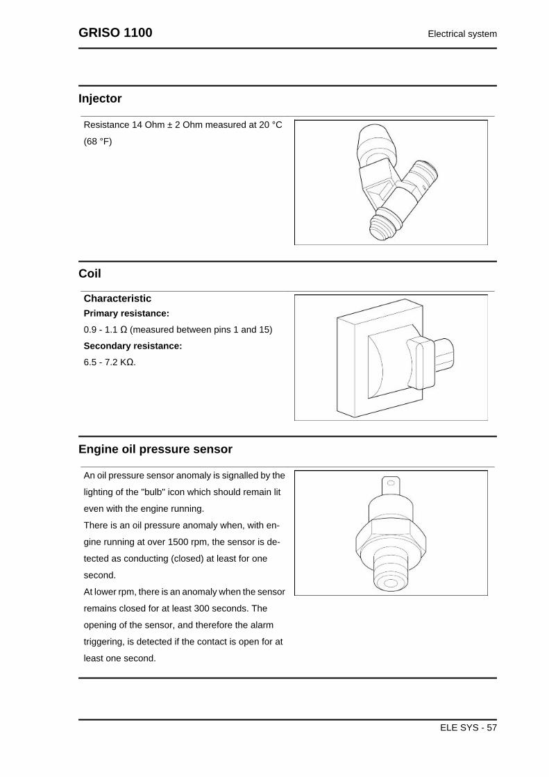
Injector
Resistance 14 Ohm ± 2 Ohm measured at 20 °C
(68 °F)
Coil
CharacteristicPrimary resistance:0.9 - 1.1 Ω (measured between pins 1 and 15)
Secondary resistance:6.5 - 7.2 KΩ.
Engine oil pressure sensor
An oil pressure sensor anomaly is signalled by the
lighting of the "bulb" icon which should remain lit
even with the engine running.
There is an oil pressure anomaly when, with en-
gine running at over 1500 rpm, the sensor is de-
tected as conducting (closed) at least for one
second.
At lower rpm, there is an anomaly when the sensor
remains closed for at least 300 seconds. The
opening of the sensor, and therefore the alarm
triggering, is detected if the contact is open for at
least one second.
GRISO 1100 Electrical system
ELE SYS - 57

Bank angle sensor
Normally open contact, 62 kOhm resistance, with
vehicle upright (straight sensor); Closed contact, 0
Ohm resistance, when the sensor is turned by 90°
with respect to its fitting position.
Air temperature sensor - instrument panel
CharacteristicResistance10 kOhm (at 25°C - 77°F)
Resistance32.5 kOhm (at 0°C - 32°F)
Connectors
Dashboard
The pin configuration of the grey-bodied connector is as follows:
PIN USE
1 + KEY
2 RIGHT TURN INDICATOR CONTROL
3 HIGH-BEAM LIGHT INPUT
4 -
5 -
6 K LINE
7 -
8 SELECT 1 - SET
9 FUEL LEVEL SENSOR
10 AIR TEMPERATURE SENSOR
11 + BATTERY
12 LEFT TURN INDICATOR CONTROL
Electrical system GRISO 1100
ELE SYS - 58

13 -
14 -
15 -
16 GENERAL EARTH CONNECTION
17 OIL PRESSURE SENSOR INTAKE
18 SENSORS EARTH CONNECTION
19 GENERAL GROUND (OPTIONAL)
20 GENERAL GROUND (OPTIONAL)
The pin configuration of the black-bodied connector is as follows:
PIN USE
21 + BATTERY
22 LEFT FRONT TURN INDICATOR ACTIVATION
23 LEFT REAR TURN INDICATOR ACTIVATION
24 AERIAL 1
25 -
26 CAN H
27 -
28 LIGHTS RELAY ACTIVATION
29 -
30 SELECT 2
31 + BATTERY
32 RIGHT FRONT TURN INDICATOR ACTIVATION
33 RIGHT REAR TURN INDICATOR ACTIVATION
34 AERIAL 2
35 -
36 CAN L
37 -
38 -
39 -
40 SELECT 3
GRISO 1100 Electrical system
ELE SYS - 59

Electrical system GRISO 1100
ELE SYS - 60

INDEX OF TOPICS
ENGINE FROM VEHICLE ENG VE

Vehicle preparation
Before removing the engine block, proceed as fol-
lows:
• Hold the vehicle steady with a stand
from the front and belts fixed to a hoist
from the rear.
• Place the engine service stand under
the oil sump.
• Remove the whole exhaust, the air fil-
ter housing, the fork together with the
cardan shaft, the fuel tank side fairings,
the spark plug covers and disconnect
the spark plug tubes.
• Empty the clutch control fluid through
the bleed pipe located under the sad-
dle.
Removing the engine from the vehicle
• Working on both sides disconnect the
injector connectors.
• Disconnect the throttle cables
Engine from vehicle GRISO 1100
ENG VE - 62

• Disconnect the idle motor connector.
• Disconnect the engine temperature
sensor connector
• Disconnect the throttle valve position
sensor connector
• Unscrew and remove the two screws
and collect the washer.
• Disconnect the revolution sensor con-
nector and collect the gasket.
GRISO 1100 Engine from vehicle
ENG VE - 63
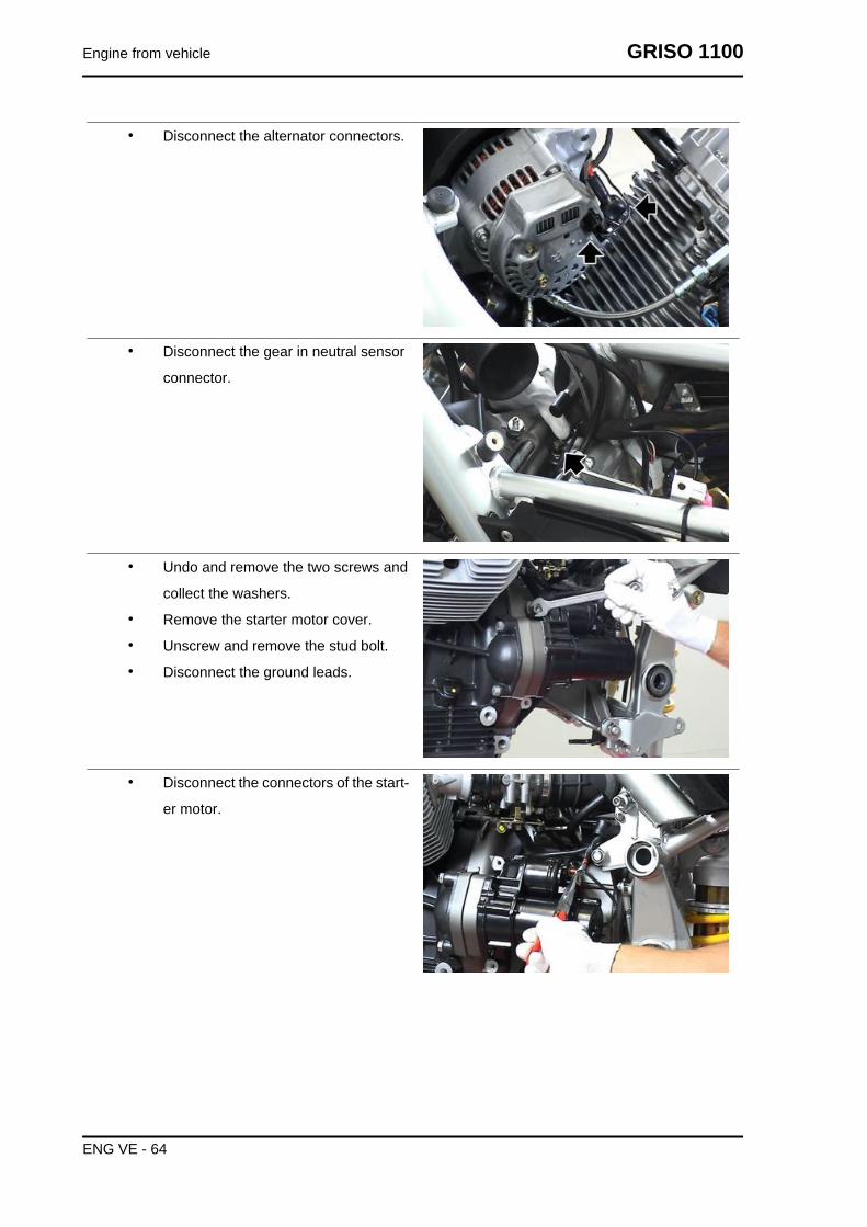
• Disconnect the alternator connectors.
• Disconnect the gear in neutral sensor
connector.
• Undo and remove the two screws and
collect the washers.
• Remove the starter motor cover.
• Unscrew and remove the stud bolt.
• Disconnect the ground leads.
• Disconnect the connectors of the start-
er motor.
Engine from vehicle GRISO 1100
ENG VE - 64

• Unscrew and remove the three screws
and remove the clutch control cylinder.
• Slide off the gearbox oil breather pipe.
• Working on both sides, release the
clamp and slide off the engine oil
breather pipe.
• Remove the oil vapour connecting
pipe.
• Unscrew and remove the two screws
fixing the oil vapour connecting pipe.
GRISO 1100 Engine from vehicle
ENG VE - 65
• Disconnect the stand sensor connec-
tor and release it from the clamps.
• Undo and remove the two screws and
remove the control unit protection.
• Undo and remove the two screws and
move the control unit downwards.
• Undo and remove the screws and
move the oil vapour recovery reservoir.
• Unscrew and remove the stud bolt.
• Unscrew and remove the engine lower
fixing nut and collect the washer.
• Remove the lower bolt and collect the
washer.
Engine from vehicle GRISO 1100
ENG VE - 66

• Working on both sides, unscrew and
remove the front screw and collect the
washer.
• Unscrew and remove the upper nut fix-
ing the engine and collect the washer.
• Remove the upper pin and collect the
washer.
• Unscrew and remove the nut and col-
lect the screw and the cable guide.
• Unscrew and remove the screw and
then remove the plate.CAUTIONPERFORM THE OPERATIONS BELOW AIDED BY A SEC-OND OPERATOR.
• Lower the engine partially.
• Disconnect the oil pressure sensor
connector.
• Fully lower the engine.
• Lift the rear part of the vehicle.
• Remove the front stand.
• Unhook the belts from the hoist holding
the rear part of the vehicle and remove
the chassis from the engine.
GRISO 1100 Engine from vehicle
ENG VE - 67

Installing the engine to the vehicle
• Secure the vehicle chassis with a hoist
and onto a front stand and lift the en-
gine to place it in position.
• Connect the oil pressure sensor con-
nector.
• Fit the plate and tighten the screw.
• Insert the screw, the cable guide and
screw the nut.
• Working from the right side, insert the
washer and the upper bolt.
• Fit the washer and insert the engine
upper fixing nut.
• Working on both sides, insert the
washer and screw the screw without
tighten it.
Engine from vehicle GRISO 1100
ENG VE - 68

• Working from the right side, fit the
washer and insert the lower bolt.
• Fit the washer and tighten the engine
lower fixing nut.
• Working on both sides, tighten the front screw to the prescribed torque.
• Tighten the stud bolt.
• Place the oil vapour recovery reservoir
and tighten the screw.
• Fit the control unit and tighten the two
screws.
• Fit the control unit cover and tighten the
two screws.
• Connect the stand sensor connector
and fix it to the chassis with new
clamps.
GRISO 1100 Engine from vehicle
ENG VE - 69

• Fit the oil vapour attachment pipe and
tighten the two fixing screws.
• Insert the oil breather pipe and fasten
it with a new clamp.
• Fit the gearbox oil breather pipe.
• Fit the clutch control cylinder.
• Tighten the three screws.
Engine from vehicle GRISO 1100
ENG VE - 70

• Fit the clutch bleed pipe on the cable
guide.
• Fill up the clutch system.
• Connect the starter motor connectors.
• Connect the ground cables and tighten
the screw.
• Fit the starter motor cover.
• Place the two washers and tighten the
two screws.
• Connect the neutral sensor connector.
GRISO 1100 Engine from vehicle
ENG VE - 71
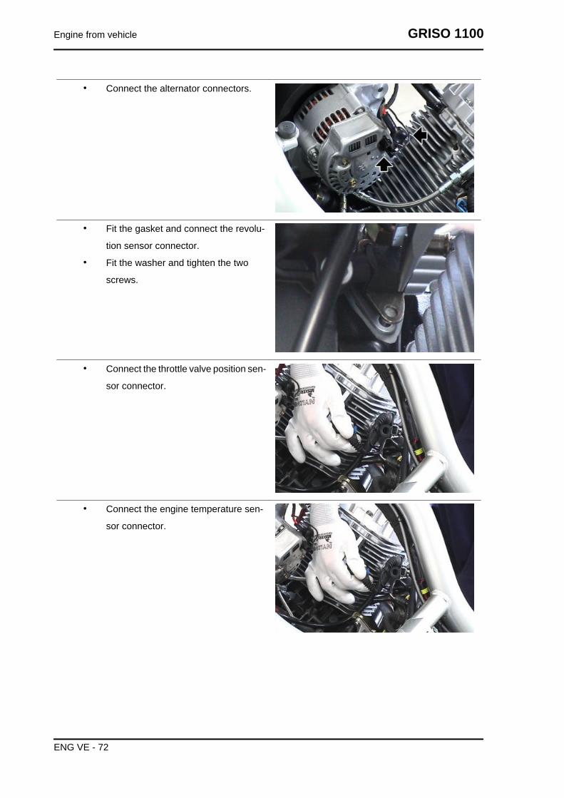
• Connect the alternator connectors.
• Fit the gasket and connect the revolu-
tion sensor connector.
• Fit the washer and tighten the two
screws.
• Connect the throttle valve position sen-
sor connector.
• Connect the engine temperature sen-
sor connector.
Engine from vehicle GRISO 1100
ENG VE - 72

• Connect the idle motor connector.
• Connect and adjust the throttle grip ca-
ble clearance.
• Working on both sides, connect the in-
jector connectors.
• Working on both sides, connect the
spark plug tubes.
• Working from both sides, fit the insert
and tighten the two internal screws.
• Working from both sides, fit the spark
plug cover and tighten the two external
screws.
• Install the fuel tank.
• Fit the saddle.
• Working from both sides, fit the fairing
and tighten the three screws.
• Fit the fork together with the cardan
shaft.
• Install the whole exhaust, the air filter
housing, the fuel tank and the saddle.
GRISO 1100 Engine from vehicle
ENG VE - 73

INDEX OF TOPICS
ENGINE ENG

Gearbox
Diagram
KEY:
1. Ball bearing
2. Circlip
GRISO 1100 Engine
ENG - 75

3. Shim washer
4. Pin
5. Desmodromic compl.
6. Ball bearing
7. Spring
8. Spacer
9. Circlip
10. Fifth wheel
11. Linking pin
12. Gear
13. Circlip
14. Shoulder washer
15. Ball bearing cage
16. Gear
17. Sealing ring
18. Ball bearing
19. Gear
20. Circlip
21. Washer
22. Half ring
23. Oil cap
24. Washer
25. Gearbox
26. Aluminium gasket
27. Bleed cap
28. Neutral sensor
29. Gasket
30. Sealing ring
31. Bushing
32. Gasket
33. Oil drainage cap
34. Roller bearing
35. Circlip
36. Belleville spring
37. Pressure plate
38. Shaped washers
39. Sleeve
40. Circlip
Engine GRISO 1100
ENG - 76
41. Transmission gear
42. Ball bearing
43. Gear
44. Gear
45. Ball bearing cage
46. Shoulder washer
47. Circlip
48. Gear
49. Circlip
50. Gear
51. Main shaft
52. Transmission gear
53. Ring nut
54. Washer
55. Clutch internal body
56. Sealing ring
57. Ball bearing
58. O-Ring
59. Clutch shaft
60. Fork
61. Fork shaft
62. Fork
63. Fork
64. Gear
65. Gear
66. Ball bearing
67. Secondary shaft
68. Gear
69. Spacer
70. Spring
71. Index lever
72. Bushing
73. Pre-selector compl.
74. Spring
Gearbox
GRISO 1100 Engine
ENG - 77

Removing the gearbox
• Remove the starter motor.
• Make sure the transmission is in idle.
• Undo and remove the screw and re-
move the gearbox lever.
• Unscrew and remove the cap.
• Place a container of suitable capacity
under it, unscrew and remove the cap
and then bleed all gearbox oil.
• Unscrew and remove the three screws.
Engine GRISO 1100
ENG - 78

• Unscrew and remove the two screws.
• Unscrew and remove the screw.
• Remove the gearbox.
See alsoRemoving thestarter motorReplacement
Gearbox shafts
GRISO 1100 Engine
ENG - 79

Disassembling the gearbox
• Remove the gearbox.
• Place the gearbox on the specific gearbox support tool and on a vice.
Specific tooling05.90.25.30 Gearbox support
• Unscrew and slide off the odometer
gear and collect the abutment washer
that is inside the gearbox.
• From the outside, slide off the thrust
cylinder and collect the O-Ring and the
washer.
• Remove the thrust bearing and the
washer.
Engine GRISO 1100
ENG - 80

• Slide off the two bushings (1) and re-
move the rod (2), collect the bushing
(3).
• Fold the washer fins.
• Using the adequate ring nut spanner and the clutch body locking tool, unscrew and remove
the ring nut, and collect the clutch internal body.
Specific toolingGU14912603 Hook spanner for fixing ring nut of the clutch shaft internal body
30.91.28.10 Clutch body locking
• Open the gearbox using the specific
tool.
Specific tooling05.91.25.30 Gearbox opening
GRISO 1100 Engine
ENG - 81

• Release the spring.
• Pressing the selector, slide off the
whole transmission lever.
• Unscrew and remove the threaded ref-
erence pin.
• Use rubber bands to tie down the trans-
mission shaft unit and extract it.
Engine GRISO 1100
ENG - 82

• Remove the bearings from the gearbox
if necessary.
• Once the transmission shaft unit is in
on a bench, remove the rubber bands,
being careful with the group.
• Detach the shafts and label the forks
before removal.
• Remove the forks and collect the shaft.
GRISO 1100 Engine
ENG - 83

• Replace bearings if necessary and re-
move the clutch shaft.
Removing the primary shaft
• Remove the main shaft.
• Operate on the main shaft from the
second gear side.
Engine GRISO 1100
ENG - 84

• Remove the gear of the second gear
and collect the ball bearing cage.
• Remove the gear of the sixth gear and
collect the shoulder washer.
• Remove the circlip.
• Remove the gear of the third and fourth
gears.
GRISO 1100 Engine
ENG - 85

• Remove the circlip and collect the
shoulder washer.
• Remove the gear of the fifth gear and
collect the ball bearing cage.
• Heat the shaft with a specific heater
and remove the helical transmission
gear.
Removing the secondary shaft
• Remove the transmission shaft.
• Operate on the shaft from the grooved
side.
Engine GRISO 1100
ENG - 86

• Remove the shoulder washer.
• Remove the gear of the second gear
and collect the ball bearing cage and
the shoulder washer.
• Remove the circlip.
• Remove the gear of the sixth gear.
GRISO 1100 Engine
ENG - 87

• Remove the circlip and collect the
shoulder washer.
• Remove the gear of the fourth gear and
collect the ball bearing cage.
• Remove the gear of the third gear and
collect the ball bearing cage and the
shoulder washer.
• Remove the circlip.
Engine GRISO 1100
ENG - 88

• Remove the gear of the fifth gear.
• Remove the circlip, the shoulder wash-
er and remove the gear of the first gear,
collect the ball bearing cage.
• Remove the bearing if necessary.
See alsoDisassembling the gearbox
Disassembling the clutch shaft
• Remove the gearbox from the engine
block.
• Remove the gearbox.
• Insert the clutch shaft in the special tool
for removal.
Specific tooling000019663300 Tool for clutch shaft removal
• Compress the Belleville springs (10) until releasing the two half-rings (12).
• Remove the Belleville springs (10).
• Remove the washer (11).
• Remove the shaped washers (8).
• Remove the sleeve (7).
• Remove the circlip (6).
• Remove the transmission gear (5).
• Collect the clutch shaft (4).CAUTION
GRISO 1100 Engine
ENG - 89

VEHICLES WITH CHASSIS NUMBER FROM ZGULS00096M112690 TO ZGULS00096M113440MAY PRESENT SOME NOISE PROBLEMS AT IDLE SPEED.TO REDUCE THIS NOISE, ON THE CLUTCH SHAFT, FIT TWO SHAPED WASHERS (8) BESIDESTHE ONE ALREADY PRESENT IN THE ASSEMBLY
Checking the primary shaft
Measure coaxiality of the main shaft with a dial
gauge and a centring device and replace it if not
complying with specifications.
CharacteristicShaft coaxiality limit0.08 mm (0.0031 in)
Check transmission gears for signs of pitting and wear and replace damaged gears if necessary.
Check the gear fitting teeth for cracks, damage and wear and replace those damaged if necessary.
Check the transmission gears movement and, if it is not regular, replace the damaged part.
Engine GRISO 1100
ENG - 90

Checking the secondary shaft
Measure the coaxiality of the transmission shaft
with a dial gauge and a centring device and re-
place it if not complying with specifications.
CharacteristicShaft coaxiality limit0.08 mm (0.0031 in)
Check transmission gears for signs of pitting and wear and replace damaged gears if necessary.
Check the gear fitting teeth for cracks, damage and wear and replace those damaged if necessary.
Check the transmission gears movement and, if it is not regular, replace the damaged part.
Checking the desmodromic drum
Check gear drum for damage, scratches and wear
and replace the desmodromic control rod if nec-
essary.
Check the desmodromic segment «3» for damage
and wear and replace it if necessary.
Check the desmodromic bearing «4» for damage
and cracks and replace it if necessary.
Checking the forksNOTE
THE FOLLOWING PROCEDURE IS VALID FOR ALL GEARBOX FORKS.• Check the transmission fork cam roller
«1» and the transmission fork tooth
«2» for damage, deformation and
wear.
• Replace the transmission fork if nec-
essary.
GRISO 1100 Engine
ENG - 91

• Check the transmission fork move-
ment and if it is not regular, replace the
transmission forks.
See alsoDisassembling the gearbox
Fitting the primary shaftNOTE
TO REFIT, FOLLOW THE SAME INSTRUCTIONS AS FOR REMOVAL BUT IN REVERSE ORDER.REMEMBER TO REPLACE ALL SEALING RINGS, CIRCLIPS AND SAFETY RINGS PREVIOUSLYREMOVED.
See alsoRemoving theprimary shaft
Fitting the secondary shaftNOTE
TO REFIT, FOLLOW THE SAME INSTRUCTIONS AS FOR REMOVAL BUT IN REVERSE ORDER.REMEMBER TO REPLACE ALL SEALING RINGS, CIRCLIPS AND SAFETY RINGS PREVIOUSLYREMOVED.
See alsoRemoving thesecondary shaft
Assembling the clutch shaftNOTE
TO REFIT, FOLLOW THE SAME INSTRUCTIONS AS FOR REMOVAL BUT IN REVERSE ORDER.REMEMBER TO REPLACE ALL SEALING RINGS, CIRCLIPS AND SAFETY RINGS PREVIOUSLYREMOVED.
Assembling the gearboxNOTE
TO REFIT, FOLLOW THE SAME INSTRUCTIONS AS FOR REMOVAL BUT IN REVERSE ORDER.REMEMBER TO REPLACE ALL SEALING RINGS, CIRCLIPS AND SAFETY RINGS PREVIOUSLYREMOVED.
See alsoDisassembling the gearbox
Engine GRISO 1100
ENG - 92

Flywheel
Removing the flywheel
• Remove the clutch.
• Position the locking tool on the flywheel
and loosen the six flywheel fixing
screws operating diagonally and in
stages.
• Remove the locking tool.
Specific tooling12.91.18.01 Tool to lock the flywheel and thestarting ring gear
• Remove the flywheel.
See alsoDisassembling theclutch
Checking
• Check that the flywheel surface that contacts the plate is not scratched.
• Check that the contact faces on the crankshaft are not distorted; if they are, replace the
flywheel.
GRISO 1100 Engine
ENG - 93

Installing the flywheel
• Position the flywheel.NOTERESPECT THE FLYWHEEL POSITIONING REFERENCES.CAUTIONTHE SCREWS MUST BE REPLACED WITH NEW ONES ATTHE FOLLOWING REFITTING AS THEY ARE SUBJECT TOHIGH LOADS AND STRESS.
• Position the locking tool on the flywheel
and tighten the six flywheel sealing
screws operating diagonally and in
stages.
• Fit the clutch.
Specific tooling12.91.18.01 Tool to lock the flywheel and thestarting ring gear
See alsoAssembling theclutch
Generator
Removing the generator
• Unscrew and remove the six screws
and collect the bushings.
Engine GRISO 1100
ENG - 94

• Remove the cover.
• Unscrew and remove the eight screws.
• Undo and remove the two screws.
• Unscrew the nut and collect the screw.
GRISO 1100 Engine
ENG - 95

• Loosen the screw.
• Loosen the nut and undo the set screw
so that the alternator slides down.
• Completely loosen and remove the
screw.
• Remove the belt and the alternator with
pulley.
Engine GRISO 1100
ENG - 96
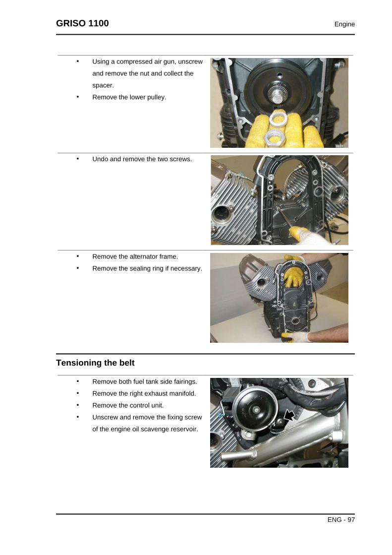
• Using a compressed air gun, unscrew
and remove the nut and collect the
spacer.
• Remove the lower pulley.
• Undo and remove the two screws.
• Remove the alternator frame.
• Remove the sealing ring if necessary.
Tensioning the belt
• Remove both fuel tank side fairings.
• Remove the right exhaust manifold.
• Remove the control unit.
• Unscrew and remove the fixing screw
of the engine oil scavenge reservoir.
GRISO 1100 Engine
ENG - 97

• Unscrew and remove the spacer.
• Unscrew and remove the five fixing
screws of the timing system cover.
• Remove the timing system cover.
• Loosen the set screw lock nut.
• Using the belt tensioning tool (code
06.94.86.00), tension the belt to the
prescribed torque.
• Screw the set screw.
• Tighten the lock nut.
Specific tooling06.94.86.00 belt tensioning tool
Installing the generator
• If the sealing ring has been previously
removed, replace it using the punch of
the timing system cover sealing ring.
Specific tooling05.92.72.30 Timing system cover sealing ringpunch
Engine GRISO 1100
ENG - 98

• Replace the gasket and place the al-
ternator frame using the front cover in-
sertion cone.
• Remove the insertion cone afterwards.
Specific tooling05.91.17.30 Front cover insertion cone
• Tighten the two screws.
• Tighten the eight lower screws.
• Operating diagonally and in stages,
tighten the ten fixing screws on the al-
ternator fitting.
• Position the lower pulley and the
spacer.
• Tighten the nut to the prescribed tor-
que.
GRISO 1100 Engine
ENG - 99

• Position the alternator and the timing
system belt.
• Position the screw and pre-tighten it.
• Position the screw and tighten the nut.
• Using the belt tensioning tool (code
06.94.86.00), tension the belt to the
prescribed torque and screw the set
screw.
• Remove the belt tensioning tool.
• Lock the set screw in position by
screwing the lock nut.
Specific tooling06.94.86.00 belt tensioning tool
Engine GRISO 1100
ENG - 100

• Tighten the alternator fixing screws.
• Tighten the four screws, operating di-
agonally and in stages.
• Position the timing system cover.
• Tighten the five screws, operating in
oblique direction and in stages.
Starter motor
Removing the starter motor
• Undo and remove the two screws and
collect the washers.
GRISO 1100 Engine
ENG - 101

• Slide off the starter motor.
Clutch side
Disassembling the clutch
• Remove the gearbox from the engine.
• Use the locking tool and the clutch
spring compression tool on the fly-
wheel.
Specific tooling30.90.65.10 Tool for clutch fitting
12.91.18.01 Tool to lock the flywheel and thestarting ring gear
• Undo and remove the eight sealing
screws from the sprocket gear on the
engine flywheel.
• Remove the start-up sprocket gear.
Engine GRISO 1100
ENG - 102

Extract from the inside of the engine flywheel:
• the clutch plate.
• The intermediate plate.
• The second clutch plate.
• The pressure plate disc cover.
GRISO 1100 Engine
ENG - 103

• The pressure plate disc with springs.
Checking the clutch plates
Driven plates
Check that the supporting surfaces with the driven plates are perfectly smooth and even and that the
external toothing that works inside the flywheel is not damaged, otherwise, replace the plate.
Crown gear for start-up
Check that the supporting surface with the driven plate is perfectly smooth and even.
Also check that the toothing where the starter motor pinion works is not chipped or scratched; otherwise,
replace it.
Checking the clutch housing
Check that the teeth do not show any marks on the plate faying areas and that the toothing inside the
clutch bell is in good conditions.
Checking the pusher plate
Pressure plate
Check that the plate does not show signs of wear on the opening where the control cap works, and that
the supporting surfaces with the driven plate are perfectly even.
Checking the springs
Check that the springs are still flexible and are not
deformed:
• Springs compressed at 22 mm (0.8661
in) must bear a load of 11.25 ÷ 11.70
kg (24.80 ÷ 25.79 pounds);
• Springs compressed at 20 mm (0.7874
in) must bear a load of 14.75 ÷ 15.30
kg (32.52 ÷ 33.73 pounds).
Engine GRISO 1100
ENG - 104

Assembling the clutch
Insert the components in the clutch bell in the fol-
lowing order:
• the pressure plate with springs.
• Make sure that the reference marked
on the pressure plate tooth is aligned
with the reference on the flywheel.
• Use the locking tool and the clutch
spring compression tool on the fly-
wheel.
Specific tooling30.90.65.10 Tool for clutch fitting
12.91.18.01 Tool to lock the flywheel and thestarting ring gear
GRISO 1100 Engine
ENG - 105

• Remove the locking tool.
• Fit the clutch disc.
Specific tooling12.91.18.01 Tool to lock the flywheel and thestarting ring gear
• The intermediate disc.
• The clutch disc.
• Place the crown gear aligning its refer-
ence with that on the flywheel.
Engine GRISO 1100
ENG - 106

• Tighten the eight screws sealing the
crown gear to the flywheel to the pre-
scribed torque
• Remove the special tool for clutch
spring compression.
Specific tooling30.90.65.10 Tool for clutch fitting
• Insert the pressure plate disc cover.
• Install the gearbox unit.
Head and timing
Removing the head coverNOTE
THE FOLLOWING OPERATIONS REFER TO REMOVING ONLY ONE COVER BUT APPLY TOBOTH COVERS.
• Unscrew and remove the eight screws
and collect the bushings.
GRISO 1100 Engine
ENG - 107

• Remove the head cover and collect the
gasket.
Removing the cylinder head
• Remove the rocker rods.
• Unscrew and remove the outer spark
plug.
• Loosen the nut and disconnect the
pipes that deliver oil to the head.
• Unscrew and remove the threaded
cap.
Engine GRISO 1100
ENG - 108
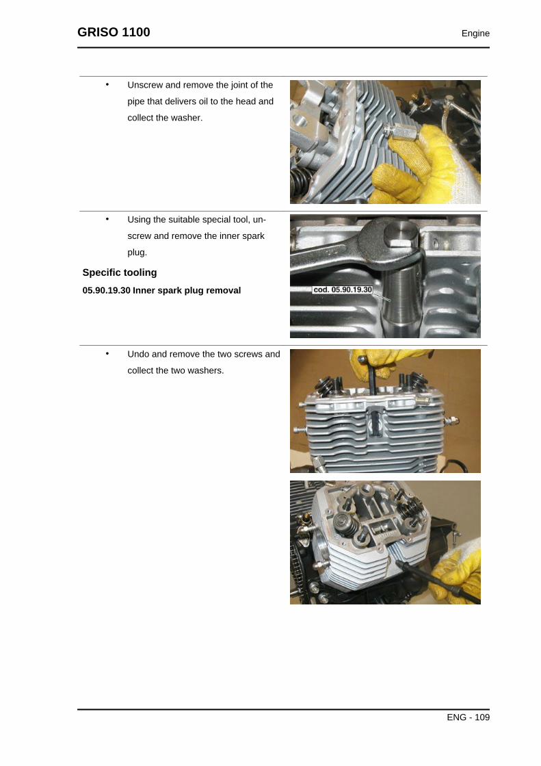
• Unscrew and remove the joint of the
pipe that delivers oil to the head and
collect the washer.
• Using the suitable special tool, un-
screw and remove the inner spark
plug.
Specific tooling05.90.19.30 Inner spark plug removal
• Undo and remove the two screws and
collect the two washers.
GRISO 1100 Engine
ENG - 109

• Slightly detach the cylinder head and
remove the four O-rings.
• Remove the head and collect the gas-
ket.
Cylinder head
Removing the rocker armsNOTE
THE FOLLOWING OPERATIONS REFER TO REMOVING ONLY ONE HEAD BUT APPLY TO BOTHHEADS.
• Remove the head cover.
• Rotate the crankshaft to TDC position in com-
bustion phase (closed valves) for the left cylinder.
• Unscrew and remove the two screws.
Engine GRISO 1100
ENG - 110

• Remove the rocking lever shafts.
• Remove the rocking levers and collect the three
washers.
See alsoRemoving thehead cover
Removing the valves
• Remove the head.
• Place the special tool on the upper cap
and at the centre of the head of the
valve to be removed.
Specific tooling10.90.72.00 Tool for valve removal and refitting
• Tighten the tool screw until fitted, and
then hit the tool head (where the upper
retainer works) with a mallet so that the
two cotters (1) get detached from the
upper retainer (2).
• Once the two cotters (1) are detached,
screw these cotters until they can be
GRISO 1100 Engine
ENG - 111

slid off the valve seats; unscrew the
tool and remove it from the head.
• Remove the upper retainer (2).
• Remove the internal spring (3).
• Remove the external spring (4).
• Remove the lower retainer (5) and the
shimming washers if necessary.
• Remove the valve (6) from inside the
head.
Checking the valve guides
Use a punch to extract the valve guides from the
heads.
The valve guides should be replaced only if the
clearance between them and the stem cannot be
eliminated by simply replacing the valves.
To refit the valve guides on the head, follow this
procedure:
• Heat the head in an oven at approxi-
mately 60°C (140°F).
• Lubricate the valve guide.
• Fit the circlips.
• Press a punch with the valve guides.
• Use a reamer to bore the holes the
valve stems slide through so that the
inside diameter is at the prescribed val-
ue. The interference between the seat
on the head and the valve guide must
be 0.046 - 0.075 mm (0.0018 - 0.0030
in)
VALVE AND GUIDES COUPLING DATACHART (INLET)
Specification Desc./QuantityValve guide inside diameter
mm (in)8.000 ÷ 8.022 (0.3150 ÷
0.3158)Valve stem diameter 7.972 ÷ 7.987 (0.3139 ÷
0.3145)Fitting clearance mm (in) 0.013 ÷ 0.050 (0.0005 ÷
0.0020)
Engine GRISO 1100
ENG - 112

VALVE AND GUIDES COUPLING DATACHART (OUTLET)
Specification Desc./QuantityValve guide inside diameter
mm (in)8.005 ÷ 8.022 (0.3152 ÷
0.3158)Valve stem diameter mm (in) 7.965 ÷ 7.980 (0.3136 ÷
0.3142)Fitting clearance mm (in) 0.025 ÷ 0.057 (0.0010 ÷
0.0022)
Checking the cylinder head
Check that:
• The planes of contact with the cover and with the cylinder are not scored or damaged so as
to compromise a perfect seal.
• Check that the clearance between the valve guide holes and valve stanchions is within the
prescribed limits.
• Check the status of the valve seats.
The valve seats should be reamed with a mill. The
seat inclination angle is 45° +/- 5'. After milling, it
is necessary to grind them to ensure a good cou-
pling and a perfect sealing between the ring nuts
and the valve heads.
Installing the valvesNOTE
THE FOLLOWING OPERATIONS REFER TO REMOVING ONLY ONE HEAD BUT APPLY TO BOTHHEADS.
GRISO 1100 Engine
ENG - 113

• Place the valve (6) inside the head.
• Place the lower retainer (5) and the
shimming washers.
• Place the external spring (4).
• Place the internal spring (3).
• Insert the upper retainer (2).
• Place the two cotters (1) on the seats
on the valves.
• Compressing the spring with the spe-
cial valve tool, install the valve cotters.
Specific tooling10.90.72.00 Tool for valve removal and refittingNOTEUPON REFITTING, PLACE THE O-RING CORRECTLY ONTHE VALVE.
• Remove the special tool
Engine GRISO 1100
ENG - 114

Installing the rocker armsCAUTIONUPON REFITTING, ALWAYS REPLACE THE O-RINGS
CAUTIONUPON REFITTING, DO NOT INVERT THE POSITION OFTHE ROCKING LEVER SUPPORTS SO AS NOT TO COM-PROMISE LUBRICATION.CAUTIONTHE NEW LUBRICATION SYSTEM IS VALID FROM EN-GINE NUMBER KS13770 ON.
• Install the rocking lever rods if they
have been previously removed.
• Install the rocking lever support and re-
place the four O-rings.
• Place the four washers and screw the
four nuts.
GRISO 1100 Engine
ENG - 115

• Place the six washers and install the
rocking levers.
• Insert the rocking lever shafts.
• Rotate the crankshaft to TDC position
in combustion phase (closed valves)
for the left cylinder.
• Tighten the two screws.
See alsoInstalling the rods
Timing
Engine GRISO 1100
ENG - 116

Chain removal
• Remove the engine assembly.
• Remove the alternator.
• Clearly indicate the distribution timing
marks that should be restored at the
next refitting (left cylinder TDC).
• Using the adequate tool, lock the igni-
tion crown.
Specific tooling12.91.18.01 Tool to lock the flywheel and thestarting ring gear
• Unscrew the central sealing nut of the
camshaft gear and collect the washer.
• Remove the cotter.
GRISO 1100 Engine
ENG - 117
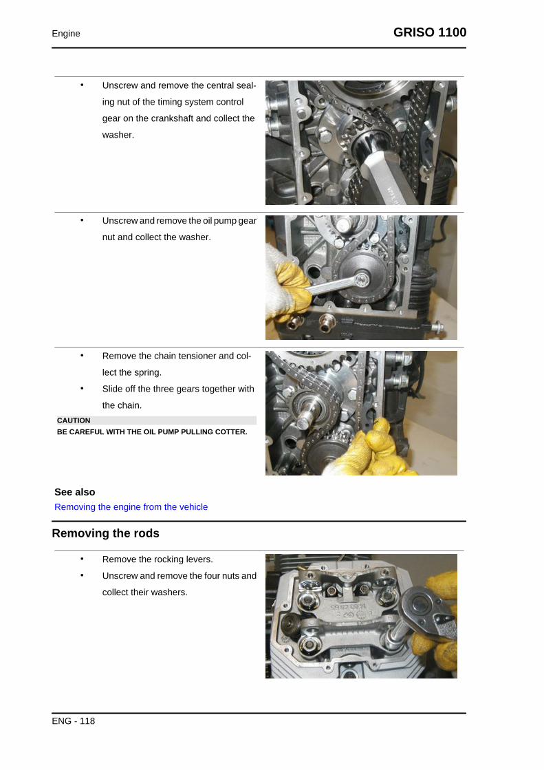
• Unscrew and remove the central seal-
ing nut of the timing system control
gear on the crankshaft and collect the
washer.
• Unscrew and remove the oil pump gear
nut and collect the washer.
• Remove the chain tensioner and col-
lect the spring.
• Slide off the three gears together with
the chain.CAUTIONBE CAREFUL WITH THE OIL PUMP PULLING COTTER.
See alsoRemoving the engine from the vehicle
Removing the rods
• Remove the rocking levers.
• Unscrew and remove the four nuts and
collect their washers.
Engine GRISO 1100
ENG - 118

• Remove the rocking lever support.
• Remove the two rocking lever rods
See alsoRemoving the rocker arms
Removing the tappets
• Remove the engine assembly.
• Remove both heads.
• Slide off and remove the tappets from
their seat on both sides.
See alsoRemoving the engine from the vehicle
GRISO 1100 Engine
ENG - 119

Removing the phonic wheel
• Remove the timing chain.
• Slide off the tone wheel and collect the
plug.
See also
Chain removal
Removing the camshaft
• Remove the timing chain.
• Remove the tone wheel.
• Remove the tappets.
• Remove the rods.
• Unscrew and remove the three screws
and collect the washers.
• Remove the flange.
Engine GRISO 1100
ENG - 120

• Remove the camshaft.
Installing the camshaftNOTE
FOR TIMING SYSTEM REFITTING, IT IS NECESSARY TO HEAT THE ENGINE WITH A SUITABLEHEATER IN ORDER TO INSERT THE CAMSHAFT CORRECTLY AND WITHOUT DAMAGING IT.
Follow the camshaft removal instructions but in reverse order.
Installing the rods
• Install the head if it has been previously
removed.
• Replace the four O-rings.
• Install the two rocking lever rods.
Installing the chain
For the installation of the three gears and of the timing chain carry out the operations indicated in section
"Timing".
GRISO 1100 Engine
ENG - 121

Cam timing
• On the crankcase, fit the crankshaft
and the camshaft.
• Fit the cylinders and the heads.
• Fit the rods.
• Do not fit the rocking levers before car-
rying out engine timing so as not to
damage the valves during the rotation
of the camshaft.
• Turn the crankshaft until the left cylin-
der piston reaches the top dead centre
(TDC).
• Fit the flywheel on the crankshaft align-
ing the stamp arrow on the flywheel
with the fixed reference on the crank-
case.
• Position the locking tool on the flywheel
and tighten the six flywheel sealing
screws operating diagonally and in
stages.
• Fit the clutch.
Specific tooling12.91.18.01 Tool to lock the flywheel and thestarting ring gear
• Fit the plug on the camshaft.
• Introduce the tone wheel with the
smooth side facing outward.
Engine GRISO 1100
ENG - 122

• Place the shim washer adequately so
that the timing chain do not wear out
the crankcase.
• Fit the three timing system gears and
the chain aligning the references on
the camshaft and crankshaft gears.
• Introduce the belleville spring and the
nut to fasten the camshaft gear.
• Introduce the washer and the nut to
fasten the crankshaft gear.
GRISO 1100 Engine
ENG - 123

• Turn the oil pump shaft and introduce
the gear pulling woodruff key.
• Introduce the chain tensioner.
• Remove the flywheel locking tool.
• Check the crankshaft rotation.
• Fit the rocking levers.
Specific tooling12.91.18.01 Tool to lock the flywheel and the starting ring gear
Timing
To check distribution timing, follow these instruc-
tions:
• Obtain a clearance between rocking
levers and valves equal to 1.5 mm
(0.059 in);
• Place the hub for graduated dial and
the relative graduated dial on the
crankshaft slot, inserting the spacer
and fixing it to the shaft with the nut.
Specific tooling981006 Graduated dial hub
19.92.96.00 Graduated dial to control ignitiontiming
Engine GRISO 1100
ENG - 124

• With a screw, fasten the specific arrow
to the threaded hole to the left of the
crankcase.
Specific tooling17.94.75.60 Arrow to control ignition timing
• Fit the dial gauge support and then the
gauge itself on the left outer spark plug
hole.
• Rotate the crankshaft until the left cyl-
inder piston is actually at the top dead
centre (with valves closed).
• Reset the dial gauge and make sure
the references (on the timing system
gears and the engine pinion) are per-
fectly aligned, so that looking through
the checking hole on the gearbox, the
reference line marked 'S' is perfectly
aligned with the reference marked at
the centre of the hole.
• Align the arrow point with the TDC zero
on the graduated dial.
GRISO 1100 Engine
ENG - 125

• Observing the timing system diagram,
check timing considering that:
A - intake start opens 22° before TDC
B - exhaust end closes 24° after TDC
C - exhaust start opens 52° before BDC
D - intake end closes 54° after BDC
• Screw the dial gauge support and then
the gauge itself on the right cylinder
outer spark plug hole.
• With a screw, fix the arrow to the threa-
ded hole to the right of the crankcase.
• Turn the disc clockwise until the refer-
ence marked with letter 'D' is aligned
with the reference at the centre of the
checking hole on the gearbox (valves
closed).
• Repeat the operations described
above for the left cylinder.
• After the check and if everything is correct, operate as follows to restore the operation clear-
ance between rocking levers and valves (intake 0.10 mm (0.0039 in), outlet 0.15 mm (0.0059
in).
• Remove the graduated dial hub, the graduated dial, the arrow, the dial gauge support and
the gauge itself.
Engine GRISO 1100
ENG - 126

• Refit the spark plugs and finish the refit.
Specific tooling981006 Graduated dial hub
19.92.96.00 Graduated dial to control ignition timing
17.94.75.60 Arrow to control ignition timing
Measuring air gap
• Undo and remove the two screws and
remove the sensor.
• Insert a suitable plain washer on the
sensor and note its thickness.
GRISO 1100 Engine
ENG - 127

• Place the sensor on the timing system
cover and cause it to make contact with
the tone wheel.
• Measure the clearance between the
fixing plate and the cover with a feeler
gauge. Subtract the plain washer value
from this measurement to obtain the
clearance between the sensor and the
tone wheel.
• Remove the washer and fit the sensor after applying adequate sealing paste on the fixing
plate, then tighten the screws to the prescribed torque.
Cylinder-piston assembly
Removing the cylinderNOTE
THE OPERATIONS DESCRIBED BELOW REFER TO ONE HEAD REMOVING ONLY BUT APPLYTO BOTH HEADS.
• Remove the head.
• Slide off the gasket.
Engine GRISO 1100
ENG - 128

• Slide off the cylinder from the stud
bolts, paying attention not to damage
the piston.
See alsoRemoving thecylinder head
Disassembling the pistonNOTE
THE OPERATIONS DESCRIBED BELOW REFER TO ONE HEAD REMOVING ONLY BUT APPLYTO BOTH HEADS.
• Remove the cylinder.
• Cover the crankcase opening with a
clean cloth.
• Release the snap ring.
• Remove the pin.
GRISO 1100 Engine
ENG - 129

• Mark the piston crown on the exhaust
side so as to remember the refitting po-
sition.
• Remove the piston.
Fitting the pistonNOTE
THE OPERATIONS DESCRIBED BELOW REFER TO REMOVING ONLY ONE HEAD BUT APPLYTO BOTH HEADS.
• Fit the piston.NOTECHECK THE ORIENTATION OF THE PISTON ACCORDINGTO THE REFERENCES AT THE TOP. DO NOT ASSEMBLEPISTONS AND CYLINDERS OF DIFFERENT SELECTORTYPES.
• Insert the pin.
• Insert the pin clip.
Engine GRISO 1100
ENG - 130

Installing the cylinder
• Fit the piston.
• Remove the cloth used to prevent foreign bodies coming into the crankcase.
• Turn the rings so that the junction ends are 120 degrees from each other.
• Lubricate piston and cylinder.
• Using a specific tool for piston ring clamps, place the cylinder.CAUTION
DURING THIS OPERATION, PAY ATTENTION NOT TO DAMAGE THE PISTON.
Specific tooling05.92.80.30 Piston ring clamp
• Remove the piston ring clamp tool and
finish positioning the cylinder.
Specific tooling05.92.80.30 Piston ring clamp
CAUTIONUPON REFITTING DO NOT INVERT THE POSITION OF THECYLINDER GASKET SO AS NOT TO COMPROMISE LU-BRICATION.CAUTIONTHE NEW LUBRICATION SYSTEM IS VALID FROM EN-GINE NUMBER KS13770 ON.
• Place the gasket on the cylinder base.
• Fit the head.
See alsoFitting the piston
GRISO 1100 Engine
ENG - 131

Installing thecylinder head
Installing the cylinder head
• Fit the valves if they have been previ-
ously removed.
• Replace the gasket between head and
cylinder.
• Fit the head.
• Place the two washers and tighten the
two screws.
• Using the suitable special tool, screw
the inner spark plug.
Specific tooling05.90.19.30 Inner spark plug removal
Engine GRISO 1100
ENG - 132

• Insert the washer and screw the joint of
the pipe that delivers oil to the head .
• Screw the threaded cap.
• Connect the pipes that deliver oil to the
head and screw the nut.
• Install the outer spark plug.
GRISO 1100 Engine
ENG - 133

• Replace the gasket and install the
head cover.
See alsoInstalling thehead cover
Installing the head cover
• Replace the gasket and fit the head
cover.
• Place the bushings and cross tighten
the eight screws.
Crankcase - crankshaft
Removing the crankshaft
• Remove the connecting rods.
Engine GRISO 1100
ENG - 134

• Undo and remove the eight fixing
screws and collect the washers.
• Hold the crankshaft during flange re-
moval.
• Using the suitable special tool, remove
the crankshaft flange.
• Remove the sealing ring from the
flange, if necessary.
Specific tooling12.91.36.00 Tool to remove the flywheel-sideflange
• Remove the crankshaft afterwards.
See alsoDisassembling the connecting rod
Disassembling the connecting rod
• Remove the heads.
• Remove the cylinders and the pistons.
• Remove the clutch.
• Remove the flywheel.
• Remove the timing system.
• Remove the oil sump.
GRISO 1100 Engine
ENG - 135

• Loosen the coupling screws 'A' from
inside the crankcase and remove the
connecting rods 'B'.
See alsoRemoving the flywheelDisassembling the pistonRemoving thecylinderRemoving thecylinder head
Inspecting the crankshaft components
Check the surfaces of the main journals; if they are scored or oval-shaped, reface them (observing the
undersize charts), and replace the flanges and the main journals.
FITTING CLEARANCESSpecification Desc./Quantity
Between the bearing and the main journal on the timing systemside
0.028 ÷ 0.060 mm (0.00110 ÷ 0.00236 in);
Between the bearing and the main journal on the flywheel side 0.040 ÷ 0.075 mm (0.00157 ÷ 0.00295 in)Between the bearing and the connecting rod pin 0.022 ÷ 0.064 mm (0.00087 ÷ 0.00252 in)
MAIN JOURNAL DIAMETER ON THE TIMING SYSTEM SIDE (A)Specification Desc./Quantity
Main journal regular production 37.975 mm (1.49507 inch)37.959 mm (1.49444 inch)
CRANKPIN DIAMETER (B)Specification Desc./Quantity
Regular production 44.008 ÷ 44.020 mm - (1.73259 ÷ 1.73307 in)'Blue' bushing half-shell regular production 44.008 ÷ 44.014 mm (1.73259 ÷ 1.73283 in)'Red' bushing half-shell regular production 44.014 ÷ 44.020 mm (1.73283 ÷ 1.73307 in)
FLYWHEEL SIDE MAIN JOURNAL DIAMETER (C)Specification Desc./Quantity
Regular production 52.970 mm (2.08542 inch)53.951 mm (2.12405 inch)
Checking the connecting rod
CONNECTING RODS
Engine GRISO 1100
ENG - 136

When examining the connecting rods, check that:
• Bushings are in good conditions, their clearance and the pins;
• Shaft parallelism;
• Connecting rod bearings.
These are thin shell bearings, anti-friction alloy that does not allow for any adaptation; replace them
immediately if seizing or wear marks are found.
Upon replacing the bearings it may be necessary to ream the crankshaft pin.
Before reaming the crankpin, measure the pin diameter comparing it with the maximum wear allowed,
as indicated in the figure; this defines what kind of undersizing the bearing should have and to which
diameter the pin should be reamed.
Checking shaft parallelism
Check shafts for squaring before fitting them.
It is therefore necessary to check that the head holes and the rod small end are parallel and on the
same plane.
The maximum parallelism and plane error of the two shafts of the head and rod small end, measured
at 200 mm (7.873 inch) should be +/- 0.10 mm (0.00393 inch).
CONNECTING ROD BEARING THICKNESSSpecification Desc./Quantity
Connecting rod bearing regular (production) 1.535 - 1.544 mm (0.06043 - 0.06079 in)Regular 'Blue' connecting rod bearing (production) 1.539 - 1.544 mm (0.06059 - 0.06079 in)Regular 'Red' connecting rod bearing (production) 1.535 - 1.540 mm (0.06043 - 0.06063 in)
GRISO 1100 Engine
ENG - 137

CRANKPIN DIAMETER (B)Specification Desc./Quantity
Regular production 44.008 ÷ 44.020 mm - (1.73259 ÷ 1.73307 in)'Blue' bushing half-shell regular production 44.008 ÷ 44.014 mm (1.73259 ÷ 1.73283 in)'Red' bushing half-shell regular production 44.014 ÷ 44.020 mm (1.73283 ÷ 1.73307 in)
PIN-BUSHING COUPLING DATASpecification Desc./Quantity
fitted and machined bushing inside Ø mm (inch) 22.007 mm (0.86641 inch) - 22.020 mm (0.86692 inch)pin Ø mm (inch) 21.994 mm (0.86590 inch) - 21.998 mm (0.86606 inch)
Clearance between pin and bushing mm (inch) 0.009 ÷ 0.026 mm (0.000354 ÷ 0.001024 inch)
Assembling the connecting rod
• The references on the connecting rods
should be facing the flywheel.
• Do not interchange left and right con-
necting rods.
• Place the connecting rods and the
caps (B) on the crankshaft and fasten
them with new screws (A).
• Remember these recommendations:
• The screws fixing the connecting rods to the crankshaft must be replaced with new ones at
the following refitting as they are subject to high loads and stress;
• The fitting clearance between bearing and connecting rod pin is 0.028 mm (0.0011 inch)
minimum and 0.052 mm (0.0020 inch) maximum;
• The clearance between the shim washers of the connecting rod and those of the crankshaft
is comprised between 0.30 mm (0.01181 in) and 0.50 mm (0.01968 in);
• Lock the screws (A) on the caps (B) with a torque wrench at the prescribed torque.
Installing the crankshaft
• Use the sealing ring fitting tool on the flywheel-side flange to fit the sealing ring on the flange.
Specific tooling
Engine GRISO 1100
ENG - 138

19.92.71.00 Tool to fit the seal ring on the flywheel-side flange
• Fit a new gasket between the crankcase and the crankshaft flange, flywheel side.
• Introduce the crankshaft.
• Place the flywheel side crankshaft sup-
port flange, taking into account the fit-
ting order indicated by the holes.
Specific tooling19.92.71.00 Tool to fit the seal ring on the fly-wheel-side flange
• Apply Teflon tape on the two lower fix-
ing screws at the back in order to pre-
vent oil leaks.
• Screw the eight flange screws on the
flywheel side proceeding diagonally.
Lubrication
Oil pump
Removing
• Drain all the engine oil.
• Remove the alternator.
• Remove the timing system.
• Remove the shim washer.
GRISO 1100 Engine
ENG - 139

• Unscrew and remove the three screws
fixing the oil pump.
• Remove the oil pump.
Installing
• Fit the oil pump.
• Tighten the three oil pump fixing
screws.
• Place the shim washer adequately so
that the timing chain do not wear out
the crankcase.
• Fit the timing system.
• Fit the alternator.
• Top-up with engine oil.
Removing the oil sumpNOTE
TO REMOVE THE OIL SUMP, PLACE A SUITABLE CONTAINER UNDER IT TO COLLECT THEUSED OIL AND DRAIN OUT ALL OIL.CAUTION
THE NEW LUBRICATION SYSTEM IS VALID FROM ENGINE NUMBER KS13770 ON.
• If necessary, the filter can be removed with the suitable special tool.
Specific tooling01.92.91.00 Wrench for removing the cover on sump and filter
Engine GRISO 1100
ENG - 140

• Unscrew and remove the oil level plug
and collect the O-Ring.
• Undo and remove the fourteen screws
fixing the oil sump to the engine crank-
case.
• Unscrew and remove the four screws
and remove the engine oil sump cover.
• Unscrew and remove the two screws.
GRISO 1100 Engine
ENG - 141

• Unscrew and remove the two screws.
• Remove the mesh filter and collect the
gasket.
• Remove the black flange and collect
the gasket.
• Unscrew and remove the plug.
• Remove the thermostatic valve.
Engine GRISO 1100
ENG - 142

• Unscrew and remove the pressure re-
lief valve plug.
• Remove the pressure relief valve com-
ponents
Refitting the oil sump
• Place the pressure relief valve compo-
nents correctly.
• Screw the pressure relief valve plug.
GRISO 1100 Engine
ENG - 143
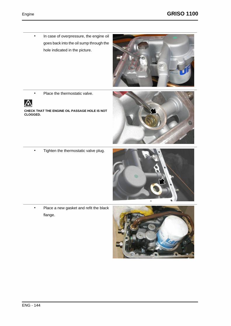
• In case of overpressure, the engine oil
goes back into the oil sump through the
hole indicated in the picture.
• Place the thermostatic valve.
CHECK THAT THE ENGINE OIL PASSAGE HOLE IS NOTCLOGGED.
• Tighten the thermostatic valve plug.
• Place a new gasket and refit the black
flange.
Engine GRISO 1100
ENG - 144

• Place a new gasket and refit the mesh
filter tightening the two screws.
• Tighten the two screws.
• Place the oil sump cover.
• Tighten the four screws.
• Refit the oil sump on the base.
• Fill engine oil up to the correct level.
Blow-by
• Loosen the oil return pipe sealing joint
and remove the oil return pipe from the
crankcase.
GRISO 1100 Engine
ENG - 145

• Remove the clamp.
• Release the two straps retaining the oil
breather pipe.
• Remove the two oil breather pipes.
• Unscrew and remove the oil return pipe
positioning screw.
• Release the oil return pipe
Engine GRISO 1100
ENG - 146

• Remove the complete blow-by system.
GRISO 1100 Engine
ENG - 147

INDEX OF TOPICS
POWER SUPPLY P SUPP

Circuit diagram
Key:
1 Complete fuel pump assembly
2 Flange screw
3 Union
4 Clamp
5 Fuel pipe
6. Three-way joint
7 Clamp
8 Pipe
Injection
GRISO 1100 Power supply
P SUPP - 149

Diagram
Key:
1 Control unit
2 Ignition switch
3 Battery
4 Fuel pump
5 Coils
6 Instrument panel
7 Air temperature sensor
8. Throttle valve position sensor
9 Injectors
10 Engine temperature sensor
11 Crankshaft position sensor
12. Side stand
Power supply GRISO 1100
P SUPP - 150

13 Lambda probe
14 Fall sensor
Cylinders synchronisation
• With engine off, connect the Navigator
tool to the diagnosis connector and to
the vehicle battery.
• Turn on the scanner.
• Screw the joints connecting the vacuometer pipes on the inlet pipe holes.
• Connect the vacuometer pipes to the relative joints.
• Set the key to ON.
• Make sure there are no errors in the control unit; otherwise, solve them and repeat the
procedure.
• Make sure the left throttle is fully in.
DO NOT TOUCH THE THROTTLE ABUTMENT SCREW ORTHE THROTTLE BODY MUST BE REPLACED. CHECKTHAT THE THROTTLE RETURN CABLE IS NOT TAUT.
• The Axone should display the adjustable parameters screen page.
• Autodetect the throttle position.
GRISO 1100 Power supply
P SUPP - 151

• Turn the key to "OFF" and leave it for
at least 30 seconds.
• Turn the key back to "ON" and restore
the Axone session.
• Check that the "Throttle" value reading
is 4.7 +/- 0.2°. If the value is incorrect,
replace the control unit and repeat the
procedure from the start.
• Completely close the two by-pass
screws on the throttle bodies.
• Start the engine.
• Take the engine to the prescribe tem-
perature: 60 °C (140 °F).
• Make the engine rev at 2000/3000 rpm
and with the vacuometer check that the
difference between the two pressures
is 1 cm Hg (1.33 kPa) maximum.
If this condition is detected:
• take the engine back to idle and check
the depression values so that they are
aligned between the two cylinders.
Otherwise, open only the screw with
higher depression, using the by-pass
screws, to compensate.
If there is a larger difference:
• act on the set screw of the throttle body
connecting rod to reduce the pressure
difference in the two pipes.
• Repeat the procedure "Throttle posi-
tion self-acquisition" as explained
above.
• Take the engine back to idle and check
the depression values so that they are
aligned between the two cylinders.
• Otherwise, open only the screw with
higher depression, using the by-pass
screws, to compensate.
Power supply GRISO 1100
P SUPP - 152

Recovery function
If the signal of the following sensors is interrupted, the control unit determines some values to keep the
engine running or it uses a different parameter. The instrument panel and the Axone also signal the
problem.
RECOVERY FUNCTIONSpecification Desc./Quantity
air temperature 25 °C (77 °F)engine temperature 30 °C (86 °F)
with linear increase from the air temperature at ignitionbarometric pressure 1010 hPa
throttle valve potentiometer 2.9° at idle, otherwise variable.idle motor fixed value variable depending on the vehicle
Using axone for injection system
Injection
Iso screen page
ISO
This screen page shows general data regarding
the control unit, for example software type, map-
ping, control unit programming date
ISO DISPLAYSpecification Desc./Quantity
Mapping -
GRISO 1100 Power supply
P SUPP - 153
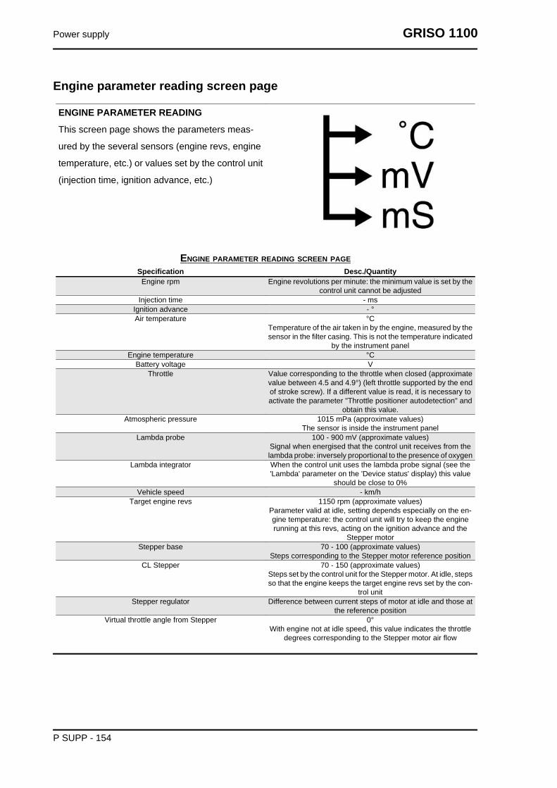
Engine parameter reading screen page
ENGINE PARAMETER READING
This screen page shows the parameters meas-
ured by the several sensors (engine revs, engine
temperature, etc.) or values set by the control unit
(injection time, ignition advance, etc.)
ENGINE PARAMETER READING SCREEN PAGESpecification Desc./QuantityEngine rpm Engine revolutions per minute: the minimum value is set by the
control unit cannot be adjustedInjection time - ms
Ignition advance - °Air temperature °C
Temperature of the air taken in by the engine, measured by thesensor in the filter casing. This is not the temperature indicated
by the instrument panelEngine temperature °C
Battery voltage VThrottle Value corresponding to the throttle when closed (approximate
value between 4.5 and 4.9°) (left throttle supported by the endof stroke screw). If a different value is read, it is necessary toactivate the parameter "Throttle positioner autodetection" and
obtain this value.Atmospheric pressure 1015 mPa (approximate values)
The sensor is inside the instrument panelLambda probe 100 - 900 mV (approximate values)
Signal when energised that the control unit receives from thelambda probe: inversely proportional to the presence of oxygen
Lambda integrator When the control unit uses the lambda probe signal (see the'Lambda' parameter on the 'Device status' display) this value
should be close to 0%Vehicle speed - km/h
Target engine revs 1150 rpm (approximate values)Parameter valid at idle, setting depends especially on the en-gine temperature: the control unit will try to keep the enginerunning at this revs, acting on the ignition advance and the
Stepper motorStepper base 70 - 100 (approximate values)
Steps corresponding to the Stepper motor reference positionCL Stepper 70 - 150 (approximate values)
Steps set by the control unit for the Stepper motor. At idle, stepsso that the engine keeps the target engine revs set by the con-
trol unitStepper regulator Difference between current steps of motor at idle and those at
the reference positionVirtual throttle angle from Stepper 0°
With engine not at idle speed, this value indicates the throttledegrees corresponding to the Stepper motor air flow
Power supply GRISO 1100
P SUPP - 154

Device status screen page
DEVICE STATUS
This screen page shows the status (usually ON/
OFF) of the vehicle devices or the operation con-
dition of some vehicle systems (for example, lamb-
da probe functioning status).
DEVICE STATUSSpecification Desc./QuantityEngine status ON/run/power-latch/stopped
operation conditionsThrottle position Released / pressed
indicates if the throttle potentiometer is open or closedStand Retracted / extended
indicates the position of the side stand (only with gear engaged)Ignition Enabled / disabled
indicates if the control unit consents engine start-upRUN / STOP switch Run / stop
indicates the position of the safety switchClutch No / Yes
indicates the clutch sensor statusGear engaged No / Yes
indicates the gear sensor statusfall sensor Normal / Tip over
indicates the vehicle fall sensor statusLambda Open loop / Closed loop
Indicates if the control unit is using (CLOSED) the lambdaprobe signal to keep the stoichiometric combustion. At idle
CLOSED only if: Air T over 20°C (68°F) and engine T over 30°C (86°F) and engine on for at least 2-3 minutes
Synchronisation Synchronised / Not synchronisedIndicates if the control unit detects the revolution sensor signal
correctly
Devices activation screen page
DEVICES ACTIVATION
This screen page is used to delete errors in the
control unit memory and to activate some systems
controlled by the control unit.
DEVICES ACTIVATIONSpecification Desc./Quantity
Left coil operation for 2.5 m, 5 times
GRISO 1100 Power supply
P SUPP - 155

Specification Desc./QuantityRight coil operation for 2.5 m, 5 times
Left injector Operation for 4 m, 5 timesRight injector Operation for 4 m, 5 timesError clearing By pressing the 'enter' button, the stored errors (MEM) become
part of the historical data (STO). In the next connection be-tween the Navigator and the control unit, the historical errors
(STO) are no longer shownFuel pump Operation for 30''
Stepper control <span style="FONT-SIZE: 12pt; FONT-FAMILY: "Times NewRoman"; mso-fareast-font-family: "Times New Roman"; mso-
ansi-language: IT; mso-fareast-language: IT; mso-bidi-lan-guage: AR-SA">For 4'' advancement command of 32 steps, forthe next 4'' retrocession command of 32 steps and so on for
30''
Errors display screen page
ERRORS DISPLAY
This screen page shows potential errors detected
in the vehicle (ATT) or stored in the control unit
(MEM) and it allows to check error clearing (STO).
ERRORS DISPLAYSpecification Desc./Quantity
Pressure sensor Possible short circuit in the earth lead, battery or open circuit:recovery function noticeable for customer. Careful with the air
pressure sensor in the instrument panelAir temperature Possible short circuit in the earth lead, battery or open circuit:
recovery function hardly noticeable for customer.Engine temperature Possible short circuit in the earth lead, battery or open circuit:
recovery function.Throttle actuator position sensor Possible short circuit in the earth lead, battery or open circuit:
recovery function noticeable for customer.Lambda probe Possible short circuit on the earth lead, battery or open circuit
or plausibility: recovery function hardly noticeable for customer.Left injector Possible short circuit in the earth lead, battery or open circuit.
If both injectors do not work, the engine does not workRight injector Possible short circuit in the earth lead, battery or open circuit.
If both injectors do not work, the engine does not workFuel pump relay Possible short circuit in the earth lead, battery or open circuit:
the engine does not start.Left coil Possible short circuit in the earth lead, battery or open circuit.
If both coils do not work, the engine does not work.Right coil Possible short circuit in the earth lead, battery or open circuit.
If both coils do not work, the engine does not work.Idle regulator Possible short circuit in the earth lead, battery or open circuit:
recovery function noticeable for the customer due to no idlemanagement
Battery voltage Battery voltage detected is too low (7V) or too high (16V) for acertain period
Starter diagnosis Possible short circuit in the earth lead, battery or open circuit.Engine revolution sensor Possible open circuit.
Lambda heater Possible short circuit in the earth lead, battery or lambda probeheating circuit open.
SPEED SENSOR
Power supply GRISO 1100
P SUPP - 156

Specification Desc./QuantityCAN line diagnosis <span style="FONT-SIZE: 12pt; FONT-FAMILY: "Times New
Roman"; mso-fareast-font-family: "Times New Roman"; mso-ansi-language: IT; mso-fareast-language: IT; mso-bidi-lan-
guage: AR-SA">Possible error on line CAN: short circuit or linebreak or no signal or plausibility error detected.
RAM memory Possible internal control unit error. Also check the control unitsupply and earth connections
ROM memory Possible internal control unit error. Also check the control unitsupply and earth connections
Microprocessor Possible internal control unit error. Also check the control unitsupply and earth connections
Checksum EPROM Possible internal control unit error. Also check the control unitsupply and earth connections
Adjustable parameters screen page
ADJUSTABLE PARAMETERS
This screen page is used to adjust some control
unit parameters.
ADJUSTABLE PARAMETERSSpecification Desc./Quantity
Throttle positioner autodetection Allows the control unit to detect the closed throttle position: justpress the enter button
GRISO 1100 Power supply
P SUPP - 157

INDEX OF TOPICS
SUSPENSIONS SUSP

Front
Removing the front wheel
• Working from both sides, undo and re-
move the two fixing screws from the
front brake callipers and remove them
from their seats.
• Hold the vehicle front part.
• Unscrew and remove the wheel axle
fixing nut and collect the sealing wash-
er.
• Working from both sides, loosen the
screws on the wheel bolt clamps.
• Tap the wheel axle slightly with a rub-
ber mallet so that the hole on the op-
posite side is exposed.
GRISO 1100 Suspensions
SUSP - 159

• Remove the wheel axle by inserting a
screwdriver in the holes on the pin.
• During extraction, support the wheel
and then remove it.
• Collect the spacer from the front wheel
right side.
Front fork
Suspensions GRISO 1100
SUSP - 160

Diagram
Key:
1 Locking ring
2 Spring preloading regulator
3 Spring preloading pusher
4 Sleeve upper cover
5 Washer
6 Slider
7 Complete pumping member
8 Centring bushing
9 Spring pressing pipe
10 Spring
11 Spring support washer
12 Lower collar
GRISO 1100 Suspensions
SUSP - 161

13 Sleeve
14 Sliding bushing
15 Guide bushing
16 Stop washer
17 Gasket
18 Snap ring
19 Dust guard gasket
20 Wheel holder stem
21 Copper washer
22 Central screw
23 O-ring
24 O-ring
Adjustment
The standard front fork setting is adjusted to suit
most low and high speed riding conditions, wheth-
er the vehicle is partially or fully loaded. This set-
ting can also be customised based on vehicle use.CAUTIONSPORTS SETTING MAY BE USED ONLY FOR OFFICIALCOMPETITIONS TO BE CARRIED OUT ON TRACKS,AWAY FROM NORMAL ROAD TRAFFIC AND WITH THEAUTHORISATION OF THE RELEVANT AUTHORITIES.IT IS STRICTLY FORBIDDEN TO USE SPORT SETTINGSAND RIDE THE VEHICLE SO SET ON ROADS AND MO-TORWAYS.
FOR ADJUSTMENT, ALWAYS START FROM THE MOSTRIGID SETTING (SET SCREWS (1 - 2) FULLY CLOCKWISE).USE THE NOTCHES ON SET SCREWS (1 - 2) AS REFER-ENCES TO ADJUST HYDRAULIC COMPRESSION AND RE-BOUND DAMPING.TURN THE SET SCREWS (1 - 2) GRADUALLY BY 1/8 OF ATURN AT A TIME.
FRONT FORK ADJUSTMENTSpecification Desc./Quantity
Standard rebound damping adjustment, screw (1) Open (**) 1.25 turn from fully closed (*)Hydraulic rebound damping adjustment for sports use, screw
(1)Open (**) 0.5 - 1 turn from fully closed (*)
Standard compression damping adjustment, screw (2) Open (**) (S) 1 turn from fully closed (*) (H)Hydraulic compression damping adjustment for sports use,
screw (2)Open (**) (S) 0.5 - 1 turn from fully closed (*) (H)
Spring preloading, nut (3) Open (**) 4 - 5 protrusion notches from fully closed (*)Stems (A) protrusion from top plate (excluding cover) (standard
adjustment)4 protrusion notches
Suspensions GRISO 1100
SUSP - 162

Specification Desc./QuantityTake your vehicle only to a Moto Guzzi Official Dealer for this
type of adjustment.Stems (A) protrusion from top plate (excluding cover) (sports
use adjustment)5 protrusion notches
Take your vehicle only to a Moto Guzzi Official Dealer for thistype of adjustment.
Removing the fork legs
• Remove the front mudguard.
• Support the fork stem and loosen the
screws on the upper and lower plates.
• Slide off the fork stem.
See alsoRemoving thefront wheel
Draining oil
• Lock the sleeve in a vice with the spe-
cific tool (code AP8140149).
• Set the minimum spring preloading.
Specific toolingAP8140149 Protection for fitting operations
GRISO 1100 Suspensions
SUSP - 163

• Unscrew the sleeve top cap.
• Lock the calliper mounting bracket in a
vice paying attention not to damage it.
• Fit the tool on the spring joint.
Specific toolingAP8140147 Spacer tool
• Push the tool against the spring and
compress it. Fit the spacer of the tool
under the cartridge lock nut.
Specific toolingAP8140148 Spacer-piston separating plate
Suspensions GRISO 1100
SUSP - 164

• Loosen the cap by the key grip and by
making the lock nut turn.
• Remove the complete cap.
• Remove the spacer and the washer.
• Press down and force the spring to
compress. Remove the spacer.
GRISO 1100 Suspensions
SUSP - 165

• Remove the spring joint.
• Drain off oil into a collecting container
and remove the spring.
Disassembling the fork
• After emptying the oil, fasten the cal-
liper mounting bracket of the fork stan-
chion in a vice.
• Position the washer and the lower
spacer.
Suspensions GRISO 1100
SUSP - 166

• Unscrew the cartridge fixing screw on
the fork feet.
• Retrieve the centring bushing.
• Slide off the dust scraper from the
sleeve using a screwdriver as a lever.
• During this operation, pay attention not
to damage the sleeve rim.
• Remove the retainer ring.
• Take out the sleeve from the stem us-
ing the stem as a hammer puller.
GRISO 1100 Suspensions
SUSP - 167
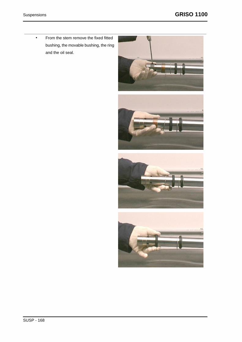
• From the stem remove the fixed fitted
bushing, the movable bushing, the ring
and the oil seal.
Suspensions GRISO 1100
SUSP - 168

• Remove the ring and the dust guard.
See alsoDraining oil
Checking the components
Stem
Check the sliding surface for scorings and/or scratches.
These scorings can be eliminated by rubbing them with wet sandpaper (grain 1).
If the scorings are deep, replace the stem.
Use a dial gauge to check that the stem bending is below the limit value.
If over the value, replace the stem.CAUTION
A BENT STEM SHOULD NEVER BE STRAIGHTENED BECAUSE ITS STRUCTURE WOULD BEWEAKENED AND USING THE VEHICLE MAY BECOME DANGEROUS.
CharacteristicBending limit:
0.2 mm (0.00787 in)
Sleeve
Check that there are no damages and/or cracks; otherwise, replace it.
Spring
Check that the spring is in good conditions. Check that the spring length is within the limit value.
Replace the spring if its length does not fall within the limit values.
SPRING MINIMUM LENGTH WHEN UNLOADED: 284 mm (11.2 in)
Check that the following components are in good
conditions:
• sliding bushing;
• guide bushing;
GRISO 1100 Suspensions
SUSP - 169

• piston.
If there are signs of excessive wear or damage, replace the affected component.CAUTION
REMOVE ANY IMPURITY IN THE BUSHINGS, TAKING CARE NOT TO SCRATCH THEIR SUR-FACE.
Replace the following components with new ones:
• gasket;
• dust guard gasket;
• the two O-rings on the regulator.
Reassembling the fork
• Lock the stem in a vice without dam-
aging the surface.
• Protect the bearing tube end with ad-
hesive tape.
• Lubricate the sliding edges with fork oil
or sealing grease.
• Fit on the slider the dust scraper, the
retainer ring and the seal ring.
Suspensions GRISO 1100
SUSP - 170

• The sealing ring must be placed with
the stamped part facing the dust gaiter.
• Fit the ring, the movable bushing and,
after removing the tape, fit the fixed
bushing.
GRISO 1100 Suspensions
SUSP - 171

• Fit the sleeve on the stem and set the
oil seal into position with the aid of the
specific tool.
Specific toolingAP8140149 Protection for fitting operations
• Insert the retainer ring in its position.
Suspensions GRISO 1100
SUSP - 172
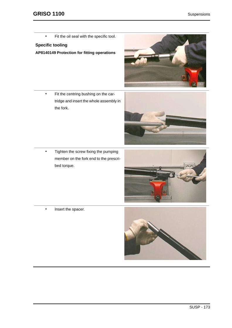
• Fit the oil seal with the specific tool.
Specific toolingAP8140149 Protection for fitting operations
• Fit the centring bushing on the car-
tridge and insert the whole assembly in
the fork.
• Tighten the screw fixing the pumping
member on the fork end to the prescri-
bed torque.
• Insert the spacer.
GRISO 1100 Suspensions
SUSP - 173

Filling oil
• Place the sleeve upright in a vice fitted
with protection shoes.
• Compress the sleeve in the stem.
• Pour part of the fork oil into the sleeve.
• Wait some minutes until the oil fills all
the ducts.
• Pour the remaining oil.
• Pump out oil a few times.
• Measure the air gap between the oil
level and the rim.
THE SLEEVE MUST BE PERFECTLY UPRIGHT IN ORDERTO MEASURE THE CORRECT OIL LEVEL. THE OIL LEVELMUST BE THE SAME IN BOTH STANCHIONS.
CharacteristicFork oil520 ± 2.5 cm³ (31.7 ± 0.15 in) (for each stem)
Oil level (from sleeve rim, without the springand washer)114 mm (4.49 in).
• Place the washer.
• Fit the spring.
Suspensions GRISO 1100
SUSP - 174

• Fit the complete preloading pipe.
• Fit the specified tool on the spring cou-
pling so that the cartridge stem is
locked in position.
Specific toolingAP8140147 Spacer tool
8140148 Spacer / pumping member separatingplate
• Position the spacer and the washer.
GRISO 1100 Suspensions
SUSP - 175
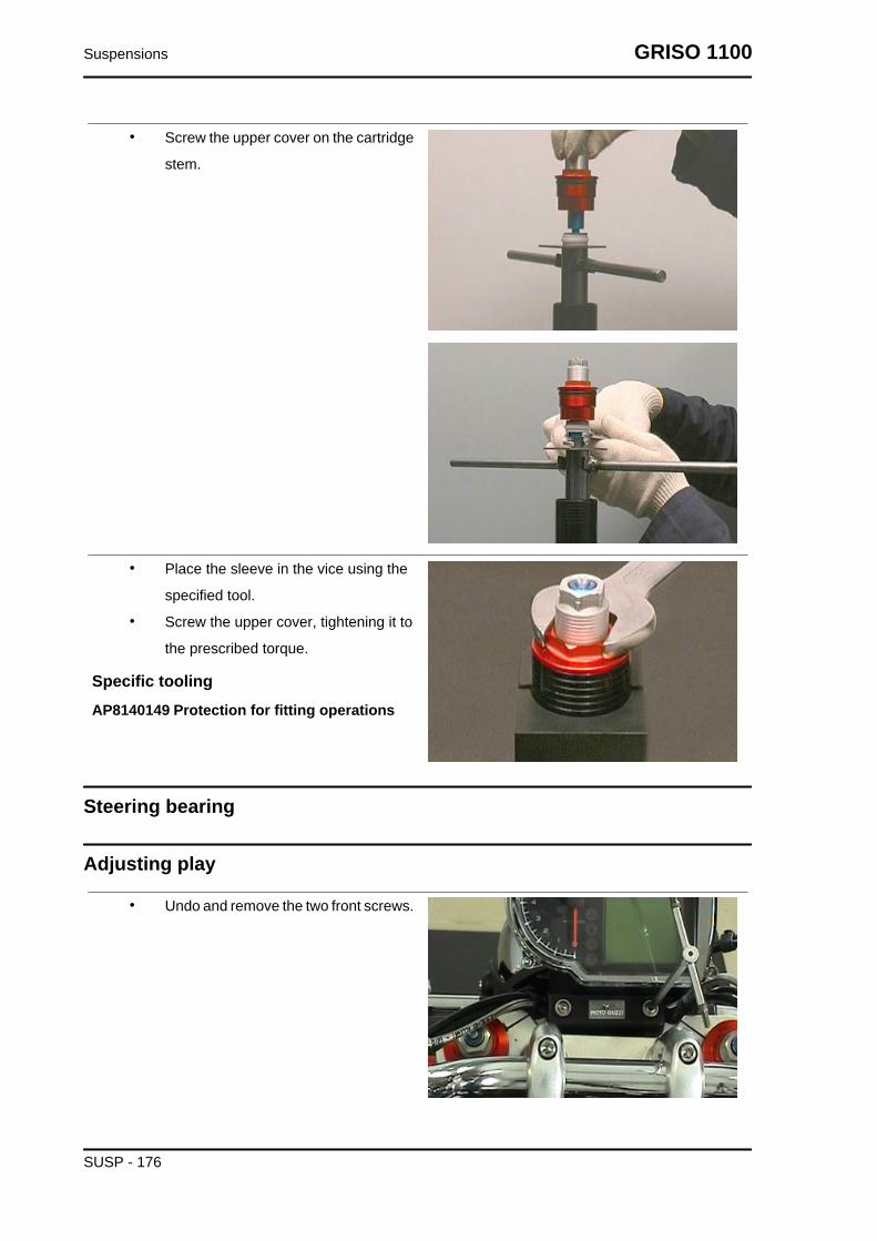
• Screw the upper cover on the cartridge
stem.
• Place the sleeve in the vice using the
specified tool.
• Screw the upper cover, tightening it to
the prescribed torque.
Specific toolingAP8140149 Protection for fitting operations
Steering bearing
Adjusting play
• Undo and remove the two front screws.
Suspensions GRISO 1100
SUSP - 176

• Undo and remove the two external
screws and move the instrument panel
forwards.
• Unscrew and remove the screws and
collect the U-bolts, holding the handle-
bar.
• Move the handlebar forward without
tilting the clutch and the front brake flu-
id reservoirs.
• Undo and remove the screw.
• Collect the right handlebar support.
• Unscrew and remove the fork upper
plate cover; collect the shim.
GRISO 1100 Suspensions
SUSP - 177
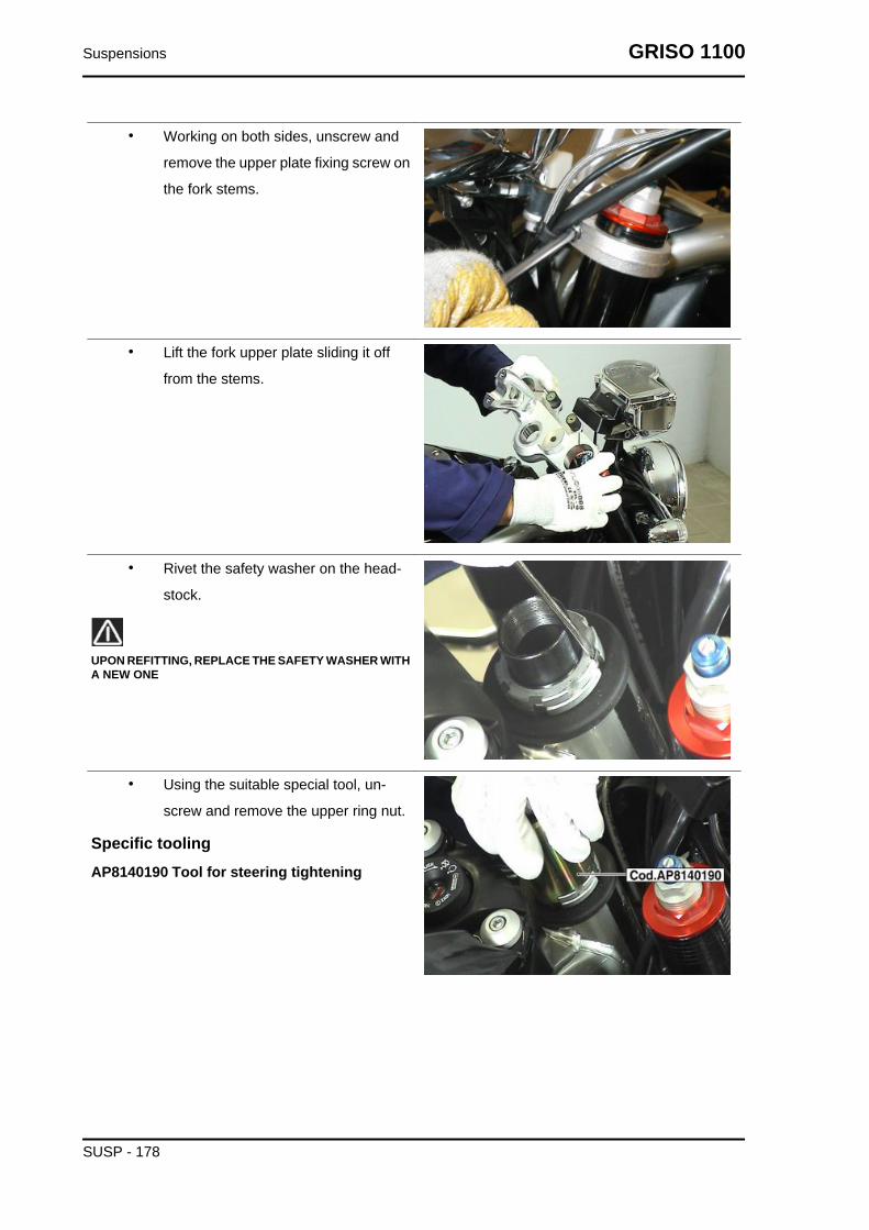
• Working on both sides, unscrew and
remove the upper plate fixing screw on
the fork stems.
• Lift the fork upper plate sliding it off
from the stems.
• Rivet the safety washer on the head-
stock.
UPON REFITTING, REPLACE THE SAFETY WASHER WITHA NEW ONE
• Using the suitable special tool, un-
screw and remove the upper ring nut.
Specific toolingAP8140190 Tool for steering tightening
Suspensions GRISO 1100
SUSP - 178
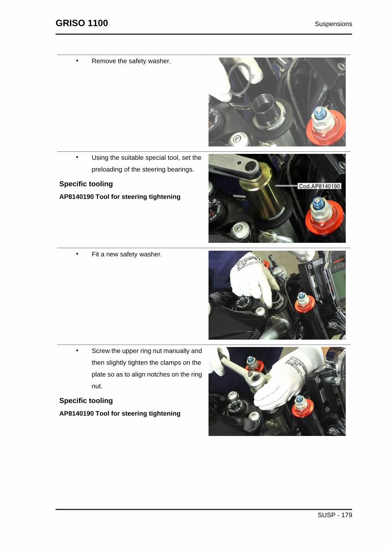
• Remove the safety washer.
• Using the suitable special tool, set the
preloading of the steering bearings.
Specific toolingAP8140190 Tool for steering tightening
• Fit a new safety washer.
• Screw the upper ring nut manually and
then slightly tighten the clamps on the
plate so as to align notches on the ring
nut.
Specific toolingAP8140190 Tool for steering tightening
GRISO 1100 Suspensions
SUSP - 179

• Rivet the tongues of the new safety
washer.
• Fit the fork upper plate on the stems.
Rear
Removing the rear wheel
• Support the vehicle from the rear with
an adequate stand.
• Remove the cover.
• Engage the first gear.
• Undo and remove the four screws, col-
lect the spacers and the dust-protec-
tion ring.
• Remove rear wheel.
Suspensions GRISO 1100
SUSP - 180

Shock absorbers
Removing
• Secure the vehicle handlebar from the
front with a hoist.
• Support the vehicle from below with a
suitable underpan jack.
• Support the vehicle from the front with
a suitable stand.
GRISO 1100 Suspensions
SUSP - 181
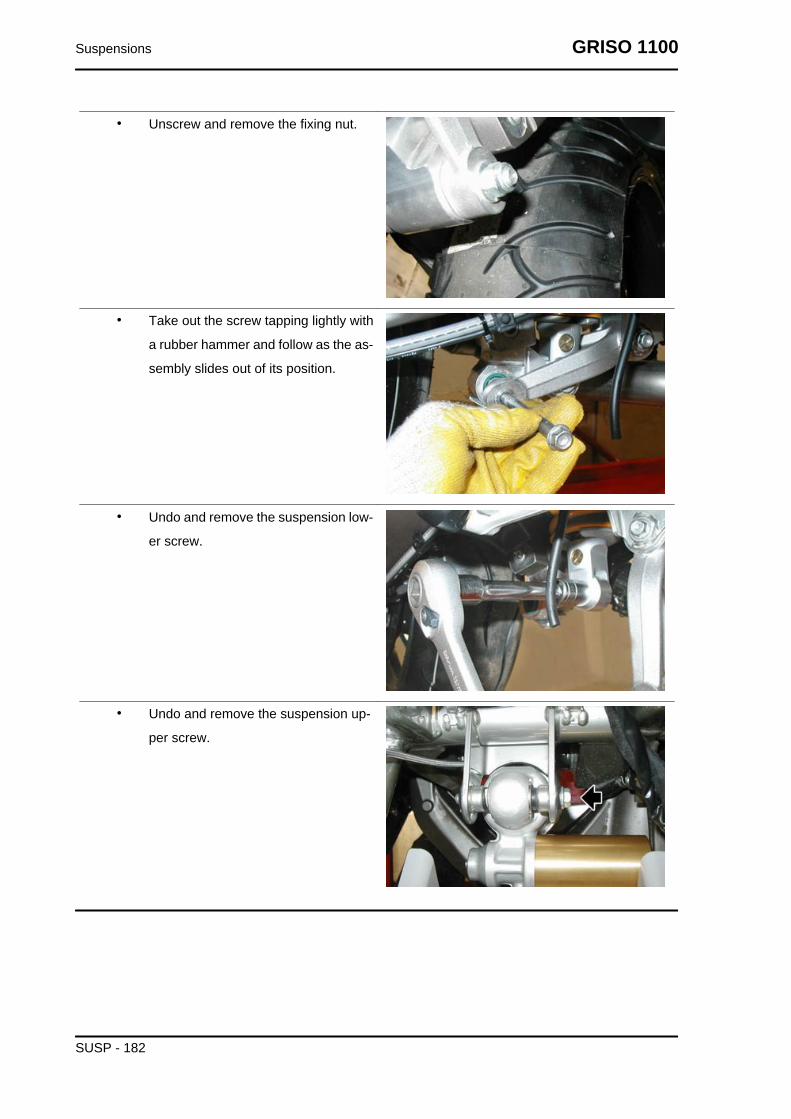
• Unscrew and remove the fixing nut.
• Take out the screw tapping lightly with
a rubber hammer and follow as the as-
sembly slides out of its position.
• Undo and remove the suspension low-
er screw.
• Undo and remove the suspension up-
per screw.
Suspensions GRISO 1100
SUSP - 182

INDEX OF TOPICS
CHASSIS CHAS

Swinging arm
Removing
• To remove the swingarm, first remove
both footrest supporting plates and the
exhaust silencer.
• Slide off the rear brake calliper from the
disc and release the brake pipe.
• Remove the cover.
• Engage the first gear.
• Unscrew and remove the four screws,
collecting the spacers and the dust pro-
tection ring.
• Remove the rear wheel.
• Unscrew and remove the nut fixing the
reaction rod.
• Remove the screw.
• Fix the reaction rod to the chassis with
a clamp.
Chassis GRISO 1100
CHAS - 184

• Remove the clamp from the dust guard
cap.
• Loosen the two swingarm terminal
screws.
• Unscrew and remove the fixing nut of
the connecting rod assembly and col-
lect the screw.
• Disconnect the speed sensor connec-
tor and release the cable from the
clamps on the chassis.
GRISO 1100 Chassis
CHAS - 185

• Loosen the ring nut.
Specific toolingGU14912603 Hook spanner for fixing ring nutof the clutch shaft internal body
• Helped by a second operator, remove
the pin and remove the swingarm to-
gether with the cardan shaft.
Checking
• Check that the universal joint is not
damaged, the gear teeth inserting in
the sleeve grooves and the grooves on
the joint are not deformed or damaged;
otherwise, replace the joint.
• Check that the rubber bellows are not
cut or pierced; otherwise, replace it.
• Check that the fork pin threads and the
fork fixing nuts are not damaged, de-
formed or flattened; otherwise, replace
them.
• Check that the sleeve grooves are not
damaged, deformed or deteriorated;
otherwise, replace the sleeve.
• Check that the sleeve outer toothing
and grooves are not damaged.
Chassis GRISO 1100
CHAS - 186

Installing
• Spread a thin layer of lubricating
grease all along the swingarm pin.
• Fit the ring nut in the swingarm pin and
screw it manually.
• Working from both sides, grease the
cardan shaft cables with the recom-
mended product from the recommen-
ded products table.
• Block the swingarm, insert the univer-
sal joint, align the holes and, at the
same time, helped by a second opera-
tor, insert the pin completely.
• Tighten the swingarm pin.
• Use the suitable box-spanner to tight-
en the ring nut.
Specific toolingGU14912603 Hook spanner for fixing ring nutof the clutch shaft internal body
• Tighten the two screws of the swing-
arm clamp.
GRISO 1100 Chassis
CHAS - 187
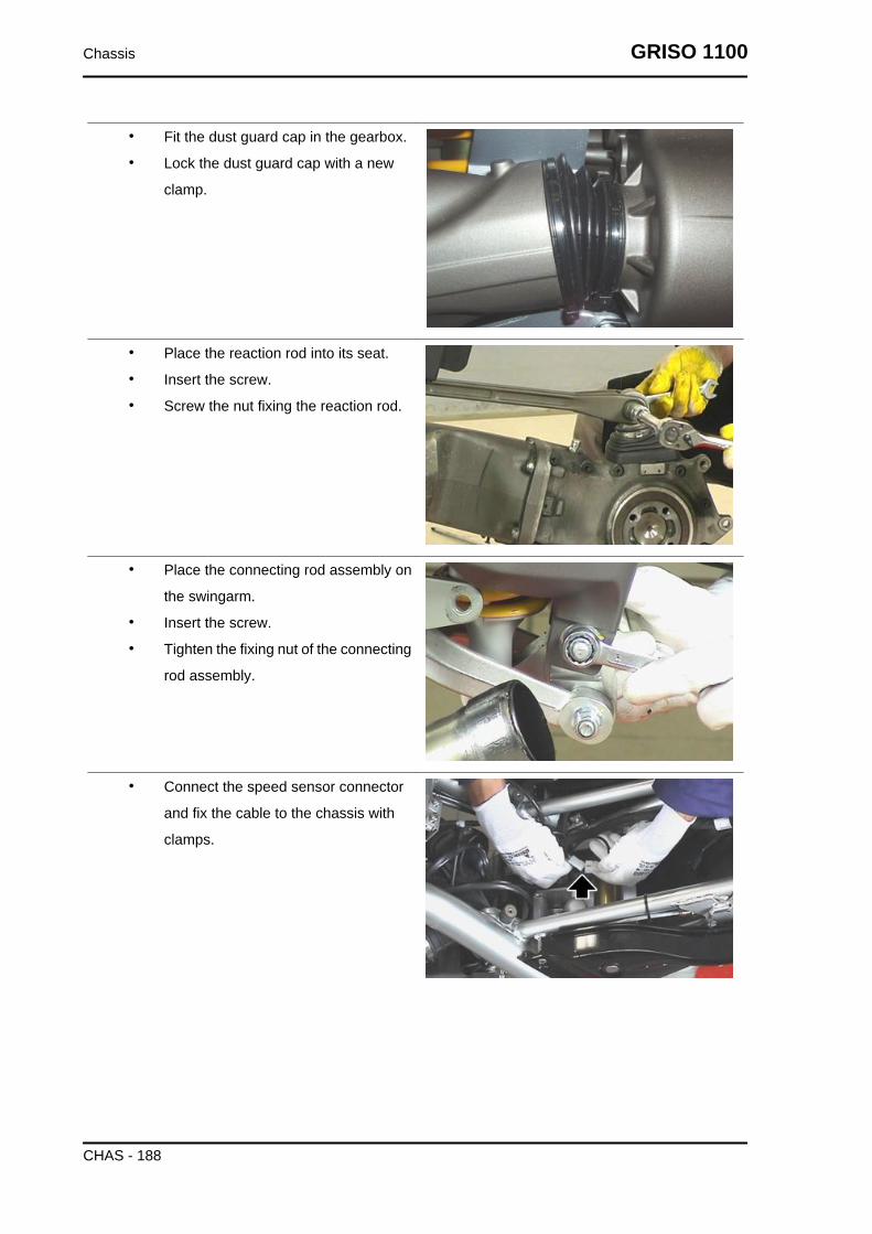
• Fit the dust guard cap in the gearbox.
• Lock the dust guard cap with a new
clamp.
• Place the reaction rod into its seat.
• Insert the screw.
• Screw the nut fixing the reaction rod.
• Place the connecting rod assembly on
the swingarm.
• Insert the screw.
• Tighten the fixing nut of the connecting
rod assembly.
• Connect the speed sensor connector
and fix the cable to the chassis with
clamps.
Chassis GRISO 1100
CHAS - 188
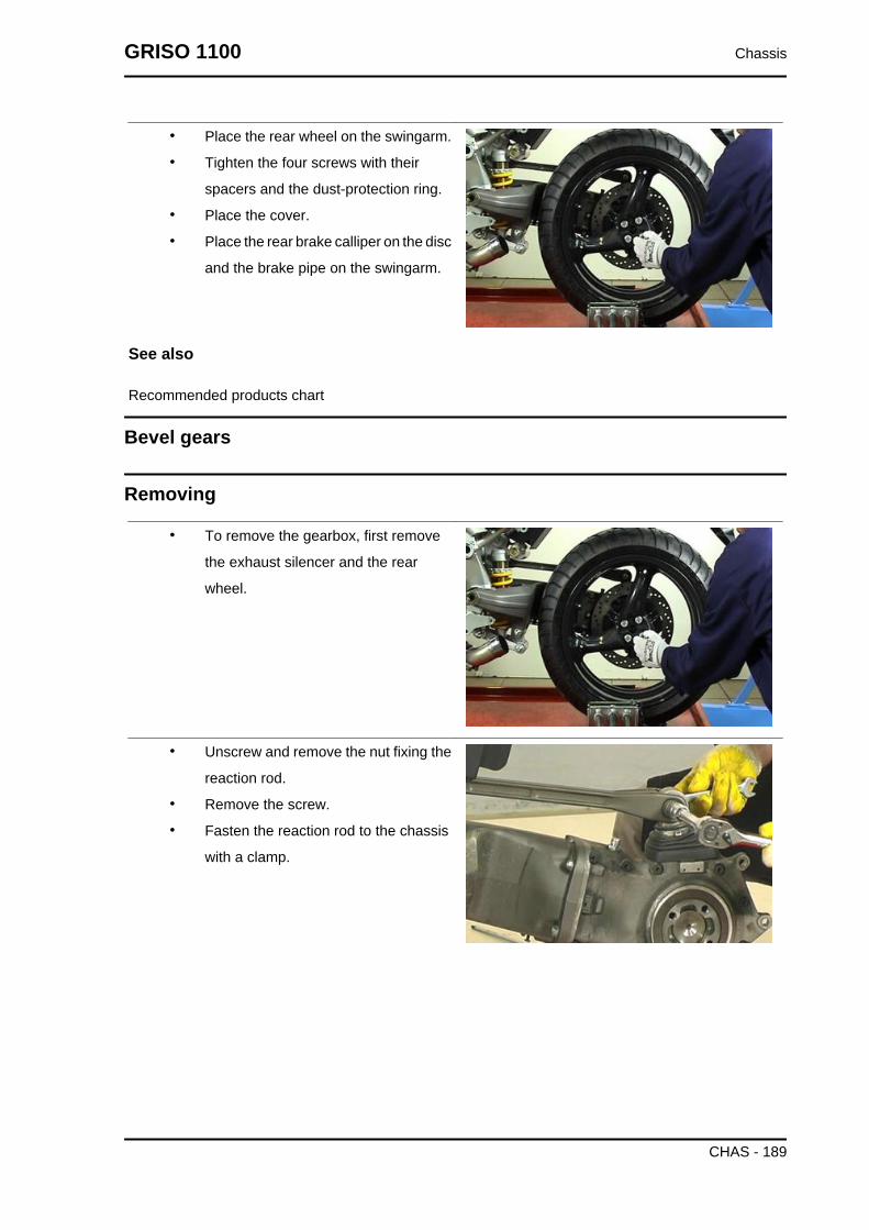
• Place the rear wheel on the swingarm.
• Tighten the four screws with their
spacers and the dust-protection ring.
• Place the cover.
• Place the rear brake calliper on the disc
and the brake pipe on the swingarm.
See also
Recommended products chart
Bevel gears
Removing
• To remove the gearbox, first remove
the exhaust silencer and the rear
wheel.
• Unscrew and remove the nut fixing the
reaction rod.
• Remove the screw.
• Fasten the reaction rod to the chassis
with a clamp.
GRISO 1100 Chassis
CHAS - 189

• Undo and remove the four screws.
• Remove the transmission casing slid-
ing off the universal joint.
CheckingCasing unit removal
Chassis GRISO 1100
CHAS - 190

Casing unit removal
Remove the cover (20).
Remove the plug (3) to drain out the oil.
Lift the cap (10).
Remove the clamps (9) and (11).
Remove the cap (14).
Remove the screws (16).
GRISO 1100 Chassis
CHAS - 191

Collect the ring (15).
Remove the screws (7).
Remove the casing (4).
Remove the clamp (12).
Remove the cap (14).
Chassis GRISO 1100
CHAS - 192

Collect the ring (13).
Remove the support unit (8).
Casing unit fitting
Casing unit fitting
Assemble the dowel pins to the casing with the
buffer and a hammer.
Assemble the casing to the special fastening tool.
Clean the casing faying surfaces carefully.
GRISO 1100 Chassis
CHAS - 193
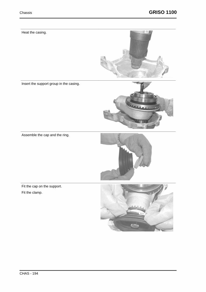
Heat the casing.
Insert the support group in the casing.
Assemble the cap and the ring.
Fit the cap on the support.
Fit the clamp.
Chassis GRISO 1100
CHAS - 194

Screw the clamp with the specific pliers.
Apply the prescribed sealant to the casing.
Fit a new sealing ring using the buffer.
Lubricate the sealing ring.
Assemble two centring stud bolts with M8 thread
in the threaded holes of the casing as shown in the
picture.
GRISO 1100 Chassis
CHAS - 195

Fit the casing.
Remove the two dowel pins.
Assemble the fixing screws (7).
Tighten the screws (7) to the prescribed torque.
Remove excessive sealant.
Assemble the ring to the casing.
Tighten the fixing screws to the prescribed torque.
Chassis GRISO 1100
CHAS - 196
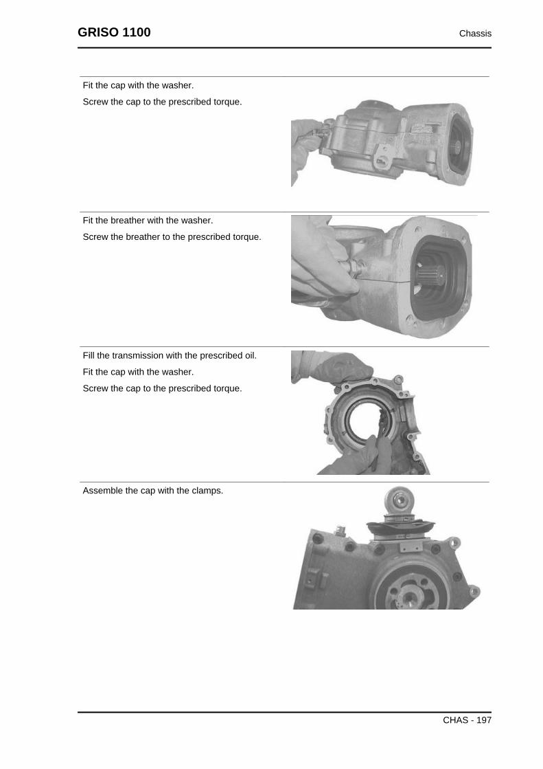
Fit the cap with the washer.
Screw the cap to the prescribed torque.
Fit the breather with the washer.
Screw the breather to the prescribed torque.
Fill the transmission with the prescribed oil.
Fit the cap with the washer.
Screw the cap to the prescribed torque.
Assemble the cap with the clamps.
GRISO 1100 Chassis
CHAS - 197

Fit the cap in its seat.
Wheel axle unit
Gruppo asse ruota
Removal
Remove the bearing from the wheel axle with a
suitable extractor.
Turn the unit over.
Remove the bearing from the wheel axle with a
suitable extractor.
FITTING
Heat the bearings to 100°C (212 °F).
Chassis GRISO 1100
CHAS - 198

Assemble the bearings to the wheel axle.
Turn the unit over.
Assemble the bearings to the wheel axle.
Pinion unit
Pinion unit
Removal
Remove the stop ring (1) from the ring nut.
Unscrew the ring nut (2) with the special spanner
(s4).
GRISO 1100 Chassis
CHAS - 199

Remove the ring nut (2) and remove the sealing
ring from the ring nut.NOTETHIS OPERATION DESTROYS THE SEALING RING.
Assemble the sealing ring (3) to the ring nut (2)
with the buffer CA715855 (see Fig.1) and a ham-
mer.
Lubricate the sealing ring (3).
Assemble the ring nut (2).
Chassis GRISO 1100
CHAS - 200

Tighten the ring nut (2) with the special spanner
(s4) to the prescribe torque.
Insert the stop ring (1) in the ring nut (2) in the in-
dicated direction.
Assembly position of the stop ring (1).
CAUTIONMAKE SURE THE STOP RING IS IN ITS SEAT.
Support unit
GRISO 1100 Chassis
CHAS - 201

Support unit
Removal
Remove the bushing (1) with a punch.
Turn the support (5) over and remove the other
bushing (8).
Remove the sealing rings (2) and (7) with a screw-
driver.
Remove the stop rings (3) and (6) from the support
(5) with suitable pliers.NOTETHIS OPERATION DESTROYS THE SEALING RING.
Chassis GRISO 1100
CHAS - 202

Remove the ball joint (4) with a suitable buffer and
a rubber hammer.
FITTING
Fit the stop ring (6) in the support (5) with suitable
pliers.
Turn the support (5) over.
Assemble the ball joint (4) with the buffer and a
rubber hammer.
Fit the stop ring (3) in the support (5) with suitable
pliers.
GRISO 1100 Chassis
CHAS - 203

Manually assemble the new sealing rings (2) and
(7).
Assemble the bushing (1).
Drive the bushing (1) in with a plastic hammer.
Turn the support (5) over and assemble the other
bushing (8).
TROUBLESHOOTINGPossible Cause Operation
1. Fitting error of the radial seal or seal damaged 2. Slidingsurface of the wheel axle seal spoiled or damaged
1. Replace the sealing ring and fit it correctly with the suitabletool
2. Replace the wheel axle1. Casing not sealed 2. Closing screws of the casing shells not
tightened to the prescribed torque1. Open the casing shells, clean the surfaces, seal and reas-
semble the casing shells2. Tighten the closing screws to the correct torque
1. Dirt between the sealing ring and the casing 2. A used seal-ing ring has been fitted 3. Plug not tightened to the prescribed
torque
1. Clean and tighten to the correct torque2. Replace the sealing ring
3. Tighten the plug to the correct torque1. Cap damaged 2. Retaining clamp or closing cover loose 3.Fitting error of the radial seal or seal damaged 4. Sliding sur-
face of the wheel spacer spoiled or damaged
1. Replace the cap2. Screw the clamp with suitable pliers
3. Replace the sealing ring and fit it correctly with the suitabletool
4. Replace the spacer1. Cap damaged 2. Internal retaining clamp or external closing
clamp loose1. Replace the cap
2. Screw the internal or external clamp with suitable pliers1. Bevel gear pair fitting error 2. Bevel gear pair toothing spoiled
or damaged1. Replace the bevel gear pair
1. Ball bearings on the wheel axle damaged 1. Replace the wheel bearings
Chassis GRISO 1100
CHAS - 204
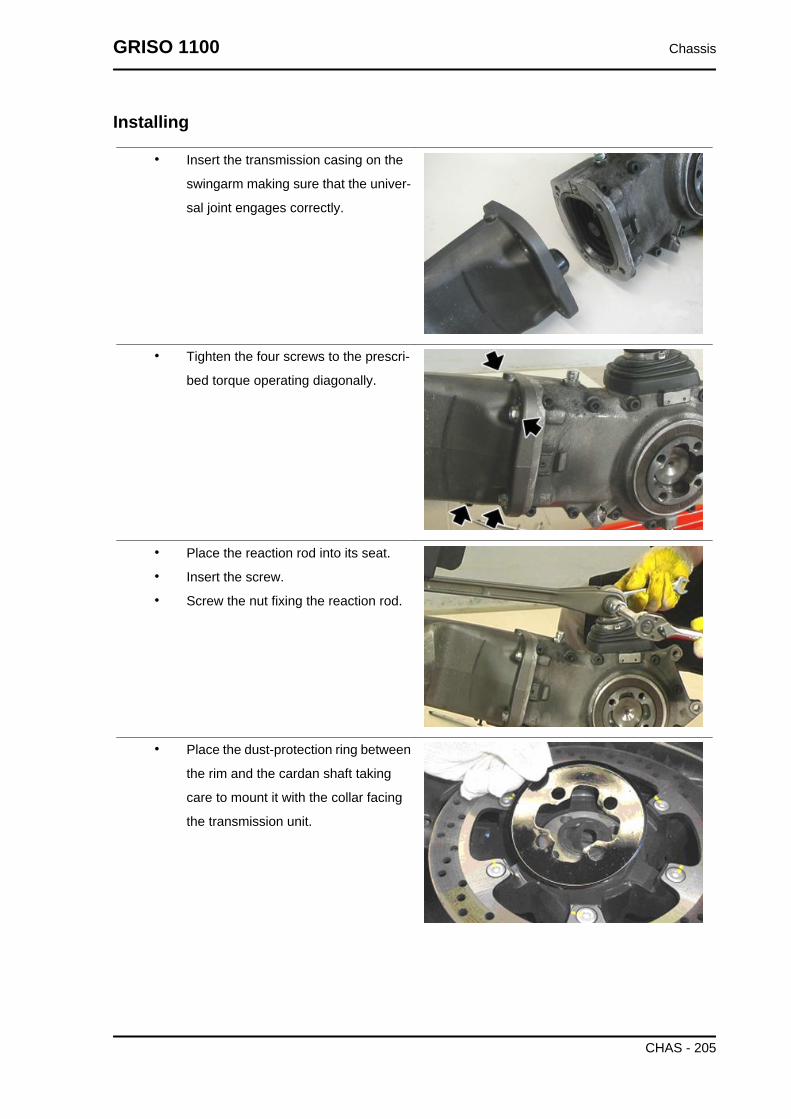
Installing
• Insert the transmission casing on the
swingarm making sure that the univer-
sal joint engages correctly.
• Tighten the four screws to the prescri-
bed torque operating diagonally.
• Place the reaction rod into its seat.
• Insert the screw.
• Screw the nut fixing the reaction rod.
• Place the dust-protection ring between
the rim and the cardan shaft taking
care to mount it with the collar facing
the transmission unit.
GRISO 1100 Chassis
CHAS - 205

• Place the rear wheel on the swingarm.
• Tighten the four screws with their
spacers and the dust-protection ring.
• Place the cover.
• Place the rear brake calliper on the disc
and the brake pipe on the swingarm.
Exhaust
Removing the tail pipe
• Loosen the sealing clamp between the
exhaust and the central manifold.
• Unscrew and remove the two front at-
tachment screws fixing the exhaust to
the chassis; collect the lock nuts.
Locking torques (N*m)Silencer to footrest support retainer 25 Nm
• Unscrew and remove the rear attach-
ment screw fixing the exhaust pipe to
the chassis; collect the lock nut, the
spacer and the washer.
DURING THIS OPERATION SUPPORT THE EXHAUST PIPESO THAT IT DOES NOT FALL.
Locking torques (N*m)
Chassis GRISO 1100
CHAS - 206

Silencer to chassis connecting pipe retainer 25Nm
• Remove the exhaust end.
Engine oil cooler
Key:
1. Complete oil radiator
2. Reduction
3. Aluminium gasket
4. Capstan screw
5. Right pipe
6. Left pipe
7. Deflector
8. M6x30 TE flanged screw
9. Washer
10. Bushing
GRISO 1100 Chassis
CHAS - 207
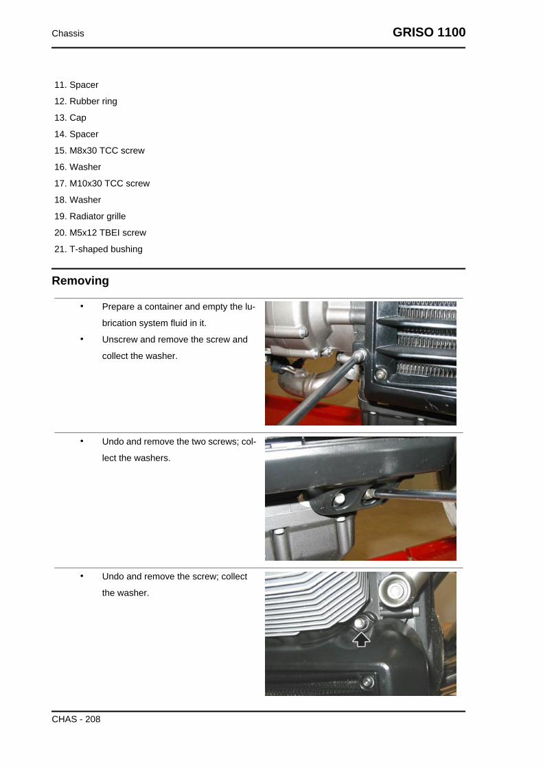
11. Spacer
12. Rubber ring
13. Cap
14. Spacer
15. M8x30 TCC screw
16. Washer
17. M10x30 TCC screw
18. Washer
19. Radiator grille
20. M5x12 TBEI screw
21. T-shaped bushing
Removing
• Prepare a container and empty the lu-
brication system fluid in it.
• Unscrew and remove the screw and
collect the washer.
• Undo and remove the two screws; col-
lect the washers.
• Undo and remove the screw; collect
the washer.
Chassis GRISO 1100
CHAS - 208

• Unscrew and remove the two screws;
collect the pipes and the four washers.
• Remove the oil cooling radiator.
GRISO 1100 Chassis
CHAS - 209

INDEX OF TOPICS
BRAKING SYSTEM BRAK SYS

Front brake pads
Removal
• Turn the pins and remove both split
pins.
• Remove both pins.
• Remove the vibration-damping plate.
• Extract one pad at a time.CAUTIONAFTER REMOVING THE PADS, DO NOT OPERATE THEBRAKE LEVER OR THE CALLIPER PLUNGERS COULDGO OUT OF THEIR SEATS RESULTING IN BRAKE FLUIDLEAKS.
GRISO 1100 Braking system
BRAK SYS - 211

Installing
• Insert two new pads, placing them so
that the holes are aligned with the cal-
liper holes.CAUTION
ALWAYS REPLACE BOTH PADS AND MAKE SURE THEYARE CORRECTLY POSITIONED INSIDE THE CALLIPER.
• Position the anti-vibration plate.
• Insert both pins.
• Position both split pins.
• Abut the plungers against the pads,
acting on the brake pump lever several
times.
• Check the brake fluid level in the res-
ervoir.
Rear brake pads
Braking system GRISO 1100
BRAK SYS - 212

Removal
• Free the brake pipe and the throttle grip
cable from the clamps.
• Undo and remove the two screws.
• Remove the brake calliper from the
disc.
• Turn the pin and pull out the split pin.
• Remove the split pin.
• Remove the pin.
GRISO 1100 Braking system
BRAK SYS - 213

• Extract one pad at a time.CAUTIONAFTER REMOVING THE PADS, DO NOT OPERATE THEBRAKE LEVER OR THE CALLIPER PLUNGERS COULDGO OUT OF THEIR SEATS RESULTING IN BRAKE FLUIDLEAKS.
Installing
• Insert two new pads, placing them so
that the holes are aligned with the cal-
liper holes.CAUTION
ALWAYS REPLACE BOTH PADS AND MAKE SURE THEYARE CORRECTLY POSITIONED INSIDE THE CALLIPER.
• Insert the pin.
• Position the split pin.
• Insert the brake calliper into the disc by
screwing in the two screws.
• Abut the plungers against the pads,
acting on the brake pump pedal sever-
al times.
• Check the brake fluid level in the res-
ervoir.
Braking system GRISO 1100
BRAK SYS - 214

Bleeding the braking system
Front
Any air trapped in the hydraulic circuit acts as a cushion, absorbing much of the pressure applied by
the brake pump and minimising the braking power of the calliper.
The presence of air is signalled by the "sponginess" of the brake control and poor braking efficiency.
CONSIDERING THE DANGER FOR VEHICLE AND RIDER, IT IS STRICTLY NECESSARY, AFTERREFITTING BRAKES AND RESTORING THE BREAKING SYSTEM TO THE REGULAR USE CON-DITIONS, THAT THE HYDRAULIC CIRCUIT BE AIR PURGED.NOTE
THE FOLLOWING OPERATIONS REFER TO ONLY ONE FRONT BRAKE CALLIPER BUT APPLYTO BOTH CALLIPERS. THE VEHICLE MUST BE ON LEVEL GROUND TO BE PURGED. WHILEPURGING THE HYDRAULIC SYSTEM, FILL THE RESERVOIR WITH THE NECESSARY QUANTITYOF BRAKE FLUID. CHECK THAT, DURING THE OPERATION, THERE IS ALWAYS BRAKE FLUIDIN THE RESERVOIR.
• Remove the rubber protection cover
from the bleed valve.
• Insert the transparent plastic pipe in
the front brake calliper bleed valve and
slide the other end of this pipe in a con-
tainer to collect the fluid.
• Remove the front brake oil reservoir
cap.
• Quickly press and release the front
brake lever several times and then
keep it fully pressed.
• Loosen the bleed valve 1/4 of a turn so
that the brake fluid flows into the con-
tainer. This will release the tension on
GRISO 1100 Braking system
BRAK SYS - 215

the brake lever and will make it reach
the end of stroke.
• Close the bleed valve before the lever
reaches its end of stroke.
• Repeat the operation until the fluid
draining into the container is air-bubble
free.NOTEWHILE PURGING THE HYDRAULIC SYSTEM, FILL THERESERVOIR WITH THE NECESSARY QUANTITY OFBRAKE FLUID. CHECK THAT, DURING THE OPERATION,THERE IS ALWAYS BRAKE FLUID IN THE RESERVOIR.
• Screw the bleed valve and remove the pipe.
• Top-up the reservoir until the right brake fluid level is obtained.
• Refit and block the front brake oil reservoir cap.
• Refit the rubber protection cover.
Rear
Any air trapped in the hydraulic circuit acts as a cushion, absorbing much of the pressure applied by
the brake pump and minimising the braking power of the calliper.
The presence of air is signalled by the "sponginess" of the brake control and poor braking efficiency.CAUTION
CONSIDERING THE DANGER FOR VEHICLE AND RIDER, IT IS STRICTLY NECESSARY, AFTERREFITTING BRAKES AND RESTORING THE BRAKING SYSTEM TO THE REGULAR USE CON-DITIONS, THAT THE HYDRAULIC CIRCUIT BE AIR PURGED. THE VEHICLE MUST BE ON LEVELGROUND TO BE PURGED. WHILE PURGING THE HYDRAULIC SYSTEM, FILL THE RESERVOIRWITH THE NECESSARY QUANTITY OF BRAKE FLUID. CHECK THAT, DURING THE OPERATION,THERE IS ALWAYS BRAKE FLUID IN THE RESERVOIR.
• Remove the rubber protection cover
from the bleed valve.
• Insert the transparent plastic pipe in
the rear brake calliper bleed valve and
insert the other end of this pipe into a
container to collect the fluid.
• Remove the rear brake oil reservoir
cap.
• Quickly press and release the rear
brake lever several times and then
keep it fully pressed.
• Loosen the bleed valve 1/4 of a turn so
that the brake fluid flows into the con-
Braking system GRISO 1100
BRAK SYS - 216

tainer. This will release the tension on
the brake lever and will make it reach
the end of stroke.
• Close the bleed valve before the lever
reaches its end of stroke.
• Repeat the operation until the fluid
draining into the container is air-bubble
free.NOTEWHILE PURGING THE HYDRAULIC SYSTEM, FILL THERESERVOIR WITH THE NECESSARY QUANTITY OFBRAKE FLUID CHECK THAT, DURING THE OPERATION,THERE IS ALWAYS BRAKE FLUID IN THE RESERVOIR.
• Screw the bleeding valve and remove the pipe.
• Top-up the reservoir until the correct brake fluid level is obtained.
• Refit and lock the rear brake oil reservoir cap.
• Refit the rubber protection cover.
GRISO 1100 Braking system
BRAK SYS - 217

INDEX OF TOPICS
BODYWORK BODYW

Rider footrest plate
RIGHT
• Undo and remove the two lower
screws and collect the nuts and the
spacers.
• Free the rear brake pipe from the
clamps and from pipe guide.
• Remove the rear brake calliper from
the disc.
• Unscrew and remove the rear upper
screw and collect the nut.
• Unscrew and remove the front upper
screw.
• Remove the air filter housing.
• Disconnect the connector of the rear
brake lever switch and release it from
the clamps.
GRISO 1100 Bodywork
BODYW - 219

• Remove the right footrest plate, keep-
ing the brake fluid reservoir in vertical
position.
LEFT
• Remove the exhaust silencer.
• Undo and remove the screw and col-
lect the nut and the spacer.
• Unscrew and remove the rear upper
screw and collect the nut.
• Unscrew and remove the front upper
screw.
Bodywork GRISO 1100
BODYW - 220

• Unscrew and remove the screw and
remove the left footrest plate.
See alsoAir box
Air box
• Remove the fuel tank.
• Disconnect the connector from the air
temperature sensor.
• Slide off and remove the main fuse box
from its holder.
• Undo and remove the four screws.
GRISO 1100 Bodywork
BODYW - 221

• Slide off and remove the secondary
fuse box from its holder.
• Undo and remove the two screws.
• Disconnect the low pressure pipe.
• Disconnect the blow-by tank breather
pipe.
• Free the pipes from the clamps.
Bodywork GRISO 1100
BODYW - 222

• Release the breather pipe from the
clamp on the right side of the filter cas-
ing and the remove the pipe.
• Working on both sides, loosen the
clamp.
• Remove the filter casing by sliding it
backwards; collect the blow-by drain
pipe.
See also
Fuel tank
Fuel tank
• Remove both side fairings and the sad-
dle.
• Undo and remove the two front tank
fixing screws.
• Unscrew and remove the two screws
fixing the rear tank and recover the two
T spacers.
• Remove the battery.
• Lift the fuel tank at the front and then at
the rear by resting with the lower part,
the support rubber rings of the brackets
welded to the frame.
• Disconnect the quick connector.
GRISO 1100 Bodywork
BODYW - 223

• Disconnect the connector.
• Remove the fuel tank.
Bodywork GRISO 1100
BODYW - 224

INDEX OF TOPICS
PRE-DELIVERY PRE DE
Carry out the listed checks before delivering the motorcycle.WARNING
HANDLE FUEL WITH CARE.
Aesthetic inspection
- Paintwork
- Fitting of Plastic Parts
- Scratches
- Dirt
Tightening torques inspection
- Safety fasteners:
front and rear suspension unit
front and rear brake calliper retainer unit
front and rear wheel unit
engine - chassis retainers
steering assembly
- Plastic parts fixing screws
Electrical system
- Main switch
- Headlamps: high beam lights, low beam lights, tail lights (front and rear) and their warning lights
- Headlight adjustment according to regulations in force
- Front and rear stop light switches and their bulbs
- Turn indicators and their warning lights
- Instrument panel lights
- Instrument panel: fuel and temperature indicator (if present)
- Instrument panel warning lights
- Horn
- Electric starter
- Engine stop via emergency stop switch and side stand
- Helmet compartment electrical opening switch (if present)
Pre-delivery GRISO 1100
PRE DE - 226

- Through the diagnosis tool, check that the last mapping version is present in the control unit/s and, if
required, program the control unit/s again: consult the technical service website to know about available
upgrades and details regarding the operation.CAUTION
TO ENSURE MAXIMUM PERFORMANCE, THE BATTERY MUST BE CHARGED BEFORE USE.INADEQUATE CHARGING OF THE BATTERY WITH A LOW LEVEL OF ELECTROLYTE BEFOREIT IS FIRST USED SHORTENS BATTERY LIFE.CAUTION
UPON INSTALLING THE BATTERY, ATTACH THE POSITIVE LEAD FIRST AND THEN THE NEG-ATIVE ONE, AND PERFORM THE REVERSE OPERATION UPON REMOVAL.WARNING
THE BATTERY ELECTROLYTE IS POISONOUS AS IT MAY CAUSE SERIOUS BURNS. IT CON-TAINS SULPHURIC ACID. AVOID CONTACT WITH YOUR EYES, SKIN AND CLOTHING.IN CASE OF CONTACT WITH YOUR EYES OR SKIN, WASH WITH ABUNDANT WATER FOR AP-PROX. 15 MIN. AND SEEK MEDICAL ATTENTION IMMEDIATELY.IF ACCIDENTALLY SWALLOWED, IMMEDIATELY DRINK LARGE QUANTITIES OF WATER ORVEGETABLE OIL. SEEK MEDICAL ATTENTION IMMEDIATELY.BATTERIES PRODUCE EXPLOSIVE GASES; KEEP CLEAR OF NAKED FLAMES, SPARKS ORCIGARETTES. VENTILATE THE AREA WHEN RECHARGING INDOORS. ALWAYS WEAR EYEPROTECTION WHEN WORKING IN THE PROXIMITY OF BATTERIES.KEEP OUT OF THE REACH OF CHILDREN.CAUTION
NEVER USE FUSES WITH A CAPACITY HIGHER THAN THE RECOMMENDED CAPACITY. USINGA FUSE OF UNSUITABLE RATING MAY SERIOUSLY DAMAGE THE VEHICLE OR EVEN CAUSEA FIRE.
Levels check
- Hydraulic braking system fluid level
- Clutch system fluid level (if present)
- Gearbox oil level (if present)
- Transmission oil level (if present)
- Engine coolant level (if present)
- Engine oil level
- Mixer oil level (if present)
Road test
- Cold start
- Instrument panel operation
GRISO 1100 Pre-delivery
PRE DE - 227

- Response to throttle control
- Stability when accelerating and braking
- Front and rear brake efficiency
- Front and rear suspension efficiency
- Abnormal noise
Static test
Static check after test drive:
- Restarting when warmed up
- Starter operation (if present)
- Minimum holding (turning the handlebar)
- Uniform turning of the steering
- Possible leaks
- Radiator electric fan operation (if present)
Functional inspection
- Hydraulic braking system
- Stroke of brake and clutch levers (if present)
- Clutch - Check for correct operation
- Engine - Check for correct general operation and absence of abnormal noise
- Other
- Documentation check:
- Chassis and engine numbers check
- Supplied tools check
- License plate fitting
- Locks checking
- Tyre pressure check
- Installation of mirrors and any possible accessories
NEVER EXCEED THE RECOMMENDED INFLATION PRESSURES AS TYRES MAY BURST.CAUTION
CHECK AND ADJUST TYRE PRESSURE WITH TYRES AT AMBIENT TEMPERATURE.
Pre-delivery GRISO 1100
PRE DE - 228
AAir filter: 34Air temperature sensor: 56, 58
BBattery: 49, 54Brake: 211, 212Brake pads: 211, 212
CChain: 117, 120, 121Clutch: 89, 92–94, 102, 104, 105Coil: 57Connectors: 58Crankcase: 19, 134Crankshaft: 19, 134, 136, 138Cylinder: 18, 108, 110, 113, 128, 129, 131, 132, 136
DDesmodromic drum: 91Display: 156
EElectrical system: 12, 42, 43, 226Engine oil: 31, 207Engine temperature sensor: 55Exhaust: 206
FFairings: Fork: 160, 163, 166, 170Forks: 91Front wheel: 159, 163Fuel: 223Fuel pump: Fuses: 51
GGearbox oil: 33
HHandlebar: Head cover: 107, 111, 134
IIdentification: 10Instrument panel: 58

MMaintenance: 8, 29
OOil filter: 33Oil pressure sensor: 57Oil sump: 140, 143
PPrimary shaft: 84, 90, 92
RRear wheel: 180Recommended products: 20, 189
SSecondary shaft: 86, 91, 92Shock absorbers: 181Side stand: Speed sensor: 54Stand: Start-up: 50Starter motor: 79, 101
TTank: 223Transmission: 12, 30Tyres: 14
WWiring diagram: 44