service training i course no. 450 chassis
TRANSCRIPT
~··
Service Training I Course No. 450
CHASSIS
This publication is intended for instructional purposes only. Always refer to the appropriate Jaguar Service publication for specific details and procedures.
A wARNING: wHILE sERVICING AND TEsTING vEHicLEs AND VEHICLE SYSTEMS, TAKE ALL NECESSARY SAFETY PRECAUTIONS
TO PREVENT THE POSSIBILITY OF BODILY INJURY OR DEATH.
Publication number T-450 I 92 © 1992 Jaguar Cars Inc.
All rights reserved. All material contained herein is based on the latest information available at the time of publication. The right is reserved to make changes at any time without notice.


CONTENTS
DRIVE TRAIN 1-2 ~·
Propeller Shaft
Final Drive 2 Drive Shafts 3
POWER STEERING 4-5 System Operation 4 Steering Rack 5 Power Steering Pump 5
FRONT SUSPENSION 6-9
Sedan Range 3.6 and 4.0 General Layout 6 Subframe 7 Components 7
XJS Range General Layout 8 Subframe 9 Components 9
REAR SUSPENSION 10-13
Sedan Range 3.6 and 4.0 "-.__..-· General Layout 10
Subframe and Compliant System 11 Camber Adjustment 11
· XJS Range General Layout 12 Components 13 Camber Adjustment 13
ALIGNMENT 14-27 Alignment Angles Caster 14-15 Camber 16-17 Toe and Related Angles 18-21 Thrust Axis 21-22 Other Alignment Angles 23
Alignment Preparation Checklist for Vehicle Preparation 24 Curb Height 24-25 Centralized Steering 25 Ride Height Condition 26-27
'-.._..) Alignment Specifications 27
(continued over)

CONTENTS
POWER HYDRAULICS 28-41 ~-
Sedan Range ~
System Overview 28-30
Valve Block 31-33
Wiring Diagrams 34-35
System Operation 36-38
Components 39-40
ANTI-LOCK BRAKING 41-67
Sedan Range 3.6 General Layout 41 System Self-Tests 42 Wiring Diagram 43 Components 44-45 System Operation 46-47
Sedan Range 4.0 and XJS Range General Layout 48-51 System Description 52-53 System Operation 54-59 Solenoid Valve Operation 60 Electrical Circuits 61 Wiring Diagrams 62-65 \
"--..../
Components 66-67
SAFETY SYSTEMS 68-79
Sedan Range Passive Restraint System 68-69 Wiring Diagram 70-71
XJS Range Passive Restraint System 72-73 Driver's Airbag System 74-79

DRIVE TRAIN
PROPELLER SHAFT
Sedan Range The propeller shaft is laid out in two shafts with a center bearing arrangement. Sliding splines are located at the forward end to allow engine and transmission movement. Early vehicles employ a universal joint and flange at the rear; later vehicles use a flexible Uurid) coupling between the rear flange and the differential unit.
JURID COUPLING
XJS Range The XJS has a single shaft with two universal joints and sliding splines at the rear.
1

DRIVETRAIN
FINAL DRIVE
Sedan Range The final drive unit forms part of the rear suspension system. The unit is not field serviceable. Two versions of this unit are used, with and without limited slip differential. Limited slip is identified as "POWR-LOK" in the Sedan Range. A tag with the letters PL is attached to the unit under a rear cover bolt head to specify "POWR-LOK". XJ6 and Sovereign vehicles have standard differentials, while Vanden Plas and Majestic vehicles have "POWRLOK" differentials. The output shafts are supported by single ball-bearings with shimmed preload adjustment. Triple-lip seals are used.
XJS Range The limited slip final drive unit forms part of the rear suspension system. Except for input and output shaft seals, the unit is not field serviceable.
"POWR-LOK" DIFFERENTIAL
2

DRIVETRAIN
DRIVE SHAFTS Sedan Range The drive shafts form the upper link of the rear suspension system and are connected to the rear wheels through a hub and carrier assembly. Disc brakes are mounted outboard. Each drive shaft has two universal joints.
XJS Range The drive shafts form the upper link of the rear suspension system and are connected to the rear wheels through a hub and carrier assembly. Disc brakes are mounted inboard. Each drive shaft has two universal joints that require periodic lubrication.
SEDAN RANGE
3

POWER STEERING
SYSTEM OPERATION The power-assisted rack and pinion system provides precise steering control and gives the driver positive feedback from the road. Hydraulic pressure is supplied by an engine-driven pump. Oil cooling is provided by a cooler integral with the radiator (XJ6 3.6 and Sedan Range 4.0), or by a separate cooler (XJS).
The power-assisted steering rack has a single piston integral with the rack bar enclosed in a cylinder. The control valve I pinion shaft assembly serves two functions: it moves the rack when turned and it directs hydraulic pressure to the appropriate side of the rack piston to assist in steering. Oil flow through the control valve is continuous. When the wheels are straight ahead, low hydraulic pressure is applied to each side of the rack piston. As the steering wheel is turned, ports in the control valve open and close just before the pinion turns. This action allows an increase in hydraulic pressure on the appropriate side of the rack piston before any steering effort is applied.
SEDAN RANGE
4

STEERING RACK Sedan Range The control valve I pinion shaft housing is integral with the rack housing assembly.
Mounting points on the steering rack and the suspension subframe are machined to allow precise positioning without the need for bushings or shims.
Later rack assemblies have "energized" pinion valve seals and nickel plated racks.
POWER STEERING PUMP Sedan Range A vane-type pump is driven from the engine accessory drive pad on the timing assembly. A coupling disc is used to connect the pump to the drive and to absorb shock.
POWER STEERING
XJS Range The control valve I pinion shaft housing is separate from the rack housing assembly.
The steering rack mounts incorporate rubber bushings, float washers and adjustment shims. These are required for isolated mounting and rack alignments.
XJS Range The XJS also uses a vane-type pump, but it is beltdriven from the pulley assembly.
5
FRONT SUSPENSION Sedan Range
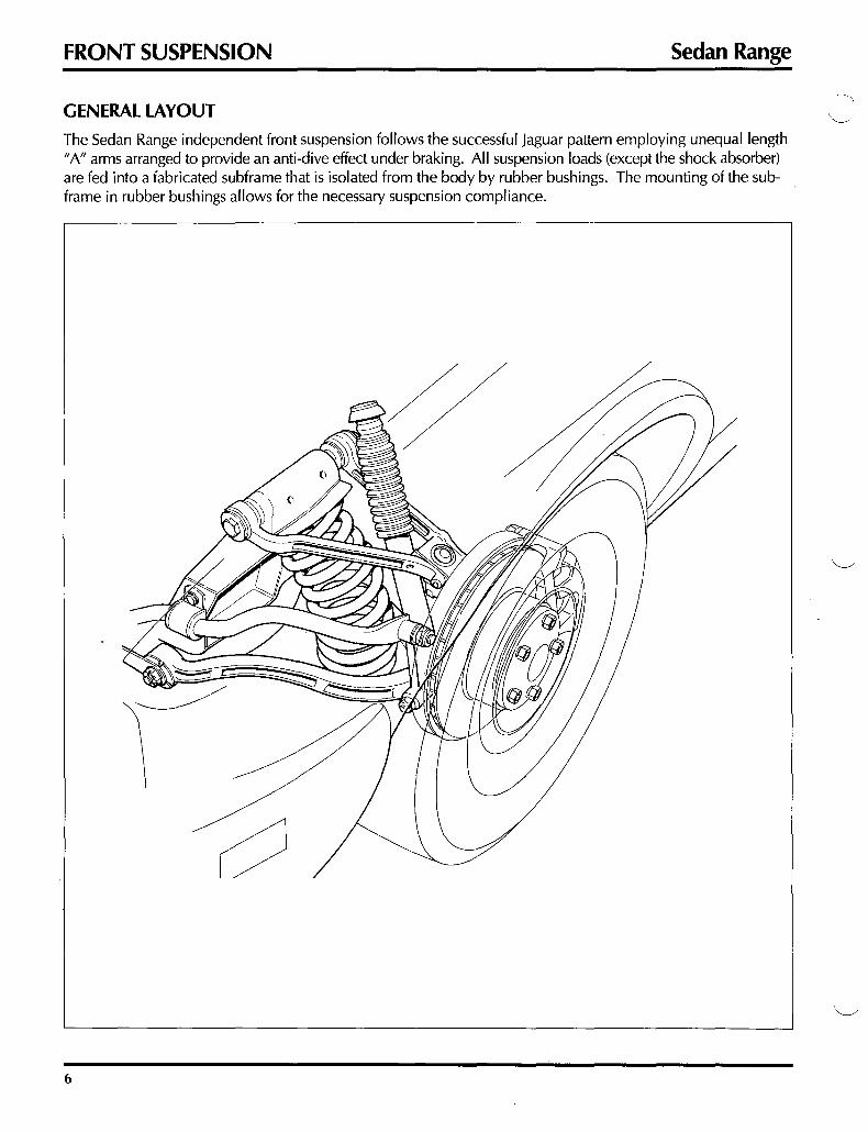
GENERAL LAYOUT
The Sedan Range independent front suspension follows the successful jaguar pattern employing unequal length "A" arms arranged to provide an anti-dive effect under braking. All suspension loads (except the shock absorber) are fed into a fabricated subframe that is isolated from the body by rubber bushings. The mounting of the subframe in rubber bushings allows for the necessary suspension compliance.
6

Sedan Range FRONT SUSPENSION
SUB FRAME
In the Sedan Range, the subframe is designed with the pitch control arms facing rearward. The front mounting bushings are "vee" shaped and incorporate steel safety straps. The subframe is foam-filled to provide rigidity, corrosion protection and noise insulation.
FORWARD
COMPONENTS "A" arms Both "A" arms are two-piece steel forgings. The upper arm incorporates shims at the ball joint for caster adjustment.
·-----0 '(/) REAR BUSHING
Hub Carrier and Ball Joints The forged-steel hub carrier has a pressed-fit stub axle and is retained by non adjustable sealed ball joints.
Springs and Shock Absorbers The road springs are color-coded and are installed with matching packings. The shock absorbers incorporate rebound stops for the suspension.
7

FRONT SUSPENSION XJS Range
GENERAL LAYOUT
The XJS independent front suspension has a design similar to that of the XJ6 and Sedan Range. Unequal length "A" arms provide an anti-dive effect under braking. All suspension loads (except the shock absorber) are fed into a fabricated subframe that is isolated from the body by rubber bushings. The mounting of the subframe in rubber bushings allows for the necessary suspension compliance.
8
XJS Range FRONT SUSPENSION
SUB FRAME
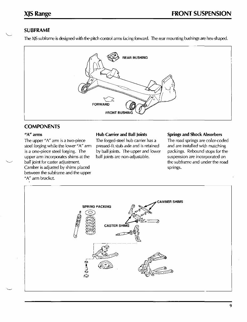
The XJS subframe is designed with the pitch control arms facing forward. The rear mounting bushings are hex-shaped.
~ REAR BUSHING
~ FORWARD
COMPONENTS 11A" arms The upper "A" arm is a two-piece steel forging while the lower "A" arm is a one-piece steel forging. The upper arm incorporates shims at the ball joint for caster adjustment. Camber is adjusted by shims placed between the subframe and the upper "A" arm bracket.
FRONT BUSHING
Hub Carrier and Ball Joints The forged-steel hub carrier has a pressed-fit stub axle and is retained by ball joints. The upper and lower ball joints are non-adjustable.
SPRING PACKING
@)
I
Springs and Shock Absorbers The road springs are color-coded and are installed with matching packings. Rebound stops for the suspension are incorporated on the subframe and under the road springs.
9

REAR SUSPENSION Sedan Range
GENERAL LAYOUT
The Sedan Range independent rear suspension is a basic two-link system with the drive shaft acting as the upper control arm. Isolation is provided by the use of a subframe assembly made up of several elements. The rugged construction of the lower control arm and the method of attachment eliminates the need for a radius arm to absorb fore and aft loads from the road wheel. Single coil/shock units attach between the lower control arm and body structure. The disc brake assemblies are mounted outboard and the wheel hubs are supported by aluminum hub carriers. All Sedan Range vehicles except the Xj6 4.0 employ ride leveling coil/shock units. This system is detailed in POWER HYDRAULICS.
10
RIDE LEVELING COIL I SHOCK UNIT

Sedan Range REAR SUSPENSION
SUBFRAME AND COMPLIANT SYSTEM
The Sedan Range subframe is made up of a cross-member and a wide mounting bracket. Additional support and attachment to the body are provided by struts and links.
Fore and aft compliance (movement) is provided by the pendulum bracket at the front of the final drive unit and the cross-tie at the rear of the final drive unit. This compliant system attaches to the axle through bushings and uses axle mass to dampen road noise.
BUSHING Q)
PENDULUM BRACKET LOWER CONTROL ARM
CAMBER ADJUSTMENT Rear wheel camber adjustment is provided by spacers of varying thicknesses placed between the drive shaft inner universal joint flange and the final drive output shaft flange. Consult the parts manual for spacer availability.
LEFT
PI@ CAMBER SPACERS
~ RIGHT
11

REAR SUSPENSION XJS Range
GENERAL LAYOUT
The XJS independent rear suspension is also a two-link design with the drive shaft acting as the upper link. The complete assembly, except for the radius arms, is mounted in a fabricated subframe that connects to the body. The built-up lower control arm incorporates the lower pivots for the dual coil shock units. Radius arms connect to the lower control arms and assist in absorbing fore and aft loads. The disc brake assemblies are mounted inboard, thereby reducing unsprung weight. The wheel hubs are supported by aluminum hub carriers.
12

XJS Range REAR SUSPENSION
COMPONENTS
The 4 subframe-mounting rubber bushings and the two forward radius-arm rubber bushings provide isolation from the body and the necessary suspension compliance. The built-up lower control arm connects to the final drive and subframe through a bracket on the inside and to the hub carrier at the outside. These pivot points are precision machined and employ both needle bearings and taper roller bearings requiring periodic lubrication.
~BUSHING
CAMBER ADJUSTMENT
Rear wheel camber adjustment is provided by shims of varying thicknesses placed between the drive shaft inner universal joint flange and the brake disc. Consult the parts manual for spacer availability.
13

ALIGNMENT Alignment Angles
CASTER
Caster is the forward or rearward inclination of the vertical steering axis in reference to a vertical line through the center of the wheel. This angle is measured in degrees.
Positive caster Caster is considered positive when the top of the steering axis is inclined rearward.
1/
¢J !I FORWARD
POSITIVE
Caster benefits
Negative caster Caster is considered negative when the top of the steering axis is inclined forward.
-\I
¢J l FORWARD
NEGATIVE
Zero caster Caster is zero when the steering axis is vertical.
'
I
¢J ! '
FORWARD
ZERO
Positive caster is normally specified in automotive application to provide directional stability and steering return ability.
FORWARD
POSITIVE CASTER
14
\----../

Alignment Angles ALIGNMENT
Caster problems Excessive positive caster can cause hard steering, road shock and shimmy. Too little positive caster, or negative caster, reduces directional stability and return ability.
Caster errors Caster error from side-to-side can cause a "pull" to one side. The vehicle will usually steer to the side with the least amount of positive caster.
. I I I i / ' '
II ''
I
15

ALIGNMENT Alignment Angles
CAMBER Camber is the inward or outward inclination of the wheel vertical axis in reference to a vertical line at the center of the wheel where it contacts the road. This angle is measured in degrees.
Positive camber Camber is considered positive when the top of the wheel is inclined outward.
+ ' '
,,
a==::#) I/ ,,
POSITIVE
Camber benefits
Negative camber Camber is considered negative when the top of the wheel is inclined inward.
-I I
''
II "
NEGATIVE
Zero camber Camber is zero when the wheel is vertical.
l '
I '
~ I '
I ZERO
A cambered wheel does not roll straight ahead. A wheel with positive camber will roll away from the center of the vehicle; a wheel with negative camber will roll toward the center of the vehicle. Front positive camber is normally specified in automotive application to provide directional stability and isolate road forces.
+ -' '
1/ I I
''
II "
POSITIVE NEGATIVE
16
~

Alignment Angles ALIGNMENT
Camber problems Excessive positive camber can cause scuffing on the outside of the tire tread. Excessive negative camber can cause scuffing on the inside of the tire tread.
ll Ll ' '
n ' '
1/ \ I
db ~ 1/ \I
~ 1
Camber errors Camber error from side-to-side can cause a "pull" to one side. The vehicle will usually steer to the side with the greater positive camber.
I ll '
,;
I 1/ '
db ~ I 1/ ' ,, q I
'
17

ALIGNMENT Alignment Angles
TOE AND RELATED ANGLES
Toe can be defined as the difference in distance measured across the front and across the rear of the wheels on the same axle. Toe is specified to achieve near zero toe during most driving conditions.
Toe-in Toe-in indicates that the front of the wheels are closer together than the rear of the wheels.
Toe-out Toe-otJt indicates that the front of the wheels are further apart than the rear of the wheels.
18

Alignment Angles ALIGNMENT
Zero toe Zero toe indicates that the front of the wheels are parallel to each other.
Individual toe Individual toe is the difference in distance measured from the vehicle centerline.
r --
19

ALIGNMENT
TOE AND RELATED ANGLES (continued)
Toe problems
Alignment Angles
Excessive toe-in can increase the amount of scuffing on the outside of the tire tread. Excessive toe-out can increase the amount of scuffing on the inside of the tire tread.
20

Alignment Angles ALIGNMENT
Rear Toe Rear toe is defined and measured the same as front wheel toe.
THRUST AXIS Thrust axis is the drive angle of the rear wheels and should fall on the center line of the vehicle. The angles on either side of the thrust axis are always equal regardless of the individual wheel angles.
When the thrust axis is not centered, the vehicle will tend to travel in a circle, requiring the driver to turn the steering wheel in order to steer straight ahead.
THRUST AXIS
21

ALIGNMENT
THRUST AXIS (continued)
On center With all suspension components and chassis dimensions within specification, the thrust axis will fall on the center line of the vehicle, providing normal handling, tracking and tire wear.
22
Damage offset If the chassis has been damaged causing displacement of the rear suspension unit, the thrust axis will be offset to one side.
THRUST AXIS
ON CENTER
_ THRUST AXIS --------
DAMAGE OFFSET
UNEQUAL TOE OFFSET
Alignment Angles
Unequal toe offset Unequal rear wheel toe will also offset the thrust axis. The example shows the left rear wheel toed-out creating an offset to the left.

Alignment Angles
OTHER ALIGNMENT ANGLES
Toe-out-on-turns Toe-out-on-turns is the differential angle between the inner and outer front wheels in a turn. Toe-out-onturns allows the wheels to travel in different diameter circles when the vehicle is turning.
Steering axis inclination Steering axis inclination is the angle formed by a line drawn through the steering axis and vertical.
TOE-OUT-ON-TURNS
I '
\ I
o::::::::ttdn ' '
o:==:::OI \ i
STEERING AXIS INCLINATION
SETBACK
ALIGNMENT
Set-back Set-back is the distance fore or aft of one front wheel to the other caused by chassis or suspension component damage.
23

ALIGNMENT Alignment Preparation
CHECK LIST FOR VEHICLE PREPARATION
Before proceeding with suspension alignment, the following must be carefully checked and rectified as necessary:
• Suspension components - wear and damage • Rubber bushings - wear
• Ball joints- wear • Shock absorbers- wear; leakage
• Steering tie rod ends - wear • Wheel bearings- wear; adjustment
• Steering gaiters and ball joint boots - damage • Wheel rims- condition
• Tires- inflation pressure; balance; wear patterns; tread depth; correct specification
CURB HEIGHT (VEHICLE LADEN)
CURB HEIGHT: SEDAN RANGE
CURB HEIGHT: XJS RANGE
= I
6 in. (min.) 7'/, in. ± 'I• in.
24

Alignment Preparation ALIGNMENT
CURB HEIGHT
Correct front and rear curb height is essential to good road holding, handling and ride. Because the suspension undergoes minor geometry changes as it moves through its range of travel, an incorrect curb height will result in incorrect suspension geometry for a specific vehicle load.
Curb height is checked with the vehicle in the "curb" condition on sliding wheel plates and on a level surface. Curb condition means that the vehicle has correct wheel and tire specification, correct tire pressure, full fuel, all fluid levels normal, and only the spare wheel and tools in the trunk. Be sure to "settle" the suspension by pressing down on the front and rear bumpers and gently releasing.
Curb Height Adjustment: All Models Adjustment to front and rear curb height is made by spring replacement.
CENTRALIZED STEERING
During alignment checks, the steering must be centralized to allow accurate measurement. An alignment pin (Sedan Range: tool JD 120; XJS Range: tool JD 117) is inserted into the rack to maintain the centralized position.
SEDAN RANGE XJSRANGE
25

ALIGNMENT Alignment Preparation
RIDE HEIGHT CONDITION
The wheel alignment of Jaguar vehicles is checked in the "ride height" condition. The ride height condition is achieved through the use of special tools to compress the suspension, simulating a partially loaded vehicle.
Ride Height Condition: Sedan Range The ride height condition for Sedan Range vehicles is specified as follows: the rear drive shafts are horizontal and the front suspension subframe is at a ride height of 6 in. to the underside.
With the vehicle resting on sliding wheel plates, tool JD 145 is installed at the rear with the large hook located around the drive shaft. After careful compression of the rear suspension, the small or upper hook is then attached to the top of the rebound stop. Next, tool JD 133 is used to compress the front suspension until the measurement between the wheel plates and the bottom of the subframe is 6 in. on both sides.
26

Alignment Preparation ALIGNMENT
Ride Height Condition: XJS Range The XJS ride height condition is achieved simply by the installation of two sets of special tools.
With the vehicle resting on sliding wheel plates, tool JD 25B is installed at the rear with the hook located in the hole in the subframe bushing plate. After careful compression of the rear suspension, the lower loop is then fitted over the lower control arm pivot nut. Next, tool JAG 1505 is placed between the upper "A" arm and the subframe bump stop as the front suspension is compressed.
ALIGNMENT SPECIFICATIONS Sed~m Range 1988 - 92 Model Year
Front Suspension
Toe Parallel to 1/16 in. Toe In Caster 3.5-4.5° Positive
(0.5° maximum variation side to side) Camber 0-0.5° Negative
Rear Suspension
Toe Camber
Parallel to 1/16 in. Toe In 0.5°-1° Negative
SUB FRAME
JAG 1505
XJS Range: 1982 - 92 Model Year Front Suspension
Toe Caster Camber
Rear Suspension
Toe Camber
Parallel to 1/8 in. Toe In 3.25°- 3.75° Positive
0.25°-0.75° Negative
Parallel to 1/32 in. Toe In 0.5°- 1 ° Negative
27

POWER HYDRAULICS Sedan Range
SYSTEM OVERVIEW Sedan Range vehicles use a central engine-driven power hydraulic system. In model years 1988 and 89, this system supplies hydraulic pressure for rear suspension ride leveling and brake power boost. In model years 1990 ON (except Xj6), the system supplies hydraulic pressure for the rear suspension ride leveling only. The basic design and operation of the central components of the system (pump and valve block) remain the same regardless of the model year.
1988- 89 MODEL YEARS
1990 ON MODEL YEARS
POWER STEERING
/ 1988 - 89 Model Years The power hydraulic system provides brake system power boost and rear suspension ride leveling. The power hydraulic system is completely separate from the brake hydraulic system. The two systems use different hydraulic fluid: Hydraulic System Mineral Oil (HSMO) in the power hydraulic system; DOT 4 brake fluid in the braking system.
Hydraulic Pressure Hydraulic pressure is supplied independent of engine speed, load or temperature. The reservoir supplies oil to the engine-driven pump, which in turn delivers high pressure oil to the valve block. The valve block has three functions using solenoid activated valves: brake boost charge, rear suspension up and rear suspension down.
28

Sedan Range POWER HYDRAULICS
Brake Power Boost The brake boost portion of the system incorporates an accumulator. Charging of the accumulator takes priority over ride leveling to ensure that a reserve capacity of pressurized hydraulic oil exists continually. The system has a reserve capacity to provide fully assisted brake applications. Two pressure switches are incorporated into the accumulator assembly. The charge switch activates the valve block charge valve. The low pressure warning switch provides a low pressure warning signal to the VCM (vehicle condition monitor) and disables the operation of the up solenoid until a minimum pressure is re-established in the accumulator.
Rear Suspension Ride Leveling The rear suspension ride leveling portion of the system operates automatically to maintain a minimum ride height. The ride leveling circuit makes trim adjustments to compensate for extreme load (weight) changes over the rear axle. A 20-second delay in the ride height sensor solenoid valve signals prevents the system from compensating for minor load changes, or for cornering loads and loads imposed by undulating road conditions.
1988- 89 MODEL YEARS
VALVE BLOCK
BOOST CYLINDER
CHARGE SWITCH; LOW PRESSURE
WARNING SWITCH
~----------..... ACCUMULATOR
ASSEMBLY
RIDE LEVELING STRUT
ACCUMULATOR VESSEL
NON-RETURN VALVE
RIDE LEVELING STRUT
A CAUTION: THE RIDE LEVELING SYSTEM WILL ALLOW THE VEHICLE TO BE OVERLOADED WITHOUT A PERCEPTIBLE CHANGE IN TRIM HEIGHT. ENSURE THAT THE SPECIFIED VEHICLE GROSS WEIGHT IS NOT EXCEEDED WHEN LOADING.
29

POWER HYDRAULICS
SYSTEM OVERVIEW (continued)
1990 ON Model Years (except XJ6)
Sedan Range
The Sedan Range vehicles with ride leveling use the central power hydraulic system to provide ride leveling only. This system shares its reservoir with the power steering system and both use Hydraulic System Mineral Oil (HSMO).
Vehicles up to VIN 653345 The valve block charge port to the previous brake boost accumulator is blocked off. The charge and up valves operate simultaneously to pressurize the ride leveling struts.
Vehicles VIN 653345 ON The valve block body remains the same with the charge port to the previous brake boost accumulator blocked off. Only the charge and down valves are installed. The up valve is replaced by a blanking plug.
30
1990 ON MODEL YEARS
VALVE BLOCK
NOTE: UP VALVE DELETED VIN 653345 ON
RIDE LEVELING STRUT
RIDE LEVELING STRUT
A CAUTION: THE RIDE LEVELING SYSTEM WILL ALLOW THE VEHICLE TO BE OVERLOADED WITHOUT A PERCEPTIBLE CHANGE IN TRIM HEIGHT. ENSURE THAT THE SPECIFIED VEHICLE GROSS WEIGHT IS NOT EXCEEDED WHEN LOADING.

Sedan Range POWER HYDRAULICS
VALVE BLOCK
1988 - 89 Model Years
The operation of the three valve block solenoid activated valves is controlled by the charge switch and the ride height sensor. The charge valve is normally open and the up and down valves are normally closed. The charge valve is activated by both the charge switch and the ride height sensor. The up valve is activated by the ride height sensor via the suspension relay. The down valve is activated directly by the ride height sensor. Refer to the wiring diagram on page 34.
1990 ON Model Years (vehicles up to VIN 653345)
The operation of the three valve block solenoid activated valves is controlled by the ride height sensor only. Both the charge and up valve solenoids are activated by the ride height sensor via the suspension relay. The down valve solenoid is activated directly by the ride height sensor. Refer to the wiring diagram on page 35.
Vehicles VIN 653345 ON
The up valve is deleted and replaced by a blanking plug. The operation of the charge and down valves remains the same as described above (1990 ON Model Years).
NOTE: UP VALVE DELETED VIN 653345 ON
VALVE BLOCK THEORETICAL DIAGRAM
NOTE: UP VALVE
DELETED VIN 653345 ON
PUMP
CHARGE
PRESSURE RELIEF VALVE
UP
RETURN TO RESERVOIR
D~ PRESSURE 0 REUEFVALVE
VALVE BLOCK
NON-RETURN /VALVE
ACCUMULATOR RIDE LEVEUNG
TRAPPED LINE PRESSURE VALVE
DOWN
31

POWER HYDRAULICS Sedan Range
VALVE BLOCK (continued)
No Charge I No Ride Leveling Operation When there is no call for accumulator charge pressure or ride leveling pressure, the charge valve is open, directing oil flow back to the reservoir. The up and down valves are closed to the ride leveling circuit.
CHARGE
PUMP 1r
NOTE: UP VALVE DELETED VIN 653345 ON
RETURN TO RESERVOIR
VALVE BLOCK
TRAPPED LINE PRESSURE VALVE
NON·RETURN /VALVE
ACCUMULATOR RIDE LEVELING
Accumulator Charge Operation (1988 - 89 MY only)
When the charge solenoid is activated, it closes the charge valve. Pressurized oil is applied to the brake boost circuit to recharge the accumulator. The pressure relief valve in the valve block protects the system from overpressurization.
32
CHARGE
-----PUMP 1r
NOTE: UP VALVE DELETED VIN 653345 ON
UP
RETURN TO RESERVOIR
DOWN
VALVE BLOCK
ACCUMULATOR RIDE LEVELING

Sedan Range POWER HYDRAULICS
Ride level Up Operation When ride leveling up pressure is required, the charge and up valve solenoids are activated to close the charge valve and open the up valve (vehicles up to VIN 653345). In vehicles VIN 653345 ON, the charge valve solenoid is activated to close the charge valve. Pressurized oil is directed to the ride leveling circuit to raise the rear of the vehicle. Pressurized oil is also applied to the brake boost circuit (1988- 89 MY vehicles). When the ride leveling compensation is achieved, the up valve closes and the charge valve opens directing oil from the pump to the reservoir.
The non-return valve under the up valve (or blanking plug) prevents return flow from the rear suspension if the charge pressure drops below the rear suspension pressure. The pressure relief valve prevents over-pressurization in the event of a gross overloading of the vehicle.
CHARGE __......_
PUMP ..
NOTE: UP VALVE DELETED VIN 653345 ON
UP
Ride level Down Operation
RETURN TO RESERVOIR
DOWN
VALVE BLOCK
ACCUMULATOR RIDE LEVELING
When ride leveling down is required, the down valve solenoid is activated to open the down valve allowing oil return to the reservoir to lower the rear of the vehicle. The trapped line pressure valve located within the down valve maintains a minimum pressure in the rear suspension.
CHARGE
PUMP ..
NOTE: UP VALVE DELETED VIN 653345 ON
UP
RETURN TO RESERVOIR
DOWN
VALVE BLOCK
ACCUMULATOR RIDE LEVELING
33

w "'"
:
ws
~
ws
r\ w
s w
s <J
~o"JJ~~Nst~~:~HED
,-------f---
WS
~ N
~
WS
l
(RE
FE
R T
O E
LEC
TR
ICA
L G
UID
E)
• I\
A
A~
--
v v
v
y
HA
ZA
RD
WA
RN
ING
-a
- 1BK
I I
--··
)-_
__
Y
LO
-~
~ ~ "~
~'
l R
ELA
Y
WA
RN
ING
SW
ITC
H
LCS
U
P
~,~YB _
_ ~--~YB,~lBK
CH
AR
GE
SW
ITC
H
YN
TE
ST
PIN
<!
LG ~
ws
YN
@
ri
'\1
1
·: Y
U ~
:~ ~-
:~ )-
Loow
N
• ~'' "'~
l w
,..
"rL----
........1
N
U
'>,Q
N
U
NU
<J
~~;.J
~~~UPP
LY 31
RID
E H
EIG
HT
VA
LV
E B
LO
CK
<m~"""rn"'~~'
i S
EN
SO
R
PO
WE
R H
YD
RA
UL
ICS
S
ED
AN
RA
NG
E 1
98
8-
89 M
OD
EL
YE
AR
S
( (
(
~ ..,., ;c
:I:
-(
0 ~ c r- n
trJ [ ~ ~ ~ ~

w
Ill
( (
ws
ws
ws
ws
-<J
I I
: W
S
ws
IGN
ITIO
N S
WIT
CH
ED
P
OW
ER
SU
PP
LY
N
~
ws
y
~
~0 'l
I
I I
I s:
I Y
LG
-=
CH
AR
GE
YN
(RE
FE
R T
O E
LEC
TR
ICA
L G
UID
E)
TE
ST
PIN
{!
LG
:>
----1
W
S
YN
('
@
rl'\
-11
·:
YU
~
:~ ~
:~ D
----
--
1 D
OW
N
• N
K
N
, .. ~
I ·~
w ~
" f-
1 N
K
NK
C
• N
K
'-<
j ~~-::J
~~~UPPLY
1 LR
-ID_E
_H_E
_I_G_
H_T..
.J (R
EF
ER
TO
ELE
CT
RIC
AL
GU
IDE
) :
SE
NS
OR
VA
LV
E B
LO
CK
NO
TE
: U
P V
AL
VE
DE
LET
ED
V
IN 6
5334
5 O
N
PO
WE
R H
YD
RA
UL
ICS
S
ED
AN
RA
NG
E 1
990
ON
MO
DE
L Y
EA
RS
-=
[ ~ ~ ~ ~ l"n
=='.::~ :I:
-< c $: c:
r- n
fJ')

POWER HYDRAULICS
SYSTEM OPERATION: 1988- 89 MODEL YEARS
Brake Boost: CHARGE
Sedan Range
System charging occurs if the accumulator pressure falls below 83 bar. At 83 bar, the charge switch closes, completing the charge valve solenoid circuit to ground and closing the charge valve. Pressurized hydraulic oil is applied to the boost circuit as described earlier. The system continues to charge until the accumulator pressure reaches 1 00 bar, at which time the charge switch opens directing pressurized oil from the pump to the reservoir.
If the accumulator pressure falls below 54 bar (at engine start or during operation), the low pressure warning switch opens, with two results: the VCM low pressure warning activates and the suspension relay ground circuit from pin 87 is interrupted. Interrupting the relay ground circuit disables the up valve circuit thereby prioritizing brake boost. Thelow pressure warning switch closes when the accumulator pressure reaches 69 bar, reversing the above conditions.
Ride Leveling: UP COMPENSATION If the accumulator pressure falls below 54 bar, brake boost is prioritized as described above. Once the low pressure switch opens at 54 bar, no up compensation occurs until the accumulator pressure reaches 69 bar and the switch closes. If the accumulator pressure is 54 bar or above, or 69 bar or above (as applicable), up compensation can occur.
Note: Up compensation will not occur until the vehicle load causes the rear suspension to lower approximately 2 1/4 inches.
When the ride height sensor detects a requirement for up compensation, a 20-second delay occurs before the sensor completes the suspension relay solenoid circuit to activate the relay. When activated, the relay completes the charge and up valve solenoid circuits simultaneously. The charge valve closes and the up valve opens applying hydraulic pressure to the rear suspension struts. Additionally, hydraulic pressure is applied to the accumulator. The non-return valve in the accumulator maintains pressure in the brake boost circuit. As the normal ride height is reached, the sensor switches off the suspension relay, opening the charge valve and closing the up valve. Hydraulic pressure from the pump is returned to the reservoir.
The non-return valve under the up valve prevents return flow from the rear suspension if the pump pressure drops below the rear suspension pressure while the up valve is open.
The valve block pressure relief valve allows return to the reservoir at 120- 155 bar preventing over-pressurization in the event of gross overloading of the vehicle.
The 20-second sensor output delay prevents the system from reacting to suspension loads imposed by cornering or bumpy roads.
Ride Leveling: DOWN COMPENSATION When the ride height sensor detects a requirement for down compensation, a 20-second delay occurs before the sensor completes the down valve solenoid circuit to open the down valve. When open, the down valve allows oil to return to the reservoir, thereby lowering the rear of the vehicle. As the normal ride height is reached, the sensor switches off the down solenoid, closing the down valve.
The trapped line pressure valve within the down valve maintains a minimum pressure of 28 bar in the ride leveling circuit. This "trapped line pressure" (minimum pressure) prevents damage to the suspension struts caused by too little hydraulic pressure. A revised ride height sensor incorporating a momentary pressure cycle was introduced at VIN 617978. Each time the engine is started, the ride leveling circuit is pressurized for a few seconds (after a 40-second delay), preventing the gradual loss of "trapped line pressure". This action ensures that adequate hydraulic pressure is maintained in the ride leveling struts. Refer to page 15. If the ride height sensor outputs a down signal, the 28 bar minimum pressure prevents further suspension down travel and no down travel is detected. The sensor cancels the output after approximately 5 minutes.
36

·\____.
Sedan Range POWER HYDRAULICS
The 20-second sensor output delay prevents the system from reacting to suspension loads imposed by cornering or bumpy roads.
Brake Boost: OPERATION Accumulator pressure is applied to the brake boost cylinder at all times and produces a pedal return force of 20 pounds to move the boost piston to the full return position.
When the brakes are applied, the pressurized oil from the accumulator is fed to the servo chamber, providing pedal assist. A reaction disc within the boost cylinder ensures that the degree of boost is proportional to the application effort from the driver (up to the limit of boost).
When the brakes are released, the servo hydraulic pressure is vented to the reservoir. The hydraulic oil returns to the reservoir. The boost piston returns to the full return position.
37

POWER HYDRAULICS Sedan Range
SYSTEM OPERATION: 1990 ON MODEL YEARS Ride Leveling: UP COMPENSATION (Vehicles up to VIN 653345)
Note: Up compensation will not occur until the vehicle load causes the rear suspension to lower approximately 2 1/4 inches.
When the ride height sensor detects a requirement for up compensation, a 20-second delay occurs before the sensor completes the suspension relay solenoid circuit to activate the relay. When activated, the relay completes the charge and up valve solenoid circuits simultaneously. The charge valve closes and the up valve opens, applying hydraulic pressure to the rear suspension struts. As the normal ride height is reached, the sensor switches off the suspension relay opening the charge valve and closing the up valve. Hydraulic pressure from the pump is returned to the reservoir.
The non-return valve under the up valve prevents return flow from the rear suspens.on if the pump pressure drops below the rear suspension pressure.
The valve block pressure relief valve allows return to the reservoir at 120- 155 bar, preventing over-pressurization in the event of gross overloading of the vehicle.
The 20-second sensor output delay prevents the system from reacting to suspension loads imposed by cornering or bumpy roads.
Ride Leveling: UP COMPENSATION (Vehicles VIN 653345 ON)
Note: Up compensation will not occur until the vehicle load causes the rear suspension to lower approximately 2 1/4 inches.
When the ride height sensor detects a requirement for up compensation, a 20-second delay occurs before the sensor completes the suspension relay solenoid circuit to activate the relay. When activated, the relay completes the charge valve solenoid circuit. The charge valve closes, applying hydraulic pressure to the rear suspension \____./ struts. As the normal ride height is reached, the sensor switches off the suspension relay opening the charge valve. Hydraulic pressure from the pump is returned to the reservoir.
The non-return valve under the up valve blanking plug prevents return flow from the rear suspension.
The valve block pressure relief valve allows return to the reservoir at 120- 155 bar preventing over-pressurization in the event of gross overloading of the vehicle.
The 20-second sensor output delay prevents the system from reacting to suspension loads imposed by cornering or bumpy roads.
Ride Leveling: DOWN COMPENSATION When the ride height sensor detects a requirement for down compensation, a 20-second delay occurs before the sensor completes the down valve solenoid circuit to open the down valve. When open, the down valve allows oil to return to the reservoir, thereby lowering the rear of the vehicle. As the normal ride height is reached, the sensor switches off the down solenoid, closing the down valve.
The trapped line pressure valve within the down valve maintains a minimum pressure of 28 bar in the ride leveling circuit. This "trapped line pressure" (minimum pressure) prevents damage to the suspension struts caused by too little hydraulic pressure. A revised ride height sensor incorporating a momentary pressure cycle was introduced at VIN 617978. Each time the engine is started, the ride leveling circuit is pressurized for a few seconds (after a 40-second delay), preventing the gradual loss of "trapped line pressure". This action ensures that adequate hydraulic pressure is maintained in the ride leveling struts. If the ride height sensor outputs a down signal, the 28 bar minimum pressure prevents further suspension down travel and no down travel is detected. The sensor cancels the output after approximately 5 minutes.
The 20-second sensor output delay prevents the system from reacting to suspension loads imposed by cornering or bumpy roads. ·~
38

Sedan Range
COMPONENTS
Reservoir (1988 - 89 MY)
The reservoir incorporates a visual level indicator plus a level sensor to signal the VCM (vehicle condition monitor). The reservoir can only be filled with HSMO from a container with a unique connector.
Pump The three cylinder radial hydraulic pump turns at 3/ 4
engine speed and is driven directly by the engine from the intermediate shaft drive pad. A coupling is used to connect the pump to the drive.
PUMP OUTPUT
0.153 gallons (0.7 litres) per minute @ 600 rpm (pump speed)
POWER HYDRAULICS
Reservoir (1990 MY ON)
The reservoir serves as the reservoir for the both the power hydraulic and power steering systems. Both systems use HSMO. The fill cap incorporates a dip stick for checking the fill level.
NOTE: UP VALVE DELETED YIN 653345 ON
Valve Block The valve block contains the solenoid activated valves that are used to direct oil as necessary. Additionally, the valve block contains a pressure relief valve, a nonreturn valve and a trapped line pressure valve. The function of all the components is described previously.
PRESSURE RELIEF VALVE SPECIFICATION
Early valve Later valve
120-140 bar 135-155 bar
TRAPPED LINE PRESSURE VALVE SPECIFICATION
28-45 bar
39

POWER HYDRAULICS
COMPONENTS (continued)
CHARGE SWITCH; LOW PRESSURE
WARNING SWITCH
Accumulator (1988 - 89 MY)
The accumulator has a nitrogen charged chamber separated from the pressurized hydraulic oil by a diaphragm. The pressurized nitrogen stores system pressure and maintains boost pressure when the pump is inoperative or if a failure occurs. A non-return valve prevents return flow and maintains pressure on the accumulator side of the system. Two pressure switches are mounted on the accumulator base.
CHARGE SWITCH SPECIFICATION
OPEN (no system charge) CLOSE (system charge)
100 bar 83 bar
LOW PRESSURE WARNING SWITCH SPECIFICATION
OPEN (VCM warning on; UP disabled) 54 bar CLOSE (VCM warning off; UP enabled) 69 bar
Ride Height Sensor
The ride height sensor incorporates an LED (light emitting diode) height sensing mechanism and an electronic control module. The unit incorporates the logic necessary for providing the 20-second delay before activating the up or down solenoid valves. Later sensors incorporate a charge replenishment cycle.
40
Sedan Range
Brake Boost Cylinder (1988 - 89 MY)
The brake boost cylinder is activated by the brake pedal and converts hydraulic pressure supplied from the power hydraulic system into brake boost pressure. The degree of boost is proportional to the application effort from the driver.
Ride Leveling Strut
The ride leveling strut provision is incorporated into the strut units.

Sedan Range ANTI-LOCK BRAKING
GENERAL LAYOUT The BOSCH anti-lock braking system in the Xj6 3.6 eliminates wheel lock by modulating the hydraulic pressure applied to the individual brake calipers so that adhesion between the tire and the road is maintained under all driving conditions. A modulator is situated in the three brake hydraulic pressure lines- front left brake, front right brake and rear brakes. Each road wheel is equipped with a wheel speed sensor. The electronic control unit (ECU) receives continuous input from the four wheel speed sensors and controls the modulator action to provide anti-lock braking.
SEDAN RANGE 3.6
/ )
~ REARWHEEL .//SPEED SENSORS
41

ANTI-LOCK BRAKING Sedan Range 3.6
SYSTEM SELF-TESTS The ECU automatically performs self-tests and signals the instrument pack to display warnings on the vehicle condition monitor (VCM). Testing is performed in three stages:
• Initial tests
• Low Speed Tests
• Continuous Tests
Initial Tests Initial tests are performed as the ignition is switched to position II.
- Simulated wheel speed sensor signals are generated and the input circuits are checked for the correct response.
- The battery voltage is checked to ensure that it is greater than 1 0 volts.
- Wheel acceleration and deceleration levels are checked to ensure that they are set correctly.
If the initial tests are completed satisfactorily, the fail warning will cancel.
Low Speed Tests Low speed tests are performed the first time the vehicle speed reaches 3.6 mph after start-up.
Note: If the brakes are applied at 3.6 mph, the driver will feel the brake pedal move.
- The modulator valves are actuated and monitored to ensure that currents are flowing.
- The pump is activated and its operation verified by the voltage developed across its windings when it is switched off.
Low speed tests occur only on the first occasion that the test speed is detected and are reset when the ignition is switched off.
Continuous Tests Continuous tests are performed continuously while the vehicle is running.
42

"'" w
(
Ee
(
DIR
EC
TB
AT
TE
RY
[>
N
g U
R
PO
WE
R F
EE
D
RY
W
PU
S
TO
P L
IGH
TS
GY
<J
IGN
ITIO
N S
WIT
CH
ED
lo
PO
WE
R F
EE
D
•) U
G
1 A
LTE
RN
AT
OR
RB
--
----
rl-,
(\
RB
--
-L.t
-\..
_)
RW
--
----
rl-,
(\
RW
--
-L.t
-\..
_)
: =
o()
56D
Q
BR
AK
E L
IGH
T
SIM
UL
AT
ION
Y
B
RE
LA
Y
RIG
HT
FR
ON
T
WH
EE
L S
PE
ED
S
EN
SO
R
LE
FT
FR
ON
T
WH
EE
L S
PE
ED
S
EN
SO
R
RIG
HT
RE
AR
W
HE
EL
SP
EE
D
SE
NS
OR
DIR
EC
T B
AT
TE
RY
[>
P
OW
ER
FE
ED
sw
WK
<J
IG
NIT
ION
SW
ITC
HE
D
PO
WE
R F
EE
D
OV
ER
VO
LT
AG
E
-= R
EL
AY
PU
MP
RE
LAY
~
PU
MP
MO
TOR
RU
=
o()
LEF
T R
EA
R
WH
EE
L S
PE
ED
D
IRE
CT
BA
TTE
RY
I>
N
l ~
RU
S
EN
SO
R
PO
WE
R F
EE
D
yp
GW
I ~
0:========
==========
==========
==========
==========
====~~=---
----------
------~~~~
~~~~~~====
====~~
UO
H
AZ
AR
D W
AR
NIN
G
/ K
LG
YG
~C't--
__
___.
_ __
VA
LVE
RE
LAY
RIG
HT
FRO
NT
VA
LVE
P
W
RE
AR
VA
LVE
S
R
B
AN
TI-
LO
CK
BR
AK
INi
'11 ~~,&
~ E
CU
G
\
~ ~
AB
S
MO
DU
LA
TO
R
-= A
NT
I-L
OC
K B
RA
KIN
G
SE
DA
N R
AN
GE
3.6
(
Cl'l
~ S' ::::s
~
w ~ > z -1 - ~ ~ = s: ~ - z ~

ANTI-LOCK BRAKING Sedan Range 3.6
COMPONENTS Wheel Speed Sensors Each wheel speed sensor is made up of a magnetic sensor and a rotating 48-tooth reluctor. When the reluctor turns, it produces electrical pulsations that are fed to the ECU as individual wheel speed information.
FRONT
REAR
~---
44

Sedan Range 3.6 ANTI-LOCK BRAKING
Electronic Control Unit The ECU is a microprocessor that is programmed to provide anti-lock braking. The ECU compares inputs received from the wheel speed sensors and activates the modulator solenoid valves and return pump as necessary to prevent wheel lock.
Modulator Assembly The modulator assembly contains the three solenoid-activated valves situated in the brake pressure lines: left front, right front and rear brake hydraulic circuits. Two accumulators (one in each supply line from the master cylinder) store excess hydraulic fluid during a pressure drop associated with anti-lock operation. A pump recirculates return fluid from the calipers during anti-lock operation.
45

ANTI-LOCK BRAKING Sedan Range 3.6
SYSTEM OPERATION Anti-Lock Control When wheel lock is imminent, the ECU activates and controls the modulator in three stages. Depending on braking conditions, the ON -OFF three stage cycle occurs between two and eight times per second. The cycle will continue until the ECU senses that all wheel speed sensors are within a specified relative speed range.
First Stage: Pressure Hold The appropriate modulator solenoid valve closes off the supply port from the master cylinder preventing additional brake hydraulic pressure from being applied to the decelerating wheel (wheels, rear) brake caliper.
46
WHEEL SPEED
SENSOR
ABS MODULATOR
ECU

Sedan Range 3.6 ANTI-LOCK BRAKING
Second Stage: Pressure Reduce· If the wheel continues to decelerate, the solenoid valve return port is opened, reducing the hydraulic pressure to the caliper and allowing the wheel to accelerate. When the return port is opened, the ECU activates the pump to recirculate the returned hydraulic fluid to the supply side of the accumulator.
WHEEL SPEED
SENSOR
MODULATOR VALVE
ABS MODULATOR
ECU
Third Stage: Pressure Increase (Normal Brake Operation) The solenoid valve is positioned to allow normal hydraulic flow to and from the brake caliper(s).
WHEEL SPEED
SENSOR
ABS MODULATOR
ECU
47

ANTI-LOCK BRAKING
GENERAL LAYOUT
SEDAN RANGE 4.0
Sedan Range 4.0 and XJS Range
FRONT WHEEL SPEED SENSORS
ECU
REAR WHEEL SPEED SENSORS
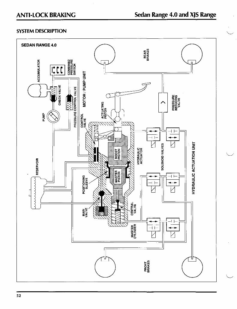
The TEVES brake system combines normal system operation, power boost and anti-lock braking. The system uses an independent electrically-driven motor pump unit to provide both boost pressure and brake application pressure. A common operating fluid, DOT 4 BRAKE FLUID, is used for both power boost and brake application.
In the TEVES system, three hydraulic circuits are used- one to each front wheel and one to the rear wheels. Depending on the mode of operation, the circuits operate differently:
Normal Operation The two front hydraulic circuits operate conventionally via the master cylinder, assisted by the hydraulic booster. The rear hydraulic circuit is operated continuously by the controlled pressure in the booster via the pressure reducing valve. Simply stated, during normal operation, the front hydraulic circuits are "static" and the rear circuit "dynamic".
Anti-Lock Operation When anti-lock control is required, the front hydraulic circuits also become "dynamic" as boost pressure replaces master cylinder pressure via the main valve. The four wheel speed sensors input to the ECU, which processes the information and modulates the three sets of solenoid valves in the valve block to control the pressure in the three circuits and prevent wheel lock. Because both rear wheels share a common circuit, a tendency for one wheel to lock will result in control of both wheels according to the need of the "locking" wheel.
The state of the anti-lock system is continuously monitored by the ECU. If a failure is identified, the ECU switches off the ABS system and signals the VCM. Full boosted braking to all wheels is maintained if the ECU switches off the ABS system. If a failure of the hydraulic boost portion of the system occurs, the brake system will function on the front wheels only, without boost pressure.
Fault Diagnostics The TEVES anti-lock braking system incorporates a system for assisting in diagnosis of intermittent faults. The ABS warning indicator blinks to show numeric codes that are cross-referenced to code charts in the Service Manual to identify the fault(s).
48

.r;.
I.e
(
FR
ON
T W
HE
EL
S
PE
ED
SE
NS
OR
S
(
PR
ES
SU
RE
R
ED
UC
ING
VA
LV
E
RE
AR
WH
EE
L
SP
EE
D S
EN
SO
RS
~
CJ)
::0
)>
z G') m
(
(I) a. ~ ::
l ~ ~ ~
b ~ c.. ~
(I) ~ ~ >
z ---1 -I r- ~ ,.::: =
~ ,.::: - z ~

ANTI-LOCK BRAKING Sedan Range 4.0 and XJS Range
GENERAL LAYOUT: SEDAN RANGE 4.0
SEDAN RANGE 4.0
In the Sedan Range, the motor pump unit, reservoir and hydraulic actuation unit are integrated on the brake pedal and accelerator housing. The motor pump unit contains the hydraulic pump, motor, accumulator and combined pressure switch. The hydraulic actuator incorporates many components including the solenoid valve block.
50

Sedan Range 4.0 and XJS Range
GENERAL LAYOUT: XJS RANGE
XJS RANGE
RESERVOIR
SOLENOID VALVE BLOCK
COMBINED PRESSURE SWITCH
ANTI-LOCK BRAKING
ACCUMULATOR
I
PUMP
In the XJS, the motor pump unit is located separately on the right side of the front bulkhead. The reservoir and the hydraulic actuation unit are integrated on the brake pedal and accelerator housing. The motor pump unit contains the hydraulic pump, motor, accumulator and combined pressure switch. The hydraulic actuator incorporates many components including the solenoid valve block.
51
~I
(
FR
ON
T
BR
AK
ES
RE
SE
RV
OIR
HY
DR
AU
LIC
AC
TU
AT
ION
UN
IT
(
I I
AC
CU
MU
LA
TO
R
···-
--.--
..---
'I
MO
TO
R I
PU
MP
UN
IT
PR
ES
SU
RE
R
ED
UC
ING
V
AL
VE
RE
AR
B
RA
KE
S
C/) m
c J>
z ::0
J>
z G) m
ol:>o
0
I
~ ~
rn
~ c rn
{I)
n ~ ~ a z
I
(
> z ...
.j -I r- ~ ~ =
s: ~ - z ~ Cl)
B.
~ ~ ~ ~
b ~ Q.
~
Cl)
S' ~ ~

·~.
Sedan Range 4.0 and XJS Range ANTI-LOCK BRAKING
SYSTEM DESCRIPTION Hydraulic Actuation Unit The hydraulic actuation unit contains the reservoir and the components used for pressure application, boost application and anti-lock valving.
Actuating piston The actuating piston transmits the motion from the brake pedal to the control valve and the boost piston.
Control valve The control valve opens and closes the high pressure line from the accumulator to the actuator hydraulic booster.
Hydraulic booster The boost piston is independent from the actuating piston and applies boost pressure on the master cylinder piston. Boost pressure is used to directly operate the rear brakes.
Master cylinder The master cylinder operates the front brakes only.
Main valve The solenoid-activated main valve is opened under anti-lock conditions to apply boost pressure directly to the master cylinder and the front brake circuits.
Central valve The central valve opens under anti-lock conditions to allow boost pressure to be applied directly to the front brakes.
Positioning sleeve The positioning sleeve is used during anti-lock operation to minimize brake pedal pulsations.
Solenoid valves The six solenoid valves direct hydraulic pressure and hydraulic return in the three brake circuits during anti-lock conditions. During normal operation, the valves are at rest, allowing conventional application.
Motor Pump Unit The motor pump unit supplies the system-operating hydraulic pressure.
Pump The pump is driven by an electric motor and is switched on and off to maintain a range of operating pressure.
Accumulator The accumulator stores the pump pressure and provides reserve for normal, anti-lock and pump failure operations. A check valve prevents pressure loss.
Pressure control valve The pressure control valve limits the maximum system pressure.
Combined pressure switch Two sets of contacts in the pressure-operated switch signal the ECU for activation of warnings and anti-lock shutdown. The other contacts switch the pump on and off. (The brake warning switch contacts close at 105 bar turning on the warning light. The pump switches on at 140 bar and off at 180 bar.)
Pressure Reducing Valve Since the rear brakes operate directly off boost pressure, a pressure-limiting device is necessary. The pressure reducing valve is located in the rear brake circuit and limits the pressure applied to the rear brakes. (A differential of 6 bar is maintained between the front and rear circuits.)
53

ANTI-LOCK BRAKING Sedan Range 4.0 and XJS Range
SYSTEM OPERATION
SEDAN RANGE 4.0
a: w
a: c 0 z 1- ::::i
a: <t > 0 ...J ()
> ::I a: a: :a: 1- w w ::I C/) 1-
C/) C/) () 0 C/)
w () 0 <t w a: <t co :a: a:
ID D ~
54

Sedan Range 4.0 and XJS Range ANTI-LOCK BRAKING
SYSTEM OPERATION: BRAKES NOT APPLIED Control Valve The control valve is open to the reservoir and closed to accumulator pressure from the motor pump unit.
Pump The pump is switched on or off as determined by system pressure.
Accumulator The accumulator stores boost pressure for use as soon as brakes are applied.
Boost Piston The boost piston is retracted.
Positioning Sleeve The positioning sleeve is at rest.
Master Cylinder The master cylinder is at rest.
Main Valve The main valve is switched off.
Equalized Hydraulic Pressure The hydraulic pressure is equalized throughout the system (except in the accumulator-to-control valve line).
55
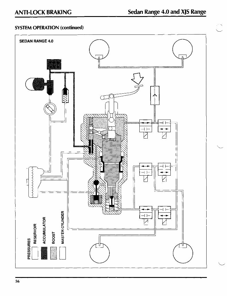
ANTI-LOCK BRAKING
SYSTEM OPERATION (continued)
56
SEDAN RANGE 4.0
a: 0 > a: w
en en w w a: a:
ID 1-m 0 0 Ill
.
.
a: w c z ::::i > (.)
a: w 1-m <t ==
D
Sedan Range 4.0 and XJS Range
-~--- ...........

Sedan Range 4.0 and XJS Range ANTI-LOCK BRAKING
SYSTEM OPERATION: BRAKES APPLIED- NORMAL OPERATION
Control Valve As the driver applies force to the brake pedal, the actuating piston moves forward. The lever mechanism moves the control valve forward, opening the port from the accumulator and closing the return port to the reservoir. Boost pressure is applied to the boost piston and the rear brakes.
Boost Piston The boost piston increases the pedal force acting on the master cylinder piston.
Main Valve The main valve remains at rest, connecting the master cylinder to the reservoir.
Central Valve As the master cylinder piston moves forward, the central valve closes and pressure is built up in the front brake circuits.
Positioning Sleeve The positioning sleeve moves forward with the boost piston. The displaced fluid returns to the reservoir through the main valve, which is at rest.
Pressure Reducing Valve Boost pressure is applied to the rear brakes through the pressure reducing valve.
Solenoid Valves All solenoid valves are at rest, allowing pressure application and preventing return to the reservoir.
Boost Pressure Control As the boost pressure increases, it acts between the boost piston and the actuating piston, \.____...- moving the actuating piston back, which moves the control valve to close the port from the accumulator. The
control valve closes the accumulator pressure port when the pedal force and boost force acting on the actuating piston equalize. The return port to the reservoir remains closed. The resulting pressure in the booster is proportional to the pedal force: low pedal force = low pressure, high pedal force= high pressure.
"Dynamic", "Static" During normal operation, boost pressure is applied directly to the rear brake circuit, thus the description "dynamic". The front brake master cylinder is supplied with reservoir gravity pressure only, thus the description "static".
57

ANTI-LOCK BRAKING
SYSTEM OPERATION (continued)
SEDAN RANGE 4.0
58
a: 0 > a: w
en en w w a: a:
~D
a: 0 ~ ...J ::I
== ::I () () <(
len 0 0 lXI
a: w c z ::i >()
a: w len <(
==
Sedan Range 4.0 and XJS Range
\"-..._ . ../

Sedan Range 4.0 and XJS Range ANTI-LOCK BRAKING
SYSTEM OPERATION: BRAKES APPLIED- ANTI-LOCK OPERATION
Main Valve When the ECU senses the need for ABS control, it activates the main switch, which moves the main valve, closing the reservoir feed line and applying boost pressure to the master cylinder circuit.
Central Valve The central valve is held open by the pressure, allowing boost pressure to be applied directly to the front brake circuits.
Positioning Sleeve The positioning sleeve is gradually moved to its rest position by the boost pressure. This action pushes back the boost piston, the actuating piston and the brake pedal, minimizing ABS pulsations transmitted to the brake pedal.
Solenoid Valves The solenoid valves are modulated by the ECU, as necessary, to prevent wheel lock.
11Dynamic", 11Dynamic" During ABS operation, both the front and rear brake circuits are "dynamic", as the front brakes are also operated directly by boost pressure.
59

ANTI-LOCK BRAKING Sedan Range 4.0 and XJS Range
SOLENOID VALVE OPERATION
A pair of solenoid valves for one control circuit is shown. During ABS operation, the ECU modulates the valves in three phases as necessary to prevent wheel lock. The three phases are repeated up to six times per second until wheel lock is eliminated.
Normal Operation During normal braking operation, the solenoid valves are not controlled by the ECU and no current is applied. The inlet valve is open and the outlet valve is closed, porting hydraulic pressure to the brake caliper circuits.
Phase Two: Pressure Reduce
HYDRAULIC PRESSURE
• RESERVOIR
If a wheel still has a tendency to lock with the pressure maintained, the ECU activates both valves, which prevents the application of hydraulic pressure and allows return to the reservoir, decreasing the pressure in the brake circuit.
60
Phase One: Pressure Hold
HYDRAULIC PRESSURE
1111.. BRAKE Ill"" CALIPERS
RESERVOIR
To maintain brake pressure, the ECU activates the inlet valve, which closes and prevents the application of additional hydraulic pressure. The outlet valve remains closed, preventing return to thsreservoir.
1111.. BRAKE Ill"" CALIPERS
RESERVOIR
Phase Three: Pressure Increase As the wheel accelerates, the ECU deactivates both valves, allowing hydraulic pressure to be applied to the brakes.
·~·

Sedan Range 4.0 and XJS Range ANTI-LOCK BRAKING
ELECTRICAL CIRCUITS
The two ABS electrical circuits are similar. The Sedan Range uses an additional ECU relay; the XJS (1990- 91 MY) uses a Brake Warning Light Inverter relay. The systems are switched on by the ignition switch via the ECU.
Electronic Control Unit The ECU processes information from the wheel speed sensors and the various switches for system operation, control and warnings.
Main Relay The main relay provides the power for system operation. The control circuit is switched by the ECU from an ignition ON signal.
Pump relay The pump relay provides remote pump switching. The control circuit is ignition-fed and is switched by the pump contacts in the combined pressure switch.
Reservoir: XJS The reservoir contains three fluid-level operated reed switches. Two "normally open" switches light the BRAKE FAILURE warning if the level drops too low. The third, "normally closed" switch signals the ECU if the level drops below the minimum level required for full ABS operation. In this case, the ECU switches off the front wheel ABS and lights the ABS warning.
Reservoir: Sedan Range 4.0 The reservoir contains two fluid-level operated reed switches. The "normally open" switch activates the VCM (vehicle condition monitor) BRAKE warning if the level drops too low. The "normally closed" switch signals the ECU if the level drops below the minimum level required for full ABS operation. In this case, the ECU switches off the front wheel ABS and activates the VCM ABS warning.
Combined Pressure Switch The combined pressure switch contains three pressure-operated switches. The two "normally open" switches clos~ when normal operating pressure is reached, switching off the pump and the BRAKE FAILURE warning. The third "normally closed" switch opens if the system pressure falls too low and signals the ECU which lights the ABS warning. XJS 1989 MY systems use a combined pressure switch with two "normally closed" switches and one "normally open" switch.
Main Switch The main switch activates the main valve on signal from the ECU.
Diagnostic Socket The diagnostic socket is provided for conducting system self-tests.
61

ANTI-LOCK BRAKING
BATTERY POWER SUPPLY
IN-LINE 30A
DIAGNOSTIC SOCKET
POWER GROUND 1
OUTLET VALVE, F!LEFT (OUT) 2
ECU RELAY (OliT) 3
RES. FULL SWITCH (OUT) 8
POWER GROUND 18
INPUT VALVE, FILEFT (IN) 20
OunET VALVE, F/RIGHT (IN) 21
DIAGNOSTIC SOCKET (OUT) 23
SHIELD 27
SHIELD 28
SHIELD 29
SHIELD 30
BRAKES APPLIED SWITCH (IN) 32
ECU RELAY (IN) 33
MAIN RELAY (IN) 34
OUTLET VALVE, REAR (IN) 36
INLET VALVE, F!RIGHT (IN) 38
MAIN VALVE (IN) 39
WHEEL SPO SENS, A/REAR (IN) 45
WHEEL SPO SEN$, UREAR (IN) 46
WHEEL SPD SENS, RIFRONT (IN) 47
WHEEL SPO SENS, LJFRONT (IN) 48
COMBINED PRESS. SWITCH (IN) 51
DIAGNOSTIC SOCKET (OUT) 52
IGNITION SWITCHED POWER 53
INLET VALVE, REAR (IN) 54
ANTI-LOCK BRAKING ECU
IGNITION SWITCHED POWER SUPPLY
CENTER FUSE PANEL
#83A
NO NP
NP RB NK B
B GY RY
1.,, WG I.., B [~ GW
WR ~~ NK ,~
,~
r~
1.,, GB 1.,, SY 1.,, YG
GR
~' WN ~~ BS ,~ y ;-~ u -~ G -~ R
r"J wu '-' RB _, WR _, UG
RB
\
Sedan Range 4.0 and XJS Range
ABSECU RELAY
-r.v RY J... -asJ B
.----'-'-NP'--'>C);a7 ~ :~ 8 B7A 30-r
~ ...... - __ ___.1
NP RB Ullo...l w SY ,...., RY
I
RY I
RY
NO
PUMP RELAY
RB _, NP -~
HAZARD DISPLAY
HAZARD DISPLAY
NP
RY
RY GY RY
WG
GW WR
HAZARD NP NP DISPLAY 1---'-"'--......_-+--lf-------""---
GB
YG GR WN BS
-- ------ ----------------- --------------- -- --~-· - -- ---------------------- - ------------------ ---~-,':, __ _
------- -------------- ------------------ - ---G--------- -------------- -- --------------- -----R-
wu
ANTI-LOCK BRAKING SEDAN RANGE 4.0 1991 -92 MODEL YEARS
62

Sedan Range 4.0 and XJS Range ANTI-LOCK BRAKING
NP
RY
RY GY RY WG
GW WR
MAIN RELAY
WR J -as -as I YG
~;::;.~ -30:~ f I
VALVE BLOCK
_L_L,L,L,L_L
/vvVV/ a: a: 0 ""
---"N"--P-+-------"N"-P--<:----I----1II----il,..-- '+
MAIN VALVE
en m
I I I I I I I
: r.----1 I I '--' I I I I I I I I I I I I
-~
u _,
GB GB
BRAKE SWITCH
: : 1--1 G -~
YG I 1 I '--' GR I 1 1
WN : : : BS I 1 1
~I(
~I(
~I(
-~---------------------------------------------J I I --u- _ ------ _______________________________________ -~ 1 _, ~
=~~~~~~=r=-=~=~=-=-=~=-=-=-=~=-=-=-=-=-=-=-=-=-=-=-=-=-=-=-=-=-=-=-=-=-=-=-=r--~-=-=-=-=-=-=-=-=-=-~----tT~-R~~·>--~-~~~~~
HAZARD DISPLAY
;--J!li-< IGNITION SWITCHED
GROUND
~ ~ ~~
~-----~~P~G~----~P~G--~~._--+1 _ _.
HAZARD /--"'BY~--( DISPLAY l
B ._ ____ _.
WHEEL SPEED SENSORS
: t-ip' ! ~-~ ___,_W,_,__P _______ ___,_,W"-P-{i RESERVOIR
[FULL]
B
COMBINED PRESSURE SWITCH [NO PRESSURE STATE]
ANTI-LOCK BRAKING SEDAN RANGE 4.0 1991 -92 MODEL YEARS
RIGHT REAR
LEFT REAR
RIGHT FRONT
LEFT FRONT
63

ANTI-LOCK BRAKING
IGNITION SWITCHED POWER SUPPLY
IGNITION SWITCH
I IGNITION SWITCH I
IGNITION SWITCH I
I
BATTERY POWER SUPPLY RIGHT FUSE PANEL
#22 30A
WK
WY • w •
NO
RIGHT FUSE PANEL~ #11 30A
POWER GROUND 1 8 w
IGN SWITCHED POWER 2 RY
MAIN RELAY (IN) 3 w SHIEL04 w SHIELDS r- w SHIELDS
SHIEL07 w
I"'J YG MAIN RELAY {IN) 8
WG RESERVOIR FULL SWITCH (OlfT} 9 wu COMBINED PRESS SWITCH (IN) 10
L., 8 VALVE BLOCK GROUND 11
GP STOP LIGHT RELAY (IN) 12 r-
PUMP RELAYGROUNG (IN) 14 t, WP
WN INLET VALVE, A/FRONT {OUT) 15 r• WK
ounET VALVE, UFRONT {OUT) 16 r• UG INLET VALVE, REAR (OUT) 17
NS MAINVALVE{OlfT} 18
WY IGN SWITCHED POWER 19
MAIN RELAY {IN) 20 RY
t, G A/REAR WHEEL SPD SENS (IN) 22
G ~
UFRONT WHEEL SPD SENS (IN) 23 L., G -
!JAEAR WHEEL SPD SENS (IN) 24 r- G ..... -A/FRONT WHEEL SPD SEN$ (IN) 25
NK ...... -
DIAGNOSTIC SOCKET (OUT) 26 RB
DIAGNOSTIC SOCKET (OUT) 27
~ \ ~ ~
• • NU
PUMP (IN)32 GR
OunETVALVE, REAR (OUT) 33 LGY
CURET VALVE RIFRONT (OUT) 34 GW
INLET VALVE, UFRONT35 --
ABS ECU
\Vs -~
A 8 u -8
-RB
RB ~
NK '
8 '
'
Sedan Range 4.0 and XJS Range
MAIN RELAY PUMP RELAY
8
~~l ~~ NG 87 30 RY WP WK
.. -- l YG ~ B NO ~~___., NU
~ I 30 871
~~ RY RB
8
WP
WG
8
) GP •' GP 1 STOP LIGHTS
WN WK UG NS
WP ____§____
G - - - G"
- - - - - - - G" - - - - - - G"
-- - -- - - - - - - - -lloo..l RB ,...I
RB RB INSTRUMENT PACK NU
(ANTI-LOCK WARNING)
NU NU GR
LGY GW
DIAGNOSTIC SOCKET wu
INSTRUMENT PACK BLG (BRAKE WARNING)
~ NU
8
PUMP
-== \s -~
ANTI-LOCK BRAKING XJS RANGE 1992 MODEL YEAR
64
\'--.__/

Sedan Range 4.0 and XJS Range ANTI-LOCK BRAKING
m
B
WG
B
WN WK UG NS
WP B G G
""""(3""- -
""G- --
NU GR LGY GW
WP
wu
BLG
VALVE BLOCK MAIN VALVE
~,L,L,L,L,L I.J_
/ / / / v v /
~.~:=@ .(
r 5: l<: a: (!) >- z (/) (!) 5: (!) 5: (!) :::> --' z
w
~I( [ID G r • ..>.../
w
~I( [ill G _, r
_...., I I I I I w
~I( - - - -- :.J I
- - I
I[ID G _, - --- ---- - -- --- ------------ . '-'
BULB CHECK BY WHEEL SPEED
UNIT SENSORS
l...oli I""""''
~ ~ ~
\1 \1 WG
[j:J ---· wu
w PG PG
BLG B B -~-I
BY v
WP RESERVOIR [FULL]
COMBINED PRESSURE SWITCH [NO PRESSURE STATE]
\1/B
-~
ANTI-LOCK BRAKING XJS RANGE 1992 MODEL YEAR
RIGHT REAR
LEFT FRONT
LEFT REAR
RIGHT RONT F
65

ANTI-LOCK BRAKING
COMPONENTS
Wheel Speed Sensors
Sedan Range 4.0 and XJS Range
Each wheel speed sensor is made up of a magnetic sensor and a rotating 48-tooth reluctor. When the reluctor turns, it produces electrical pulsations that are fed to the ECU as individual wheel speed information.
SEDAN RANGE 4.0: FRONT SEDAN RANGE 4.0: REAR
XJS RANGE: FRONT XJS RANGE: REAR
66

Sedan Range 4.0 and XJS Range
SEDAN RANGE 4.0
XJS RANGE
DIODE 1 PUMP RELAY
IN-LINE FUSES (RIGHT COMP. PANEL)
/ 0
ANTI-LOCK BRAKING
MAIN RELAY
BRAKE LIGHT INVERTER RELAY
(LEFT COMP. PANEL)
DIODES2,3 IN FRONT OF
GEAR SELECTOR
67

SAFETY SYSTEMS Sedan Range
PASSIVE RESTRAINT SYSTEM Passive restraint seat belts were introduced with the 1989 MY. The passive belt is a single two position adjustable diagonal seat belt fed from an inertia reel assembly mounted on the inside seat slide and connecting to a motorized runner mounted on the upper door opening. A quick release emergency buckle attaches at the runner.
A second independent lap belt is fed from an inertia reel assembly mounted on the outside seat slide. It connects manually to the anchor on the inside seat slide. Both visual and audible warning are provided.
The system is actuated when the respective front door is closed and the ignition is turned to position 2 or 3.
" ~ " " -II_!.__-~, 11.1.:::::::-llj- I 1 111/Q' I 1
g~~----~\ \_, ~
', ' '
g
---------
Warnings The seat belt warning light (and the VCM belt warning on 1989 MY) will remain on for approximately six seconds. The audible warning will switch off when the driver's belt is in the restrained position, or after approximately six seconds.
Restrained position Both the driver and passenger passive belts will travel to the restrained position simultaneously, even when the passenger's seat is unoccupied. This arrangement prevents the passenger's door mirror from being obstructed by the belt.
Unrestrained position When the ignition is turned to position 1 or OFF, both passive belts will travel to the unrestrained position.
Individual operation If one of the front doors is opened with the ignition in position 2, only the adjacent passive belt will travel to the unrestrained position.
Reverse gear If reverse is selected and the driver's door is opened with the ignition in position 2 or 3, the passive belt remains in the restrained position to prevent the driver from being caught by the moving belt if he or she wishes to lean out the door while backing up.
Inertia switch If the inertia switch is tripped with the ignition on, the passive belts will remain in the restrained position and the doors will unlock.
68
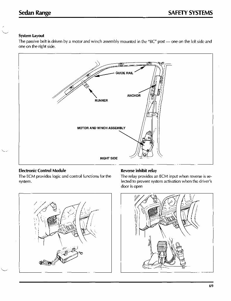
Sedan Range SAFETY SYSTEMS
System layout The passive belt is driven by a motor and winch assembly mounted in the "BC" post- one on the left side and one on the right side.
RIGHT SIDE
Electronic Control Module The ECM provides logic and control functions for the system.
Reverse inhibit relay The relay provides an ECM input when reverse is selected to prevent system activation when the driver's door is open
69

SAFETY SYSTEMS Sedan Range
• WO I I IGNITION SWITCHED BATTERY
WY GROUNDS POWER SUPPLY
) NS 0><0 RIGHT FUSE PANEL
#A420A
) NS 0><0 LEFT FUSE PANEL
#A420A YO YO
G
I -87A G G ~( ,- 'f -, CENTER FUSE PANEL
~ WB WB #93A REVERSE
~ IGNITION SWITCHED
INHIBIT POWER SUPPLY RELAY
SLG SLG SLG SLG -- --
~~ YG
REAR ,] LEFT
FRONT MOTOR SLG REVERSE
YN LIGHTS
-----· .--=!---- YW
FRONT 8 3 RIGHT
REAR MOTOR
-· YU
GW GW
SLG SLG
I I FRONTDOCK YB - "1 ,- • • •
r- YLG I - I REAR DOCK
I I
YR I - I PROXIMITY
1 L J r- BK LEFT SWITCHES
I - I PROXIMITY YO
1 I I
~ r- yp I - I REAR DOCK
I I I ;--; I FRONT DOCK YS • "1 ,-
PASSIVE RESTRAINT RIGHT SWITCHES
ECU -=-
PASSIVE RESTRAINT SEDAN RANGE 4.0 1991 -92 MODEL YEARS
70
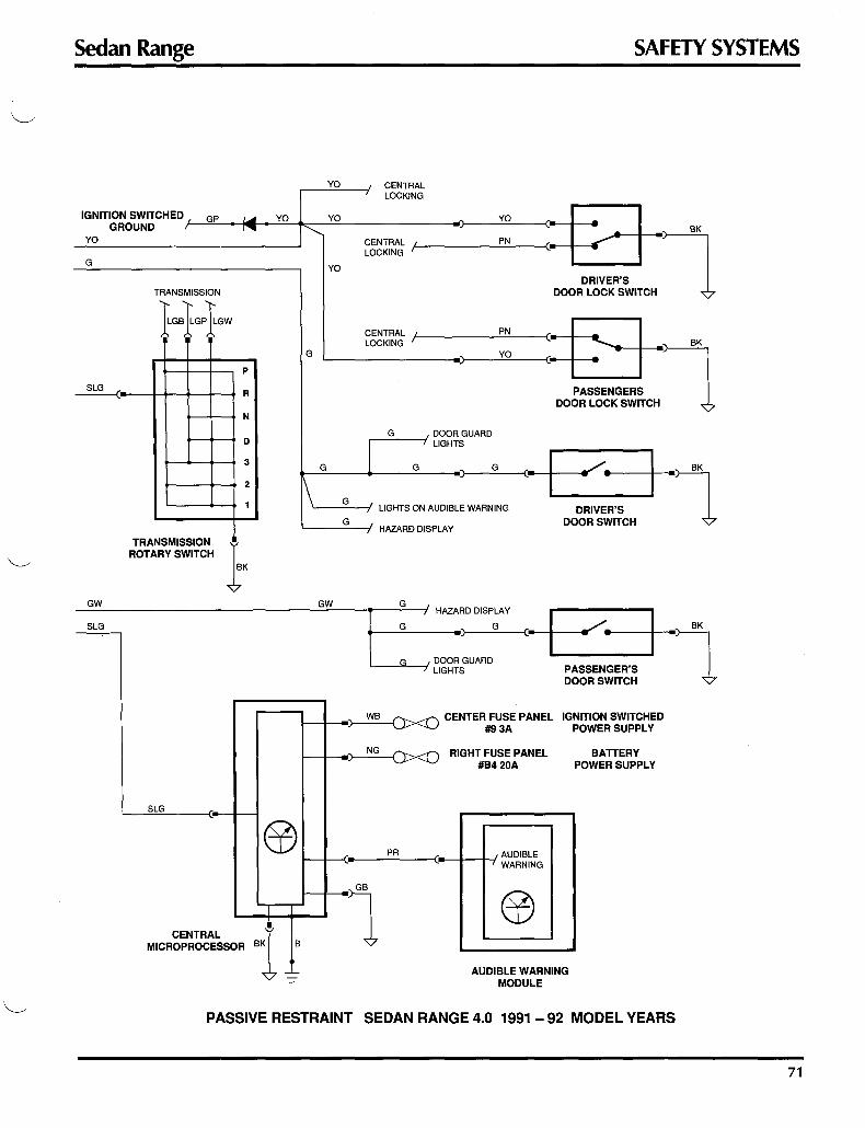
Sedan Range
G
GW
SLG
TRANSMISSION
1GB1GP1GW
p
R
N
D
3
2
1
TRANSMISSION ROTARY SWITCH }
SLG
CENTRAL MICROPROCESSOR
YO
YO
YO
G
G
GW
SAFETY SYSTEMS
CENTRAL LOCKING
) YO '2 " CENTRAL PN LOCKING
DRIVER'S l DOOR LOCK SWITCH
CENTRAL PN fl" LOCKING YO
PASSENGERS l DOOR LOCK SWITCH
G DOOR GUARD LIGHTS
G )
G C• .-/. I "1 LIGHTS ON AUDIBLE WARNING DRIVER'S
DOOR SWITCH HAZARD DISPLAY
l : ,: HAZARD DISP:Y
•) C•--t- ......-; ..... --11------•lBK .______,G..._-1 DOOR GUARD
LIGHTS PASSENGER'S DOOR SWITCH
r--+-"- ~~ CENTER FUSE PANEL IGNITION SWITCHED ·~ #9 3A POWER SUPPLY
t--+-~ RIGHT FUSE PANEL #B4 20A
BATTERY POWER SUPPLY
Ee l---+-{r. ___ PR ___ 0_-+---+-f AUDIBLE
,- WARNING
i,l,
BK ---
B 1 AUDIBLE WARNING
MODULE
PASSIVE RESTRAINT SEDAN RANGE 4.0 1991 - 92 MODEL YEARS
71

SAFETY SYSTEMS XJS Range
PASSIVE RESTRAINT SEAT BELT SYSTEM: 1988-89 MY COUPE
The passive belt is a single diagonal seat belt fed from an inertia reel assembly mounted on the inside seat slide and connecting to a motorized runner mounted on the upper door opening.
A quick-release emergency buckle attaches at the runner. A second independent lap belt is fed from an inertia reel assembly mounted on the outside seat slide. It connects manually to the anchor on the inside seat slide.
Two warnings are provided: a 6-second audible warning and a warning light. The warning light on the instrument panel will come on if the passive restraint belt does not locate in the driver's side anchor or if it is not connected to the runner.
ANCHOR EMERGENCY BUCKLE
72

XJS Range SAFETY SYSTEMS
The system is driven by a motor and winch assembly located under the lower rear quarter trim panel -one on the left side and one on the right side.
To release a diagonal belt in an emergency, press the red button marked PRESS at the shoulder end.
RUNNER
RIGHT SIDE
The system is actuated when the following occur:
"-----" • The driver's seat cushion sensor pad weight switch is actuated.
• Both doors are closed.
• The key is inserted in the ignition switch.
The operation is as follows:
MOTOR AND WINCH ASSEMBLY
• When the driver's seat is occupied with both doors closed and the key is in the ignition, both the left and right diagonal belts will deploy to the restrained position.
• The right belt deploys even if the seat is unoccupied. This action prevents the right belt from obstructing the driver's view.
• The diagonal belt travels to the unrestrained position when either the ignition key is removed or the adjacent door is opened.
• If reverse gear is selected, the reverse inhibit relay is energized to prevent the driver's diagonal belt from traveling to the unrestrained position if the driver's door is opened. This will prevent the driver's being caught by the moving belt if he or she wishes to lean out the door while backing up.
Two warnings are provided:
• The instrument panel seat belt warning light will come on when the driver's seat is occupied (with the doors closed and the ignition key turned to position 2). It will stay on until the diagonal belt has traveled to the restrained position. The diagonal belt must be connected to the runner to activate the belt proximity switch, which will turn off the warning.
• If the diagonal belt has not traveled to the restrained position, an audible warning will sound for approximately 6 seconds after the ignition key has been turned to position 2.
NOTE: An audible warning will also sound continuously if the driver's door is open with the key in the ignition.
73

SAFETY SYSTEMS XJS Range
DRIVERS AIRBAG SYSTEM: 1990 MY ON The driver's airbag system is a fully mechanical system that is one component of an integrated supplementary safety system. The airbag deploys if the vehicle experiences a crash pulse equal to a frontal impact into a solid barrier at or above 6 mph. The complete safety system consists of the following components:
• steering wheel • knee bolster
• upper steering column
• vehicle structure and components
• active seat belts
Steering wheel
• airbag assembly
• arming I disarming mechanism
ARMING I DISARMING MECHANISM
The steering wheel houses the airbag assembly and the arming I disarming mechanism. The steering wheel also transmits the crash pulse to the airbag sensors (via the inflator I sensor housing).
Upper steering column The upper steering column assembly transmits the crash pulse to the steering wheel. In the event of a frontal impact, the steering column collapses to absorb impact energy.
Vehicle structure and components In the event of a frontal impact, the body structure will deform and absorb impact energy. The crash pulse is transmitted through the body to the steering column.
Active seat belts The airbag system is designed as a supplement to the active seat belt system and the other safety system components. The seat belts should be used at all times when the vehicle is in operation.
Knee bolster The driver's side under-dash panel is padded and incorporates a knee bolster. Necessary changes have been ''---../ made to the climate control ducting and the location of electrical components.
74

XJS Range SAFETY SYSTEMS
Airbag assembly The airbag assembly contains the airbag, the inflator I sensor assembly and the inflator I sensor housing. The assembly is enclosed by a trimmed cover that splits horizontally as the airbag inflates.
Note: The airbag assembly is non-serviceable and must not be transferred for use in other vehicles.
Inflator I sensor assembly The inflator I sensor assembly triggers the airbag deployment if it senses a crash pulse equal to a frontal impact into a solid barrier at or above 6 mph. Through the operating mechanism, two firing pins ignite a primer, which in turn reacts with a propellant to produce nitrogen gas and inflate the airbag.
"D" SHAFT
BIAS SPRING PRIMER INITIATOR
If the specified impact occurs, two spherical"sensing masses" move forward against levers which rotate the "D" shafts. Two bias springs return the "D" shafts to their seated positions if an impact is insufficient to fully trigger the sensing masses. The "D" shafts can be prevented from rotating by carrying out a disarming procedure so that service and maintenance work to be safely conducted.
A WARNING: DO NOT ATTEMPT SERVICE OR MAINTENANCE WORK ON THE AIRBAG SYSTEM WITHOUT THE JAGUAR SPECIFIED TOOLS, EQUIPMENT AND SERVICE PROCEDURES. DO NOT REMOVE THE STEERING COLUMN OR STEERING WHEEL FROM THE VEHICLE WITHOUT FIRST DISARMING AND REMOVING THE AIRBAG ASSEMBLY.
75

SAFETY SYSTEMS XJS Range
DRIVER'S AIRBAG (continued) Arming I disarming mechanism The mechanism allows safe service and maintenance of the steering-related components. The arming/ disarming mechanism is built into the inflator I sensing assembly. Arming and disarming are determined by the position of the arming screw in the steering wheel hub.
Armed Condition When screwed fully clockwise against the stop, the arming screw forces the chamfered safety shaft between the two safety levers. The levers are held away from the "D" shafts, allowing the "D" shafts to be triggered by the sensing masses.
SAFETY LEVER SAFETY LEVER
"D" SHAFT
SAFETY LEVER SAFETY SHAFT SAFETY LEVER
76
/----....

XJS Range SAFETY SYSTEMS
Disarmed Condition When screwed fully counter-clockwise against the stop, spring pressure moves the safety shaft away from the safety levers. The safety levers return to their rest position in the safety shaft recess and prevent any movement of the sensing masses.
SAFETY LEVER
SAFETY LEVER
"D" SHAFT
SAFETY SHAFT
SAFETY LEVER
77

SAFETY SYSTEMS XJS Range
AIRBAG SYSTEM OPERATION
AIRBAG CROSS-SECTION
FILTER SENSING MASS AIRBAG
Crash sensing In the event of a frontal impact, the vehicle body structure will deform, absorbing the energy of the impact. The crash pulse is transmitted to the steering column, then to the steering wheel, then to the inflator I sensor.
Airbag deployment If the dash pulse is of sufficient strength and duration, the sensing masses move forward and rotate the "D" shafts. The "D" shafts release the firing pins to ignite the primer. The primer reacts with the propellant to produce nitrogen gas and inflate the airbag.
Driver protection The airbag fills with nitrogen gas and expands, splitting open the airbag cover. The airbag continues to expand until it is fully inflated. The driver travels forward until contact is made with the fully inflated airbag, at which time the driver's forward motion is decelerated. As the driver travels into the airbag, the nitrogen is expelled via the vent hole in the rear of the airbag, thus absorbing impact energy. Simultaneously, the steering column collapses, absorbing additional impact energy until the driver comes to rest. Impact energy is also absorbed by the deformation of the steering wheel and the steering column brackets.
Airbag replacement The airbag assembly is designed for one deployment only. If deployed, the complete assembly and the cover must be replaced and armed.
78
A WARNING: REFER TO TECHNICAL BULLETINS AND THE XJS REPAIR MANUAL FOR SAFETY PRECAUTIONS BEFORE HANDLING AN AIRBAG.
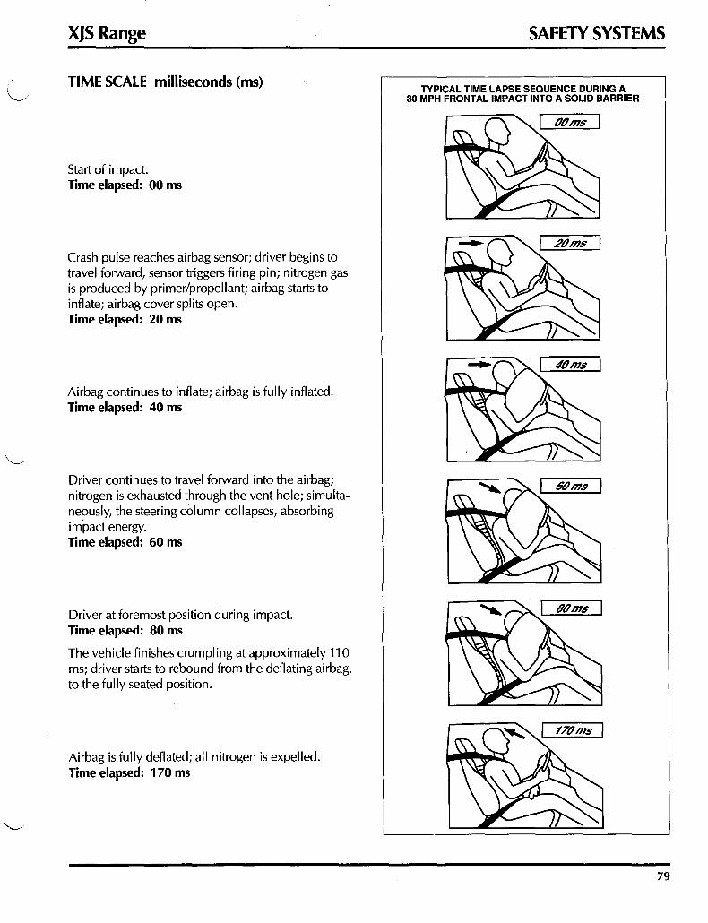
XJS Range
TIME SCALE milliseconds (ms)
Start of impact. Time elapsed: 00 ms
Crash pulse reaches airbag sensor; driver begins to travel forward, sensor triggers firing pin; nitrogen gas is produced by primer/propellant; airbag starts to inflate; airbag cover splits open. Time elapsed: 20 ms
Airbag continues to inflate; airbag is fully inflated. Time elapsed: 40 ms
Driver continues to travel forward into the airbag; nitrogen is exhausted through the vent hole; simultane?usly, the steering column collapses, absorbing impact energy. Time elapsed: 60 ms
Driver at foremost position during impact. Time elapsed: 80 ms
The vehicle finishes crumpling at approximately 110 ms; driver starts to rebound from the deflating airbag, to the fully seated position.
Airbag is fully deflated; all nitrogen is expelled. Time elapsed: 170 ms
SAFETY SYSTEMS
TYPICAL TIME LAPSE SEQUENCE DURING A 30 MPH FRONTAL IMPACT INTO A SOLID BARRIER
79
