servo control facts - infoplc
TRANSCRIPT
SERVO CONTROL FACTSA HANDBOOK EXPLAINING
THE BASICS OF MOTION
BALDOR ELECTRIC COMPANY
MN1205
www.infoPLC.net
TABLE OF CONTENTS
TYPES OF MOTORS . . . . . . . . . . . . . . 3
OPEN LOOP/CLOSED LOOP . . . . . 9
WHAT IS A SERVO . . . . . . . . . . . . . . 11
COMPENSATION . . . . . . . . . . . . . . . 13
TYPES OF CONTROLS . . . . . . . . . . . 15
TYPES OF FEEDBACK DEVICES . 17
TYPES OF ACTUATORS . . . . . . . . . . 22
Page 2
www.infoPLC.net
Page 3
Servo Control Facts
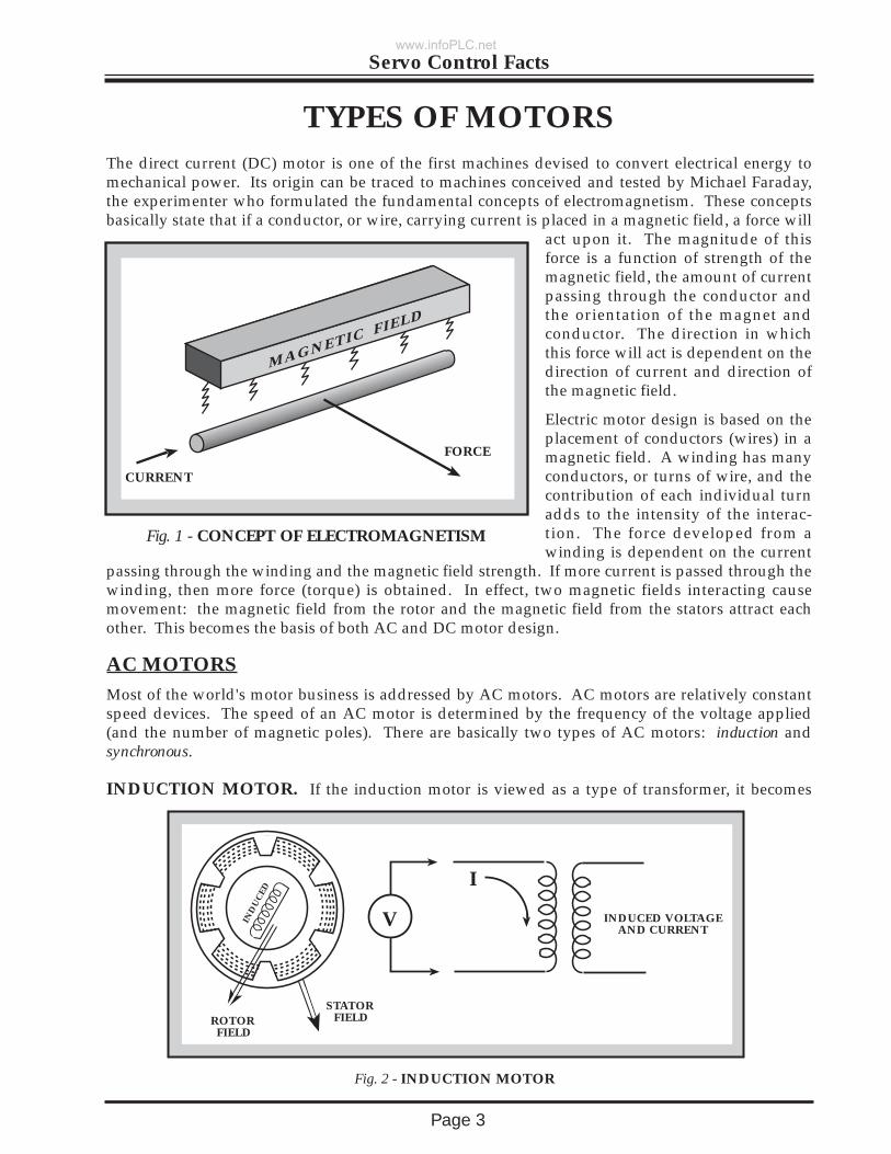
TYPES OF MOTORSThe direct current (DC) motor is one of the first machines devised to convert electrical energy tomechanical power. Its origin can be traced to machines conceived and tested by Michael Faraday,the experimenter who formulated the fundamental concepts of electromagnetism. These conceptsbasically state that if a conductor, or wire, carrying current is placed in a magnetic field, a force will
act upon it. The magnitude of thisforce is a function of strength of themagnetic field, the amount of currentpassing through the conductor andthe orientation of the magnet andconductor. The direction in whichthis force will act is dependent on thedirection of current and direction ofthe magnetic field.
Electric motor design is based on theplacement of conductors (wires) in amagnetic field. A winding has manyconductors, or turns of wire, and thecontribution of each individual turnadds to the intensity of the interac-tion. The force developed from awinding is dependent on the current
passing through the winding and the magnetic field strength. If more current is passed through thewinding, then more force (torque) is obtained. In effect, two magnetic fields interacting causemovement: the magnetic field from the rotor and the magnetic field from the stators attract eachother. This becomes the basis of both AC and DC motor design.
AC MOTORSMost of the world's motor business is addressed by AC motors. AC motors are relatively constantspeed devices. The speed of an AC motor is determined by the frequency of the voltage applied(and the number of magnetic poles). There are basically two types of AC motors: induction andsynchronous.
INDUCTION MOTOR. If the induction motor is viewed as a type of transformer, it becomes
MAGNETIC FIELD
CURRENT
FORCE
Fig. 1 - CONCEPT OF ELECTROMAGNETISM
ROTOR FIELD
STATOR FIELD
INDUCED VOLTAGEAND CURRENT
Fig. 2 - INDUCTION MOTOR
IND
UC
ED
V
I
www.infoPLC.net
Page 4
Servo Control Facts
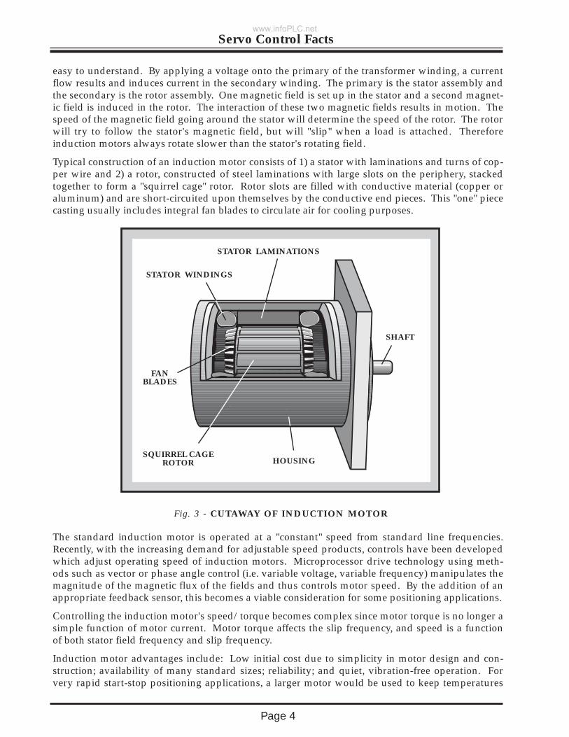
easy to understand. By applying a voltage onto the primary of the transformer winding, a currentflow results and induces current in the secondary winding. The primary is the stator assembly andthe secondary is the rotor assembly. One magnetic field is set up in the stator and a second magnet-ic field is induced in the rotor. The interaction of these two magnetic fields results in motion. Thespeed of the magnetic field going around the stator will determine the speed of the rotor. The rotorwill try to follow the stator's magnetic field, but will "slip" when a load is attached. Thereforeinduction motors always rotate slower than the stator's rotating field.
Typical construction of an induction motor consists of 1) a stator with laminations and turns of cop-per wire and 2) a rotor, constructed of steel laminations with large slots on the periphery, stackedtogether to form a "squirrel cage" rotor. Rotor slots are filled with conductive material (copper oraluminum) and are short-circuited upon themselves by the conductive end pieces. This "one" piececasting usually includes integral fan blades to circulate air for cooling purposes.
The standard induction motor is operated at a "constant" speed from standard line frequencies.Recently, with the increasing demand for adjustable speed products, controls have been developedwhich adjust operating speed of induction motors. Microprocessor drive technology using meth-ods such as vector or phase angle control (i.e. variable voltage, variable frequency) manipulates themagnitude of the magnetic flux of the fields and thus controls motor speed. By the addition of anappropriate feedback sensor, this becomes a viable consideration for some positioning applications.
Controlling the induction motor's speed/torque becomes complex since motor torque is no longer asimple function of motor current. Motor torque affects the slip frequency, and speed is a functionof both stator field frequency and slip frequency.
Induction motor advantages include: Low initial cost due to simplicity in motor design and con-struction; availability of many standard sizes; reliability; and quiet, vibration-free operation. Forvery rapid start-stop positioning applications, a larger motor would be used to keep temperatures
Fig. 3 - CUTAWAY OF INDUCTION MOTOR
STATOR LAMINATIONS
STATOR WINDINGS
SQUIRREL CAGEROTOR
FANBLADES
SHAFT
HOUSING
www.infoPLC.net

Page 5
Servo Control Facts
within design limits. A low torque to inertia ratio limits this motor type to less demanding incre-menting (start-stop) applications.
SYNCHRONOUS MOTOR. The synchronous motor is basically the same as the inductionmotor but with slightly different rotor construction. The rotor construction enables this type ofmotor to rotate at the same speed (in synchronization) as the stator field. There are basically twotypes of synchronous motors: self excited ( as the induction motor) and directly excited (as with per-manent magnets).
The self excited motor (may be called reluctance synchronous) includes a rotor with notches, orteeth, on the periphery. The number of notches corresponds to the number of poles in the stator.Oftentimes the notches or teeth are termed salient poles. These salient poles create an easy path forthe magnetic flux field, thus allowing the rotor to "lock in" and run at the same speed as therotating field.
A directly excited motor (may be called hysteresis synchronous, or AC permanent magnet synchro-nous) includes a rotor with a cylinder of a permanent magnet alloy. The permanent magnet northand south poles, in effect, are the salient teeth of this design, and therefore prevent slip.
In both the self excited and directly excited types there is a "coupling" angle, i.e. the rotor lags a
small distance behind the stator field. This angle will increase with load, and if the load isincreased beyond the motor's capability, the rotor will pull out of synchronism.
The synchronous motor is generally operated in an "open loop" configuration and within the limi-
Fig. 4 - CUTAWAY OF AC SYNCHRONOUS MOTOR
STATOR
SHAFT
ROTOR
STATOR LAMINATIONS
STATOR WINDINGS
ROTORWITH TEETHOR NOTCHES
HOUSING
SHAFT
www.infoPLC.net
Page 6
Servo Control Facts
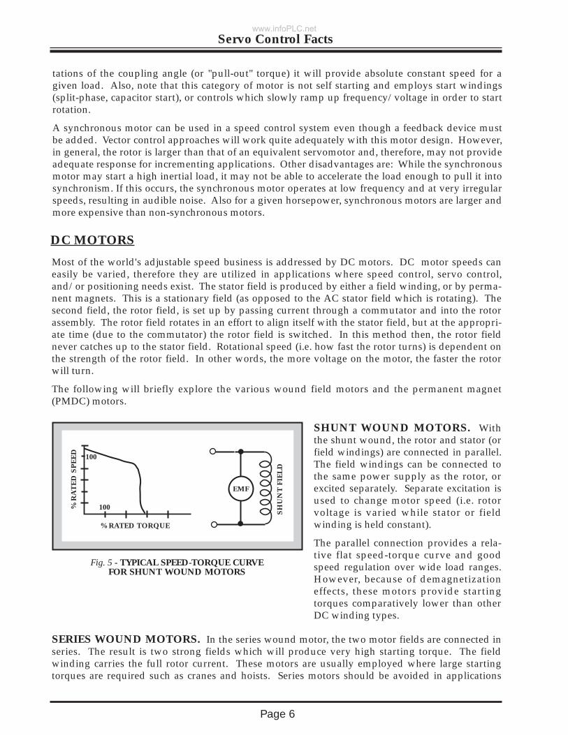
SHUNT WOUND MOTORS. Withthe shunt wound, the rotor and stator (orfield windings) are connected in parallel.The field windings can be connected tothe same power supply as the rotor, orexcited separately. Separate excitation isused to change motor speed (i.e. rotorvoltage is varied while stator or fieldwinding is held constant).
The parallel connection provides a rela-tive flat speed-torque curve and goodspeed regulation over wide load ranges.However, because of demagnetizationeffects, these motors provide startingtorques comparatively lower than otherDC winding types.
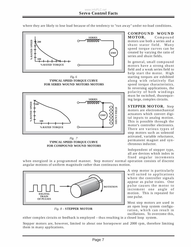
SERIES WOUND MOTORS. In the series wound motor, the two motor fields are connected inseries. The result is two strong fields which will produce very high starting torque. The fieldwinding carries the full rotor current. These motors are usually employed where large startingtorques are required such as cranes and hoists. Series motors should be avoided in applications
tations of the coupling angle (or "pull-out" torque) it will provide absolute constant speed for agiven load. Also, note that this category of motor is not self starting and employs start windings(split-phase, capacitor start), or controls which slowly ramp up frequency/voltage in order to startrotation.
A synchronous motor can be used in a speed control system even though a feedback device mustbe added. Vector control approaches will work quite adequately with this motor design. However,in general, the rotor is larger than that of an equivalent servomotor and, therefore, may not provideadequate response for incrementing applications. Other disadvantages are: While the synchronousmotor may start a high inertial load, it may not be able to accelerate the load enough to pull it intosynchronism. If this occurs, the synchronous motor operates at low frequency and at very irregularspeeds, resulting in audible noise. Also for a given horsepower, synchronous motors are larger andmore expensive than non-synchronous motors.
DC MOTORS
Most of the world's adjustable speed business is addressed by DC motors. DC motor speeds caneasily be varied, therefore they are utilized in applications where speed control, servo control,and/or positioning needs exist. The stator field is produced by either a field winding, or by perma-nent magnets. This is a stationary field (as opposed to the AC stator field which is rotating). Thesecond field, the rotor field, is set up by passing current through a commutator and into the rotorassembly. The rotor field rotates in an effort to align itself with the stator field, but at the appropri-ate time (due to the commutator) the rotor field is switched. In this method then, the rotor fieldnever catches up to the stator field. Rotational speed (i.e. how fast the rotor turns) is dependent onthe strength of the rotor field. In other words, the more voltage on the motor, the faster the rotorwill turn.
The following will briefly explore the various wound field motors and the permanent magnet(PMDC) motors.
% R
AT
ED
SP
EE
D
% RATED TORQUE
100
100
EMF
SH
UN
T F
IEL
D
Fig. 5 - TYPICAL SPEED-TORQUE CURVEFOR SHUNT WOUND MOTORS
www.infoPLC.net
Page 7
Servo Control Facts
COMPOUND WOUNDMOTOR. Compoundmotors use both a series and ashunt stator field. Manyspeed torque curves can becreated by varying the ratio ofseries and shunt fields.
In general, small compoundmotors have a strong shuntfield and a weak series field tohelp start the motor. Highstarting torques are exhibitedalong with relatively flatspeed torque characteristics.In reversing applications, thepolarity of both windingsmust be switched, thusrequir-ing large, complex circuits.
where they are likely to lose load because of the tendency to "run away" under no-load conditions.
SERIES
EMF
Fig. 6 TYPICAL SPEED-TORQUE CURVE
FOR SERIES WOUND MOTORS MOTORS
% R
AT
ED
SP
EE
D
% RATED TORQUE
100
200
STEPPER MOTOR. Stepmotors are electromechanicalactuators which convert digi-tal inputs to analog motion.This is possible through themotor's controller electronics.There are various types ofstep motors such as solenoidactivated, variable reluctance,permanent magnet and syn-chronous inductor.
Independent of stepper type,all are devices which index infixed angular increments
when energized in a programmed manner. Step motors' normal operation consists of discreteangular motions of uniform magnitude rather than continuous motion.
A step motor is particularlywell suited to applicationswhere the controller signalsappear as pulse trains. Onepulse causes the motor toincrement one angle ofmotion. This is repeated forone pulse.
Most step motors are used inan open loop system configu-ration, which can result inoscillations. To overcome this,
either complex circuits or feedback is employed – thus resulting in a closed loop system.
Stepper motors are, however, limited to about one horsepower and 2000 rpm, therefore limitingthem in many applications.
DIGITALTRAIN
OF PULSES
ROTATION
Fig. 8 - STEPPER MOTOR
% R
AT
ED
SP
EE
D
% RATED TORQUE
100
100
SERIES
EMFS
HU
NT
FIE
LD
Fig. 7TYPICAL SPEED-TORQUE CURVE
FOR COMPOUND WOUND MOTORS
www.infoPLC.net
Page 8
Servo Control Facts
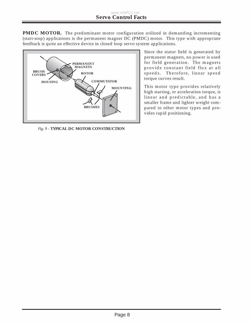
PMDC MOTOR. The predominant motor configuration utilized in demanding incrementing(start-stop) applications is the permanent magnet DC (PMDC) motor. This type with appropriatefeedback is quite an effective device in closed loop servo system applications.
Since the stator field is generated bypermanent magnets, no power is usedfor field generation. The magnetsprovide constant field flux at allspeeds. Therefore, linear speedtorque curves result.
This motor type provides relativelyhigh starting, or acceleration torque, islinear and predictable, and has asmaller frame and lighter weight com-pared to other motor types and pro-vides rapid positioning.
HOUSING
BRUSHCOVERS
PERMANENTMAGNETS
ROTOR
COMMUTATOR
MOUNTING
BRUSHES
Fig. 9 - TYPICAL DC MOTOR CONSTRUCTION
www.infoPLC.net
Page 9
Servo Control Facts
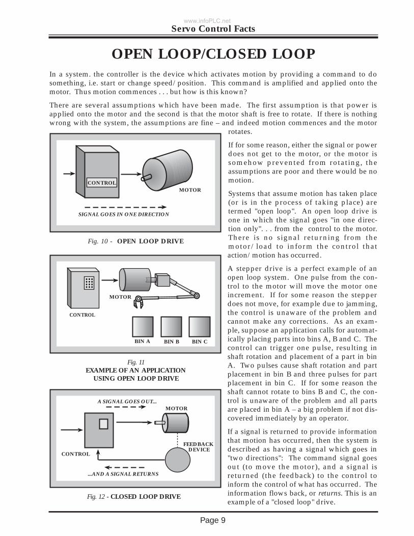
OPEN LOOP/CLOSED LOOPIn a system. the controller is the device which activates motion by providing a command to dosomething, i.e. start or change speed/position. This command is amplified and applied onto themotor. Thus motion commences . . . but how is this known?
There are several assumptions which have been made. The first assumption is that power isapplied onto the motor and the second is that the motor shaft is free to rotate. If there is nothingwrong with the system, the assumptions are fine – and indeed motion commences and the motor
rotates.
If for some reason, either the signal or powerdoes not get to the motor, or the motor issomehow prevented from rotating, theassumptions are poor and there would be nomotion.
Systems that assume motion has taken place(or is in the process of taking place) aretermed "open loop". An open loop drive isone in which the signal goes "in one direc-tion only". . . from the control to the motor.There is no signal returning from themotor/load to inform the control thataction/motion has occurred.
A stepper drive is a perfect example of anopen loop system. One pulse from the con-trol to the motor will move the motor oneincrement. If for some reason the stepperdoes not move, for example due to jamming,the control is unaware of the problem andcannot make any corrections. As an exam-ple, suppose an application calls for automat-ically placing parts into bins A, B and C. Thecontrol can trigger one pulse, resulting inshaft rotation and placement of a part in binA. Two pulses cause shaft rotation and partplacement in bin B and three pulses for partplacement in bin C. If for some reason theshaft cannot rotate to bins B and C, the con-trol is unaware of the problem and all partsare placed in bin A – a big problem if not dis-covered immediately by an operator.
If a signal is returned to provide informationthat motion has occurred, then the system isdescribed as having a signal which goes in"two directions": The command signal goesout (to move the motor), and a signal isreturned (the feedback) to the control toinform the control of what has occurred. Theinformation flows back, or returns. This is anexample of a "closed loop" drive.
SIGNAL GOES IN ONE DIRECTION
MOTORCONTROL
Fig. 10 - OPEN LOOP DRIVE
CONTROL
BIN A BIN B BIN C
Fig. 11EXAMPLE OF AN APPLICATION
USING OPEN LOOP DRIVE
MOTOR
A SIGNAL GOES OUT...
CONTROL
MOTOR
FEEDBACK DEVICE
...AND A SIGNAL RETURNS
Fig. 12 - CLOSED LOOP DRIVE
www.infoPLC.net
Page 10
Servo Control Facts
The return signal (feedback signal) provides the means to monitor the process for correctness.From the automatic pick and place application example previously cited, if the shaft cannot rotateto bins B and C, the feedback will inform the control of an error and the control can activate a lightor a horn to alert the operator of the problem.
When would an application use an open loop approach? First of all, just think of how simple itwould be to hook up – a few wires and no adjustments. Stepper motors are traditionally employedin open loop systems . . . they are easy to wire, they interface easily with the user's digital computerand they provide good position repeatability. Stepper motors, however, are limited to approxi-mately one horsepower. Their upper speed limit is about 2000 rpm.
The weaknesses of the open loop approach include: It is not good for applications with varyingloads, it is possible for a stepper motor to lose steps, its energy efficiency level is low and it has res-onance areas which must be avoided.
What applications use the closed loop technique? Those that require control over a variety of com-plex motion profiles. These may involve the following: control of either velocity and/or position;high resolution and accuracy; velocity may be either very slow, or very high; and the applicationmay demand high torques in a small package size.
Because of additional components such as the feedback device, complexity is considered by someto be a weakness of the closed loop approach. These additional components do add to initial cost(an increase in productivity is typically not considered when investigating cost). Lack of under-standing does give the impression to the user of difficulty.
In many applications, whether the open loop or closed loop techniques employed often comesdown to the basic decision of the user . . . and the approach with which he/she is most knowledge-able/comfortable with.
www.infoPLC.net
Page 11
Servo Control Facts
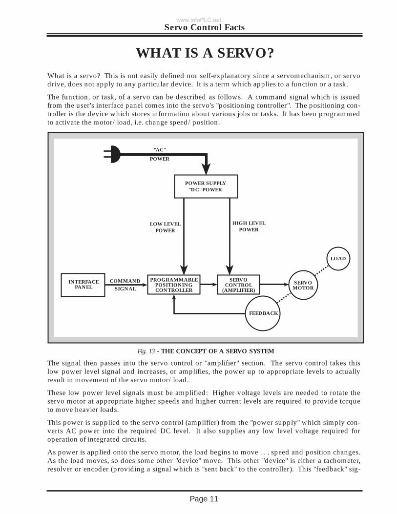
WHAT IS A SERVO?What is a servo? This is not easily defined nor self-explanatory since a servomechanism, or servodrive, does not apply to any particular device. It is a term which applies to a function or a task.
The function, or task, of a servo can be described as follows. A command signal which is issuedfrom the user's interface panel comes into the servo's "positioning controller". The positioning con-troller is the device which stores information about various jobs or tasks. It has been programmedto activate the motor/load, i.e. change speed/position.
The signal then passes into the servo control or "amplifier" section. The servo control takes thislow power level signal and increases, or amplifies, the power up to appropriate levels to actuallyresult in movement of the servo motor/load.
These low power level signals must be amplified: Higher voltage levels are needed to rotate theservo motor at appropriate higher speeds and higher current levels are required to provide torqueto move heavier loads.
This power is supplied to the servo control (amplifier) from the "power supply" which simply con-verts AC power into the required DC level. It also supplies any low level voltage required foroperation of integrated circuits.
As power is applied onto the servo motor, the load begins to move . . . speed and position changes.As the load moves, so does some other "device" move. This other "device" is either a tachometer,resolver or encoder (providing a signal which is "sent back" to the controller). This "feedback" sig-
COMMAND
SIGNAL
"AC"
POWER
LOW LEVELPOWER
HIGH LEVELPOWER
SERVO MOTOR
FEEDBACK
LOAD
SERVO CONTROL
(AMPLIFIER)
PROGRAMMABLE POSITIONINGCONTROLLER
INTERFACEPANEL
POWER SUPPLY"DC" POWER
Fig. 13 - THE CONCEPT OF A SERVO SYSTEM
www.infoPLC.net
Page 12
Servo Control Facts
nal is informing the positioning controller whether the motor is doing the proper job.
The positioning controller looks at this feedback signal and determines if the load is being movedproperly by the servo motor; and, if not, then the controller makes appropriate corrections. Forexample, assume the command signal was to drive the load at 1000 rpm. For some reason it isactually rotating at 900 rpm. The feedback signal will inform the controller that the speed is 900rpm. The controller then compares the command signal (desired speed) of 1000 rpm and the feed-back signal (actual speed) of 900 rpm and notes an error. The controller then outputs a signal toapply more voltage onto the servo motor to increase speed until the feedback signal equals thecommand signal, i.e. there is no error.
Therefore, a servo involves several devices. It is a system of devices for controlling some item(load). The item (load) which is controlled (regulated) can be controlled in any manner, i.e. posi-tion, direction, speed. The speed or position is controlled in relation to a reference (command sig-nal), as long as the proper feedback device (error detection device) is used. The feedback and com-mand signals are compared, and the corrections made. Thus, the definition of a servo system is,that it consists of several devices which control or regulate speed/position of a load.
www.infoPLC.net
Page 13
Servo Control Facts
COMPENSATIONWhy must servos be compensated? Simply stated, it is required so that the controller andmotor/load i.e. machine will operate properly. The machine must produce accurate parts and havehigh productivity.
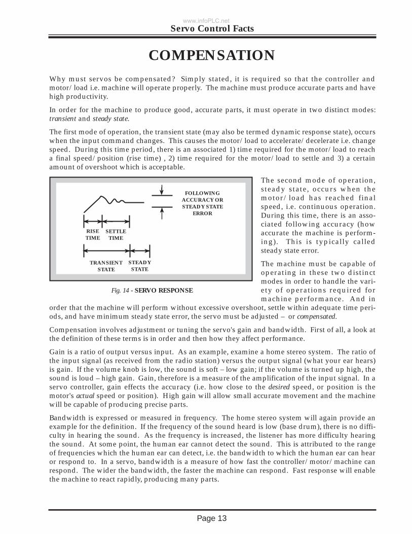
In order for the machine to produce good, accurate parts, it must operate in two distinct modes:transient and steady state.
The first mode of operation, the transient state (may also be termed dynamic response state), occurswhen the input command changes. This causes the motor/load to accelerate/decelerate i.e. changespeed. During this time period, there is an associated 1) time required for the motor/load to reacha final speed/position (rise time) , 2) time required for the motor/load to settle and 3) a certainamount of overshoot which is acceptable.
The second mode of operation,steady state, occurs when themotor/load has reached finalspeed, i.e. continuous operation.During this time, there is an asso-ciated following accuracy (howaccurate the machine is perform-ing). This is typically calledsteady state error.
The machine must be capable ofoperating in these two distinctmodes in order to handle the vari-ety of operations required formachine performance. And in
order that the machine will perform without excessive overshoot, settle within adequate time peri-ods, and have minimum steady state error, the servo must be adjusted – or compensated.
Compensation involves adjustment or tuning the servo's gain and bandwidth. First of all, a look atthe definition of these terms is in order and then how they affect performance.
Gain is a ratio of output versus input. As an example, examine a home stereo system. The ratio ofthe input signal (as received from the radio station) versus the output signal (what your ear hears)is gain. If the volume knob is low, the sound is soft – low gain; if the volume is turned up high, thesound is loud – high gain. Gain, therefore is a measure of the amplification of the input signal. In aservo controller, gain effects the accuracy (i.e. how close to the desired speed, or position is themotor's actual speed or position). High gain will allow small accurate movement and the machinewill be capable of producing precise parts.
Bandwidth is expressed or measured in frequency. The home stereo system will again provide anexample for the definition. If the frequency of the sound heard is low (base drum), there is no diffi-culty in hearing the sound. As the frequency is increased, the listener has more difficulty hearingthe sound. At some point, the human ear cannot detect the sound. This is attributed to the rangeof frequencies which the human ear can detect, i.e. the bandwidth to which the human ear can hearor respond to. In a servo, bandwidth is a measure of how fast the controller/motor/machine canrespond. The wider the bandwidth, the faster the machine can respond. Fast response will enablethe machine to react rapidly, producing many parts.
FOLLOWINGACCURACY ORSTEADY STATE
ERROR
RISETIME
SETTLETIME
TRANSIENTSTATE
STEADYSTATE
Fig. 14 - SERVO RESPONSE
www.infoPLC.net
Page 14
Servo Control Facts
Why then, are not all servos designed with high gain (high accuracy) and wide bandwidth (fastresponse)? This is attributed to 1) limitations of the components and 2) resonant conditions.
Limits of the components – they can handle only so much power. In addition, increasing gain addscomponents, cost, complexity.
Resonant conditions – To explain this, imagine a yard stick held in your hand. Slowly move it upand down. . . note that the far end of the rod will follow your hand movement. As movement isincreased (increasing frequency of motion) the far end of the yard stick will bend in its attempt tokeep up with your hand movements. At some frequency it is possible to break the stick . . . this isthe resonant point.
Just as with this example, all systems have a resonant point, whether that system is a bridge, a tankor a servo. Machines must not be operated at the resonant point otherwise instability and severedamage will occur.
In conclusion, servos are compensated or "tuned" via adjustments of gain and response so that themachine will produce accurate parts at a high productivity rate.
www.infoPLC.net
Page 15
Servo Control Facts
TYPES OF CONTROLSThe control of a motor will employ some type of power semiconductor. These devices regulate theamount of power being applied onto the motor, and moving the load.
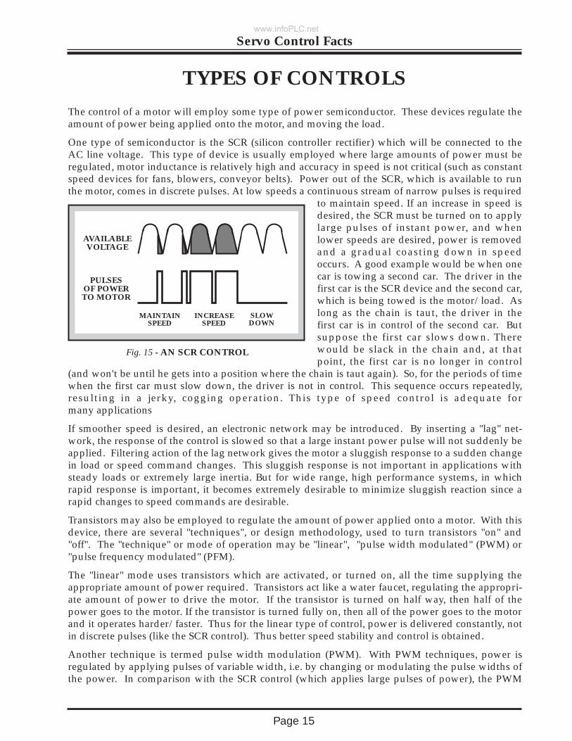
One type of semiconductor is the SCR (silicon controller rectifier) which will be connected to theAC line voltage. This type of device is usually employed where large amounts of power must beregulated, motor inductance is relatively high and accuracy in speed is not critical (such as constantspeed devices for fans, blowers, conveyor belts). Power out of the SCR, which is available to runthe motor, comes in discrete pulses. At low speeds a continuous stream of narrow pulses is required
to maintain speed. If an increase in speed isdesired, the SCR must be turned on to applylarge pulses of instant power, and whenlower speeds are desired, power is removedand a gradual coasting down in speedoccurs. A good example would be when onecar is towing a second car. The driver in thefirst car is the SCR device and the second car,which is being towed is the motor/load. Aslong as the chain is taut, the driver in thefirst car is in control of the second car. Butsuppose the first car slows down. Therewould be slack in the chain and, at thatpoint, the first car is no longer in control
(and won't be until he gets into a position where the chain is taut again). So, for the periods of timewhen the first car must slow down, the driver is not in control. This sequence occurs repeatedly,resulting in a jerky, cogging operation. This type of speed control is adequate formany applications
If smoother speed is desired, an electronic network may be introduced. By inserting a "lag" net-work, the response of the control is slowed so that a large instant power pulse will not suddenly beapplied. Filtering action of the lag network gives the motor a sluggish response to a sudden changein load or speed command changes. This sluggish response is not important in applications withsteady loads or extremely large inertia. But for wide range, high performance systems, in whichrapid response is important, it becomes extremely desirable to minimize sluggish reaction since arapid changes to speed commands are desirable.
Transistors may also be employed to regulate the amount of power applied onto a motor. With thisdevice, there are several "techniques", or design methodology, used to turn transistors "on" and"off". The "technique" or mode of operation may be "linear", "pulse width modulated" (PWM) or"pulse frequency modulated" (PFM).
The "linear" mode uses transistors which are activated, or turned on, all the time supplying theappropriate amount of power required. Transistors act like a water faucet, regulating the appropri-ate amount of power to drive the motor. If the transistor is turned on half way, then half of thepower goes to the motor. If the transistor is turned fully on, then all of the power goes to the motorand it operates harder/faster. Thus for the linear type of control, power is delivered constantly, notin discrete pulses (like the SCR control). Thus better speed stability and control is obtained.
Another technique is termed pulse width modulation (PWM). With PWM techniques, power isregulated by applying pulses of variable width, i.e. by changing or modulating the pulse widths ofthe power. In comparison with the SCR control (which applies large pulses of power), the PWM
AVAILABLEVOLTAGE
PULSESOF POWERTO MOTOR
MAINTAINSPEED
INCREASESPEED
SLOW DOWN
Fig. 15 - AN SCR CONTROL
www.infoPLC.net
Page 16
Servo Control Facts
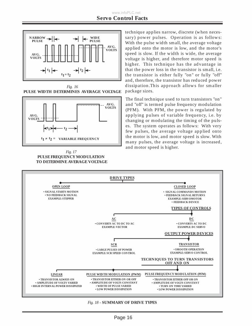
technique applies narrow, discrete (when neces-sary) power pulses. Operation is as follows:With the pulse width small, the average voltageapplied onto the motor is low, and the motor'sspeed is slow. If the width is wide, the averagevoltage is higher, and therefore motor speed ishigher. This technique has the advantage inthat the power loss in the transistor is small, i.e.the transistor is either fully "on" or fully "off"and, therefore, the transistor has reduced powerdissipation.This approach allows for smallerpackage sizes.
The final technique used to turn transistors "on"and "off" is termed pulse frequency modulation(PFM). With PFM, the power is regulated byapplying pulses of variable frequency, i.e. bychanging or modulating the timing of the puls-es. The system operates as follows: With veryfew pulses, the average voltage applied ontothe motor is low, and motor speed is slow. Withmany pulses, the average voltage is increased,and motor speed is higher.
DRIVE TYPES
OPEN LOOP
•SIGNAL STARTS MOTION•NO FEEDBACK SIGNAL
EXAMPLE: STEPPER
CLOSED LOOP
• SIGNAL COMMANDS MOTION•FEEDBACK SIGNAL RETURNS
EXAMPLE: SERVOMOTOR + FEEDBACK DEVICE
TYPES OF CONTROLS
AC DC•CONVERTS AC TO DC TO AC
EXAMPLE: VECTOR•CONVERTS AC TO DCEXAMPLE: DC SERVO
OUTPUT POWER DEVICES
SCR
•LARGE PULSES OF POWEREXAMPLE: SCR SPEED CONTROL
TRANSISTOR
•SMOOTH OPERATIONEXAMPLE: SERVO CONTROL
TECHNIQUES TO TURN TRANSISTORSOFF AND ON
PULSE FREQUENCY MODULATION (PFM)
•TRANSISTOR EITHER OFF OR ON•AMPLITUDE OF VOLTS CONSTANT
•TURN ON TIME VARIED•LOW POWER DISSIPATION
PULSE WIDTH MODULATION (PWM)
•TRANSISTOR EITHER ON OR OFF•AMPLITUDE OF VOLTS CONSTANT
•WIDTH OF PULSE VARIED•LOW POWER DISSIPATION
LINEAR
•TRANSISTOR ALWAYS ON•AMPLITUDE OF VOLTS VARIED
•HIGH INTERNAL POWER DISSIPATED
Fig. 18 - SUMMARY OF DRIVE TYPES
NARROW PULSE
WIDEPULSE
t1 t2t1 t2=
Fig. 16PULSE WIDTH DETERMINES AVERAGE VOLTAGE
AVG.VOLTS
AVG.VOLTS
AVG. VOLTS
AVG. VOLTS
t1 t2 == VARIABLE FREQUENCY
t1 t2
Fig. 17PULSE FREQUENCY MODULATION
TO DETERMINE AVERAGE VOLTAGE
www.infoPLC.net
Page 17
Servo Control Facts
Servos use feedback signals for stabilization, speed and position information. This informationmay come from a variety of devices such as the analog tachometer, the digital tachometer (opticalencoder) or from a resolver. In the following, each of these devices will be defined and the basicsexplored.
TYPES OF FEEDBACK DEVICES
ANALOG TACHOMETERS
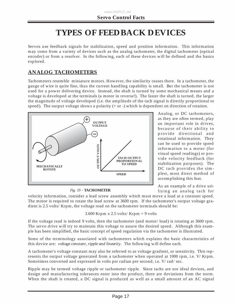
Tachometers resemble miniature motors. However, the similarity ceases there. In a tachometer, thegauge of wire is quite fine, thus the current handling capability is small. But the tachometer is notused for a power delivering device. Instead, the shaft is turned by some mechanical means and avoltage is developed at the terminals (a motor in reverse!). The faster the shaft is turned, the largerthe magnitude of voltage developed (i.e. the amplitude of the tach signal is directly proportional tospeed). The output voltage shows a polarity (+ or -) which is dependent on direction of rotation.
Analog, or DC tachometers,as they are often termed, playan important role in drives,because of their ability toprovide directional androtational information. Theycan be used to provide speedinformation to a meter (forvisual speed readings) or pro-vide velocity feedback (forstabilization purposes). TheDC tach provides the sim-plest, most direct method ofaccomplishing this feat.
As an example of a drive uti-lizing an analog tach for
velocity information, consider a lead screw assembly which must move a load at a constant speed.The motor is required to rotate the lead screw at 3600 rpm. If the tachometer's output voltage gra-dient is 2.5 volts/Krpm, the voltage read on the tachometer terminals should be:
3.600 Krpm x 2.5 volts/Krpm = 9 volts
If the voltage read is indeed 9 volts, then the tachometer (and motor/load) is rotating at 3600 rpm.The servo drive will try to maintain this voltage to assure the desired speed. Although this exam-ple has been simplified, the basic concept of speed regulation via the tachometer is illustrated.
Some of the terminology associated with tachometers which explains the basic characteristics ofthis device are: voltage constant, ripple and linearity. The following will define each.
A tachometer's voltage constant may also be referred to as voltage gradient, or sensitivity. This rep-resents the output voltage generated from a tachometer when operated at 1000 rpm, i.e. V/Krpm.Sometimes converted and expressed in volts per radian per second, i.e. V/rad/sec.
Ripple may be termed voltage ripple or tachometer ripple. Since tachs are not ideal devices, anddesign and manufacturing tolerances enter into the product, there are deviations from the norm.When the shaft is rotated, a DC signal is produced as well as a small amount of an AC signal
+
MECHANICALLYROTATE
OU
TP
UT
VO
LTS
SPEED
OUTPUTVOLTAGE
TACH OUTPUTPROPORTIONAL
TO SPEED
Fig. 19 - TACHOMETER
www.infoPLC.net
Page 18
Servo Control Facts
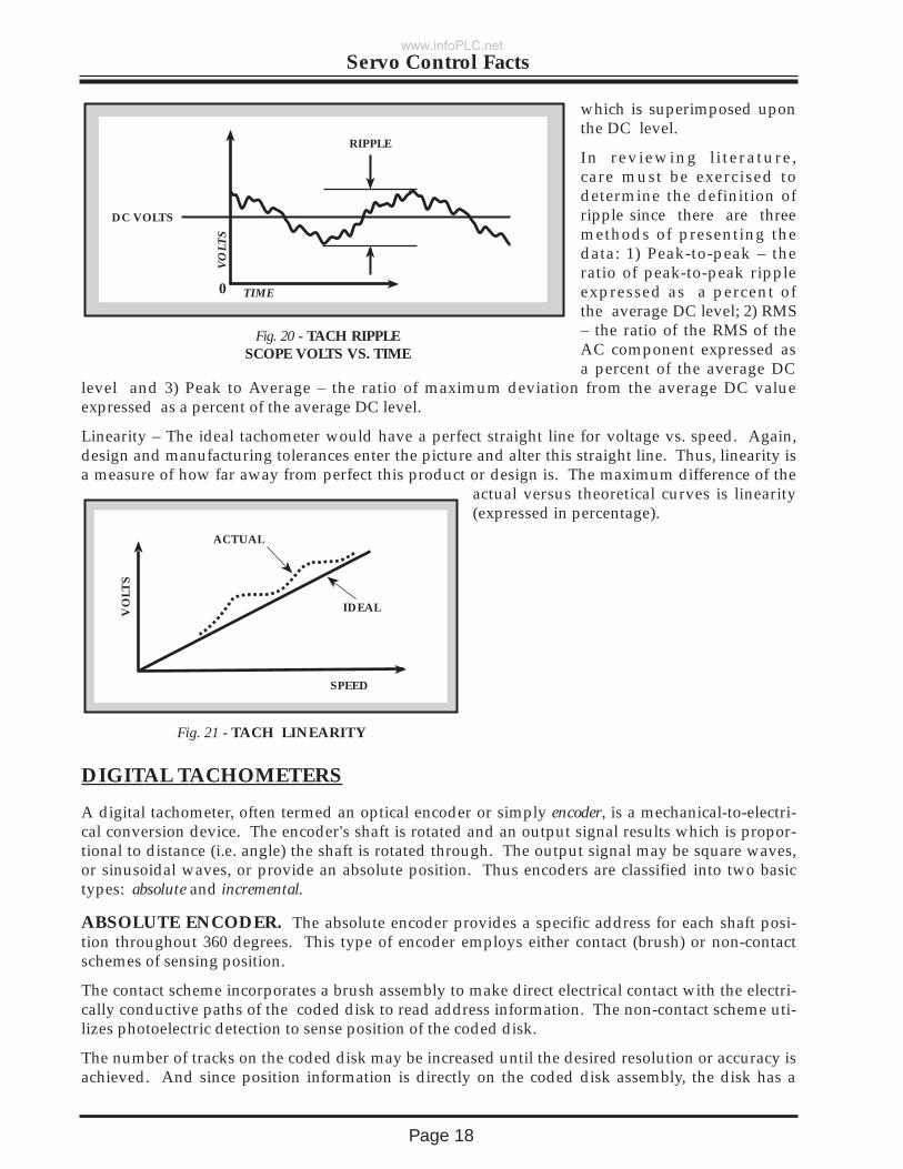
which is superimposed uponthe DC level.
In reviewing literature,care must be exercised todetermine the definition ofripple since there are threemethods of presenting thedata: 1) Peak-to-peak – theratio of peak-to-peak rippleexpressed as a percent ofthe average DC level; 2) RMS– the ratio of the RMS of theAC component expressed asa percent of the average DC
level and 3) Peak to Average – the ratio of maximum deviation from the average DC valueexpressed as a percent of the average DC level.
Linearity – The ideal tachometer would have a perfect straight line for voltage vs. speed. Again,design and manufacturing tolerances enter the picture and alter this straight line. Thus, linearity isa measure of how far away from perfect this product or design is. The maximum difference of the
actual versus theoretical curves is linearity(expressed in percentage).
RIPPLE
DC VOLTS
0
Fig. 20 - TACH RIPPLESCOPE VOLTS VS. TIME
TIME
VO
LTS
ACTUAL
IDEAL
SPEED
VO
LTS
Fig. 21 - TACH LINEARITY
DIGITAL TACHOMETERS
A digital tachometer, often termed an optical encoder or simply encoder, is a mechanical-to-electri-cal conversion device. The encoder's shaft is rotated and an output signal results which is propor-tional to distance (i.e. angle) the shaft is rotated through. The output signal may be square waves,or sinusoidal waves, or provide an absolute position. Thus encoders are classified into two basictypes: absolute and incremental.
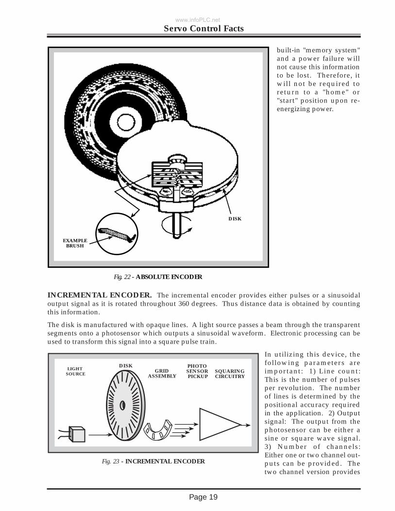
ABSOLUTE ENCODER. The absolute encoder provides a specific address for each shaft posi-tion throughout 360 degrees. This type of encoder employs either contact (brush) or non-contactschemes of sensing position.
The contact scheme incorporates a brush assembly to make direct electrical contact with the electri-cally conductive paths of the coded disk to read address information. The non-contact scheme uti-lizes photoelectric detection to sense position of the coded disk.
The number of tracks on the coded disk may be increased until the desired resolution or accuracy isachieved. And since position information is directly on the coded disk assembly, the disk has a
www.infoPLC.net
Page 19
Servo Control Facts
built-in "memory system"and a power failure willnot cause this informationto be lost. Therefore, itwill not be required toreturn to a "home" or"start" position upon re-energizing power.
EXAMPLEBRUSH
DISK
Fig. 22 - ABSOLUTE ENCODER
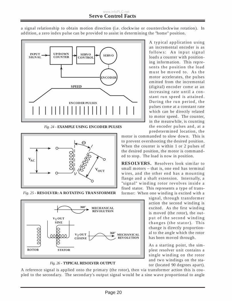
INCREMENTAL ENCODER. The incremental encoder provides either pulses or a sinusoidaloutput signal as it is rotated throughout 360 degrees. Thus distance data is obtained by countingthis information.
The disk is manufactured with opaque lines. A light source passes a beam through the transparentsegments onto a photosensor which outputs a sinusoidal waveform. Electronic processing can beused to transform this signal into a square pulse train.
In utilizing this device, thefollowing parameters areimportant: 1) Line count:This is the number of pulsesper revolution. The numberof lines is determined by thepositional accuracy requiredin the application. 2) Outputsignal: The output from thephotosensor can be either asine or square wave signal.3) Number of channels:Either one or two channel out-puts can be provided. Thetwo channel version provides
LIGHT SOURCE
DISKGRID
ASSEMBLY
PHOTOSENSOR PICKUP
SQUARINGCIRCUITRY
Fig. 23 - INCREMENTAL ENCODER
www.infoPLC.net
Page 20
Servo Control Facts
a signal relationship to obtain motion direction (i.e. clockwise or counterclockwise rotation). Inaddition, a zero index pulse can be provided to assist in determining the "home" position.
A typical application usingan incremental encoder is asfollows: An input signalloads a counter with position-ing information. This repre-sents the position the loadmust be moved to. As themotor accelerates, the pulsesemitted from the incremental(digital) encoder come at anincreasing rate until a con-stant run speed is attained.During the run period, thepulses come at a constant ratewhich can be directly relatedto motor speed. The counter,in the meanwhile, is countingthe encoder pulses and, at apredetermined location, the
motor is commanded to slow down. This isto prevent overshooting the desired position.When the counter is within 1 or 2 pulses ofthe desired position, the motor is command-ed to stop. The load is now in position.
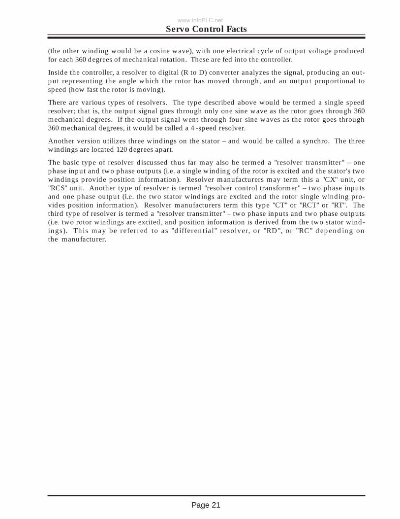
RESOLVERS. Resolvers look similar tosmall motors – that is, one end has terminalwires, and the other end has a mountingflange and a shaft extension. Internally, a"signal" winding rotor revolves inside afixed stator. This represents a type of trans-former: When one winding is excited with a
signal, through transformeraction the second winding isexcited. As the first windingis moved (the rotor), the out-put of the second windingchanges (the stator). Thischange is directly proportion-al to the angle which the rotorhas been moved through.
As a starting point, the sim-plest resolver unit contains asingle winding on the rotorand two windings on the sta-tor (located 90 degrees apart).
A reference signal is applied onto the primary (the rotor), then via transformer action this is cou-pled to the secondary. The secondary's output signal would be a sine wave proportional to angle
VAC
VOUT
Fig. 25 - RESOLVER: A ROTATING TRANSFORMER
SPEED
INPUTSIGNAL
UP/DOWNCOUNTER
SERVOCONTROL
SERVO
ENCODER
ENCODER PULSES
Fig. 24 - EXAMPLE USING ENCODER PULSES
MECHANICAL REVOLUTION
360°
MECHANICAL REVOLUTION
ROTOR STATOR
V1 OUTSINE
Fig. 26 - TYPICAL RESOLVER OUTPUT
V2 OUTCOSINE
360°
www.infoPLC.net
Page 21
Servo Control Facts
(the other winding would be a cosine wave), with one electrical cycle of output voltage producedfor each 360 degrees of mechanical rotation. These are fed into the controller.
Inside the controller, a resolver to digital (R to D) converter analyzes the signal, producing an out-put representing the angle which the rotor has moved through, and an output proportional tospeed (how fast the rotor is moving).
There are various types of resolvers. The type described above would be termed a single speedresolver; that is, the output signal goes through only one sine wave as the rotor goes through 360mechanical degrees. If the output signal went through four sine waves as the rotor goes through360 mechanical degrees, it would be called a 4 -speed resolver.
Another version utilizes three windings on the stator – and would be called a synchro. The threewindings are located 120 degrees apart.
The basic type of resolver discussed thus far may also be termed a "resolver transmitter" – onephase input and two phase outputs (i.e. a single winding of the rotor is excited and the stator's twowindings provide position information). Resolver manufacturers may term this a "CX" unit, or"RCS" unit. Another type of resolver is termed "resolver control transformer" – two phase inputsand one phase output (i.e. the two stator windings are excited and the rotor single winding pro-vides position information). Resolver manufacturers term this type "CT" or "RCT" or "RT". Thethird type of resolver is termed a "resolver transmitter" – two phase inputs and two phase outputs(i.e. two rotor windings are excited, and position information is derived from the two stator wind-ings). This may be referred to as "differential" resolver, or "RD", or "RC" depending onthe manufacturer.
www.infoPLC.net
Page 22
Servo Control Facts
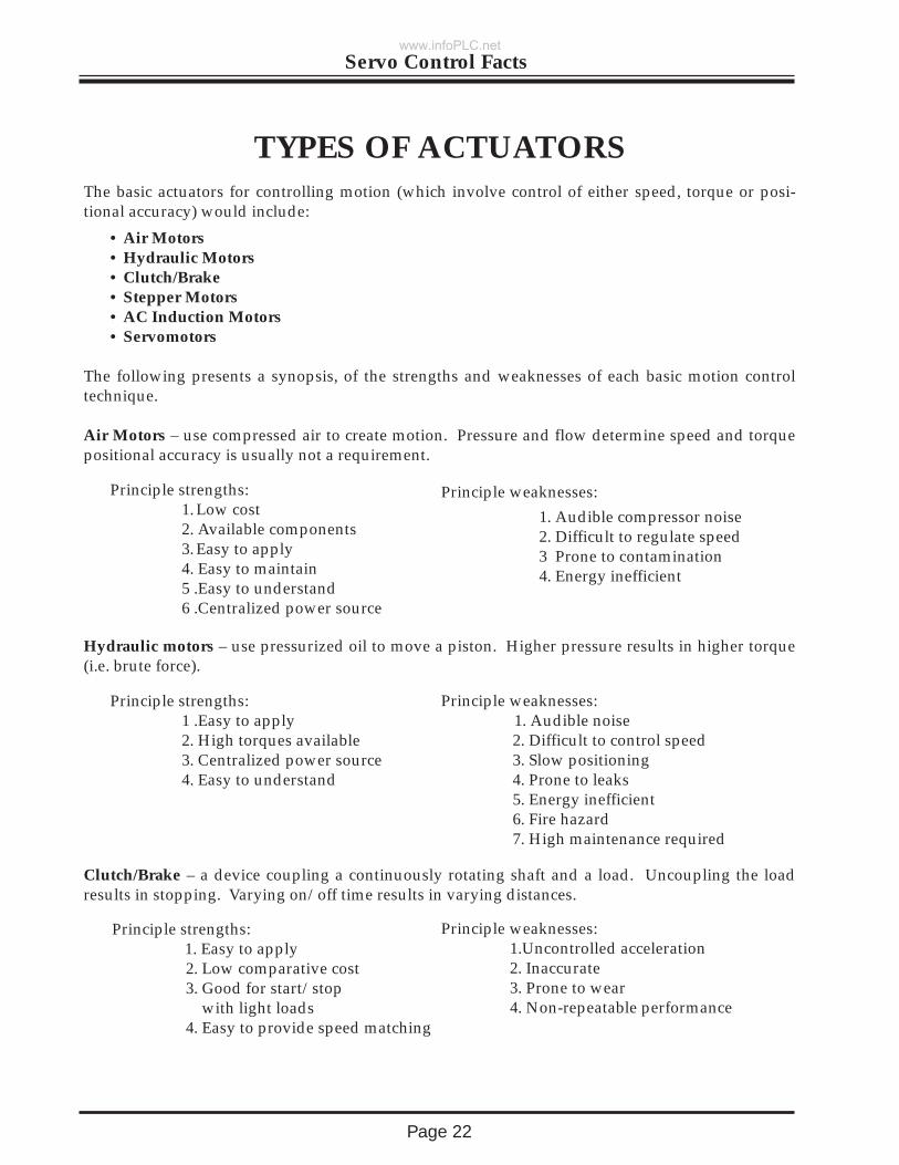
The basic actuators for controlling motion (which involve control of either speed, torque or posi-tional accuracy) would include:
• Air Motors• Hydraulic Motors• Clutch/Brake• Stepper Motors• AC Induction Motors• Servomotors
The following presents a synopsis, of the strengths and weaknesses of each basic motion controltechnique.
Air Motors – use compressed air to create motion. Pressure and flow determine speed and torquepositional accuracy is usually not a requirement.
Principle strengths:1. Low cost2. Available components3. Easy to apply4. Easy to maintain5 .Easy to understand6 .Centralized power source
Hydraulic motors – use pressurized oil to move a piston. Higher pressure results in higher torque(i.e. brute force).
Principle strengths:1 .Easy to apply2. High torques available3. Centralized power source4. Easy to understand
Clutch/Brake – a device coupling a continuously rotating shaft and a load. Uncoupling the loadresults in stopping. Varying on/off time results in varying distances.
Principle strengths: 1. Easy to apply2. Low comparative cost3. Good for start/stop
with light loads4. Easy to provide speed matching
Principle weaknesses:
1. Audible compressor noise2. Difficult to regulate speed3 Prone to contamination4. Energy inefficient
TYPES OF ACTUATORS
Principle weaknesses:1. Audible noise2. Difficult to control speed3. Slow positioning4. Prone to leaks5. Energy inefficient6. Fire hazard7. High maintenance required
Principle weaknesses:1.Uncontrolled acceleration2. Inaccurate3. Prone to wear4. Non-repeatable performance
www.infoPLC.net
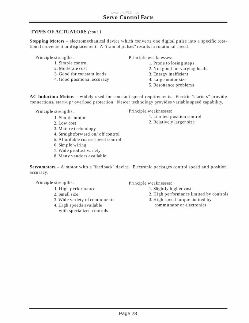
Stepping Motors – electromechanical device which converts one digital pulse into a specific rota-tional movement or displacement. A "train of pulses" results in rotational speed.
Principle strengths: 1. Simple control2. Moderate cost3. Good for constant loads4. Good positional accuracy
AC Induction Motors – widely used for constant speed requirements. Electric "starters" provideconnections/start-up/overload protection. Newer technology provides variable speed capability.
Principle strengths:1. Simple motor2. Low cost3. Mature technology4. Straightforward on/off control5. Affordable coarse speed control6 .Simple wiring 7. Wide product variety8. Many vendors available
Servomotors – A motor with a "feedback" device. Electronic packages control speed and positionaccuracy.
Principle strengths:1. High performance2. Small size3. Wide variety of components4. High speeds available
with specialized controls
Page 23
Servo Control Facts
Principle weaknesses:1. Prone to losing steps 2. Not good for varying loads3. Energy inefficient4. Large motor size5. Resonance problems
Principle weaknesses:1. Limited position control2. Relatively larger size
Principle weaknesses:1. Slightly higher cost2. High performance limited by controls3. High speed torque limited by
commutator or electronics
TYPES OF ACTUATORS (cont.)
www.infoPLC.net
BALDOR ELECTRIC COMPANY5711 South 7th Street
Fort Smith, Arkansas 72901(501) 646-4711
Fax (501) 648-5792
`3/94 5M CMc
www.infoPLC.net