servo motor vi fortuna serie 6
TRANSCRIPT

1) FOR AT MOST USE WITH EASINESS,PLEASE CERTAINLY READ THIS MANUALBEFORE STARTING USE.
2) KEEP THIS MANUAL IN SAFE PLACE FOR REFERENCE WHEN THE MACHINE BREAKS DOWN.
MMEEEE--009911220011
USER’’S MANUALPARTS BOOK
FORTUNAseries 6
R
SSuunnSSttaarr CCOO..,, LLTTDD..
Version 1.0
IISSOO 99000011 CCeerrttiiffiiccaattiioonn ooff QQuuaalliittyy SSyysstteemm

Best Quality
Best Price
Best Service
SSUUNNSSTTAARR CCOO..,, LLTTDD..R
1. Thank you for purchasing our product. Based on the rich expertise andexperience accumulated in industrial sewing machine production, SUNSTARwill manufacture industrial sewing machines, which deliver more diversefunctions, high performance, powerful operation, enhanced durability, andmore sophisticated design to meet a number of user’s needs.
2. Please read this user’s manual thoroughly before using the machine. Makesure to properly use the machine to enjoy its full performance.
3. The specifications of the machine are subject to change, aimed to enhanceproduct performance, without prior notice.
4. This product is designed, manufactured, and sold as an industrial sewingmachine. It should not be used for other than industrial purpose.


USER’SMANUAL

1. Safety instruction ··························6
2. Precautions before use ························8
3. Locating and using parts of the controller box ··············10
4. Installation·····························111) Mounting your Servo Motor on the table ······················11
2) Assembling the belt cover and adjusting the belt tension ···············12
3) Mounting and adjusting the foot-lift solenoid ····················13
4) Mounting the position sensor (Synchronizer) and setting the film ············14
5) How to equip and adjust a built-in location detector(synchronizer) ···········16
6) Mounting the Program Unit(P/U) ·························18
7) An example of installing the SunStar sewing machine ················19
5. Wiring and grounding ························201) Specification of the power plug ··························20
2) Specification of electric current in wiring of power plug ················20
3) Name and description on the outside connector of control box·············21
6. Connection the earth wire of the sewing machine and motor········22
7. Things to be checked after installation ·················22
8. Program unit part names and method of use ··············231) Program unit part names ····························23
2) Program Unit Method of Use···························23
3) Start and End Backtack Stitch Correction Method ··················34
4) Method of Use: Inertia Tuning Function ······················37
5) Advanced Pattern Sewing Functions ·······················38
6) Use of Detailed TPM(Total Production Maintenance) Functions ············40
9. Fortuna series software method of use·················431) Basic Functions of the Fortuna Series Software ··················43
2) Fortuna Series Software Specific Parameters ···················44
3) Method of Use and Explanations for Specific Items of the Parameter ··········57
4) Thread Trimming Sequence Function Method of Use (Items no. 54, 55, 56 of Group B) ··61
10. Breakdown and troubleshooting ···················67
11. How to place for controller······················68
※ PARTS BOOK···························69
CCOONNTTEENNTTSS

6
Be sure to read and keep in mind the following instructions before you install and usethr FORTUNA SERVO MOTOR.
1) Use and PurposeThis product is designed, manufactured, and sold as an industrial sewing machine. It should not be used forother than industrial purpose.
2) Working Environment① Power Source•It is desirable that voltage of the power source be kept within the range of ±10% of the rated voltage.•It is desirable that frequency of the power source be kept within the rage of ±10% of the rated frequency.
(50/60)•The SERVO MOTOR can be expected to work normaly only in case the foregoing things are kept.
② Electromagnetic Noise•It is desirable that those equipments causing strong electromagnetic field or high frequency not use the
same electrical outlet as this on and stay away from it.③ Temperature and Humidity•Keep the ambient temperature above 5 degrees and below 40 degrees Centigrade. •Never use it outdoors and avoid direct ray of light.•Keep it away from an hot object like a stove.•Keep the ambient humidity above 30% and below 95%.
④ Never use it near gases and explosives.⑤ Do not use it at a spot located 1,000m or higer above sea-level.⑥ Keep the storage temperature higher than 25 degrees below zero and lower than 55 degrees Centigrade when
not in use.
3) InstallationFollow the instruction carefully when installing it.① Be sure to start installing it after pulling the power plug off the outlet.② Fix the cable so that it may not move, and do not allow the moving parts like belts to be interfered with.(keep
distance of at least 25mm from them.)③ Be sure to have the Controller, the Motor and the sewing Machine grounded.④ Be sure that the voltage of power source fits the specification of the Controller before the power is on⑤ Be sure to use Safety Extra Low Voltage when an extra item or an accessory is fitted into the Controller.
4) Disassembly① Indisassembling it, be sure to wait at least 360 seconds before taking any action after pulling the plug off the
power source after turning it off.② When pulling off the plug from the power source, be sure to hole the plug itself instead of the wire connected
to the plug.
SAFETY INSTRUCTION

5) Service and Maintenance① Make sure that service and maintenance are carried out by a skilled technician.② Never try to operate with the Motor and the Controller open.③ When inserting a thread into or touching the machine, be sure to turn the power off and step down from the
platform.④ Be sure to use standard products specified for replacement of parts.
6) Other Safety Instructions① Tack care not to let your fingers touch any moving parts including belts.② In case of remodelling or fitting of additional device, be sure to follow safety standards and do not ever try to
go ahead based on your own judgments.③ Do not try to operate with the safety device removed.④ Take care not to let water or coffee or something like those admitted into the Controller or the Motor.⑤ Never drop the Controller or the Motor to the ground.
The instructions presented above are for the safer and more proper operation of the Fortuna ServoMotor. Ignoring such instructions could cause damage to the machine or physical injury of the user.Please follow all the instructions when operating the machine.
7

8
PRECAUTIONS BEFORE USE
1. Do not turn on the power while stepping on the pedal. 2. Turn off the power when leaving the servomotor overnight.
3. Turn off the power when servicing the servomotor or changingthe needle.
4. Be sure to keep the servomotor securely grouned.
5. Do not connect multiple servomotor power plugs to the samepower strip.
6. Install the servomotor away from noise sources, such as high-frequency equipments and welding machines.
7. Avoid electrical shock when servicing the controller box. (Wait for 6minutes before opening the cover after turning off the power.)
8. When an error message “Er”sppears on the digital display,take a note of the “Er”code, and then turn on and off beforeresuming operation(Contact the local dealer if “Er” messagepersists on the display)

9
9. Adjust the belt tension to the optimum level.
Belt-tension adjustment shouldbe performed after the motor ismounted on the table : First,loosen both the upper andlower anchoring bolts(①, ② ). The belt tension will then beadjusted by the weight ofservo motor itself. Fasten bothanchoring bolts.
10. Clean it every two or three weeks so that no dirt or a dirtysubstance may be piled up.
11. When replacing the fuse, use a standard item, opening thecover as shown in the diagram.
12. Make the length of the cable connected with an outside partslike stand-up pedal as short as possible.
①
②
250[V]/6.3[A]
250[V]/1[A]
F2. F3
F1Digital board
Filter board

Control box right sideControl box left side
10
LOCATING AND USING PARTS OF THE CONTROLLER BOX1) Left and right side of control box
2) Rear panel
① Caution
② Motor③ AC INPUT
Hazardous voltage will cause injury.Be sure to wait at least 360 seconds beforeopening this cover after turn off main switch andunplug power cord.
고압 전류에 의해 감전될 수 있으므로 커버를 열 때는 전원을 내리고 전원 플러그를 뽑고 나서 360초간기다린 후 여십시오.
WARNING경 고
Motor Encoder Connector
Motor Power Connector
Main AC Power
12V LEC lighting connector (orange color)
knee lifting solenoid (green color)
Basic solenoid connector
Program unit connector (white color)
Resolver connector (Black color)
②
③ ①
11
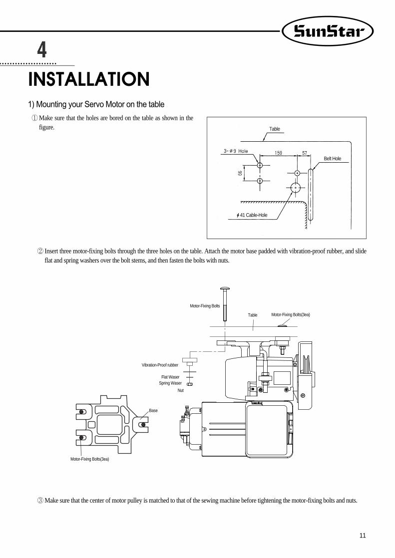
1) Mounting your Servo Motor on the table
② Insert three motor-fixing bolts through the three holes on the table. Attach the motor base padded with vibration-proof rubber, and slideflat and spring washers over the bolt stems, and then fasten the bolts with nuts.
③Make sure that the center of motor pulley is matched to that of the sewing machine before tightening the motor-fixing bolts and nuts.
①Make sure that the holes are bored on the table as shown in thefigure.
INSTALLATION
Table
Belt Hole
ф41 Cable-Hole
Motor-Fixing Bolts
Motor-Fixing Bolts(3ea)
Motor-Fixing Bolts(3ea)
Vibration-Proof rubber
Table
Flat WaserSpring Waser
Nut
Base

12
2) Assembling the belt cover and adjusting the belttension
(1) Belt cover assembling procedure① Upon the completion of the motor mounting, bring the two
pulleys of motor and sewing machine closer to each other, by
pulling back the sewing machine. You can then mount the belt
easily as shown in the figure.
② Place the belt cover ‘B’, making sure that the belt cover does
not contact the belt, and then fasten the cover with the fixing
screw.
(2) Adjusting the belt tension① Optimum Tension Level:The optimum tention level is
achieved when the belt is pushed by 5-10mm when the top
surface portion of the belt at about 30-50mm above the tabletip
is pressed by a finger with a force of~1m/sec2 or 1 Newton.
② Adjusting the Tension Level:If the tension level is out of the
optimum range, adjust the tension as follows. First, loosen both
the upper and lower nuts for the anchor bolt, letting the belt be
stretched by the motor weight itself. Second, tighten the upper
nut only to the extent that the motor does not move. Third,
fasten the bottom nut tightly so that the motor is securely fixed.
Controller Box
Upper Nut for the Anchor Bolt
5~10mm
30~50mm
Lower Nut for the Anchor Bolt
→←
Belt Cover “A”
Belt Cover “B”Belt
Belt Guide Fixing Screw
Belt Cover Fixing Screw
Belt Guide
Pulley
Belt GuideFixingScrew
Warning
Do not remove the belt cover.If a finger slips into the belt, it might be broken orcut off.
Warning
Make sure that the power is off beforeassembly.

13
3) Mounting and adjusting the foot-lift solenoid
(1) SunStar KM-250 Model① First, assemble a panel for the attachment of presser foot
solenoid on the back of KM-250.
② Attach the presser foot solenoid to a bracket “A”.
③ Attach the bracket “A”with the presser foot solenoid to the
panel above.
④ Attch a crank to a solenoid shaft and then connect it to a
sewing machine.
⑤ Place a cover on the solenoid.
(2) Adjusting the stroke(Gap) of the automatic foot-lift
solenoid① Check point
Check to make sure that the stroke-adjusting screw islocated at the center of the solenoid axis, i.e., the solenoidshould be assembled in parallel with the bottom surface ofthe table. If the solenoid is not in paralle, make anadjustment so that the screw is in parallel with the center ofthe solenoid axis using the connection link-fixing screw.
② Adjusting Procedure
The verical travel distance of the presser foot can be adjusted by
the stroke-adjusting screw. First, Loosen the two fixing screws,
and adjsut the vertical stroke using the stroke-adjusting screw.
loosening and tightening the stroke-adjusting screw will decrease
and increase the verical stroke of the presser foot respectively.
After the adjustment, fasten the fixing screw tightly.
Oil Pan
Fixing NutsSolenoid Axis
Stroke-Adjusting Screw
Connection Link-Fixing Screw
※KM-250 Rear Panel
Solenoid Bracket A Cover for Foot-Lift Solenoid

14
4) Mounting the position sensor (Synchronizer) andsetting the film
(1) Mounting the position sensor(Synchronizer)① SunStar thread-cutting sewing machine.
All SunStar thread-cutting sewing machines are equippedwith a position sensor. Users, therefore, are required to theadjust the film position, if necessary, as shown in the figure.
② All other sewing machines(including other manufacturers’ brands)
First, attach the position sensor-mounting adapter to the upper shaft of the sewing machine. Second, attach the position sensor-fixingplate to the body of the sewing machine as shown below in the figure. Third, secure the position sensor to the adapter with the fixingscrews.
L Wrency
Pulley
Synchro shaft-fixing screw(2)
Synchro shaft
Photo film(Adjusted left and right)
Photo INTERRUPT
COVER
Upper Shaft
P.C.B Holder
Adapter
Position Sensor-Fixing Bolts
Position Sensor
Cable
Position Sensor-Fixing Plate(Type B)
Nylon Cable TieFiixing Bolt for PositionSensor-Fixing Plate
Position Sensor-Fixing Plate(Type A)
Pulley

15
(2) Adjusting the film of the position sensor① Assemble the films and position sensor in the order as shown
in the figure.
② Upon the completion of the assembling, position the needle shaft tight at the rising point from the lowest needle position by manually
rotating the pulley. Loosen the film-fixing screw, and adjust the DOWN film so that the film-adjsting line and the sensor housing
calibration line are matched. Tighten the film-fixing screw just to the extent that the film can not be rotated. Likewise, position the thread
take-up at the highest position. Loosen the film-fixing screw, and adjust the UP film as shown in the figure, while using caution not to
move the DOWN film which is already adjusted earlier. Tighten the adjusted film with the fixing screw.
(3) Adjustion the films of reverse rotation sewing machines※For reverse-rotation sewing machines, the film-adjusting lines located at right edge of the “UP”and “DOWN”film should be matched to
the center line of the sensor.
Fixing WasherFixing Bushing
Film-Fixing ScrewPosition Sensor Shaft
Fixing Nut Fixing Nut
Fixing NutFixing Nut
Setting Position
Setting Position
Sensor Calibration Line
Sensor Calibration Line
Film-Adjusting Line
Film-Adjusting Line(Reverse Rotation)
Sensor Housing
Sensor Housing
The highest positionof take-up lever
The highest positionof take-up lever
Up Film Adjustment
Up Film Adjustment
Down Film Adjustment
Down Film Adjustment
2mm turning aroundfrom the lowestposition of needle bar
2m turning aroundfrom the lowestposition of needle bar
Caution
After adjustment the film of the position detector, be sure to rotate the motor for 3~5 seconds by pedalling sothat the Controller may remember location of the film.

16
5) How to equip and adjust a built-in locationdetector(synchronizer)
(1) How to equip the built-in location detector
(synchronizer) In case of a SunStar thread trimmer
When a built-in location detector(synchronizer) for thesewing machine with the SunStar thread trimmer isequipped, all that the users need to do is to simply adjust thelocation of magnetic for detection according to their needs.
Locate detector(synchronizer)
Position magnetic up
UpperShaft
Position magnetic down
Position magnetic up
Sewing machinepulley
Locate detector(synchronizer)
Positionmagnetic down
Sewing machine

17
(2) How to adjust the magnet of the location detector① Assemble the detector in order following the pictures.
② Once assembling is completed, power the controller on and step on the pedal. At this time, make sure that the needle moves up and down.
Stop the needle at a desired location by moving the magnet back and forth along the location where the needle stops.
(3) How to adjust a location detector in case of a reverse rotation sewing machine※It is the same as that used for the normal rotation direction
Locate detector(synchronizer)
Normal rotationdirection
Reverse rotationdirection
Reverse rotationdirection
Normal rotationdirection
The highest positionof take-up lever
The highest positionof take-up lever
Locate detector(synchronizer)
Locate detector(synchronizer)
2mm turning aroundfrom the lowestposition of needle bar
2mm turning aroundfrom the lowestposition of needle bar
Caution
After adjusting a location detector, rotate the motor by stepping on the pedal for 3~5 seconds so that acontroller can remember the location.

18
6) Mounting the Program Unit(P/U)
(1) SunStar KM-235 Sewing MachineFirst, attach the P/U bracket to the P/U using three fixing screws
and a supporting bolt with nut attached on it as shown in the
figure. Second, securely attach the P/U to the head of the sewing
machine using two fixing screws and washers, keeping a 3~4mm
distance between the bottom surface of the nut and the base of the
supporting bolt.
(2) Other SunStar thread-machineFirst, attach the P/U bracket to the P/U using the four fixing screws. Second, attach the P/U to the main body of the sewing machine using the
three bracket-fixing screws as shown in the figure.
Program Unit
Program UnitP/U Bracket
P/U Bracket-FixingScrew(3)
Caution
Fix the cable using the cable tie so that cable is not in the way of the belt.

19
7) An example of installing the SunStar sewing machine

20
1) Specification of the power plug
(1) Single phase 200V~240V
(2) Three phase 200V~240V
(3) Three phase 380V
※Be sure to connect Protective Earth
2) Specification of electric current in wiring of power plugBe sure to use wiring materials which can stand electric current of higher than 15A.
WIRING AND GROUNDING
220V
220V
380V
EARTHV
EARTHV
EARTHV
Switch Box
Control Box
Control Box
Control Box
Switch Box
Switch Box

21
3) Name and description on the outside connector of control box
① Standard solenoid connector
[ Shape of pin ] [ No. of pin ]
11, 12:Button for manual back-tack operation
1, 5:Back Tack Solenoid2, 6:Thread-Cutting Solenoid3, 7:Wiper Solenoid
② Foot-lift solenoid
Connector Color:Green
Foot-Lift Solenoid Switch
Foot-Lift Solenoid

22
MethodConnect the motor and sewing machine using the ground wire(green, green/yellow) as shown in the figure. Make sure that thefactory-connected ground wire between the controller box andmotor is securely in place.
CONNECTION THE EARTH WIRE OF THE SEWING MACHINE AND MOTOR
1) Before the power is on...①Make sure that the incoming voltage is in accordance with that shown in the name plate of the Control box.② Check whether the following connectors are connected.
•Connector for incoming AC power source•Connector for motor power•Connector for motor encoder•Connector for pedal•Connector for position detector•Connector for others (option, knee-lift, program unit etc.)
③ Check to see whether the belts are in touch with the wiring.④ Check the tensile strength of the belts.⑤ Check to see the fixing nuts for pulley are tightly fastened.
2) After the power is on...① Check whether the lamp for the position detector is on. (Except in the case of built-in position detector)② Check whether the program unit is working.③ Check the direction of rotation of the Sewing Machine.
•In case the direction of rotation is not right, action shall be taken to change set it right, referring to “the methods of changing theprogram and the list of changing functions”(N. 65 in Group “A”)
④ Check to see whether there are abnormal heat, smell or noise nearby.•In case there are, turn the power off and call our regional office.
THINGS TO BE CHECKED AFTER INSTALLATION
Caution
Failure to ground the motor can cause abnormaloperations, such as overspeed rotation or unwantedstitching.

23
1) Program unit part names
2) Program Unit Method of Use
(1) 4-Digit Displayer and 2-Digit Displayer Functions and Method of UseA. 4-Digit Displayer and 2-Digit Displayer Functions
PROGRAM UNIT PART NAMES AND METHOD OF USE
①When you turn the power on, you will see a screen as shown in the figure.The 4-digit displayer shows the start and end B/T sewing and the 2-digitdisplayer shows the current abbreviation for the letters or numbers shown inthe 4-digit displayer (bt: the abbreviation for back tack),
<Initializing screen>
<Example of error detection>
<Example of selection of number 2 item in Group A>
② The 4-digit displayer shows the error number for each type of errordiscovered and also shows the programmed value after it has beenprogrammed. The 2-digit displayer shows the number of the parameterspecific item's content or name which is shown in the 4-digit displayer.
2--Digit Displayer
Sunstar Logo
4-Digit Displayer
1/2 Stitch Button
Button for Program Change
Button for Counter Use after Counter Programming
Button to use Edge Sensor Selection after Edge Sensor Programming
Button to Save Program Changes
Pattern Work Selection Button
Start B/T Selection Button
End B/T Selection Button
Button to Select Needle Plate Location When Machine Stops
Button to Select Presser Foot-lift Location When Machine Stops
Thread-trimmer and Wiper Selection
Button to Change the Sewing Speed Installation
Pattern Work Connecting Button
Constant Sewing Speed Selection Button
Caution
The 4-digit displayer and 2-digit displayer show the current condition. Therefore the user should always check itbefore using the machine.

24
B. Method of Use: 4-Digit Displayer and 2-Digit Displayera. Method to change the start and end B/T stitch numbers
In order to change the start B/T stitch numbers which is programmed when youfirst purchase this machine, you must use the , buttons. If you want to
change the end B/T stitch numbers, you must use the , buttons.•The program range is from 0 to 9.
(Ex: How the screen looks when changing both start and end B/T stitchnumbers to 4).
b. Method to check or change the specifics of the parameter
(2) Method of Use: Stitch Button Function
① Press the button and as you press it, also press the button. Thenyou can either check or change the programming items for the parameter ofgroup A. (A group: , B group: , C group: , D group: )※ Users should turn the machine off to select B, C, or D group. While
pressing the button, turn the power switch on. The screen will bechanged to the initial screen after showing the "PrEn" message. Then, theusers can select B, C, or D group by pressing B, C, or D button whileholding program button.
②You can move to the parameter item you want with the and buttons. The parameter item number will appear in the 2-digit displayer andthe wanted value will appear in the 4-digit displayer.
(Ex) Screen showing the maximum speed limit preset in the item 2 of A group)
③After using the (increase) button and (decrease) button to choose
the value you want, press the (Enter) button and save the value you
chose. (Ex: Reducing the maximum sewing speed limit from 4000RPM to
3000RPM).
④ After saving, press the button and go back to the initial screen.
①When necessary, make stitches by pressing the stitch ( ) button.
②When the needle plate makes a down stop, shortly press the stitch ( ) button once and the needle plate will make an up stop.
And when the needle plate makes an up stop, shortly press the stitch ( ) button once and the needle plate will make a down stop.
Caution
•Be aware that if you don't press after changing the programmed value for the parameter item, the value will not be saved.•When the B, C, or D group selection is completed, users should turn off the machine first and restart to secure the selected
group. •If the user changes the programmed value from the parameter specifics carelessly, the user may cause break down or physical
damage to the machine. The user must therefore be well-trained before changing the parameter group.
Caution
Be aware that if you are continuously pressing the ( ) button, the machine will keep on moving at the stitch
( ) speed.

25
(3) Method of Use: Start B/T Button
This button is used when the user wants to prevent threads from loosening at the end of the sewing work. If the user presses this buttonin sequence, the location on the lights will change. This button offers the following three functions.
Using the A, B buttons in the 4-digit displayer, the user can program the B/T number of stitches he/she wants.
When sewing starts, B/Tsewing does not operate.
When sewing starts, B/Tsewing is operated withthe
button.
When sewing starts, B/Tsewing is operated withthe
button.
(4) Method of use: End B/T Button
This button is used when the user wants to prevent threads from loosening at the end of the sewing work. If the user presses this buttonin sequence, the location on the lights will change. This button offers the following three functions.
Using the C, D buttons in the 4-digit displayer, the user can program the B/T number of stitches he wants.
When sewing ends, B/Tsewing does not operate.
When sewing ends, B/Tsewing can be operatedwith the
button.
When sewing ends, B/Tsewing can be operatedwith the
button.
(5) Method of Use: The Needle Plate Position Selection Button When the Sewing Machine Stops
When the user turns the power on, one of the up stop or down stop lights in the program unit panel needle plate is always left on. Theuser can change the stop location by pressing the button.
When machine stops while sewing, theneedle plate makes an up stop.
When machine stops while sewing, theneedle plate makes a down stop.
Caution
Be aware that if the start B/T stitch is set to '0' in the 4-digit displayer, the start B/T sewing is impossible.
Caution
Be aware that if the end B/T stitch is set to '0' in the 4-digit displayer, the start B/T sewing is impossible.

26
(6) Method of Use: The Presser Foot-lift Location Selection Button When the Sewing Machine Stops
When the user turns the power on, one of the up stop or down stop lights in the program unit panel pressser foot-lift is always left on.The user can change the stop location by pressing the button.
When the machine stops while sewing, thepresser foot-lift stops at the top.
When the machine stops while sewing, thepresser foot-lift stops at the bottom.
(7) Method of Use: Automatic Thread Trimmer and Wiper Selection Buttons
These buttons offer the function of automatic trimming and wiping after sewing. By pressing these buttons in sequence, the user can useone of the following three functions. The light shows the function that is currently being used.
Automatic trimmer and wiperdo not operate
Only automatic trimmerfunction is operate
Both automatic trimmer andwiper operate
Caution
If the user uses the automatic up stop function of the presser foot-lift when the sewing machine stops while sewing, itmay cause damage to it because it has been left up for an unnecessarily long time. Be aware that to prevent thefoot-presser solenoid from being damaged, it is programmed to automatically come down when a certain amount oftime passes.
(8) How to use product counter and bobbin counter
To use the counter function, set the detailed functions under parameter B-Group.
① When product counter and bobbin counter are not used
②When product is setcounter function
③When is setbobbin counter function
Repeatedly press the ( ) button in the program unit to change the status of the lamp and functions as below.
How to set product counter and bobbin counterA. Set/clear product counter and bobbin counter using the button in the program unit
<When the lamp is off>
<When the lamp is on>
<When the lamp is flashing>

27
How to use detailed functions of product counter and bobbin counterA. How to use the detailed functions of product counter
To use the counter function, set the detailed functions beforehand.
② Set the parameter to select the type of product counter•1: Up counter •0: Down Counter ※ The default value is set at “1”.
B-36
③ Press the counter button to set the counter function. Press the button to check andset the detailed data of the counter.•Cn: The current counter amount •rn: The remaining amount •%: The progress •tn: Total target amount (Default: 100) ※ Press button repeatedly to see the above detailed data in order. The user may
set up the current counter amount (Cn) and the total target amount (tn) as desired.
④After the total target amount is set, use and to set the movements.<Set value of B-37>•0: When work is finished, the buzzer will go off and sewing may begin•1: When work is finished, the buzzer will go off and sewing may begin only when
the button is pressed•2: When work is finished, the buzzer will not go off and sewing may begin< Set value of B-38>•0: No returning to automatic initial value when counting is complete •1: Returning to automatic initial value when counting is complete
B-38B-37
① To use the product counter function, first set the value of the parameter (group B, item 35) as desired. •0: Set the external counter switch on •1: Set the automatic counter on after trimming※As the default value is set “0”, the counter will not run if there is no external counter
switch.
B-35
<The current amount>
<The remaining amount>
<The progress>
<Total target amount>
[ Caution ] When B-38 is set at “0”, the value will keep on going up/down even when counting is complete. The user will need to re-set thevalue of Cn to restart.
28
B. How to use the detailed functions of bobbin counterBobbin counter is designed to check the remaining amount of the lower thread. a. To use the counter, set detailed functions beforehand.
b. Detailed functions of bobbin counter
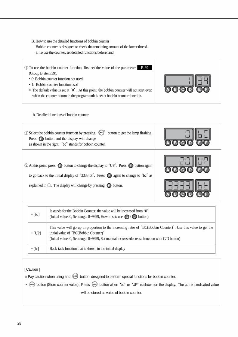
① To use the bobbin counter function, first set the value of the parameter (Group B, item 39). •0: Bobbin counter function not used •1: Bobbin counter function used※ The default value is set at “0”. At this point, the bobbin counter will not start even
when the counter button in the program unit is set at bobbin counter function.
B-39
① Select the bobbin counter function by pressing button to get the lamp flashing.Press button and the display will changeas shown in the right. “bc”stands for bobbin counter.
②At this point, press button to change the display to “UP”. Press button again
to go back to the initial display of “3333 bt”. Press again to change to “bc”as
explained in ①. The display will change by pressing button.
•[bc]
•[UP]
•[bt]
It stands for the Bobbin Counter; the value will be increased from “0”. (Initial value: 0, Set range: 0~9999, How to set: use / button)
This value will go up in proportion to the increasing ratio of “BC(Bobbin Counter)”. Use this value to get theinitial value of “BC(Bobbin Counter)”(Initial value: 0, Set range: 0~9999, Set manual increase/decrease function with C/D button)
Back-tack function that is shown in the initial display
[ Caution ]
※Pay caution when using and button, designed to perform special functions for bobbin counter.
• button (Store counter value) : Press button when “bc”or “UP”is shown on the display. The current indicated value
will be stored as value of bobbin counter.

29
c. Setting Bobbin Counter Functions
①When you start new sewing work, you must re-set the value of bobbin counter. Referto the following if you do not know your re-set value.•First move to “UP”display and use , button to change the value to “0”.•Replace old lower thread with the new one. The amount of the lower thread must be
consistent.•Begin sewing. The more you sew, the higher the value of “UP”will be.•Continue sewing until you run out of the lower thread.•When there is no lower thread left during sewing, press button to store the
counted value.•Before saving, subtract some 10~20 from the value in order to reflect the counted
value after the lower thread ran out.
②When the bobbin counter setting is complete, move to “bc”display.
③ The value of “BC(Bobbin Counter)” increases gradually when sewing begins aftercompleting set-up.
[ Caution ]※ Before using the bobbin counter function, move to “bc”display or initial display. If you start working from “UP”display, the
value of counter will go up.

30
d. When bobbin counter is complete
①Replace the old lower thread with the new one and start sewing, then the value of“BC(Bobbin Counter)” will go up gradually.
② Take note that the buzzer will go off when the value goes up, and the gap between thatvalue and setting value narrows under 20. This is to warn that there is little lowerthread left.
③ The value of Bobbin Counter is reached at setting value, the stitching will be stoppedand the buzzer will go off and the monitor will start blinking.
④ When sewing stops after counting is complete, use the following method to return.
•Press the button to change the value of “BC” to the “0” automatically.(AUTO CLEAR/PRESET)
[ Caution ]
※ To use the bobbin counter function, first set B-Group 39 to “1.”
※ Use button to change the display to set/clear the value of bobbin counter during sewing.
※ Wind the lower thread with consistency to ensure the proper use of bobbin counter functions. Counter functions may work
differently depending on lower thread and sewing conditions.

31
(9) Method of Use: Pattern Work Selection ButtonA. Method to Set Up the Pattern Work Function
This function is used when you need to continuously work on a sewing material. If thelight goes on after pressing the button, you can use the pattern sewing function.
B. Method of Use of Pattern Sewing Specific Functions
① Cautionary words when using the pattern function •Before using the pattern function, finish the trimming work and turn on the pattern switch light. •If the user presses the pattern switch twice when he/she is not using the pattern function, the light will go off and he/she will be
able to go back to normal sewing. However, if the pattern mode has not been completely finished, the pattern light will not gooff.
•The pattern function sewing speed will be the programmed speed. •The value set in each pattern mode is not erased when the power is turned off. Therefore, if you want to use the same pattern
again, press the same mode again to use it. However, if the program is initialized, all the formerly programmed information willbe erased and the user must reset the information again.
② Method of use: function
first press the button and select the pattern sewing function. Select the pattern you want and the light will go on the pattern you selected. If you press the button, the screen will change and you can use the stitches of
each side of the pattern you chose to program the value.< Method to program the value of each pattern side >•Method by using the , buttons -Inputting directly the number of stitch the user wants by using the buttons C and D.
This method is used when the user already knows the length of the stitches he/sheis choosing.
-Method using the pedal movement -This is a function used when the user does not know the stitch length and sews
directly to check the number of stitches for the pattern he/she wishes to program. Ifthe user presses on the pedal after the programming screen comes on, the pedal canprogram the number of stitches by using the accelerating and deceleratingcharacteristics through the pedal's sensors. The standard for choosing the numberof stitches here is slower than the normal sewing speed and the programmedpattern sewing speed.
-Method using the A button and 1/2 stitch button -This function is used when the user needs to make small adjustments at the end of
the pattern work. It allows the user to check and program the pattern length whilehe/she sews at a slow speed or sews half stitches.
P:When the AUTO light is off, the machinestops when the pedal is released whilesewing.
A:When the AUTO light is on, the machinewill finish sewing the pattern section even ifuser releases pedal while sewing.
<Screen showing thef programming ofstitch numbers for each side>
⇒
After programming is finished, press the button and save the set up value. Then press the
button. After the stitch numbers of each side disappear from the screen, you can start sewing with the programmed value in the pattern sewing function.
The pattern sewing speed is constant because it sews at a programmed speed not by theacceleration or deceleration of the pedal. If you press the pedal after pressing the button andsee the light blink, sewing will continue until it is finished even if you release the pedal.
Caution
•After setting each side of the stitches, the user must press the button to save the programmed value. •When the pattern has more than one side, the pattern work only operates for the number of stitches programmed
for each side.

32
③ Specific items of each pattern
A convenient pattern for straight sewing at constant speed for a definite length. Thesides can be set from 0 to 999 stitches.
A convenient pattern for repetitive 3-sided sewing. Each side can be set from 0 to 999stitches.
A convenient pattern for 4-sided sewing. Each side can be set from 0 to 999 stitches.(Used often in square sewing)
A convenient pattern when forward/backward sewing is needed continually.forward/backward sewing is possible 9 times. Also each side can be set from 0 to 999stitches.(This pattern is used for continuous work on back tags of leather belt rings).
A convenient pattern when the user wants to make many-sided patterns. The user canmake patterns of up to 20 sides. Each side can be set from 0~999 stitches.
Caution
•After programming the chain function and pressing the button, the set up value is saved.
•If you change the pattern program while sewing, it will sew with the new programmed pattern.
•If the last chain pattern is finished, it will automatically go to the first sewing pattern.
④ Method of Use:Chain function (pattern linking function)
•First press the button and select the pattern sewing function
•Next, press the button.
•If you press the button, the screen will change as the figure shows on the right.
You can change the number of chains with buttons , .•If you want to program the number of chains in the pattern you want, use buttons
and, to go to the item you want and press the pattern button.•At this time when you press the button , the screen is changed like the picture and
the screen for setting how many times you operate a desired pattern with a desirednumber is displayed.
•The performance frequency can be input by using button and . Input range: 1~250 times (standard: 1 time)
Example: No.1 pattern (5 times) → No.2 pattern (10 times) →‥‥
•After programming the chain numbers as explained above, press the button and
the change of value will be saved. Then press the button to come out from the
chain programming screen. •If you operate the programmed sewing work, the pattern with the blinking light is
the current work being done and the pattern with the light on continuously is the nextprogrammed pattern.
※If the user presses the when using the pattern sewing function, the light will go on and the machine will automatically sewthe programmed pattern section even if the user releases the pedal.

33
(10) Method of Use: Constant Speed Sewing (AUTO) Selection Button
(11) Method of Use: Sewing Speed Program Changing ButtonA. Method to Check Sewing Speed
This button is used to choose the sewing speed. It offers two functions according to where the light turns on.
•When the light is blinking- If the user presses on the pedal, themachine will sew at the programmedsewing speed.
•When the light is off- The machine will sew according to theamount of pressure given to the pedal bythe user.
If you want to check the current programmed sewing speed, you must press the
button. If you briefly press the button button once, the screen shown on your
right will appear briefly and then return to the initial screen.
※ The speed on the screen is the limit of the maximum sewing speed.
B. Sewing Speed Changing Method
①When you want to change the sewing speed, you can see the screen that shows thecurrent sewing speed by pressing the button or button.
② If you see the current speed on the screen, you can change the speed by using the and button before going back to the initial screen. •When you press the buttons twice in sequence: The sewing speed increases/decreases
by 40RPM. •When you keep pressing the button: The sewing speed increases/decreases rapidly.
Caution
This button works in a different way when using the pattern function. Please refer to section 10).
Caution
The maximum speed and minimum speed limits can be changed by changing the parameter's specific items.
Caution
-Be aware that if you don't press the or button, the screen will automatically go back to the initial screen.-The maximum speed and minimum speed limits can be changed by changing the parameter's specific items.

34
3) Start and End Backtack Stitch Correction Method※ Since backtack stitches may vary according to the type of sewing machine, use the following stitch correction method.※ To adjust the stitch fast and clean, users should check the stitch condition before commencing the correction.
① Classification according to backtack sewing condition※ The backtack sewing condition can be classified as follows (When A: 3 stitches, B: 3 stitches, C: 3 stitches, D: 3 stitches)
A. When one more or less stitch than the set stitch number is sewn
B. When one more or one less stitch is sewn than the programmed stitch number
ClassificationSewing condition where few backtack
Correct backtack sewing conditionSewing condition where more
stitches are sewn backtack stitches are sewn
When sides A and B each have When sides A and B each have 3 When sides A and B each haveone less stitch sewn stitches correctly sewn one more stitch sewn
When sides C and D each have When sides C and D each have 3 When sides C and D each haveone less stitch sewn stitches correctly sewn one more stitch sewn
Start backtackSewing condition
End backtackSewing condition
ClassificationB/T condition where the stitch length
Correct B/T sewing conditioncomes out shorter
When the length of the last three stitches When sides A and B have 3 When sides A and B each have 3 stitchesin sides A and B have been sewn short. stitches correctly sewn. and a half stitch (or less than one stitch) sewn
When the length of the first stitch in sides When the sides of C and D have 3 stitches When the sides of C and D each have 3 stitchesC and D have been sewn short. correctly sewn and a half stitch (or less than one stitch) sewn.
Start backtackSewing condition
End backtackSewing condition
Caution
The figures above show each representative sewing condition. And there may be some differences according to theconditions of the sewing machine and it is normal that two types of conditions occur at the same time.

35
② Start/End B/T stitch number correction method※ The method to correct B/T stitch numbers may differ according to the user. However it is basically done in the following order.
A. When the machine sews one less or one more stitch than the programmed number of stitches.
First, fully check the B/T sewing condition: Commence sewing and check the current sewing condition. Refer to the figure above.
※ The example above is an explanation of when one B/T stitch number comes less than one※ When there is more than one stitch is added or missing, you can correct the stitch number as explained above.
<Initial screen>
If you have checked the sewing condition, first correct the stitch number that differs byone or more stitches to the programmed stitch number.※ Correction method for stitch numbers with more than one stitch difference •Program range: -6 stitches ~ 6 stitches•Program unit: 1 stitch•Method to apply correct stitch number (program using buttons A, B, C and D).
•After programming, press the and buttons simultaneously.Ex) When there is one less Start or End B/T stitch sewn.
↓
↓
↓
Side A programmed value 3(programmed stitch number) + (3-actual stitch number sewn on side A)
Side B programmed value 3(programmed stitch number) + (3-actual stitch number sewn on side B)
Side C programmed value 3(programmed stitch number) + (3-actual stitch number sewn on side C)
Side D programmed value 3(programmed stitch number) + (3-actual stitch number sewn on side D)
a In the initial screen use buttons , , , to change it from “3 3 3 3”to “4 4 4 4.”
b After programming it to “4 4 4 4”press the button. Then press the 1/2 stitch button. You
will see the letters “bt-C”and the buzzer will ring three times and the screen will automatically
return to the initial screen.
c The changed initial screen will continue to display the wanted B/T programmed value of “3 3 3 3.”
d Recommence sewing and check the corrected stitch number
e If the corrected sewing condition continues to show more than one stitch difference, repeat steps
(a~d) and make corrections.
Caution
※ The stitch number correction value program range is between -6 stitches to 6 stitches. You cannot see thecurrently applied correction value on the initial screen. If you want to see the currently applied correction value,press the button and then the button and either check the programmed value of each side or checkitems 30(side A's correction value), 31(side B's correction value), 32(side C's correction value) and 33(side D'scorrection value) from Group B of the parameter.
※ If each side's corrected value has been corrected to the minimum or maximum value limit (between -6 stitches to 6stitches) and the sewing condition is still not correct, reduce the B/T sewing speed.
※ Generally, you can correct in the manner mentioned above when there is more than one stitch difference. And youcan correct when there is less than one stitch difference with the item mentioned in the next page.

36
B. When the machine sews less than a stitch more or less than the one programmed.
If there are still problems with the B/T sewing condition even after correcting the stitchnumbers for more than one stitch difference based on item "A," refer to figure ①-B andcheck the sewing condition again.
<Initial screen>
<When the stitch length comes out short>
<When the stitch length is less than one stitch>
Look at the sewing condition and make the correction as follows:※ Program range for making stitch corrections for less than one stitch:(Prog+Auto)
•-6 stitches ~ 6 stitches•Program unit: 0.05 stitches (Corrections are done by dividing one stitch into 20 parts).•Initial program: A(00.30), B(00.30), C(00.40), D(00.40) •Correct stitch number application method (use C and D buttons for programming).
※※ When the stitch length comes out short(the third stitch of sides A and B/ the 1st stitch of sides C and D)
※※ <When the stitch comes out less than one stitch longer> (the last stitch of sides A andB/ and the first stitch of sides C and D)
•After programming, press the button and save the programmed value.Ex) When the Start/End B/T stitch length is shorter than the programmed stitch length (by around half a stitch).
↓
↓
↓
↓
Side A program value (Currently programmed corrected value)+ (01.00-the length of the 3rd stitch sewn in side A)
Side B program value (Currently programmed corrected value)+ (01.00-the length of the 3rd stitch sewn in side B)
Side C program value (Currently programmed corrected value)+ (01.00-the length of the 1st stitch sewn in side C)
Side D program value (Currently programmed corrected value)+ (01.00-the length of the 1st stitch sewn in side D)
a In the initial screen, press the button and then also press the button.
b The screen will then go to the stitch number correction screen. Using the , buttons youcan change the length of each side (A,B,C and D) in this screen.
c If you have finished programming the new correction values to sidesA, B, C and D, press the
button and save the corrected value. If you press the button, you will return to theinitial screen. (A:00.30, B:00.30, C:00.40, D:00.40) → (A:00.50, B:00.50, C:00.75, D:00.75)
d Commence sewing and check the B/T sewing condition.e If the corrected sewing condition still shows differences between the programmed value, the
repeat steps (a~d) and continue correction.
Side A program value (currently programmed correction value)- the length of the extra part of the stitch sewn on side A
Side B program value (currently programmed correction value)- the length of the extra part of the stitch sewn on side B
Side C program value (currently programmed correction value)- the length of the extra part of the stitch sewn on side C
Side D program value (currently programmed correction value)- the length of the extra part of the stitch sewn on side D
Caution
The shadowed part is the currently saved correct value.
Caution
※ If each side's corrected value has been corrected to the minimum or maximum value limit (between -6 stitches to 6stitches) and the sewing condition is still not correct, reduce the B/T sewing speed.
※ Generally, you can correct for when there is more than one stitch difference with item A. However, with item B, youcan correct when there is either more or less than one stitch difference.
※ Make sure to press the button and save the programmed value when you finish programming sides A, B, Cand D's new correction value.

37
① The inertia tuning function enables the machine to save the gain value of the motorthat matches the loaded inertia. If you simultaneously press buttons and ,you will see the inertia tuning screen. Then, you will see the words "TUNE" blinking.
②When the screen changes, you must press the pedal until the buzzer rings. If yourelease the pedal before the buzzer rings the inertia tuning won't be completed.Therefore, you must press on the pedal until the buzzer rings. (When doing inertia tuning, the sewing machine will operate and stop 10 times).
③When inertia tuning is completed, the buzzer will ring and it will automatically returnto the initial screen.
4) Method of Use: Inertia Tuning Function
<Inertia tuning initial screen>
<Initial screen>
Caution
Inertia tuning can only be carried out when the controller is attached to the sewing machine for the first time and whenthe sewing machine does not accelerate or decelerate quickly.

38
① Supporting existing pattern If Parameter A-76 is set at (0) for Disable, the existing pattern functions can be used as same.functions
② Max. Pattern Value Up to 15 patterns can be used.
③ How to set Parameter A-76 can be set in two ways.A. Setting by parameter adjustment
a. Press + to move to Parameter Group A.
b. Use and to move to A-76.
c. Use and to change a set value.
d. Press to save a set value and press to revert to
the initial screen.
B. Setting with hotkeys
a. Press + to move to Parameter Group A.
b. Use and to change a set value.
c. Press to save a set value and then press to
revert to the initial screen.
④ Considerations When using hotkey functions, press PATTERN to turn off LED before use. When using extended pattern functions, make sure of using No. 1 pattern.
5) Advanced Pattern Sewing Functions
(1) Related Parameters
Parameter No Parameter Name Set Value
A-76 Pattern Advanced Function 0(Disable) / 1(Enable)
(2) Features of Function
Item Description

39
(3) Detailed Functional Setting and Use
Sequence
① Enable the Pattern Extension Set A-76 at 1, and use hotkey functions to amend the set value from Function 0 to 1.
② Check No. 1 pattern setting Check if Pattern No. 1 LED is on.- In the event that LED is on for other patterns, press No. 1 buttonto select.
/ buttons: Move around patterns from 1 to 15 to select a desiredpattern.
/ buttons: Enter the stitch count into the pattern number currentlymarked.(The set value is automatically saved)
“Yes” is displayed on the screen.
④ When one among set patterns is used Use and buttons to move to a desired pattern and begin sewing.
Press button to turn on CHAIN LED, and then begin sewing. - Start sewing from No.1.
Possible to use and buttons to change the start position.
During the chain sewing, if an encountered pattern’s stitch count is zero(0), it is automatically converted to No. 1 pattern and sewing continues.
⑥ Notice When using the pattern extension function, and buttons indicatethe pattern number currently under work.
To release the function, press button to turn off PATTERN LEDand set A-76 at zero(0).
No.10 : A
No.11 : B
No.12 : C
No.13 : D
No.14 : E
No.15 : F
Description Remarks
Set 11 stitches for No. 1 pattern.
Set 10 stitches for No. 14 pattern.
③ Enter the set values for pattern stitchcount as many as desired among 15patterns.
⑤ In the event of conducting chainsewing in the set pattern order

40
6) Use of Detailed TPM(Total Production Maintenance) Functions
(1) Activating TPM Functions
Explanation
① Use parameters F-01 ~ F-09 to set a desired TPM number at “1.”
Users can selectively set desired TPMs only. Example) Set TPM 1, TPM 3 and TPM 5 only while the rests remain
unused.
② Up to 9 can be simultaneously set.When setting multiple TPMs, alarms for each TPM could be issuedsimultaneously.(see the code entry function)
③ Check if F-41 Parameter is set at “1.”F-41 is 0 : TPM is unused. F-41 is 1 : Among F-01~09, the TPM set at “1.” only is activated.
Remarks
(2) Time SettingA. Use of hot keys
Explanation
① When button + button are pressed simultaneously, the
screen displays “XXXX r1.”
(In the case of small-type PU, press the button + button)
Remarks
Currently Set TimeAbbreviation Display ofTPM 1 Remain Time
② Press the button, and the screen is changed to “XXXX r1.”
Currently Set TimeAbbreviation Display ofTPM 1 Target Time
③ Continuous pressing of the button moves up to next step.
Pressing the button moves to previous steps. (Able to check the
currently set time and remain time)
- When continuously pressing the “F” button
- When continuously pressing the “E” button
④ During the moves across screens, pressing the button increases
the set value by one, while pressing the button decreases the set
value by one.
(Unless Parameters F-1 ~ F-9 are set at 1(Enable), hot keys cannot be
used to change target time and remain time.)
[ Caution ]- Changing the target time value automatically resets the remaintime value to be same as the target time value.
- After the target time value is changed, the screen displays thevalue before the change. However, after exiting the setup modeby pressing the button and making re-entry, the changedvalue is displayed.
Unless Parameters F-1 ~ F-9 are set at 1(Enable), hot keys cannot be used to change target time and remaintime.)
Caution

41
B. Use of Parameters
Explanation
① With the button pressed, turn on the power.
② Press + button to move to Parameter Group F.
③ Use the (Up) and (Dn) buttons to move to F-11 ~ 19.
Remarks
④ Set TPM time respectively at F-11 ~ 19.
(3) Password Setting
Classification Explanation
① Password Setting
Move to Parameter F-50 and the screen displays “0000”(initialpassword).
Use buttons A to D to change each digit of a password from 0 to 9. Replace the initial password with the desired one and press the
button to save the setting.
② Enabling PasswordFunction
Set Parameter F-42 to decide enable/disable of a password function. Set Parameter F-31~39 to enable a password function for TPM.
③ Features of PasswordFunction
④ Alarm Issuance
When sewing is conducted after TPM setup, TPM alarm is issued in acertain time.
To stop alarming by pressing , the password function is enabled. (The screen shows “PASS ED” and then “0000”.)
If is pressed after wrong password entry, short beep sound isissued three times and the screen stands by for password entry.
[ Caution ]In the case of using the password function, without properpassword entry, the screen exit is not possible (The screen lock isnot released even after power-off and power-on.)
When the TPM function is used, an alarm is issued in the set time. (Displayed as “CHEC XX.” “XX” represents concerned TPM number and is displayed as one among “0~9”indicating the checkup number subject to alarm.)
If multiple TPMs are set, over time, alarm timings could coincide to be same. In this case, the alarm of a lowernumber is issued first. After machine check and alarm release (Press “ ”), the alarm of next number is issued forchecking out other parts of the machine.
When a password is unused and analarm is issued, simply pressing“Enter” leads to the reset to defaultvalue and the alarm is stopped.
Displaying an alarm issued for the firstTPM time
Remarks
Abbreviation of Password. “E” in Edrepresents “W.”
Button A: Set the first digit
Button B: Set the second digit
Button C: Set the third digit
Button D: Set the fourth digit

42
(4) Detailed Description on Time Setting
Classification Explanation
① Related Parameters F-43 : Setting the rated speed of a machine F-44 : Applicable environmental variable when the set time is reduced F-45 : Speed adjustment unit when adjusting time depending on current speed
② Detailed Descriptionon F-43
By comparing the current speed with the rated speed, a value is set to reflect time variables against the currentspeed.
If the current speed is higher than the rated speed, the remainder of the set time is reduced, and otherwise, theremainder of the set time is increased.
The remainder of the set time can be increased/decreased at the degree set in F-44~45.
③ Detailed Descriptionon F-44
When the remainder of the set time is reduced, the applicable environmental variable can be set at 1~20(0~50[%]). The reduction ratio of a set time can be adjusted in reflection of current speed, temperature, and humidity.
④ Detailed Descriptionon F-45
The parameter takes into consideration the current speed vs the rated speed as part of the time reduction factors. The parameter sets the speed range.
⑤ Example
F-43 : Set 3000[spm] (rated speed) F-45 : Set 400[spm] (When adjusting time in line with the current speed, this is the speed adjustment unit) Current user speed: 2500[spm] Result
Between 3000 ~ 2600[spm] (Step 1 for extending the speed reduction time) and 2600 ~ 2300 (Step 2 for extendingthe speed reduction time), the current speed belongs to Step 2 so that the concerned amount of speed reduction timewill be extended.
1. Due to the environmental factors as stated above, actually an alarm is issued not at the set time but according tothe value considered at F-43/44/45.
2. Unless special change is made, F-43/44/45 is set at default values, and their values are reduced at a certainreduction ratio. In the event that mismatch between the actual checkout time and the alarming time occurs, theset time can be adjusted.
Caution

43
1) Basic Functions of the Fortuna Series Software
(1) Initializing
(2) Sewing Machine Up/Down Stop Location Automatic Recalling FunctionWhen first purchasing the controller, if the user steps on the pedal for 5 seconds and runs the motor before beginning the sewing work, the
machine will automatically remember the sewing machine's up/down stop location. However, when using a synchronizer this step is not
necessary.
(3) Method of Use and Functions of the Program Unit and the General Control Box's Simple Operation Box.
Please refer to the former explanation for details of program operation panel.
(4) Function Parameter
FORTUNA SERIES SOFTWARE METHOD OF USE
This function is used when the user randomly changes the parameter's programmed value, and forgets the original program contents.
Method of initializing: Turn the power on by simultaneously pressing the buttons in the figure above which are the start B/T button + end B/Tbutton + needle plate up/down stop button.
Caution
•If you initialize, all the changes made by the user are changed to the original values programmed when themachine was delivered from the factory, therefore only change the value if absolutely necessary.
•After initializing, rotate the machine for 1000RPM or more for approximately 5 seconds. You must make themachine remember the location of the FILM.
Parameter group Functions
① Group A General functions of the sewing machine
② Group B All types of output, Full-on Time/PWM Duty, checking input/output operations, sewing machine models andthread trimming sequence programming
③ Group C Pedal acceleration/deceleration curve, slow starting speed and input/output port change related parameters
④ Group D All types of gain parameter related motor control
⑤ Group F TPM(Total Production Maintenance)-related Parameters
※ If the specific items of the parameter are changed carelessly, they could cause breakdown or damage the machine. Therefore theuser must be well-trained before using it.

44
2) Fortuna Series 6 Software Specific Parameters
(1) Group A Parameter: General functions of sewing machine
No. Function StepRangeInitial value
1 Minimum speed of pedal (limit of sewing machine's minimum speed) 200spm 20~510 2spm
2 Maximum speed of pedal (limit of sewing machine's maximum speed) 4000spm 40~9960 40spm
3 Thread trimmer speed 300spm 20~510 2spm(Sewing machine speed from beginning to end of thread trimming when using CAM type)
4 Program Unit + 1 stitch speed ( Key's performance speed) 100spm 20~510 2spm
5 Lifting of needle plate with button A, dropping speed ( 's performance speed) 300spm 20~510 2spm
6 Pedal degree of acceleration (Pedal Curve) 255 1~255 1
( ;When the maximum speed is put in 255 steps)
7 Start Back-Tack Speed 1700spm 20~2000 10spm
8 End Back-Tack Speed 1700spm 20~2000 10spm
9 Thread trimming operation time 100ms 4~1020 (When doing an aging test,(The A24 used in PNEUMATIC = must be 1) the value is equal to the running time)(The Solenoid operation time)
10 Tension release operation time (The A24 used in PNEUMATIC = must be 1) 200ms 4~1020 (When doing an aging test, the valueis equal to the thread trimming time)
11 Tension release time (In CAM type, the used A24 = must be 0) 255 0~255(In CAM type, the tension release is the value of the moving CAM angle)
12 Waiting time for the next operation after thread trimming 4ms 4~1020(This is the delaying time to carry out the next operation after thread trimming is finished)
13 Wiper operation time (Wiper Solenoid operating time) 48ms 4~1020 4ms
14 Waiting time after wiper operation(presser foot-lift etc.) 40ms 4~1020 4ms
15 Automatic presser foot-lift delaying time 100ms 4~1020 4ms
16 Automatic presser foot- lift maintaining time 300×0.1sec 5~1000 0.5sec(After programmed time the presser foot-lift is automatically released)
17 Automatic presser foot-lift drop waiting time for next operation 100ms 4~1020 4ms(The delaying time, or the time that the foot-presser lift is maintained,the pedal is started until the presser foot-lift drops and the sewing machine is started)
18 Selection for automatic foot-presser lift after thread trimming 0 0/1 1=lift selection
19 Selection for pedal thread trimming position 0 0/1/2 0=step backward thread trimming1=1 step backward thread trimming2=thread trimming at neutral position
20 The maximum sewing speed for the KM-1060BL-7 presser foot-lift 2000spm 200~2000 10spmwith mutual crossing quantity of 4.8 ~ 7.0[mm]
21 Delaying time for complete release of KM-1060BL-7 B/T Solenoid 200ms 4~1020ms 4ms
22 Select to operate 2 start B/T 0 0/1 Choose between 1 or 2
( )
23 Select to operate 2 end B/T 0 0/1 Choose between 1 or 2
( )
24 Selection of thread trimming conditions 0 0/1/2 0=CAM type machine (selection according to sewing machine type) 1= thread trimming after up-stop
2=thread trimming after low-stop
25 Whether or not to use default sequence when A24 = 1 0 0/1 0=B-55 exclusive sequence is used(This is a sequence determined on A9,A10 value) 1= default sequence is used
Caution
If the specific items of the parameter are changed carelessly, they could cause breakdown or damage the machine.Therefore, the user must be well-trained before using it.

45
No. Function StepRangeInitial value
26 Selection of B/T Solenoid operation position 0 0/1 0= lower position1= upper position
27 Setting the maximum sewing speed of the machine according to ? ? program P1xx → P2xx → P3xxpresser foot-lift height of the KM-1060BL sewing machine. in order
Less than P1xx:3500[spm]Less than P2xx:3000[spm]Less than P3xx:2500[spm]More than P3xx: A20[spm]
28 Needle bar’s automatic stop at the highest position 0 0/1
29 Pedal analog filtering difference 15 1~200 1
30 When using an angle 2-needle, select the semi-automatic corner operation 0 0/1 1=selection of semi-automatic
31 Speed when selecting a semi-automatic corner 200spm 20~2000 10spm(parameter used only when used after selecting number 30)
32 After selecting the left needle the first sewing stitch 3 stitches 0~255 1 stitch(parameter used only when used after selecting number 30)
33 After selecting the left needle the second sewing stitch 3 stitches 0~255 1 stitch(parameter used only when used after selecting number 30)
34 After selecting the right needle the first sewing stitch 3 stitches 0~255 1 stitch(parameter used only when used after selecting number 30)
35 After selecting the right needle the second sewing stitch 3 stitches 0~255 1 stitch(parameter used only when used after selecting number 30)
36 Maintaining time for the left/right needle solenoid 450×0.1sec 50~1000 0.5sec(After the programmed time the solenoid is automatically released)
37 NOT USED
38 NOT USED
39 Stopping function during AUTO mode and while pedal is neutral 1 0/1 0=does not stop1=stops
40 Selection of type of N-stitch Sensor 0 0:active high 1:active low
41 The number of stitches done after the N-stitch Sensor has finished sensing. 3 stitches 0~255 1 stitch(After sensing, it will sew the programmed number of stitches and stop)
42 N-stitch sewing speed 1000spm 20~2000 10spm
43 Selection of One Touch function → replaced by AUTO Key function 0 0/1 1=Auto Mode(Used in the sewing mode that uses the auto function)
44 Selection of One Touch function → replaced by AUTO sewing mode programming 0 0/1 1=One-Shot Mode(If there is no thread trimming signal when selected, sewing will continue even if user releases pedal)
45 One-Shot sewing speed → When using AUTO function, it is programmed with the speed Up/Dn Key 2000spm 40~9960 40spm
46 N-stitch sewing mode selection → a sewing mode that inputs a sensor signal 0 0/1 1=N-stitch Modein the edge sensor port and uses it as an edge sensor
47 Selection of pre-stitch function (When selected it will perform only 0 0/1 1=selectionthe programmed stitches before the actual sewing work starts)
48 Pre-stitch number of stitches 3 stitches 0~255 1 stitch
49 Pre-stitch speed 2000spm 20~2000 10spm
50 Selection of start B/T operating conditions 0 : B/T stop function selected( 0 : if pedal is released during back tack, it will stop) 1 : B/T work completion( 1 : if pedal is released during back tack, the work will still be completed) 2 : B/T exact stitch performance( 2 : it will perform the exact amount of back tack stitches)
51 Selection of end back tack performance condition 0 0/1 1= exact stitch performance(It will perform the exact amount of stitches for end back tack )
52 Back tack initial first stitch speed during back tack exact performance 200spm 20~1000 10spm
Caution
If the specific items of the parameter are changed carelessly, they could break down or damage the machine, so theuser must be well-trained before using it.

46
No. Function StepRangeInitial value
53 Change between B/T and switch with buttons A or B during sewing 0 0/1 1= Select with button B54 Selection of button A function 2 0 : Only B/T operates
1 : Lift and drop needle plate with one movement.2 : Lift needle plate with one movement.
Drop needle plate with two movements3 : Slow performance when stopped
(1/2 stitch speed)55 Selection of Button B function 0 0 : B/T delete insertion
1 : Lift and drop needle plate with one movement2 : Slow performance when stopped
(1/2 stitch speed)3 : Only B/T operates
56 Selection of speed during manual back tack during sewing 0 0/1 0 : current sewing speed1: initial reverse speed
57 NOT USED58 Thread Trimming Sequence Selection of SunStar Chain Stitch Machine 1 0/1 159 Thread Trimming Sequence Selection of other Company chain Stitch Machine 0 0/1 160 Selection of reverse rotation after trimming 0 0/1 1:selection of reverse direction61 Reverse rotation distance when selecting reverse rotation after thread trimming 20degree 0~250 1degree62 When machine stops fix pulley (When machine stops fix the motor by force) 0 0/1 1: fix when machine stops63 Power to fix the A number 62 Pulley 40 10~100 164 Distance recovered after fixing A number 62 Pulley and rotating it by force 20degree 10~100 1degree
65 Select the motor rotating direction ( ) 1 0/1 1 : clockwise0 : counterclockwise
66 Target speed : If this speed is reached or passed, a signal saying 1000spm 40~9960 40spm“Target speed has been reached”will appear.(As an interior Port it is alloted and used in the ‘C’GROUP-Default is auxiliary)
67 Delay start setup 0 0/1 0=normal start1=Delay start
68 Delay start time duration setup 3 3~250 1×100[ms]69 Setup of needle bar's stop at the lowest position after trimming when the 0 0/1 0=disabled
pedal is pressed 1=enabled70 Setup of the duration of needle bar's stop at the lowest position after 100 100~250 1[ms]
trimming when the pedal pressed71 Not Used - - -72 Detection time of over-voltage error 10[ms] 2~1020[ms] 2[ms]73 Not Used - - -74 Detection time of low voltage error 10[ms] 2~1020[ms] 2[ms]75 Not Used - - -76 Setting pattern sewing extension 0 0/1 0 : No pattern extension
1 : Pattern extension77 Automatic changes of twin needles 0 0/1 0 : Teach stitch not used
1 : Teach stitch used78 Start Backtack ON Duration 4[ms] 4~1020[ms]79 Start Backtack OFF Duration 4[ms] 4~1020[ms]80 End Backtack ON Duration 4[ms] 4~1024[ms]81 End Backtack OFF Duration 100[ms] 4~1020[ms]82 Stitch width reduction during backtacking 0 0/1 0=disabled
1=enabled83 Sewing speed screen display 0 0/1 0=disabled
84 Program unit type selection. 1 0/10=Simplified Manipulation
1=Full Function85~89 Not Used - - -
clockwise /counterclockwise
CCW CW
Caution
If the specific items of the parameter are changed carelessly, they could break down or damage the machine, so theuser must be well-trained before using it.
4[ms](Parameter run when the Backtackaccuracy function is used)

47
(2) Group B Parameter : All types of output, Full-on Time/PWM Duty, checking input/output operations, sewingmachine models and thread trimming sequence programming.
These are functions not used by general users and must be regulated by an A/S technician.
No. Function StepRangeInitial value
※ Items No. 30~33 : These are the items that make the number of stitches match when back tack number of stitches do not match.※ Solenoid Duty Ratio : The power that holds and maintains the solenoid.
Solenoid initial full on time : The time it takes to pull the solenoid to the maximum in the outset.
1 Back Tack Solenoid Initial Full On Time 1020ms 4~1020 4ms2 Presser Foot-Lift Solenoid Initial Full On Time 200ms 4~1020 4ms3 T/T Solenoid Initial Full On Time 100ms 4~1020 4ms4 Wiper Solenoid Initial Full On Time 100ms 4~1020 4ms5 Tension Release Solenoid Initial Full On Time 100ms 4~1020 4ms6 Left Solenoid Initial Full On Time (For Twin Needle) 100ms 4~1020 4ms7 Right Solenoid Initial Full On Time (For Twin Needle) 100ms 4~1020 4ms8 Auxiliary Solenoid Initial Full On Time 100ms 4~1020 4ms9 Left LED Initial Full On Time (For Twin Needle) 100ms 4~1020 4ms10 Right LED Initial Full On Time (For Twin Needle) 100ms 4~1020 4ms11 Needle plate up-stop signal Initial Full On Time 100ms 4~1020 4ms12 Needle plate down-stop signal Initial Full On Time 100ms 4~1020 4ms13 Signal notifying motor running Full On Time 100ms 4~1020 4ms14 Signal notifying target speed achieved Full On Time 100ms 4~1020 4ms15 Back Tack Solenoid Duty Ratio 50% 0~100 10%16 Presser Foot-Lift Solenoid Duty Ratio 20% 0~100 1017 Thread Trimming Solenoid Duty Ratio 100 0~100 1018 Wiper Solenoid Duty Ratio 100 0~100 1019 Tension Release Solenoid Duty Ratio 100 0~100 1020 Left Solenoid Duty Ratio (For Twin Needle) 50 0~100 1021 Right Solenoid Duty Ratio (For Twin Needle) 50 0~100 1022 Aux Solenoid Duty Ratio 100 0~100 1023 Left LED Duty Ratio (For Twin Needle) 100 0~100 1024 Right LED Duty Ratio (For Twin Needle) 100 0~100 1025 Signal for up stopping needle Duty Ratio 100 0~100 1026 Signal for low stopping needle Duty Ratio 100 0~100 1027 Signal notifying motor running Duty Ratio 100 0~100 1028 Signal notifying target speed reached Duty Ratio 100 0~100 1029 NOT USED30 Start Back Tack A number of stitches correction value 00.30 6~6 0.05 Stitch31 Start Back Tack B number of stitches correction value 00.30 6~6 0.05 Stitch32 End Back Tack C stitch correction value 00.40 6~6 0.05 Stitch33 End Back Tack D stitch correction value 00.40 6~6 0.05 Stitch34 Selection for maintaining reverse solenoid movement when thread trimming (C Only B/T) 0 0/1 1=reverse direction maintained35 Programming count condition 0 0/1 0=counter used
(program whether or not automatic counter will be operated) 1=automatic counter after thread trimming
36When automatically counting, select Up/Down count after thread
1 0/11=Up COUNT
trimming (thread trimming function must be enabled) 0=DOWN COUNT0=buzzer rings, sewing is allowed
37 When count in completeded, the next operation is programmed 0 0/1/21=buzzer rings, sewing is not allowed
(If you press the Prog Key, set up is cancelled)2=No buzzer ring, sewing is allowed
38 When count is completed, select the counter auto clear/preset 0 0/11=AUTO
CLEAR/PRESET39 NOT USED
Caution
If the specific items of the parameter are changed carelessly, they could break down or damage the machine, so theuser must be well-trained before using it.

48
No. Function StepRangeInitial value
※ Items No. 40~53 : functions that check if solenoid and other output signals are working properly.※ Select Item No. 55 and press the Enter key. Along with the buzzer sound you will see the words “Seq 55”appear on the screen.
Thread trimming sequence composition permitting condition is now possible. You can program a thread trimming sequence to amaximum of 64 bytes. (For thread trimming sequence program method, refer to attached material).
40 Checks operation of B/T solenoid (OUTPUT00)
41 Checks operation of P/F solenoid (OUTPUT01)
42 Checks operation of T/T solenoid (OUTPUT02)
43 Checks operation of W/P solenoid (OUTPUT03)
44 Checks operation of T/R solenoid (OUTPUT04)
45 Checks operation of left solenoid (OUTPUT05)
46 Checks operation of right solenoid (OUTPUT06)
47 Checks operation of Aux. solenoid (OUTPUT07)
48 Checks operation of Left LED solenoid (OUTPUT10)
49 Checks operation of Right LED solenoid (OUTPUT11)
50 Checks operation of needle when signal notifies up stop (OUTPUT12)
51 Checks operation of needle when signal notifies down stop (OUTPUT13)
52 Checks operation of signal notifying motor running (OUTPUT14)
53 Checks operation signal notifying target speed has been reached (OUTPUT15)
Select [Thread trimming sequence]
- The default is set to '0'. If you wish to input another sequence apart
54 from the thread trimming sequence provided in 0 0~64 1
the system input the newly composed sequence number.
(Refer to the sequence composition method)
55 Thread trimming sequence data writing function
Selecting sewing machine model
- write the number that fits the sewing machine model provided in
the full function manual.. 1
56- thread trimming sequence in the pertinent machine is copied.
0 0~1270~ 74
- if you want to correct the thread trimming sequence, change (non-order made)
the contents of item B-55. (※However, be aware that if you initialize 75~118
the parameter, the newly programmed changes will disappear and (order-made)
the thread trimming sequence will change to that of [SunStar 235/250]). (Refer to attached material)
57 Independent operation of trimming sequence 0 0/10=operation after trimming
1=independent operation
58Presser foot-lift solenoid slowing down time #1
40ms 2~510ms 2ms(Applied only when it is full-on condition)
59Presser foot-lift solenoid slowing down time #2
30ms 2~510ms 2ms(Applied only when it is PWM)
※After matching the number of the solenoid beingtested, press the “+1stitch( )”key and checkthe condition of the movement.- Along with the output, it will say “on”, or “off”
Caution
If the specific items of the parameter are changed carelessly, they could break down or damage the machine, so theuser must be well-trained before using it.

49
No. Function StepRangeInitial value
※ Items No. 60~76: functions that check individual normal movement.※ Items No. 77~79 : functions that check each analog input normal movement.※ Item No. 80 : function that checks whether the synchronizer signal is working properly.※ Item No. 81 : function that checks whether the encoder A/B is working properly.※ Item No. 82 : function that checks whether the encoder R/S/T is working properly.
60 Checks the signal input INPUT00 (Button A)
61 Checks the signal input INPUT01 (Button B)
62 Checks the signal input INPUT02 (1/4 stitch Switch)
63 Checks the signal input INPUT03 (2/4 stitch Switch)
64 Checks the signal input INPUT04 (3/4 stitch Switch)
65 Checks the signal input INPUT05 (4/4 stitch Switch)
66 Checks the signal input INPUT06 (Left Switch)
67 Checks the signal input INPUT07 (Right Switch)
68 Checks the signal input INPUT10 (Manual presser foot-lift Switch)
69 Checks the signal input INPUT11 (Counter Switch)
70 Checks the signal input INPUT12 (PU 1/2 stitch Button)
71 Checks the signal input INPUT13 (Safety Switch)
72 Checks the signal input INPUT14 (Edge Sensor)
73 Checks the signal input INPUT15 (Thread trimming not allowed)
74 Checks the signal input INPUT20 (First step for pedal going forward)
75 Checks the signal input INPUT21 (First step for pedal going backwards)
76 Checks the signal input INPUT22 (Second step for pedal going backwards)
77 Checks the solenoid movement voltage 0~64
78 Checks external volume value 0~64
79 Checks the pedal analog output 0~64
80 Checks the synchronizer signal
81 Checks the signal from encoder A/B
82 Checks the signal from encoder R/S/T
83~ NOT USED
89 NOT USED
Along with the input, it will say "on" or “off"
Increases by each rotationof the sewing machine
1) increases when sewing machinerotates clockwise
2) decreases when sewing machinerotates in counterclockwise
1) When sewing machine is rotatingclockwise101→100→110→010→011→001→101
2) When sewing machine is rotatingcounterclockwise101 → 001 → 011→ 010→110 → 100 →101
Caution
If the specific items of the parameter are changed carelessly, they could break down or damage the machine, so theuser must be well-trained before using it.

50
No. Function StepRangeInitial value
90 Sewing machine pulley size ? 0~9999 1pulse
91 Distance between up-stop ~ low-stop
(the standard is the pulley's normal direction rotation) ? 0~9999 1pulse
92 Programming the upper stop location
(the standard is the pulley's normal direction rotation) ? 0~359 1degree
- Not valid for model S-III
93 Programming the low-stop location
(the standard is the pulley's normal direction rotation) ? 0~359 1degree
- Not valid for model S-III
94 Index pulse occurring position ? 0~359 1degree
(the standard is the pulley's normal direction rotation)
- Turn the pulley manually and stop it in the position you want.
95 CAM type thread release solenoid operation position ? 0~359 1degree
- Turn the pulley manually and stop it in the position you want.
96 CAM type thread release solenoid release position ? 0~359 1degree
- Turn the pulley manually and stop it in the position you want.
97 CAM type thread trimming solenoid operation position ? 0~359 1degree
- Turn the pulley manually and stop it in the position you want.
98 CAM type thread trimming solenoid release position ? 0~359 1degree
- Turn the pulley manually and stop it in the position the user wants
99 Manual and automatic set up of solenoid operation / 1 0/1 0=manual set up
release position in CAM type thread trimming 1=automatic set up
Caution
If the specific items of the parameter are changed carelessly, they could break down or damage the machine, so theuser must be well-trained before using it.

51
(3) Group C Parameter: Pedal acceleration/deceleration curve, slow starting speed and input/output port changerelated parameter
These are functions not used by general users and must be regulated by an after-sales service engineer.
No. Function StepRangeInitial value
※ No. 20:If a synchronizer signal comes, but the next synchronizer signal does not come within the sensing time, an errormessage will appear .
※ No. 21:If a speed instruction was sent to the motor but the motor does not reach the value of the speed instruction, an errormessage will appear.
※ Items No. 1~5:Equal division of pedal stroke in 64 steps, The speed curve of the pedalstroke changes according to how many steps are set up for the dividedpedal stroke of each forward pedal step. (Used when adjusting pedalsensor)
1 1 step section where pedal moves forward 10 0~64 12 2 step section where pedal moves forward 15 0~64 13 3 step section where pedal moves forward 31 0~64 14 4 step section where pedal moves forward 40 0~64 15 5 step section where pedal moves forward 52 0~64 16 Sewing speed value in the 1 step where pedal moves forward 440spm 40~9960 40spm7 Sewing speed value in the 2 step where pedal moves forward 920spm 40~9960 40spm8 Sewing speed value in the 3 step where pedal moves forward 4000spm 40~9960 40spm9 Sewing speed value in the 4 step where pedal moves forward 5480spm 40~9960 40spm10 Sewing speed value in the 5 step where pedal moves forward 9960spm 40~9960 40spm
11Select slow start after thread trimming
0 0/1 1=selection(After performing thread trimming, start the next sewing work slowly)
12Select slow start after sewing machine stops
0 0/1 1=selection(After performing sewing machine stops, start the next sewing work slowly)
13 When starting slowly, select sewing speed change 0 0/11=Use C14~C18 value
0=Use default value14 The speed of the first stitch when starting slow 400spm 40~9960 40spm15 The speed of the second stitch when starting slow 400spm 40~9960 40spm16 The speed of the third stitch when starting slow 640spm 40~9960 40spm17 The speed of the fourth stitch when starting slow 1000spm 40~9960 40spm18 The speed of the fifth stitch when starting slow 1680spm 40~9960 40spm19 Limited maximum motor speed 3000rpm 20~3400 20rpm20 Synchronizer sensor rotation sensing time 40×0.1sec 5~1275 0.5sec21 Overload sensing time 30×0.1sec 5~1275 0.5sec22 NOT USED23 Power - Off detection time 4ms 4~1020 4ms24 NOT USED25 Bad siginal of the Encoder A and B phase detecting number of time 4 1∼255 126 Back siginal of the Encoder R, S and T phase detecting number of time 4 1∼255 127 Bad siginal of the Encoder R, S and T phase detecting number of time 4 1∼255 128 NOT USED
•Automatic scaling to the speed curve selected by each set mode
29- Mode 0 : Use a curve based on the set values from C-1 to C-10
1 1~2 1- Mode 1 : Scaling to the speed set at A-2 - Mode 2 : Scaling to the speed set using the Speed Up/Dn key
Caution
If the specific items of the parameter are changed carelessly, they could break down or damage the machine, so theuser must be well-trained before using it.

52
Caution
If the specific items of the parameter are changed carelessly, they could break down or damage the machine, so theuser must be well-trained before using it.
This item is operated by the factory only, so general users and A/S technicians should not use it.
No. Function StepInitial value
※ If an output signal has been sent twice in the OUTPUT00~OUTPUT15 output pin, the same signal will appear in two different output pins.Ex) if OUTPUT00 = 0 & OUTPUT03 = 0, then B/T signal is output from both OUTPUT00 & OUTPUT03 pin
※ When setting up other functions apart from the function numbers listed above, the pertinent output pin functions are disregarded.※ Roller Lift Solenoid = Presser Foot-Lift solenoid + Back Tack solenoid + Roller Lift Switch
30 OUTPUT00 (B/T Solenoid) : Low Active 0(Fixed)
31 OUTPUT01 (P/F Solenoid) : Low Active 1(Fixed)
32 OUTPUT02 (T/T Solenoid) : Low Active 2
33 OUTPUT03 (W/P Solenoid) : Low Active 3
34 OUTPUT04 (T/R Solenoid) : Low Active 4
35 OUTPUT05 (Left Solenoid) : Low Active 5
36 OUTPUT06 (Right Solenoid) : Low Active 6
37 OUTPUT07 (AUX Solenoid) : Low Active 7
38 OUTPUT10 (Left LED) : High Active 8
39 OUTPUT11 (Right LED) : High Active 9
40 OUTPUT12 (Needle upper stop notifying signal) : High Active 10
41 OUTPUT13 (Needle lower stop notifying signal) : High Active 11
42 OUTPUT14 (Signal notifying motor is running) : High Active 12
43 OUTPUT15 (Signal notifying target has been reached) : High Active 13
43~ NOT USED
49 NOT USED
※ Output port changing function- write the function number onthe output PIN you want tochange after referring to thetable below
A : Output PIN function
Function No.0 B/T Solenoid (with duty) 100 inv. B/T Solenoid (with duty)1 P/F Solenoid (with duty) 101 inv. P/F Solenoid (with duty)2 T/T Solenoid (with duty) 102 inv. T/T Solenoid (with duty)3 W/P Solenoid (with duty) 103 inv. W/P Solenoid (with duty)4 T/R Solenoid (with duty) 104 inv. T/R Solenoid (with duty)5 Left Solenoid (with duty) 105 inv. Left Solenoid (with duty)6 Right Solenoid (with duty) 106 inv. Right Solenoid (with duty)7 AUX Solenoid (with duty) 107 inv. AUX Solenoid (with duty)8 Left LED (with duty) 108 inv. Left LED (with duty)9 Right LED (with duty) 109 inv. Right LED (with duty)10 “Needle Up-stop“notifying signal (with duty) 110 inv. Needle Up-Stopped (with duty)11 “Needle Down-stop”notifying signal (with duty) 111 inv. Needle Down-Stopped (with duty)12 “Sewing machine running”notifying signal (with duty) 112 inv. Motor Running (with duty)13 “Target speed”notifying signal (with duty) 113 inv. Target Speed (with duty)14 “Trimming”notifying signal (without duty) 114 inv. Trimming (without duty)15 "End Back Tack" notifying signal (without duty) 115 inv. End Back Tack (without duty)16 “Emergency stop”notifiying signal (without duty) 116 inv. Emergency Stopped (without duty)
- A signal appears when the motor stops for any error. -A signal appears when the motor stops for any error17 Roller Lift Solenoid (without duty) 117 inv. Roller Lift Solenoid (without duty)18 Hemming Device Output (without duty) 118 inv. Hemming Device Output (without duty)19 “First step forward pedal”notifying signal (without duty) 119 inv. Pedal Start (without duty)200 Low signal (without duty) 201 High signal (without duty)
H/W type actual output name H/W type actual output nameFunction No.

53
No. Function StepInitial value
※The hardware of input switches and sensors are done with “a point of contact/Active High”input as the standard.※When setting up other functions numbers apart from the ones listed above, the pertinent output pin functions are disregarded.
50 INPUT00 (Button A) 051 INPUT01 (Button B) 152 INPUT02 (1/4 stitch Switch) 253 INPUT03 (2/4 stitch Switch) 354 INPUT04 (3/4 stitch Switch) 455 INPUT05 (4/4 stitch Switch) 556 INPUT06 (Left Sol. Switch) 657 INPUT07 (Right Sol. Switch) 758 INPUT10 (Presser Foot-Lift Switch) 859 INPUT11 (Counter Switch) 960 INPUT12 (P/U 1/2 stitch Switch Signal) 1061 INPUT13 (Safety Switch Signal) 1162 INPUT14 (Edge Sensor Signal) 1263 INPUT15 (Thread trimmer not allowed Signal) 1364 INPUT20 (Pedal Start Signal) 1665 INPUT21 (Pedal Presser Foot-Lift Signal) 1766 INPUT22 (Pedal Trim Signal) 18
70 Output Signal Level Collective Reverse Function 0 0/1 1=Output signa Collective Reverse¸ selection
71 Input Signal Level Collective Reverse Function 0 0/1 1=Input signal Collective Reverse¸ selection
72~ NOT USED
99 NOT USED
※ Output port changing function- Write the function numberon the output PIN you wantto change after referring tothe table below
B : Input PIN function
No.0 Button A Switch 100 inv Button A Switch1 Button B Switch 101 inv Button B Switch2 1/4 stitch Switch 102 inv 1/4 stitch Switch3 2/4 stitch Switch 103 inv 2/4 stitch Switch4 3/4 stitch Switch 104 inv 3/4 stitch Switch5 4/4 stitch Switch 105 inv 4/4 stitch Switch6 Left Solenoid Switch 106 inv Left Solenoid Switch7 Right Solenoid Switch 107 inv Right Solenoid Switch8 Presser Foot-Lift Switch 108 inv Presser Foot-Lift Switch9 Counter Switch 109 inv Counter Switch10 Program Unit 1/2 stitch Switch 110 inv Program Unit 1/2 stitch Switch11 Safety Switch 111 inv Safety Switch12 Edge Sensor Signal 112 inv Edge Sensor Signal13 Thread Trimmer Signal 113 inv Trimming Disabled Signal14 Roller Lift Switch 114 inv Roller Lift Switch15 N_AUTO Switch 115 inv N_AUTO Switch16 Pedal Start Signal 116 inv Pedal Start Signal17 Pedal Presser Foot-Lift Signal 117 inv Pedal Presser Foot-Lift Signal18 Pedal Thread Trimming Signal 118 inv Pedal Thread Trimming Signal19 External Signal 119 inv External Signal
Actual Hardware Output Name Actual Hardware Output NameNo.
Caution
If the specific items of the parameter are changed carelessly, they could break down or damage the machine, so theuser must be well-trained before using it.
Caution
※Caution : When any inputs PIN No. INPUT00 ∼ INPUT22 are overlapped, it works as the "OR" circuit.Ex) if INPUT00 = 0 & INPUT01 = 0, then it is recognized as “button A”= INPUT00 + INPUT01.

54
(4) Group D Parameter: All types of gain parameter related motor controlThese are functions not used by general users and must be regulated by an A/S technician.
No. Function StepRangeInitial Value
1 speed P-gain Kvp 30 0~30 1
2 speed D-gain Kvd 0 0~3000 1
3 location P-gain Kpp 200 0~1000 1
4 location D-gain Kpd 1000 0~5000 1
5 acceleration A accelA 65 1~100 1
6 acceleration B accelB 70 1~100 1
7 acceleration C accelC 30 1~100 1
8 acceleration D accelD 10 1~100 1
9 sewing machine inertia value Inertia 40 0~255 1
10 positioning speed Wpos 220rpm 100~510 2rpm
11 stopping speed Wstop 75rpm 0~255 2rpm
12 Stop delaying time StopDelay 80ms 4~1020 4ms
13 Positioning distance DIST1 110degree 24~255 1degree
14 upper speed instruction unit spd_unit 100spm 1~100 1spm
15 Positioning P-gain Kpp2 270 0~9999 1
16 Positioning D-gain Kpd2 2027 0~9999 1
17 Positioning P-gain Kpp3 200 0~9999 1
18 Positioning D-gain Kpd3 1000 0~9999 1
19 NOT USED
20 Overload rate limit function setting 0 0/1
21 Pre-set overload rate 100[%] 0~255[%]
22 Pre-set overload rate limit duration
23~ NOT USED
99 NOT USED
Caution
If the specific items of the parameter are changed carelessly, they could break down or damage the machine, so theuser must be well-trained before using it.
In case where therated voltage ofmotor is 100[%], itcan be set by 1[%].
Depending onthe pre-setoverload rate,limit duration isautomaticallycalculated.
Parameter exit and re-entry should beconducted.

55
(5) Group F Parameter : TPM(Total Production Maintenance) related Parameters
No. Function StepRangeInitial Value
1 TPM 1 Enable / Disalble 0 0/10 : Disable1 : Enable
2 TPM 2 Enable / Disalble 0 0/10 : Disable1 : Enable
3 TPM 3 Enable / Disalble 0 0/10 : Disable1 : Enable
4 TPM 4 Enable / Disalble 0 0/10 : Disable1 : Enable
5 TPM 5 Enable / Disalble 0 0/10 : Disable1 : Enable
6 TPM 6 Enable / Disalble 0 0/10 : Disable1 : Enable
7 TPM 7 Enable / Disalble 0 0/10 : Disable1 : Enable
8 TPM 8 Enable / Disalble 0 0/10 : Disable1 : Enable
9 TPM 9 Enable / Disalble 0 0/10 : Disable1 : Enable
10 Not Used11 TPM 1 time setting 750 1 ~9999 1[Hour]12 TPM 2 time setting 1 1 ~9999 1[Hour]13 TPM 3 time setting 1 1 ~9999 1[Hour]14 TPM 4 time setting 1 1 ~9999 1[Hour]15 TPM 5 time setting 1 1 ~9999 1[Hour]16 TPM 6 time setting 1 1 ~9999 1[Hour]17 TPM 7 time setting 1 1 ~9999 1[Hour]18 TPM 8 time setting 1 1 ~9999 1[Hour]19 TPM 9 time setting 1 1 ~9999 1[Hour]20 Not Used
21 Initialize the remain time when changing the TPM 1 set time. 1 0/10 : Disable1 : Enable
22 Initialize the remain time when changing the TPM 2 set time. 1 0/10 : Disable1 : Enable
23 Initialize the remain time when changing the TPM 3 set time. 1 0/10 : Disable1 : Enable
24 Initialize the remain time when changing the TPM 4 set time. 1 0/10 : Disable1 : Enable
25 Initialize the remain time when changing the TPM 5 set time. 1 0/10 : Disable1 : Enable
26 Initialize the remain time when changing the TPM 6 set time. 1 0/10 : Disable1 : Enable
27 Initialize the remain time when changing the TPM 7 set time. 1 0/10 : Disable1 : Enable
28 Initialize the remain time when changing the TPM 8 set time. 1 0/10 : Disable1 : Enable
29 Initialize the remain time when changing the TPM 9 set time. 1 0/10 : Disable1 : Enable
30 Not Used
Caution
Changing set values without thorough understanding of parameter details may lead to machine breakdown orphysical damage. Users are recommended to have a full understanding of functions before use.

56
No. Function StepRangeInitial Value
31 Set the TPM 1 password entry function 0 0/10 : Disable1 : Enable
32 Set the TPM 2 password entry function 0 0/10 : Disable1 : Enable
33 Set the TPM 3 password entry function 0 0/10 : Disable1 : Enable
34 Set the TPM 4 password entry function 0 0/10 : Disable1 : Enable
35 Set the TPM 5 password entry function 0 0/10 : Disable1 : Enable
36 Set the TPM 6 password entry function 0 0/10 : Disable1 : Enable
37 Set the TPM 7 password entry function 0 0/10 : Disable1 : Enable
38 Set the TPM 8 password entry function 0 0/10 : Disable1 : Enable
39 Set the TPM 9 password entry function 0 0/10 : Disable1 : Enable
40 Not Used
41 Enable the TPM function 1 0/10 : Disable1 : Enable
42 Set the TPM password entry function 1 0/10 : Disable1 : Enable
43 Machine rated speed 3600[spm] 40~5000[spm] 40[spm]44 Environmental variable applied in the event of the set time reduction 20 0 ~ 20 145 Speed adjustment unit when adjusting time in line with current speed 400[spm] 400~2000[spm] 40[spm]
46 TPM test mode (900[Stitch]/1[Hour] 0 0/10 : Disable1 : Enable
47 Not Used48 Not Used49 Not Used50 User password 0000 0000 ~ 9999 1
Caution
Changing set values without thorough understanding of parameter details may lead to machine breakdown orphysical damage. Users are recommended to have a full understanding of functions before use.

57
3) Method of Use and Explanations for Specific Items of the Parameter
(1) Method of Use and Explanations for Specific Items of the Group A Parameter
(General functions of sewing machine)A. Minimum/maximum sewing speed limit set up method and thread trimming speed set up method
Item No. Name of function Method of use and explanation
A-1 Minimum sewing This item allows user to set up the minimum sewing speed limit or the minimum sewing speedspeed limit set up given whenthe pedal is pressed.(20~510rpm, Initial value : 200rpm)
A-2 Maximum sewing This item allows user to set up the maximum sewing speed limit or the maximum sewingspeed limit set up speed given when the pedal is pressed.(40~9960rpm, Initial value : 4000rpm)
A-3 Thread trimming speed set up This item allows the user to set up the thread trimming speed when the thread trimmingfunction is operating after sewing
B. Set up method of ½stitch speed by program unit(P/U) and needle plate lift/drop by button A
Item No. Name of function Method of use and explanation
Set up method of This item allows user to set up the stitch speed by program unit (P/U) and hence sets up theA-4 stitch operating speed. However, if set up to a rapid speed, many stitches may be
stitch speed by program unit (P/U) sewn after pressing the button.
A-5 Set up the speed of lift/drop This item allows user to set up the speed of lift/drop of the needle plate with button A.of needle plate with button A However, if set to a rapid speed, many stitches may be sewn after pressing the button.
C. Start B/T sewing speed and end B/T sewing speed set up method
Item No. Name of function Method of use and explanation
A-7 Start B/T speed set upThis item allows user to set up the start B/T speed. If the speed is changed, the stitchcorrection value also has to be set again.
A-8 End B/T speed set upThis item allows user to set up the end B/T speed. If the speed is changed, the stitchcorrection value also has to be set again.
D. Selection method of thread trimming location with pedal
Item No. Name of function Method of use and explanation
You can change the thread trimming operation through pedal position by making the followingchanges to the set up values.
A-19 Start B/T speed set up •0:When the pedal position is backward 2 gear, operate thread trimming(Starting set up value).•1:When pedal position is backward 1 gear, operate thread trimming•2:When pedal position is neutral, operate thread trimming.
E. Edge Sensor method of use Item No.
Item No. Name of function Method of use and explanation
The set up method changes according to the set up parts of edge sensor A-40 Selection of edge sensor type •0 : When edge is sensed and using high output sensor.
•1 : When edge is sensed and using low output sensor.
A-41 Stitches performed after A function that programs the machine to stop after sewingedge sensor sensing a programmed amount of stitches when edge is sensed.
A-42 Sewing speed of stitches performed A function that programs the sewing speed after sewingafter edge sensor sensing a programmed amount of stitches when edge is sensed.
A-46 Selection of edge sensing sewing mode A function that programs the edge sensor to operate normally,(select N-stitch mode) even when other sensor signals are inputted in the edge sensor port.
Caution
If the specific items of the parameter are changed carelessly, they could break down or damage the machine, so theuser must be well-trained before using it.

58
F. Pre-stitch function method of use and explanation
Item No. Name of function Method of use and explanation
A-47 Selection of pre-stitch functionThe pre-stitch function is a function that programs the machine to sew a certain amount of stitches before
commencing the actual sewing work.(0 : disable, 1 : enable)
A-48 Set pre-stitching stitch number This item sets the number of stitches when using the pre-stitch function (0~255 stitches, Initial value : 3 stitches)
A-49 Set pre-stitching speedThis item sets the sewing speed when using the pre-stitch function.
(20~2000rpm, Initial value : 2000rpm)
G. Method to select beginning/ending reverse sewing conditions
Item No. Name of function Method of use and explanation
The start B/T function can be one of the following three operations according to their set up value•0 : If user releases pedal during B/T operation, sewing stops.
A-50 Selection of start B/T conditions •1 : If user releases pedal during B/T operation, sewing stops after finishing work.(Initial value : 1) •2 : The exact amount of stitches is operated, notwithstanding the number of stitch
corrections. However, if this function is used, B/T will no operate naturally.
This item selects whether or not to use the end B/T's exact number of stitches function operation
A-51Selection of end B/T conditions •0 : exact number of stitches function disabled(Initial value : 0) •1 : exact number of stitches function enabled
(If this function is used, reverse sewing will no operate naturally)
A-52The speed of the first stitch during This item selects the speed of the initial reverse stitch when user has selected the exactB/T exact performance number of stitches function in the B/T operation(20~1000rpm, Initial value : 200rpm)
H. Method to select buttons A/B functions
Item No. Name of function Method of use and explanation
The function of button A can be one of the following four operations according to their set up value.•0 : If user presses A button while sewing, B/T sewing is operated while user keeps on pressing it.•1 : If user presses the A button while sewing, B/T sewing is operated.
If user stops sewing and presses A button once the needle plate is lifted.
Selection of button A functionIf user presses it once more, the needle plate is dropped
A-54(Initial value : 2)
•2 : If user presses the A button while sewing, B/T sewing is operatedwhile user keeps on pressing it. If user stops sewing and presses A button once,
the needle plate is lifted. If user presses it twice consecutively,the needle plate is dropped.
•3 : If user presses A button while sewing, B/T sewing is operated while user keeps on pressingit. When user stops sewing and presses the A button, 1/2 stitch speed is operated.
The function of button A can be one of the following four operations according to their set up value.•0 : This item has the function of inserting/deleting the B/T sewing when user presses the B button.
Selection of button B functionIf the user presses the B button where there is no B/T sewing section, B/T sewing is inserted
A-55(Initial value : 0)
and when it is pressed where there is a B/T sewing section, B/T sewing is deleted.•1 : If user presses the B button once, the needle plate is lifted and if user presses it once more, it is dropped•2 : When user stops sewing and presses the B button, 1/2 stitch speed is operated while user presses it.•3 : When sewing, B/T sewing is operated while user presses B button.
I. Method of use of motor rotating direction selection function
Item No. Name of function Method of use and explanation
This item sets up the set up value according to the motor's rotating directionA-65
Selecting the motor's rotating•0 : clockwise rotation
direction•1 : counterclockwise rotation(Initial value) CCW CW
Caution
If the specific items of the parameter are changed carelessly, they could break down or damage the machine, so theuser must be well-trained before using it.

59
(2) Group B Parameter Specific Method of Use and Explanation (All types of output, Full-on Time/PWM Duty,
checking the input/output movements, sewing machine models and thread trimming sequence programming)These are functions not used by general users and should be regulated by an A/S technician.
A.
Item No. B-1 ~ B-28
This figure explains the Full-on Time and PWM Duty. This figure shows the wave type graph where the machine maintains thepower 'ON' for a certain amount of time and when that 'Full-on Time' passes, changes itself to a PWM signal with a certain duty. Inother words, the certain amount of time that each device starts operating until they become completely, the output wave typemaintains itself "On", and when it maintains itself operating the output becomes the duty PWM wave type to maintain operation.
<Type of wave that has a certain amount of Full-on Time and 50% duty>
B. B/T stitch correction set up method
Item No.
B-30
B-31
B-32
B-33
Name of function Method of use and explanation
•If the stitch correction values is changed using the program unit, the item value will automatically change. Reversely, if youchange the programmed value of the items above, the stitch correction values will also automatically change.
•Detailed correction principles and methods of use are the same as the program unit's stitch correction method.Please refer to the program unit method of use of start/end B/T stitch correction method.
Start B/T A side stitch correction value
Start B/T B side stitch correction value
End B/T C side stitch correction value
End B/T D side stitch correction value
C. Counter function method of use
Item No.
B-35
B-36
B-37
B-38
Name of function Method of use and explanation
This item has the function of correcting the B/Tsewing stitch that has not been shaped well, andyou can change the value of sides A, B, C, D.
•The programmed value in the beginningA : 3, B : 3, C : 4, D : 4
•Program range : 0 ~ 9
Counter condition set up
For detailed method of use and explanation of counter function, refer to the program unit's counter set up button method of use.
When using automatic counter after trimming,select increasing/decreasing counter
After counter operation is over, set up the next operation
After counter operation is over, select the automaticerasing operation
Caution
If the specific items of the parameter are changed carelessly, they could break down or damage the machine, so theuser must be well-trained before using it.

60
pedal forward first step section
pedal forward second step section
pedal forward third step section
pedal forward fourth step section
pedal forward fifth step section
sewing speed during pedal forward first step
sewing speed during pedal forward second step
sewing speed during pedal forward third step
sewing speed during pedal forward fourth step
sewing speed during pedal forward fifth step
(3) Group C Parameter Specifics Method of Use and Explanation(Pedal acceleration/deceleration curve, slow starting speed, input/output port change related parameter)
These are functions not used by general users and should be regulated by an A/S technician.A. Pedal stroke step by step section and speed set up method
Item No.
C-1
C-2
C-3
C-4
C-5
C-6
C-7
C-8
C-9
C-10
Name of function Method of use and explanationBeginningvalue
10
15
31
40
52
440rpm
920rpm
4000rpm
5480rpm
9960rpm
B. Slow-start sewing method of use:this function allows to start the sewing slowly and the user can set up the following specific items.
Item No.
C-11
C-12
C-13
C-14
C-15
C-16
C-17
C-18
Name of function Method of use and explanation
Slow Start after thread trimming
Slow Start after sewing machine stops
When Slow Starting, change Slow- starting speed
When Slow Starting, the operation speed of beginning stitch
When Slow Starting, the operation speed of second stitch
When Slow Starting, the operation speed of third stitch
When Slow Starting, the operation speed of fourth stitch
When Slow Starting, the operation speed of fifth stitch
These items help you choose at which point you can apply slow start. If youwant to apply it after thread trimming set item No. C-11 value to 1. If you want toapply it after when you start sewing after stopping set item No. C-12 to 1. If boththese items are set to 0, the slow starting function will not operate.
When using the slow start function, this item gives you the option of maintainingthe same starting speed or setting up a new speed. If you want to set up a newspeed, use items No. C-14~C-18 and set up a new speed.
When the item No. C-13 set up value is “1”, the slow start beginningvalues(the specific items that change the set up value) are•1 : 400rpm •2 : 400rpm •3 : 640rpm •4 : 1000rpm •5 : 1680rpm
C. Motor maximum speed limit set up method
Item No.
C-19
Name of function Method of use and explanation
Set up motor maximum speed limit This function allows you to limit the maximum motor speed, and the starting value isset to 3000 rpm.
After dividing the pedal stroke to 64 steps, the pedal stroke'sacceleration/deceleration curve changes according to whichstroke step is programmed from pedal forward steps 1 through5.
The pedal stroke's acceleration/deceleration curve changesaccording to how the pedal forward step by step sewingspeed set up is done.
Caution
If the specific items of the parameter are changed carelessly, they could break down or damage the machine, so theuser must be well-trained before using it.

61
4) Thread Trimming Sequence Function Method of Use (Items no. 54, 55, 56 of Group B)Thread trimming sequence function characteristics•The thread trimming sequence is a user programming function of PLC control type used for thread trimming or when a special
simple repetitive function is required .•The user composes the thread trimming sequence he wants, and can program the machine or motor's operation during thread trimming.•When necessary, the user can change it to exclusive mode and can program all types of special operations.•The program size is 64 bytes, so compose the program within this size limit.•The program code is composed of the command field and the data field.
•The thread trimming related parameters are items No. 54, 55, 56 from Group B.
(1) Thread Trimming Sequence Function Related Parameter Method of Use and ExplanationsA. Thread Trimming Sequence Data Input Function (Item No. B-55)
Item No.
B-54
B-55
B-56
Function
① This function allows the user to compose the thread trimming sequence himself. Inorder to do this, the user must first enter parameter Group B.
② If the screen changes, go to the specific items and choose item No. 55 from Group B.Then the user will see the letter "Seq“ blink.
( Use buttons , )
③ If you press the button where it says "Seq 55", you can now choose the threadtrimming sequence. In the figure. you can see the command ”--80“ which indicatesthe sequence start. The command ”01“ is a number within the sequence (01~64) ofthe “--80”command.
④ If you use buttons , to increase the numbers, you can see the sequence thatwas set up in the start. Their contents are explained below•01 : “--08”⇒ Sequence starting code•02 : “--F3”⇒ General sequence•03 : “--00”⇒ Sequence ending code
⑤Now the user can change the sequence function according to his objectives but theremember that the program size cannot exceed 64 bytes. Also you can set up severalshort sequences and then use the sequences you want by using item No. B-54. Whenyou setting this up, each sequence must always have a starting and ending code.
Refer to sequence code list
This item that provides the function of thread trimming sequence selection which allows the user to select and use thesequence from item No. B-55
This item provides the function of allowing the user to compose the thread trimming sequence himself.
This item provides the function of allowing the user to select other company sewing machine models, and makes automaticchanges in the thread trimming sequence that fit the selected sewing machine.
Caution
•If you don't press the button after changing the parameter item set up value, the set up value will not besaved, so use caution when using it.
•If the specific items of the parameter are changed carelessly, they could cause breakdown or damage themachine. Therefore, the user must be well-trained before using it.

62
B. Thread Trimming Sequence Selection Function Method of Use (Item No. B-54)
① This function is used when the user wants to use other sequences apart from thesequences that are basically provided. If you want to use this function, first enter ItemNo.54 in parameter Group B. Then you will see the screen shown in the figure.
② The starting value is set to “0”. If you change this number to a value in the sequenceof Item No. B-55, you can now use the extra programmed sequence.
( Use the , buttons )( Ex : if you want to use the fourth sequence and change the sequence set up )
③ The user can use Item No. B-55 to save and use several frequently used sequenceswhenever he needs them.
C. Thread Trimming Sequence Automatic Change According to Sewing Machine Model Selection
① This function allows automatic change of thread trimming sequence when userattaches the controller to a sewing machine other than the one being currently used. Ifyou want to use this function, first enter Item No.56 in parameter Group B. You willsee then the screen shown in the figure.
② If you press the button after changing the set up value to fit the new sewingmachine model number, the matching thread trimming sequence is duplicated.※Refer to the sewing machine list( Ex : when using the SunStar KM-790BL-7 sewing machine )
③ The duplicated thread trimming sequence can be check in the Item No. B-55 and ifyou want to change the contents you can do so using Item No. B-55
Caution
•If you don't press the button after changing the parameter item set up value, the set up value will not besaved, so use caution when using it.
•If the specific items of the parameter are changed carelessly, they could cause breakdown or damage themachine. Therefore, the user must be well-trained before using it.
(2) Basic Structure of Thread Trimming Sequence Program CodeA. The thread trimming sequence program code is basically composed of the command field and data field which comes
according to the command field. The size of the program cannot exceed 64 bytes.
Explanation of functionCommand
fieldData field
1st 2nd 3rd
PosStopUpNeedle plate up-stop after sewing givenstitch numbers at given speed.
CE H 0~5000[rpm](20rpm) 0~255[stitch]
B. The table above is an example of the program code structure. If you want to use the function "Needle plate up-stop aftersewing given stitches at given speed“ you must first select the command code “CE H" and set up the data value according tothe command code. In other words, the given sewing speed is the first data and the given stitch numbers is the second dataand both of these form the data field. Depending on the command code, there can exist a data field or exist three data in thedata field.

63
(3) Thread Trimming Sequence Program Code List
Category 3rd2nd1stData FieldCmd FieldExplanation
B/T Solenoid On 81H
P/F Solenoid On 82H
T/T Solenoid On 83H
W/P Solenoid On 84H
T/R Solenoid On 85H
Left Solenoid On 86H
Right Solenoid On 87H
AUX Solenoid On 88H
Left LED On 89H
Right LED On 8AH
Needle Up Signal On 8BH
Needle Down Signal On 8CH
Motor Runing Signal On 8DH
Reaching Target Speed Signal On 8EH
Motor Trimming Signal On 8FH
Motor End Tacking Signal On 90H
Emergency Stop Signal On 91H
Roller Lift Solenoid On 92H
Hemming Device Output On 93H
Pedal Forward Step1 Signal On 94H
B/T Solenoid Off 98H
P/F Solenoid Off 99H
T/T Solenoid Off 9AH
W/P Solenoid Off 9BH
T/R Solenoid Off 9CH
Left Solenoid Off 9DH
Right Solenoid Off 9EH
AUX Solenoid Off 9FH
Left LED Off A0H
Right LED Off A1H
Needle Up Signal Off A2H
Needle Down Signal Off A3H
Motor Runing Signal Off A4H
Reaching Target Speed Signal Off A5H
Motor Trimming Signal Off A6H
Motor End Tacking Signal Off A7H
Emergency Stop Signal Off A8H
Roller Lift Solenoid Off A9H
Hemming Device Outout Off AAH
Pedal Forward Step1 Signal Off ABH
Delay by 1[ms] unit B0H 0~255[ms](1ms)
Delay by 2[ms] unit B1H 0~510[ms](2ms)
Delay by 4[ms] unit B2H 0~1020[ms](4ms)
Delay by 0.5[s] unit B3H 0~127.5[s](0.5s)
OutputPortControl(Total 40)
Time Delay

64
Category 3rd2nd1stData FieldCmd FieldExplanation
MotorControl
Position/SpeedCheck
On Hold Motor-Holding Start C0H
Off Hold Motor-Holding Stop C1H
Set Dir CW Set CW direction) C2H
Set Dir CCW Set CCW direction) C3H
Set Speed Make Motor Run with given Speed C4H 0~5000[spm]
(20spm)
Set SpdByPed Make Motor Run with Speed given by pedal C5H
Up Stop Make Stop in Needle Up (stop) C6H
DN Stop Make Stop in Needle Down (stop) C7H
Up Stop InSpd Make Up Stop with given Speed (stop) C8H 0~500[spm] (2spm)
Dn Stop InSpd Make Dn Stop with given Speed (stop) C9H 0~500[spm] (2spm)
Dacc Up Edge Decel. in Speed at Up Edge (not stop) CAH 0~500[spm] (2spm)
Dacc Dn Edge Decel. in Speed at Dn Edge (not stop) CBH 0~500[spm] (2spm)
Move Up Edge Move to Up Edge with given Speed (not stop) CCH 0~500[spm] (2spm)
Move DnEdge Move to Dn Edge with given Speed (not stop) CDH 0~500[spm] (2spm)
Pos Stop Up Up Stop after sewing given stitch with given Speed CEH 0~5000[spm] 0~255[stitch]
(20spm)
Pos Stop Dn Dn Stop after sewing given stitch with given Speed CFH 0~5000[spm] 0~255[stitch]
(20spm)
Pos Dacc Up Dacc Dn Edge after sewing given stitch with given Speed D0H 0~5000[spm] 0~500[spm] 0~255[stitch]
(20spm) (2spm)
Pos Dacc Dn Dacc Up Edge after sewing given stitch with given Speed D1H 0~5000[spm] 0~500[spm] 0~255[stitch]
(20spm) (2spm)
L Move Stop Move given distance with given Speed D2H 0~ 500[spm] (2spm) 0~357[deg]
SpdInPos Make motor given Speed in given Position D3H 0~5000[spm] 0~357[deg]
(20spm)
Random Stop Stop randomly D4H
Wait Pos1 When position aleady passed, return E0H 0~357[deg]
Wait Pos2When position aleady passed, wait next position
E1H 0~357[deg]and then return
Wait Up Edge Wait until Up Edge detected. E2H
Wait Dn Edge Wait until Dn Edge detected E3H
Chk Pos Check the posiiton passed & branch to the address E4H 0~357[deg] 0~64 (address)
Chk Up Edge Check Up Edge detected & branch to the address E5H 0~64 (address)
Chk Dn Edge Check Dn Edge detected & branch to the address E6H 0~64 (address)
Clr Up Edge Clear Up Edge FG (mark UpEdge not detected) E7H
Clr Dn Edge Clear Dn Edge FG (mark DnEdge not detected) E8H
Wait Speed Wait until motor speed is target speed E9H0~5000[spm]
(20spm)
Chk SpeedCheck if motor speed is target speed &
EAH 0~357[deg] 0~64 (address)branch to the address

65
Category 3rd2nd1stData FieldCmd FieldExplanation
InputPort
CheckWaitPort
SequenceControl
Wait until the port
signal detected
BrChkPort
(Check theport andbranchthe givenaddress)
Branch
GenSeq
StartSeq
EndSeq
Button A 0(Input Port No
Button B 1
Switch 1/4 stitch 2
Switch 2/4 stitch 3
Switch 3/4 stitch 4
Switch 4/4 stitch 5
Left Solenoid Switch 6
Right Solenoid Switch 7
Pressor Foot Lift Switch 8
Counter Switch F0H 9
Button 1/2 switch on P/U Box 10
Safety Switch 11
Edge Sensor 12
Trimming Disable Switch 13
Roller lift Switch 14
N-AUTO Switch 15
Pedal Start Input 16
Pedal Pressor-Foot Input 17
Pedal Thread Trimming Input 18
External Input 19
Button A 0 (Port No 0~64 (address
Button B 1 0~64
Switch 1/4 stitch 2 0~64
Switch 2/4 stitch 3 0~64
Switch 3/4 stitch 4 0~64
Switch 4/4 stitch 5 0~64
Left Solenoid Switch 6 0~64
Right Solenoid Switch 7 0~64
t Switch 8 0~64
Counter Switch F1H 9 0~64
Button 1/2 switch on P/U Box 10 0~64
Safety Switch 11 0~64
Edge Sensor 12 0~64
Trimming Disable Switch 13 0~64
Roller lift Switch 14 0~64
N-AUTO Switch 15 0~64
Pedal Start Input 16 0~64
Pedal Pressor-Foot Input 17 0~64
Pedal Thread Trimming Input 18 0~64
External Input 19 0~64
Branch to given address F2H 0~64 (Address
General Trimming Sequence F3H
Start of the sequence 80H
End of the sequence 00H
Caution
[ Caution ]•Every the conditional Branch is made to the appropriate number when it is on "No(False)"•When makingthe sequence program, please check and use its function because the wrong sequence program can
cause the mechanical trouble and the physical damage.

66
(4) Examples of the Function of Thread Trimming Sequence
Yamato Three-needle Trimming
Timing of Thread Trimming Sequence
Flow Chart of Tread Trimming Sequence & Program Code
Data field
1st 2nd 3rdExplanationFlow chart
Codenumber
Comm.field
※Operates Presser Foot Solenoid by "Lefting Up function of Automatic Presser Foot after Trimming" being set to A18=1※As every command field is displayed close to "--", it is distinguishable from Data Field※All Data Fields are displayed easily enough to distinguish them from others, differently from S-ll and there's no necessity of
transforming the number and conversing the unit
01
02
03
04
05
06
07
08
09
10
11
12
13
14
15
16
17
18
19
20
21
22
23
24
--80
--C8
--B0
--83
--B0
--9A
--B0
--85
--B0
--9C
--B0
--84
--B0
--9B
--B0
--00
200
5
100
5
100
5
100
5
Start of Sequence
Stop after moving to needle of upstop
at 200spm
Wait for 5[ms]
Thread Trimming solenoid , On
Wait for 100[ms]
T/T sol.(off)
Wait for 5[ms]
T/R sol.(on)
Wait for 100[ms]
T/R sol.(off)
Wait for 5[ms]
W/P sol.on(on)
Wait for 100[ms]
Wiper solenoid off
Wait for 5[ms]
End of Sequence
↓
Needle Up Stop with 200spm
↓wait for 5ms
↓T/T sol. on
↓wait for 100ms
↓T/T sol. off
↓wait for 5ms
↓T/R sol. on
↓wait for 100ms
↓T/R sol. off
↓wait for 5ms
↓W/P sol. on
↓wait for 100ms
↓W/P sol. off
↓wait for 5ms
↓End of Sequence
START of Sequence
↔
↔
↔↔
↔↔
↔↔
Up
5ms
100ms
100ms
100ms
5ms
5ms
5ms
Down

67
※ If the machine breaks down while using the servo motor due to an unforseen change in the machine, the error indicators mentionedbelow will appear in the displayer of the program unit or simple program unit according to the self-checking function of the machine.The machine will then stop along with the sound of a warning buzzer. When an error indicator appears, follow the solution stepsdescribed below and resume work. If the problem is not solved after taking these measures, contact a company branch office.
OrderError
indicatorCause of breakdown Troubleshooting
1 PU26 Er Trouble with program unit connection •Check program unit cable and connector
This error sign is seen when the user connects •Turn the power off and onthe location sensor while the power is still on again before using it.
3 61 ErThis error sign is seen when the user the user •Turn the power off and onremoves the location sensor while the power is still on again before using it.
4 126 ErThis error sign is seen when the motor's rotor magnet •Check the condition of the motor'sand stator coil's electric current flow does not match
5 127 ErThis error sign appears when the direction of encoders •Check the encoder cable andR S T and the direction of A B do not match. the connector
6 128 Er When there is no signal from encoders R S T•Check the encoder cable and
the connector
7 129 Er When the motor is overloaded•Turn the machine manually and
check the machine load
8 130 Er When there is no signal from the location sensor•Check the location sensor cable
and connector
9 131 ErWhen there is an electric current overflow in the motor •Check the motor cable and the connectorand problems with the connector
10 133 Er When theelectric current overflow of the IPM stops•Turn the power off and on again
before using it.
BREAKDOWN AND TROUBLESHOOTING
2 60 Er
11 132 Er
12 135 Er
When does not presume a speed
At the time of the brake resistance which wascaused by with overvoltage input or fuse damage
•Turn the power off and on againbefore using it.
•Input voltage confirmation•Check brake resistance and fuse. Use after changing
13 136 Er Undervoltage error •Check supply voltage
15 138 Er Disorder error of the inside fan of the control box•Check the disorder of the inside fan of the
control box
14 137 Er Excessirve error of current sensing •Check motor current
16 140 Er Initial current sensing error •Check initial current sensing-related voltagesetting values
17 141 Er Control power error over 20V •Check SMPS
18 142 Er Control power error over 12V •Check SMPS
19 200 Er Excessive error of a motor load factor •Check motor load factor

HOW TO PLACE FOR CONTROLLER
S6AC55
a : Sub classification according the details of the medal
A : SunStar KM-235A/B, 250A/B-7, 250BH-7,250AU-7
1 : 1Ø220V2 : 3Ø220V3 : 3Ø380V
※Only control box is classifiedby applied voltage and motoris used in all voltages.
68
OREDER Ex. S6AC55-2A refers to SERIES6, 1Phase 220V, CONTROL BOX for normal drop feed.

69
PARTS BOOK

AA MMoottoorr MMeecchhaanniissmm -- -- -- -- -- -- -- -- -- -- 7711
BB CCoonnttrrooll BBooxx MMeecchhaanniissmm -- -- -- -- -- -- -- -- 7722
CC PPrrooggrraamm UUnniitt MMeecchhaanniissmm -- -- -- -- -- -- 7744
DD PPeeddaall MMeecchhaanniissmm -- -- -- -- -- -- -- -- -- -- -- 7766
Please let us get the additional details according to the itemized list below for thebetter service when ordering spare parts for SunStar motors.
※Order for spare parts for servo motor1) Serial number2) Type of control box & model name3) Electric specification (Phase, Volt, Hz)4) Machines’s model name
•Remarks•
CCOONNTTEENNTTSS

71
AA MMoottoorr MMeecchhaanniissmm
1
A-1
Ref. No. Parts No. Note Name of Parts 품품 명명 Q’ tyAppliedPeriod
MT-000643-00 OEM Motor Ass’y OEM 모터(조) 1Set

72
BB CCoonnttrrooll BBooxx MMeecchhaanniissmm
1823
25
308
10
20
29 7
27
289
19
14
12
6
1521
1422
11
3
9
5
4
13
2
25-1
25-2
25
25-4
25-3
9
16
26
26-1
26-2
24
17

73
B-1
B-2
B-3
B-4
B-5
B-6
B-7
B-8
B-9
B-10
B-11
B-12
B-13
B-14
B-15
B-16
B-17
B-18
B-19
B-20
B-21
B-22
B-23
B-24
B-25
B-25-1
B-25-2
B-25-3
B-25-4
B-26
B-26-1
B-26-2
B-27
B-28
B-29
B-30
Q’ tyRef. No. Parts No. Note Name of Parts 품품 명명 AppliedPeriod.
EA-000459-00
BD-000836-00
CA-004864-00
CA-004865-00
CA-004869-00
CA-004870-00
07-027S-SW66
09-007A-HB10
10-002S-SW66
01-004S-2070
10-004M-SW68
10-074S-3701
SC-000395-00
10-002S-SW66
SC-001099-00
SC-000459-00
GP-011049-01
GP-044647-00
GP-044618-00
GP-044619-02
GP-044748-01
GP-044749-01
GP-045251-00
GP-045255-00
EA-000477-00
EP-000465-00
CA-004913-00
GP-046264-00
04-001C-SE50
EA-000543-00
BD-000838-00
CA-004866-00
BD-000837-00
CA-004871-00
CA-004867-00
11-015B-SE55
Control Box
Digital B/D
Motor Power Cable
Solenoid Cable
PF Solenoid Cable
Synchro Cable
Screw for Pedal (M5*L10)
Ceramic Resistor 160Ω 40W
Screw for Board (M3*L8 set)
Screw for Resistor (M4*L8)
Screw for Plate (B) (M3*L5)
Nut for Plate(A) Synchro M3
Screw for SPM (M3*L10 set)
Screw for Plate(A) (M3*L8 set)
Screw for Plate(A) Synchro (M3*L7 set)
Screw for Encoder BD (ST3*L8)
Principle Sticker
Front Cover for Control Box
Rear Cover for Control Box
Base for Control Box
Plate Port (A)
Plate Port (B)
Front Cover Sticker
Model Sticker
F-6 Cooling Fan Assemble
Cooling Fan (DFB601512M)
Cooling Fan Cable
Plate Port (C)
Screw for Cooling Fan (M5*L16)
Encoder Jender Assemble
Encoder Jender BD
Encoder Jender Cable
Noise Filter BD
Power Input Cable
Power Ouput Cable
Ceramic Resistor Cable
콘트롤 박스 (조)
디지털 보드
모터 출력 케이블
솔레노이드 케이블
무릎 솔레노이드 케이블
싱크로 케이블
페달 죔나사 (M5*L10)
석면저항 160Ω 40W
보드 죔나사 (M3*L8 set)
저항 죔나사 (M4*L8 set)
Plate (B) 죔나사 (M3*L5)
Plate(A) 싱크로 고정 너트 M3
SPM 죔나사 (M3*L10 set)
Plate (A) 죔나사 (M3*L8 set)
Plate(A) 싱크로 고정 죔나사(M3*L7 set)
엔코더 젠더 보드 죔나사 (ST3*L8 탭핑)
주의 스티커
전면 커버
후면 커버
베이스
플레이트 포트 (A)
플레이트 포트 (B)
전면 커버 스티커
모델 스티커
F-6 냉각팬 (조)
냉각팬 (DFB601512M)
냉각팬 케이블
Plate Port (C) 브라켓
냉각팬 고정 죔나사 (M5*L16 탭핑)
엔코더 젠더 (조)
엔코더 젠더 보드
엔코더 젠더 케이블
노이즈 필터 보드
전원 입력 케이블
전원 출력 케이블
석면저항 케이블
1
1
1
1
1
1
4
1
12
2
2
2
7
1
2
2
1
1
1
1
1
1
1
1
1
1
1
1
1
1
1
1
1
1
1
1

74
CC PPrrooggrraamm UUnniitt MMeecchhaanniissmm
6
10
8
2
7 9
3
1
4
5
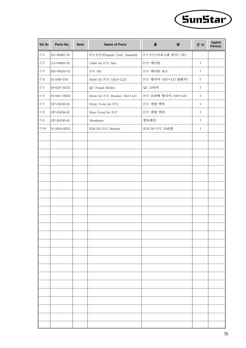
75
C-1
C-2
C-3
C-4
C-5
C-6
C-7
C-8
C-9
C-10
Q’ tyRef. No. Parts No. Note Name of Parts 품품 명명 AppliedPeriod.
EA-000467-00
CA-004891-00
BD-000255-02
01-036S-1701
09-023C-SC53
91-001C-SE50
GP-024743-00
GP-024744-00
GP-024745-00
91-200A-SE55
F-6 P/U(Program Unit) Assembly
Cable for P/U Box
P/U BD
Screw for P/U (M3*L12)
QC Passed Sticker
Screw for P/U Bracket (M4*L6)
Front Cover for P/U
Rear Cover for P/U
Membrane
KM-250 P/U Bracket
F-6 P/U(프로그램 유닛) (조)
P/U 케이블
P/U 케이블 보드
P/U 죔나사 (M3*L12 플랜지)
QC 스티커
P/U 브라켓 죔나사 (M4*L6)
P/U 전면 커버
P/U 후면 커버
멤브레인
KM-250 P/U 브라켓
1
1
5
1
3
1
1
1
1

76
DD PPeeddaall MMeecchhaanniissmm
8
10
12
19
2122
20
182
28
18
23
25
26
24
31
3
3-1
3-3
3-2
4
5
9
11
3027
7
6
17
16
15
14
13
29
1

77
D-1
D-2
D-3
D-3-1
D-3-2
D-3-3
D-4
D-5
D-6
D-7
D-8
D-9
D-10
D-11
D-12
D-13
D-14
D-15
D-16
D-17
D-18
D-19
D-20
D-21
D-22
D-23
D-24
D-25
D-26
D-27
D-28
D-29
D-30
D-31
Q’ tyRef. No. Parts No. Note Name of Parts 품품 명명 AppliedPeriod.
EA-000460-00
GP-014593-01
EE-002736-00
CA-004873-00
BD-000252-01
10-014B-SC53
10-028S-SC53
06-001C-SE55
10-016A-SC53
10-024P-SC53
10-025P-SC53
10-019G-SC53
10-020G-SC53
10-029P-SC53
10-030P-SC53
10-021S-SC53
10-031W-SC53
10-031S-SC53
11-012C-3701
10-017A-SC53
10-025A-SC53
03-004S-SM5S
10-024P-3701
10-024W-SC53
10-026A-SC53
10-027C-SC53
03-004S-SM5S
10-018G-SC53
10-033C-SF55
91-007A-3701
07-027S-SE55
09-023C-SC53
1
1
1Set
1
1
1
3
1
1
1
1
1
1
1
1
2
2
2
2
2
2
1
1
1
1
1
1
1
2
1
2
1
4
1
F-6 Pedal Unit Assembly
Pedal Base
Pedal BD Assembly
Cable for Pedal Unit
Pedal Board
Hall Sensor Housing
Screw for Pedal Unit (M3×L7)
Rubber Cap for Up Pedal Base
Spring Housing
Spring Guide (A)
Spring Guide (B)
Pressure Spring for Pressure Foot
Pressure Spring for Thread Trimming
Stopper for Pressure Spring (A)
Stopper for Pressure Spring (B)
Pressure Control Screw (M4×L10)
Pressure Control Nut (M4)
Spring Washer for Pressure Control (Ø4)
Washer for Pressure Control (Ø4)
Screw for Spring Housing (M4×L6)
Bushing for Pedal Control Lever
Pedal Control Lever
Shaft for Pedal Control Lever
Screw for Pedal Control Lever (M5×L6)
Fixing Pin for Pedal Control Lever(Ø4×L10)
Flat Washer for Pedal Shaft (Ø8)
Base for Pedal Magnet & Film
Pedal Magnet
Base Screw for Pedal Magnet&Film (M5×L6)
Tension Spring for Pedal
Rubber Cap for Pedal Base
Pedal Control Rod Assembly
Pedal Screw(M5×L10)
QC Passed Sticker
F-6 패달 유닛 (조)
페달 베이스
패달 보드 (조)
페달 입력 케이블
페달 보드
홀센서 하우징
페달 보드 죔나사 (조) (M3×L7)
페달 베이스 위쪽 마개
스프링 하우징
스프링 가이드 A
스프링 가이드 B
노루발 압력 스프링
사절 압력 스프링
압력 스프링 스토퍼 A
압력 스프링 스토퍼 B
압력 조절 나사 (M4×L10)
압력 조절 너트(M4)
압력 조절 스프링 와셔 (Ø4)
압력 조절 평 와셔 (Ø4)
스프링 하우징 죔나사 (M4×L6)
페달 콘트롤 레버 부싱
페달 콘트롤 레버
페달 콘트롤 레버 축
페달 콘트롤 레버 죔나사 (M5×L6)
페달 콘트롤 레버 고정 핀 (Ø4×L10)
페달 축 평와셔 (Ø8)
페달 마그네트 & 필름 베이스
페달 마그네트
페달 마그네트&필름 베이스 죔나사 (M5×L6)
페달 인장 스프링
페달 베이스 고무마게
페달 연결 롯드 (조)
페달 죔나사 (조) (M5×L10)
QC 스티커