servoclass-rohs
TRANSCRIPT

Patent Pending

Zero-Max ServoClass Couplings
2
• For high performance servo motor anddemanding motion control applications
• High torsional stiffness for precision positioning
• Eco-Friendly, Adapted to RoHS Directive with no banned substances
• Low inertia for high speed applications
• Zero backlash and low hysteresis ensuresrepeatable precise positioning
• Clean Room Applications
Today’s servo motor applications are moredemanding than ever. The precision positioningrequirements and high reverse loadcharacteristics of AC and DC servomotorapplications necessitate a coupling design thatspecifically addresses the needs of thesesophisticated systems.
Inertia and torsional stiffness are criticalfeatures of a superior servo coupling. Theinertia should be low so as not to addsignificantly to overall inertia of the servosystem. The lower the inertia, the less energyrequired by the motor to move the system andtherefore, higher acceleration is possible. Thetorsional stiffness should be high enough toprevent the coupling from winding up duringacceleration, deceleration or reversingconditions. The torsional stiffness of the Zero-Max ServoClass coupling leads to
a higher system resonant frequency, which inmost cases, is far above the operating range.
Zero backlash is another key requirement of ahigh performance servo coupling. A couplingmay be considered zero backlash and stillhave a large amount of windup. Zero backlashis the ability of the coupling to maintain thesame relative relationship between the inputand output shaft without lost motion. Thewindup of the coupling can be detrimental tothe servo system. A coupling with a highamount of windup will cause positioning errorsto the servo system. The Zero-Max ServoClasscoupling is a zero backlash coupling and itexhibits a very low amount of windup.
Misalignment capability of a coupling is alsoimportant in a motion control system. Usually,the alignment of a well manufactured servo
system will be very good. Over time and underhigh load conditions, this alignment maydeteriorate. The coupling should be capable ofhandling this change. Also, the coupling shouldaccommodate any lack of concentricity in theconnected shafts as well as the stack up oftolerances in the motion assembly. Anotherimportant benefit of a high misalignmentcapability is the dispersion of reaction loads onthe bearings and bushings in the system. TheZero-Max ServoClass coupling utilizes a designthat provides adequate amounts of flexibilitybut does not sacrifice any of the torquecapability or the torsional stiffness capabilityand therefore minimizes the reaction loads tothe servo motor bearings.
Operating Temperature Range--22° to +212°F--30° to +100°C
www.zero-max.com Phone 1-800-533-1731 763-546-4300 Fax 763-546-8260

3
ServoClass Couplings For Every Servo System Requirement
304 Stainless steel disc packs and collars
All fastenersare corrosion
resistantAluminum AlloyConstruction
Clamp HubCorrosion resistantclamp screws
www.zero-max.com Phone 1-800-533-1731 763-546-4300 Fax 763-546-8260
ServoClass couplings are available in single and double disc models. A total of 16 sizes are available.
Double disc ServoClass models provide highest misalignment capability. Single disc ServoClass modelsprovide a smaller package coupling with more torsional and axial stiffness than the Double disc model.
Torque ratings for ServoClass couplings range from 4.43 to 530 lb-in (.5 to 60 Nm). These ratings arebased on the minimum bore of the coupling. These couplings can accommodate bores sizes from 4.0mm to a maximum of 30 mm. Contact Zero-Max for larger or smaller bore sizes.
Hubs and center members of ServoClass couplings are manufactured of aluminum alloy for high strengthand durability. They are treated to prevent oxidation and to preserve appearance. Disc members aremade of 304 stainless steel providing torsional stiffness and some misalignment capability.
Coupling assembly/hub design. ServoClass couplings are precisely assembled using highest strength,corrosion resistant fasteners. The couplings also have integral clamp style hubs for fast and easymounting. The design allows for specifying combinations of inch and mm hub bore sizes and styles.
RoHS Compliant. ServoClass couplings are manufactured of RoHS compliant materials and contain nobanned substances.

The shafts of the equipment (up to the maximum bore size of the coupling) may be extended into the interior of the coupling without any modification to the
ServoClass coupling. However, the ends of the shafts must never touch each other.
LBC
L
A1øDøD2øD1
M
øN
S
LBC
L
A1øDøD2øD1
M
øN
A2
S
LBC
L
A2
øDøD2øD1
M
S
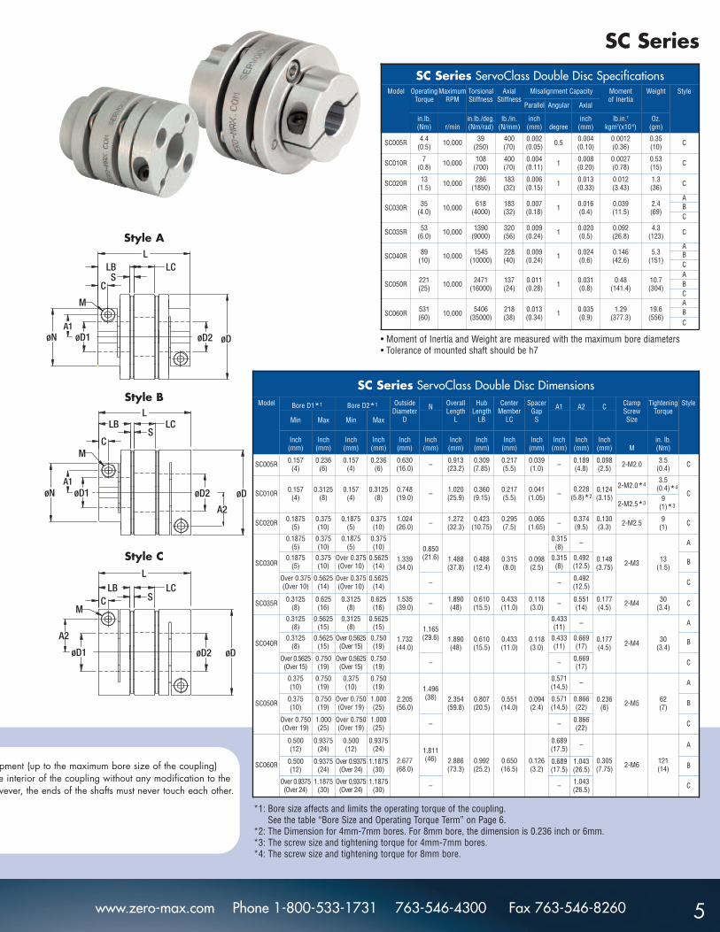
Style A
Style B
Style C
SD Series
4
SD Series ServoClass Single Disc SpecificationsModel Operating
TorqueMaximum
RPMTorsionalStiffness
AxialStiffness
Misalignment Capacity Moment of Inertia
Weight Style
Parallel Angular Axial
in.lb.(Nm) r/min
in.lb./deg.(Nm/rad)
lb./in.(N/mm)
inch(mm) degree
inch(mm)
lb.in.2
kgm2(x10-6)Oz.
(gm)
SD005R 4.4(0.5) 10,000 77
(500)799
(140)0.001(0.02) 0.5 0.002
(0.05)0.0009(0.26)
0.25(7) C
SD010R 7(0.8) 10,000 216
(1400)799
(140)0.001(0.02) 1 0.004
(0.10)0.0019(0.57)
0.39(11) C
SD020R 13(1.5) 10,000 572
(3700)365(64)
0.001(0.02) 1 0.006
(0.15)0.008(2.39)
0.9(25) C
SD030R 35(4.0) 10,000 1236
(8000)365(64)
0.001(0.02) 1 0.008
(0.2)0.028(8.13)
1.7(49)
ABC
SD035R 53(6.0) 10,000 2780
(18000)640
(112)0.001(0.02) 1 0.010
(0.3)0.063(18.4)
3.0(84) C
SD040R 89(10) 10,000 3089
(20000)457(80)
0.001(0.02) 1 0.012
(0.3)0.101(29.5)
3.7(105)
ABC
SD050R 221(25) 10,000 4943
(32000)274(48)
0.001(0.02) 1 0.016
(0.4)0.34
(99.3)7.5
(214)
ABC
SD060R 531(60) 10,000 10812
(70000)436
(76.4)0.001(0.02) 1 0.018
(0.5)0.92
(268.5)14.0(396)
ABC
SD Series ServoClass Single Disc DimensionsModel Bore D1*1 Bore D2*1 Outside
Diameter D
N OverallLength
L
HubLength
LB
SpacerGap S
A1 A2 C ClampScrew Size
TighteningTorque
Style
Min Max Min Max
Inch(mm)
Inch(mm)
Inch(mm)
Inch(mm)
Inch(mm)
Inch(mm)
Inch(mm)
Inch(mm)
Inch(mm)
Inch(mm)
Inch(mm)
Inch(mm) M
in. lb.(Nm)
SD005R 0.157(4)
0.236(6)
0.157(4)
0.236(6)
0.630(16.0) – 0.657
(16.7)0.309(7.85)
0.039(1.0) – 0.189
(4.8)0.098(2.5) 2-M2.0 3.5
(0.4) C
SD010R 0.157(4)
0.3125(8)
0.157(4)
0.3125(8)
0.748(19.0) – 0.762
(19.35)0.360(9.15)
0.041(1.05) –
0.228(5.8)*2
0.124(3.15)
2-M2.0*43.5
(0.4)*4C
2-M2.5*39
(1)*3
SD020R 0.1875(5)
0.375(10)
0.1875(5)
0.375(10)
1.024(26.0) – 0.911
(23.15)0.423
(10.75)0.065(1.65) – 0.374
(9.5)0.130(3.3) 2-M2.5 9
(1) C
SD030R
0.1875(5)
0.375(10)
0.1875(5)
0.375(10)
1.339(34.0)
0.850(21.6) 1.075
(27.3)0.488(12.4)
0.098(2.5)
0.315(8) –
0.148(3.75) 2-M3 13
(1.5)
A
0.1875(5)
0.375(10)
Over 0.375(Over 10)
0.5625(14)
0.315(8)
0.492(12.5) B
Over 0.375(Over 10)
0.5625(14)
Over 0.375(Over 10)
0.5625(14) – – 0.492
(12.5) C
SD035R 0.3125(8)
0.625(16)
0.3125(8)
0.625(16)
1.535(39.0) – 1.339
(34.0)0.610(15.5)
0.118(3.0) – 0.551
(14)0.177(4.5) 2-M4 30
(3.4) C
SD040R
0.3125(8)
0.5625(15)
0.3125(8)
0.5625(15)
1.732(44.0)
1.165(29.6) 1.399
(34.0)0.610(15.5)
0.118(3.0)
0.433(11) –
0.177(4.5) 2-M4 30
(3.4)
A
0.3125(8)
0.5625(15)
Over 0.5625(Over 15)
0.750(19)
0.433(11)
0.669(17) B
Over 0.5625(Over 15)
0.750(19)
Over 0.5625(Over 15)
0.750(19) – – 0.669
(17) C
SD050R
0.375(10)
0.750(19)
0.375(10)
0.750(19)
2.205(56.0)
1.496(38) 1.709
(43.4)0.807(20.5)
0.094(2.4)
0.571(14.5) –
0.236(6) 2-M5 62
(7)
A
0.375(10)
0.750(19)
Over 0.750(Over 19)
1.000(25)
0.571(14.5)
0.866(22) B
Over 0.750(Over 19)
1.000(25)
Over 0.750(Over 19)
1.000(25) – – 0.866
(22) C
SD060R
0.500(12)
0.9375(24)
0.500(12)
0.9375(24)
2.677(68.0)
1.811(46) 2.110
(53.6)0.992(25.2)
0.126(3.2)
0.689(17.5) –
0.305(7.75) 2-M6 121
(14)
A
0.500(12)
0.9375(24)
Over 0.9375(Over 24)
1.1875(30)
0.689(17.5)
1.043(26.5) B
Over 0.9375(Over 24)
1.1875(30)
Over 0.9375(Over 24)
1.1875(30) – – 1.043
(26.5) C
www.zero-max.com Phone 1-800-533-1731 763-546-4300 Fax 763-546-8260
• Moment of Inertia and Weight are measured with the maximum bore diameters• Tolerance of mounted shaft should be h7
*1: Bore size affects and limits the operating torque of the coupling.See the table “Bore Size and Operating Torque Term” on Page 6.
*2: The Dimension for 4mm-7mm bores. For 8mm bore, the dimension is 0.236 inch or 6mm.*3: The screw size and tightening torque for 4mm-7mm bores.*4: The screw size and tightening torque for 8mm bore.
LBS
LC
C
L
øDøD2øD1
M
øNA1
LBS
LC
C
L
øDøD2øD1
M
øN
A2
A1
LBS
LCC
L
øDøD2øD1
M
A2
pment (up to the maximum bore size of the coupling) he interior of the coupling without any modification to theowever, the ends of the shafts must never touch each other.
Style A
Style B
Style C
SC Series
5
SC Series ServoClass Double Disc DimensionsModel Bore D1*1 Bore D2*1 Outside
Diameter D
N OverallLength
L
HubLength
LB
CenterMember
LC
SpacerGap S
A1 A2 C ClampScrew Size
TighteningTorque
Style
Min Max Min Max
Inch(mm)
Inch(mm)
Inch(mm)
Inch(mm)
Inch(mm)
Inch(mm)
Inch(mm)
Inch(mm)
Inch(mm)
Inch(mm)
Inch(mm)
Inch(mm)
Inch(mm) M
in. lb.(Nm)
SC005R 0.157(4)
0.236(6)
0.157(4)
0.236(6)
0.630(16.0) – 0.913
(23.2)0.309(7.85)
0.217(5.5)
0.039(1.0) – 0.189
(4.8)0.098(2.5) 2-M2.0 3.5
(0.4) C
SC010R 0.157(4)
0.3125(8)
0.157(4)
0.3125(8)
0.748(19.0) – 1.020
(25.9)0.360(9.15)
0.217(5.5)
0.041(1.05) –
0.228(5.8)*2
0.124(3.15)
2-M2.0*43.5
(0.4)*4C
2-M2.5*39
(1)*3
SC020R 0.1875(5)
0.375(10)
0.1875(5)
0.375(10)
1.024(26.0) – 1.272
(32.3)0.423
(10.75)0.295(7.5)
0.065(1.65) – 0.374
(9.5)0.130(3.3) 2-M2.5 9
(1) C
SC030R
0.1875(5)
0.375(10)
0.1875(5)
0.375(10)
1.339(34.0)
0.850(21.6) 1.488
(37.8)0.488(12.4)
0.315(8.0)
0.098(2.5)
0.315(8) –
0.148(3.75) 2-M3 13
(1.5)
A
0.1875(5)
0.375(10)
Over 0.375(Over 10)
0.5625(14)
0.315(8)
0.492(12.5) B
Over 0.375(Over 10)
0.5625(14)
Over 0.375(Over 10)
0.5625(14) – – 0.492
(12.5) C
SC035R 0.3125(8)
0.625(16)
0.3125(8)
0.625(16)
1.535(39.0) – 1.890
(48)0.610(15.5)
0.433(11.0)
0.118(3.0) – 0.551
(14)0.177(4.5) 2-M4 30
(3.4) C
SC040R
0.3125(8)
0.5625(15)
0.3125(8)
0.5625(15)
1.732(44.0)
1.165(29.6) 1.890
(48)0.610(15.5)
0.433(11.0)
0.118(3.0)
0.433(11) –
0.177(4.5) 2-M4 30
(3.4)
A
0.3125(8)
0.5625(15)
Over 0.5625(Over 15)
0.750(19)
0.433(11)
0.669(17) B
Over 0.5625(Over 15)
0.750(19)
Over 0.5625(Over 15)
0.750(19) – – 0.669
(17) C
SC050R
0.375(10)
0.750(19)
0.375(10)
0.750(19)
2.205(56.0)
1.496(38) 2.354
(59.8)0.807(20.5)
0.551(14.0)
0.094(2.4)
0.571(14.5) –
0.236(6) 2-M5 62
(7)
A
0.375(10)
0.750(19)
Over 0.750(Over 19)
1.000(25)
0.571(14.5)
0.866(22) B
Over 0.750(Over 19)
1.000(25)
Over 0.750(Over 19)
1.000(25) – – 0.866
(22) C
SC060R
0.500(12)
0.9375(24)
0.500(12)
0.9375(24)
2.677(68.0)
1.811(46) 2.886
(73.3)0.992(25.2)
0.650(16.5)
0.126(3.2)
0.689(17.5) –
0.305(7.75) 2-M6 121
(14)
A
0.500(12)
0.9375(24)
Over 0.9375(Over 24)
1.1875(30)
0.689(17.5)
1.043(26.5) B
Over 0.9375(Over 24)
1.1875(30)
Over 0.9375(Over 24)
1.1875(30) – – 1.043
(26.5) C
SC Series ServoClass Double Disc SpecificationsModel Operating
TorqueMaximum
RPMTorsionalStiffness
AxialStiffness
Misalignment Capacity Moment of Inertia
Weight Style
Parallel Angular Axial
in.lb.(Nm) r/min
in.lb./deg.(Nm/rad)
lb./in.(N/mm)
inch(mm) degree
inch(mm)
lb.in.2
kgm2(x10-6)Oz.
(gm)
SC005R 4.4(0.5) 10,000 39
(250)400(70)
0.002(0.05) 0.5 0.004
(0.10)0.0012(0.36)
0.35(10) C
SC010R 7(0.8) 10,000 108
(700)400(70)
0.004(0.11) 1 0.008
(0.20)0.0027(0.78)
0.53(15) C
SC020R 13(1.5) 10,000 286
(1850)183(32)
0.006(0.15) 1 0.013
(0.33)0.012(3.43)
1.3(36) C
SC030R 35(4.0) 10,000 618
(4000)183(32)
0.007(0.18) 1 0.016
(0.4)0.039(11.5)
2.4(69)
ABC
SC035R 53(6.0) 10,000 1390
(9000)320(56)
0.009(0.24) 1 0.020
(0.5)0.092(26.8)
4.3(123) C
SC040R 89(10) 10,000 1545
(10000)228(40)
0.009(0.24) 1 0.024
(0.6)0.146(42.6)
5.3(151)
ABC
SC050R 221(25) 10,000 2471
(16000)137(24)
0.011(0.28) 1 0.031
(0.8)0.48
(141.4)10.7(304)
ABC
SC060R 531(60) 10,000 5406
(35000)218(38)
0.013(0.34) 1 0.035
(0.9)1.29
(377.3)19.6(556)
ABC
www.zero-max.com Phone 1-800-533-1731 763-546-4300 Fax 763-546-8260
• Moment of Inertia and Weight are measured with the maximum bore diameters• Tolerance of mounted shaft should be h7
*1: Bore size affects and limits the operating torque of the coupling.See the table “Bore Size and Operating Torque Term” on Page 6.
*2: The Dimension for 4mm-7mm bores. For 8mm bore, the dimension is 0.236 inch or 6mm.*3: The screw size and tightening torque for 4mm-7mm bores.*4: The screw size and tightening torque for 8mm bore.
6 www.zero-max.com Phone 1-800-533-1731 763-546-4300 Fax 763-546-8260
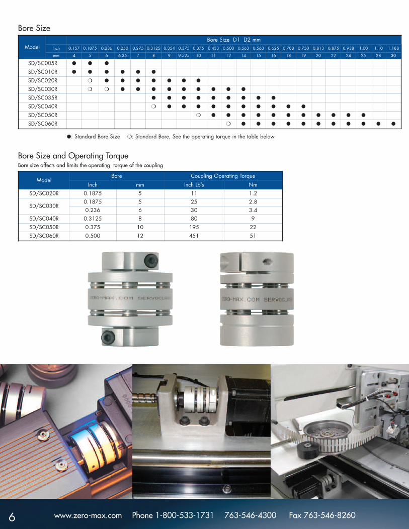
ModelBore Size D1 D2 mm
Inch 0.157 0.1875 0.236 0.250 0.275 0.3125 0.354 0.375 0.375 0.433 0.500 0.563 0.563 0.625 0.708 0.750 0.813 0.875 0.938 1.00 1.10 1.188
mm 4 5 6 6.35 7 8 9 9.525 10 11 12 14 15 16 18 19 20 22 24 25 28 30
SD/SC005R ● ● ●
SD/SC010R ● ● ● ● ● ●
SD/SC020R ❍ ● ● ● ● ● ● ●
SD/SC030R ❍ ❍ ● ● ● ● ● ● ● ● ●
SD/SC035R ● ● ● ● ● ● ● ● ●
SD/SC040R ❍ ● ● ● ● ● ● ● ● ● ●
SD/SC050R ❍ ● ● ● ● ● ● ● ● ● ● ●
SD/SC060R ❍ ● ● ● ● ● ● ● ● ● ● ●
ModelBore Coupling Operating Torque
Inch mm Inch Lb’s NmSD/SC020R 0.1875 5 11 1.2
SD/SC030R0.1875 5 25 2.80.236 6 30 3.4
SD/SC040R 0.3125 8 80 9SD/SC050R 0.375 10 195 22SD/SC060R 0.500 12 451 51
●: Standard Bore Size ❍: Standard Bore, See the operating torque in the table below
Bore Size
Bore Size and Operating TorqueBore size affects and limits the operating torque of the coupling

Additional ServoClass Coupling Applications
7
The ServoClass coupling was designed specifically for the servomotor market. Other applications include stepper motors andencoders. Typically these motors are used in applications thatinvolve positioning devices such as linear ball screws, actuators,and positioning systems (X, Y and Z-axis). The ServoClass isideal for use in machine tools, printing machines, pick andplace machines and many other high precision applications. Ifthere’s is a servomotor in the system, a ServoClass couplingshould be used!
Zero-Max provides free softwareon a CD ROM to help select andsize the correct ServoClassCoupling. This CD ROM containsall Zero-Max product catalogs ina PDF format, a comprehensivesizing and selection programand CAD drawings for most ofthe Zero-Max products.
In servomotor systems, torsionalvibration can be caused byacceleration, deceleration, drivercharacteristics and other factors.While torsional vibration isinherent in power transmissionsystems, it is important that itsfrequency and amplitude be
minimized. Torsional vibration can cause component failure orpoor system performance. By selecting the proper coupling thatplaces the natural frequency outside the range of 150-400 Hz,the effects of torsional vibration or resonance can be reduced.The calculated natural frequency of the system should be 1.3 to1.5 times greater than this range.
The natural torsional frequency can be calculated from a 2mass system approximation using the following equation.
F = 1/2π x √ K x (J1 + J2)J1 x J2
Where: F = Natural Frequency in HzJ1 = Inertia of the MotorJ2 = Inertia of the loadK = Torsional Stiffness of the Coupling
Other factors such as system gain, elasticity of the system anddampening can also be included in the equation. Please call usfor a natural frequency analysis of your servo system.
1. Determine the speed-revolutions per minute (RPM) and horsepower (HP). Then calculate the torque (T), in inch-pounds, to be transmitted:
T = HP x 63,025RPM
2. Select the service factor (K) according to the characteristics of the load or application. See chart below for load characteristics and service factor. Calculate the coupling selection torque (TD) based on the appropriate servicefactor:
TD = T x K3. Select a coupling with a torque rating equal or
greater than TD.
4. Check the dimensions and bore range of the coupling selected with the application requirements.
Selecting A ServoClass Coupling
Natural Frequency & Resonance
Although servomotors have different torque values relative toRPM, and torque values change relative to continuous orintermittent duty, it is suggested to use the peak torque rating ofthe servomotor multiplied by a service factor in determining thecoupling selection:
TS = TM x KS TS is the torque used to select the coupling; TM is the peaktorque of the servomotor; KS is the servo service factor of theapplication. Generally, KS is a value within the range of 1.3 to1.5 for ServoClass coupling applications. 1.3 is a factorapplied to typical reverse-load, continuous-duty applications.1.5 is a factor applied to the most demanding high reverse-load, rapid-acceleration applications. Example:
Coupling selection: SC 020, rated at 13 inch-pounds of torque..375 bore is OK.
Servomotor Peak Torque: 7.59 inch-poundsRated Torque: 2.53 inch-poundsShaft Diameter: .375 inch
TS = 7.59 x 1.5TS = 11.39 inch-pounds of torque
Load Characteristics
Constant Slight fluctuation Medium fluctuation Great fluctuation
1.0 1.25 1.75 2.25
Servomotor Application
Standard Motor Application
Sizing software for ServoClass Couplings
www.zero-max.com Phone 1-800-533-1731 763-546-4300 Fax 763-546-8260

Warranty. Zero-Max, Inc. the manufacturer, warrants that for a period of 12 months from date of shipment it will repair, or at its option, replace any new apparatus which proves defective in material or workmanship, orwhichdoes not conform to applicable drawings and specifications approved by the manufacturer. All repairs and replacements shall be F.O.B. factory. All claims must be made in writing to the manufacturer. • In no event andunder no circumstances shall manufacturer be liable for (a) damages in shipment; (b) failures or damages due to misuse, abuse, improper installation or abnormal conditions of temperature, dirt, water or corrosives; (c)failures due to operation, intentional or otherwise, above rated capacities, and (d) non-authorized expenses for removal, inspection, transportation, repair or rework. Nor shall manufacturer ever be liable for consequentialand incidental damages, or in any amount greater than the purchase price of the apparatus. • Zero Max, Inc. reserves the right to discontinue models or to change specifications at any time without notice. Nodiscontinuance or change shall create any liability on the part of Zero-Max, Inc. in respect to its products in the hands of customers or products on order not incorporating such changes even though delivered after any suchchange. • This warranty is in LIEU OF ALL OTHER WARRANTIES, EXPRESS OR IMPLIED, INCLUDING (BUT NOT LIMITED TO) ANY IMPLIED WARRANTIES OF MERCHANTABILITY OR FITNESS FOR A PARTICULAR PURPOSE. THETERMS OF THIS WARRANTY CONSTITUTE ALL BUYER’S OR USER’S SOLE AND EXCLUSIVE REMEDY, AND ARE IN LIEU OF ANY RIGHT TO RECOVER FOR NEGLIGENCE, BREACH OF WARRANTY, STRICT TORT LIABILITY OR UPON ANYOTHER THEORY. Any legal proceedings arising out of the sale or use of this apparatus must be commenced within 18 months of the date of purchase. • CAUTION: Rotating equipment must be guarded. Also refer to OSHAspecifications and recommendations. • Zero-Max®, CD®, ETP®, ServoClass®, Torq-Tender®, Control-Flex®, Posi-Lok® and Roh'Lix® are registered trademarks of Zero-Max, Inc. In U.S.A. OHLA™ is a trademark of Zero-Max,Inc. © Zero-Max 2006 Printed in U.S.A.
ServoClass® Couplingswww.zero-max.com/servo
CD® Couplingswww.zero-max.com/cd
Schmidt Offset Couplingswww.zero-max.com/offset
Torq-Tender®
www.zero-max.com/torqtender
Control-Flex® Couplingswww.zero-max.com/controlflex
ETP® Bushingswww.zero-max.com/etp
OHLA® Overhung LoadAdapterswww.zero-max.com/ohla
Zero-Max® AdjustableSpeed Driveswww.zero-max.com/drives
Crown Right AngleGear Driveswww.zero-max.com/crown
Roh’lix® Linear Actuatorswww.zero-max.com/rohlix
13200 Sixth Avenue North, Plymouth, Minnesota 55441-5509
Phone: 800-533-1731 (763) 546-4300 Fax (763) 546-8260 www.zero-max.com