session 6 dynamic modeling and systems analysis · · 2015-01-13national aeronautics and space...
TRANSCRIPT

National Aeronautics and Space Administration
www.nasa.gov
Session 6 Dynamic Modeling and Systems Analysis
4th Propulsion Control and Diagnostics Workshop Ohio Aerospace Institute (OAI)
Cleveland, OH December 11-12, 2013
1
1:00 – 1:05p Overview – Jeffrey Csank
1:05 – 1:30p Dynamic Systems Analysis – Jeffrey Csank
1:30 – 1:55p T-MATS (Toolbox for the Modeling and Analysis of Thermodynamic Systems) – Jeffryes Chapman
1:55 – 2:20p Reducing Conservatism in Aircraft Engine Response Using Conditionally Active Min-Max Regulators – Ryan May
https://ntrs.nasa.gov/search.jsp?R=20140016527 2018-05-28T08:39:24+00:00Z

National Aeronautics and Space Administration
www.nasa.gov
Dynamic Systems Analysis
• Preliminary Engine Design – Systems Analysis (Steady state) – Lack of dynamic performance information
• Historical data (past experiences) • Additional conservatism in the design
• Dynamic Systems Analysis – Better predict/account for dynamic operation in PED – Allow for trade-offs between performance and operability margins
to meet future engine performance requirements – Enabled through the Tool for Turbine Engine Closed-loop Transient
Analysis (TTECTrA)
2

National Aeronautics and Space Administration
www.nasa.gov
T-MATS (Toolbox for the Modeling and Analysis of Thermodynamic Systems)
• Simulation System designed to give a user a library containing building blocks that may be used to create dynamic Thermodynamic systems. Includes:
- Iterative Solving capability - Generic Thermodynamic Component models
Turbomachinery components (compressor, turbine, burner, nozzle, etc.)
- Control system modeling (controller, actuator, sensor, etc.) • MATLAB/Simulink Based • Open Source (free of proprietary and export restrictions) • Development of T-MATS is being led by NASA Glenn Research
Center - NASA’s focus for this project is on the modeling of aerospace applications, however the T-MATS framework is extremely general and can be applied to any thermodynamic model.
3

National Aeronautics and Space Administration
www.nasa.gov
Reducing Conservatism in Aircraft Engine Response Using Conditionally Active Min-Max Limit Regulators
4
• Typical aircraft engine control is based on a Min-Max scheme
• Designed to keep the engine operating within prescribed mechanical and operational safety limits – Compares fuel flow to determine the limit that is closest to being
violated – Conservative
• Improve engine performance by allowing the limit regulators to only be active when a limit is in danger of being violated.
National Aeronautics and Space Administration
www.nasa.gov
Dynamic Systems Analysis
4th Propulsion Control and Diagnostics Workshop Ohio Aerospace Institute (OAI)
Cleveland, OH December 11-12, 2013
5
Jeffrey Csank NASA Glenn Research Center

National Aeronautics and Space Administration
www.nasa.gov
Team Members
• Jonathan Seidel, NASA Glenn Research Center/RTM • Jeffrey Chin, NASA Glenn Research Center/RTM • Alicia Zinnecker, N&R Engineering • Georgia Institute of Technology
6

National Aeronautics and Space Administration
www.nasa.gov
Outline
• Preliminary Engine Design • Systems Analysis • Tool for Turbine Engine Closed-loop Transient
Analysis (TTECTrA) • Dynamic Systems Analysis • Conclusion
7
National Aeronautics and Space Administration
www.nasa.gov
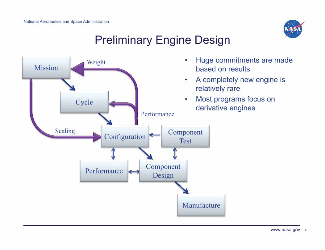
Preliminary Engine Design • Huge commitments are made
based on results • A completely new engine is
relatively rare • Most programs focus on
derivative engines
8
Weight
Performance
Scaling
Mission
Cycle
Configuration
Component Design
Component Test
Performance
Manufacture
National Aeronautics and Space Administration
www.nasa.gov
Systems Analysis
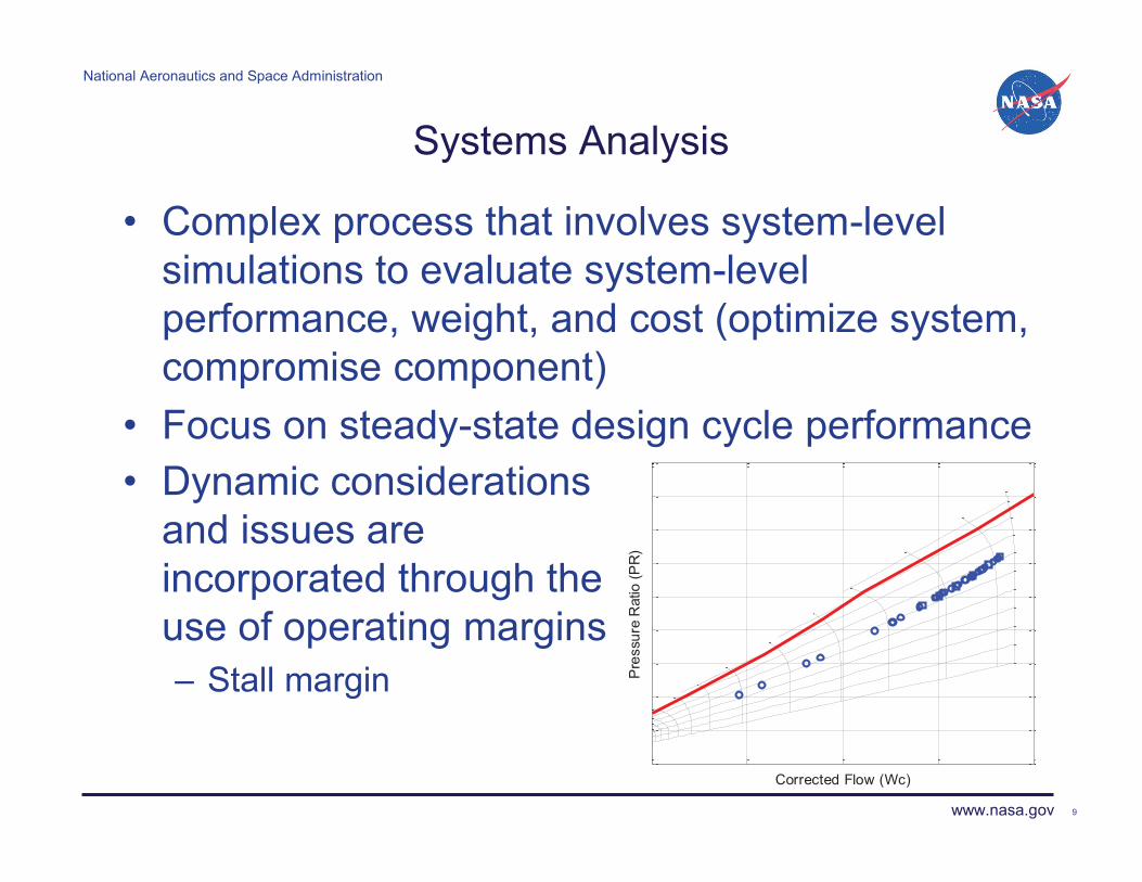
• Complex process that involves system-level simulations to evaluate system-level performance, weight, and cost (optimize system, compromise component)
• Focus on steady-state design cycle performance • Dynamic considerations
and issues are incorporated through the use of operating margins – Stall margin
9
Corrected Flow (Wc)
Pre
ssur
e R
atio
(PR
)

National Aeronautics and Space Administration
www.nasa.gov
Tool for Turbine Engine Closed-loop Transient Analysis (TTECTrA)
• Capable of automatically designing a controller • Easily integrates with users engine model in
MATLAB/Simulink environment • Provide an estimate of the closed-loop transient
performance/capability of a conceptual engine design • Requirements:
– MATLAB®/Simulink® (Release R2012b or later) • MATLAB® Version 8.0 (R2012b) • Simulink® Version 8.0 (R2012b) • Control Systems Toolbox® Version 9.4 (R2012b)
– Engine Model compatible with Simulink – State space linear model in MATLAB
10

National Aeronautics and Space Administration
www.nasa.gov
TTECTrA Architecture
• TTECTrA software automatically designs: – Set Point – Set Point Controller – Limit Controller
• Simulates different thrust profiles
11
User Model Set Point Controller
Limit Controller
Engine
Sensors
Selector Logic
Desired Thrust
Set Point
Actuator
Feedback
Error Fuel Flow Engine
Outputs Set Point
National Aeronautics and Space Administration
www.nasa.gov
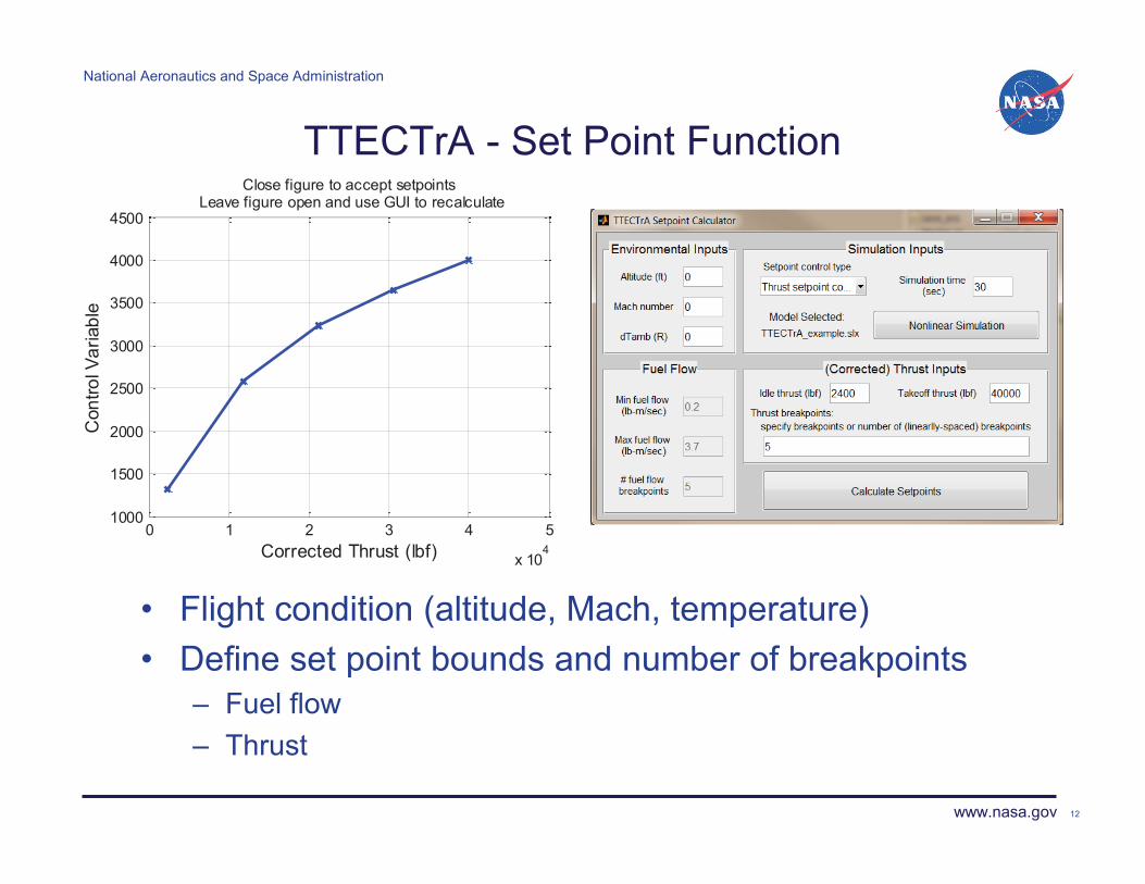
TTECTrA - Set Point Function
• Flight condition (altitude, Mach, temperature) • Define set point bounds and number of breakpoints
– Fuel flow – Thrust
12
0 1 2 3 4 5
x 104
1000
1500
2000
2500
3000
3500
4000
4500
Close figure to accept setpointsLeave figure open and use GUI to recalculate
Corrected Thrust (lbf)
Con
trol V
aria
ble
National Aeronautics and Space Administration
www.nasa.gov
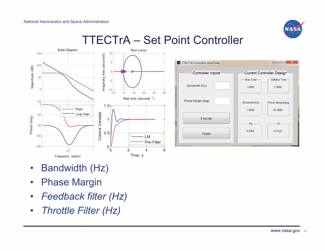
TTECTrA – Set Point Controller
• Bandwidth (Hz) • Phase Margin • Feedback filter (Hz) • Throttle Filter (Hz)
13
-50
0
50
100
150
Mag
nitu
de (
dB)
100
-180
-135
-90
-45
0
Pha
se (d
eg)
Bode Diagram
Frequency (rad/s)
PlantLoop Gain
-10 0 10 20 30 40-10
-5
0
5
10Root Locus
Real Axis (seconds -1)Im
agin
ary
Axi
s (s
econ
ds-1
)
0 2 4 60
0.5
1
1.5
Time, s
Con
trol
Var
iabl
e
LMPre-Filter
National Aeronautics and Space Administration
www.nasa.gov
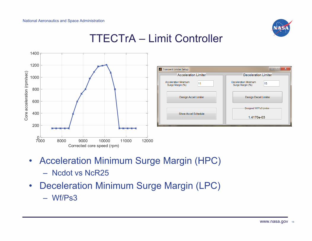
TTECTrA – Limit Controller
• Acceleration Minimum Surge Margin (HPC) – Ncdot vs NcR25
• Deceleration Minimum Surge Margin (LPC) – Wf/Ps3
14
7000 8000 9000 10000 11000 120000
200
400
600
800
1000
1200
1400
Corrected core speed (rpm)
Cor
e ac
cele
ratio
n (r
pm/s
ec)

National Aeronautics and Space Administration
www.nasa.gov
User Model
TTECTrA - Selector Logic / Actuator
• Selector Logic (Min/Max scheme) – Min (Set Point, Acceleration) – Max (Min, Deceleration)
• Actuators – Currently only models fuel flow – First order filter
15
Engine
Sensors
Selector Logic
Desired Thrust
Set Point
Actuator
Feedback
Error Fuel Flow Engine
Outputs
Set Point Set Point Controller
Limit Controller
Actuator
National Aeronautics and Space Administration
www.nasa.gov
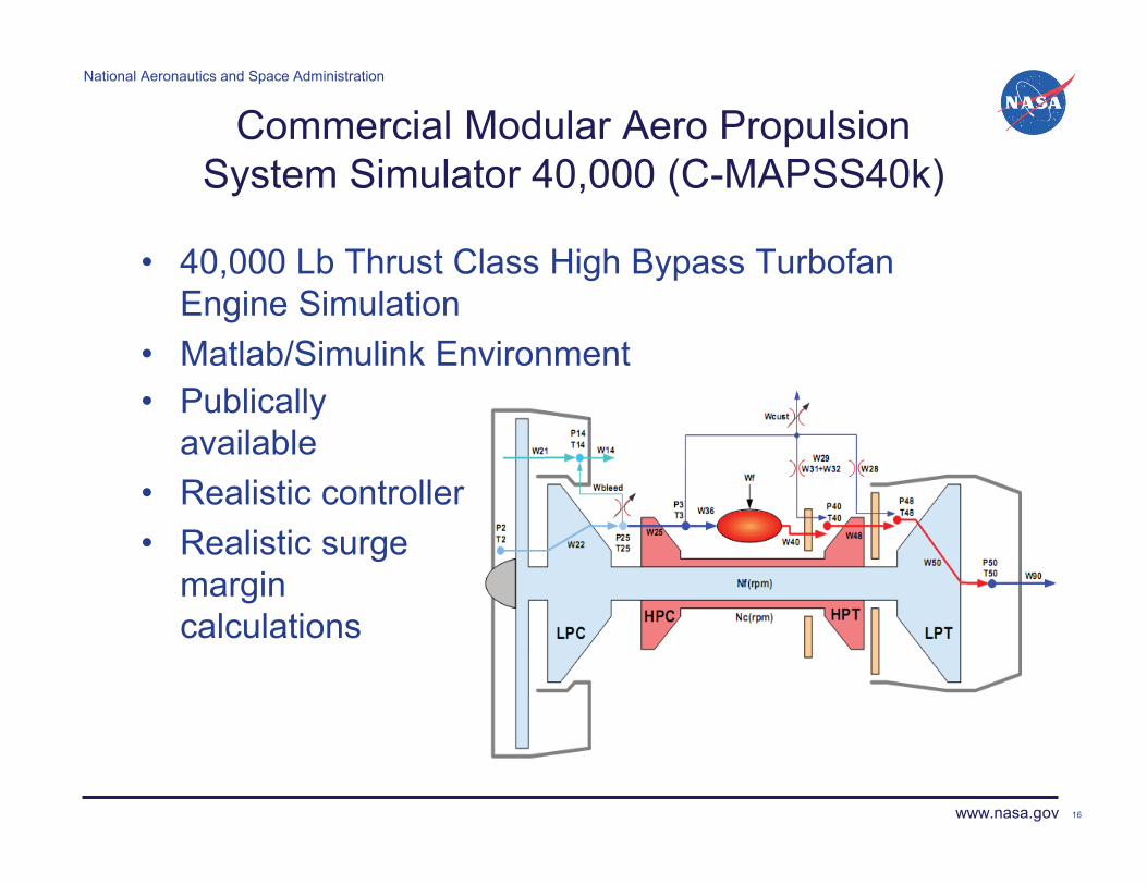
Commercial Modular Aero Propulsion System Simulator 40,000 (C-MAPSS40k)
• 40,000 Lb Thrust Class High Bypass Turbofan Engine Simulation
• Matlab/Simulink Environment
16
• Publically available
• Realistic controller • Realistic surge
margin calculations
National Aeronautics and Space Administration
www.nasa.gov
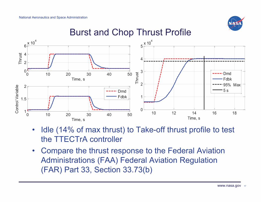
Burst and Chop Thrust Profile
• Idle (14% of max thrust) to Take-off thrust profile to test the TTECTrA controller
• Compare the thrust response to the Federal Aviation Administrations (FAA) Federal Aviation Regulation (FAR) Part 33, Section 33.73(b)
17
0 10 20 30 40 500
2
4
6x 10
4
Time, s
Thru
st
0 10 20 30 40 501
1.5
2
Time, s
Con
trol V
aria
ble
DmdFdbk
10 12 14 16 180
1
2
3
4
5x 10
4
Time, s
Thr
ust
DmdFdbk95% Max5 s

National Aeronautics and Space Administration
www.nasa.gov
Burst and Chop Thrust Profile
18
0 10 20 30 40 5010
20
30
40
50
HPC
SM
, %
Time, s
6000 8000 10000 12000-1000
-500
0
500
1000
1500
2000
Nc do
t
NcR25
0 10 20 30 40 5010
20
30
40
50
60
LPC
SM
, %
Time, s
0 10 20 30 40 500
0.002
0.004
0.006
0.008
0.01
0.012
Wf/P
s3
Time, s

National Aeronautics and Space Administration
www.nasa.gov
Engine Deterioration
19
0 20 40 6010
20
30
40
50
Time, s
HPC
SM
, %
0 20 40 6010
20
30
40
50
60
Time, s
LPC
SM
0 20 40 601
1.2
1.4
1.6
1.8
Time, s
Con
trol V
aria
ble
0 20 40 600
1
2
3
4
5x 10
4
Time, s
Thru
st, l
bf
NewEOL
National Aeronautics and Space Administration
www.nasa.gov
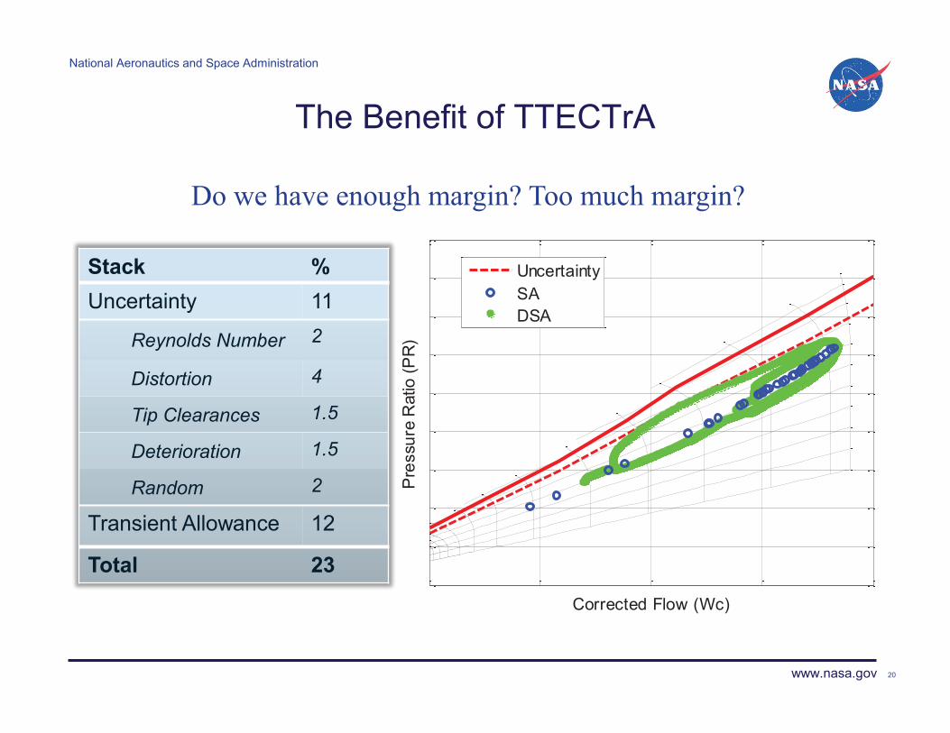
The Benefit of TTECTrA
Stack % Uncertainty 11
Reynolds Number 2
Distortion 4
Tip Clearances 1.5
Deterioration 1.5
Random 2
Transient Allowance 12
Total 23
20
Do we have enough margin? Too much margin?
Corrected Flow (Wc)
Pre
ssur
e R
atio
(PR
)
UncertaintySADSA
National Aeronautics and Space Administration
www.nasa.gov
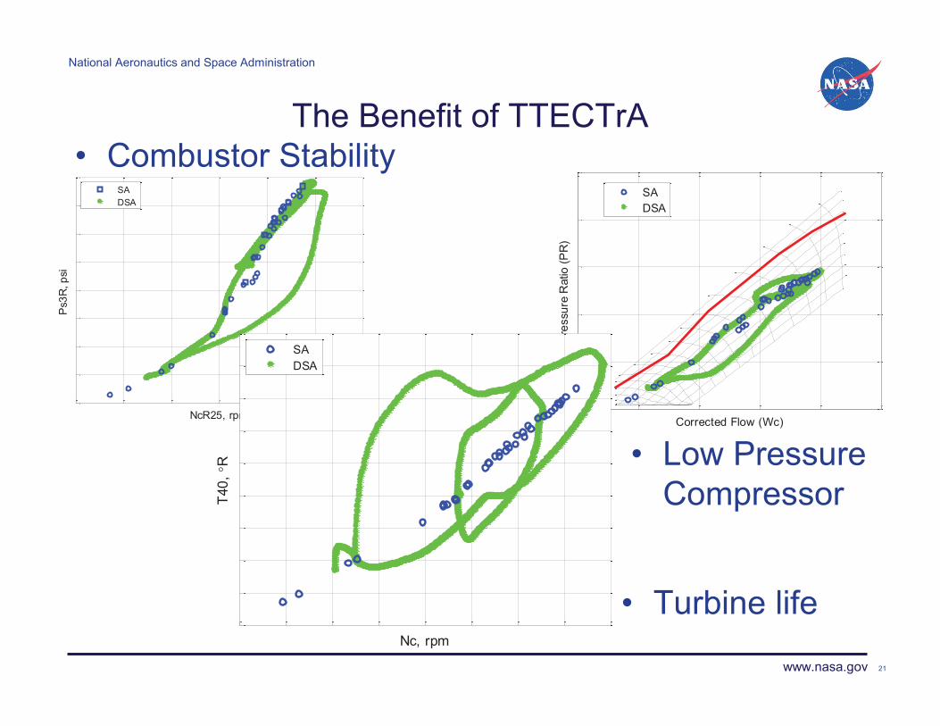
The Benefit of TTECTrA • Combustor Stability
21
• Turbine life
• Low Pressure Compressor
NcR25, rpm
Ps3
R, p
si
SADSA
Corrected Flow (Wc)
Pre
ssur
e R
atio
(PR
)
SADSA
Nc, rpm
T40,
�R
SADSA
National Aeronautics and Space Administration
www.nasa.gov
Future Work
• NPSS Model in Simulink – Georgia Institute of Technology
• Integrate TTECTrA with the NPSS Simulink model – NASA/RHC
• Integrate TTECTrA/NPSS Simulink with a larger
systems analysis optimization algorithm – NASA/RHC and NASA/RTM
22

National Aeronautics and Space Administration
www.nasa.gov
Conclusion
• Dynamic systems analysis: – Enables engine transient performance to be accounted for in
the optimization of the engine design and early in the preliminary design of turbine engines.
– Allows trading of overly conservative surge margin for better performance through system redesign (or opline).
• Developed the Tool for Turbine Engine Closed-loop
Transient Analysis (TTECTrA) – Capable of automatically designing a controller at a single
flight condition. – Easily integrates with users engine model in
MATLAB/Simulink environment. – Open source
23

National Aeronautics and Space Administration
www.nasa.gov
Questions?
24
Thank you

National Aeronautics and Space Administration
www.nasa.gov
Toolbox for the Modeling and Analysis of Thermodynamic Systems
(T-MATS)
Jeffryes W. Chapman Vantage Partners, LLC.
25
4th Propulsion Control and Diagnostics Workshop Ohio Aerospace Institute (OAI)
Cleveland, OH December 11-12, 2013

National Aeronautics and Space Administration
www.nasa.gov 26
Team
• Jeffryes W. Chapman
Vantage Partners, LLC. Cleveland, OH 44135
• Thomas M. Lavelle
NASA Glenn Research Center, Cleveland, OH 44135
• Ryan D. May
Vantage Partners, LLC. Cleveland, OH 44135
• Jonathan S. Litt
NASA Glenn Research Center, Cleveland, OH 44135
• Ten-Huei Guo
NASA Glenn Research Center, Cleveland, OH 44135

National Aeronautics and Space Administration
www.nasa.gov 27
Outline
• T-MATS Description
• Background
• Framework
• Block Sets
• Examples
• Conclusion
• Future work

National Aeronautics and Space Administration
www.nasa.gov
T-MATS Description
• Toolbox for the Modeling and Analysis of Thermodynamic systems, T-MATS – Modular thermodynamic modeling framework – Designed for easy creation of custom Component Level Models
(CLM) – Built in MATLAB®/Simulink®
• Package highlights – General thermodynamic simulation design framework – Variable input system solvers – Advanced turbo-machinery block sets – Control system block sets
• Development being led by NASA Glenn Research Center – Non-proprietary, free of export restrictions, and open source
• Open collaboration environment

National Aeronautics and Space Administration
www.nasa.gov
Background
• Thermodynamic simulation examples Model Type Examples
Steady-State (system convergence may be required)
Gas turbine cycle model • e.g., performance models
Dynamic with Quasi-steady-state variables (multi-iteration simulation; time and system convergence)
Gas turbine model with spool dynamics only. (real time running capability) • e.g., control models
Fully Defined Dynamic Simulation (iteration over time)
Dynamic gas turbine model with spool and volume dynamics (typically runs more slowly) • e.g., near stall performance models

National Aeronautics and Space Administration
www.nasa.gov
Background: Industry Study
Package User Friendly*
Flexibility* Export Restricted
Source code available
Dynamic Control System
Cost
C-MAPSS40k, NASA
High Low Yes Yes
Yes Yes MATLAB
Matlab: Thermlib toolbox, Eutech
High Medium No No Yes
No MATLAB + $4900
Cantera, Open source
Low High No Yes No No None
Gas Turbine Simulation Program (GSP), NRL
Medium Medium No No Yes Yes $4,000
GasTurb, Nrec Medium Low No No Yes Yes $1340
T-MATS, NASA High High No Yes Yes Yes MATLAB
Definitions: 1* User Friendly, Controls Perspective Low : Code based Med: Model based High: Model based with package implemented in a platform that is an industry standard
2* Flexibility Low : Plant configuration set Med: Object oriented, objects difficult to update High: Object oriented, objects easily adaptable by user

National Aeronautics and Space Administration
www.nasa.gov 31
T-MATS Framework
• T-MATS is a plug-in for a MATLAB/Simulink platform – additional blocks in the Simulink Library Browser:
– additional diagram tools for model development in Simulink:
Faster and easier model creation
Added Simulink Thermodynamic modeling and numerical solving functionality

National Aeronautics and Space Administration
www.nasa.gov 32
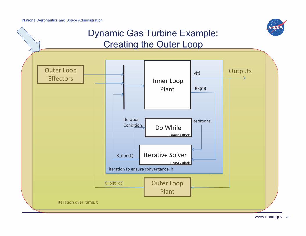
T-MATS Framework • Dynamic Simulation Example:
– Multi-loop structure • The “outer” loop (green) iterates in the time domain
– Not required for steady-state models
• The “inner” loop (blue) solves for plant convergence during each time step

National Aeronautics and Space Administration
www.nasa.gov
Blocks: Numerical Solver • Many Thermodynamic models are partially defined and require a solver to
ensure model conservation (e.g., mass, energy, etc.). – In many gas turbine simulations, component flow will typically be solved by an
independent solver.
• T-MATS contains solvers that perform in two main steps: – Automated Jacobian (system gradient) Calculation
• Each plant input is perturbed to find the effect on each plant output. – Newton-Raphson method is used to “converge” the system.
where,
33
National Aeronautics and Space Administration
www.nasa.gov
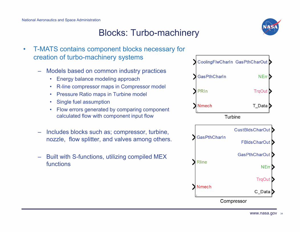
Blocks: Turbo-machinery
– Models based on common industry practices • Energy balance modeling approach • R-line compressor maps in Compressor model • Pressure Ratio maps in Turbine model • Single fuel assumption • Flow errors generated by comparing component
calculated flow with component input flow
– Includes blocks such as; compressor, turbine, nozzle, flow splitter, and valves among others.
– Built with S-functions, utilizing compiled MEX functions
34
• T-MATS contains component blocks necessary for creation of turbo-machinery systems
National Aeronautics and Space Administration
www.nasa.gov
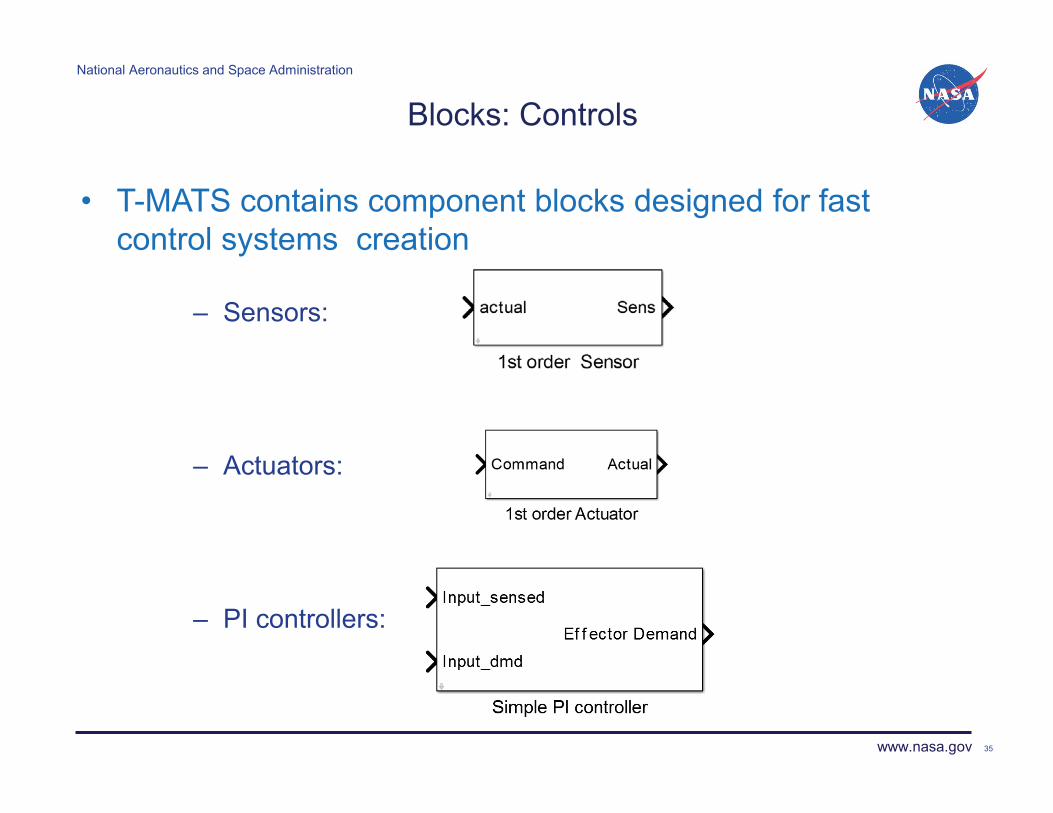
Blocks: Controls
– Sensors:
– Actuators:
– PI controllers:
35
• T-MATS contains component blocks designed for fast control systems creation

National Aeronautics and Space Administration
www.nasa.gov
Blocks: Settings
36
• The T-MATS Simulation System is a highly tunable and flexible framework for Thermodynamic modeling.
– T-MATS block Function Block Parameters • fast table and variable updates
– Open source code
• flexibility in component composition, as equations can be updated to meet system design
– MATLAB/Simulink development
environment • user-friendly, powerful, and versatile
operation platform for model design
National Aeronautics and Space Administration
www.nasa.gov
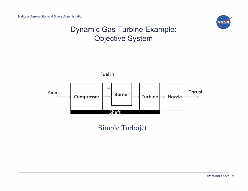
Dynamic Gas Turbine Example: Objective System
37
Simple Turbojet

National Aeronautics and Space Administration
www.nasa.gov 38
Dynamic Gas Turbine Example: Creating the Inner Loop

National Aeronautics and Space Administration
www.nasa.gov
Dynamic Gas Turbine Example: Inner Loop Plant
39
Turbojet plant model architecture made simple by T-MATS vectored I/O and block labeling
Input
Compressor
Burner
Turbine Nozzle
Shaft

National Aeronautics and Space Administration
www.nasa.gov 40
Dynamic Gas Turbine Example: Creating the Solver

National Aeronautics and Space Administration
www.nasa.gov
Dynamic Gas Turbine Example: Solver
41
Plant flow errors driven to zero by iterative solver block in parallel with While Iterator
Simulink While Iterator block
Iterative Solver
Inner Loop Plant from previous slide
National Aeronautics and Space Administration
www.nasa.gov
Outer Loop Effectors
Outer Loop Plant
X_ol(t+dt)
Outputs
Iteration over time, t
Outer Loop Effectors
Outer Loop Plant
X_ol(t+dt)
Outputs
Iteration over time, t
42
Dynamic Gas Turbine Example: Creating the Outer Loop
Inner Loop Plant
Iterative Solver
f(x(n))
X_il(n+1)
Iteration to ensure convergence, n
y(t)
Do While Iterations
Simulink Block
Iteration Condition
T-MATS Block

National Aeronautics and Space Administration
www.nasa.gov
Dynamic Gas Turbine Example: Outer Loop Plant
43
Shaft speed integration
Environmental conditions
Simple Control System
Shaft integrator and other Outer Loop effectors added to create full system simulation
National Aeronautics and Space Administration
www.nasa.gov
Verification and Release
• Verification was performed by matching T-MATS simulation data with other established simulations. – Models chosen for verification
• NPSS steady-state turbojet model • C-MAPSS – High bypass turbofan engine model
– In all cases differences in simulation performance were within acceptable limits.
• Expected Release: Q4,2013 or Q1,2014. – Pre-built examples will include:
• Newton-Raphson equation solver • Steady state turbojet simulation • Dynamic turbojet simulation
44

National Aeronautics and Space Administration
www.nasa.gov
Conclusions
• T-MATS offers a comprehensive thermodynamic simulation system – Thermodynamic system modeling framework – Automated system “convergence” – Advanced turbo-machinery modeling capability – Fast controller creation block set
45

National Aeronautics and Space Administration
www.nasa.gov
Future Work
• Increase thermodynamic modeling capability – Introduce Cantera to T-MATS
• “Cantera is a suite of object-oriented software tools for problems involving chemical kinetics, thermodynamics, and/or transport processes”
• Open source • Increases thermodynamic modeling capability to include:
– Non-fuel specific gas turbine modeling – Fuel cells – Combustion – Chemical Equilibriums
46
O + CH �H + CO

National Aeronautics and Space Administration
www.nasa.gov
Reducing Conservatism in Aircraft Engine Response Using Conditionally Active Min-Max
Limit Regulators
Ryan D. May Vantage Partners, LLC
Sanjay Garg NASA Glenn Research Center
4th Propulsion Control and Diagnostics Workshop
Ohio Aerospace Institute (OAI) Cleveland , OH
December 11-12th, 2013
National Aeronautics and Space Administration
www.nasa.gov

National Aeronautics and Space Administration
www.nasa.gov
Overview
• Introduction • Baseline Control Architecture • Conditionally Active Limit Regulator Approach • Simulation Examples • Conclusions & Future Work
NASA GRC Propulsion Control and Diagnostics Workshop 48

National Aeronautics and Space Administration
www.nasa.gov
Introduction
• The primary task of an engine control system is to deliver the guaranteed performance while ensuring safe operation throughout operating envelope over the life of the engine
• Guaranteed performance is defined as meeting the FAA certification requirements for engine responsiveness – maximum allowed 95% rise time for idle to max thrust command
NASA GRC Propulsion Control and Diagnostics Workshop 49

National Aeronautics and Space Administration
www.nasa.gov
Baseline Control Architecture
• Typical aircraft engine control is based on a Min-Max scheme
• Designed to keep the engine operating within prescribed mechanical and operational safety limits
NASA GRC Propulsion Control and Diagnostics Workshop 50
n

National Aeronautics and Space Administration
www.nasa.gov
Engine Response with Baseline Control • C-MAPSS40k Full throttle burst at sea-level static
conditions with an end-of-life engine
NASA GRC Propulsion Control and Diagnostics Workshop 51
14 15 16 17 18 19 20
1.1
1.2
1.3
1.4
1.5
EP
R
14 15 16 17 18 19 200
1
2
3
4x 10
4
time [s]
F net [l
bf]
EPR SetpointBaseline
14 15 16 17 18 19 20
0
1
time [s]
Acc
el L
imit
Act
ive
0.9 0.95 1 1.05 1.1 1.15 1.2
x 104
0
500
1000
1500
dNc/
dt [r
pm/s
]
Nc [rpm]
14 15 16 17 18 19 200
10
20
30
40
HP
C S
urge
Mar
gin
time [s]
BaselineLimit
• Acceleration limit regulator is active immediately even though it is far from the limit - Conservative Response

National Aeronautics and Space Administration
www.nasa.gov
Is the Conservative Response an issue? • No:
• Not during normal flight as long as it meets the FAA response requirements
• Yes: • On aircraft where primary flight control surfaces are damaged
(e.g. UAL 232, Bagdad DHL, AA 587) • On aircraft with integrated flight/propulsion control
• Can we improve the engine response while maintaining the current architecture?
NASA GRC Propulsion Control and Diagnostics Workshop 52

National Aeronautics and Space Administration
www.nasa.gov
The Case for Conditionally Active Limit Regulators
• The baseline Min-Max selection control approach is inherently conservative
• Every limit regulator is capable of limiting fuel flow to engine – regardless of proximity to current limit
• Depending on how the individual PI regulators are tuned, the regulator may intervene when there is no danger of a limit being violated
• To reduce conservatism, limit regulators should become active only when a limit is in “danger” of being violated.
NASA GRC Propulsion Control and Diagnostics Workshop 53

National Aeronautics and Space Administration
www.nasa.gov
Conditionally Active Limit Regulators
• For operation with reduced conservatism while still ensuring safety, following two criteria must both be satisfied to enable a limit regulator: 1) The regulated variable must be “close” to the specified limit 2) The rate of change of the regulated variable is such that the
regulated variable will reach the limit within a specified number of control update time steps
NASA GRC Propulsion Control and Diagnostics Workshop 54

National Aeronautics and Space Administration
www.nasa.gov
Conditionally Active Limit Regulators
• The conditions for the limit regulator to be active can be stated as:
For a maximum limit variable y1 with limit y1max:
–where α1 and β1 are positive design parameters
• Similar equations can be developed for minimum limit variables
NASA GRC Propulsion Control and Diagnostics Workshop 55
max111 )1( yy ����
max1111 yTydtdy �����

National Aeronautics and Space Administration
www.nasa.gov
Conditionally Active Limit Regulators
• Criteria 1 is satisfied at tA
• Criteria 2 is satisfied at tB
• Therefore the limit regulator is enabled at tB
NASA GRC Propulsion Control and Diagnostics Workshop 56
y1
t
(1-α1)y
1max
y1max
A
B
tA
tB
tA+β
1*ΔT
tB+β
1*ΔTt
A'
tB'
Graphical interpretation:
National Aeronautics and Space Administration
www.nasa.gov
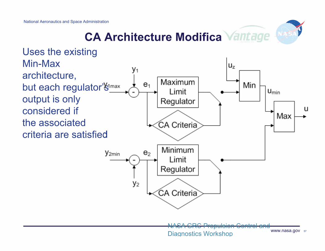
CA Architecture Modification Uses the existing Min-Max architecture, but each regulator’s output is only considered if the associated criteria are satisfied
NASA GRC Propulsion Control and Diagnostics Workshop 57
sssssssssssssssssssssssssssssssssssssssss

National Aeronautics and Space Administration
www.nasa.gov
Choice of CA Design Parameters
• We currently do not have an analytical approach to selecting the CA limit regulator design parameters α and β
• The CA parameters are tuned empirically – - � value selected first to ensure limit is not
violated for operation under worst case conditions
- With a fixed �, the β value is selected to provide fastest possible response without violating limit
• Numerical optimization algorithm has been developed
NASA GRC Propulsion Control and Diagnostics Workshop 58
National Aeronautics and Space Administration
www.nasa.gov
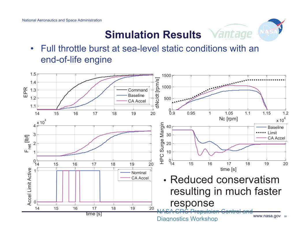
• Reduced conservatism resulting in much faster response
Simulation Results• Full throttle burst at sea-level static conditions with an
end-of-life engine
NASA GRC Propulsion Control and Diagnostics Workshop 59
14 15 16 17 18 19 20
1.1
1.2
1.3
1.4
1.5
EP
R
14 15 16 17 18 19 200
1
2
3
4x 10
4
time [s]
F net [l
bf]
CommandBaselineCA Accel
14 15 16 17 18 19 200
1
time [s]
Acc
el L
imit
Act
ive
NominalCA Accel
0.9 0.95 1 1.05 1.1 1.15 1.2
x 104
0
500
1000
1500
dNc/
dt [r
pm/s
]
Nc [rpm]
14 15 16 17 18 19 200
10
20
30
40
HP
C S
urge
Mar
gin
time [s]
BaselineLimitCA Accel
National Aeronautics and Space Administration
www.nasa.gov
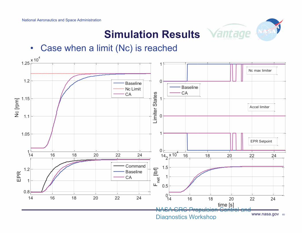
Simulation Results• Case when a limit (Nc) is reached
NASA GRC Propulsion Control and Diagnostics Workshop 60
14 16 18 20 22 241
1.05
1.1
1.15
1.2
1.25x 10
4
time [s]
Nc
[rpm
]
BaselineNc LimitCA
14 16 18 20 22 240
1
0
1
0
1
time [s]Li
mite
r Sta
tes
BaselineCA
Nc max limiter
EPR Setpoint
Accel limiter
14 16 18 20 22 240.8
1
1.2
EP
R
CommandBaselineCA
14 16 18 20 22 240
0.5
1
1.5
2x 10
4
time [s]
Fne
t [lbf
]

National Aeronautics and Space Administration
www.nasa.gov
Conclusions
• The use of properly tuned Conditionally Active limit regulators can improve the engine response without compromising safety
• This approach should simplify the tuning and validation of the limit regulator gains as the regulators are only active in a small number of possible cases
• The CA limit regulator does not require modifications to any other aspect of the well established control architecture
NASA GRC Propulsion Control and Diagnostics Workshop 61

National Aeronautics and Space Administration
www.nasa.gov
Future Work
• Formulate the CA limit regulator approach in a proper mathematical framework
• Investigate development of analytical approach to determining the CA design parameters so as to satisfy performance and safety requirements
NASA GRC Propulsion Control and Diagnostics Workshop 62
National Aeronautics and Space Administration
www.nasa.gov
References
• May, R.D., Garg, S., "Reducing Conservatism in Aircraft Engine Response Using Conditionally Active Min-Max Limit Regulators," ASME-GT2012-70017, ASME Turbo Expo 2012, Copenhagen, Denmark, June, 2012.
• Nassirharand, A., “Optimization of conditionally active MIN-MAX limit regulators for reducing conservatism in aircraft engines,” Part of 2013 NASA Glenn Faculty Fellowship Program Final Report.
NASA GRC Propulsion Control and Diagnostics Workshop 63

National Aeronautics and Space Administration
www.nasa.gov Your Title Here 64