session description and objectives · • objective…gain a fundamental understanding of: – how...
TRANSCRIPT

1
Counting Down to 2022
Vermont Society of Land SurveyorsApril 12, 2019
Dan MartinNortheast Regional Geodetic Advisor
ME, NH, VT, MA, CT, RI, NY, [email protected]
240-676-4762
• In 2022, the National Geodetic Survey will be replacing the U.S. horizontal and vertical datums (NAD 83 and NAVD 88). We will discuss the history of these datums, their relationship to other reference frames, the reasons for the change, and how it affects surveyors and their access to these datums.
• Objective…gain a fundamental understanding of:– How and why our datums/reference frames have changed over time
– The need to further modernize the US reference frames
– What Progress has been made?
– What related projects are underway?
• SPCS2022
• New horizontal and vertical transformation tool
Session description and objectives

2
National Spatial Reference System(NSRS)
NGS Mission: To define, maintain & provide access to the National Spatial Reference System (NSRS) to meet our Nation’s economic, social & environmental needs
Consistent National Coordinate System• Latitude/Northing• Longitude/Easting• Height • Scale • Gravity• Orientation & how these values change with time
GEODETIC DATUMS
HORIZONTAL2 D (Latitude and Longitude) (e.g. NAD 27, NAD 83 (1986))
VERTICAL1 D (Orthometric Height) (e.g. NGVD 29, NAVD 88, Local Tidal)
GEOMETRIC3 D (Latitude, Longitude and Ellipsoid Height)
Fixed and Stable - Coordinates seldom change (e.g. NAD 83 (1996), NAD 83 (2007), NAD 83 (CORS96) NAD 83 (2011))
also
4 D (Latitude, Longitude, Ellipsoid Height, Velocities) Coordinates change with time (e.g. ITRF00, ITRF08)

3
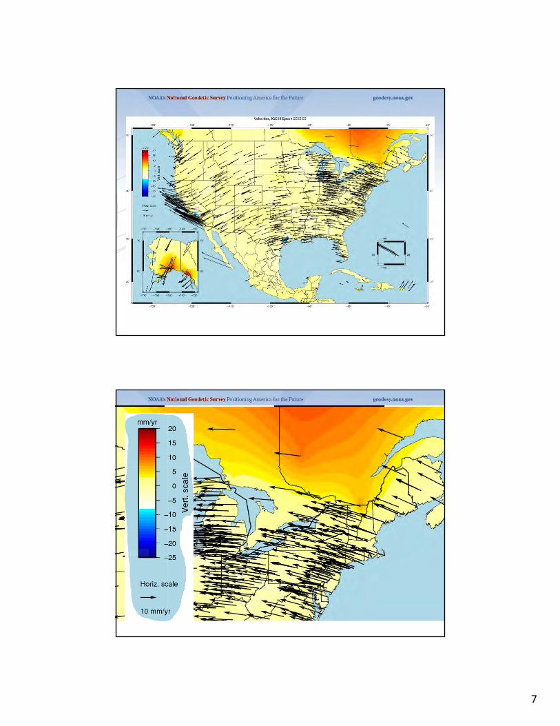
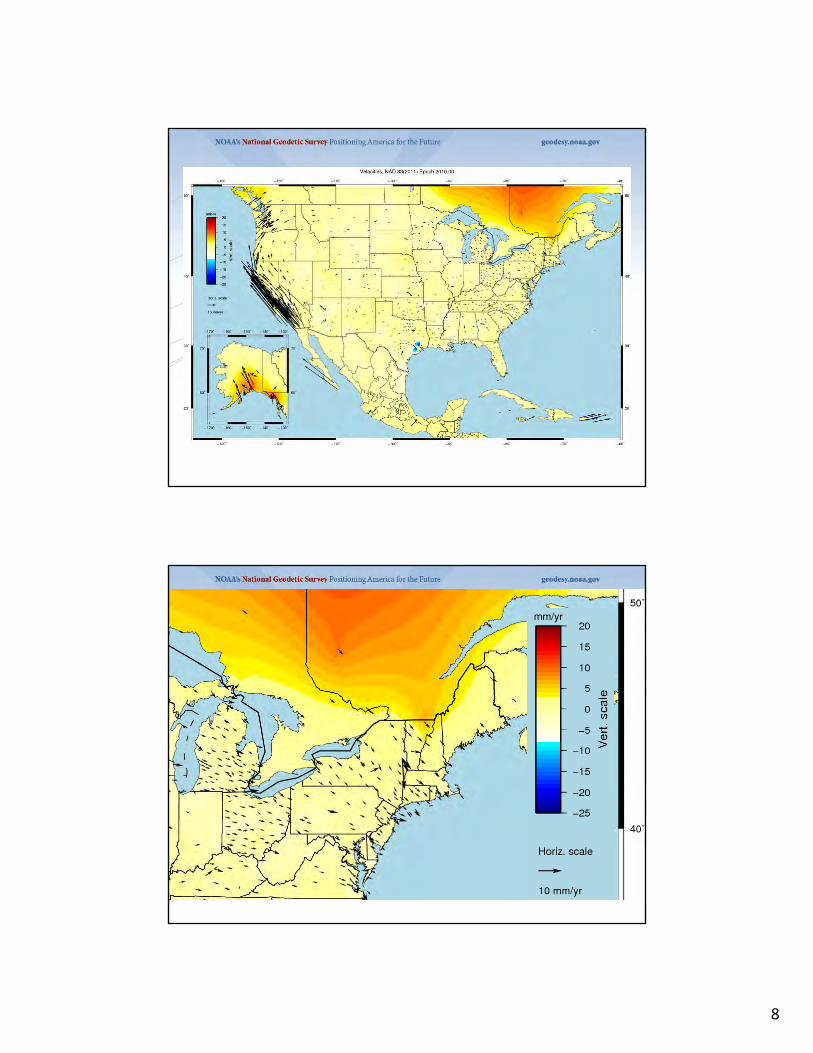
A (very) brief history of NAD 83• Original realization completed in 1986
– Consisted (almost) entirely of classical (optical) observations
• “High Precision Geodetic Network” (HPGN) and “High Accuracy Reference Network” (HARN) realizations– Most done in 1990s, essentially state-by-
state– Based on GNSS but classical stations
included in adjustments• National Re-Adjustment of 2007
– NAD 83(CORS96) and (NSRS2007)– Simultaneous nationwide adjustment
(GNSS only)• New realization: NAD 83(2011) epoch
2010.00
Why change datums/Realizations
• NAD27 based on old observations and old system
• NAD83(86) based on old observations and new system
• NAD83(96) based on new and old observations and same system (HARN)
• NAD83(NSRS2007) based on new observations and same system. Removed regional distortions and made consistent with CORS
• NAD83(2011) based on new observations and same system. Kept consistent with CORS

4
Horizontal Datums/Coordinates…What do we (you) use in VT?
• NAD 27
• NAD 83 (Lat-Lon) SPC
– Which one???
• NAD 83 (1986)
• NAD 83 (1992)
• NAD 83 (1996)
• NAD 83 CORS96(2002)
• NAD 83 (NSRS2007)
• NAD 83 (2011)
• WGS 84
– Which one???
• WGS 84 (1987)
• WGS 84 (G730)
• WGS 84 (G873)
• WGS 84 (G1150)
• WGS 84 (G1674)
• WGS 84 (G1762)
• ITRFXX (epoch xxxx)
• IGSXX (epoch xxxx)
NETWORK TIME NETWORK LOCAL SHIFT
SPAN ACCURACY ACCURACY
NAD 27 1927-1986 10 meters (1:100,000) 10-200 m
NAD83(86) 1986-1990 1 meter (1:100,000) 0.3-1.0 m
NAD83(199x)* 1990-2007 0.1 meter (1:1 million) 0.05 m
“HARN”, “FBN” (1:10 million)
NAD83(NSRS2007) 2007-2011 0.01 meter 0.01 meter 0.03 m
NAD83(2011) 2011- 0.01 meter 0.01 meter 0.01 m
National Spatial Reference System (NSRS) Improvements over time

5
The NSRS has evolved
1 Million Monuments
(Separate Horizontal and Vertical Systems)
Passive Marks(Limited
Knowledge of Stability)
GPS CORS GNSS CORS
70,000 Passive Marks
(3-Dimensional)
≈ 2,000 GPS CORS
(Time Dependent System Possible; 4-Dimensional)
ITRF2014, IGS14 AND NAD 83(2011)

6
ITRF2014
11
For the geodesy, geophysics and surveying communities, the best International Terrestrial Reference Frame is the “gold standard.”
The global community recently adopted an updated expression for the reference frame, the ITRF2014.
Simplified Concept of NAD 83 vs. ITRF14
NAD 83Origin
ITRF 14Origin
Earth’s
Surface
h83h08
Identically shaped ellipsoids (GRS-80)a = 6,378,137.000 meters (semi-major axis)1/f = 298.25722210088 (flattening)
7
8
9
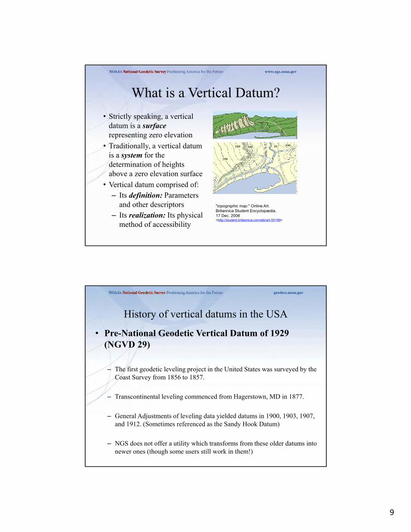
What is a Vertical Datum?
• Strictly speaking, a vertical datum is a surfacerepresenting zero elevation
• Traditionally, a vertical datum is a system for the determination of heights above a zero elevation surface
• Vertical datum comprised of:– Its definition: Parameters
and other descriptors – Its realization: Its physical
method of accessibility
"topographic map." Online Art. Britannica Student Encyclopædia. 17 Dec. 2008 <http://student.britannica.com/ebi/art-53199>
History of vertical datums in the USA
• Pre-National Geodetic Vertical Datum of 1929 (NGVD 29)
– The first geodetic leveling project in the United States was surveyed by the Coast Survey from 1856 to 1857.
– Transcontinental leveling commenced from Hagerstown, MD in 1877.
– General Adjustments of leveling data yielded datums in 1900, 1903, 1907, and 1912. (Sometimes referenced as the Sandy Hook Datum)
– NGS does not offer a utility which transforms from these older datums into newer ones (though some users still work in them!)
10
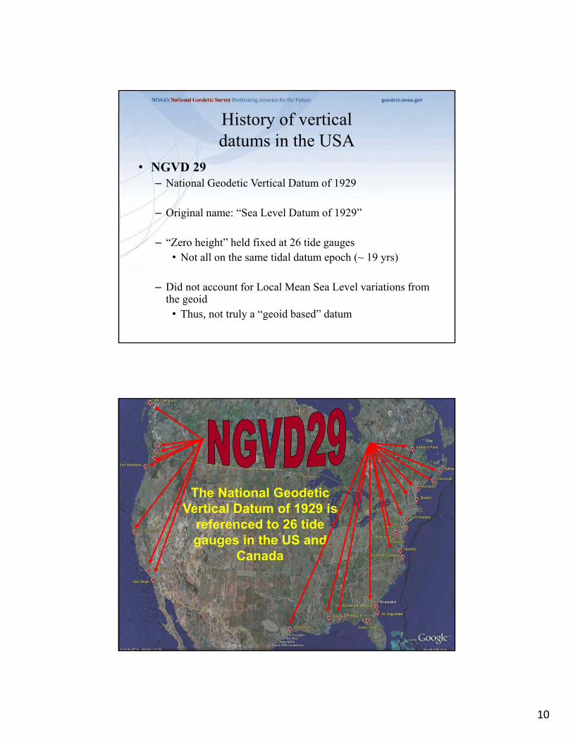
History of vertical datums in the USA
• NGVD 29– National Geodetic Vertical Datum of 1929
– Original name: “Sea Level Datum of 1929”
– “Zero height” held fixed at 26 tide gauges• Not all on the same tidal datum epoch (~ 19 yrs)
– Did not account for Local Mean Sea Level variations from the geoid
• Thus, not truly a “geoid based” datum
The National Geodetic Vertical Datum of 1929 is
referenced to 26 tide gauges in the US and
Canada

11
Current Vertical Datum in the USA
• NAVD 88: North American Vertical Datum of 1988
• Definition: The surface of equal gravity potential to which orthometric heights shall refer in North America*, and which is 6.271 meters (along the plumb line) below the geodetic mark at “Father Point/Rimouski” (NGSIDB PID TY5255).
• Realization: Over 500,000 geodetic marks across North America with published Helmert orthometric heights, most of which were originally computed from a minimally constrained adjustment of leveling and gravity data, holding the geopotential value at “Father Point/Rimouski” fixed.
Father Point Lighthouse, Quebec *Not adopted in Canada
History of vertical datums in the USA
• NAVD 88– North American Vertical Datum of 1988
– One height held fixed at “Father Point” (Rimouski, Canada)
– …height chosen was to minimize 1929/1988 differences on USGS topo maps in the eastern U.S.
– Thus, the “zero height surface” of NAVD 88 wasn’t chosen for its closeness to the geoid (but it was close…few decimeters)

12
History of vertical datums in the USA
• NAVD 88 (continued)
– Use of one fixed height removed local sea level variation problem of NGVD 29
– Use of one fixed height did open the possibility of unconstrained cross-continent error build up
– H=0 surface of NAVD 88 was supposed to be parallel to the geoid…(close again)
4 cm
125 cm
70 cm
85 cm 102 cm
NGVD 29Referenced to 26 Tide Gages
NAVD 88Referenced to 1 Tide Gage
(Father’s Point)
NAVD88 minus LMSL(1960-1978)
-23 cm
-23 cm
-11 cm
-11 cm

13
Types Uses and History of Geoid Height Models
• Gravimetric (or Gravity) Geoid Height Models– Defined by gravity data crossing the geoid
– Refined by terrain models (DEM’s)
– Scientific and engineering applications
• Composite (or Hybrid) Geoid Height Models– Gravimetric geoid defines most regions
– Warped to fit available GPSBM control data
– Defined by legislated ellipsoid (NAD 83) and local vertical datum (NAVD 88, PRVD02, etc.)
– May be statutory for some surveying & mapping applications
GPSBM1996: 2,951total 0 Canada STDEV ≈ 5 cm (2σ)

14
GPSBM2003: 14,185 total 579 Canada STDEV 4.8 cm (2 σ)
GPSBM1999: 6,169 total 0 Canada STDEV 9.2 cm (2σ)
GPSBM2009: 18,398 STDEV 2.8 cm (2σ)

15
GGPSBM2012A: 23,961 (CONUS) STDEV 3.4 cm (2σ)499 (OPUS on BM)574 (Canada)177 (Mexico)
489 in VT
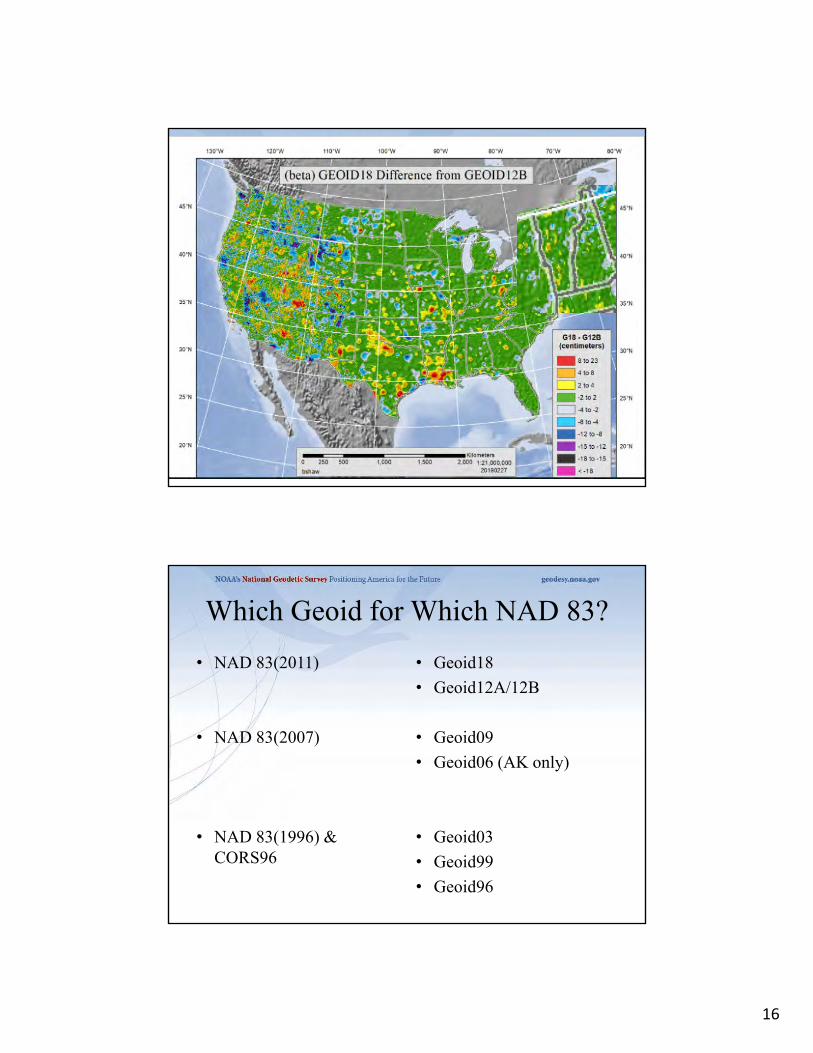
16
Which Geoid for Which NAD 83?
• NAD 83(2011)
• NAD 83(2007)
• NAD 83(1996) & CORS96
• Geoid18
• Geoid12A/12B
• Geoid09
• Geoid06 (AK only)
• Geoid03
• Geoid99
• Geoid96

17
Problems with NAD 83 and NAVD 88
NAD 83 is not as geocentric as it could be (approx. 2 m) Positioning Professionals don’t see this - Yet
NAD 83 is not well defined with positional velocities
NAVD 88 is realized by passive control (bench marks) most of which have not been re-leveled in at least 40 years.
NAVD 88 does not account for local vertical velocities (subsidence and uplift) Post glacial isostatic readjustment (uplift)
Subsurface fluid withdrawal (subsidence)
Sediment loading (subsidence)
Sea level rise in CT (0.84 ft – 0.92 ft per 100 years) Bridgeport, CT 2.88 mm/yr (0.009 ft/yr) 1964-2015
New London, CT 2.55 mm/yr (0.008 ft/yr) 1938-2015
GRACE – Gravity Recovery and Climate Experiment
18
35
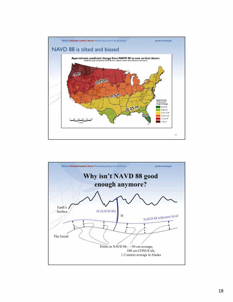
NAVD 88 is tilted and biased
Earth’sSurface
The Geoid
H (NAVD 88)
Errors in NAVD 88 : ~50 cm average, 100 cm CONUS tilt,
1-2 meters average in Alaska
Why isn’t NAVD 88 goodenough anymore?

19
Why replace NAVD 88 and NAD 83?
• ACCESS!– easier to find the sky than a 60-year-old bench mark
– GNSS equipment is cheap and fast
• ACCURACY!– easier to trust the sky than a 60-year old bench mark
– immune to passive mark instability
• GLOBAL STANDARDS!– systematic errors of many meters across the US
– aligns with GPS, international efforts
– aligns with Canada, Mexico37
ITRF is now mature
April 24, 2017

20
The National Geodetic Survey 10 year planMission, Vision and Strategy
2008 – 2018, 2013-2023http://www.ngs.noaa.gov/INFO/NGS10yearplan.pdf
• Official NGS policy as of Jan 9, 2008– Modernized agency– Attention to accuracy– Attention to time-changes– Improved products and services– Integration with other fed missions
• 2022 Targets: – NAD 83 and NAVD 88 re-defined– Cm-accuracy access to all
coordinates– Customer-focused agency– Global scientific leadership
21
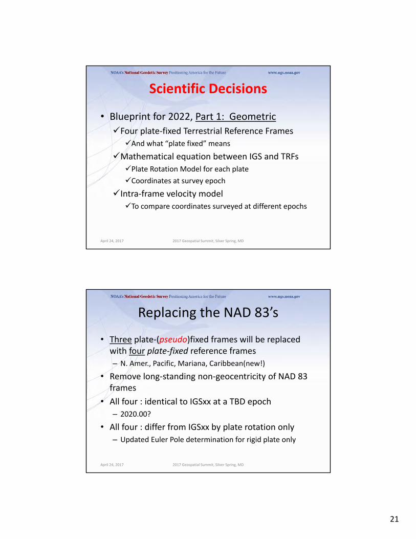
Scientific Decisions
• Blueprint for 2022, Part 1: Geometric
Four plate‐fixed Terrestrial Reference Frames
And what “plate fixed” means
Mathematical equation between IGS and TRFs
Plate Rotation Model for each plate
Coordinates at survey epoch
Intra‐frame velocity model
To compare coordinates surveyed at different epochs
April 24, 2017 2017 Geospatial Summit, Silver Spring, MD
Replacing the NAD 83’s
April 24, 2017 2017 Geospatial Summit, Silver Spring, MD
• Three plate‐(pseudo)fixed frames will be replaced with four plate‐fixed reference frames
– N. Amer., Pacific, Mariana, Caribbean(new!)
• Remove long‐standing non‐geocentricity of NAD 83 frames
• All four : identical to IGSxx at a TBD epoch
– 2020.00?
• All four : differ from IGSxx by plate rotation only
– Updated Euler Pole determination for rigid plate only
22
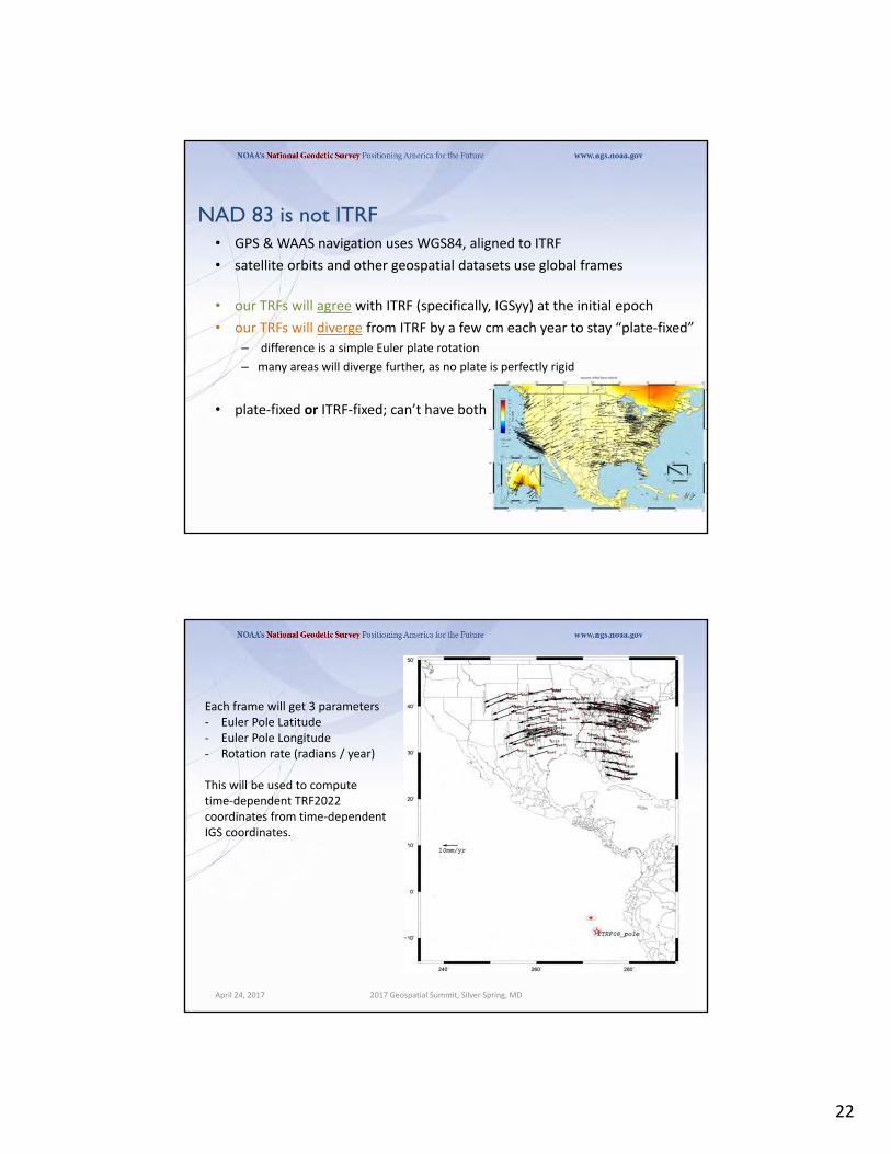
• GPS & WAAS navigation uses WGS84, aligned to ITRF
• satellite orbits and other geospatial datasets use global frames
• our TRFs will agree with ITRF (specifically, IGSyy) at the initial epoch
• our TRFs will diverge from ITRF by a few cm each year to stay “plate‐fixed”
– difference is a simple Euler plate rotation
– many areas will diverge further, as no plate is perfectly rigid
• plate‐fixed or ITRF‐fixed; can’t have both
NAD 83 is not ITRF
April 24, 2017 2017 Geospatial Summit, Silver Spring, MD
Each frame will get 3 parameters‐ Euler Pole Latitude‐ Euler Pole Longitude‐ Rotation rate (radians / year)
This will be used to computetime‐dependent TRF2022 coordinates from time‐dependentIGS coordinates.

23
Names
The Old:NAD 83(2011)
NAD 83(PA11)
NAD 83(MA11)
The New:The North American Terrestrial Reference Frame of 2022
(NATRF2022)
The Caribbean Terrestrial Reference Frame of 2022 (CTRF2022)
The Pacific Terrestrial Reference Frame of 2022 (PTRF2022)
The Mariana Terrestrial Reference Frame of 2022
(MTRF2022)
April 24, 2017 2017 Geospatial Summit, Silver Spring, MD
Scientific Decisions!!
• Blueprint for 2022, Part 2: Geopotential
Global 3‐D Geopotential Model (GGM)
Will contain all GRAV‐D data
Able to yield any physical value on/above surface
Special high‐resolution geoid, DoV and surface gravity products consistent with GGM
Not global: NA/Pacific, American Samoa, Guam/CNMI
Time‐Dependencies
Geoid monitoring service Impacts of deglaciation, sea level rise, earthquakes, etc
April 24, 2017 2017 Geospatial Summit, Silver Spring, MD

24
April 24, 2017 2017 Geospatial Summit, Silver Spring, MD
GEOID2022 (et al) over the North America/Pacific/Caribbean/Central America/Greenland region will range from 0 to 90 latitude and from 170 to 350 longitude.
GEOID2022 (et al) over Guam/CNMI:11‐22, 143‐148
GEOID2022 (et al) over American Samoa:‐16 to ‐10, 186‐193
Names
The Old:NAVD 88PRVD 02VIVD09ASVD02NMVD03GUVD04IGLD 85IGSN71GEOID12BDEFLEC12B
The New:The North American-Pacific Geopotential Datum of 2022 (NAPGD2022)
- Will include GEOID2022
April 24, 2017 2017 Geospatial Summit, Silver Spring, MD
OrthometricHeights
NormalOrthometricHeights
DynamicHeights
Gravity
GeoidUndulations
Deflections ofthe Vertical

25
NAVD 88 is not alone
April 24, 2017 2017 Geospatial Summit 49
• NAVD 88 North American Vertical Datum of 1988
• PRVD02 Puerto Rico Vertical Datum of 2002
• ASVD02 American Samoa Vertical Datum of 2002
• NMVD03 Northern Marianas Vertical Datum of 2003, 3 each
• GUVD04 Guam Vertical Datum of 2004
• VIVD09 Virgin Islands Vertical Datum of 2009, 3 each
• Hawaii … Hawaiian Islands Vertical Datum (coming soon)
• various local datums, as national datum is inaccessible
• IGLD 85 International Great Lakes Datum of 1985
• IGSN71 gravity dataset
• GEOID12B geoid undulations
• DEFLEC12B deflection of the vertical
Height-Mod means More Marks?

26
Differential Leveling
GNSS + …
HeightModernization
‐faster‐cheaper
Height Modernization
How accurate is a GPS-derived Orthometric Height?
• Relative (local) accuracy in ellipsoid heights between adjacent points can be better than 2 cm, at 95% confidence level
• Network accuracy (relative to NSRS) in ellipsoid heights can be better than 5 cm, at 95% confidence level
• Accuracy of orthometric height is dependent on accuracy of the geoid model – Currently NGS is improving the geoid model with more data, i.e. Gravity and GPS observations on leveled bench marks from Height Mod projects
• Geoid12a can have an uncertainty in the 2-5 cm range.

27
OPUS Static reliably addresses the more historically conventional requirements for GPS data processing. It typically yields accuracies of:
1 – 2 cm horizontally2 – 4 cm vertically
However, there is no guarantee that this stated accuracy will result from any given data set. Confirming the quality of the OPUS solution remains your responsibility. That’s the “price” for automated processing.
53
How Good Can I Do With OPUS Static?
• 4‐7 mm differential ellipsoid height accuracy in GSVS11
• New ellipsoid height accuracy estimates will be included in a planned update to HTMOD guidelines for a number of GNSS techniques.
RMSE of OPUS-S, OPUS-RS
Gillins (2019)

28
• Using GNSS can be:– Faster
– Cheaper
– More accurate?
• To use GNSS, we need a good geoid model
GNSS vs Leveling

29
The ellipsoid, the geoid, and you
Earth surface
Orthometric height, H
Geoid height, NG
Ellipsoid height, h
Deflection of the vertical
Mean sea level
h ≈ H + NG
Note: Geoid height is negative everywhere in the coterminous US
h = H + NG
You are here
(but it is positive in most of Alaska)
• Replace the Vertical Datum of the USA by 2022 (at today’s funding) with a gravimetric geoid accurate to 1 cm
• Orthometric heights accessed via GNSS accurate to 2 cm
• Three thrusts of project:
– Airborne gravity survey of entire country and its holdings
– Long‐term monitoring of geoid change
– Partnership surveys
• Working to launch a collaborative effort with the USGS for simultaneous magnetic measurement
Gravity for the Redefinition of the American Vertical Datum (GRAV‐D)
Gravity and Heights are
inseparably connected

30
Gravity Survey Plan
• National Scale Part 1
– Predominantly through airborne gravity
– With Absolute Gravity for ties and checks
– Relative Gravity for expanding local regions where airborne shows significant mismatch with existing terrestrial
Airborne Gravity Current Coverage
http://www.ngs.noaa.gov/GRAV-D/data_products.shtml
CompleteProcessingCollectingPlanned
Data Block Status
As of Oct 2018

31
Performance MetricFor Airborne Surveys
• Measure: Percentage of the U.S. and its territories with GRAV‐D data available to support a 1 cm geoid supporting 2 cm orthometric heights.
FY09 Baseline
Targets vs Actual
FY10 FY11 FY12 FY13 FY14 FY15 FY16 FY17 FY18 FY19 FY20 FY21 FY22
6.14% 7.5% 12% 20% 28% 36% 45% 53% 62% 70% 79% 87% 96%100% and Implement
6.14 8% 15% 24% 31% 38% 45% 55% 64% 72%
October 27, 2017
GRAV‐D Aircraft
Bureau of Land Management Pilatus PC‐12
Fugro Cessna Conquest
Aurora Flight Sciences Centaur Optionally Piloted Aircraft
NOAA P‐3 (background)NOAA Turbo Commander (foreground)
Dynamic Aviation King Air 200T
Naval Research Laboratory King Air RC‐12
Fugro King Air E‐90A

32
Ship gravity
Terrestrial gravity
New Orleans
20-100 km gravity gaps along coast
• Field is not sampled uniformly
• Data range in age and quality, some w/o metadata
• Some surveys have systematic errors
• Data gaps in littoral areas
Problems with Gravity Holdings
Validating Geoid Accuracy
• NGS planed 3 surveys to validate the accuracy of the gravimetric geoid model
– GSVS11
• 2011; Low/Flat/Simple: Texas; Done; Success!
– GSVS14
• 2014; High/Flat/Complicated: Iowa; Field work Complete
– GSVS17
• 2016 ‐ 2017; High/Rugged/Complicated: Colorado

33
Objective of the GSVSs• How do we know that GRAV‐D is working?
• The Geoid Slope Validation Surveys (GSVSs) use high precision, high resolution (~1.5km spacing), ground‐based survey techniques to determine the shape of the geoid consistently along a large (~300km) distance.
• This allows for the direct comparison of the geoid shape predicted by various, gravity‐based geoid models.
• This also allows for a quantification of the airborne gravity’s contribution to the improvement of these models.
February 8, 2017 2017 Geospatial Summit, Silver Spring MD
Objective of the GSVSs (cont.)Why compare the shape of the models?
Rather than using “absolute” values of the geoid at specific locations to compare models, it is actually more useful to look at the changes in the shape of the geoid over various distance scales (i.e. looking at the slope between various pairs of survey points separated by 1, 2, 5, 10, 20, 50, 100, 200 km, etc.) .
Hence the name…
Example of slopes over various distance scales:Every 1 interval
Every 2 intervalsEvery 3 intervals
Every 4 intervals
February 8, 2017 2017 Geospatial Summit, Silver Spring MD

34
Choosing the Place and Time for a New Survey• Criteria:
– Significantly exceed 100 km
– Under existing GRAV‐D data
– Avoid trees and woods
– Along major roads
– Cloud‐free nights
– No major bridges along the route
– Low elevations
– Significant geoid slope
– Inexpensive travel costs12/9/2011 American Geophysical Union Fall Meeting 67
GSVS Survey Techniques7
• Survey techniques employed:
• Bechmarks installed ~1.5km• Leveling• Absolute/Relative Gravity
• Vertical Gravity Gradient
• Long‐session GPS• Deflection of Vertical
February 8, 2017 2017 Geospatial Summit, Silver Spring MD

35
Leveling and Gravity• The entire line was leveled (double‐run). Geodetic heights
provided at each benchmark.
• Leveling and gravity are both needed for orthometric height determination. Usually gravity is modeled, but in this case was actually measured at every point.
– Relative gravity and vertical gravity gradient at every benchmark
– Absolute gravity (A10 and/or FG5) at ~every 10th benchmark8
February 8, 2017
Long Period GPS
• Calibrated, fixed‐height antennas, all identical models
• In Texas 2011:
– 20 complete sets of equipment (2 parties, 10 sets each)
– Each party observed 10 new stations each day
– 20 hours of observation each day
– Project processed with OPUS Projects9February 8, 2017 2017 Geospatial Summit, Silver Spring MD

36
• Full antenna recalibration check before survey
• Each fixed height tripod height
measured before and after
• 20 complete sets of equipment ‐
2 parties (10 sets each)
• Each party observe 5 new and 5
repeat stations each day
• 30 observation days
• Project processed with OP
Campaign GPS
ID before after a ‐ b avg.
A 2.0028 2.0029 0.0001 2.0029
B 2.0019 2.0018 ‐0.0001 2.0018
C 2.0005 2.0002 ‐0.0003 2.0004
D 2.0079 2.0079 0.0000 2.0079
E 2.0011 2.0010 ‐0.0001 2.0010
F 1.9999 1.9998 ‐0.0001 1.9998
G 2.0006 2.0009 0.0003 2.0008
H 2.0016 2.0017 0.0001 2.0017
I 2.0020 2.0020 0.0000 2.0020
J 2.0041 2.0041 0.0000 2.0041
K 2.0003 2.0004 0.0001 2.0003
L 2.0010 2.0007 ‐0.0003 2.0008
M 2.0000 2.0002 0.0002 2.0001
N 1.9964 1.9963 ‐0.0001 1.9963
O 2.0005 2.0005 0.0000 2.0005
P 2.0003 2.0002 ‐0.0001 2.0002
Q 2.0024 2.0029 0.0005 2.0027
R 1.9999 1.9999 0.0000 1.9999
S 2.0052 2.0052 0.0000 2.0052
T 2.0026 2.0023 ‐0.0003 2.0024
U 2.0031 2.0031 0.0000 2.0031
V 1.9995 1.9995 0.0000 1.9995
W 2.0002 2.0003 0.0001 2.0003
X 2.0020 2.0022 0.0002 2.0021
Y 2.0053 2.0053 0.0000 2.0053
Z 2.0016 2.0014 ‐0.0002 2.0015
The “Dimple‐ometer”

37
Deflection of the Vertical (DoV)• Measure the slope of the geoid directly!
• Precision tilt meters provide alignment “level” to the geoid.
• Celestial almanacs provide predicted alignment with star field (relative to ellipsoid).
• The difference between the two vectors (broken into orthogonal components) are the Deflections of the Vertical (or “slopes”).
• In Iowa 2014:– 228 stations (204 official points, 11 redundant
observations, 3 reobservations)
– 31 nights
– 7 stations/night
– Observing with Swiss CODIAC (COmpact DIgital Astrometric Camera)
38
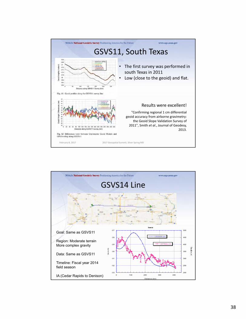
GSVS11, South Texas
• The first survey was performed in south Texas in 2011
• Low (close to the geoid) and flat.
Results were excellent!
"Confirming regional 1 cm differential geoid accuracy from airborne gravimetry:
the Geoid Slope Validation Survey of 2011", Smith et al., Journal of Geodesy,
2013.
February 8, 2017 2017 Geospatial Summit, Silver Spring MD
GSVS14 Line
-33
-32
-31
-30
-29
-28
-27
200
250
300
350
400
450
500
0 100 200 300 400
Iowa
USGG09 (m)
SRTM3s (m)
Distance (km)
Goal: Same as GSVS11
Region: Moderate terrainMore complex gravity
Data: Same as GSVS11
Timeline: Fiscal year 2014 field season
IA (Cedar Rapids to Denison)

39
GSVS17 Colorado• The third (and likely final) GSVS will take place along US160, from
Durango to Walsenburg, in southern Colorado.
• High elevation and rugged topography. “Worst case” for geoid modeling.
• Variation from 6,000’ (MSL) to 11,000’, over two passes.
12
February 8, 2017 2017 Geospatial Summit, Silver Spring MD
Differences with GSVS17
• Numerous “extra” bench marks had to be installed for leveling accuracy purposes (very steep terrain in some sections).
• Absolute gravity (A10) and quadratic (3 tier) gravity gradients will be measured at all benchmarks.
• Topographic corrections are being developed to aid in field DoV quality control as well as post-survey geoid modeling.
February 8, 2017 2017 Geospatial Summit, Silver Spring MD
40
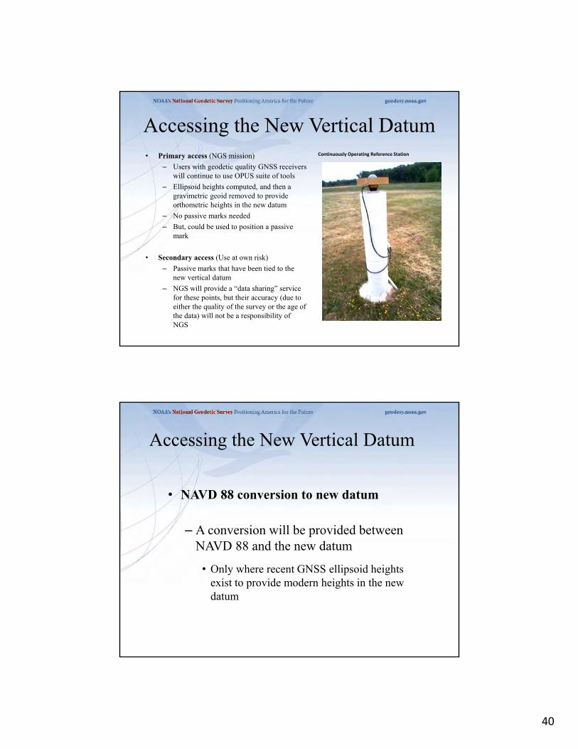
Accessing the New Vertical Datum• Primary access (NGS mission)
– Users with geodetic quality GNSS receivers will continue to use OPUS suite of tools
– Ellipsoid heights computed, and then a gravimetric geoid removed to provide orthometric heights in the new datum
– No passive marks needed
– But, could be used to position a passive mark
• Secondary access (Use at own risk)
– Passive marks that have been tied to the new vertical datum
– NGS will provide a “data sharing” service for these points, but their accuracy (due to either the quality of the survey or the age of the data) will not be a responsibility of NGS
Continuously Operating Reference Station
• NAVD 88 conversion to new datum
– A conversion will be provided between NAVD 88 and the new datum
• Only where recent GNSS ellipsoid heights exist to provide modern heights in the new datum
Accessing the New Vertical Datum

41
Predicted Changes in 2022Vicinity of Montpelier, VT
(Computed for station VCAP, pid AF9563)
‐0.368m (‐1.21ft)
HORIZONTAL = 1.25 m (4.1 ft)ELLIPSOID HEIGHT = - 1.15 m (- 3.8 ft)
Predicted with HTDP
metadata to the rescue
• your positional metadata should include:– Datum, epoch, projection/zone, source, method,
accuracy estimate, date of observation, geoid model, UNITS!!
• these will facilitate transforming from current to new datum
• maintaining your original survey data will provide more accurate results

42
A New State Plane Coordinate System
• State Plane Coordinate System of 2022 (SPCS2022)– Referenced to 2022 Terrestrial Reference Frames (TRFs)
– Based on same reference ellipsoid as SPCS 83 (GRS 80)
– Same 3 conformal projection types as SPCS 83 and 27:
83
Transverse Mercator (TM)
Oblique Mercator (OM)
Lambert Conformal Conic (LCC)
Deadlines for SPCS2022 input
Federal Register Notice (FRN)• Announcement and public comments
– On draft SPCS2022 policy & procedures– On “special purpose” zones
SPCS2022 Procedures (draft)• Consensus input per SPCS2022 procedures
– Requests for designs done by NGS– Proposals for designs by contributing partners
• Submittal of approved designs– Proposal must first be approved by NGS– Designs must be complete for NGS to review
• Later requests will be for changes to SPCS2022
[email protected] August 31, 2018
Anyone can comment!
[email protected] 31, 2020 for requests and proposals
byMarch 31, 2021 for submittal of approveddesigns
State stakeholders only!

43
85
geodesy.noaa.gov/SPCS/
Summary of main things that did NOT change• Policy
– Limited to LCC, TM, and OM projections– Zones designed to reduce distortion at ground– Default zones designed by NGS if no consensus input – Parameters in meters, but feet allowed for output
• Procedures– Stakeholders must submit requests/proposals– 1-parallel LCC and local OM projection definitions– Specified a linear distortion design criterion– Limit NGS designs to minimum of ±50 ppm– 50 km min zone size for height range of 250 m or less
86
SPCS2022 Policy & ProceduresSPCS2022 Policy & Procedures

44
Summary of main changes• Allow “special use” zones
– But only for zone areas in more than 1 state
• NGS will design statewide zone for every state– Also will design default zones if no consensus request
for something different from state stakeholders
• Allow max of 3 layers (1 statewide + 2 multi-zone)– But most states will have 1 or 2 layers
• Added requirement that all zones be unique• Require positive east longitudes
87
Changes to SPCS2022 PoliciesChanges to SPCS2022 Policies
SPCS2022 stakeholders
• State groups that formally interface with NGS– Departments of transportation– Cartographer/GIS office– Professional surveying, engineering, GIS societies– Colleges/universities with geospatial curriculum
• Can submit requests and proposals for designs– Requests are for designs by NGS– Proposals are designs by stakeholders
• Stakeholder input must be unanimous
88

45
Grid distance > ellipsoid distance
Projectionaxis
Linear distortion with respect to ellipsoid
Grid distance < ellipsoid distance
Ellipsoid distance
Ellipsoid distance
Projection surface (secant)
This design approach used for SPCS 27 and 83
(minimizes distortion with respect to ellipsoid)
Ellipsoid surface
Grid distance < ellipsoid distance< ground distance
Grid distance > ellipsoid distance< ground distance
Ellipsoid surface Ellipsoid
distance
Topographic surface
Horizontal ground
distance
Ellipsoid distance
> ellipsoid distanceand
> grid distance
Linear distortion with respect to topographic surface
Projection surface (secant)
This design approach used for SPCS 27 and 83
(minimizes distortion with respect to ellipsoid)
Projectionaxis
46
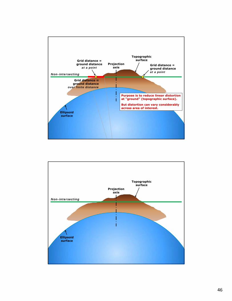
Projectionaxis
“Non-intersecting” conformal map projection
Non-intersecting
Ellipsoid surface
Purpose is to reduce linear distortion at “ground” (topographic surface).
But distortion can vary considerably across area of interest.
Grid distance = ground distance
at a pointGrid distance = ground distance at a point
Grid distance ≈ ground distance
over finite distance
Topographic surface
Projectionaxis
“Non-intersecting” conformal map projection
Non-intersecting
Ellipsoid surface
Topographic surface
47
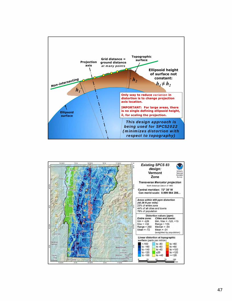
Projectionaxis
Changing projection axis to reduce distortion variation
Ellipsoid surface
h2
h1
Grid distance = ground distance at many points
Only way to reduce variation in distortion is to change projection axis location.
IMPORTANT: For large areas, there is no single defining ellipsoid height, h, for scaling the projection.
Ellipsoid height of surface not
constant: h1 ≠ h2
Topographic surface
This design approach is being used for SPCS2022
(minimizes distortion with respect to topography)

48
NGS Coordinate Conversion and Transformation Tool (NCAT)

49
NCAT Output
X, Y, Z
USNG UTM
SPC
, , h
X, Y, Z
USNG UTM
SPC
, , h
X, Y
, Z
USN
GUTM
SPC
, , hRegion: CONUS
NADCON 5 connections in RED
USSD
NAD 27
NAD 83 (1986)
NAD 83 (2011)
NAD 83 (NSRS2007)
NAD 83 (FBN)NAD 83 (HARN)
2022
50
NGS’ 2nd Reprocessing Campaign
● IGS08 coordinates and velocities were released in 2011 through the first reprocessing campaign
● Need for the new coordinates and velocities due to:○ The geophysical activities (earthquakes) in some area,○ The equipment changes,○ New CORS stations and 6 more years of data since 2011, and○ New frame released (IGS14)
● Model update since Repro1 campaign○ IGb08 reference frame model○ Updated IGS08 absolute antenna calibration○ Generally implement IERS 2010 convention
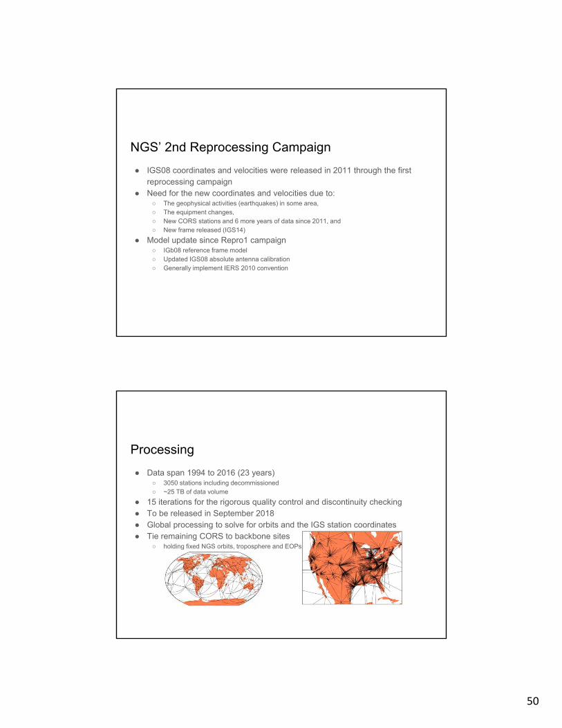
Processing
● Data span 1994 to 2016 (23 years)○ 3050 stations including decommissioned○ ~25 TB of data volume
● 15 iterations for the rigorous quality control and discontinuity checking ● To be released in September 2018● Global processing to solve for orbits and the IGS station coordinates● Tie remaining CORS to backbone sites
○ holding fixed NGS orbits, troposphere and EOPs.
51
• Foundation for all NGS data of the future– Spatial Database
– Hold all data from existing Integrated DataBase
– Hold all future data generated by and for NGS
– Capable of representing everything in 4-D
– Be easily loadable by NGS personnel
– Be easily retrievable by NGS and the public
– Capable of permanently storing all of NGS survey data (future and historic)
– Capable of tracking all changes to the data
Modernized Database
• More than just new “datasheets”
• Ability to deliver dynamic data
• Ability to generate time-based data
• Ability for user to customize output
Data Delivery System (DDS)(Working Group)
52
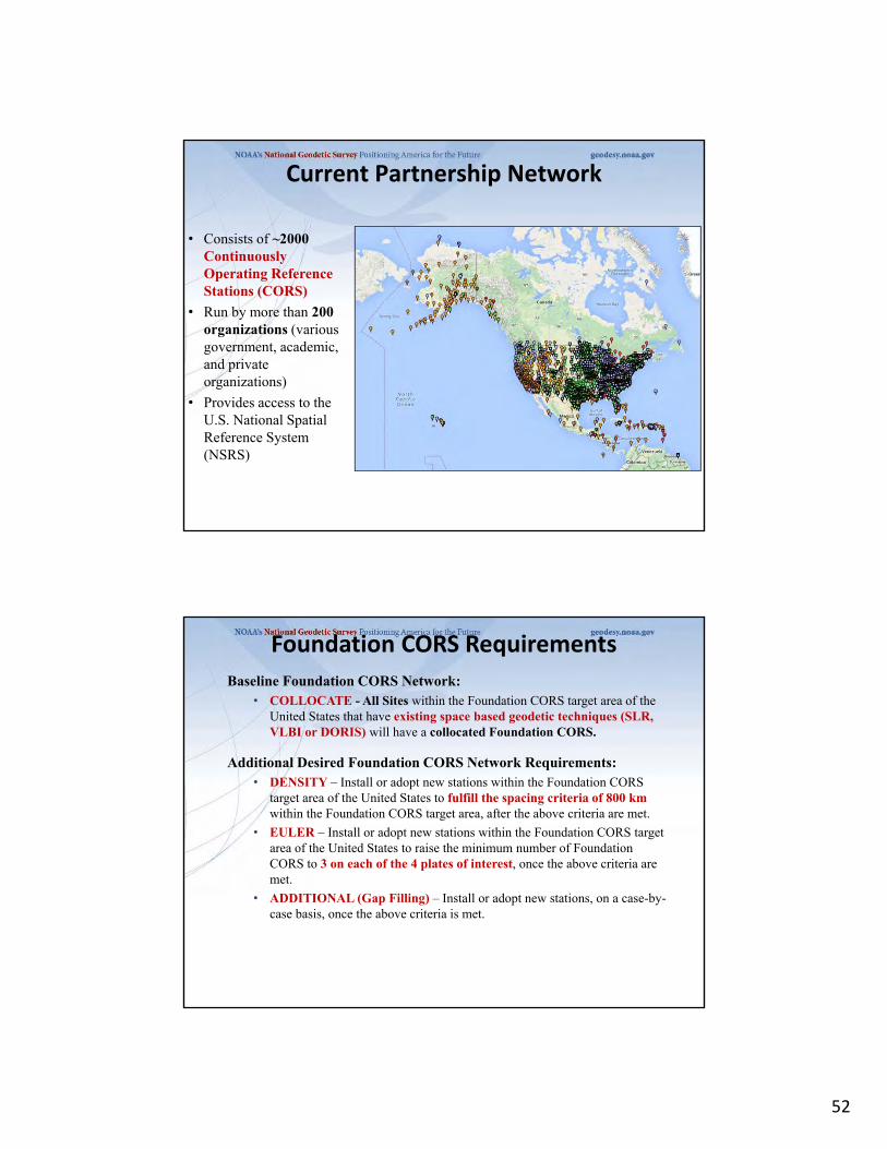
• Consists of ~2000Continuously Operating Reference Stations (CORS)
• Run by more than 200 organizations (various government, academic, and private organizations)
• Provides access to the U.S. National Spatial Reference System (NSRS)
Current Partnership Network
Foundation CORS Requirements
Baseline Foundation CORS Network:• COLLOCATE - All Sites within the Foundation CORS target area of the
United States that have existing space based geodetic techniques (SLR, VLBI or DORIS) will have a collocated Foundation CORS.
Additional Desired Foundation CORS Network Requirements:• DENSITY – Install or adopt new stations within the Foundation CORS
target area of the United States to fulfill the spacing criteria of 800 kmwithin the Foundation CORS target area, after the above criteria are met.
• EULER – Install or adopt new stations within the Foundation CORS target area of the United States to raise the minimum number of Foundation CORS to 3 on each of the 4 plates of interest, once the above criteria are met.
• ADDITIONAL (Gap Filling) – Install or adopt new stations, on a case-by-case basis, once the above criteria is met.

53
Future “Foundation CORS” Network
Project Implementation
• Phase 1 – Incorporate ~28 existing partner and NGS CORS into Foundation CORS network
• Phase 2 – Upgrade ~7 existing CORS to GNSS to meet Foundation CORS requirements
• Phase 3 – Construct ~8 new Foundation CORS

54
-27
00
-25
00
-15
00
-10
00
-50
0 0
50
0
75
0
10
00
12
50
15
00
17
00
17
50
18
50
19
00
19
77
19
89
20
00
20
10
20
17
20
30
POSITIONING TECHNOLOGY-A CARTOON GRAPH
TECHNOLOGY
YEAR
0.5' SAT IMAGERY,MOBILE TERR. LASER SCANNING, 0.10' AERIAL MAPPING, NATIONAL NETWORKS, 24/7/365 SAT. COVERAGE,Drones
GNSS‐ GLONASS, GALILEO,
COMPASS/BEIDOU,INDOOR POSITIONING,
PPP
GPS
RTK
RTN
TOTAL STATIONCOMPASS
THEODOLITESTICKS AND STRINGS
GISTHE CHANGE FROM LABOR INTENSIVE TO TECHNOLOGY!
“Human knowledge is doubling every 10 years. The scientific knowledge produced between 1987 and 1997 is greater than that produced in all mankind’s history”.
Michio Kaku‐ renowned theoretical physicist
Precision vs. Accuracy measurement from RTN correctors
More questions?• Is there systematic bias,
multipath, and atmospheric errors to overcome? Always some!
• How is the accepted true (accurate) position determined?
Accurate ‐Accepted truth
Courtesy www.calguns.net

55
RTN Measurement Precision
Typical (normal) RTN precisions at the 95% confidence level:
•horizontal 2‐3 cm•vertical (ellipsoid height) 3‐5 cm•orthometric heights 5‐7 cm (typical‐using the NGS hybrid geoid model)
Exceptional RTN derived precisions at the 95% confidence level at the limit of RT technology:
•horizontal: ≤ 1 cm•vertical (ellipsoid height) ≤ 1 cm•orthometric heights ≤ 2 cm
http://www.geodesy.noaa.gov/PUBS_LIB/NGS.RTN.Public.v2.0.pdf
110
Real-Time Kinematic (RTK) Surveying
Conventional RTK• Stationary single “base” station• Transmits precise coordinates and
GNSS observables to moving “rover”
• < 10-20 km baseline lengthApplications
• Survey engineering• Mobile mapping• Precision agriculture • Mining• Construction
Base Rover
www.steckbeck.netwww.positionpartners.com.au
www.gcfarm.comwww.alberding.eu

56
RTK
112
Real-Time Networks• Network of GNSS base stations
• < 70 km spacing between base stations• < 40 km maximum baseline length
• Atmospheric and orbital corrections are transmitted to rover via mobile data link
(Janssen and Haasdyk 2011)

57
April 5, 2019113
RTN CorrectionsVirtual Reference Stations (VRS) Master-Auxiliary Concept (MAC)
VRS
(Landau et al. 2002)
RTN Base RTN Base
RTN Base
• Vector “tails” referenced to virtual base station
• Base station position is variable
• Vector “tails” connected to physical base station
• Base station position is fixed
(Leica 2005)
ControlCenter
Internal Cell Modem Connected to NTRIP Caster via internet
Bluetooth connection
GNSS Signals

58
116
Pros and Cons of RTNsBenefits Concerns
FAST. Could reduce field observations from several hours to just a few minutes
RTN may not be aligned with the National Spatial Reference System
Can evaluate data quality in real time
Ideally, survey should be tied to CORS network
Easy to obtain additional observations
More prone to multipathing errors
Only a single receiver (i.e., rover) is needed during a session
Baselines must be kept short (i.e., < 40 km)

59
Real Time Networks
How does Precision translate to Accuracy
• NGS Accuracy Classes defined by 2d horizontal, 1d vertical precision (Repeatability) at 95% per redundant observation set
Horizontal Resultant (pub-obs) Average Day1-Day2
0
0.01
0.02
0.03
0.04
0.05
0.06
0 10000 20000 30000 40000 50000 60000 70000
Distance (m)
(m)
RT1r
RT2r
RT3r
RT4r
dh (pub-obs) Average Day1-Day2
-0.03
-0.02
-0.01
0
0.01
0.02
0.03
0.04
0.05
0 10000 20000 30000 40000 50000 60000 70000
Distance (m)
(m)
RT1h
RT2h
RT3h
RT4h
2σ Horizontal 2σ Vertical
RT1 0.024663 0.020933
RT2 0.021754 0.023475
RT3 0.020684 0.027002
RT4 0.025223 0.027488

60
2 Sigma Horizontal and Vertical Precisions vs.TimeHorizontal Coeficient of Correlation = 0.899
Vertical Coeficient of Correlation = 0.947
y = 0.0347x-0.0965
R2 = 0.9946
y = 0.018x-0.1007
R2 = 0.9920
0.005
0.01
0.015
0.02
0.025
0.03
0 50 100 150 200
Length of Observation (Sec)
2-S
igm
a P
reci
sio
n (
m)
2-Sig H
2-Sig V
Power (2-Sig V)
Power (2-Sig H)
Conclusions(Based on this study only)
• Duration of observation only appears to improve field RMS – no apparent bearing on actual precision
• No apparent correlation between actual precision and:– Baseline Length– Number of SV’s– RDOP
• Most important factor is achieving good initialization.
• Small increase in accuracy (vertical) with longer observations (based on 2σ error estimates of all observers’ data)
• Horizontal and Vertical precisions can be about the same
• Good accuracy and precision is possible even with short occupations on long vectors
61
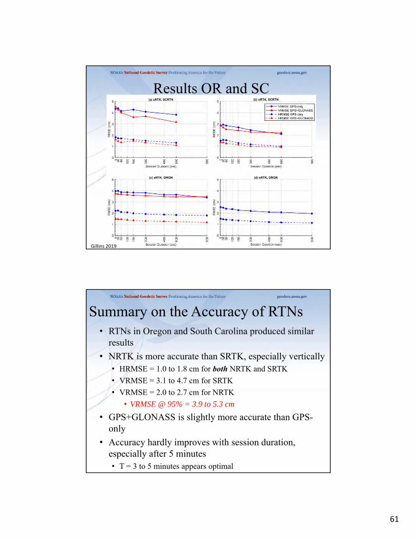
Results OR and SC
Gillins 2019
Summary on the Accuracy of RTNs• RTNs in Oregon and South Carolina produced similar
results
• NRTK is more accurate than SRTK, especially vertically• HRMSE = 1.0 to 1.8 cm for both NRTK and SRTK
• VRMSE = 3.1 to 4.7 cm for SRTK
• VRMSE = 2.0 to 2.7 cm for NRTK
• VRMSE @ 95% = 3.9 to 5.3 cm
• GPS+GLONASS is slightly more accurate than GPS-only
• Accuracy hardly improves with session duration, especially after 5 minutes• T = 3 to 5 minutes appears optimal

62
What can we use it for?
• Topo
• Asset Management
• LiDAR/Photo Control/QA/QC
• Flood Plain Mapping
• AVL
• Stakeout
• Change Detection/Analysis
• Boundary??
Not Here!!

63
• CHECK EQUIPMENT• COMMUNICATION• CONDITIONS• CONSTRAINTS(OR NOT)• COORDINATES• COLLECTION• CONFIDENCE
BEST METHODS FROM THE GUIDELINES:THE 7 “C’s”
https://www.ngs.noaa.gov/PUBS_LIB/NGSRealTimeUserGuidelines.v2.1.pdf
• Rover pole and Bubbles checked/adjusted
• Using bipod?
• Batteries
• Cables
• Phones, Modems, Antenna’s
Check Equipment

64
• Are you going to have cell coverage/WiFi?
• Know before you go…Check http://Vector.Vermont.gov
• Make sure GSM/CDMA antenna attached!!!
Communications
• Initialize in the open– Should be quick, RMS quick to stabilize
• Take observation– Recommend 1-3 minutes for “hard” points.
– Reinitialize• Different Day/Time
• Different Location?
• Different HI?
– Take redundant observation• Average position if spread is acceptable
Collection
65
Questions?
Dan MartinNortheast Regional Geodetic Advisor
ME, NH, VT, MA, CT, RI, NY, [email protected]
240-676-4762
Presentation will be available at:https://www.ngs.noaa.gov/web/science_edu/presentations_library/