session plasma accelerators / magnetoplasmadynamic (mpd) · plasma accelerators /...
TRANSCRIPT
Plasma Accelerators / Magnetoplasmadynamic (MPD)Thrusters
Ion Engines and, as we will see, Electrospray Thrusters are electrostatic devices, becausethe electrostatic forces that accelerate the ions (or droplets) are also directly felt by someelectrode, and this is how the structure receives thrust. The thrust density scales as 1
Session 19:
ε0E2,
2
where E is the field on the surface of the extractor electrode. This is the electrostaticpressure. Since ε = 8.854� 10�12
0 F/m and E is rarely more than 2000 V/m, we are limitedto electrostatic pressures of about 20 N/m2 (and due to various inefficiencies more like 1-2N/m2).
Hall thrusters occupy an intermediate position, and point the way to a higher thrust density.Ions accelerate electrostatically, but electrons, which see the same (and opposite) electrostaticforce, because the plasma is quasineutral, are essentially stopped (axially) by an interposedmagnetic field. Of course, the force is mutual, and so the electrons exert this force on themagnetic assembly (by means of the azimuthal Hall current they carry). In the end, then,the structure is pushed magnetically. To be more precise, we should say that most of theforce is magnetically transmitted. There is still an electrostatic field in the plasma, and sothere will be some electrostatic pressure acting on various surfaces. But because we madethe plasma quasineutral, these fields are much weaker than they are between the grids of anion engine, and it is a good thing we have the magnetic mechanism available. In fact, thethrust density of Hall thrusters is about 10 times higher than that of ion engines, despitethe weak electrostatic fields.
More generally, we can ask how much stronger can the force per unit area on some structurebe when it is transmitted magnetically as compared to electrostatically. As we will see indetail, the counterpart to the “electrostatic pressure” is the “magnetic pressure”, B2/2µ0,where B is the field strength and µ0 = 4π � 10�7 Hy/m is the permeability of vacuum.Without recourse to superconductive structures, B can easily be of the order of 0.1 Tesla(either using coils or permanent magnets), so B2/2µ N/m2
0 � 8,000 , or 400 times themaximum practical electrostatic pressure.
Thrusters that exploit these magnetic forces are called Electromagnetic (although they shouldbe called Magnetic by rights). The magnetic field can be external, i.e., supplied by coils andnot greatly modified by plasma currents, or it may be self-induced, when plasma currentsbecome large enough. They can also be steady (or at least slowly varying compared to plasmaflow time), or they can be varying very fast, so as to set up strong induced electromotiveforces (transformer effect). A few examples are:
� Magneto Plasma Dynamic (MPD) thrusters: The most powerful type, with self-induced magnetic fields, operates in steady (or quasi-steady) fashion, and can generatemulti-Newton thrust levels with a few cm diameter (compared to about 0.1 N for a 30cm ion engine, or for a 10 cm Hall thruster).
� Applied field MPD thrusters: Here currents are less strong, so the main part ofthe B field is external. Still steady or quasi-steady.
� Pulsed Plasma Thrusters (PPT): Pulsed Plasma Thrusters (PPT) are very similarin principle to self-field MPD, but they use a solid propellant (Teflon) which is ablatedduring each pulse of operation. These pulses last 10-20 µs only, but are just long
1
× −
× −
≈
•
•
•
~∂B~enough that induced emf fields (from r � E = � ) are still weak. Because of∂t
various practical (mostly thermal) issues, PPT thrusters are not very efficient (<10%),but they are simple and robust.
� Pulsed Inductive Thrusters (PIT): Here the emphasis is on very fast magneticrise time (1-10 µs) and the induced emf is used to break down the gas, ionize it, anddrive a closed current loop that exerts the desired magnetic force. They can be thoughtof as a one-turn transformer in which the secondary is a plasma ring; the repulsionbetween primary and secondary accelerates the plasma away and pushes the primarycoil forward. To avoid dissipating most of the power in Ohmic losses, the device mustbe fairly large (>0.5 m) and powerful (MW to GW of instantaneous power).
In this lecture we will have time only to explore the self-field MPD type. We begin withsome basic Physics.
Electromagnetic Forces on Plasmas - MPD Thrusters
~ ~For a charge q, moving at velocity ~v in an electric field E and magnetic field B, the Lorentzforce is,
~F = q(~E + ~v � ~B
)(1)
~Now, F cannot depend on the rectilinear motion of the observer. For non-relativistic veloc-~ ~ities, B is also independent of motion, and so is the scalar q. Therefore, the field E must be
~different as viewed from different frames of reference. Let E be the field in the laboratory~frame, and E 0 that in another frame moving at ~u relative to the first. Then we must have,
~E + ~v � ~ ~ ~B = E 0 + (~v � ~u)�B
so that,
~E 0 ~= E + ~u� ~B (2)
~ ~(in particular, for ~u = ~v the Lorentz force is seen to be purely electrostatic; i.e., F = qE 0).Most often the frame at ~u is chosen to be that moving at the mean mass velocity of theplasma.
Consider a plasma where there is a number density n thj of the j type of charged particle,
which has a charge qj and moves at mean velocity ~vj. The net Lorentz force per unit volumeis,
~f =∑
njqj
(~ ~E + ~vj �B
)(3)
j
and since the plasma is neutral∑
j njqj = 0, then,
2
∇ × −
•
×
× ′ − ×
′ ×
×
′
′
~f =
(∑njqj~vj
j
)� ~B (4)
But, by definition,
~j =∑
njqj~vj (5)j
where ~j is the current density vector (A/m2). So, finally,
~ ~f = ~j �B (6)
Notice that ~vj in Eq. (5) could be in any frame, including the plasma frame.
Ohm’s Law
In most cases, the dominant contribution to ~j (Eq. (5)) is from electrons, given their highmobility. In the plasma frame,
~j � ~je = �ene~ve (7)
Notice that ~ve is the electron mean velocity vector, not to be confused with the mean thermalspeed ce. The picture of electron motions is that of a very rapid, chaotic swarming ofelectrons back and forth (“going nowhere”), except that the whole swarm “slowly” drifts at~ve. Typically, j~vej � ce. Let us make a crude model of the motion of the electron swarm.The net force on it per unit volume is,
~ � �(~ ~fe ene E 0 + ~ve �B
)(8)
~where E 0 is used, since we are in the plasma frame.
In steady state, this is balanced by the drag force opposing motion of electrons relative tothe rest of the fluid, which we are assuming to be at rest, and whose particles have, bycomparison, only a very slow thermal motion. To evaluate this drag, let νe be the effectivecollision frequency per electron for momentum transfer. This frequency is defined suchthat in each collision with a particle of “the rest of the fluid,” the electron is, on average,scattered by 90�, so that its forward momentum is completely lost. The mean drag force perunit volume is,
~fdm
e = � eνenemeνe~ve = ~j (9)
e
Equating the sum of Eqs. (8) and (9) to zero,
e2n~ ej =
meνe
(~E 0 + ~ve � ~B
)=
e2nemeνe
~E 0 � e ~jmeνe
� ~B
Define the scalar conductivity,
3
×
×
≈ −
| | �
≈ − ′ ×
−
′ × ′ − ×
′
◦

e2neσ = (10)
meνe
and the Hall parameter,
eBβ =
~~and β = β
meνe
(B
(11)B
)
We can write the generalized Ohm’s law as,
~σE 0 = ~ ~j +~j �B (12)
~where, as given in Eq. (2), E 0 ~ ~= E+~u�B. As usual, the Hall parameter can be expected tobe high at low pressures and densities, where collisions are rare, and also at high magneticfield, where the gyro frequency is high. In many plasmas of interest in MHD or MPD, β � 1.
Electromagnetic Work
The rate at which the external fields do work on the charged particles can be calculated (perunit volume) as,
W =∑
njqjj
(~E + ~vj � ~B
)� ~vj =
∑~njqjE
j
� ~~vj = E �~j (13)
The magnetic field does not directly contribute to the total work, since the magnetic force is~orthogonal to the particle velocity; it does, however, modify E or ~j (depending on boundary
˙conditions), and through them it does affect W . This total work rate goes partly into heatingthe plasma (dissipation) and partly into pushing it (mechanical work). To see this, noticethat,
˙ ~W = E �~j =(~E 0 � ~u� ~B
)�~ ~j = E 0 �~j �
(~u� ~B
)�~ ~j = E 0 �~j +
(~ ~j �B
)� ~u
Also, using Ohm’s law,
1~E 0 �~j =σ
(~j +~j � ~β
)�~j =
j2
σ
Thus,
j2
W = ~+σ
(~j �B
)� ~u (14)
The second term of this expression is simply the rate at which the Lorentz force ~ ~j � Bdoes mechanical work on the plasma moving at ~u. The first term is always positive andis the familiar Joule heating (also called Ohmic heating) effect. Notice how the presenceof the magnetic field introduces the possibility of accelerating a plasma, in addition( )to the
voidable heating. In an efficient accelerator, we would try to maximize ~j � ~una B � ~u at
4
′ ×
′ ×
∼
× · ·
· ′ − × · · − × · · × ·
′ · × ·
× ·
×
×
′ ′
·

the expense of j2/σ.
Origin of the magnetic field
The magnetic field can either be provided by external coils, or induced directly by the~currents circulating in the plasma. The general relationship between B and ~j (in steady
~state and without magnetic materials) is Ampere’s law r�B = µ ~0j. In integral form,
∮ ~B ~d0
� ` =
∫~j A
A
� ~d (15)µ
~which states that the circulation of B/µ0 around a closed line equals the total current linkedby this loop. When the current is constrained to circulate in metallic wires, the integral formcan be used to provide simple formulae for the field due to various conductor arrangements.
~For example, inside a long solenoid carrying a current I, the field B is nearly constant, andwe obtain (see sketch),
µ0nIB =
`
×
×
×
×
×
×
Bl
I
B ≈ 0
where n is the number of turns. The magnetic field also has the essential property of beingsolenoidal, i.e.,
r � ~B = 0 (16)
(notice that, due to Ampere’s law, ~j also obeys r �~j = 0, which can be seen as a statement~of charge conservation). In regions where no current is flowing we have
~r B = 0 as well, so
�r r� ~�
that a magnetic potential can be defined by B = ψ. Then, since B = 0, this potentialobeys Laplace’s equation,
r2ψ = 0 (17)
~but notice that no such potential exists in a current-carrying plasma. The vector B must befound by simultaneous solution of Ampere’s and Ohm’s laws (with the additional constraint
r � ~B = 0).
5
∇×
· ·
∇ ·
∇ ·∇×
−∇ ∇·
∇
∇ ·
~Consider now a conductive plasma inside a solenoid, so that both an external field Bext and~an induced field Bind exist. The first is due to the coil currents, the second to those in the
plasma itself. Suppose the plasma currents are due to the flow at ~u of the plasma in the~ ~total magnetic field B, while any external electrodes are short-circuited, so that E = 0 in
the laboratory frame. Then,
~E 0 ~= E + ~u� ~B = ~u� ~B
In order of magnitude, E 0 � uB. Neglecting the Hall effect, then, j � σuB. The inducedfield obeys separately its own Ampere’s law r� ~Bind = µ ~0j, where ~j is the plasma currentdensity; this is because r� ~Bext = 0 in the plasma (outside the coil wires). Thus, in orderof magnitude, Bind = µ0`j, where ` is the characteristic distance for variation of Bind, i.e.,the plasma size. Altogether,
Bind = µ0`σuB (18)
~ ~ ~and since B = Bext +Bind, we have,
Bind= µ0`σu m
ext +Bind
� ReB
This indicates that the field created by the plasma currents becomes comparable to theexternal field when the magnetic Reynolds number Rem becomes of order unity. For a highpower Argon MPD accelerator,
σ = 1,000 Si/m u � 10,000 m/s ` � 0.1 m
we calculate Rem = 10�6� 0.1� 103� 104 = 1, and so, operation with self-induced magneticfield becomes possible. This simplifies considerably the design, since no heavy and power-consuming external coils are needed. The order of magnitude also indicates, however, thatexternal field augmentation may be desirable under some conditions; the issue of self-fieldvs. applied field devices is not yet fully resolved.
A Simple Plasma Accelerator
Consider a rectangular channel with two conducting and two insulating walls, as shown inthe figure below. A plasma is flowing in the channel at velocity ~u, and an external electric
~field is applied. Ignoring for now the Hall effect, if this E field is larger in magnitude than uB~ ~ ~ 0 ~
(~ ~(the induced Faraday field), a current j will flow, given by j = σE or j = σ E + ~u�B
~ ~in the direction of E. The Lorentz force f = ~j � ~B is then in the forward direction, as
)indicated, and we have an accelerator.
~On the other hand, if E < uB, then the current ~j flows in the direction opposite to E.Externally, positive current flows into the (+) pole of our “battery” and could be used torecharge it; we have now an MHD generator, and the battery would probably be replaced bya passive load. The Lorentz force now points backwards, so that the fluid has to be forcedto flow by an external pressure gradient (like in a turbine).
6
′ × ×
′ ∼ ∼∇×
∇×
≈ ≈
× × ×
′ ×
×
≡
−
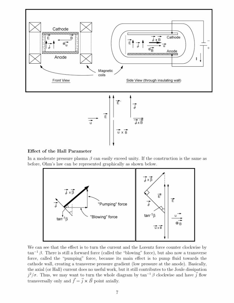
Effect of the Hall Parameter
In a moderate pressure plasma β can easily exceed unity. If the construction is the same asbefore, Ohm’s law can be represented graphically as shown below.
We can see that the effect is to turn the current and the Lorentz force counter clockwise bytan−1 β. There is still a forward force (called the “blowing” force), but also now a transverseforce, called the “pumping” force, because its main effect is to pump fluid towards thecathode wall, creating a transverse pressure gradient (low pressure at the anode). Basically,the axial (or Hall) current does no useful work, but it still contributes to the Joule dissipationj2/σ. Thus, we may want to turn the whole diagram by tan−1 β clockwise and have ~j flow
~transversally only and f = ~j � ~B point axially.
7
×
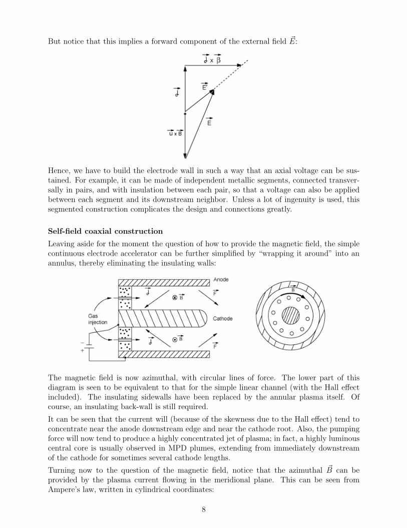
~But notice that this implies a forward component of the external field E:
Hence, we have to build the electrode wall in such a way that an axial voltage can be sus-tained. For example, it can be made of independent metallic segments, connected transver-sally in pairs, and with insulation between each pair, so that a voltage can also be appliedbetween each segment and its downstream neighbor. Unless a lot of ingenuity is used, thissegmented construction complicates the design and connections greatly.
Self-field coaxial construction
Leaving aside for the moment the question of how to provide the magnetic field, the simplecontinuous electrode accelerator can be further simplified by “wrapping it around” into anannulus, thereby eliminating the insulating walls:
The magnetic field is now azimuthal, with circular lines of force. The lower part of thisdiagram is seen to be equivalent to that for the simple linear channel (with the Hall effectincluded). The insulating sidewalls have been replaced by the annular plasma itself. Ofcourse, an insulating back-wall is still required.
It can be seen that the current will (because of the skewness due to the Hall effect) tend toconcentrate near the anode downstream edge and near the cathode root. Also, the pumpingforce will now tend to produce a highly concentrated jet of plasma; in fact, a highly luminouscentral core is usually observed in MPD plumes, extending from immediately downstreamof the cathode for sometimes several cathode lengths.
~Turning now to the question of the magnetic field, notice that the azimuthal B can beprovided by the plasma current flowing in the meridional plane. This can be seen fromAmpere’s law, written in cylindrical coordinates:
8

1µ0jr =
r
∂Bx ∂B
∂θ− θ
∂x= −∂Bθ
∂xfor Bx = 0 (19)
µ0jx =1
r
∂(rBθ)
∂r− 1
r
∂Br
∂θ=
1
r
∂(rBθ)for Br = 0 (20)
∂r
~The direction of B is also that required for acceleration. This can be seen either from theequations, or from the right hand rule applied to a number of representative ~j vectors, orfrom the known fact that parallel wires carrying current in the same direction attract eachother.
The magnitude of the magnetic field at a point P can be simply related to the amount ofcurrent I 0 which crosses the surface S. This surface leans on the ring that contains P andextends around the cathode tip as shown.
We have, from the integral form of Ampere’s law,
I 0B(P ) = µ0 (21)
2πr
where r is the radial coordinate of P . In particular, I 0 = I, the total current, for any pointon the insulating backplate, and I 0 is zero for points like Q, outside the cylinder.
Approximate calculation of thrust
There are two major contributions to the thrust of our coaxial accelerator. One of themis the familiar integral of the gas pressure over the back-facing surfaces. This is called the“electrothermal” or “aerodynamic”( ) thrust, and would be the only one acting in a device
~where j2/σ dominates over ~j �B �~u (or, for that matter, in a chemical rocket). The other
component is the reaction to the Lorentz forces exerted on the plasma, and is physicallyapplied as a magnetic force on some of the metallic conductors carrying current to thethruster. For example, looking at the figure, and assuming for simplicity that the conductorsin the back are arranged symmetrically, we see that at points like R the enclosed current forthe loop shown is the total current I, and so B = µ0I/2πr, in the same direction as insidethe engine. Across the radial wires, B goes to zero, but at least a part of each wire is subject
9
′
′
′
×
′

to B, and since its current is radially outwards, the Lorentz force on it is to the left, i.e., athrust.
At high efficiencies, the electromagnetic thrust dominates over the electrothermal thrust. Wecan calculate it relatively easily with a few assumptions. First, we have exactly (by actionand reaction),
1~F =
∫~j � ~
EM B dV = ~µ0
∫ (r�B
)� ~B dV (22)
In general,
( ) ( ) (B2
r� ~ ~ ~B �B = B � r ~B �r (23)2
)But since j ~Bj does not vary along its own direction in our case,
(~B � r
) B2~B = � ir
r
(no axial component, integrates to zero by symmetry).
1~FEM = �µ0
∫r(B2
dV2
)(24)
and by the vectorial version of Gauss’ theorem,
1~FEM = �µ0
∫B2
~dA (25)2
~where the integral extends to the surface surrounding the plasma and dA points outwardsfrom that surface. We are interested only on the axial force, so,
1FEM = �
µ0
∫B2
dAx (26)2
where now dAx is the projection of each area element normal to the axial direction. Inparticular, for any cylindrical surface, dAx = 0. The only surfaces surrounding the plasmawhich face backwards (or forward) are the backplate, the cathode tip and the anode rim.For the backplate, using (24) with I 0 = I, we calculate the contribution
F backplate1
EM = +µ0
∫ Ra
Rc
1
2
(µ0I
2πr
)2
2πrdr =µ0I
2
4πlnRa
(27)Rc
where Ra and Rc are the anode and cathode radii, and the (+) sign is because the normal~dA to the surface points backwards (i.e., out of the plasma).
The calculation of the cathode tip and anode rim contributions is much more involved,since we would need to know the distribution of current on these surfaces. However, forconventionally built thrusters, these contributions have been estimated to amount to at
10
× ∇× ×
∇× × · ∇ −∇
· ∇ −
− ∇
−
−
′
| |

most 10% of the total (most of the current flows from the cylindrical part of the anode tothe back of the cathode). Thus, if we also neglect the electrothermal thrust, the device thrustwould be a reasonable approximation to Eq. (27), F � F backplate
EM , also known as Maecker’slaw.
Notice:
� F is independent of size.
� F scales as the square of the total current.
These rules are observed to apply quite well in practice. For example, the enclosed figure,from experiments at Princeton, shows the quadratic dependence very clearly.
Using Eq. (27), the expression for the exit velocity (and hence the specific impulse) followseasily,
Fue =
m�(µ0
4πlnRa
Rc
)I2
(28)m
The speed of sound at representative points in the flow will scale like M−1 (M is the molecularmass of the gas), and from Eq. (28) we see that the Mach number (say, at exit) must varylike the quantity,
I2pM
≈
•
•
(29)m
This parameter has been found indeed to be the most important scaling parameter for MPDthrusters. In particular, it has been found that for each geometrical arrangement, a limiting
11
≈
√

value of I2pM/m exists beyond which the operation becomes highly unsteady and erosion
of the electrodes increases by orders of magnitude. The data for many values of I, m and
I2p
even for different propellants show this limit at about the same critical value
(M)�
ofm
the parameter. Representative values for Argon (M = 40 g/mole),
I� = 23,000 A and m� = 6 g/s
giving, (I2pM
m
)�= 560 (I in kA, M in g/mol, m in g/s)
˙
However, this limit can be modified by changes in the configuration of the engine, and muchresearch is being done to push it to as high values as possible. The reason is that as thisparameter increases,p so does the ratio of magnetic pressure B2/2µ0 � I2 to dynamic pressure� mu � m/p M , and hence, the relative importance of electromagnetic effects. Thus, highvalues of I2 M/m lead to high thruster efficiency, and (as shown by Eq. (28)) high specificimpulse.
The electrical characteristics of the accelerator can also be estimated. If the thrust efficiencyis,
mu2
η = e
2IV=
F 2
2mIV
then, using Eq. (28) we obtain,
1V =
2η
(µ0
4πlnRa
Rc
)2I3
(30)m
12
√
√ ∗
√ ∗
∼∼ ∼
√√
∗ ∗
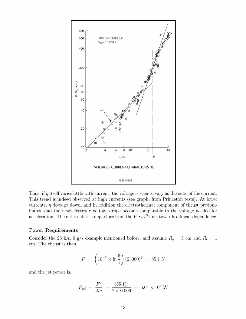
Thus, if η itself varies little with current, the voltage is seen to vary as the cube of the current.This trend is indeed observed at high currents (see graph, from Princeton tests). At lowercurrents, η does go down, and in addition the electrothermal component of thrust predom-inates, and the near-electrode voltage drops become comparable to the voltage needed foracceleration. The net result is a departure from the V � I3 line, towards a linear dependence.
Power Requirements
Consider the 23 kA, 6 g/s example mentioned before, and assume Ra = 5 cm and Rc = 1cm. The thrust is then,
F =
(10−7 5� ln
)(23000)2 = 85.1 N
1
and the jet power is,
F 2
Pjet =2m
=(85.1)2
= 6.042� 0.006
� 105 W
13
∼
×
××
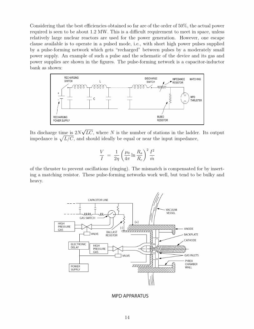
Considering that the best efficiencies obtained so far are of the order of 50%, the actual powerrequired is seen to be about 1.2 MW. This is a difficult requirement to meet in space, unlessrelatively large nuclear reactors are used for the power generation. However, one escapeclause available is to operate in a pulsed mode, i.e., with short high power pulses suppliedby a pulse-forming network which gets “recharged” between pulses by a moderately smallpower supply. An example of such a pulse and the schematic of the device and its gas andpower supplies are shown in the figures. The pulse-forming network is a capacitor-inductorbank as shown:
Its discharge time is 2Np
imp√ LC, where N is the number of stations in the ladder. Its output
edance is L/C, and should ideally be equal or near the input impedance,
V
I=
1
2η
(µ0
4πlnRa
Rc
)2I2
m
of the thruster to prevent oscillations (ringing). The mismatch is compensated for by insert-ing a matching resistor. These pulse-forming networks work well, but tend to be bulky andheavy.
14
√

MIT OpenCourseWarehttp://ocw.mit.edu
16.522 Space PropulsionSpring 2015
For information about citing these materials or our Terms of Use, visit: http://ocw.mit.edu/terms.