setting up digital mode software on the flex 6000 series...
TRANSCRIPT

1
Setting Up Digital Mode Software on the Flex-6000 Series Radios
Doug Reece
AK4AO
Version 1.0
March 29, 2016
2
Contents 1.0 About this document .............................................................................................................................. 3
2.0 AK4AO Hardware and Software Environment ........................................................................................ 3
2.1 Current ................................................................................................................................................ 3
2.2 Installed for evaluation ....................................................................................................................... 3
2.3 Planned for the future ........................................................................................................................ 3
3.0 Setting up digital mode applications on the Flex .................................................................................... 4
3.1 Common setup steps for any/all of WSJT-X, Fldigi, MMTTY, and N1MM+ ........................................ 4
3.2 WSJT-X Installation .............................................................................................................................. 5
3.3 JT Alert Installation ........................................................................................................................... 12
3.4 Fldigi Installation ............................................................................................................................... 13
3.5 MMTTY Setup .................................................................................................................................... 18
3.6 N1MM+ Setup ................................................................................................................................... 23
3.7 CWGet (CW decoding software) – Future topic ............................................................................... 24
3.8 Free DV (Digital Voice software) – Future topic ............................................................................... 24
4.0 Skimmer setup ...................................................................................................................................... 25
5.0 Resources .............................................................................................................................................. 26
5.2 Skimmer Software Web Sites ............................................................................................................ 26
5.3 Other Mentioned Software Web Site ............................................................................................... 26

3
1.0 About this document This document is not intended to be a substitute for the often-extensive documentation provided for
the products discussed. However, the Flex-6000 radios provide unique opportunities for using the
packages, such as the ability to run multiple instances on different bands and/or to run multiple
products on the same band simultaneously. The procedures for doing these things are not always easy
fully explained or easy to locate in product documentation, and I have attempted to bring this Flex-
specific information together in this document.
The document reflects the hardware/software environment at my station and my current operating
preferences and capabilities. I hope to update it as I learn more, and perhaps other authors will join in
future versions of the document.
2.0 AK4AO Hardware and Software Environment
2.1 Current Hardware: Flex-6500 transceiver with the latest version of SmartSDR as of the document date
Logging software: DXKeeper, part of the DXLab suite of applications. (No special instructions needed
for Flex-6000)
Digital Mode Software:
WSJT-X for JT65/JT9 modes
JT-Alert – Adds information to WSJT-X display and integrates with DXKeeper
Fldigi – Supports many digital modes, including RTTY, PSK31/63, and Olivia
MMTTY – for RTTY, especially contesting
N1MM+ contest operations and logging
2.2 Installed for evaluation RTTY Skimmer – monitor RTTY signals on multiple bands and provide spotting information
SDR-Bridge – allows RTTY Skimmer and CW Skimmer to work with Flex 6000
2.3 Planned for the future CWGet – machine decoding of CW signals
CWSkimmer – monitor CW signals on multiple bands and provide spotting information
FreeDV wave form and application – Voice over digital mode
4
3.0 Setting up digital mode applications on the Flex This section of the document covers the specifics of setup on the Flex 6000 series radios of selected
software products designed to decode digital mode signals and allow QSOs to be conducted.
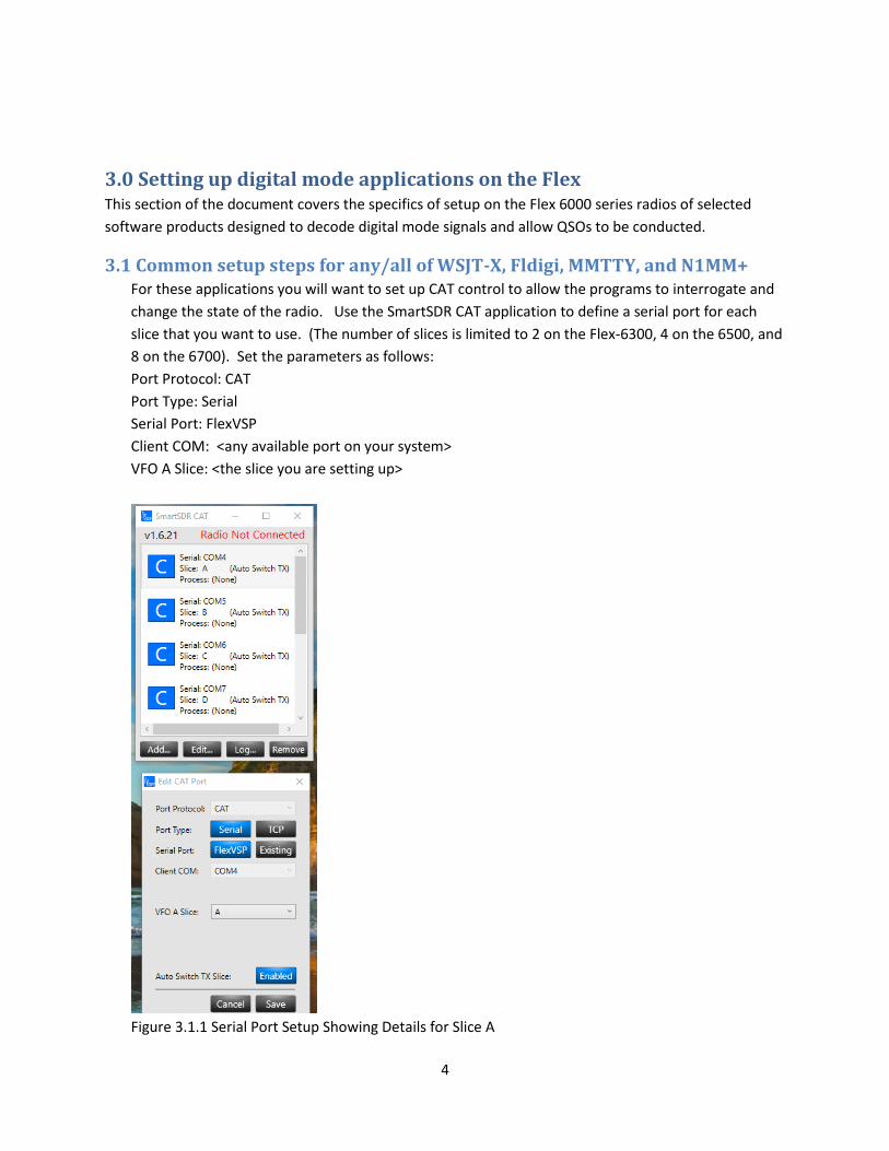
3.1 Common setup steps for any/all of WSJT-X, Fldigi, MMTTY, and N1MM+ For these applications you will want to set up CAT control to allow the programs to interrogate and
change the state of the radio. Use the SmartSDR CAT application to define a serial port for each
slice that you want to use. (The number of slices is limited to 2 on the Flex-6300, 4 on the 6500, and
8 on the 6700). Set the parameters as follows:
Port Protocol: CAT
Port Type: Serial
Serial Port: FlexVSP
Client COM: <any available port on your system>
VFO A Slice: <the slice you are setting up>
Figure 3.1.1 Serial Port Setup Showing Details for Slice A

5
Applications other than JT-Alert will need to be set up once for each slice to be used. It is essential
that the Slice, Audio Device, and COM Port configured for each slice be consistent. I recommend
that you always use DAX Channel 1 for slice A, DAX Channel 2 for slice B, etc. After you have set up
your COM ports, I would suggest you make a table of the settings needed for each slice. See below
for mine.
Slice COM Port DAX Channel Audio Receive Device
Audio Transmit Device
A 4 1 DAX Audio RX1 DAX Audio TX
B 5 2 DAX Audio RX2
C 6 3 DAX Audio RX3
D 7 4 DAX Audio RX4
Figure 3.1.2. Example of Application Setup Parameters. COM ports will vary depending on
availability on your system.
3.2 WSJT-X Installation Note: Before installing WSJT-X you will need to set up appropriate software to synchronize your
computer’s clock with a source of standard time. Since JT65/JT9 users transmit on alternate
minutes, it is necessary for both parties to a contact to agree closely on the start time for each
minute. You can find recommendations and directions in section 3.1 of the WSJT-X
documentation.
You need only install WSJT-X once regardless of the number of copies you will use
simultaneously. However, you will need to have a configuration file for each slice. After you
have done a standard installation of WSJT-X, you will need to make a copy of the program icon
for each slice you will use. You could start by renaming the icon from the standard installation
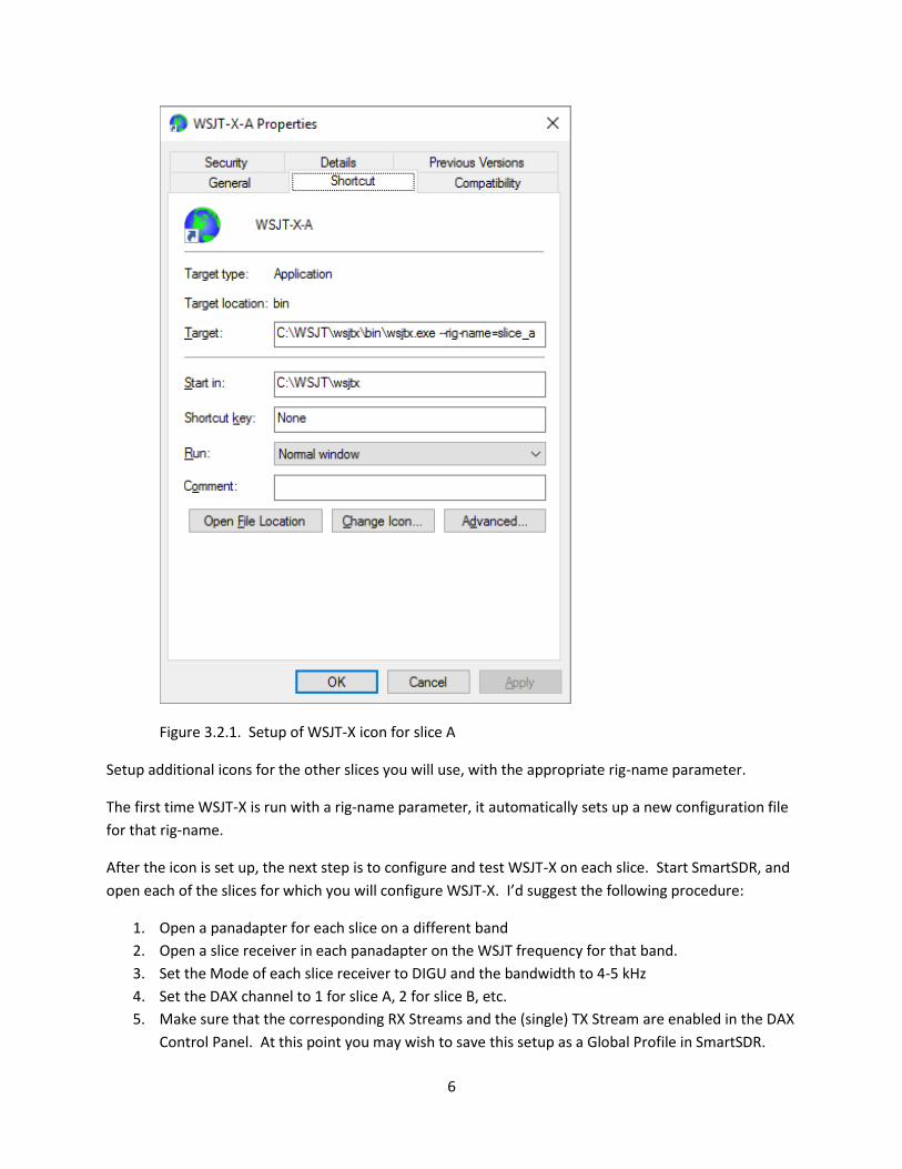
to use it for slice A as follows: First, right click the icon and select Properties. On the general tab
of the properties window, give the icon a new name. I use WSJT-X-A for Slice A, etc. Then, go to
the Shortcut tab and add a unique rig-name parameter to the Target specification, per the
illustration below.
6
Figure 3.2.1. Setup of WSJT-X icon for slice A
Setup additional icons for the other slices you will use, with the appropriate rig-name parameter.
The first time WSJT-X is run with a rig-name parameter, it automatically sets up a new configuration file
for that rig-name.
After the icon is set up, the next step is to configure and test WSJT-X on each slice. Start SmartSDR, and
open each of the slices for which you will configure WSJT-X. I’d suggest the following procedure:
1. Open a panadapter for each slice on a different band
2. Open a slice receiver in each panadapter on the WSJT frequency for that band.
3. Set the Mode of each slice receiver to DIGU and the bandwidth to 4-5 kHz
4. Set the DAX channel to 1 for slice A, 2 for slice B, etc.
5. Make sure that the corresponding RX Streams and the (single) TX Stream are enabled in the DAX
Control Panel. At this point you may wish to save this setup as a Global Profile in SmartSDR.
7
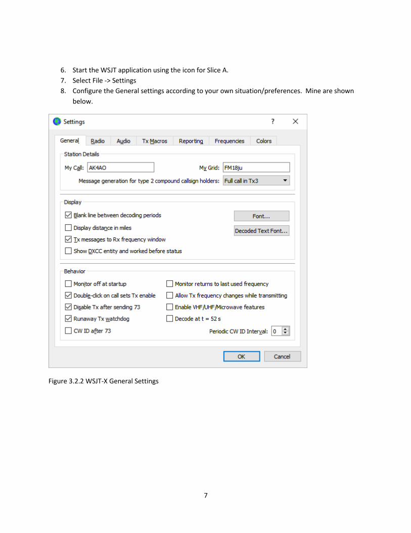
6. Start the WSJT application using the icon for Slice A.
7. Select File -> Settings
8. Configure the General settings according to your own situation/preferences. Mine are shown
below.
Figure 3.2.2 WSJT-X General Settings
8
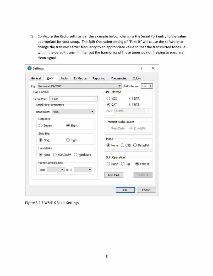
9. Configure the Radio settings per the example below, changing the Serial Port entry to the value
appropriate for your setup. The Split Operation setting of “Fake It” will cause the software to
change the transmit carrier frequency to an appropriate value so that the transmitted tones lie
within the default transmit filter but the harmonics of those tones do not, helping to ensure a
clean signal.
Figure 3.2.3 WSJT-X Radio Settings

9
10. Configure the Audio settings per the example below, selecting the Input audio value appropriate
to the slice you are setting up.
Figure 3.2.4 WSJT-X Audio Settings
10
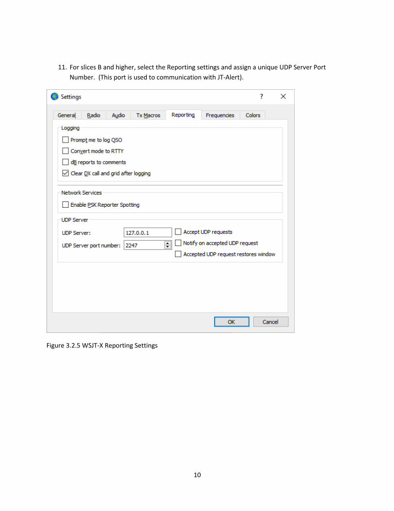
11. For slices B and higher, select the Reporting settings and assign a unique UDP Server Port
Number. (This port is used to communication with JT-Alert).
Figure 3.2.5 WSJT-X Reporting Settings
11
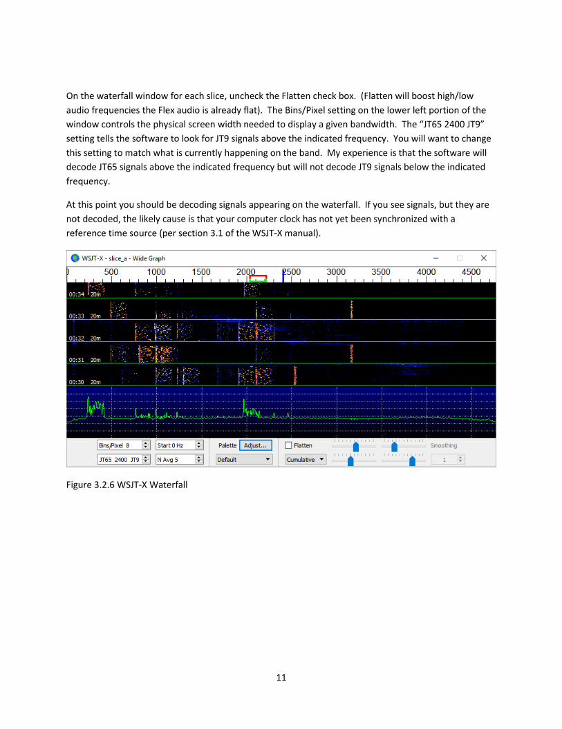
On the waterfall window for each slice, uncheck the Flatten check box. (Flatten will boost high/low
audio frequencies the Flex audio is already flat). The Bins/Pixel setting on the lower left portion of the
window controls the physical screen width needed to display a given bandwidth. The “JT65 2400 JT9”
setting tells the software to look for JT9 signals above the indicated frequency. You will want to change
this setting to match what is currently happening on the band. My experience is that the software will
decode JT65 signals above the indicated frequency but will not decode JT9 signals below the indicated
frequency.
At this point you should be decoding signals appearing on the waterfall. If you see signals, but they are
not decoded, the likely cause is that your computer clock has not yet been synchronized with a
reference time source (per section 3.1 of the WSJT-X manual).
Figure 3.2.6 WSJT-X Waterfall

12
3.3 JT Alert Installation JT Alert reports the geographic location (DXCC Entity, state/province) corresponding to each call
sign decoded and color codes the display to let you know which call signs represented wanted
states, DXCC entities, etc., according to the configuration you have selected. Further
information and setup instructions for JT Alert can be found on the http://www.hamapps.com
web site and will not be repeated here. You only need to install a single copy of JT Alert to run
multiple instances, but there are a few things you need to know:
- JT Alert does not automatically track changes to the contents of your log. You must
periodically go to the Settings option and the menu and select Scan Log. You should do this
function and any other program updates with only a single copy of JT Alert running. All JT
Alert instances will use the same copy of the resulting configuration files and the worked-
before information,
- To run multiple copies of JT Alert, start the desired number of copies of WSJT-X, and then
start JT Alert the same number of times. It will automatically connect the first copy of JT
Alert to the first copy of WSJT-X that was started, etc. Allow a few seconds between each
start so that the JT Alert has time to make the connection; otherwise, you may get two
copies of JT Alert connected to the same WSJT-X window. Also, make sure that each WSJT-X
instance is configured with a unique UDP port per instructions above.
- I sometimes want to stop an instance of WSJT-X/JT Alert in order to run other software,
such as Fldigi, to explore signals for modes other than JT65/JT9. I’ve found that the easiest
way to switch in and out of WSJT-X/JT Alert is as follows:
o I start WSJT for the various slices in order: A, B, C, D
o I then start JT Alert in the same order
o If I want to turn off a WSJT instance, I do so on slice D. Then, I can restart WSJT-X/JT
Alert on slice D if desired without JT Alert becoming confused about which WSJT-X
window it should connect to.
13
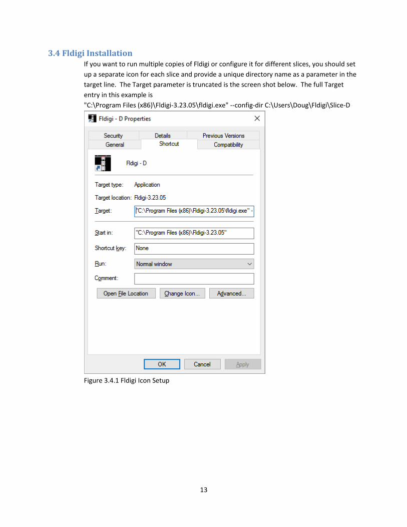
3.4 Fldigi Installation If you want to run multiple copies of Fldigi or configure it for different slices, you should set
up a separate icon for each slice and provide a unique directory name as a parameter in the
target line. The Target parameter is truncated is the screen shot below. The full Target
entry in this example is
"C:\Program Files (x86)\Fldigi-3.23.05\fldigi.exe" --config-dir C:\Users\Doug\Fldigi\Slice-D
Figure 3.4.1 Fldigi Icon Setup

14
For each slice you want to set up, you should download the corresponding rig description
file from https://sourceforge.net/projects/fldigi/files/xmls/flex/
The rig control files are XML documents that contain the appropriate setup parameters for
Flex 6000 radios. I prefer to place these XML files in the corresponding config-dir directory
for each slice.
When Fldigi is first run with each icon you set up, it will take you through a set of configuration screens.
The Operator screen entries are straightforward.
Figure 3.4.2 Fldigi Operator Parameters Example
15
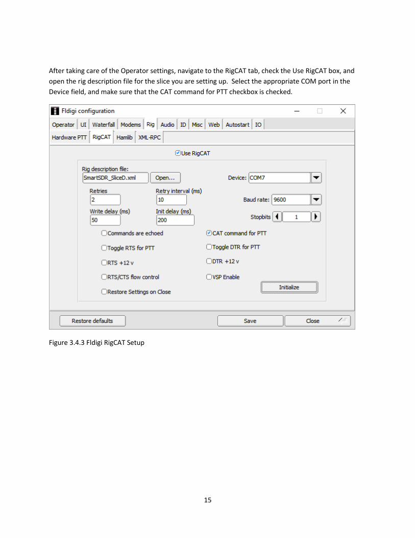
After taking care of the Operator settings, navigate to the RigCAT tab, check the Use RigCAT box, and
open the rig description file for the slice you are setting up. Select the appropriate COM port in the
Device field, and make sure that the CAT command for PTT checkbox is checked.
Figure 3.4.3 Fldigi RigCAT Setup
16
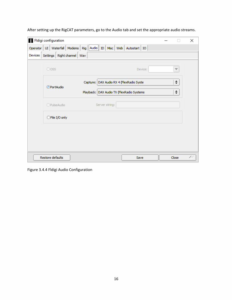
After setting up the RigCAT parameters, go to the Audio tab and set the appropriate audio streams.
Figure 3.4.4 Fldigi Audio Configuration

17
Each copy of Fldigi you set up will have its own set of configuration files, which include the log and
macro files. I manually export the needed entries from the appropriate Fldigi log and import to my
DXKeeper log.
Note also that at least some of the macros provided automatically by Fldigi will need to be customized
per instructions in the Fldigi documentation. Once satisfied with your macros, you will probably want to
copy them to all instances.
18
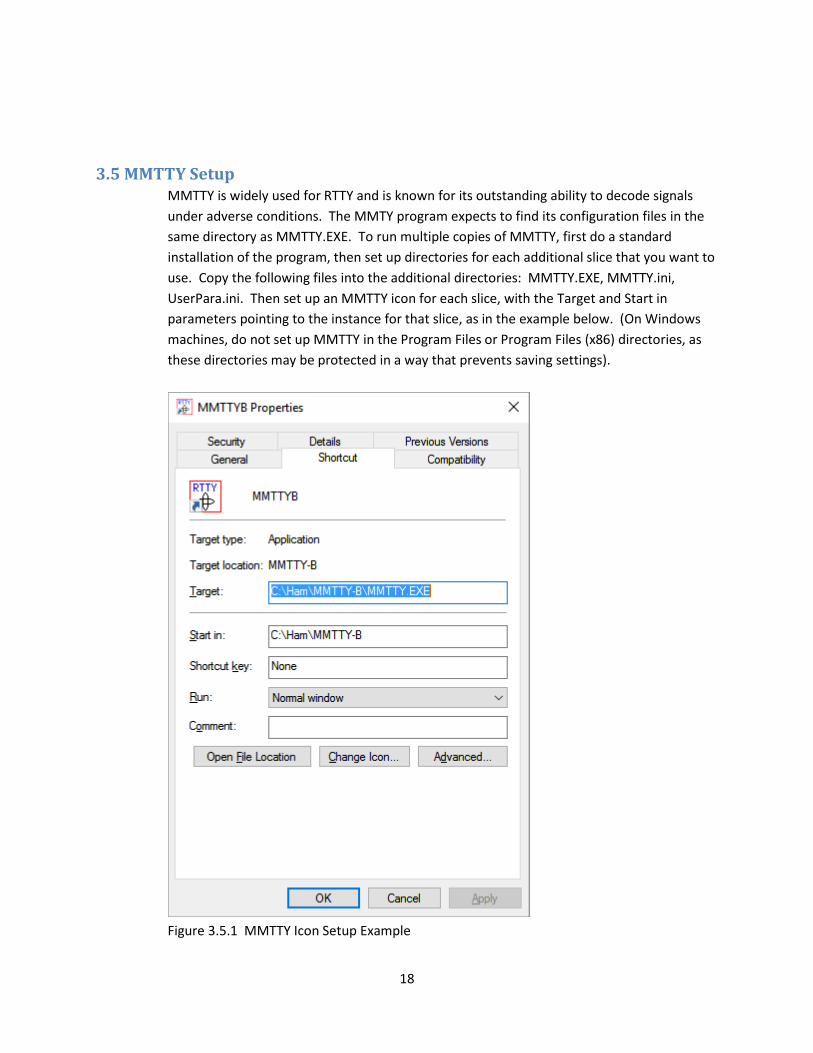
3.5 MMTTY Setup MMTTY is widely used for RTTY and is known for its outstanding ability to decode signals
under adverse conditions. The MMTY program expects to find its configuration files in the
same directory as MMTTY.EXE. To run multiple copies of MMTTY, first do a standard
installation of the program, then set up directories for each additional slice that you want to
use. Copy the following files into the additional directories: MMTTY.EXE, MMTTY.ini,
UserPara.ini. Then set up an MMTTY icon for each slice, with the Target and Start in
parameters pointing to the instance for that slice, as in the example below. (On Windows
machines, do not set up MMTTY in the Program Files or Program Files (x86) directories, as
these directories may be protected in a way that prevents saving settings).
Figure 3.5.1 MMTTY Icon Setup Example

19
To configure and test MMTTY, start SmarSDR and open a slice receiver for the target slice in either RTTY
or DIGL mode. As usual the DAX Channel must be set appropriately for the slice and be enabled in the
DAX control panel. Open MMTTY, select Option (O) -> Setup MMTTY…. Select the TX tab, enter your
call sign, and make sure that the PTT & FSK Port setting is set to None. See below.
Figure 3.5.2 MMTTY TX Setup

20
Next, press the Radio Command button, select the appropriate CAT port for the slice you are setting up,
and set the other parameters on the Radio Command screen as shown below.
Figure 3.5.3 MMTTY Radio Command parameters

21
Go to the SoundCard tab, select the appropriate Reception stream and the Transmit stream.
Figure 3.5.3 MMTTY SoundCard Settings
22
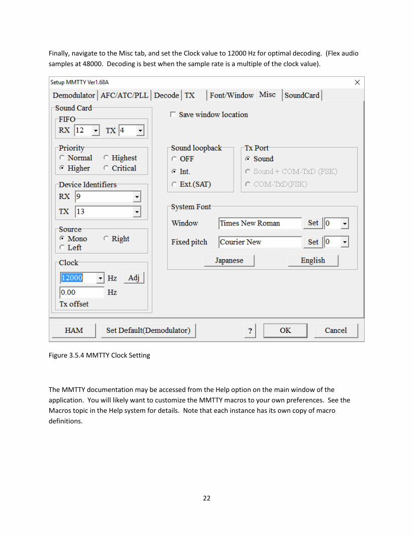
Finally, navigate to the Misc tab, and set the Clock value to 12000 Hz for optimal decoding. (Flex audio
samples at 48000. Decoding is best when the sample rate is a multiple of the clock value).
Figure 3.5.4 MMTTY Clock Setting
The MMTTY documentation may be accessed from the Help option on the main window of the
application. You will likely want to customize the MMTTY macros to your own preferences. See the
Macros topic in the Help system for details. Note that each instance has its own copy of macro
definitions.

23
3.6 N1MM+ Setup N1MM+ can support operations on a single band, or you can operate on two bands at once
using a SO2R (Single Operator 2 Radios) configuration. Flex Radio is considering how
N1MM+ SO2V (Single Operator 2 VFOs) might be supported in a future release.
The MMTTY and/or Fldigi engines can be used from within N1MM+, and instructions for
doing so are provided in the N1MM+ documentation.
I have N1MM+ set up to key the rig using a PTT port configured as shown below:
Figure 3.6.1 PTT Port Configuration for N1MM+
If you want to use MMTTY and/or Fldigi within N1MM+, set up separate instances per the
N1MM+ documentation.

24
3.7 CWGet (CW decoding software) – Future topic
3.8 Free DV (Digital Voice software) – Future topic
25
4.0 Skimmer setup You can use skimmer software to monitor RTTY or CW signals on multiple bands using the wide band
(up to 96 kHZ) Flex IQ feeds. See the Resources page for information on CW Skimmer and RTTY
Skimmer software. These software products attempt to decode all signals (or signals as defined in
the configuration file, e.g., calling CQ) within the appropriate sub-band in the number of bands
supported on your Flex radio (2 on the 6300, 4 on the 6500, 7 on the 6700). Successfully decoded
signals are presented with the same Telnet interface as a DX spotting site. The results can be
viewed on a Telnet terminal program or via software such as Spot Collector within the DXLab Suite.
(Spot Collector can be configured to interact with your DXKeeper log and report only needed call
signs).
To use either skimmer, you must do the following:
- Install and configure the software per instructions in their respective documentation.
- Install SDR Bridge (See Resources section)
- Start SmartSDR, and open panadapters on the bands of interest
- Enable the IQ feeds in each panadapter
- Set the IQ steam Sample Rate to 96000 in the DAX Control Panel, but do NOT enable the
streams (as SDR Bridge bypasses the DAX Control Panel)
26
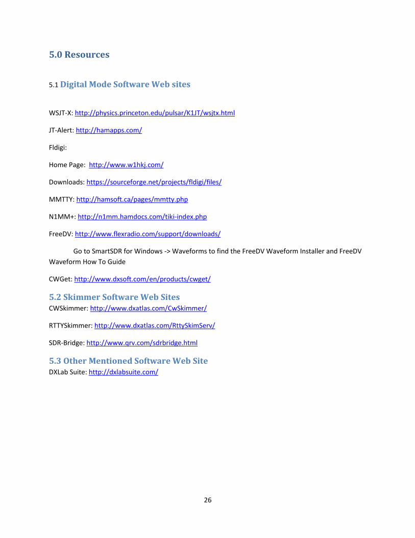
5.0 Resources
5.1 Digital Mode Software Web sites
WSJT-X: http://physics.princeton.edu/pulsar/K1JT/wsjtx.html
JT-Alert: http://hamapps.com/
Fldigi:
Home Page: http://www.w1hkj.com/
Downloads: https://sourceforge.net/projects/fldigi/files/
MMTTY: http://hamsoft.ca/pages/mmtty.php
N1MM+: http://n1mm.hamdocs.com/tiki-index.php
FreeDV: http://www.flexradio.com/support/downloads/
Go to SmartSDR for Windows -> Waveforms to find the FreeDV Waveform Installer and FreeDV
Waveform How To Guide
CWGet: http://www.dxsoft.com/en/products/cwget/
5.2 Skimmer Software Web Sites CWSkimmer: http://www.dxatlas.com/CwSkimmer/
RTTYSkimmer: http://www.dxatlas.com/RttySkimServ/
SDR-Bridge: http://www.qrv.com/sdrbridge.html
5.3 Other Mentioned Software Web Site DXLab Suite: http://dxlabsuite.com/