settling basin design and performance - welcome to the national
TRANSCRIPT

71
Settling Basin Design and Performance
Daniel StecheyCanadian Aquaculture Systems
1076 Tillison AvenueCoboarg, Ontario K9A 5N4
CANADA
Abstract not available at time of printing.

72
Constructed Wetlands for Water Treatment in Aquaculture
Michael J. MassingillVice President of Production
Elisabeth M. Kasckow Rodney J. Chamberlain Water Quality Manager Facility Manager
James M. Carlberg Jon C. Van Olst President Director of Research
Kent Seafarms Corporation11125 Flintkote Avenue, Suite J, San Diego, CA 92121
Introduction
Wetlands
Natural wetlands have long been regarded as important ecosystems that provide habitatfor many types of aquatic and riparian plants and animals. In addition, natural wetlandsplay an important role in restoring the quality of the water that passes through them byreducing suspended solids, removing nitrogen and phosphorous nutrients, and trapping orconverting other natural or man-made pollutants (Hammer, 1997; Kadlec & Knight,1996).
Considerable interest has developed in trying to understand the mechanisms at workwithin natural wetlands, and to model and incorporate their positive water treatmentfeatures into artificial or “constructed” wetlands (Moshiri 1993; Hammer 1991; Reed,Middlebrooks, & Crites, 1988). Within the last decade, numerous constructed wetlandshave been built to replace the loss of natural wetlands, to provide additional plant andanimal habitat, to provide new aesthetic and recreational environments for people, and foruse as water treatment systems for several types of municipal, industrial, and agriculturalwastewater.
Constructed Wetlands for Water Treatment
As water resources become increasingly scarce, and standards for the quality ofwastewater effluents become more stringent, the traditional approach for wastewatertreatment is becoming more expensive. Constructed wetlands are often selected as a lesscostly alternative to the more typical wastewater treatment plant. In some applications,this technology may be employed for less than 1/10th the cost of conventional sewagetreatment systems. It often involves lower construction costs, lower maintenance costs,simpler designs, and lower pumping heads (Olson 1993).

73
Types of Constructed Wetlands
Constructed wetlands have been classified into two general types; free water surfacewetlands (FWS) or subsurface wetlands (SF). Free water surface wetlands have theirwater surfaces exposed to the atmosphere while subsurface wetlands have their waterssubmerged within a layer of rock, gravel or other water permeable media with no watervisible above ground (Reddy and Smith 1987, Reed 1990). FSW wetlands are usually lessexpensive to construct and operate, while SF wetlands may require less land, and canreduce public contact to the water within the system (U.S. EPA, 1992).
Kent Seafarms Constructed Wetlands
Kent Seafarms has operated a large-scale intensive hybrid striped bass production facilityin the southern California desert since 1984. This operation near Palm Springs currentlyproduces over 1.3 million kg of hybrid striped bass annually. These fish are raised in 96circular concrete tanks at an average density of 50 kg/m3, utilizing a limited supply of26°C well water.
Several years ago, we began a research effort to recirculate a portion of our water througha series of open-water ponds. The objective of this effort was to evaluate whether afraction of the water flow could be nitrified and reused for additional production withinour intensive striped bass rearing system. We utilized 14 fingerling production ponds of0.6 hectare x 1 m depth each that were no longer needed for fish production purposes.These open-water ponds were connected in series and supplied with untreated andunsettled farm effluent having an average of 3-5 mg/l of total ammonia nitrogen (TAN).With little maintenance effort required, the ponds were shown to be capable of reducingTAN to 0.25 -1.0 mg/l, at input flows of up to 4,500 liters/minute (1,200 gpm) ofuntreated water. Although summer treatment was certainly a function of strong algalproductivity, continued ammonia reduction through the winter months (when algaldensities were very low) suggested that significant nitrification activity was occurring.
Based upon these results, we believed it would be useful to undertake a program todevelop FWS constructed wetlands, particularly if the added bacterial substrate of suchwetlands could optimize nitrification without stimulating algal blooms common to open-water ponds.
Methods and Results
Beginning in 1995, Kent Seafarms, with funding provided by the Department ofCommerce’s Advanced Technology Program, designed and constructed an experimentalaquaculture wastewater treatment system consisting of three separate components. Itconsists of a biological particulate removal system, a bacterial nitrification reactor, and aconstructed FWS bulrush wetland for final nutrient and solids removal. This system is

74
being evaluated for its potential to treat and recirculate water leaving our striped basstanks, as well as providing treated water to other agricultural and recreational users.
The design treatment goal for the recirculating striped bass production system is tomaintain maximum ammonia concentrations at less than 3.5 mg/l. Water inputs consist ofapproximately 11,000 l/min of well water combined with an anticipated “treated”recirculated flow of 38,000 l/min (total flow of 49,000 l/min). This water is expected tosupport a standing crop of 400,000 kg of hybrid striped bass at a total daily feed level of5,700 kg of feed.
The final treatment component of this system is a constructed FWS bulrush wetland. Itspurpose is to act as a suspended solids clarifier and polishing nitrification reactor prior torecycling “treated” water back to the striped bass production system. The remainder ofthis paper discusses preliminary results of our experiments with this constructed wetlandcomponent.
Constructed Wetland Design
We constructed 28 parallel earthen FWS wetland study ponds, each approximately 274 mX 9 m (16 ponds) and 212 m X 9 m (12 ponds). Each pond has a surface area of 2,508m2 or 1,895 m2, respectively. All ponds were designed with an average water depth of 46cm (18”), except ponds 27 & 28 which were deepened to 92 cm (36”) to study possibleeffects of water depth. Each pond was supplied in parallel with up to 1600 l/min ofstriped bass effluent water, via gravity flow from our striped bass production tanksthrough a centrally located water distribution canal.
To establish the bulrush communities in our ponds, we followed the practicesrecommended by Allen et al. (1991) and planted the excavated earthen ponds with twonative southern California species of bulrush, Scirpus californicus, and Scirpus acutus.These plants were selected for their demonstrated hardiness in our desert climate,tolerance to high ammonia and solids loading, availability, and successful utilization fornitrification in other constructed wetlands (Gersberg et al. 1986; Surrency 1993).
The following experiments were designed to study the primary effects of hydraulicretention time, water depth, and supplemental aeration on nitrification (Ammonia-->Nitrite---> Nitrate) in bulrush FWS wetlands:
Experiment 1 - Effects of Hydraulic Retention Time on Ammonia Removal
Nine of the 274 m long experimental wetlands, fully vegetated with bulrush, Scirpuscalifornicus, were used in this study. Three replicates of three different water inflow rateswere established to compare the effects of different hydraulic retention times (HRT) onammonia removal as well as other water quality constituents. This experiment wasconducted in 3 separate trials:
1) in the fall of 1996, with HRT’s of 1.1, 3.5 and 7.7 days,

75
2) in the winter of 1996, with HRT’s of 1.4, 6.9, and 12.8 days, and3) in the spring of 1997, with much shorter HRT’s of 0.6, 1.1, and 2.1 days.
Water quality parameters of influent and effluent water were measured by Kent Seafarmspersonnel twice weekly for all nine ponds. They included water flow rates, totalammonia-N (TAN), nitrite-N, nitrate-N, total nitrogen, pH, alkalinity, carbon dioxide,CBOD, dissolved oxygen, TSS, VSS, and temperature (APHA/AWWA/WEF, 1995).Data was analyzed with two-level nested ANOVA with equal sample size (Sokal, R.R.and F. J. Rohlf. 1981).
f f
e d b
a a c f
0
100
200
300
400
1.1 3.5 7.7 1.4 6.9 12.8 0.6 1.1 2.1 Hydraulic Retention Time (days)
Trial 1 July- October
1996
Trial 2 October-December
1996
Trial 3, Feb-Apr 1997
(*different letters within a trial are significantly different from each other at p<0.01) Fig. 1. Mass Ammonia Removal as a Function of HRT
As shown in Figure 1, we observed significantly differing outcomes with respect toammonia removal. The optimal hydraulic retention time (HRT) for the unaerated wetlandponds appeared to be no greater than 3.5 days, although no significant improvements werefound with shorter HRT’s.
The 0.6 to 3.5-day HRT ponds were able to remove between 237 to 433 mg NH3/m2/day,depending upon season, whereas the best removal rate of the longer retention times wasonly 106 mg NH3/m2/day for any season. However, in some cases, ponds with a 0.6-dayretention time actually showed some net ammonia production. Because additionalammonia is generated during decomposition of organic material within the ponds(ammoni-fication), we suspect that these results were due to the breakdown of volatilesuspended solids produced by the fish, which were efficiently settled out in the wetlandponds. We believe that a disproportionate share of solids were captured in the high flowponds due to a relatively constant effluent VSS, irrespective of water flow.
Experiment 2 - Water Depth effects on Ammonia Removal Rates
Wetland treatment processes are usually thought to be functions of wetland area ratherthan wetland volume (Kadlec & Knight 1996). However, our aquaculture application ofconstructed wetlands is primarily used for nitrification of high water volumes (40,000l/min) containing low effluent concentrations of ammonia, TSS, and BOD (<5 mg/l,<25mg/l, <30 mg/l, respectively). Such high flows and low concentrations are typical ofmany aquaculture effluents, but are unlike most other municipal or agricultural

76
wastewaters which are often very high in BOD, ammonia, and organic solids. We wereinterested in determining whether greater wetland depths could be cost-effective,particularly for recirculated aquaculture applications where nitrification is often moreimportant than total nitrogen control.
Two of the wetland ponds were excavated twice as deep as the other experimental ponds.When these were planted with bulrush transplants, the water depth was lowered to the 46cm (18”) typical of the other experimental ponds, allowing the bulrush to become wellestablished. Once the plants had established, the depth was increased to about 92 cm(36”) inches.
After allowing a full summer of growth for the bulrush to fully vegetate, studies wereconducted in these ponds from January of 1997 to the present. Samples of effluent fromeach wetland were measured twice each week for temperature, dissolved oxygen, pH, andammonia. Weekly measurements were taken for alkalinity, total nitrogen, nitrate, nitrite,and VSS. These measurements were compared to those taken in the shallow ponds, withwater flow set at either the same flowrate (half the hydraulic retention time) or at half theflowrate (equal hydraulic retention time).
Since we expected possible seasonal differences, we conducted several trials. The firsttrial was defined as spring for January to March 1997. The second trial was defined asearly summer for May to June 1997. During the latter part of this study, we installedsupplemental aeration in all the ponds, a decision based upon early results of Experiment1. Therefore, in trial 3, we compared depth effects under late summer aerated conditions(Aug. - Sept. 1997).
As seen in Figure 2, average ammonia removal rates of the two deeper ponds was as goodor better than the shallow ponds in each trial. During the spring (without aeration), thedeep ponds showed an average ammonia treatment rate of 292 mg/m2/day, whereasnormal depth ponds at the same HRT of 1.7-days exhibited treatment of 200 mg/m2/day.During the early summer, we decreased the HRT of the deep ponds slightly to about 1-day, and observed an average treatment rate of 247 mg/m2/day in the deep ponds, butobserved negative treatment of -13 mg/m2/day in the shallow ponds at the same flow rate(1/2 the HRT of deep ponds). We suspect the shallow ponds became oxygen limited athigh water flow rates. During the warm summer, effluent dissolved oxygen levelsaveraged less that 1.5 mg/l.
After supplemental aeration was added, average effluent dissolved oxygen levels increasedto 3 mg/l or greater , and we observed improved treatment of ammonia in all ponds. Theammonia removal rates were increased most in the deeper ponds (an average ammoniaremoval rate of 737 mg/m2/day), as compared to 537 mg/m2/day for shallow pondsoperated at the same HRT (1/2 the flow rate), and 473 mg/m2/day for ponds operated atthe same flow rate (1/2 the HRT). With and without aeration, the deep ponds performedsignificantly better in almost every trial.

77
-100
0
100
200
300
400
500
600
700
800
Spring, non-aerated Summer, non-aerated Summer, aerated
Deep (1.0m) ponds
Shallow (0.5 m) ponds @ same HRT, 1/2 flow
Shallow (0.5 m) ponds @ same flow, 2X HRT
Figure 2. Effects of Water Depth on Ammonia Removal
-13
Experiment 3 - The Effects of Aeration on Mass Ammonia Removal Rates
Since nitrification was a primary goal for our application of constructed wetlands, werealized that oxygen could become a limiting factor. Wetland plants have been shown tobe capable of delivering oxygen from the atmosphere to the plants’ root structure where itcan be utilized by aerobic bacteria (Gersberg, 1986). However, the process is rate limitedand controversy still exists as to whether such oxygen transport by plants is significant tothe wetland’s treatment capacity (Kadlec & Knight 1996). For our application, webelieved we would have an oxygen shortfall if high hydraulic loading was to be achieved.Approximately 4.6 g of oxygen are required for nitrification of 1g of ammonia to nitrate(E.P.A., 1990). Since the effluent from our fish production tanks often reaches 3-4 mg/lof ammonia, we could expect an oxygen demand of at least 14 -18 mg/l of oxygen fornitrification alone, not including any other biological or chemical oxygen demand.
This experiment was developed to determine the effectiveness of supplemental aeration foreconomical enhancement of ammonia removal in constructed wetlands. Based upon theearly results of Experiment 1, we were interested in whether aeration could significantlyreduce the hydraulic retention time necessary for maximizing mass ammonia removal.
For this study, we excavated bulrush and soil to a depth of about 2 m below water level inequally spaced strips across each of four previously vegetated wetland ponds (six cut-outsper pond). In each cut-out, we placed a PVC pipe with three equally spaced air diffusersset about 2-3’ below the water surface. All four ponds were aerated with a singleregenerative blower delivering 2-3 cfm of air per diffuser. Twice weekly measurementswere taken of the pond effluent for temperature, dissolved oxygen, pH, and ammonia.
Initial studies started in February of 1997 and compared aerated versus non-aerated pondsat two different HRT’s. We repeated these same studies in early summer, April to May1997, and late summer Aug. to Sept. 1997.

78
0 1 2 3 4 5 6 7
Non-Aerated
Aerated
DO Inflow
DO OutflowFigure 3a.
0
0.5
1
1.5
2
Non-Aerated
Aerated
TAN InflowTAN Outflow
Figure 3b.
As shown in Figures 3a and 3b, the addition of mechanical aeration to providesupplemental oxygen to the wetland ponds was very important during the summer.Aeration was of most benefit in ponds receiving high water flows (short HRT). Aeratedponds operated at a 1-day HRT removed ammonia at an average rate of 470 mg/m2/day.Aerated ponds operated at a 1/2-day HRT removed ammonia at an average rate of 295mg/m2/day. The ammonia removal rates for 1-day and 1/2-day HRTs represent a 23% and160% improvement over non-aerated ponds, respectively.
Conclusion
Wetland wastewater treatment typically requires longer treatment times than othertraditional approaches. Our retention studies indicated that passive wetlands can removesubstantial amounts of ammonia over a 3 day retention time. Unfortunately, such effluenttreatment rates seem long for aquaculture purposes, and might only be practical fortreating final effluent discharges from highly recirculated aquaculture systems whereeffluent volumes are small. However, in the aerated wetlands, treatment time wassubstantially decreased such that constructed wetlands may have more usefulness foraquaculture reuse applications. In addition, “deep” ponds were 25% to 61% moreproductive at treating ammonia per square meter than “shallow” ponds, depending uponseason. Added depth may provide an economical means to improve total treatmentcapacity, conserve land, and allow for better control over these systems.
The addition of constructed wetlands to Kent Seafarms operations appears to be avaluable asset for increasing fish production, conserving water resources, and loweringcosts. These preliminary results indicate that under the right conditions, aerated bulrushwetlands may be capable of removing an average 200 to 400 mg NH3 /m2/day, or more.
References
Allen, H. H., G. J. Pierce, and R. V. Wormer. “Considerations and Techniques for VegetationEstablishment in Constructed Wetlands”. In: Constructed Wetlands for Wastewater Treatment.D. A. Hammer (Ed.). Chelsea, MI.: Lewis Publishers. 1991.

79
APHA/AWWA/WEF, Standard Methods for the Examination of Water and Wastewater.Washington, D.C.: American Public Health Association. 1995.
E.P.A. Nitrogen Control. . An update to the 1975 process design manual for nitrogen control.Lancaster, PA: Technomic Publishing Co., Inc. 1990.
Gersberg, R.M., Elkins, B.V., and C.R. Goldman. “Role of aquatic plants in wastewater treatmentby artificial wetlands.”Water Res. 20 (1986):363-368.
Hammer, Donald A. (ed.). Constructed Wetlands for Wastewater Treatment Municipal,Industrial and Agricultural. Chelsea, MI: Lewis Publ., Inc. 1991.
Hammer, Donald A. Creating Freshwater Wetlands (2nd Edition). Boca Raton, FL: CRCPress, Inc. 1997.
Kadlec, Robert and R. L. Knight. Treatment Wetlands. Boca Raton, FL: CRC Press, Inc. 1996.
Moshiri, Gerald A. Constructed Wetlands for Water Quality Improvement. Boca Raton, FL:CRC Press, Inc. 1993.
Olson, Richard K. (ed.). Created and Natural Wetlands for Controlling Nonpoint SourcePollution. Boca Raton, FL: CRC Press, Inc. 1993.
Reed, Sherwood C., E. J. Middlebrooks and R. W. Crites. Natural Systems for WasteManagement and Treatment. New York: McGraw-Hill, Inc. 1988
Sokal, R.R., and F. J. Rohlf. 1981. Biometry. 2nd Ed. New York: W.H. Freeman and Co. 1981.
Surrency, D. “Evaluation of Aquatic Plants for Constructed Wetlands”. In: Constructed Wetlandsfor Water Quality Improvement. G. A. Moshiri (Ed.). Boca Raton, FL: Lewis Publishers. 1993.
Zachritz, W. H. and R. B. Jacquez. 1993. “Treating Intensive Aquaculture Recycled Water witha Constructed Wetlands Filter System”. In: Constructed Wetlands for Water QualityImprovement. G. A. Moshiri (Ed.): Boca Raton, FL:Lewis Publishers. 1993.

80
An Evaluation of Composted Fish Wastes
James E. Shelton Jeffrey M. HinshawAssociate Professor of Soil Science Associate Professor of Zoology
Skipper L. ThompsonArea Specialized Extension Agent
College of Agriculture and Life SciencesNorth Carolina State University
Introduction
The qualities of waste materials from fish production facilities are highly variable, but can beconsidered in three primary groups: (1) pathogenic and bacteria or parasites, (2) therapeuticchemicals and drugs, and (3) metabolic products and food wastes (Beveridge et al. 1992;Piper et al. 1982). Of these, the first two are sporadic and are not yet the major concernamong the byproducts of aquaculture, as evidence for their release in significant quantities islimited (Neimi and Taipalinen 1980; Odum 1974; Pitts 1990; Solbe 1982; Sumari 1982; UMA1988). In typical single-pass fish culture systems, waste solids represents a significantproportion of the feed applied, with 300 g dry waste solids per kg feed suggested as anacceptable industry average (Willoughby et al. 1972; Mudrak and Stark 1981; Zeigler 1988). Using this average, the trout industry in the US produced approximately 18.3 million poundsof waste solids in 1997, presenting a waste management challenge to the producers. Inrecirculating aquaculture systems using low-density media filters, 14% of the feed weightended up as sludge in the discharge from the system (Chen et al. 1993), but the individualdesign and mode of operation will determine the quantity of solids produced and capturedwithin each culture system. In addition to metabolic and food wastes, fish carcasses fromprocessing and from mortalities during production can present disposal problems.
Compost made from fish manure, sludge from biofilters, mortalities, or processing wastecould provide an effective source of nutrient-rich organic matter. Instead of creating adisposal problem, composting these organic materials with a suitable carbon source createsa useful and potentially marketable product. Composting has been suggested anddemonstrated as practical treatment method for fish processing wastes and mortalities(Frederick 1991; Liao et al. 1993), but has not been evaluated for fish manure or sludge frombiofilters. This paper describes the analyses and evaluation of compost from fish processingwastes for the production of ornamental plants, and presents a description and initialobservations on a system designed for composting fish manure and/or filter sludge.

81
Procedures
Fish processing wastes, primarily viscera, heads, backbones and skin from rainbow trout,were layered approximately 1:3 v/v with coarse hardwood chips in an aerated 3.3m x 3.3mwooden reactor vessel. The materials were layered to a depth of approximately 1.5 m, thenallowed to compost in excess of 60 days. For plant trials, fish compost (FW) was comparedwith compost from wastewater biosolids (WB) for the production of dwarf nandina, andcompared with compost from wastewater biosolids and municipal solid waste (MSW) forproduction of bluegrass-fescue sod.
Nandina Tests
Dwarf nandina was grown in a lathhouse in pots filled with mixtures of compost and pine barkat 0, 25, 50, 75 or 100% compost. A slow-release fertilizer (Osmocote, 18-6-12) was alsoadded to each treatment at 5, 10, or 15 lbs/cu. yd. at the time of potting. Each treatmentcombination was replicated three times. Growth and color were evaluated visually by threeobservers using a scale of 1 to 10. A growth quality index (GQI) was determined for eachplant by adding the maximum height plus the maximum width of each plant and dividing bytwo. The resulting number was multiplied by 0.01 x the corresponding plant density.
Sod Tests
Sod was prepared by seeding a bluegrass-fescue mixture (9:1 w/w) with compost from thedifferent sources. Six seeding rates (4, 8, 12, 16, 20, and 24 lbs./1000 ft2) and threefertilization rates (0, 50, and 100 ppm as N in a 20-20-20 soluble fertilizer solution) weretested in two separate studies. Dry weight of grass cuttings and of the sod root mass werecompared between the different treatments and compost sources.
Results
The fish waste compost reached 55o C by the fourth day and continued to increase intemperature until day 6, at which time the aeration was increased from 15 minutes each 2hours to 15 minutes per hour to stabilize the temperature (Figure 1). Subsequently, thetemperature gradually declined over the 30 day period temperatures were recorded. Thetemperature profile was similar to those reported by Liao et al. (1993), except that thetemperature reached a higher maximum prior to increasing the duration of aeration . The fishwaste produced compost with good nutrient value, low heavy metal content, low soluble saltsand low bulk, and compared favorably with other composts produced at the same facilityusing similar techniques (Table 1).

82
Table 1. Chemical and physical properties of composted fish waste (FW), municipal solidwaste (MSW), wastewater biosolids (WB), restaurant waste (RW), mixed paper (MP), andco-compost (MSW+WB).
Element FW WB MSW RW MP CC
------------------------- % by weight --------------------------C 39.2 24.5 39.8 18.7 5.3 37.4N 1.5 0.8 1.8 1.6 0.3 1.4P 0.3 0.6 0.6 1.0 0.8 0.3K 0.2 0.5 0.3 1.1 0.3 0.7Ca 1.1 2.7 1.5 2.3 0.4 2.6Mg 0.2 0.4 0.2 0.6 0.3 0.3S 0.1 0.1 0.3 0.4 0.1 0.6Fe 1.2 3.9 0.9 4.0 0.1 1.2Al 0.8 3.1 0.9 2.8 0.1 1.6
-----------------------------mg/kg-----------------------------B 18 67 15 66 38 35Mn 315 648 628 435 136 234Cu 70 69 119 98 119 80Zn 166 135 306 256 165 583Na 248 690 275 1085 321 6306Cl <200 370 413 420 <200 5733Pb 56 39 24 230 195 132Ni 6 19.0 9.7 18.1 87.1 32Cd 0.7 1.7 1.1 1.8 2.1 1.9Cr 22 19.0 92.7 21.3 6.4 43.7
---------------------------mmhos/cm---------------------------Soluble 8.6 8.0 10.1 9.1 5.0 16.2Salts
---------------------------grams/cc-----------------------------Bulk 0.45 0.53 0.51 0.60 0.39 0.49Density

83
0.0
10.0
20.0
30.0
40.0
50.0
60.0
70.0
80.0
0 5 10 15 20 25 30
Day
Tem
per
atu
re (
Co)
Figure 1. Temperature profile of composted fish wastes.
Nandina tests
Plant density ratings showed no significant difference on growth of dwarf nandina due tocompost source (FW Vs WB). However, dwarf nandina grew better with increasing levelsof compost and increasing levels of fertilizer (Figure 1). Development of fall color wasslowed by the addition of compost and fertilizer. This effect was most pronounced in WBthan in FW compost. Fall color development is a function of leaf chlorophyll content,which is enhanced with nitrogen addition either from increasing fertilizer rate or fromnitrogen being mineralized from the compost.
Sod tests
By the end of the third cutting, 90 days after seeding, the WB compost had significantlygreater dry weight of grass cuttings than the FW or MSW composts (Figure 2). Allshowed a significant response to the fertilizer application. The total surface density of thegrass was greater at harvest in the WB and FW composts than in the MSW compost (notshown).

84
05
1015202530
Gro
wth
Q
ualit
y In
dex
0 25 50 75 100
Compost Ratio (%)
Wastewater Biosolids Compost
5
10
15
05
1015202530
Gro
wth
Q
ualit
y In
dex
0 25 50 75 100
Compost Ratio (%)
Fish Waste Compost
5
10
15
Figure 1. Effect of compost type, mixing ratio, and fertilizer application rate on growthquality index of dwarf nandina. The fertilization rates were 5, 10, and 15 lbs/cu. yd. ofpine bark medium.
0
5
10
15
20
Dry
Wei
gh
t (g
)
FW MSW WB
Compost Source
24-Nov
21-Dec
3-Feb
Figure 2. Effects of compost on dry weight of grass biomass. Sod was seeded 5-Nov.

85
Discussion
Fish wastes produce compost with good nutrient value and low heavy metal content, lowsoluble salts and low bulk. The rate of release of the nutrients from the fish wastecompost appears to be relatively rapid compared to compost from other sources. Thisresulted in faster initial growth of nandina or grass, but an overall lower growth qualityindex for the nandina. However, the fish waste compost resulted in a better color ratingfor the nandina when compared to production with wastewater biosolids compost.
Based on the success and practicality of composting fish wastes from mortalities and fromprocessing, we have also begun examination of composting for fish manure from flow-through fish culture systems. A pilot scale reactor for composting fish manure and filtersludge has been in use at the Mountain Horticultural Crops Research Station for overthree years as the primary sludge treatment system for our fish facilities. Recently, acommercial filtration/composting system was constructed to evaluate this technology on acommercial trout farm. The commercial system consists of three aerated compostingreactors above a sand filter drainage system. A representative diagram is shown in Figure3. Composting may have application for recirculating aquaculture systems where sludgecannot be discharged into a municipal treatment system.
Figure 3. A schematic representation of a combination sand filter/composting system forcomposting fish manure.

86
References
Beveridge, M.C.M., M.J. Phillips and R.M. Clarke. 1991. Quantitative and Qualitative Assessmentof Wastes from Aquatic Animal Production. In D.E. Brune and J.R. Tomasso, eds., Aquaculture and Water Quality. WAS, Baton Rouge, LA. 606pp.
Chen, S., D.E. Coffin and R. Malone. 1993. Production, characteristics, and modeling ofaquacultural sludge from a recirculating aquacultural system using a granular mediabiofilter. In J.K. Wang, ed., Techniques for Modern Aquaculture. American Society ofAgricultural Engineers. 16-25.
Frederick, L. 1991. Turning Fishery Wastes into Saleable Compost. BioCycle 32(9):70-71Liao, P.H., A.T. Vizcarra, and K.V. Lo. 1993. Composting of fish mortalities in vertical reactors. In
J.K. Wang, ed., Techniques for Modern Aquaculture. American Society of AgriculturalEngineers. 48-52.
Mudrak, V.A. and K.R. Stark. 1981. Guidelines for economical commercial hatchery wastewatertreatment systems. U.S. Dept. of Commerce, N.O.A.A., M.N.F.S. Project No: Commercial3-242-R, Penn. Fish Commission. 345 p.
Neimi, M., and I. Taipalinen. 1980. Hygenic indicator bacteria in fish farms. Research report to theHelsinki National Board of Waters. 14pp.
Odum, W.E., 1974. Potential effects of aquaculture on inshore coastal waters. Env. Conservation1(3): 225-230.
Piper R.G., I.B. McElwain, L.E. Orme, J.P. McCraren, L.G. Fowler and J.R. Leonard. 1982. FishHatchery Management, US Dept. of Interior, Fish & Wildlife Service. 517pp.
Pitts, J.L. 1990. Fish, Money, and Science in Puget Sound. Science 248:290-291.Solbe, J.F. de L.G. 1982. Fish-farm effluents, a United Kingdom survey. EIFAC Technical Paper
No. 41, 29-56.Sumari, O. 1982. A report on fish-farm effluents in Finland. EIFAC Technical Paper No. 41, 21-28.UMA Engineering Ltd. 1988. Wastewater Treatment Facilities in Aquaculture Facilities. Ontario
Ministry of the Environment, Queen’s Printer for Ontario.Willoughby, H., H.N. Larsen, and J.T. Bowen, 1972. The pollutional effects of fish hatcheries.
American Fishes and U.S. Trout News 17(3):6-7.Zeigler, T. 1988. Effluent management of trout farms. Presented, 1988 Annual Convention, Ontario
Trout Farmers' Association. 25 pp.

87
An Integrated Approach to Aquaculture WasteManagement in Flowing Water Systems
Steven T. Summerfelt, Ph.D.Research Engineer, The Conservation Fund Freshwater Institute,
PO Box 1746, Shepherdstown, WV 25443 USA
Abstract
The ideology that “dilution is the solution to pollution” is no longer acceptable. Limitedwater resources and an increased emphasis to reduce, manage, and control effluents hascreated a more difficult regulatory, economic, and social environment for new and existingaquaculture facilities. Consequently, technologies and strategies to manage and/or reducethe wastes generated during aquaculture production are being applied to abateaquaculture’s impact on the environment.
This paper describes an integrated approach to aquaculture waste management in intensiveflowing water systems. This approach closely links waste reduction to culture systemdesign and management. Technologies reviewed are those used to minimize wasteproduction, conserve water, and concentrate wastes into smaller flows during fish culture,as well as those used to remove wastes from fish farm effluents.
Introduction
An increased emphasis to reduce, manage and control effluents, as well as the growingcompetition for water resources and trends to conserve water resources, have created amore difficult regulatory, economic, and social environment for existing aquaculturefacilities. Therefore, technologies and strategies to manage and/or reduce the wastesgenerated during aquaculture production are being developed to reduce aquaculture’seffect on the environment.
Improved feed and feeding strategies have been developed to increase aquacultureproduction efficiencies and reduce waste feed and the amount of waste metabolic by-products generated per unit of fish production. Production strategies that maximize theefficient use of facility and natural resources and reduce the time required to gainmarketable size have also been adopted to increase fish farm yields per unit water resourceinput and reduce the volume of waste stream that must be treated. Recent trends towardsmore stringent water pollution control and water use permitting have increased theadoption of technologies for aeration, oxygenation, water reuse, and effluent treatment.To meet the more stringent pollution discharge regulations has required use of

88
technologies that rapidly remove wastes (e.g., solid matter and phosphorus) from thesystem flow and that concentrate these wastes into smaller flows. The concentrated wastesolids that have been captured can then be beneficially reused and/or disposed. Theobjective of this paper is to review the integration of these approaches in a managementplan to reduce the discharge of aquaculture wastes from flowing water fish farms.
Technologies to Minimize Waste Production
Waste production depends ultimately on the type and amount of feed fed. Uneaten feedand feed fines can represent 1-30% of the total feed fed and can have a large effect on thecost of production and on the total solids production (total solids production is about 30-50% of the daily feed input). However, new feeds, feed handling, and feeding techniquescan reduce waste and still achieve the desired feed conversions and growth rates (Mayerand McLean, 1995).
Waste feed can be automatically detected and fish fed to satiation using ultrasound orinfrared technologies. These technologies have been developed to control feeding withinsea cage systems and within circular culture tanks (Summerfelt et al., 1995; Derrow et al.,1996). The device developed for use with circular culture tanks places an ultrasonic probein the tank effluent stand-pipe to detect uneaten feed and then turns off the feeder after apre-determined quantity of waste feed has been detected. These devices can distinguishuneaten feed from the weaker signals resulting from fecal matter and can increase feedconsumption by more than 50% without increased feed conversion rates (Durant et al.,1995).
Technologies to Minimize Water Use and Concentrate Wastes
Limited water resources, strict discharge regulations, and improved production efficiencieshave increased the use of technologies that intensify production, and ultimately conservewater and concentrate wastes. An aggressive application of water treatment processes hasbeen used to intensify production by increasing: the transfer of pure oxygen; and (whennecessary) the removal of ammonia, nitrite, carbon dioxide, dissolved organic matter, andparticulate organic matter. As well, ultra-intensive recirculating systems are being morewidely adopted commercially as methods are developed to reduce the higher cost ofproduction within these systems (Wade et. al., 1996; Timmons, 1997). Recirculatingsystems can be advantageous, because they minimize water use, concentrate wastes,reduce the waste load discharged, increase biosecurity, and allow fish farms to locate inbetter market areas. This section reviews the application of water treatment technologiesto minimize water use and concentrate wastes.
Aeration and Oxygenation
Under the assumption that oxygen is often the most limiting factor in flowing water fishculture, many fish farms now incorporate pure oxygen transfer technology to economicallyincrease carrying capacity by increasing the concentration of oxygen delivered to the fish

89
culture tank. Aeration and oxygenation increase the mass of fish that can be produced in aunit flow. However, using supplemental oxygen to increasing fish production in a unit offlow also increases the concentration of metabolic by-products (e.g., ammonia, carbondioxide, and dissolved and particulate organic matter) in that flow. Removal of certain ofthese metabolic by-products may be required before discharge or to prevent the by-product from adversely affecting the fish if the flow is reused within ultra-intensivesystems. From a waste treatment standpoint, concentrating the metabolic wastes intosmaller flows is an advantage, because treatment processes remove higher concentrationsmore effectively.
Unhealthy concentration of carbon dioxide can accumulate and limit fish production underconditions supporting high fish densities with inadequate water exchange (i.e., high fishloading) and little aeration. Colt et al. (1991) estimated that carbon dioxide wouldbecome limiting in a fish culture system with no aeration after 14 to 22 mg/L of dissolvedoxygen were consumed. Carbon dioxide problems are more likely to occur in intensiveaquaculture systems that inject pure oxygen, because these systems have the oxygen tosupport higher fish loading rates and oxygen injection unit processes use insufficient gasexchange to strip much carbon dioxide. When aeration is used to supply oxygen toaquaculture systems, however, fish loading levels are lower than can be obtained with pureoxygen and enough air-water contact is generally provided to keep carbon dioxide fromaccumulating to toxic levels. Ideally, carbon dioxide stripping provides 3-10 volumes ofair for every 1 volume of water, much more air than is required for adding oxygen towater alone. This large ratio of air to water volume is achieved more efficiently withcascade columns than with diffused aeration (Grace and Piedrahita, 1994; Summerfelt,1996).
Rapid Solids Removal
The fecal matter of trout (and many other fish) is contained within a mucous sheath whichcan remain intact if the fecal pellet is removed soon after deposition. Shear forces (waterturbulence, fish motion, pumps, etc.) can break apart the mucous sheath allowing the fecalmatter to disintegrate into much finer and more soluble particles. Uneaten feed and feedfines can also break apart for similar reasons. When this particulate matter breaks apartand dissolves it releases ammonia, phosphate, and dissolved and fine particulate organicmatter. It is harder to remove the dissolved and fine particulate matter than the largerparticles, which deteriorates the water quality within the fish-culture system (especially inrecirculating systems) and in the discharged effluent. Therefore, the best solids removalpractice removes solids from the system as soon as possible and exposes the solids to theleast turbulence, mechanical shear, or micro-biological degradation.

90
Solids are typically removed from fish farms by sedimentation or filtration processes.Conventional sedimentation and microscreen filtration processes remove solids generallylarger than 40-100 µm; but, few processes used in aquaculture can remove dissolvedsolids or fine solids smaller than 20-30 µm (Chen et al., 1993a; Heinen et al., 1996b). Thelargest number of particles produced in the fish culture tank are < 40 µm, but the largestvolume (and thus weight) of particles produced are > 40 µm (Cripps, 1995). Therefore,conventional sedimentation and microscreen filtration processes should be able to remove> 50% of the solids produced, assuming that there is minimal dissolution, leaching, orresuspension of the captured solids (due to flow hydraulics, fermentation, ordenitrification).
Only two variations of the sedimentation or filtration processes do not store the solidsremoved within the bulk flow being treated: swirl settlers and microscreen filters. Swirlsettlers continuously flush the concentrated suspended solids within a relatively small flowleaving the basin’s bottom center drain, while microscreen filters are backflushed severalhundred to several thousand times per day (Summerfelt, 1996). On the other hand,settling basins and granular media filters typically store the solid matter removed below(i.e., settling basins) or within (lamella or tube clarifiers, sand filters, and bead filters) thebulk flow being treated (Hunter, 1987; Malone et al., 1993). Significant degradation orresuspension/flotation of the solids matter can occur in settling basins and granular mediafilters because of their relatively infrequent backwash. This long term degradation allowsfor release of nutrients, dissolved organic matter, and/or particulate matter into the bulkflow (Garcia-Ruiz and Hall, 1996). For example, 30-40% of the filtered solids decayedbetween 24-hr backwash cycles while stored in floating granular media filters (Chen et al.,1993b).
One method used to rapidly remove settleable solids from the bulk flow is to use circularfish-culture tanks and to manage each tank as a “swirl settler” with a high and a low drain.Circular fish culture tanks function as swirl settlers when they are operated with twodischarges. The relatively small discharge (5-20% of the total flow) leaving the tank’sbottom center drain concentrates solids while the majority of flow (roughly 80-95% of thetotal flow) is discharged from the culture tank above the bottom-drawing drain or part-way up the tank’s side wall (Figure 1) (Timmons and Summerfelt, 1997).
Solids removal costs in aquaculture are controlled more by the volume of flow treatedthan by the solids concentration. Therefore, concentrating settleable solids in double-drain circular-culture tanks has large economic implications by reducing the capital cost,space requirement, and headloss requirement of the downstream solids removal units(Timmons and Summerfelt, 1997).

91
Figure 1. A circular culture tank with a “Cornell-type” dual-drain uses a center drain onthe tank bottom and an elevated drain part-way up the tank sidewall to concentratesettleable solids (Timmons and Summerfelt, 1997).
Water Reuse
By their very nature, systems that treat and reuse water demand far less water resourceand produce a much more concentrated and treatable discharge than a fish farm of similarproduction capacity that only uses water once (Phillips et al., 1991).
In an open recirculating system operating at steady state, the accumulation of wastes iscontrolled by the rate that the waste is produced (Pwaste), by the efficiency that watertreatment units remove the waste (i.e., the waste fraction removed, frem), and by the ratethat the waste is flushed from the system. Liao and Mayo (1972) derived an equation toestimate the concentration of waste leaving a culture tank (wasteout) in a recycle systemwith a water treatment unit and a given fraction of water reused (R) :
wasteout =1
1− R + R ⋅ frem( )
⋅Pwaste
Q
Most warm-water recirculating aquaculture systems operating in temperate climates usehigh fractions of reused flow (to conserve heated water), generally operating withR > 0.99, (equivalent to replacing less than 40% of the total system water volume daily,depending upon the total water volume of the reuse system). In such warm-waterrecirculating systems, waste accumulation depends mostly upon the frem across the watertreatment units (Figure 2). Even in recirculating systems that use significantly more make-up water (R=0.90-0.99) to maintain cool- or cold-water temperatures, the accumulation ofwastes in recirculating systems is largely controlled by the frem across the water treatmentunits and is little influenced by R until frem is < 0.5 (Figure 2). Therefore, the efficiency ofwater treatment is critical for maintaining water quality in reuse systems.
In a quasi-closed recirculating systems that only discharges water to flush solids, 100% ofthe total solids, BOD, and nutrients (disregarding denitrification) waste are captured anddischarged in the backwash collector. Even in a fairly open cold-water recirculatingsystem described by Heinen et al (1996b), where the make-up water continually replaces6% of the reused flow (which amounts to a system volume exchange every 12 hours),

92
97% of the TSS produced daily are discharged during the microscreen filter backwash(Heinen et al., 1996a). In this system, the backwash water discharged only amounted to0.5% of the bulk flow, contained 1200-2000 mg/L TSS, and was discharged separate fromthe system overflow. The system overflow only contained 4 mg/L TSS (about 3% of thetotal TSS discharged from the system). As well, the 80 µm sieve panel filters reduced theTSS concentration from between 7-11 mg/L to 3-5 mg/L, removing 54-68% of the TSSconcentration carried in the bulk flow as it crosses the filter (frem = 0.54-0.68) (Heinen etal., 1996a). The particulate matter not removed across the microscreen filter accumulateswithin the recirculating system, causing 40-70% of the TSS concentration (by dry weight)in recirculating systems to consist of particles smaller than 20-40 µm (Chen et al., 1993a;Heinen et al., 1996b).
01020304050
0.8 0.85 0.9 0.95 1.0
Ratio of Flow Reused, R
TSS
out,
mg/
L
frem=0.3
frem=0.5frem=0.7frem=0.9
a b
Figure 2. The TSS concentration leaving a fish culture tank (TSSout) in a water reusesystem (operating at steady state) is largely dependent upon the fraction TSS removed(frem) across the solids treatment unit and slightly dependent upon the ratio of flow reused(R). The letter designations (a) and (b) are placed to indicate the typical fraction of flowreuse for cold-water and warm-water recirculating systems, respectively.
Ammonia removal. Recirculating systems must control ammonia concentrations as well asmaintain dissolved oxygen levels and remove solids and carbon dioxide (as discussedabove). Without some form of ammonia removal, the accumulation of un-ionizedammonia to harmful levels in fish culture systems will limit the reuse of water to 10 to 20mg/L of cumulative dissolved oxygen consumption, depending upon the sensitivity of thefish to ammonia and the water’s pH (a lower pH allows for more cumulative oxygenconsumption) and temperature (Colt et al., 1991). The primary method for removingammonia in recirculating aquaculture systems is by bacterial oxidation. In systemsincorporating biofiltration technologies, nitrate (not ammonia) is the major form ofdissolved nitrogen discharged from these systems.
Technologies to Treat Effluents
Flowing water aquaculture systems often have two separate discharges (ignoringmortalities): (1) the system primary flow, which is relatively large in volume but containsenough particulate matter that it is passed through a solids removal unit beforedischarge; and, (2) the relatively small flow containing the concentrated

93
solids backwashed from the solids removal unit or flowing continuously from the bottomdrain of a dual-drain culture tank or swirl separator.
The large volume effluent discharged from a flowing water fish farm generally containsdilute concentrations of wastes relative to effluent standards. However, even though theconcentration of waste in most aquaculture effluents is relatively low, the cumulativewaste load discharged to receiving watersheds can be significant due to the large flowratesinvolved. Therefore, the concentration and/or loading of metabolic waste productsdischarged from an aquaculture facilities are now regulated to reduce the risk ofeutrophication of the receiving watershed.
Treating the discharge from fish farms can pose difficult and expensive effluent treatmentproblems, depending upon discharge regulations. First, compared to more concentratedwastes, dilute wastes have lower removal efficiencies and are more difficult to treat.Second, meeting strict discharge standards is made more difficult due to fluctuating wastematerial concentrations and discharged flows that can vary due to pipe, channel, and tankcleaning routines. And third, the distribution of the nutrients and organic matter amongdissolved versus suspended and settleable fractions affects the method and difficulty ofeffluent treatment.
Phosphorus and nitrogen can be either soluble or bound with particulate matter. Most ofthe effluent nitrogen released (75-80%) is in the form of dissolved ammonia or nitrate,assuming good feeding practices (Braaten, 1991; Heinen et al., 1996a). The fecal solidscontain about 1-4% phosphorus (on a dry weight basis) and about 2-5% nitrogen (on adry weight basis) (Heinen et al., 1996a). Literature reviews indicate that the filterable orsettleable solids contain most (50-85%) of the effluent phosphorus, but relatively little(about 15%) of total effluent nitrogen (Braaten, 1991; Heinen et al., 1996a). The largevariability in the phosphorus fractionation between dissolved and particulate matter islargely due to the variability within the type and level of phosphorus in the feed.
Removal of suspended solids from aquaculture effluents is often achieved using settlingbasins, swirl separators, or microscreen filters (discussed below). Removal of some BODand phosphorus is also achieved during solids reduction, because these wastes are largelydistributed among the settleable and filterable solid fractions. Discharge of ammonialevels may or may not be regulated, but biological nitrification can be used to convertammonia (which is toxic) to nitrate (relatively non-toxic), as discussed in an earliersection. Nitrate makes up the largest fraction of nitrogen discharged from a fish farmwith nitrification and can be treated by biological denitrification (discussed below).However, the removal of dissolved phosphorus to very low levels is expensive andincreases in complexity as the required effluent concentration decreases. Standardnutrient removal techniques include chemical precipitation and biological treatment.
Settling basins. Sedimentation occurs when particles having a specific gravity greater thanthe surrounding water are acted on by gravity so that the particles settle out

94
and are removed from the water column. Solids settling is dependent upon the size andthe specific gravity of fish fecal matter. The specific gravity of fish fecal matter rangesfrom 1.005 to 1.20, depending upon conditions (Summerfelt, in press). Sedimentation istypically designed to occur in basins with hydraulics that minimize turbulence and providetime for interception of the particle with the bottom of the clarifier. The solids collect onthe bottom of the basin, forming a sludge blanket, while clarified water passes out of thebasin.
Traditionally, settling basins have been the most prevalent unit process used to removesolids from aquaculture effluents (in cases when any effluent treatment was used).Sedimentation has been an attractive effluent treatment process because it is simple,requires little maintenance, requires little head, and has a moderate cost. On the otherhand, treating large volume aquaculture discharges with settling ponds requires aconsiderable amount of flat area (much more space than the other treatment units require);and, it is difficult for settling basins to achieve an effluent TSS concentration of < 6 mg/Ldue to resuspension of solids (Henderson and Bromage, 1988). Therefore, settling basinsmay not be an option for treating effluents to meet strict regulations on the discharge ofTSS, especially if the TSS concentration discharged from the fish farm is typically < 6mg/L. Nor is sedimentation an ideal method for removing suspended solids encounteredin recirculating aquaculture systems. As a result of the settling characteristics ofaquaculture solids (i.e., a large proportion of the particles are only slightly more densethan water and are < 100 µm), effective settling basins are often too large (or noteffective) to provide adequate solids removal in recirculating systems. For these reasons,and to avoid storing solids in the flow, there has been a definite trend towards use ofmicroscreen filters for rapid solids removal from aquaculture effluents.
Two variations on the principle of clarification by sedimentation have been used in anattempt to increase the efficiency of solids removal: (1) swirl settlers and (2) tube or platesettlers. Tube or plate settlers can reduce the required settling area, but biological growthon the tubes or plates generally requires draining, can result in particle and sometimeswashing down the unit to remove the captured solids.
Swirl settlers Swirl separators, also called tea-cup settlers and hydrocyclones, operate byinjecting the water at the outer radius of a conical tank such that the water spins aroundthe tank's center axis. The primary water flow spinning inside the tank creates a secondaryradial flow along the bottom towards the tank center. This appreciable radial flow carriessettleable solids to the center drain and maintains the self-cleaning aspect of the swirlseparator. In aquaculture, swirl separators are used in low head application to concentratesolids in a smaller underflow, around 5-10% of total flow. Swirl separators havetraditionally been used to treat wastewater flows that contain particles of high specificgravity, e.g., sand and grit. Because the solids in aquaculture have specific gravity’s onlyslightly greater than water, it is sometimes difficult to concentrate solids with swirlseparators more effectively than with settling basins. Additionally, maintaining the properhydraulics through the swirl separator is critical to its proper function

95
Microscreen filters. Microscreen filters are used to remove solids from aquacultureeffluents and from the flows within water reuse systems. Microscreen filters have theadvantages that they require little space, have a high hydraulic capacity, an acceptablepressure drop, and are relatively easy to install. They also are one of the few devices thatrapidly removes the captured solids from the bulk flow, which reduces nutrient leachingand eliminates the potential for resuspension of the particle within the bulk flow. Thethree main microscreen variations are the drum, Triangel™, and disk microscreen filters.
Microscreen filters are sieves that strain water-bound particles larger than the filter screen(mesh) openings. Solids are cleaned from the filter continuously, periodically, or ondemand by mechanisms that include hydraulic flushing, pneumatic suction, mechanicalvibration, and raking (depending on the type of microscreen filter). Washing solids fromthe microscreen panels requires high pressures (4x10⁵-7x10⁵ N/m2 [60-100 psi]) and washwater pumps can cycle several hundred to several thousand times daily (Summerfelt,1996). Although several factors influence the volume of backwash produced, thepressurized backwash of microscreen filters has been reported to produce a sludge watervolume of between 0.2-2% of the total passing flow. Pneumatic suction of the solids fromthe microscreens has been reported to reduced sludge water production by 50-100 foldcompared to a typical pressurized-washing mechanism (Bergheim and Forsberg, 1993).
The size of the openings in the microscreen panel determines the hydraulic capacity of theunit, the fraction of particles removed, the sludge water production rate andconcentration, and the filter wash frequency. The openings in the microscreen panelshould be as small as possible, but the minimum size selected is controlled more byoperational factors, such as hydraulic loading and backwash requirements, rather than bytreatment requirements (Cripps, 1995). The optimum microscreen opening size may besituation specific, but the majority of openings sizes (i.e., the finer of the microscreenpanel openings when two panels are used in series) that have been reported are in the 60-110 µm range. Reports of average suspended solids removal across microscreen filterunits range from 22-70% within recycle systems and from 68-80% in flow-throughsystems (Summerfelt, in press).
Acknowledgment
The work reported in this publication was supported in part by the Northeastern RegionalAquaculture Center at the University of Massachusetts Dartmouth through grant number96-38500-3032 from the Cooperative State Research, Education, and Extension Service(CREES) of the United States Department of Agriculture (USDA). Any opinions,findings, conclusions, or recommendations expressed in this publication are those of theauthors and do not necessarily reflect the view of the USDA, or any of their sub-agencies.
References
Bergheim, A., and O. I. Forsberg. 1993. Attempts to reduce effluent loadings from salmon farmsby varying feeding frequencies and mechanical effluent treatment.” Pages 115-124 In G. Barnabéand P. Kestemont (eds.), Production, Environment and Quality. Special

96
Publication No. 18. European Aquacutlure Society, Ghent, Belgium.
Braaten, B. 1991. Impact of pollution from aquaculture in six Nordic countries. Release ofnutrients, effects, and waste water treatment. Pages 79-101 In: N. DePauw and J. Joyce (eds.),Aquaculture and the Environment. EAS Special Publication No. 16. European AquacultureSociety, Gent, Belgium.
Chen, S., M. B. Timmons, D. J. Aneshansley, and J. J. Bisogni, Jr. 1993a. Suspended solidscharacteristics from recirculating aquaculture systems and design implications. Aquaculture.112:143-155.
Chen, S., D. E. Coffin, and R. F. Malone. 1993b. Production, characteristics, and modeling ofaquaculture sludge from a recirculating aquaculture system using a granular media biofilter.”Pages 16-25 In Wang, J.-K. (ed.), Techniques for Modern Aquaculture. American Society ofAgricultural Engineers, St. Joseph, Michigan.
Colt, J. E., K. Orwicz, and G. Bouck. 1991. “Water Quality Considerations and Criteria for High-Density Fish Culture with Supplemental Oxygen.” American Fisheries Society Symposium.10:372-385
Cripps, S. J. 1995. “Serial particle size fractionation and characterization of an aquacultureeffluent.” Aquaculture. 133:323-339.
Derrow, R.W., S.T. Summerfelt, A. Mehrabi, and J.A. Hankins 1996. Design and testing of asecond generation acoustic waste feed monitor. Pages 552-561 In: G. S. Libey, M. B. Timmons(Eds.), Successes and Failures in Commercial Recirculating Aquaculture. Northeast RegionalAgricultural Engineering Service, Ithaca, NY.
Durant, M.D., S.T. Summerfelt, and J.A. Hankins. 1995. “A Field Trial of a Hydroacoustic WasteFeed Control Mechanism in a Flow-Through Tank Fish Production System with Rainbow Trout(Oncorhynchus mykiss).” Pages 147-148 In: Quality in Aquaculture. European AquacultureSociety, Gent, Belgium.
Garcia-Ruiz, R. and G.H. Hall. 1996. Phosphorus fractionation and mobility in the food and faecesof hatchery reared rainbow trout (Onchorhynchus mykiss). Aquaculture, 145: 183-193.
Grace, G. R. and R. H. Piedrahita. 1994. Carbon dioxide control. Pages 209-234 In M. B.Timmons and T. M. Losordo (eds.), Aquaculture Water Systems: Engineering Design andManagement. Elsevier Science, New York.

97
Heinen, J.M., J.A. Hankins, and P.R. Adler. 1996a. Water quality and waste production in arecirculating trout-culture system with feeding of a higher-energy or a lower-energy diet.”Aquaculture Research 27:699-710.
Heinen, J.M., J.A. Hankins, A.L. Weber, and B.J. Watten. 1996b. A semi-closed recirculatingwater system for high density culture of rainbow trout. Progressive Fish Culturist 58:11-22.
Henderson, J.P. and N.R. Bromage. 1988. Optimising the removal of suspended solids fromaquaculture effluents in settlement lakes. Aquacultural Engineering, 7: 167-188.
Liao, P.B. and R.D. Mayo. 1972. “Salmonid Hatchery Water Reuse Systems.” Aquaculture1:317-335.
Mayer, I. and E. McLean. 1995. “Bioengineering and Biotechnology Strategies for Reduced WasteAquaculture.” Water Science and Technology 31:85-102.
Phillips, M.J., M.C.M. Beveridge, and R.M. Clarke. 1991. Impact of aquaculture on waterresources. Pages 568-591 In D. E. Brune and J. R. Tomasso (eds.), Aquaculture and WaterQuality. Volume 3. The World Aquaculture Society, Baton Rouge, Louisiana.
Summerfelt, S. T. 1996. Engineering design of a water reuse system. In: R. C. Summerfelt (ed.) TheWalleye Culture Manual, North Central Regional Aquaculture Center, Michigan State University,E. Lansing, MI.
Summerfelt, S.T., K. Holland, J. Hankins, and M. Durant. 1995. “A Hydroacoustic Waste FeedController for Tank Systems.” Water Science and Technology 31:123-129.
Summerfelt, S.T. (In Press). Chapter IV: Waste handling systems. In: F. Wheaton (ed.), AquaculturalEngineering Handbook. American Society of Agricultural Engineers, St. Joseph, MI.
Timmons, M.B. 1997. Economic engineering analysis of aquaculture production systems andbroiler production. Pages 219-255 In: M. B. Timmons and T. M. Losordo (eds.) Recent Advancesin Aquacultural Engineering (Proceedings). Northeast Regional Agricultural Engineering Service,Ithaca, NY.
Timmons, M.B. and S.T. Summerfelt. 1997. Advances in circular culture tank engineering toenhance hydraulics, solids removal, and fish management. Pages 66-84 In: M. B. Timmons and T.M. Losordo (eds.) Recent Advances in Aquacultural Engineering (Proceedings). NortheastRegional Agricultural Engineering Service, Ithaca, NY.
Wade, E.M., S.T. Summerfelt, and J.A. Hankins. 1996. Economies of scale in recycle systems.Pages 575-588 In: G. Libey and M., Timmons (eds.), Successes and Failures in CommercialRecirculating Aquaculture. Northeast Regional Agricultural Engineering Service, Ithaca, NY.

98
Investment and Management Aspects of Owner/OperatorScale Greenhouse Tilapia Systems
C. Greg Lutz Kenneth J. RobertsAssociate Specialist, Aquaculture Specialist
Aquaculture Marine Resource EconomicsLa. Cooperative Extension Service La. Cooperative Extension Service LSU Agricultural Center LSU Agricultural CenterP.O. Box 25100, Baton Rouge, LA P.O. Box 25100, Baton Rouge, LA 70894 70894
Introduction
Several Louisiana growers have developed semi-standardized, greenhouse-enclosed green-water recirculating systems that have been shown to be cost-competitive when compared toother growout approaches currently in use throughout the U.S. (Lutz and Roberts 1997). These systems utilize net pens suspended within lined rectangular growing tanks constructedof treated lumber (Lutz 1996) to facilitate concurrent batch stocking and harvesting(Summerfelt et al. 1993), allowing physical isolation of specific size groups within a system. Data from three Louisiana tilapia greenhouse facilities with similar construction andoperational procedures were compiled to allow an economic characterization of this particularapproach to tilapia production.
The Model Facility and Baseline Budget
A model greenhouse tilapia facility based on Louisiana grower systems was analyzed. ABaseline@ development and operating budgets were constructed to reflect costs and returnswith annual production of 100,000 lbs (Table 1). The presentation includes reasonableexpectations of labor, management and capital contributed by owner operators. The modelfacility is based on three 16= wide by 80= long by 5= deep grow-out tanks, constructed oftreated lumber, insulation board and a 40-mil liner. Land requirements total 0.9 acres, basedon 150% of the required production tank and work area plus 0.5 acres to accommodatedelivery and loading access and a sludge settling pond. Production tanks and surrounding
work areas require a 5,990 ft2 greenhouse for enclosure. A 2@ well is included to fill and
supply daily make-up water to production tanks. New construction of an office and restroomwith an on-site septic system, as well as an adjoining storage area, is assumed.

99
Table 1. Facility, equipment and operating costs for a100,000 lb. per year tilapia greenhouse facility in Louisiana.Item, Unit No. Units Cost/Unit TotalFacility and EquipmentLand, Acre 0.9 $2,500.00 $2,248Permits 1 $450Greenhouse, sqft. 5,990 $3.25 $19,469Heating/Ventl., sqft. 5,990 $.50 $2,995Water Well 1 $3,200Tanks/Decking 3 $4,224.00 $12,672Electrical Installation 3 $550.00 $1,650Filters/Pumps 6 $5,200.00 $31,200Plumbing/Fittings 3 $720.00 $2,160Blowers, 2hp 3 $580.00 $1,740Aerators, 2hp 12 $625.00 $7,500Generator, Diesel 1 $6,000Net Pens w/hardware 18 $300.00 $5,400Equipment, Tools 1 $5,180On-Site Septic System 1 $1,980Settling Pond 1 $1,000Alarm System 1 $2,500Storage 1 $2,000Office/Restroom/Etc. 1 $6,000Truck (3/4 ton), trailer 1 $26,000
TOTAL $141,344OperationsFeed, lb 180,000 $ .17 $31,429Fingerlings, 4.5g 75,988 $ .21 $15,959Electricity 3 $6,105.00 $18,315Hired Labor 1.25 $20,000.00 $25,000Other (repairs, alarm monitoring, phone svc., etc.) $8,000Marketing, Promotion, Travel $4,000Insurance 1 $2,500
TOTAL DIRECT $105,202
Estimated Depreciation $14,143
Direct Expenses and Depreciation: $1.19 per lb of production
Open-top automated air-washed bead filters are used in the model system, based on a patent-pending design developed by one of the cooperating growers. Aeration is accomplishedthrough several means, including the use of airstones suspended at regular (0.3 - 0.5 m)intervals along tank walls and supplied with forced air from regenerative blowers. Floatingvertical pump aerators are also utilized for supplemental aeration. These processes also serveto keep solids in suspension until they can be entrained in mechanical filtration units viaperforated drains along the base of the tank walls.
A diesel generator sized to operate the entire facility in the event of a power outage isincluded. Net pens are required for segregating size groups. Equipment requirements includescales, dipnets, a monitoring and alarm system, feeders, an oxygen meter and water quality test

100
kit, telephones, a fax machine, and other necessary items for day-to-day operation. A : tonpickup truck and trailer are included for transporting construction materials, equipment,fingerlings, food fish for local sale, and other items as needed.
Operating cost estimates for the model facility are based on a feed conversion ratio of 1.8 lbof 32% protein feed (at $340 per ton) to 1 lb of tilapia weight gain. Fingerlings are stockedat an average weight of 4.5 g, with assumed survival of 94% to a harvest weight ofapproximately 1.4 lb. Growout is projected to take 8.5 months on average, with the first fishin a cohort reaching market size during the eighth month and the remainder harvested beforethe end of the ninth month. Electrical costs reflect $475 per month direct charges and $33.75Aoverhead@ charges (office use, security lighting, etc.) per production tank. One full-timelaborer at $20,000 annual salary and one quarter-time laborer paid at the same rate arerequired, in addition to owner-operator contributed labor and management. Owner-operatorsmust determine the value of their contributed labor and management on a case by case basis. Repairs, alarm monitoring, office operations and related day-to-day expenses are estimatedat $8,000 annually, with an additional $4,000 budgeted for marketing, promotion and travelactivities. Annual insurance was estimated at $2,500.
Table 2. Cash flow illustration for 100,000 lb per year Louisiana tilapia greenhouse facility, July start-up. Values are for end of operating year. Year 1 Year 2 Year 3 Year 4 Steady State
Cash OutflowsConstruction $55,135Equipment $85,340Other Startup $2,869Feed $11,420 $31,428 $31,428 $31,428 $31,428Hired Labor $25,000 $25,000 $25,000 $25,000 $25,000Utilities $15,771 $18,315 $18,315 $18,315 $18,315Fingerlings $13,299 $15,959 $15,959 $15,959 $15,959Other, Mkt.,etc. $12,000 $12,000 $12,000 $12,000 $12,000Insurance $2,500 $2,500 $2,500 $2,500 $2,500
Total $223,335 $105,202 $105,202 $105,202 $105,202Cash Inflows $35,566 $173,381 $173,381 $173,381 $173,381Cumulative returns to operator labor, management and contributed capital (187,769) (119,590) (51,412) $16,767
Based on estimated costs for facilities and operations and prevailing 1996-1998 Louisianafarm-gate prices to live-haul markets (see Table 3), a cash flow illustration was developed forthe model facility (Table 2). Construction is initiated during month 1 and continues throughmonth 3. Stocking begins during month 2 and continues monthly thereafter. Assuming theowner-operator supplies the required capital for facility development and operation and hasan outside source of income to meet living expenses, the model facility shows a cumulativereturn to the owner-operator=s labor, management and contributed capital of almost $17,000by the end of the fourth year of operation. Thereafter, cash inflows are expected to exceedcash outflows by approximately $68,000 annually.

101
Development of the cash flow illustration for the model facility revealed significant variationin first year cash inflow for different start-up months as a result of seasonal variation in marketprices (Table 3). A July start-up date was assumed for the model facility to allow for less-than-ideal revenues during months 9-12 of operation and in light of the ready availability offingerlings and favorable weather conditions for construction during the mid-to-late summercompared to other possible start-up dates.
Table 3. Seasonal impacts of live haul market prices (1996-1998 averages) on revenuesduring operating months 9-12 for a 100,000 lb per year Louisiana tilapia greenhousefacility..Start-up Month Month 9 Month 10 Month 11 Month 12 TotalJanuary September October November December Price/lb $1.60 $1.40 $1.60 $1.80 Revenue $2,271 $5,973 $11,381 $15,374 $34,998April December January FebruaryMarch Price/lb $1.80 $1.80 $1.80 $1.70 Revenue $2,555 $7,679 $12,804 $14,520 $37,557July March April May June Price/lb $1.70 $1.70 $1.60 $1.70 Revenue $2,413 $7,253 $11,318 $14,520 $35,556October June July August September Price/lb $1.70 $1.80 $1.80 $1.60 Revenue $2,413 $7,679 $12,804 $13,665 $36,561
Of several factors that directly influence profitability in the greenhouse systems on which themodel system is based, growth rate is the most important, followed by feed conversion ratio. Eknath et al. (1993) reported highly significant differences in growth among 8 distinct strainsof Nile tilapia, Oreochromis niloticus in different farm environments in the Philippines. Similarly, Eguia and Eguia (1993) reported significant differences in growth among 3 strainsof O. niloticus under restrictive and non-restrictive feeding regimes. Growth rate amongcohorts of nile tilapia grown in Louisiana systems can vary greatly, even within the same strain. Ongoing data collection from Louisiana systems suggests that inadequate nutrition during thefirst month of life, crowding, and restricted feeding prior to a weight of 50 g can result inreduced growth of nile tilapia through the remainder of the production cycle (Lutz,unpublished data).
A number of feasible methods are available to improve growth rate of nile tilpia in thesesystems over that reflected in the model facility, including more frequent feeding, use of sex-reversed or genetically male (GMT) fingerlings, improved grading methods, reduced handlingdisturbance, more consistent or more digestible diets, and other approaches. Accordingly,the baseline operating budget and cash flow developed for the model facility were modifiedto reflect an increase in growth rate produced by any other these methods, with average timeto harvest reduced from 8.5 months to 8 months (Figure 1). In contrast to the baselinegrowth pattern in which a portion of the cohort was not harvested until month 9, the entireharvest is completed by the end of month 8.

102
The resulting cash flow and operating budget(Table 4) reflect a substantial improvement infacility productivity and profitability as a result ofthis moderate improvement in growthperformance. Overall harvests are increased to 113,650 lb annually, and cumulative returnsto the owner-operator=s labor, management and contributed capital reach $68,000 by the endof the fourth year of operation. Thereafter, cash inflows are expected to exceed cashoutflows by approximately $82,000 annually.
Table 4. Cash flow illustration for 100,000 lb per year Louisiana tilapia greenhouse facility with grow-out reduction from 8.5 to 8 months average, July start-up. Values are for end of operating year.
Year 1 Year 2 Year 3 Year 4 Steady State
Cash OutflowsConstruction $55,135Equipment $85,340Other Startup $2,869Feed $13,547 $34,444 $34,444 $34,444 $34,444Hired Labor $25,000 $25,000 $25,000 $25,000 $25,000Utilities $15,535 $18,315 $18,315 $18,315 $18,315Fingerlings $14,629 $17,555 $17,555 $17,555 $17,555Other, Mkt.,etc. $12,000 $12,000 $12,000 $12,000 $12,000Insurance $2,500 $2,500 $2,500 $2,500 $2,500
Total $226,555 $109,814 $109,814 $109,814 $109,814Cash Inflows $47,352 $192,248 $192,248 $192,248 $192,248Cumulative returns to operator labor, management and contributed capital (179,204) (96,769) (14,335) $68,099
Observed feed conversion ratios vary considerably in Louisiana greenhouse tilapia systems. Results of feeding comparably-priced rations from different suppliers indicate overall long-term feed conversions may vary from 1.4 to 2.0. The extent to which these differences reflectration effects as opposed to facility or management effects has not yet been determined. Frequent changes in feed components appears to inflate feed conversion ratios as a result oflag times of several days or more in adaptation of gut bacteria and enzymatic activity. Preliminary data from Louisiana systems suggest these impacts may be minimized by blendingremaining feed on hand with each new supply prior to completely switching over. Toinvestigate the impact of feed conversion ratio on system profitability and productivity, thebaseline operating budget and cash flow developed for the model facility were altered to reflect
Figure 1. Kg biomass of nile tilapia cohortsfrom stocking through harvest.
103
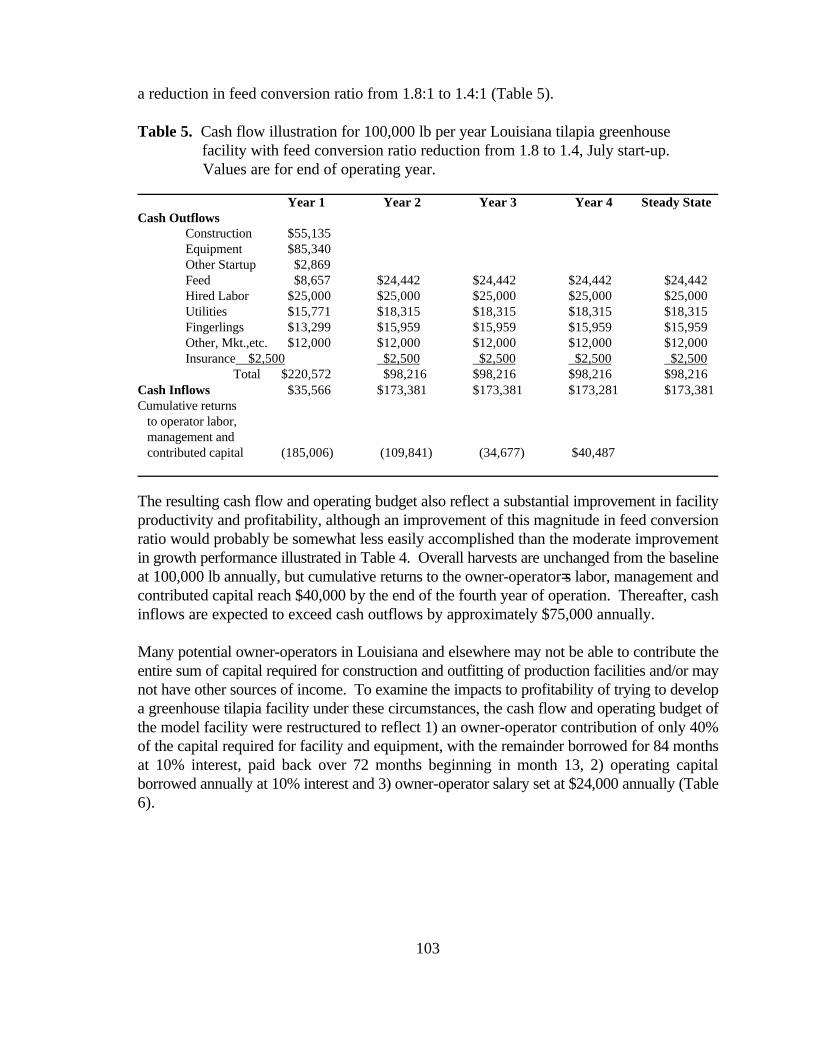
a reduction in feed conversion ratio from 1.8:1 to 1.4:1 (Table 5).
Table 5. Cash flow illustration for 100,000 lb per year Louisiana tilapia greenhouse facility with feed conversion ratio reduction from 1.8 to 1.4, July start-up.
Values are for end of operating year.
Year 1 Year 2 Year 3 Year 4 Steady StateCash Outflows
Construction $55,135Equipment $85,340Other Startup $2,869Feed $8,657 $24,442 $24,442 $24,442 $24,442Hired Labor $25,000 $25,000 $25,000 $25,000 $25,000Utilities $15,771 $18,315 $18,315 $18,315 $18,315Fingerlings $13,299 $15,959 $15,959 $15,959 $15,959Other, Mkt.,etc. $12,000 $12,000 $12,000 $12,000 $12,000Insurance $2,500 $2,500 $2,500 $2,500 $2,500
Total $220,572 $98,216 $98,216 $98,216 $98,216Cash Inflows $35,566 $173,381 $173,381 $173,281 $173,381Cumulative returns to operator labor, management and contributed capital (185,006) (109,841) (34,677) $40,487
The resulting cash flow and operating budget also reflect a substantial improvement in facilityproductivity and profitability, although an improvement of this magnitude in feed conversionratio would probably be somewhat less easily accomplished than the moderate improvementin growth performance illustrated in Table 4. Overall harvests are unchanged from the baselineat 100,000 lb annually, but cumulative returns to the owner-operator=s labor, management andcontributed capital reach $40,000 by the end of the fourth year of operation. Thereafter, cashinflows are expected to exceed cash outflows by approximately $75,000 annually.
Many potential owner-operators in Louisiana and elsewhere may not be able to contribute theentire sum of capital required for construction and outfitting of production facilities and/or maynot have other sources of income. To examine the impacts to profitability of trying to developa greenhouse tilapia facility under these circumstances, the cash flow and operating budget ofthe model facility were restructured to reflect 1) an owner-operator contribution of only 40%of the capital required for facility and equipment, with the remainder borrowed for 84 monthsat 10% interest, paid back over 72 months beginning in month 13, 2) operating capitalborrowed annually at 10% interest and 3) owner-operator salary set at $24,000 annually (Table6).

104
Table 6. Cash flow illustration for 100,000 lb per year Louisiana tilapia greenhouse facility, with 60% of initial construction, equipment and other startup costs borrowed at 10% interest for 84 months (repaid over 72 months beginning in year 2)
and an annual operating loan at 10% interest with operating costs including $24,000 owner/operator annual salary.Year 1 Year 2 Year 3 Year 4 Year 5 Year 6 Year 7 Year 8 Year 9 Year 10 Year 11 Steady State
Cash OutflowsConstruction 55,135Equipment 85,340Other Startup $2,869Principal & Interest $0 33,790 33,790 33,790 33,790 33,790 33,790Feed $11,420 31,428 31,428 31,428 31,428 31,428 31,428 31,428 31,428 31,428 31,428 $31,428Hired Labor $25,000 25,000 25,000 25,000 25,000 25,000 25,000 25,000 25,000 25,000 25,000 $25,000Owner Labor/Mgt. $24,000 24,000 24,000 24,000 24,000 24,000 24,000 24,000 24,000 24,000 24,000 $24,000Utilities $15,771 18,315 18,315 18,315 18,315 18,315 18,315 18,315 18,315 18,315 18,315 $18,315Fingerlings $13,299 15,959 15,959 15,959 15,959 15,959 15,959 15,959 15,959 15,959 15,959 $15,959Other, Mkt.,etc. $12,000 12,000 12,000 12,000 12,000 12,000 12,000 12,000 12,000 12,000 12,000 $12,000Operating Interest $5,719 7,105 7,105 7,105 7,105 7,105 7,105 7,105 7,105 7,105 7,105 $7,105Insurance $2,500 2,500 2,500 2,500 2,500 2,500 2,500 2,500 2,500 2,500 2,500 $2,500
Total $253,054 170,098 170,098 170,098 170,098 170,098 170,098 136,307 136,307 136,307 136,307 $136,307
Cash InflowsLoan $86,000Revenue $35,566 173,381 173,381 173,381 173,381 173,381 173,381 173,381 173,381 173,381 173,381 $173,381
Cumulative returns to operator labor, management and contributed capital (131,481)(128,198)(124,915)(121,632)(118,348)(115,065)(111,782) (74,709) (37,635) (561) $36,512

105
An examination of Table 6 suggests this scenario approaches the limits of debt load andowner-operator compensation the model facility can sustain. The level of debt prior to year8 leaves little room for crop failures or for market prices to decrease. Prior to this point,system failures or unforeseen changes in markets could prove devastating. Minorimprovements in growth and feed conversion could be expected to provide some increasedlevel of >breathing room= in this area, but overall cumulative returns to the owner-operator=slabor, management and contributed capital fail to reach positive numbers until early in theeleventh year of operation. Thereafter, cash inflows are expected to exceed cash outflowsby approximately $37,000 annually, with an additional $24,000 salary directly to the owner-operator.
Summary
The cash flow illustrations and operating budgets developed suggest that even minordifferences in inputs, operational management or debt structure can impact the probability ofsuccess or failure in identical recirculating systems. An improvement from 8.5 to 8 monthsaverage growout period was more beneficial than a reduction of feed conversion ratio from1.8 to 1.4. Combined impacts of borrowing 60% of startup funds, annual financing ofoperating costs and a $24,000 annual salary draw for the owner-operator more than doubledthe positive cash flow horizon and left no possibility for profitable operation at prices below1996-8 averages.
References
Eguia, M.R.R. and R.V. Eguia. “Growth response of three Oreochromis niloticus strains to feed restriction.”Bamidgeh 45(1993):8-17. Eknath, A.E., M.M. Tayamen, M.S. Palada-de Vera, J.C. Danting, R.A. Reyes, E.E. Dionisio, J.B. Capili, H.L.Bolivar, T.A. Abella, A.V. Circa, H.B. Bentsen, T. Gjedrem and R.S.V. Pullin. “Genetic improvement of farmedtilapias: The growth performance of eight strains of Oreochromis niloticus tested in different farm environments.”Aquaculture 111(1993):171-188
Lutz, C.G. “Development of a tank-based tilapia industry in Louisiana.” Successes and Failures in CommercialRecirculating Aquaculture. Ithaca, NY: Northeast Regional Agricultural Engineering Service. 1996. Lutz, C.G. & Roberts K.J. “Greenhouse tilapia production in Louisiana - construction, management and costanalysis.” World Aquaculture ‘97 Book of Abstracts. Baton Rouge, LA: World Aquaculture Society. 1997.
Malone, R.F. and DeLosReyes. “Interim design criteria for warmwater recirculating systems employing floatingbead filters and blown air.” World Aquaculture ‘97 Book of Abstracts. Baton Rouge, LA: World AquacultureSociety. 1997.
Summerfelt, S.T., Hankins, J.A., Summerfelt, S.R. and Heinen, J.M. "Modeling Continuous Culture with PeriodicStocking and Selective Harvesting to Measure the Effect on Productivity and Biomass Capacity of Fish CultureSystems." Techniques for Modern Aquaculture. St. Joseph, Michigan: American Society of AgriculturalEngineers. 1993.

106
Economic Analysis of Land-Based Summer FlounderAquaculture Systems Under Uncertainty
James L. Anderson, Professor David Zucker, Graduate Research Assistant
Department of Environmental & Natural Resource EconomicsUniversity of Rhode Island
Lippitt Hall5 Lippitt Rd.
Kingston, RI 02881
Abstract
Firms practicing land-based aquaculture face both technological and marketing challenges.
When rearing a relatively new aquaculture species, such as summer flounder (Paralichthys
dentatus), growers face uncertainty in areas such as: mortality, growth rates, feed
conversion, and a variety of technical parameters. In addition, given relatively high costs
plus the high degree of uncertainty, growers must generally target niche markets, such as
live markets, which adds another level of sales and price uncertainty.
This research develops a simulation model for land-based summer flounder systems that
incorporates many aspects of uncertainty. The primary output is an expected distribution
for net returns under various operating conditions and marketing strategies. With this
model, various systems can be evaluated in terms of expected returns and the degree of
uncertainty of the returns. Two specific examples are explored. One addresses the
likelihood of system failure; the other focuses on the comparison of selling to live versus
sushi-grade summer flounder markets.

107
Strategic Management -- Some Tools to HelpPrepare for the Future
Patrick D. O'RourkeProfessor of Agribusiness Management
Department of AgricultureIllinois State University
INTRODUCTION
Would you like to improve your chances of success with your next risky investment inrecirculating aquaculture system production?
The goal of this article is to introduce the reader to some important considerations in thedecision to invest in a recirculating aquaculture system (RAS). Some tools - methods ofevaluating the business, the competition and the market - are introduced. The overalltheme is managing strategically, which includes planning the business.
The overall focus of this symposium is "on the principles of economics needed toestablish and sustain RAS. It is aimed at informing and educating potential and existingrecirculating business in this critical area."
Dr. Charles W Coale wrote in his paper presented in 1996 at the first of these annualconferences "An effective management system must be planned and implemented togenerate sustained profits and growth for the RAS firm. …. Marketing and distributionplans should be developed with marketing budgets drawn BEFORE stocking theproduction system with fish. (The bolding is mine.)
Dr. Fred Conte wrote a WRAC pamphlet in 1992 on Evaluation of a Freshwater Site forAquaculture Potential. While not specifically dealing with investing in a RAS, he wrote,"Potential developers and investors interested in aquaculture need information that allowsthem to assess an existing or potential business. They need information that allows anintelligent assessment of the level of risk associated with establishment or investment in aviable business or in an R&D venture."
Dr. Conte then identified three categories into which aquacultural businesses might beassigned (with some overlap and mixing possible). He suggested, and this author agrees,each category exhibited a different degree of risk. The first category was "R&DAqauculture". Most of the business revenues come from venture capital investors,consulting fees, government grants or sales of turnkey systems for which only the sellerhas evidence of success. The level of risk would be great.
The second category was "Transitional R&D Aquaculture". Business revenues stilldepend heavily on investors, grants and consulting fees; however, the share of revenues

108
coming from sales of cultured product has increased and the share coming from sales ofturnkey systems has become unimportant. The level of risk would be reduced dependingon the track record and business plan/strategy.
The third category was "Viable Aquaculture Production". Business revenues areprimarily based on sales of cultured product. Investors are usually shareholders orpartners in the business, which may support expansion with a combination of proventechnologies and innovation. This category would have the lowest level of risk amongthe three categories. Even a RAS business in this category would be exposed to the risksassociated with any agriculture production enterprise. A person's tolerance for risk anduncertainty and their risk management skills may be important determinants of success inunderstanding and managing the agriculture risks associated with; production, marketing,financial, legal and human resource issues/problems.
The risks in aquaculture production are real and are significant. Investments in the bestmanaged and operated RAS will still be classified as relatively high risk investments and;therefore, typically deserving (in a market sense) of higher returns.
Assumption Of Rationality
There are many books, pamphlets, video tapes, college and extension classes, Internetsites, software programs and consultants available for anyone to use in developing andorganizing information to support the decisions related to investing in an RAS. Somehelp with business planning, strategic management, financial evaluation and marketaudits and strategies. Some are designed to help the investor understand the expectedrisks and returns of the investment while others are designed to help sell the investmentopportunity to other investors. With all the helpful people and materials that have beenavailable for some time, it is interesting that we still have any failures of RAS businesses.
Those who invest in aquaculture (RAS in this instance) are presumably rational people.One would expect them to compare the satisfaction they would expect to receive fromtheir use of money, labor and management skill in a RAS to the satisfaction they wouldexpect in alternative uses, or, at least the next best alternative use of those resources. Inother words, the concept of opportunity costs should be well understood and applied.
No one in the past, present or future has or will purposely invest in RAS productionwithout at least the belief that the investment is the best thing to do with their resources.The work is too demanding to do it for fun. There may be some non-monetarysatisfactions from working with fish, producing food (being a farmer), being on the leadedge of an industry, being recognized as an innovator and entrepreneur or living in a ruralarea. Those put aside; the investor would still be expected to invest his resources wherethey would be expected to earn the highest return.
It is with that understanding that some tools useful in strategically managing a businessare discussed in this article. Time and space are too limited to be complete, so what iscovered is an introduction to very easy to use yet powerful decision support tools.

109
Strategic Management and Planning
Some definitions may be helpful in understanding what is meant by managingstrategically. These definitions and tools are covered in more detail in Thompson andStrickland.
Strategy: The pattern of actions which managers use to achieve the enterprise's objectives.The company's actual strategy is part proactive and part reactive.
StrategyFormulation:
The direction setting management function of conceptualizing the companiesmission, setting performance objectives and crafting strategies. The end product ofstrategy formulation is a strategic plan.
Strategic Plan: Statement outlining the company's mission and future direction, short and long-term performance targets, and strategies.
StrategyImplementation:
The whole range of managerial activities associated with putting the chosenstrategies in place, supervising the pursuit of targeted results and achieving thosetargeted results.
Some of the tools used in managing strategically are similar to and useful in constructingwhat are usually know as the "business plan" or the "marketing plan" for a business.Strategy could be called management's game plan for satisfying customers, improvingthe RAS business's position in the market, and achieving predetermined performancetargets. It provides a guide for how to conduct business and helps management makewell thought out choices among alternative courses of action. It is a road map to desiredresults.
Strategy-making is fundamentally a market-driven entrepreneurial activity risk-taking,venturesomeness, business creativity, and an eye for spotting emerging marketopportunities. One needs to cultivate "outside-in thinking versus inside-out thinking."The latter may cause management to miss outside threats or opportunities because it isnot a market-driven and customer-driven approach
RAS business strategies can't be truly market and customer-driven without RAS businesswide, outside-in entrepreneurial character dedicated to superior customer perceived valueand achieving sustainable competitive advantage. The strategic management processconsists of several interrelated managerial tasks or steps.
FIVE INTERRELATED MANAGERIAL TASKS1 Deciding what business the RAS business will be in and forming a strategic vision of where
the RAS business needs to be headed -- in effect, infusing the RAS business with a sense ofpurpose, providing long-term direction, and establishing a clear mission to be accomplished.
2 Converting the strategic vision and mission into measurable objectives and performancetargets.
3 Crafting a strategy to achieve the desired results.4 Implementing and executing the chosen strategy efficiently and effectively.5 Evaluating performance, reviewing new developments, and initiating corrective adjustments
in long-term direction, objectives, strategy, or implementation in light of actual experience,changing conditions, new ideas and new opportunities.
Strategy-making is a dynamic process where a RAS business’s mission, objectives,

110
strategies, and implementation are always being reevaluated, refined and recast basedon real time events and trends. In actual strategy-making process there are no clearboundaries between the tasks.
Strategies with one of or combinations of the following three generic competitiveapproaches are often found to be most appropriate.
THE THREE GENERIC COMPETITIVE APPROACHES1 Striving to be the industry's low-cost producer thereby aiming for a cost-based competitive
advantage over rivals,2 Pursuing differentiation based on such advantages as quality, performance, service, styling,
technological superiority, or unusually good value, and3 Focusing on a narrow market niche and winning a competitive edge by doing a better job
than rivals of serving the special needs and tastes of its buyers.
Industry and Competitive Analysis
Industry and competitive analysis utilizes a set of tools/concepts to develop a clearerpicture of conditions in the industry and the nature and strength of the competitive forces.It helps one think strategically and form conclusions concerning whether the industryrepresents an attractive investment opportunity relative to other investments.
The purpose of industry and competitive analysis is to develop thorough answers to sevenquestions by probing for facts.
Question Example1 What are the aquaculture industry's dominant
economic traits?Economies of scaleEase of entry and exitCapital requirementsScope of competitive rivalry
2 Which of the five competitive forces are mostat work in the aquaculture industry and howstrong is each?
Rivalry among competitorsThreat of entryCompetition from substitutesPower of suppliersPower of customers
3 What are the drivers of change in theaquaculture industry and what impacts will theyhave?
Customer attitudes & demographicsRegulationIncreasing globalizationPopulation and income growth
4 Which companies are in the strongest/weakestcompetitive positions of importance to thisenterprise?
ImportersPond producersSeafood captureOther livestock firms
5 Which players are likely to make whichcompetitive moves and when?
6 What are the key success factors, which willdetermine competitive success or failure?
Technological know-howLow cost production and distributionImage & ability to differentiate
7 Finally, how attractive is the industry, in termsof prospects for above average profitability,based on the information assembled?

111
Company Situation Analysis
After thinking strategically about the business's external situation, one evaluates thebusiness's strategic position in the environment. The approach in company situationanalysis is to focus on the following five questions.
Question Example1 How well is the present strategy working?
Or, for a new company, how well is thestrategy working for a similar company?
Market share, GrowthReturn on assetsReturn on equity
2 What are the company's strengths,weaknesses, opportunities and threats?
Internal Strengths & WeaknessesExternal Opportunities & Threats
3 Are the aquaculture business's costs andprices competitive
Could become "core competency" and leverage"sustainable competitive advantage"
4 How strong is the business's competitiveposition? Or How strong would thecompetitive position be?
Rank Vs competitors on KSA's etcCompetitive advantages/disadvantages?Ability to defend vis-a-vis driving forces
5 What strategic issues/problems doesmanagement need to address in forming aneffective strategic action plan?
The five competitive forces -- strategy?Is the company vulnerable to competitive attackfrom one or more rivals?
Swot Analysis
Evaluating a business's internal strengths and weaknesses and its external opportunitiesand threats is known as a SWOT analysis. With SWOT analysis one can follow the basicprinciple that whatever strategy is taken, it must produce a good fit between thebusiness's internal capabilities and its external situation. The following list represent justa few examples of potential strengths, weaknesses, opportunities and threats a RAS mayexperience.
INTERNAL STRENGTHScore competencies in key areas proprietary technology (patents)respected by buyers adequate financial strengthutilizes economies of scale proven managementcost advantages superior technical skills
INTERNAL WEAKNESSESno clear strategic direction too narrow a product lineobsolete facilities or equipment weak market imageno significant R & D poorly organized distribution networkhigher unit cost relative to rivals subpar profitability due to .....
EXTERNAL OPPORTUNITIESgo after additional customer markets diversify into related productscustomer needs broader than product line Vertical/horizontal integration possibilityrival firms complacent re: market falling trade barriers
EXTERNAL THREATSlower cost foreign competitor new costly regulationsincreasing bargaining power of customer or supplier falling trade barrierschanging buyer tastes or needs increasing sales of substitute items

112
This has been a quick review of some tools useful in preparing for the future in RASproduction opportunities. Using these tools well will require a significant investment oftime, but, it may improve your chances of success with your next risky investment inRAS. The following reference list contains many sources useful in developing businessplans, market plans and strategic management skills.
References
Aguayo, Rafael. Dr. Deming: The American Who Taught The Japanese About Quality.NewYork: Simon & Schuster, 1990.
Brandenburger,Adam & Barry J. Nalebuff. Co-Opetition. NewYork: Doubleday, 1996.
Brigham, Eugene F., and Louis C. Gapenski. Financial Management. Fort Worth: The DrydenPress, 1994.
Burton, E. James, and W. Blan McBride. Total Business Planning. NewYork: John Wiley &Sons Inc.,1991.
Champy, James. Reengineering Management; The Mandate For New Leadership. NewYork:HarperCollins Publishers, 1995.
Clancy, Kevin J., And Robert S. Shulman. The Marketing Revolution. NewYork: HarperCollinsPublishers, 1991.
Coale, Charles W, Jr. "Marketing Fish and Shellfish Products Grown in a RecirculatingAquacultural System (RAS)." Successes and Failures in Commercial RecirculatingAquaculture. Proceedings Volume I (1996): pages 116-127.
Conte, Fred S. Evaluation of a freshwater site for aquaculture potential. Western RegionalAquaculture Center Publication, WRAC No. 92-101. 1992.
Cramer, Gail L. and Clarence W. Jensen. Agricultural Economics and Agribusiness, Sixth Ed.New York: John Wiley & Sons, Inc. 1994.
Finnie, William C. Hands-On Strategy. NewYork: John Wiley & Sons, 1994.
George, Stephen, and Arnold Weimerskirch. Total Quality Management. NewYork: John Wiley& Sons Inc., 1994.
Goldman, Steven L., Roger N. Nagel, and Kenneth Preiss. Strategies For Enriching TheCustomer. NewYork: Van Nostrand Reinhols, 1995.
Hamel, Gary & C.K. Prahalad. Competing For The Future. Boston: Harvard Business SchoolPress, 1994.
Hargrove, Robert. Marketing Coaching. San Diego: Pfieffer & Company, 1995.
Hill, Charles W.L., and Gareth R. Jones. Strategic Management; An Integrated Approach (ThirdEdition). Boston: Houghton Mifflin Company, 1995.
Marin, Don. Team Think; Using the Sports Connection to Develop, Motivate, and Manage aWinning Business Team. NewYork: Peguin Books, 1993.
Miller, Alex. Strategic Management, Third Ed. Bosten: Irwin/McGraw-Hill. 1998.
Miller, Paul C. with Tom Gorman. Big League Business Thinking. Englewood Cliffs: PrenticeHall, 1994.

113
O'Rourke, Patrick D. "The Economics of Recirculating Aquaculture Systems." Successes andFailures in Commercial Recirculating Aquaculture. Proceedings Volume I (1996): pages61-78.
Ostrenge, Michael R., Terrence R. Ozan, Robert D Mollhattan, and Marcus D. Harwood. TheErnst & Young Guide To Total Cost Management. NewYork: John Wiley & Sons, 1992.
Perry, Lee Tom, Randall G. Stott, and W. Norman Smallwood. Real-Time Strategy; ImprovisingTeam-Based Planning For A Fast Changing World. NewYork: McGraw-Hill Inc., 1995.
Peters, Tom. Liberation Management. NewYork: Ballantine Books, 1992.
Peters, Tom. The Pursuit of WOW! NewYork: Vintage Books, 1994.
Peters, Tom. The Tom Peters Seminar. NewYork: Vintage Books, 1994.
Pinson, Linda and Jerry Jinnett. Anatomy of A Business Plan, Third Ed. USA: UpstartPublishing Company. 1996.
Pinson, Linda. Guerrilla Business: Automate Your Business Plan, 1.0 for Windows ® 3.1 orWindows ® 95. USA: Houghton Mifflin interactive. 1997.
Salant, Priscilla, and Don A. Dillman. How To Conduct Your Own Survey. NewYork: JohnWiley & Sons Inc.,1994.
Senge, Peter M., Art Kleiner, Charlotte Roberts, Richard B. Ross, and Bryan J. Smith. The FifthDiscipline Fieldbook. NewYork: Doubleday, 1994.
Shapiro, Eileen C. FAD; Surfing in the Boardroom. Reading: Addison-Wesley Publishing Co.,1995.
Tang, Victor, and Roy Bauer. Competitive Dominance; Beyond Strategic Advantage and TotalQuality Management. NewYork: Van Nostrand Reinhold, 1995.
Thomas, Robert J. New Product Development; Managing and Forecasting for Strategic Success.NewYork: John Wiley & Sons Inc., 1993.
Thompson, Arthur A. Jr., and A.J. Strickland III. Strategic Management; Concepts and Cases(Ninth Edition). Chicago: Irwin, 1996.
Treacy, Michael and Fred Wiersema. The Discipline of Market Leaders. Reading: Addison-Wesley Publishing Co., 1995.
USDA Risk Management Agency. Introduction to Risk Management, UnderstandingAgricultural Risks: Production, Marketing, Financial, Legal and Human Resources.Wash. D.C.: USDA.
Vance, Mike and Diane Deacon. Think Out Of The Box. Franklin Lakes: Career Press, 1995.
Webster, Frederick E. Jr. Market-Driven Management; Using The New Marketing Concept ToCreate A Customer-Oriented Company. NewYork: John Wiley & Sons Inc., 1994.
Whiteley, Richard & Diane Hessan. Customer Centered Growth. Reading: Addison-WesleyPublishing Co., 1996.
Wilson, Larry with Hersch Wilson. Stop Selling, Start Partnering; The New Thinking AboutFinding And Keeping Customers. Essex Junction: Oliver Wight Publications, Inc., 1994.
Wing, Michael J. Talking With Your Customers; What They Will Tell You About There Business.United States: Dearborn Financial Publishing, 1993.

114
What Lenders Want: Financing Your Aquaculture Enterprise
Patricia Farish LaceyVirginia Seafood Research and Extension Center
Virginia TechHampton, Virginia
Introduction
Aquaculture is a “new” industry. Though fish have been farmed for thousands of yearsaround the world, lenders view loan applications as higher risk enterprises because oftheir novelty. Because of this it is even more necessary than in other business plans, topresent a clear, well projected image of the business.
The business plan, accompanied by the loan application package, is the one instrumentthe entrepreneur has available to “sell” his business to the lending institution. The planshould provide a crystal clear impression of the technical, marketing and financial aspectsof the business. The lender, who may not know aquaculture operations, should be able tounderstand as much of the proposed business plan as possible.
What Lenders Want
Lenders surveyed for this paper stated that first and foremost they wanted a realisticdocument about the business. Reasonable financial statements, clear marketing andtechnical information and relevant analysis of potential problems the business could faceranked highly on their list.
Lenders also use certain flexible criteria to evaluate loans, including cash flowstatements, financial ratios, ability to provide collateral, experience level of managementand product market status.
The Business Plan
Lenders prefer to see a fully developed business plan for the operation. (See Appendixfor an outline of a model business plan.) Survey respondents indicated that a plan thatread well, was convincing and well documented would receive further evaluation on amore positive note than a “scantily” prepared submission.
Financial Statements
Lenders prefer minimum of four years of financial statements including most importantlythe cash flow statement and income statement. Data should be projected monthly for thefirst two years, then quarterly thereafter. Most lenders indicated that they preferred

115
sensitivity analysis be conducted on the financials to show the impact of changes to thefirm. (Changes could be anything from fish and feed prices to increased mortality.)
Financial Analysis and Ratios
At the top of the lenders list was the need for a cash flow statement. The primaryquestion to be addressed, which if negative, will end the loan process, is “Can thecompany meet its financial obligations?” A positive cash flow throughout the projectionperiod is essential. Lenders do, however understand the timing of harvests and expect theborrower to adequately fund the business either through debt or equity, in order toprevent negative cash flow periods.
The second most important financial aspect was the debt/equity ratio. This ratio is totalliabilities divided by total equity. Needless to say, the higher this ratio, the riskier thebusiness. The lender wants personal investment in the business. Survey respondentsindicated that lenders required, depending on many other factors, from 10-30 percentpersonal investment in a business.
Most lenders stated that collateral was a tricky issue. Average stated required collateralwas 60%. This is a qualified statement, that the stronger the proposal, the more flexiblecollateral requirements are.
Marketing
Lenders are taking a new and intensified look at the marketing plans of potentialcompanies. They require price and quantity history. They want reassurance that the firmhas a viable market that will perform to the expectations of your financial projections. Ifpossible, show market growth trends; provide intent to purchase agreements anddocument any supply deficits possible.
Other Issues
Lenders are also interested in aspects other than financial ones. A very important issue isthe experience level of the management team. Most survey respondents indicated thatwithout adequate experience or training in the field, they were unlikely to fund a newventure. If management is not experienced in the field of aquaculture, it helps theapplication to hire someone on the management team who is.
Another critical issue for lenders is the willingness of entrepreneurs to sign personalguarantees for the debt. One respondent indicated that to his bank, this indicated apersonal belief and trust in the business. Most banks indicated that they require personalguarantees on the majority of their loans of this type.
One surprising item that bankers considered was personal ability to survive a failure. Aspersonal guarantees are nearly always required, the banks consider whether the individual

116
owners could survive the failure of the business. One lender stated, “If the business fails,there is one bankruptcy. There shouldn’t have to be two.”
Summary
Lenders want to finance successful businesses. The guidelines lenders use to evaluateloan applications are to protect not only themselves, but the clients as well. Evaluate thebusiness plan on the criteria that lenders use before you submit it. This will increaseprobability of financing and a successful venture.
Appendix: Parts of a Business Plan
Executive Summary
The most important part of a business plan, particularly for those trying to finance a newbusiness or expansion of an existing business is the Executive Summary. This is the firstexposure to the business concept and plan that most lenders will have. Therefore, it mustbe concise, compelling and informative. It must entice and convince the reader that therest of the plan, and therefore the business, has merit. The Executive Summary shouldaddress these issues:
1. How the company is organized (corporation, partnership, etc.), its stage ofdevelopment (currently in operation or on paper) and the company's mission.
2. (Was it a fit with available resources or training? Was an unmet marketopportunity recognized? What are the products to be offered?)
3. What is the target market?4. Why can this company meet market needs and face the relative competition? (In
other words, what is your competitive advantage or edge?)5. Why is management capable of running this particular business? (Indicate
training, background, previous employment, etc.)6. Briefly list milestones for the business. For example, 1 million pounds per year
by year 2, when the first products will be shipped, what percentage of whatmarkets do you think you can obtain and by when.
7. Specify your financing plan. How much equity from owners do you expect?How much credit from lenders will you require? How will lenders be repaid andhow will investors be compensated.
Company Description
1. Legal name and form of businessThe company should have a legal status for the state in which it operates. This could be aprivately held corporation, a publicly traded corporation, a partnership, a limitedpartnership, an individual proprietorship and many permutations in between. It shouldhave a legal name for this status. This is the name the business will be known to the statein which it operates and to the Internal Revenue Service. Include the date of legalformation.

117
2. Company's mission and objectivesThis should describe what the company's overall goal is and its objectives towardmeeting that goal. A mission could be very general or specific, depending on the natureof the business.3. Top Level ManagementThis will name and describe the qualifications of the business's management team. Stressany particular training, education or experience that will be beneficial to the business.Try to show that all areas of the business (including management, marketing, finance andoperations) are well covered managerially.4. Location and geographical informationThis gives the physical address for the information and any details as to why this locationis favorable for this endeavor.5. Company development stageThis should describe where the company is as of the time of the plan. Is it just a wellresearched business on paper? Is this an expansion or combination of existingbusiness(es)? How much prior experience in this field is the company bringing to thefore?6. Company products and/or servicesWhat does the company offer for sale? Is it live or processed? What does it offer besidesthe physical product? (Do you offer assistance to the buyers in dealing with theproducts? Are consulting services offered?)
Industry Analysis
1. Size and growth trendsWhat is the current size (dollars and quantity) of the industry? Give overall statistics forthe whole industry and specifics for the part (by species and product form) of thesegment. How fast are both the industry and the target segment growing?2. Maturity of industryIs this a mature industry? For most aquaculturists, with the exception of southern catfishfarming and potentially natural spring trout farming, the industry is still in its beginningphases.3. Potential impact of economic factorsWhat impact does the overall performance of the economy have on the business? Forexample, if interest rates are high (and therefore disposable income down), and theproduct is considered a "luxury" as many seafood product are, high interest rates couldhave a depressing effect on sales.4. SeasonalityDoes seasonality play a role in the business5. Technological factorsIs the technology proven? Is it operational in other facilities? Is it operational in researchfacilities? What documentation/data can be provided to support these facts? Are therepatents or proprietary processes that give a competitive edge?6. Regulatory issues and permitsWhat are the significant regulatory guidelines with which the business must comply?How will they be complied with? What permits need to be obtained to operate? When

118
will they be obtained? Do any of the regulatory issues or permits effect this businessdifferently than the competition and why?7. Supply and distributionWhat is the supply situation for the industry and how is it distributed?8. Financial considerationsWhat does it take investment-wise to become a recognized competitor in this industry?How heavy is competition and how does that relate to the need to have heavy cashreserves ("deep pockets")? Are there impending regulatory changes that will requirefurther investment? Consider regulatory agencies defining parameters for growout,treatment, shipping, etc.
The Target Market
1. Demographic/geographic areasWho are the target market consumers? Consider this beyond the distributor. Where dothe end consumers live? Are they ethnic? What is their socio-economic status? Is it agrowing segment of the economy? It is important to consider whom the distributor sellsto, because that will determine the level of his potential sales, and therefore, thecompany’s.2. Lifestyle and psychographicsWhat is the socio-economic buying pattern of the end consumer? Are they convenienceoriented? Is there a definite "lifestyle" associated with heavy users of the product? (Forexample, in predominately two-worker households, you might find many food productspurchased because of convenience. An opposite case, with one stay at home adult,convenience may not be as important. Certain cultural groups may have different valuesplaced on freshness, form, convenience, etc.)3. Purchasing patternsFirst, how does the distributor purchase the product? What size shipments does he preferand how often? How does he distribute the product (time and place)?Does the end consumer purchase the product daily, weekly, monthly or on specialoccasions? How much do they usually purchase at one time? What product form do theyprefer?4. Buying sensitivitiesIs the end consumer extremely sensitive to price fluctuations? Is this product a staple orspecialty product for the consumer? Do they view other species as substitutes for theproduct (which could allow much price sensitivity)? Are there any particular physicalattributes to the product that target consumers prefer? (Examples are size, color, etc.)5. Size and trends of marketIn the particular market segment for the product, in your geographic target, how large isthe market? How is it growing? Is it seasonal? Are there religious and/or other culturalcelebrations that effect demand?
The Competition
1. Competitive positionHow is the company positioned against competitors? What advantages does the company

119
have? What are the disadvantages and how will they be dealt with? How does the pricingand cost structure compare with the competition?2. Market share distributionWhat percentage of the target market does the company intend to acquire? How is thisreasonable? What share does the competition have? How is it distributed among thecompanies?3. Barriers to entryAre there any significant barriers to entry to the target market? Are there contracts,agreements to purchase, etc. that would keep new competition out? Are there financialconsiderations that would effect new competitors? Are there regulatory issues that willeffect the emergence of new competitors?4. Future competitionWhat new competition is suspected in the target market in the future? Are there definiteoperations coming online? How will new competition be dealt with?
Marketing and Sales Strategy
1. The company "message"What is the main thrust of the marketing plan? (For example: We intend to deliver "X"pounds of product on a bi-weekly basis of uniform quality and size product. This willmake it easier on the large distributor as he will no longer have to deal with purchasingirregular amounts at irregular times from natural harvests or smaller suppliers.)2. Marketing vehiclesHow will the marketing message get out? Will conventional advertising, promotionalmailers, personal sales visits, trade shows, etc. be used?3. Strategic partnershipsIs the company involved directly as the only partner/supplier with a distributor(s)? Doesthis relationship make the market more secure? Are there existing sales contracts? If so,how will contingencies such as shortages, excessive mortality, etc. be dealt with?4. Other marketing tacticsWill the company participate in promotional ventures? Is there a quality program thatprovides benefits/reassurances to the buyer? Are volume discounts offered?5. Sales force and structureWhat kind and size of sales force will be hired? How are they organized? How are theirgoals set and what incentives are provided?6. Sales assumptionsAre there any particular assumptions related to sales in the business plan? Are there priceassumptions? Competitive assumptions? How will management deal with divergencefrom stated assumptions if forced by market conditions?
Operations
1. Plant and facilitiesDescribe the physical plant and facilities. Include as an appendix, a floor plan for thefacility. Describe the general geographical area of the plant. Give the operationaladdress for the facility.

120
2. Production planHow much of what product will be produced and at what time intervals? Describe initialstocking plans, harvest plans and expected mortality. Give a breakdown of timeschedules for production.3. Equipment and technologyWhat equipment will be used in the facility? How many tanks? What type of filtrationsystem? How does the system work, in simplified terms? What type of redundant orback-up systems will be in place? What kind of alarm or warning system will be used?Is there documentation that can be provided on the technology and its successful useelsewhere? If so reference it to an appendix.4. Variable labor requirementsWhat are the labor requirements? (This refers to non-managerial labor.) Does it varyseasonally? Is there adequate access to the types of labor needed? Will management“scale-up” labor during the start-up phase? (If so, provide an estimate of the timeschedule for this.)5. Inventory managementHow will inventory be tracked? This will include the fish stock. This also includesinventory of expendable items such as salt, sodium bicarbonate, feed, etc.6. Research and developmentWill the company be conducting any research and development at the facility? Thisincludes testing feeds, new species, water treatments, equipment, etc. Please explainmanagement’s plans and why they will benefit the business. List any cooperatingagencies, universities, and companies.7. Quality controlHow will the quality control system work? Is there a designated person in charge of this?If so, what are their qualifications for the position? What records will be kept regardingquality control? Is this in line with what the industry at large does?8. Capacity utilizationWhat is the full capacity production limit for the facility? Will it be operating at thatlimit? Will the company scale up to that limit? If so, list milestones for reachingcapacity. If the company is not going to be utilizing the facility to capacity, pleaseexplain why.9. Safety, health and environmental concernsIs the company in compliance with all regulatory agencies, including OSHA and EPA?What safety/health programs are in place to protect employees on the job? Will there besafety drills to deal with fire, contaminants, and other dangerous situations? (An examplewould be ozone usage.)10. Management information systemsHow will financial and operational records for your company be kept? Is the companycomputerized? Who has access/control over these systems? Are there adequate back-upprocedures in place?11. Other operational concernsThis is a “catch-all” category for anything that is not covered under one of the othertopics. This is a good place to point out any operational advantages the company mighthave over competitors.

121
Management and Organization
1. Principals and key employeesList all the management and owners and summarize their expected contributions as wellas their qualifications. List any key personnel and their contribution and qualifications.Reference current resumes in the appendix.2. Board of directorsList all board members and explain why they are on the board. Explain any benefitsobtained from having particular board members.3. Consultants/specialistsList any consultants or specialists to be used during the course of operation. This willinclude accountants, attorneys, scientists, laboratories, etc. Explain the compensationplan. Explain what the duties of these consultants are and why they are vital to thebusiness.4. Management to be added If management is to be added later, describe the position and function within thebusiness.5. Organizational chartInclude a reference to the appendix to a full organizational chart for your company.6. Management styleWhat management style will be used? This can be from the informal “management bywalking around” to a more formal directorial style? Explain the reporting system forregular and irregular operations. Explain proper response for operations irregularity.
Development and Exit plans
1. Long term company goalsWhat are the long term goals of the company? Is it expected to vertically or horizontallyintegrate or expand production into other facilities?2. Growth strategyWhat is the growth strategy and how will it be managed and financed?3. MilestonesProvide a narrative and chart pointing out major milestones in the development of thecompany. This includes pre-groundbreaking time, plan writing time, etc.4. Risk evaluationWhat type of model will be used to evaluate risk of continued operations? What type ofmodel will be used to evaluate risk of expanding operations? (This can be as simple as aSWOT analysis combined with financial spreadsheet sensitivity analysis or as complex asa statistical risk assessment.)5. Exit planWhat are the criteria/procedure for voluntarily shutting down the business?
Financial Statements
1. Cash flow statementThe cash flow statement is the easiest and most important of all financial statements. It is

122
a direct statement of cash (revenues) in less cashes (expenses) out, leaving cash on hand.This is an important managerial statement. It is the record of (for historical or realstatements) the ability to meet financial obligations and the forecast of ability to meetpotential obligations..2. Income statementThe income statement is a statement of profitability, not of cash left on hand as in a cashflow statement. The major difference is the inclusion of non-cash items such asdepreciation and other non-cash adjustments. The income statement should be preparedon the same schedule as the cash flow statement.3. Balance sheetMany investors and lenders are interested in the balance sheet. Basically the balancesheet is a statement detailing assets, liabilities and owner’s equity. The basicmathematical structure of the balance sheet is simple: assets equal liabilities plusowner’s equity. This is normally prepared annually, but in start-up phases, lenders maylike to see the statement quarterly.4. Break even and other analysesPerform analysis on your financial statements to ascertain the financial health of thebusiness. Also, financial institutions will analyze the statements. Some analysis shouldbe presented in the business plan. These are some of the more relevant ones.
a. break even analysis
b. liquidity ratios
current ratio = current assets / current liabilities
quick ratio = (current assets - inventory) / current liabilities
c. leverage ratios
debt to assets = total debt / total assets
times interest earned = earnings before interest and taxes / interest charges
d. activity ratios
inventory turnover = sales / inventory
fixed assets turnover = sales / net fixed assets
total assets turnover = sales / total assets
e. profitability ratios
profit margin = net income / sales

123
basic earning power = earnings before interest and taxes / total assets
return on total assets = net income / total assets
return on equity = net income / equity
5. Plan assumptionsList any assumptions that went into making the plan. Include areas such as funding,potential employees, etc. There should be a separate list of assumptions/explanations forall line items on the financial statements.
Appendix
This section will include all items too detailed for the body of the plan or items that donot fit any particular category. Any items referenced in the body (such as resumes,explanations of terms, contracts, etc.) should appear here. Letters of intent to purchase,supply consult, or assist belong here, after being referenced in the main text. Any otherdocumentation requested by investors or lenders may be referenced and placed here. Ifthe appendix is lengthy, it is often preferable to give it its own sub-table of contents.

124
Recirculating Aquaculture System in Japan
Haruo HondaResearch Fellow, Biology Department, Abiko Research Laboratory,
Central Research Institute of Electric Power Industry
Status of aquaculture in Japan
With the establishment of the 200 miles economic zone, aquaculture of fish are becomingmore and more important in Japan. By 1992, the aquaculture production of Japaneseflounder (Aquaculture 7,114 tons: Fishing catch 6,187 tons), red sea bream (65,699 tons:14,243 tons) and yellow tail (148,691 tons: 55,427 tons) exceeded their fishing catch.And this status has continued in 1995 though there are some fluctuations in Japaneseflounder. Out of the total aquaculture production in 1995, that of coastal culture was1,314,551 tons (94.5%), and that of freshwater culture was 75,123 tons (5.5%).
Problems of aquaculture with open systems
Most of the saltwater fish culture is managed with net cages on the coast of Japan. Somekind of fish, such as Japanese flounder and Japanese prawn (Kuruma prawn) are rearedwith land based tanks by flow through method. Because these two types of fish culturedepend on the natural sea and seawater, fish growth and management of the systems areaffected by seasonal changes, weather conditions and other factors. Moreover, these twoopen fish culture systems discharge feces of rearing fish and leftovers directly to the sea.Therefore in some areas, they caused deterioration of the culture ground and waterpollution. And sea areas suitable for the coastal aquaculture have become more and morelimited. The another problem of flow through system is that the sea water taken from thesea is returned to it in only one to two hours. To use of electric power more effectively,this process should be improved. For freshwater aquaculture with race way (flowthrough), insufficiency of suitable water resources for aquaculture has become one oflarge issue.
Advantages of recirculating fish culture system
On the other hand, closed recirculating fish culture systems have the advantage of usingvery small quantities water for fish production compared with flow through systems.Therefore, it is easier to maintain an optimum temperature for rearing species and also todisinfect the rearing water. So we are able to shorten the rearing period to make a marketsize of fish. Closed systems have another advantages of less direct impact on the aquaticenvironment than open systems when the waste materials and discharge water from thesystem are managed properly.
Historical overview of studies on recirculating fish culture system
To save culture water, effective use of energy (oil and/or electricity), effective use of

125
land, and prevent pollution on environment, many studies have been conducted in theworld during the past two decades (van Rijn, 1996; Losordo, 1998).
About forty years ago first scientific report on recirculating fish culture system waswritten by Saeki (1958) in Japan. Through some laboratory experiments, he studiedoxygen uptake and degradation capacity of sand bed filter and he showed ammoniaoxidation rate of sand in filter bed is 0.14 mg-ammonia per day per 10 g of sand. And heestimated that 300 g weight of filter sand should be used for culturing for 10 g of fish.Based on this standard design, he constructed three closed recirculating systems of 200 to500 m3 of water volume with gravel as filter media, and he carried out carp culture testsfrom 1961 to 1964 (Saeki, 1965). However, these systems are not in existence today.Hirayama (1965, 1966, 1974) also studied oxygen uptake and degradation capacity ofsand bed filter for saltwater fish culture. And he also studied on the accumulation ofdissolved organic substances in closed recirculation culture systems (1988).
During from 1977 to 1981, Mie Prefecture Fisheries Experimental Station studied oneffective use of rearing water for Japanese eel (Anguilla japonica) culture with closedrecirculating fish culture system. They estimated that the upper limit rearing density wasat 25 to 30 kg/ m3 when the supply of oxygen was done by aeration. Also they found thatthere was no difference on growth of eel when the water replacement rate were from 2 to20 % per day. And they used a plastic filter media for closed fish culture for the first timein Japan.
In 1986, we (CRIEPI) have started the studies to develop closed recirculating fish culturesystems for Japanese flounder from the viewpoint of obtaining optimum conditions forfish using electric power and also reducing the impact on the aquatic environment.
Recirculating aquaculture systems in Japan
Eel
Due to high value of both land and elvers, more and more intensive culture methods havebeen developed. The out door still water earthen ponds have been replaced by indoortanks, built in green house, with water heating systems, aeration systems and waterrecirculation systems. Almost systems consist of octagonal shaped concrete tanks,settling tanks and pumps. Some of them also have gravel or plastic biological filter bed.However these systems appearance differ from eel production recirculating systems inEurope countries. In these system, rearing densities are from 20 to 40 kg per m3 of water,flow through rates range from once per hour to per day, and water replacement rates are 5to 15 % per day depending on fish size reared. This type systems are common in Japan.And some imported systems such as Danish Type with bio-drum do operate now inJapan.
Rainbow trout
Culture of rainbow trout needs a large amount of water and high replacement rate at near

126
100% per hour. There is a trout farm adopted recirculating system to rear juveniles dueto insufficient spring water supply in Nagano Prefecture. A system consists of a slightlysloped rectangular fish tank, a filter for waste solids removal and a biological filter fornitrification. The solid removal filter with fluidized small pieces of plastic mat resemblesto low density plastic floating bead filter though the direction of water flow is downward.The total water volume of the system is 30 m3. The flow through rate is once per 20 to30 minutes. Although water replacement rate is about 50 % per day, water volume usedin a day is only 2 to 4 % comparing with ordinary flow through system.
Ayu
The system mentioned above is also adapted to rear juvenile Ayu (Plecoglossus altivelis).And Kanagawa Prefecture Fisheries Experimental Station has a experimental system forAyu.
Japanese flounder
Our system (CRIEPI-type) was planned to produce 2,000 fish of 500 g in body weight(1,000 kg of fish), which is the minimum commercial size for cultured flounder in Japan.The system consisted of a fish tank (6 m in diameter, 16 m3 of water volume), a settlingtank (1 m3), two biological filters (3 and 2 m3), a heating-cooling unit (heat-pump 19,000kcal/h), a circulation pump (480 L/min), an UV light (540 w), blowers (270 w by 3) andtotal water volume adjusted 22 m3. The minimum necessities of filter media, aeratorcapacity, seawater for operation and bottom area of fish tank were calculated based on theresults of other experiments such as upper limit rearing density: about 40 kg/m2 (400gfish in body weight), ammonia excretion rate: 250 mg/day in 500 g fish, ammoniaoxidation rate of well conditioned biological filters (223 mg/L/day) and respiration rate ofthe fish (Honda, 1988; Honda et al., 1991; Kikuchi et al., 1990, 1991,1992,1994). Wealso have two 10 m3 systems at Akagi Testing Center in Gunma Prefecture.
Besides our systems, there are other two types of recirculation aquaculture systems forflounder in Japan now. In 1997, JIFAS (Japan International food and AquacultureSociety) has started the evaluation on the system consisting of some imported equipmentfrom foreign countries with summer flounder from USA. The system consists of fourfish tanks (5 m3), some water treatment equipment such as particle trap, micro screenfilter, ozone generator, form fractionator, UV light, trickling filter, mixed bead filter,oxygenator, and a heating-cooling unit. The system with bromine free artificial seawateroperates now in Saitama Prefecture. And Hokkaido Industrial Technology Center has aJFAS-type system consists of nine fish tanks of 3 m3.
Another one is called KSK-type after the name of the company dealing the system. Thesystem consists of a fish tank and a biological filter. A pilot system has operated in ShigaPrefecture from 1997.

127
Puffer
A CRIEPI-type system consists of four fish tanks of 5 m in diameter has operated toproduce Tora-fugu (Fugu rubripes rubripes) now in Shimane Prefecture from 1996.
This system is managed by a local fisheries association.
Other species
There are some trials to rear some saltwater organisms such as scorpaenid fish, abaloneand others with recirculating aquaculture system.
Operation and variable cost of recirculating aquaculture system
We conducted rearing experiment with 2,000 juvenile (3.5g) of Japanese flounder withthe above-mentioned 22 m3 system in 1994 under 20 to 25 degrees centigrade. After 330days of rearing, fish grew to 480 g in mean body weight and total fish biomass in thesystem became 844 kg. Rearing density per unit volume of water in the system reached38.4 kg/m3. Because 6 and 9 m3 of the rearing water exchanged with fresh seawater atthe measurement of fish body weight, the production per unit volume of seawater usedwas 22.6 kg/m3. This result implies that 1 kg of flounder produced with only 44 L ofseawater. Although there were some fluctuations of ammonia, nitrite and nitrateconcentrations, these results indicate that intensive culture of Japanese flounder ispossible with small quantity of seawater without daily water exchange and direct impacton the aquatic environment by using the closed seawater recirculating system.
In the 330 days of operation, 2,000 seedling fish, 842 kg of feed and 41,237 kWh ofelectricity were used to produce about 840 kg of founder. Unit prices of these items were120 Japanese yen /fish, 350 yen/kg of feed and 11 yen/kWh respectively in 1994.Therefore, the cost for 1 kg production of the flounder was 1,180 yen (about 9 USD).This is not a great difference from the total cost of seedling, feed and electricity in theculture with open flow through systems, notwithstanding the operation of a heating-cooling unit to keep the optimum temperature for growth of the flounder. The cost of theclosed system used in this operation was 1.5 to 2 times higher, however, compared withthe flow through systems consisting of 6 m diameter fish tanks and other equipment(Honda and Kikuchi, 1997).
So next large issue that we have to do study is design on inexpensive and effective (costeffective) systems for industrial operation.
References
Hirayama, K. “Studies on Water Control by Filtration through Sand Bed in a Marine Aquariumwith Closed Circulating System-I. Oxygen Consumption during Filtration as an Index inEvaluating the Degree of Purification of Breeding Water.” Bull. Japan. Soc. Sci. Fish. 31(1965):977-982.

128
Hirayama, K. “Studies on Water Control by Filtration through Sand Bed in a Marine Aquariumwith Closed Circulating System-IV. Rate of Pollution of Water by Fish, and the Possible Numberand Weight of Fish Kept in an Aquarium .” Bull. Japan. Soc. Sci. Fish. 32(1966): 26-34
Hirayama, K. “Water Control by Filtration in Closed Culture Systems.” Aquaculture. 4(1974):369-385.
Hirayama, K. “ The Accumulation of Dissolved Organic Substances in Closed RecirculationCulture System.” Aquaculture Engineering. (1988): 73-87.
Honda, H. “Displacement Behavior of Japanese Flounder Estimated by the Difference of OxygenConsumption Rate.” Bull. Japan. Soc. Sci. Fish. 54 (1988): 1259.
Honda, H., Y. Watanabe, K. Kikuchi, N. Iwata, S. Takeda, H. Uemoto and M. Kiyono. “HighDensity Rearing of Japanese Flounder with a Closed Seawater Recirculation System Equippedwith a Denitrification Unit.” Suisanzoshoku. 41(1991): 19-26.
Honda, H. and K. Kikuchi. “ Management of a Seawater Recirculation Fish Culture System forJapanese Flounder.” Proceedings of the 24 th U.S.- Japan Aquaculture Panel Symposium, WaterEffluent and Quality, with Special Emphasis on Finfish and Shrimp Aquaculture. (1997): 165-171.
Kikuchi, K., S. Takeda, H. Honda and M. Kiyono. “Oxygen Consumption and NitrogenousExcretion of Starved Japanese Flounder. Bull. Japan. Soc. Sci. Fish. 56(1990): 1891.
Kikuchi, K., S. Takeda, H. Honda and M. Kiyono. “Effect of Feeding on Nitrogen Excretion ofJapanese Flounder. Bull. Japan. Soc. Sci. Fish. 57(1991): 2059-2064.
Kikuchi, K., S. Takeda, H. Honda and M. Kiyono. “Nitrogenous Excretion of Juvenile and YoungJapanese Flounder.” Bull. Japan. Soc. Sci. Fish. 58(1992): 2329-2333.
Kikuchi, K., H. Honda and M.Kiyono. “Ammonia Oxidation in Marine Biological Filters withPlastic Filter Media.” Fish. Sci. 60(1994): 133-136.
Losordo, T. “Recirculating Aquaculture Production System: The Status and Future”. AquacultureMagazine. 24(1998): 38-45.
Saeki, A. “Studies on Fish Culture in the Aquarium of Closed-circulating System. ItsFundamental Theory and Standard Plan.” Bull. Japan. Soc. Sci. Fish. 23(1958): 684-695.
Saeki,A. “Studies of Fish Culture in Filtered Closed-Circulating Aquaria� On the Carp CultureExperiments in the System.” Bull. Japan. Soc. Sci. Fish. 31(1965): 916-923.
van Rijn, J. “The Potential for Integrated Biological Treatment Systems in Recirculating FishCulture� A Review”. Aquaculture. 139(1996): 181-201.

129
Recirculation Technologies in Norwegian Aquaculture
Björnar EikebrokkResearch Director, Dept. of Water and Waste Water, SINTEF Civil and Environmental
Engineering, and Professor, Dept. of Hydraulic and Environmental Engineering,Norwegian University of Science and Technology (NTNU), N-7034 Trondheim Norway
Yngve UlgenesResearch Scientist, Dept. of Water and Waste Water, SINTEF Civil and Environmental
Engineering, N-7034 Trondheim Norway
Introduction
In 1997 the production of salmonids in Norwegian fish farms exceeded 300 000 metrictonnes. Atlantic salmon (Salmo salar) is by far the most important with more than 90-95% of the total production. However, the production of rainbow trout (Oncorhynchusmykiss) has increased considerably over the last 3-4 years. Typically, 90-95 % of the totalproduction is exported (Table 1).
Table 1. Export figures for Norwegian aquaculture (metric tonnes, gutted).
Year Atlantic Salmon Rainbow Trout Total1988 68540 4058 725981989 98988 1336 1003241990 111299 1049 1123481991 131667 3266 1349331992 132453 3825 1362781993 142548 4625 1471731994 196194 11958 2081521995 207294 7497 2147911996 238115 14813 2529281997 261555 22054 283609
Although the production of salmonids has shown a considerable increase over the years(Table 1), marine species like turbot (Scophthalmus maximus) and halibut (Hippoglossushippoglossus) have not yet reached significant production volumes.
In 1997, the number of public permits (licences) for the production of salmonids was 316for freshwater smolt farms, and 820 for marine grow out farms, mainly open sea cages. In1995 there were 46 permits for arctic char (Salvelinus alpinus), 48 for halibut, 2 forturbot, and 19 for European eel (Anguilla anguilla). Some of these permits are not yet inuse. In addition, there are some 50 freshwater farms for salmon and brown troutrestocking. The production of freshwater fish for consumption is however very limited inNorway (less than 500 tonnes per year). This is at least partly due to the very strict

130
environmental regulations, introduced in order to minimise the risk for: 1) eutrophicationof fresh water resources, 2) disease transfer to wild fish stocks, and 3) runaway fishmaking a possible genetic impact on wild fish stocks.
The great availability of good quality fresh and saline water in Norway has undoubtedlycontributed to the fact that recirculation has been considered uneconomical. To ourknowledge, no recirculation systems are now in use for salmonids grow out in sea water,and less than 1 % of the about 100 million salmon smolts produced per year are grown inrecirculation systems.
Over the last few years, however, there has been a growing interest for recirculationtechnology for a number of reasons:
• Less availability of water resources with good and stable quality, due to an increasednumber of water users and an increased demand for the best water resources.
• Increasing demand from salmon grow out farmers for early deliveries and largersmolts. For the smolt farmer, this may imply higher biomass production from the sameavailable amount of water. To cope with the corresponding need for increasedstocking densities and reduced specific water consumption rates, recirculation isconsidered a relevant solution.
• The environmental regulations have created a need for effluent water treatmenttechnology, for systems able to reduce specific water consumption rates, and thus alsofor recirculation technologies
• The production of marine species (at the larval stage) has shown benefits in terms ofincreased growth and survival as a result of biologically treated, “conditioned” or“maturated” water with a well balanced microbial quality.
• There is a growing interest for small scale fish farms among Norwegian farmers andland owners in rural areas with available and appropriate fresh water resources. Due tothe very strict environmental regulations in some inland areas with the correspondingneed for effluent treatment in terms of particle separation and also disinfection, waterconservation and recirculation technologies are considered the best solutions in manycases.
Recirculation in the Norwegian aquaculture industry
Up till now, most of the production in closed fish farms in Norway has taken place insingle pass, flow through systems.
The driving forces for recirculation technologies have mainly been the demand forreduced (not necessarily minimised) water consumption rates, increased biomassproduction per unit volume of water, and more economically viable effluent treatmentsolutions to cope with the environmental issues related to particle separation anddisinfection requirements.

131
From the conditions prevailing in Norway one may, with a few exceptions, characteriseexisting and developing recirculation technologies for production of cold water species(e.g. salmonids) by saying that:
1. There is more interest for semi-closed, “improved flow through” systems, than fortraditional, closed recirculation systems with extreme recirculation rates andcentralised water treatment units. The reputation among Norwegian fish farmers isnot very good for that kind of system. For that reason, development of recirculationtechnologies has to a great extent taken place at research institutions.
2. Further, there is a drive towards local and complete recirculation solutions for eachfish tank or a limited number of tanks (“tank-internal” recirculation).
In “tank-internal” recirculation systems the fish tank is utilised as the first particleseparation unit. This is possible by means of effluent flow splitting where the water to berecirculated is taken from a stand pipe located in the centre of the tank and perforated inthe upper part only. This water contains relatively small amounts of particles. The muchsmaller, but more particle containing water flow through the bottom screen is treated in atransparent swirl separator which is also used for visual control to avoid excessivefeeding.
After swirl separation, disinfection is incorporated, if required. Normally UV-disinfectionis considered the best solution, provided a good water quality in terms of low UVabsorbance and low suspended solids concentrations (<5 mg SS/L). This is required toavoid enmeshment of microorganisms in particles, UV-light blockage and shadoweffects. Further, biofiltration is required to reduce biofilm growth potential in UVaggregates, pipes and surfaces.
Existing and developing recirculation technologies
At present, 5-6 companies offer what may be called Norwegian recirculation techno-logies. With few exceptions, these companies are small, normally employing less than 10persons. Some examples of technological solutions are given below.
A recirculation system (BIOFISH) developed for use in separate tanks or a small group oftanks is shown in Figure 1. The idea behind this system was developed by SINTEF in1982, and the technology has been under further development, testing and documentationsince then. It is commercialised by Procean as.
In BIOFISH a simple form of effluent splitting is used, where relatively particle freewater is taken from the upper part of a standpipe located in centre of the tank. This wateris recirculated through a combined aeration and biofilter unit as shown in Figure 1. Herea moving bed biofilter is now used (Kaldnes Miljöteknologi, KMT), where the biofilmcarriers are small plastic cylinders with an internal cross and outside “wings” to simplifybiofilm attachment and increase the area available for biofilm growth (Figure 2). Gastransfer is performed by means of a combined venturi and ejector type of unit located onthe pipeline in the top section of the biofilter box. Air (or oxygen) is released inside thebiofilter. Thus air lift contributes to biofilter media movement.

132
The water discharged through the bottom screen contains most of the faeces and wastefeed particles. This flow is discharged through a narrow pipe designed for self-cleaning,to a transparent swirl separator used for particle collection and feeding control. Then thisflow is microscreened and disinfected (UV), if required.
The main idea behind the local or “in-tank” recirculation concept is to obtain moreflexible and independent operation of every single tank, simplified control of diseasetransfer from tank to tank, rapid and effective particle separation with a minimum ofparticle break-up and erosion, and improved control/avoidance of overfeeding.
Figure 1. The recirculation system BIOFISH (Procean, P.O Box 1722, N-5024 Bergen,Norway).
Figure 2. The KMT moving bed biofilter media (Kaldnes Miljöteknologi, P.O Box 2011,N-3103 Tönsberg, Norway).
Another and similar recirculation system, ECO-RECIRC, is offered by the companyAqua Optima (Figure 3). This system, however, is based upon a unique particle trap unit
1 cm

133
(ECO-TRAP), originally developed by SINTEF in the early1990s and commercialised byAqua Optima (Figure 4).
ECO-RECIRC is using effluent flow splitting by means of the particle trap systemlocated at the bottom in the centre of the fish tank. The water to be recirculated is takenfrom the perforated part of the particle trap unit a short distance above the tank bottom,while the effluent water including most waste feed and faeces is discharged through thesmall spacing formed between the tank bottom and the particle trap plate. ECO-RECIRCuses a low pressure oxygen saturator. A traditional trickling type of biofilter is used, withfixed media (“Honeycomb”) in the form of blocks of hexagonal vertical tubes, and arotating spray bar for influent water distribution.
Figure 3. Schematic illustration of the recirculation system ECO-RECIRC (AquaOptima, Pir-Senteret, N-7005 Trondheim, Norway).
Figure 4. Schematic illustration of the ECO-TRAP connected to a swirl separator outsidethe fish tank. (Aqua Optima, Pir-Senteret, N-7005 Trondheim, Norway).

134
A recirculation system developed for the production of eel in small-scale systems witheasily available and low cost components is shown in Figure 5.
Figure 5. Schematic illustration of the recirculation system “Folkekaret” (Calcus,Tangen, N-7500 Stjördal, Norway).
A system that deviates from the principles of local and independently operated re-circulation units, flow splitting and feeding control based on local swirl separators isshown in Figure 6. This technology (SUN-Fish) is applied on marine species, mainlyturbot, and is evidently more like traditional closed recirculation systems.
Figure 6. Schematic illustration of the SUNFISH recirculation system (PurAq,Fritznersgt 1, N-0264 Oslo, Norway).
FOAM
AERATION
VACUUMCHAMBER
RETURN
SLUDGE
SLUDGEDEWATERING
SLUDGEOZONATIONCHAMBER
SLUDGEOUTLET

135
In the system shown in Figure 6, mass balance calculations from turbot productionshowed that 74 % of the dry matter added as feed was metabolised by the fish, 8 % wasremoved in the biofilter and 18 % was removed through foaming and skimming. Forflatfish, up to 9 shelves are used in the fish tanks to increase the area available for fishand thus increase the efficient production volume. For halibut a new farm in WesternNorway have also incorporated the standpipe and moving bed biofilter principles fromBIOFISH (Figure 7). This farm may also be operated as flow through.
Figure 7. Overview of a halibut farm with flow splitting and moving bed biofilters,(approximately 1000 m3 production volume, shelves not shown).
Recirculation systems performance – an example
Available data on recirculation systems performance in commercial operation are verylimited. As an example, however, performance data from a 6 months testing anddocumentation period at a commercial farm using BIOFISH recirculation technology(Figure 1) for the production of Atlantic salmon smolts are presented below. The volumeof the BIOFISH was 7.5 m3, and microscreening and UV disinfection units were used forfurther treatment of the effluent water. This technical solution was designed to meet thestrict regulations for effluent discharge to inland freshwater river systems. Productiondata and water quality data from the trial are presented in Tables 2 and 3, respectively.
Table 2. Production data from testing of BIOFISH at BANDAKSMOLT as.
Parameter Unit ValueTank volume m3 7.5Period days 140Average weight (start – end) g 45 – 257Mean specific growth rate % bw/day 1.27Maximum stocking density kg/m3 88Specific water consumption rate (at maximum biomass) L/min/kg 0.018FCR (kg dry feed/kg growth wet weight) - 0.81

136
Table 3. Water quality data from testing of BIOFISH at BANDAKSMOLT as.
Parameter Unit Average Max MinTemperature oC 12.7 15.1 7.8Oxygen mg O2 /L 8.7 13.9 5.8pH - 5.8 6.6 4.6Ammonia – N (TAN) mg N/L 2.8 7.8 0.8Nitrite – N mg N/L 0.2 0.6 0.02Nitrate – N mg N/L 3.3 8.3 0.8
As shown in Table 3 the concentration of TAN averaged 2.8 mg/L with a maximumvalue of 7.8 mg/L. We experienced that the start-up period for nitrification was very long,exceeding the 6 – 8 weeks (10 oC) normally reported in the literature. The water supply atthis fish farm was very low in alkalinity (< 0.1mmol/L). This may have contributed to theprolonged start-up period for nitrification. The very smooth surface of the carriers and thecorresponding delay in biofilm establishment is probably also important here.
Effective particle removal from the effluent is very important to ensure that the UVdisinfection process is effective. High content of particles may lead to encapsulating andshadow effects, and thereby reduce the efficiency of the disinfection process. Efficientparticle removal is of course also important, with respect to effluent discharge ofnutrients from the system. Based upon an intensive sampling programme with strictcontrol of factors like feed and water flows over a given period of time, a mass balancewas calculated for suspended solids (SS), organic matter (COD), total phosphorus (Tot–P) and total nitrogen (Tot-N).
As an example a suspended solids (SS) mass balance on a dry matter basis is given inFigure 8. The mass balance calculation is based on the fact that the only net input ofsuspended solids (SS) to the system is feed. The dry matter given as feed was set to 100% and the other figures were calculated relative to this. As shown in Figure 8 most of theSS leaving the fish tank (faeces and surplus feed) was removed in the swirl separator.Approximately 1.4 % of the dry matter given as feed was discharged in the effluent asSS. For COD, tot-P and tot-N the corresponding figures were 8.2 %, 10 % and 44 %,respectively. With UV disinfection after microscreening (40 µm), more than 99.9 %reduction of the total bacteria count (CFU) was documented.

137
Figure 8. Example of a mass balance for SS in a BIOFISH tank with Atlantic salmon(125 g) and dry pellet feeding.
Summary and conclusions
• The use of recirculation technology is very limited in Norwegian aquaculture today.No sea farms use recirculation for Atlantic salmon grow out. In fresh water less than1 per cent of the total annual production of approximately 100 million smolts isproduced in recirculated systems.
• The interest among fish farmers for recirculation is however increasing, mainly forfresh water salmon smolt farms, small scale farms for fresh water species, and fry andgrow out farms for marine species (halibut, turbot, etc).
• “Tank-internal”, semi closed and simplified recirculation concepts seem to have thegreatest application potential in Norway. A number of existing and developingconcepts of this kind may be described as “improved flow through systems” aimed atreducing the water consumption rate rather than minimising it. These technologiesinclude independent and local water treatment and recirculation units connected toevery fish tank, or small group of tanks, and utilise to a great extent effluent flowsplitting, swirl separation for particle removal and feeding control, and novel biofilmand gas transfer techniques.
100
82 16 0.6
1.4
FISH AND
BIOFILTER
SWIRL
SEPARATOR
MICRO
SCREEN
EFFLUENT

138
Overview of Recirculating Aquaculture Systems in UK
Bob BawdenAqua Systems UK Ltd.
Beith Road, Crossford MillJohnstone
Renfrewshire, PA 10 2 NSScotland, UK
Abstract not available at time of printing.

139
Recirculating Aquaculture Systems in Korea -Development of an Environmentally Friendly Aquaculture
System, Intensive Bio-Production Korean (IBK) System
In-Bae Kim Jae-Yoon JoProfessor Emeritus of Aquaculture Professor of Aquaculture Pukyong National University Department of Aquaculture
Pukyong National University
Introduction
Commercial recirculating aquaculture systems have been developing for decades forvarious purposes in many parts of the world, but the development has largely beendelayed due to many constraints, including economic setback to produce food fish andtechnical problems yet to be innovated. Nevertheless, feeding aquaculture in inlandwaters and in the protected coastal seas in the future should be practiced with wastetreatment for the reduction of pollution in the environment. We therefore need to developthe technology of environmentally friendly aquaculture systems as completely as possiblenot only to preserve our natural environment but also to sustain aquaculture production.
There exist two kinds of approaches in the water reuse systems, ecological andmechanical approaches (Muir, 1995). We can employ either ecological approach thatrecycle the water in the rearing chamber itself by natural nutrient recycling or mechanicalapproach which treats waste water in a separate treatment system and return the treatedwater to the rearing tanks depending on the available conditions. One example of theecological approach is fish production in ponds, which are never drained. Fish can beharvested by seining and the pond can be restocked the next season. In this case a ratherextensive area is required to keep the business feasible because the stocking density isrelatively low. Therefore in industrialized countries like Korea with high humanpopulation and limited available land area, the ecological approach has not beeneconomically feasible because the cost of land use is also extremely high even ifavailable. So we should have chosen the way of water recirculating aquaculture system toproduce fish economically in quantity, and we must pay more effort now and in thefuture.
For the success of aquaculture the attainment of profit against invested capital is anabsolute must like any other business. For the recirculating aquaculture system capitalinvestment for the construction of the farm is normally much higher than that ofconventional production system, therefore the system should be designed and constructedso as to be able to manage at less running cost to compensate the initial capitalinvestment. One must also expect better production than that from conventional systems,provided that optimum stable conditions in water quality parameters for fish growth bemaintained through controlled system management.

140
History of Recirculating Aquaculture System Development in Korea
Laboratory Use of Recirculating Aquaculture System
Unable to get enough water for fish growing experiments, the authors have been usingclosed recirculating aquaclture systems for various fish growing experiments in thelaboratory since from the first (Kim and Jo, 1974; Kim and Park, 1974; Kim et al., 1975;Kim and Jo, 1975; Kim and Jo, 1976; Kim et al., 1977; Kim and Jo, 1977a; Kim and Jo,1977b; Kim and Jo, 1978; Kim, 1980; Kim and Lee, 1981a; Kim and Lee, 1981b; Kim etal., 1984; Kim and Oh 1895; Kim et al., 1887; Kim and Woo 1988; Saifabadi and Kim1989; Kim et al., 1990).
Commercial Scale Recirculating Aquaculture System
In 1979, Kim (1980) started constructing a pilot scale recirculating fish culture system onthe campus of National Fisheries University of Pusan (now Pukyong National University),and this facility has been used for various later experiments (Kim and Kim, 1986; Kim andWoo, 1988; Kim et al., 1991). A couple of other units of the recirculating aquaculturesystem based on the same principle have been set up elsewhere in Korea and they arenow under practical fish production. This recirculating aquaculture system has beendesignated as ‘Intensive Bio-production Korean System (IBK System)’ and thedescription herewith presented is mainly an explanation of this system.
Some other types of recirculating aquaculture systems have been practiced in Korea. In1970s, submerged gravel filters were employed by eel farmers only for a short time.Later, rotating biological disc filters have also been employed by some land-based marinefish farmers as well as some freshwater fish farmers, but they have been graduallydisappearing now. The reason why these systems could not continue development seemsto be that the farmers think only biofilter could solve everything in fish farms.
Basic Principles for the High Density Fish Culture
For the growing of fish at high densities some critical factors must be met for thewellbeing of the fish in the system. There are a variety of factors that affect the health offish leading to the performance of fish production business. Of these factors the mostimportant factors must be kept in mind to develop any high-density fish culture system letalone closed aquaculture system. To meet these factors the strategy must contain bothhardware structure design and software management technology.
The Most Important Factors for Fishpond Management
The following factors are absolutely essential for the management of intensively stockedfishponds either in closed system or in open-air ponds.(a) Solid wastes removal(b) Removal of suspended solids(c) Removal of dissolved organic matters(d) Removal of dissolved inorganic wastes (ammonia and others)

141
(e) Oxygenation or aeration(f) Pumping or water movement(g) pH correction (for completely closed system especially where make-up water is soft)
Safety or Security Management
As today’s aquaculture tends to become highly intensive, and more sophisticatedinstruments or machines are employed, the farmers must be prepared to cope with anydamage of devices or failure of power supply. At the same time the manager of the farmshould be informed about any abnormality in the farm.(a) Emergency standby power supply(b) Warning system
Feeding Practice
Feeding technology for fish in the rearing system may seem to be quite easy, but the mostdifficult yet hard to manage is the feeding practice. It can be said that one who canmanage the feeding regime properly could be designated as a well trained and promisingfish grower.
Proper feeding of quality feeds is an absolutely important practice. Never feed overfeedand any uneaten feed must be quickly removed, if any. Any uneaten feeds remaining inthe water quickly impart absolutely valuable ingredients, which have water-solublecharacteristics such as vitamin Bs and most minerals, into water. This heavily deterioratesthe quality of rearing water, leading to the encouragement of the growth of pathogenicorganisms. Some farmers are much concerned about using water stable feeds, but thispractice could help only to a negligible extent if the uneaten feed remains in water for anyextended time.
Other Factors for Fish Farm Management
For the normally managed fishponds that are intensively stocked may not require anyadditional treatment but for most fish farmers it has been inevitable to use additionaltreatment such as disease control. It also necessitate some special input such as heating orcooling of water where this helps provide more optimum conditions for the fish undergrowing only for particular purposes such as rearing juvenile stages, stimulatingspawning, and so on.
Description of the Recirculating Aquaculture System in Korea
Tilapia are reared mainly in the recirculating aquaculture system in Korea. The extent ofwater recycling varies depending on each farmer who constructs their own farm systememploying filter units, but most recirculating fish farms are of partial water recirculatingsystem, which is not based on the result of investigations.
The Intensive Bio-production Korean System (IBK system), which was originated from

142
the system by Kim (1980) has continued improvement through modification up to now.Very recently some institutions including governmental and educational bodies havealready employed this system or under planning to construct this system very soon.Normal density of tilapia in this system has been at least 5% of the water volume in therearing tank and they keep normal growth until they reach more than 10% of the watervolume without any disease outbreak. In extreme cases fish over 20% of water volumewere able to keep their health though the growth rate was decreased.
The IBK system has been successfully tested to grow a number of freshwater fish speciesincluding tilapia, Israel strain of common carp, channel catfish and eels both Anguillajaponica and A. anguilla.
The Principle for the Design and Construction of the IBK system
Main principles for the system development of the recirculating aquaculture system havebeen based on the basic principles for the high-density fish culture as explained before. Inaddition, the aspects of security and economical feasibility have always been taken intoconsideration. Though the system consists of concrete works and most routine work ismanually operated, the system seems feasible for producing a few hundred metric tons offish annually only by the hands of a couple of persons.
Structural Characteristics of the IBK System
l Employment of only trouble-free components (low sophistication),l Low pumping head at the pumping station (energy saving),l Large filter unit (stable and marginal filter capacity )l Integration of water treatment processes in the same component (simplification)
The system design is very simple and does not employ highly sophisticated parts. Thesystem structurally consists of rearing tanks, small sedimentation tanks, a pumpingstation, and multiple sections of the biological filter. Open channels connect thesecomponents.
The rearing tanks, in use at present, are circular tanks and have dual drains, one for themain recirculation of the water in the system, and the other one for the quick separationof solid waste materials, which have been produced in the rearing tank.
Pumps to move the water are placed at one place, and multiple pumps are installed toprevent any failure in water movement in case of mechanical failure of any pump.Laymen can operate the system because the routine work is quite simple and most workis manually operated, thus minimizing any damage caused by instrumental failure duringthe operation.
A separate final wastewater-receiving tank is provided. The tank consists of two sections,which are alternately used. During the time when one section is used the other section isdry up. When the one section is receiving the wastewater from sedimentation tanks every

143
day and from the sections of biological filter when cleaned, solid wastes are settled downand decanted clear water is discharged.
Rearing tank
Make up water
Other rearing tanks S
S
: Sedimentation tank
Figure 1. Diagram showing the path of the flow in the Intensive Bio-production Korean System(IBK System) to grow tilapia in Korea.
Functional Characteristics
l Early removal of solid wastes (right after each rearing tank)l Efficient removal of dissolved organic matter and suspended solids at the pumping
station (with simple device but without additional cost)l Gas exchange at the pumping station (with simple device but without additional
cost)l Very slow flow speed in filter tanks (efficient settlement of suspended solids)l Large turnover rates in the rearing tanks (large circulation water volume at low
cost)
Functionally solid wastes are removed from each rearing tank right after produced. Thenthey are moved to the sedimentation tank, which is located right next to the rearing tank.The solids settle down on the bottom of the sedimentation tank where they are littledisturbed until flushed out. Solid wastes are thus separated from the system water at avery early stage after being produced.
The system has relatively low head between rearing and filter tanks, therefore lowpressure high volume axial flow vertical pumps are used to circulate the system waterthus saving the cost of power consumption to a large extent. The difference between thetops of rearing and filter tanks is normally 50 cm. One 5.5 KW pump can lift as much asmore than 500 cubic meters of water per hour.
Main pumping station is so constructed that it can also serve for gas exchange such asaeration and release of carbon dioxide, and the stripping of dissolved organic matter and
Submerged filter
Solid wastes treatment
Pump station
Aeration(Additional)

144
most of fine suspended solids in addition to water moving. For instance, when the oxygenlevel before passing the pumps is 2.5 mg per liter, it is increased to 5.5 mg per liter. Thatmeans the same pumping station is used for these three functions. In future the pumpingstations will be improved to increase the gas exchange capacity to a considerable extent.Figure 2 shows the sectional view of the pumping station.
Figure 2. Diagram showing the sectional view of pumping station. The pumping station serves foraeration, carbon dioxide removing of carbon dioxide, dissolved organic matter and finesuspended solids in addition to water moving.
The large biological filter serves mainly for nitrification, but it also effectively trapssuspended solids, if any after fractionated at the pumping station. Because the biologicalfilter is very large sudden fluctuation of water quality parameters is checked at minimum.To prevent any fluctuations of filtering capacity owing to periodic cleanings of filtersections, which bring about lag stage after cleaning and senile stage before cleaning, thefilter is divided into many sections, at least 5, preferably more than ten compartments forstaggering cleanings. At a fish farm that can produce about 100 metric tons of tilapia peryear, the biological filter has 36 sections.
A Commercial Tilapia Farm Employing IBK Recirculating Aquaculture System
The system consists of fish rearing tanks, sedimentation tanks, a pumping station,biological filter chambers, and open channels. For the final sedimentation of alldischarged wastes, a system of separate dry-bed settling chambers receives all effluentwaste water and decanted water is again received by a final pond which spill out excesswater into a rice daddy field which is also owned by the same owner.

145
Daily exchange ratio of water is less than 1% of the total amount of water (2,500 cubicmeters) in the system, with current standing crop of over 40 metric tons of large tomedium sized fish and more than 300 kg of daily ration. It is expected to increase theamount of daily ration up to 400 kg.
Some items on the farm are described as followings:
Area covered by fish rearing facility : 3,526 square metersRearing tanks: A total of 64 tanks, 1,446 square meters
16 tanks of 4.2 m in diameter (221.6 square meters, each 13.9 square meters)48 tanks of 5.7 m in diameter (1,224.8 square meters, each 25.5 square meters)
Sedimentation tanks:A total of 32 sedimentation tanks, each for every 2 rearing tanks, for the earlyremoval of solid wastes. Each sedimentation tank measures 0.75 or 0.8 m and depthis about 1.5 m.
Pumping station for Recirculating:The pumping station serves for water circulation, oxygenation, and removal ofcarbon dioxide, dissolved organic matter and fine suspended solids.Four vertical axial flow pumps of 5.5 kw each are installed at present, and 1 standbypump is ever ready to replace any pump damaged.
Biofilter section:36 sections of submerged biofilter (900 square meters including walls and channels)Dimensions of each chamber: 4 m x 4.3 m x 1.7 m (D) = 29 cubic metersFilterant each tank: Corrugated PVC roofing plates (surface area: 4,600 � )Estimated average flow speed in the filtrant: 3 mm per second.
Annual production targeted: 80-100 metric tons of tilapia of more than 1 kg eachSpecies cultured at present: TilapiaRequired amount of water per day: 20 (now)-50 cubic metersWater source: 1 well water (one 0.5 hp suction pump capable of pumping 50 � per day)Standby electric generators : 2 units of 75 kw generators in 50 � roomFinal waste treatment basin 4.2 m x 22 m (92.4 � ) (Address: Samseong Nongsusan Co. Ltd. located at: 432-1 Samsong-ni, Pulun-myon,Kanghwa-gun, Inchon Metropolitan City 417-830 Republic of Korea)
Concluding Remarks
Korea has a small land area and water resources are highly limited. The pollution ofwater and air has been a serious problem for the survival of the nation. In 1998 the centralgovernment declared that all cage farms in the inland waters be discontinued after theterms originally permitted, almost all of which fall in before 1999. Majority of the cagefarms have already been dismantled. The bulk of freshwater fish has so far been producedfrom the net cage farms. The only substitution for outgoing fish production from the cagefarms is expected by the development of the closed recirculating fish culture systemwhich should be environmentally friendly as well as economically feasible especially inthe era of the global open market.

146
References
Kim, I.B. “Pilot scale fish production in water recycling system.” Bull. Korean Fish. Soc. 13(1980):195-206.
Kim, I.B. and J.Y. Jo. “ Rearing of the early stage of the eel, Anguilla japonica.” Bull. KoreanFish. Soc. 7 (1974): 179-186.
Kim, I.B. and J.Y. Jo. “Comparison of the growth rate of three strains of common carp, Cyprinuscarpio.” Bull. Korean Fish. Soc. 8 (1975): 222-224.
Kim, I.B. and J.Y. Jo. “The spawning of channel catfish, Ictalurus punctatus.” Bull. Korean Fish. Soc. 9.(1976): 261-263.
Kim, I.B. and J.Y. Jo. “An experiment on the rearing of rainbow trout in the indoor aquarium in Pusan.” Bull. Korean Fish. Soc. 10 (1977a): 267-273.
Kim, I.B. and J.Y. Jo. “Rearing experiment of common carp in small aquarium.” Bull. KoreanFish. Soc. 10 (1977b): 275-279.
Kim, I.B. and J.Y. Jo. “Rearing of rainbow trout to commercial size in a indoor aquarium.” Bull.Korean Fish. Soc. 11 (1978): 233-238.
Kim. I.B., J.Y. Jo and J.Y. Choi. “Rearing experiment of common carp in brackish water.” Bull.Korean Fish. Soc. 8 (1975): 181-184.
Kim, I.B. and M. J. Park. “Effect of some pesticides to the ability of the filteration at eel cultureusing recirculating filter system.” Bull. Korean Fish. Soc. 7 (1974): 187-194.
Kim, I.B., Y. U. Kim and J.Y. Jo. “Rearing of the eel, Anguilla japonica in recirculating aquariums.” Bull. Korean Fish. Soc. 10 (1977): 115-124.Kim, I.B. and S.H. Lee. “Fish growth experiment in a green water recirculating system.” Bull.
Korean Fish. Soc. 14 (1981b): 233-238.Kim, I.B., S.H. Lee and S.J. Kang. “On the efficiency of soybean meal as a protein source substitute in fish feed for common carp.” Bull. Korean Fish. Soc. 17 (1984): 55-60.Kim, I.B. and J.K. Oh. “The effect of phosphorus supplementation to 40% soybean meal substituted diet for common carp.” Bull. Korean Fish. Soc. 18 (1985): 491-495.Kim, I.B. and P.K. Kim. “Optimum dissolved oxygen level for the growth of the Israeli strain of
common carp, Cyprinus carpio, in the recirculating water system.” Bull. Korean Fish. Soc. 19(1986): 581-585.
Kim, I.B., P-K. Kim and Y.-O. Chee. “The ammonia removal capacity of a few kinds of filtermedia in a water reuse aquaculture system.” Bull. Korean Fish. Soc. 20 (1987):561-568.
Kim, I.B. and Y.B. Woo. “Optimum dissolved oxygen level for the growth of tilapia in therecirculating water system.” Journal of Aquaculture 1 (1988): 67-73.
Kim, I.B, Y. M. Kim and M.-H. Son. “Determination of optimal amount of phosphorus to besupplemented to carp feed which contains a large amount of soybean meal.” Journal ofAquaculture 3 (1990): 13-23.
Kim, I.B., M.H. Son, and B.S. Min. “Growth of the tilapia, Oreochromis niloticus, in the closedaquaculture system.” J. of Aquaculture 4 (1991):1-12.
Muir, J. “Many happy return? Water reuse systems in aquaculture.” Aquaculture toward the 21stCentury”. Kuala Lumpur. InfoFish. 1995.
Saifabadi, Jafar and I.B. Kim. “Influence of oxygen concentration on the food consumption andgrowth of common carp, Cyprinus carpio L.” Journal of Aquaculture 2 (1989): 53-90.