setup and installation - automationdirect and installation installation and safety guidelines 2--4...
TRANSCRIPT
12Setup and Installation
In This Chapter. . . .— ECOM Network Identifiers— Setting the Module ID with the DIP Switch— Inserting the ECOM Module in the PLC Base— ECOM Network Layouts— Network Cabling— Maximum Cable Length— Maximum Number of ECOM Modules on the Network
Setup
and
Installation
Installationand
SafetyGuidelines
2--2Setup and Installation
Ethernet Communications Modules, 3rd Edition Rev C, 06/11
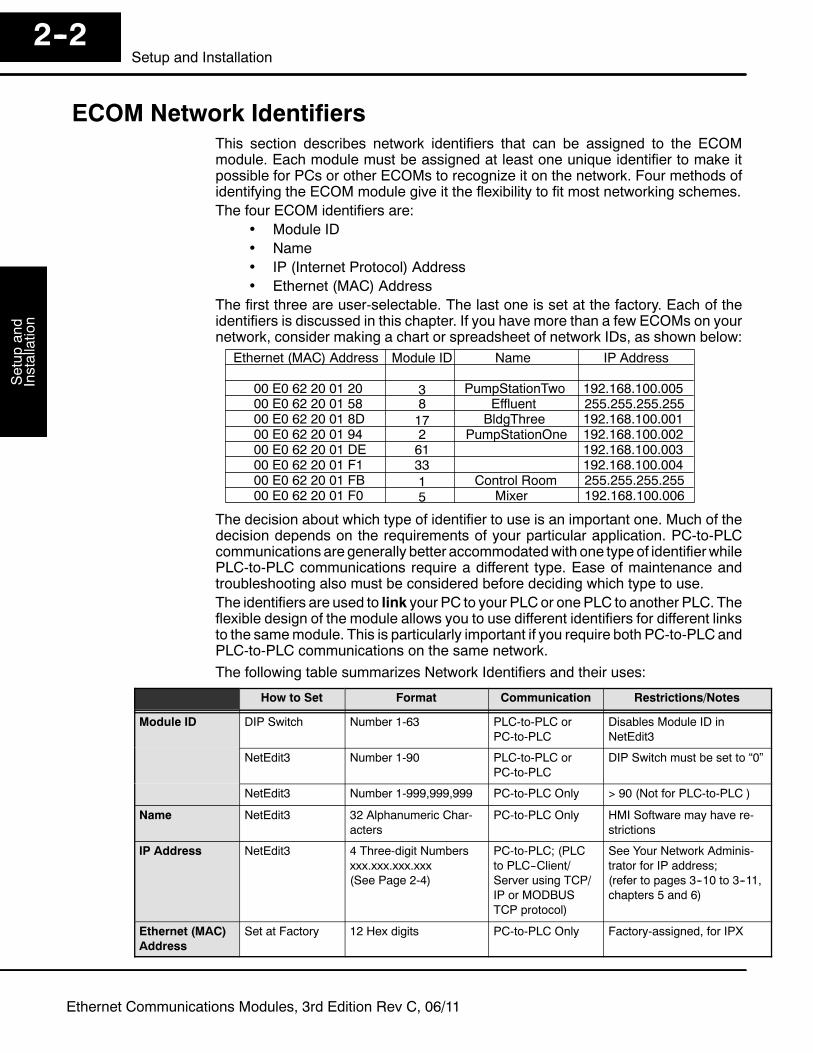
ECOM Network IdentifiersThis section describes network identifiers that can be assigned to the ECOMmodule. Each module must be assigned at least one unique identifier to make itpossible for PCs or other ECOMs to recognize it on the network. Four methods ofidentifying the ECOM module give it the flexibility to fit most networking schemes.The four ECOM identifiers are:
• Module ID• Name• IP (Internet Protocol) Address• Ethernet (MAC) Address
The first three are user-selectable. The last one is set at the factory. Each of theidentifiers is discussed in this chapter. If you have more than a few ECOMs on yournetwork, consider making a chart or spreadsheet of network IDs, as shown below:
Ethernet (MAC) Address Module ID Name IP Address
PumpStationTwoEffluentBldgThree
PumpStationOne
Control RoomMixer
192.168.100.005
192.168.100.001192.168.100.002192.168.100.003192.168.100.004
192.168.100.006
255.255.255.255
255.255.255.255
38172613315
00 E0 62 20 01 2000 E0 62 20 01 5800 E0 62 20 01 8D00 E0 62 20 01 9400 E0 62 20 01 DE00 E0 62 20 01 F100 E0 62 20 01 FB00 E0 62 20 01 F0
The decision about which type of identifier to use is an important one. Much of thedecision depends on the requirements of your particular application. PC-to-PLCcommunications are generally better accommodatedwith one type of identifierwhilePLC-to-PLC communications require a different type. Ease of maintenance andtroubleshooting also must be considered before deciding which type to use.The identifiers are used to link your PC to your PLC or onePLC to another PLC. Theflexible design of the module allows you to use different identifiers for different linksto the samemodule. This is particularly important if you require both PC-to-PLC andPLC-to-PLC communications on the same network.The following table summarizes Network Identifiers and their uses:
How to Set Format Communication Restrictions/Notes
Module ID DIP Switch Number 1-63 PLC-to-PLC orPC-to-PLC
Disables Module ID inNetEdit3
NetEdit3 Number 1-90 PLC-to-PLC orPC-to-PLC
DIP Switch must be set to “0”
NetEdit3 Number 1-999,999,999 PC-to-PLC Only > 90 (Not for PLC-to-PLC )
Name NetEdit3 32 Alphanumeric Char-acters
PC-to-PLC Only HMI Software may have re-strictions
IP Address NetEdit3 4 Three-digit Numbersxxx.xxx.xxx.xxx(See Page 2-4)
PC-to-PLC; (PLCto PLC--Client/Server using TCP/IP or MODBUSTCP protocol)
See Your Network Adminis-trator for IP address;(refer to pages 3--10 to 3--11,chapters 5 and 6)
Ethernet (MAC)Address
Set at Factory 12 Hex digits PC-to-PLC Only Factory-assigned, for IPX

Setup
andInstallation
Installationand
Safety
Guidelines2--3
Setup and Installation
Ethernet Communications Modules, 3rd Edition Rev C, 06/11
A Module ID is required for PLC-to-PLC communications, and it can be set either oftwo ways. You can assign the Module ID:
• using the DIP switches on the module.
• using the configuration tools in NetEdit3• HTML Configuration (after IP address is assigned to module using
NetEdit3; described in Chapter 5; H0/H2/H4--ECOM100 only)
Use theDIP switch if youwant the ability to install or changemoduleswithout using aPC to set theModule ID. Set themodule’s DIP switch, insert the module in the base,and connect the network cable. Your Module ID is set on powerup, and your ECOMis ready to communicate on the network. We step through setting the DIP switch onpages 2-5 and 2-6.
01234567
12345678
ON
If you prefer to be able to set or change all Module IDs on your network from a singlePC, use the tools in NetEdit3, discussed in chapter 3.ANamemakes it easy to recognize thePLCby its function. An example of a Name is“PumpStationOne.” TheName can be up to 32 alphanumeric characters in length. AName can be assigned using NetEdit3.
Pump Station One
ECOM
PUMP STATION ONE
PLC
NOTE:SomeHMI software productswill not accept Nameswith numbers as the firstcharacter, spaces or certain other non-alphanumeric ASCII characters. Also, yourHMI product may not accept Names longer than 16 characters. Consult your HMIproduct documentation about its naming conventions.
Module ID
Name
Setup
and
Installation
Installationand
SafetyGuidelines
2--4Setup and Installation
Ethernet Communications Modules, 3rd Edition Rev C, 06/11
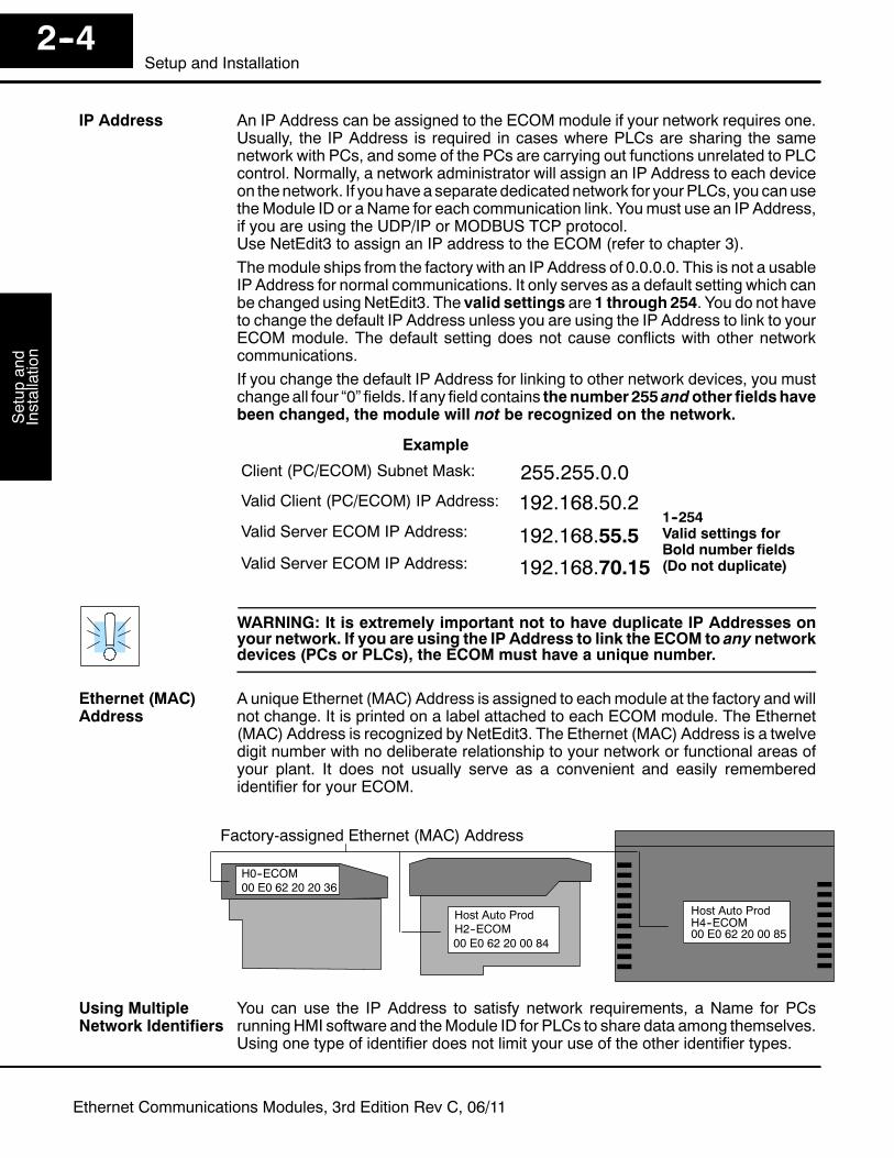
An IP Address can be assigned to the ECOM module if your network requires one.Usually, the IP Address is required in cases where PLCs are sharing the samenetwork with PCs, and some of the PCs are carrying out functions unrelated to PLCcontrol. Normally, a network administrator will assign an IP Address to each deviceon thenetwork. If youhave a separate dedicatednetwork for yourPLCs, you canusetheModule ID or a Name for each communication link. Youmust use an IP Address,if you are using the UDP/IP or MODBUS TCP protocol.Use NetEdit3 to assign an IP address to the ECOM (refer to chapter 3).Themodule ships from the factory with an IP Address of 0.0.0.0. This is not a usableIP Address for normal communications. It only serves as a default setting which canbe changed using NetEdit3. The valid settings are 1 through 254. You do not haveto change the default IP Address unless you are using the IP Address to link to yourECOM module. The default setting does not cause conflicts with other networkcommunications.If you change the default IP Address for linking to other network devices, you mustchangeall four “0” fields. If any field contains thenumber255andother fieldshavebeen changed, the module will not be recognized on the network.
Valid Client (PC/ECOM) IP Address: 192.168.50.2
Example
Valid Server ECOM IP Address: 192.168.55.5
Client (PC/ECOM) Subnet Mask: 255.255.0.0
Valid Server ECOM IP Address: 192.168.70.15
1--254Valid settings forBold number fields(Do not duplicate)
WARNING: It is extremely important not to have duplicate IP Addresses onyour network. If you are using the IP Address to link the ECOM to any networkdevices (PCs or PLCs), the ECOM must have a unique number.
A unique Ethernet (MAC) Address is assigned to eachmodule at the factory and willnot change. It is printed on a label attached to each ECOM module. The Ethernet(MAC) Address is recognized by NetEdit3. The Ethernet (MAC) Address is a twelvedigit number with no deliberate relationship to your network or functional areas ofyour plant. It does not usually serve as a convenient and easily rememberedidentifier for your ECOM.
Host Auto ProdH4--ECOM00 E0 62 20 00 85
Host Auto ProdH2--ECOM00 E0 62 20 00 84
Factory-assigned Ethernet (MAC) Address
00 E0 62 20 20 36H0--ECOM
You can use the IP Address to satisfy network requirements, a Name for PCsrunning HMI software and theModule ID for PLCs to share data among themselves.Using one type of identifier does not limit your use of the other identifier types.
IP Address
Ethernet (MAC)Address
Using MultipleNetwork Identifiers
Setup
andInstallation
Installationand
Safety
Guidelines2--5
Setup and Installation
Ethernet Communications Modules, 3rd Edition Rev C, 06/11
Setting the Module ID with the DIP Switch
You can use the DIP switch on the ECOM module to set the Module ID to anumber from one to sixty-three. Each module on a given network must beassigned a unique Module ID if the Module ID is to be used for communications.Do not use Module ID “0” for communications.If theDIPswitch is set to anumber greater than0, the software tools aredisabledfrom setting the Module ID. The software tools will only allow changes to theModule ID if the DIP switch setting is 0 (zero, all switches OFF). The DIP switchsettings are read at powerup. You can use the software tools to set the Name and IPAddress even if you use the DIP switch for setting the Module ID.
WARNING: Using duplicate Module IDs on a single network will causeunreliable PLC-to-PLC communications.
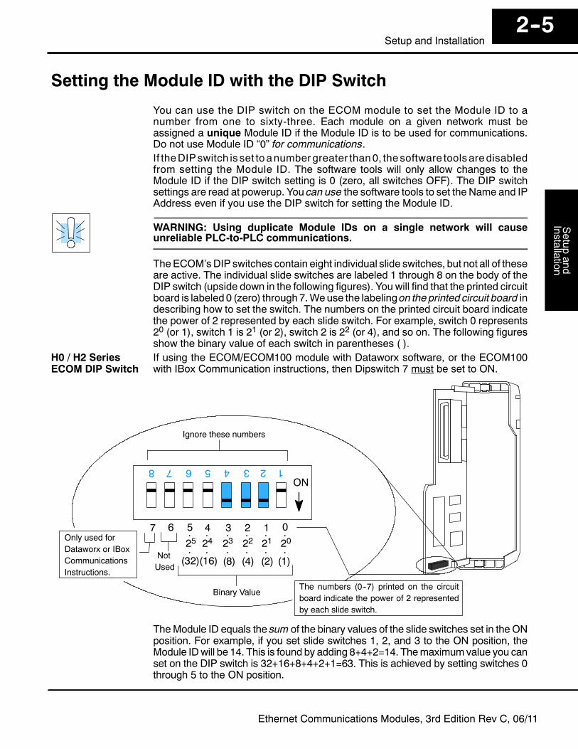
TheECOM’sDIP switches contain eight individual slide switches, but not all of theseare active. The individual slide switches are labeled 1 through 8 on the body of theDIP switch (upside down in the following figures). You will find that the printed circuitboard is labeled 0 (zero) through7.Weuse the labeling on the printed circuit board indescribing how to set the switch. The numbers on the printed circuit board indicatethe power of 2 represented by each slide switch. For example, switch 0 represents20 (or 1), switch 1 is 21 (or 2), switch 2 is 22 (or 4), and so on. The following figuresshow the binary value of each switch in parentheses ( ).If using the ECOM/ECOM100 module with Dataworx software, or the ECOM100with IBox Communication instructions, then Dipswitch 7 must be set to ON.
ON
0
1345678
1234567
(32)(16) (8) (4) (2) (1)
2
Binary Value
Ignore these numbers
202122232425.... . .
.... . .NotUsed
The numbers (0--7) printed on the circuitboard indicate the power of 2 representedby each slide switch.
Only used forDataworx or IBoxCommunicationsInstructions.
TheModule ID equals the sum of the binary values of the slide switches set in the ONposition. For example, if you set slide switches 1, 2, and 3 to the ON position, theModule IDwill be 14. This is found by adding 8+4+2=14. Themaximumvalue you canset on the DIP switch is 32+16+8+4+2+1=63. This is achieved by setting switches 0through 5 to the ON position.
H0 / H2 SeriesECOM DIP Switch
Setup
and
Installation
Installationand
SafetyGuidelines
2--6Setup and Installation
Ethernet Communications Modules, 3rd Edition Rev C, 06/11
ON
0
13
45
67
8
12
34
56
7
(32)(16) (8) (4) (2) (1)
2
Binary Value
Ignore these numbers
The numbers (0--7) printed on thecircuit board indicate the power of2 represented by each slide switch.
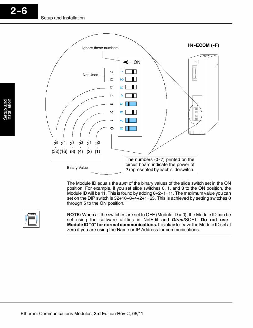
H4--ECOM (--F)
202122232425.... . .
.... . .
Not Used
The Module ID equals the sum of the binary values of the slide switch set in the ONposition. For example, if you set slide switches 0, 1, and 3 to the ON position, theModule IDwill be 11. This is found by adding 8+2+1=11. Themaximum value you canset on the DIP switch is 32+16+8+4+2+1=63. This is achieved by setting switches 0through 5 to the ON position.
NOTE:When all the switches are set to OFF (Module ID = 0), the Module ID can beset using the software utilities in NetEdit and DirectSOFT. Do not useModule ID “0” for normal communications. It is okay to leave theModule ID set atzero if you are using the Name or IP Address for communications.
Setup
andInstallation
Installationand
Safety
Guidelines2--7
Setup and Installation
Ethernet Communications Modules, 3rd Edition Rev C, 06/11
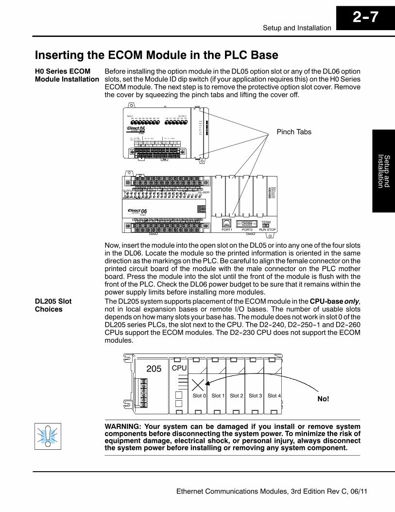
Inserting the ECOM Module in the PLC BaseBefore installing the option module in the DL05 option slot or any of the DL06 optionslots, set theModule ID dip switch (if your application requires this) on the H0SeriesECOMmodule. The next step is to remove the protective option slot cover. Removethe cover by squeezing the pinch tabs and lifting the cover off.
Pinch Tabs
C0 C4C2X1 X3 X4 X6 X11X13X14 X16 X21 X23N.C.C1 C3X2 X5 X7 X10X12 X15X17X20X22X0 N.C.
AC(N) 24V0V
N.C.C1 C3Y0 Y15Y12Y10 Y17Y7Y5Y2
C0 C2 Y16Y14Y13Y11Y6Y4Y3Y1LGG
AC(L)2.0AOUTPUT: 6--240V50 -- 60Hz2.0A,6 -- 27V
INPUT: 12 -- 24V3 -- 15mA
YX
40VA50--60HzPWR: 100--240V0 1 2 3 4 5 6 7 10 11 12 13 14 15 16 17 20 21 22 23
PORT1 RUN STOP
PWRRUNCPUTX1RX1TX2RX2
D0--06DR
PORT2
TERM
Now, insert themodule into the open slot on theDL05 or into any one of the four slotsin the DL06. Locate the module so the printed information is oriented in the samedirection as themarkings on thePLC. Be careful to align the female connector on theprinted circuit board of the module with the male connector on the PLC motherboard. Press the module into the slot until the front of the module is flush with thefront of the PLC. Check the DL06 power budget to be sure that it remains within thepower supply limits before installing more modules.TheDL205 systemsupports placement of the ECOMmodule in theCPU-baseonly,not in local expansion bases or remote I/O bases. The number of usable slotsdepends on howmany slots your base has. Themodule does not work in slot 0 of theDL205 series PLCs, the slot next to the CPU. The D2--240, D2--250--1 and D2--260CPUs support the ECOM modules. The D2--230 CPU does not support the ECOMmodules.
Slot 0 Slot 1 Slot 2 Slot 3 Slot 4
205 CPU
No!
WARNING: Your system can be damaged if you install or remove systemcomponents before disconnecting the system power. To minimize the risk ofequipment damage, electrical shock, or personal injury, always disconnectthe system power before installing or removing any system component.
H0 Series ECOMModule Installation
DL205 SlotChoices
Setup
and
Installation
Installationand
SafetyGuidelines
2--8Setup and Installation
Ethernet Communications Modules, 3rd Edition Rev C, 06/11
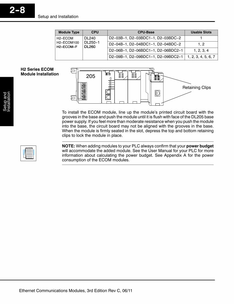
Module Type CPU CPU-Base Usable Slots
H2--ECOMH2 ECOM100
DL240DL250 1
D2--03B--1, D2--03BDC1--1, D2--03BDC--2 1H2--ECOM100H2--ECOM--F
DL250--1DL260
D2--04B--1, D2--04BDC1--1, D2--04BDC--2 1, 2H2--ECOM--F DL260
D2--06B--1, D2--06BDC1--1, D2--06BDC2--1 1, 2, 3, 4
D2--09B--1, D2--09BDC1--1, D2--09BDC2--1 1, 2, 3, 4, 5, 6, 7
Retaining Clips
205
To install the ECOM module, line up the module’s printed circuit board with thegrooves in the base and push themodule until it is flush with face of the DL205 basepower supply. If you feel more thanmoderate resistance when you push themoduleinto the base, the circuit board may not be aligned with the grooves in the base.When the module is firmly seated in the slot, depress the top and bottom retainingclips to lock the module in place.
NOTE:When adding modules to your PLC always confirm that your power budgetwill accommodate the added module. See the User Manual for your PLC for moreinformation about calculating the power budget. See Appendix A for the powerconsumption of the ECOM modules.
H2 Series ECOMModule Installation
Setup
andInstallation
Installationand
Safety
Guidelines2--9
Setup and Installation
Ethernet Communications Modules, 3rd Edition Rev C, 06/11
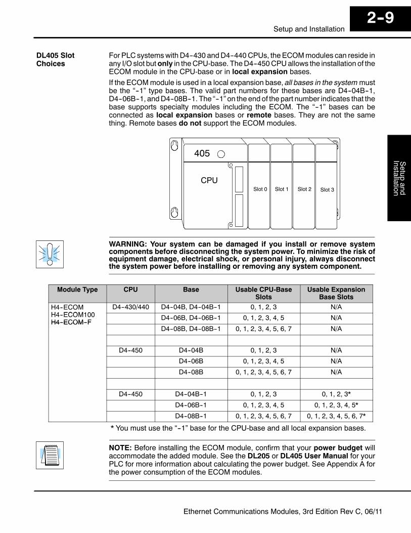
For PLC systemswithD4--430 andD4--440CPUs, the ECOMmodules can reside inany I/O slot butonly in theCPU-base. TheD4--450CPUallows the installation of theECOM module in the CPU-base or in local expansion bases.If the ECOMmodule is used in a local expansion base, all bases in the systemmustbe the “--1” type bases. The valid part numbers for these bases are D4--04B--1,D4--06B--1, andD4--08B--1. The “--1” on the endof the part number indicates that thebase supports specialty modules including the ECOM. The “--1” bases can beconnected as local expansion bases or remote bases. They are not the samething. Remote bases do not support the ECOM modules.
405
Slot 0 Slot 1 Slot 2 Slot 3
CPU
WARNING: Your system can be damaged if you install or remove systemcomponents before disconnecting the system power. To minimize the risk ofequipment damage, electrical shock, or personal injury, always disconnectthe system power before installing or removing any system component.
Module Type CPU Base Usable CPU-BaseSlots
Usable ExpansionBase Slots
H4--ECOMH4 ECOM100
D4--430/440 D4--04B, D4--04B--1 0, 1, 2, 3 N/AH4--ECOM100H4--ECOM--F
D4--06B, D4--06B--1 0, 1, 2, 3, 4, 5 N/AH4--ECOM--F
D4--08B, D4--08B--1 0, 1, 2, 3, 4, 5, 6, 7 N/A
D4--450 D4--04B 0, 1, 2, 3 N/A
D4--06B 0, 1, 2, 3, 4, 5 N/A
D4--08B 0, 1, 2, 3, 4, 5, 6, 7 N/A
D4--450 D4--04B--1 0, 1, 2, 3 0, 1, 2, 3*
D4--06B--1 0, 1, 2, 3, 4, 5 0, 1, 2, 3, 4, 5*
D4--08B--1 0, 1, 2, 3, 4, 5, 6, 7 0, 1, 2, 3, 4, 5, 6, 7*
* You must use the “--1” base for the CPU-base and all local expansion bases.
NOTE: Before installing the ECOM module, confirm that your power budget willaccommodate the added module. See the DL205 or DL405 User Manual for yourPLC for more information about calculating the power budget. See Appendix A forthe power consumption of the ECOM modules.
DL405 SlotChoices
Setup
and
Installation
Installationand
SafetyGuidelines
2--10Setup and Installation
Ethernet Communications Modules, 3rd Edition Rev C, 06/11
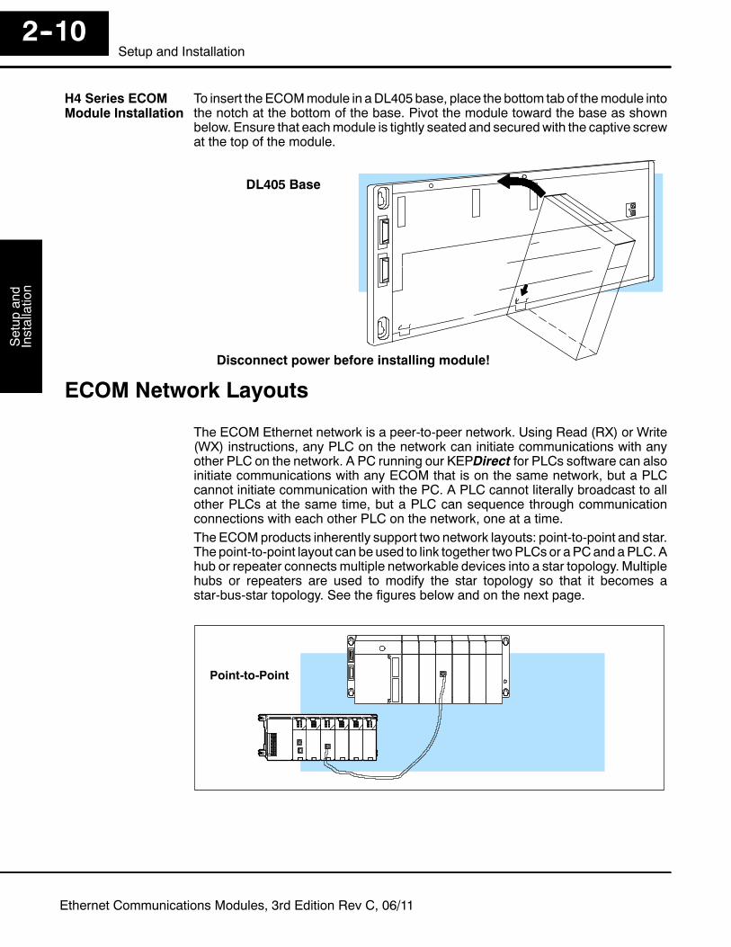
To insert the ECOMmodule in aDL405 base, place the bottom tab of themodule intothe notch at the bottom of the base. Pivot the module toward the base as shownbelow. Ensure that eachmodule is tightly seated and securedwith the captive screwat the top of the module.
DL405 Base
Disconnect power before installing module!
ECOM Network Layouts
The ECOM Ethernet network is a peer-to-peer network. Using Read (RX) or Write(WX) instructions, any PLC on the network can initiate communications with anyother PLC on the network. A PC running our KEPDirect for PLCs software can alsoinitiate communications with any ECOM that is on the same network, but a PLCcannot initiate communication with the PC. A PLC cannot literally broadcast to allother PLCs at the same time, but a PLC can sequence through communicationconnections with each other PLC on the network, one at a time.The ECOMproducts inherently support two network layouts: point-to-point and star.The point-to-point layout can be used to link together twoPLCs or aPCand aPLC. Ahub or repeater connects multiple networkable devices into a star topology. Multiplehubs or repeaters are used to modify the star topology so that it becomes astar-bus-star topology. See the figures below and on the next page.
Point-to-Point
H4 Series ECOMModule Installation

Setup
andInstallation
Installationand
Safety
Guidelines2--11
Setup and Installation
Ethernet Communications Modules, 3rd Edition Rev C, 06/11
Star Topology
Hub or Repeater10/100BaseT
or10BaseFL
Hubs or repeaters can connect together tomake it possible to connectmore devicesto the network or to extend the range of the network.
Star-Bus-Star Topology
Hub or Repeater
10Base210Base5
10BaseTor
10BaseFL
Any Backbone
10BaseT
10BaseFL100BaseT
NOTE: Hubs or repeaters often designate one port for uplink to another hub. Thisport may not be able to be used to connect to a PLC. If the uplink port is used toconnect to another hub, it may disable the adjacent port. Use of the uplink port mayrequire the use of a crossover cable.
Setup
and
Installation
Installationand
SafetyGuidelines
2--12Setup and Installation
Ethernet Communications Modules, 3rd Edition Rev C, 06/11
Network Cabling
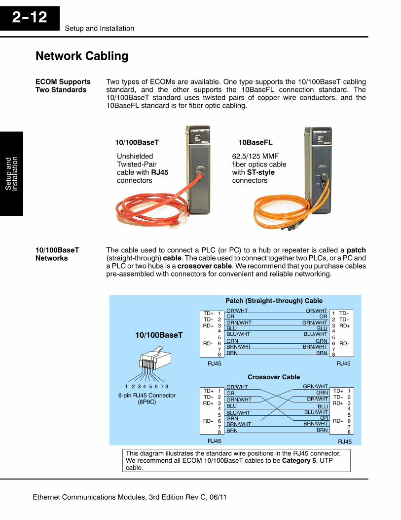
Two types of ECOMs are available. One type supports the 10/100BaseT cablingstandard, and the other supports the 10BaseFL connection standard. The10/100BaseT standard uses twisted pairs of copper wire conductors, and the10BaseFL standard is for fiber optic cabling.
10/100BaseT 10BaseFL
UnshieldedTwisted-Paircable with RJ45connectors
62.5/125 MMFfiber optics cablewith ST-styleconnectors
The cable used to connect a PLC (or PC) to a hub or repeater is called a patch(straight-through) cable. The cable used to connect together two PLCs, or a PC anda PLC or two hubs is a crossover cable. We recommend that you purchase cablespre-assembled with connectors for convenient and reliable networking.
Patch (Straight--through) Cable
Crossover Cable
This diagram illustrates the standard wire positions in the RJ45 connector.We recommend all ECOM 10/100BaseT cables to be Category 5, UTPcable.
2 TD--1 TD+
3 RD+456 RD--78
3 4 5 621 87
8-pin RJ45 Connector(8P8C)
RJ45 RJ45
RJ45 RJ45
TD-- 2TD+ 1
RD+ 345
RD-- 678
GRN
GRN/WHT
OR/WHTOR
BLUBLU/WHT
BRN/WHTBRN
GRN
GRN/WHT
OR/WHTOR
BLUBLU/WHT
BRN/WHTBRN
TD-- 2TD+ 1
RD+ 345
RD-- 678
TD-- 2TD+ 1
RD+ 345
RD-- 678
GRN
GRN/WHT
OR/WHTOR
BLUBLU/WHT
BRN/WHTBRN
GRNGRN/WHT
OR/WHT
OR
BLUBLU/WHT
BRN/WHTBRN
10/100BaseT
ECOM SupportsTwo Standards
10/100BaseTNetworks
Setup
andInstallation
Installationand
Safety
Guidelines2--13
Setup and Installation
Ethernet Communications Modules, 3rd Edition Rev C, 06/11
Most 10/100BaseT hubs or repeaters use a patch (straight-through) cable forconnecting the network devices (PLCs or PCs). For hub-to-hub connections acrossover type cable is commonly required. The figures on the previous page showpin assignments and insulation color codes for patch (straight-through) andcrossover type Ethernet cables.The ECOM has an eight-pin modular port that accepts RJ45 type connectors. UTP(Unshielded Twisted-Pair) cable is rated according to its data-carrying ability(bandwidth) and is given a “category” number. We strongly recommend using acategory 5 cable for all ECOM connections.
NOTE: See page 2--14 for 10/100BaseT distance limitations.
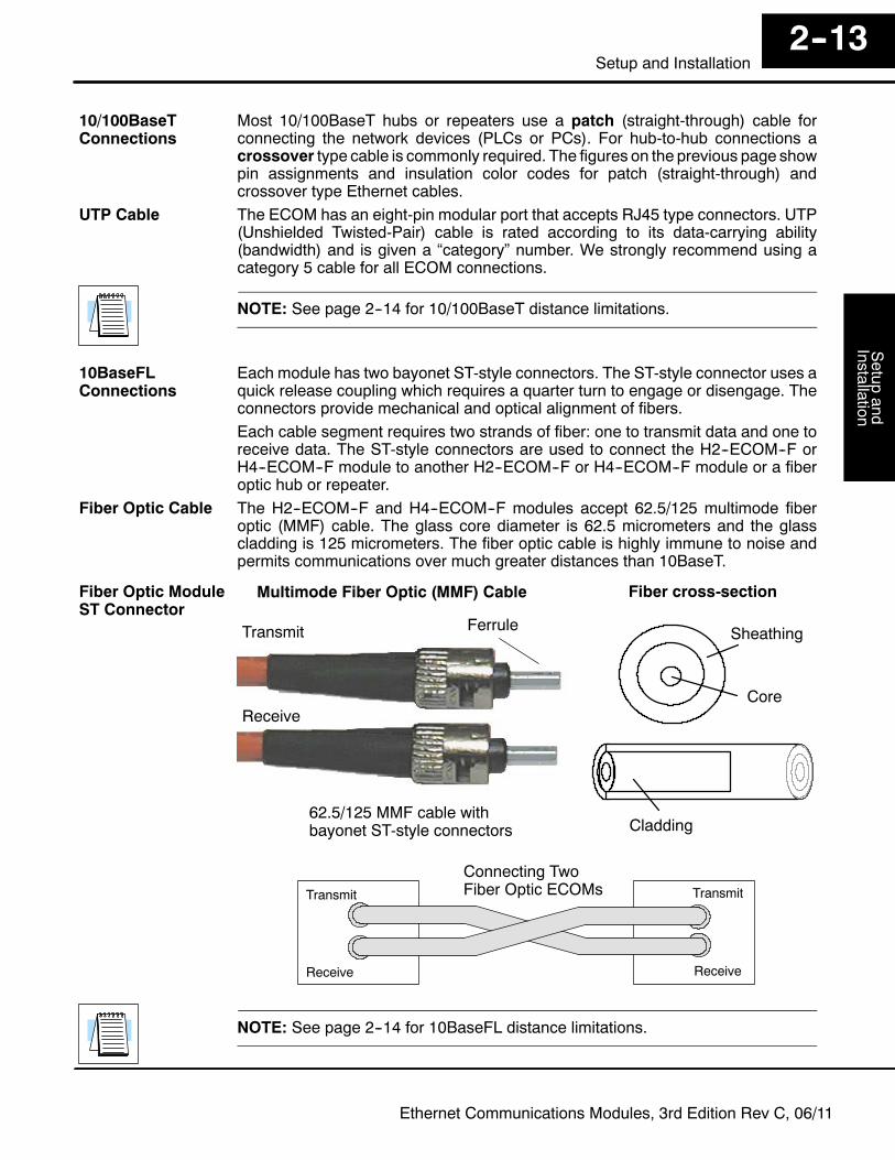
Each module has two bayonet ST-style connectors. The ST-style connector uses aquick release coupling which requires a quarter turn to engage or disengage. Theconnectors provide mechanical and optical alignment of fibers.Each cable segment requires two strands of fiber: one to transmit data and one toreceive data. The ST-style connectors are used to connect the H2--ECOM--F orH4--ECOM--F module to another H2--ECOM--F or H4--ECOM--F module or a fiberoptic hub or repeater.The H2--ECOM--F and H4--ECOM--F modules accept 62.5/125 multimode fiberoptic (MMF) cable. The glass core diameter is 62.5 micrometers and the glasscladding is 125 micrometers. The fiber optic cable is highly immune to noise andpermits communications over much greater distances than 10BaseT.
Transmit
Receive
Multimode Fiber Optic (MMF) Cable
Ferrule
62.5/125 MMF cable withbayonet ST-style connectors
Core
Cladding
Fiber cross-section
Sheathing
Transmit Transmit
Receive Receive
Connecting TwoFiber Optic ECOMs
NOTE: See page 2--14 for 10BaseFL distance limitations.
10/100BaseTConnections
UTP Cable
10BaseFLConnections
Fiber Optic Cable
Fiber Optic ModuleST Connector

Setup
and
Installation
Installationand
SafetyGuidelines
2--14Setup and Installation
Ethernet Communications Modules, 3rd Edition Rev C, 06/11
Maximum Cable Length
Themaximum distance per 10/100BaseT cable segment is 100meters or 328 feet.Repeaters extend the distance. Each cable segment attached to a repeater can be 100meters. Two repeaters connected together extend the total range to 300 meters.
100 meters(328 feet)100 meters
(328 feet)
100 meters(328 feet)
100 meters(328 feet)
100 meters(328 feet)
RepeatersBetween
10/100BaseT Distance Limitations
Themaximumdistance per 10BaseFL cable segment is 2,000meters or 6,560 feet.Repeaters extend the distance. Each cable segment attached to a repeater can be 2,000meters. Two repeaters connected together extend the total range to 6,000 meters.
2,000 meters
RepeatersBetween
10BaseFL Distance Limitations
2,000 meters
2,000 meters(6,560 feet)2,000 meters
2,000 meters
(6,560 feet)
(6,560 feet)(6,560 feet)
(6,560 feet)

Setup
andInstallation
Installationand
Safety
Guidelines2--15
Setup and Installation
Ethernet Communications Modules, 3rd Edition Rev C, 06/11
Maximum Number of ECOM Modules on the Network
The maximum number of nodes that can be connected to a 10/100BaseT or10BaseFL network is a function of the topology used in constructing the network.Therefore, it is not possible to state an absolute maximum number of nodes thatwould apply in all cases.
The IEEE 802.3 specification defines the maximum node limit for an Ethernetsegment in terms of the ability to detect and avoid data collisions. A “legal” networkcan have any number of devices provided that they can:
• detect all data collisions that may occur during the communicationprocess and
• respond to these collisions appropriately.
You must take into consideration the network limitations imposed by all cabling andnetwork devices. Consider the limitations imposed on your network if your networkuses:
• a combination of cabling standards, such as 10/100 BaseT and10Base2, or
• intermediate devices, such as switches or routers.
Each ECOM module can be assigned a Module ID ranging from 1 to 999,999,999.Theoretically, you could have this many Ethernet modules coexisting on a singlenetwork. Other network limitations would restrict the network size before reachingthis limit. For the majority of network PLC applications there is practically no limit tothe number of ECOM modules you can access from the NetEdit3, DirectSOFTProgramming Software or the KEPDirect for PLCs software.
There is a node limit for PLC-to-PLC communications. The network Read andWriteinstructions performed by the initiating (master) PLC are only capable of accessingPLCs with Module IDs of 1 through 90. This effectively sets themaximum number ofnodes available for PLC-to-PLC communications at 90.
WARNING:We recommend against connecting Ethernetmodules to the samenetwork that serves as your primary office network. While Ethernet networkscan handle a very large number of data transmissions, and normally handlethem very quickly, heavy Ethernet traffic can adversely affect the reliabilityand speed of the network.