sew eurodrive movidrive - efes otomasyon · sew eurodrive movidrive this manual presents...
TRANSCRIPT

SEW Eurodrive MOVIDRIVEThis manual presents installation and handling of the driver SEW Euro-drive MOVIDRIVE to the terminals in the Cimrex series.
The functionality in the Cimrex terminals and in CIMREX PROG are des-cribed in the Cimrex manual.
© Cimrex Electronics AB 2000, MA00497, 2000-09
Cimrex Electronics AB reserves the right to change information in this manual without prior notice. All examples in this manual are used solely to promote understanding of how the program works and its operation. Cimrex Electronics AB take no responsibility if these examples are used in real applications.

Content
2
Content
1 Introduction ...........................................................................................3
2 Install and update driver .......................................................................4
2.1 Installation of driver using Internet..................................................42.2 Installation of driver from disk.........................................................4
3 Connecting the terminal to the drive inverter.............................................................................................5
3.1 Settings in the CIMREX PROG .........................................................5
3.2 Settings in the drive inverter ............................................................8
3.3 Connecting the terminal to the drive inverter ..................................9
4 Addressing ...........................................................................................11
4.1 Station handling..............................................................................12
5 Efficient communication .....................................................................13
5.1 Signals affecting the communication time......................................13
5.2 How to make the communication more efficient ...........................14
5.3 Trouble shooting schedule..............................................................15
6 Drawings ..............................................................................................16

Introduction
3
1 Introduction
This manual describes how the drive inverter SEW Eurodrive MOVID-RIVE is connected to the operator terminals in the Cimrex series via the protocol MOVILINK and how they communicate. Addressing of an item is done in the normal SEW Eurodrive MOVILINK way. For information about the drive inverter we refer to the manual for current inverter.
The driver can be used with the SEW Eurodrive MOVIDRIVE series drive inverters.

Install and update driver
4
2 Install and update driver
When installing CIMREX PROG the drivers available at the time of release are installed too. A new driver can be added into CIMREX PROG either with CIMREX PROG using an Internet connection or from diskette. A driver can be updated to a newer version in the same ways.
2.1 Installation of driver using InternetTo update available drivers to the latest version or to install new drivers you can use the function Update terminal drivers, from Internet in the File menu in CIMREX PROG. All projects must be closed before this function is used and the computer must be able to make an Internet connection. You don't need a browser. When the connection is established a list is shown with all drivers that can be downloaded from Internet to the com-puter. The list shows the version number of available drivers and the ver-sion number of installed drivers. Mark the driver/drivers you want to install in the CIMREX PROG. The function Mark Newer will mark all drivers that are available in a newer version then the one installed and the drivers not installed. Then you select Download. Each drivers is approxi-mately 500 kb and it is ready to use when the download is ready.
2.2 Installation of driver from diskTo update available drivers to the latest version or to install new drivers you can use the function Update terminal drivers, from Disk in the File menu in CIMREX PROG. All projects must be closed before this function is used. Select the folder with the new driver and choose to open the mpd-file. A list is shown with all drivers that can be installed showing the ver-sion number of available drivers and the version number of installed driv-ers. Mark the driver/drivers you want to install in the CIMREX PROG. The function Mark Newer will mark all drivers that are available in a new-er version then the one installed and the drivers not installed. Then you select Install.
How to select the SEW Eurodrive MOVIDRIVE driver in the project and how to transfer it to the terminal are described in chapter 3.

Connecting the terminal to the drive inverter
5
3 Connecting the terminal to the drive inverter
3.1 Settings in the CIMREX PROGFor communication with the drive inverter via the protocol MOVILINK the following settings must be made in the programming tool CIMREX PROG.
Driver selectionChoosing New in the File menu creates a new project and the dialog Project Settings is shown. In an existing project, the dialog is shown by selecting Project Settings in the File menu.
Press Change… under Controller system to get the choice list of available drivers. Choose Brand name, Protocol and then press OK. Press OK again to confirm the project settings.

Connecting the terminal to the drive inverter
6
Communication setupThe settings for the communication between the terminal and the drive in-verter are done under Peripherals in the Setup menu. To change which port the drive inverter is connected to, mark Controller and hold left mouse button down and drag to move it to another communication port. Mark the selected communication port and press Edit to change the other communication settings.
The settings should be:
Parameter Description
Port RS-232 or RS-422
Baudrate 9600
Data bits 8
Stop bits 1
Parity Even

Connecting the terminal to the drive inverter
7
To make specific settings for the selected driver mark the driver name and press Edit.
Under Settings you define the default station number. Values 0-99, 254 and 255 can be stated. 0-99 are individual addresses to inverters while 254 is an general address for point-to-point communication. Address 254 can not be used if there are more than one inverter connected to the network because any inverter will reply to this address irrespectively of it’s own address. Address 255 is an broadcast address which all inverters are lis-tening to and they will not reply to this message.
Error messagesWrong parameterNo access to P844 Parameter does not exist.
Communication faultsComm Error 10.11.0.0 Error class.Error code.Address code high.Address
code low

Connecting the terminal to the drive inverter
8
Transfer the driver to the terminalThe selected driver is downloaded into the terminal when the project is transferred to the terminal. Choose Project in the Transfer menu.
There are three alternatives when the driver is downloaded into the termi-nal:
3.2 Settings in the drive inverterFor information about settings in the drive inverter we refer to the manual for current system.
Function Description
Never The driver is not downloaded and the existing driver in the terminal is used.
Always The driver is downloaded every time the project is trans-ferred.
Automatic The driver is down-loaded if the driver in the terminal is not the same as the selected driver in the project. If it is the same the driver is not downloaded.

Connecting the terminal to the drive inverter
9
3.3 Connecting the terminal to the drive inverter
Point-to-point connection
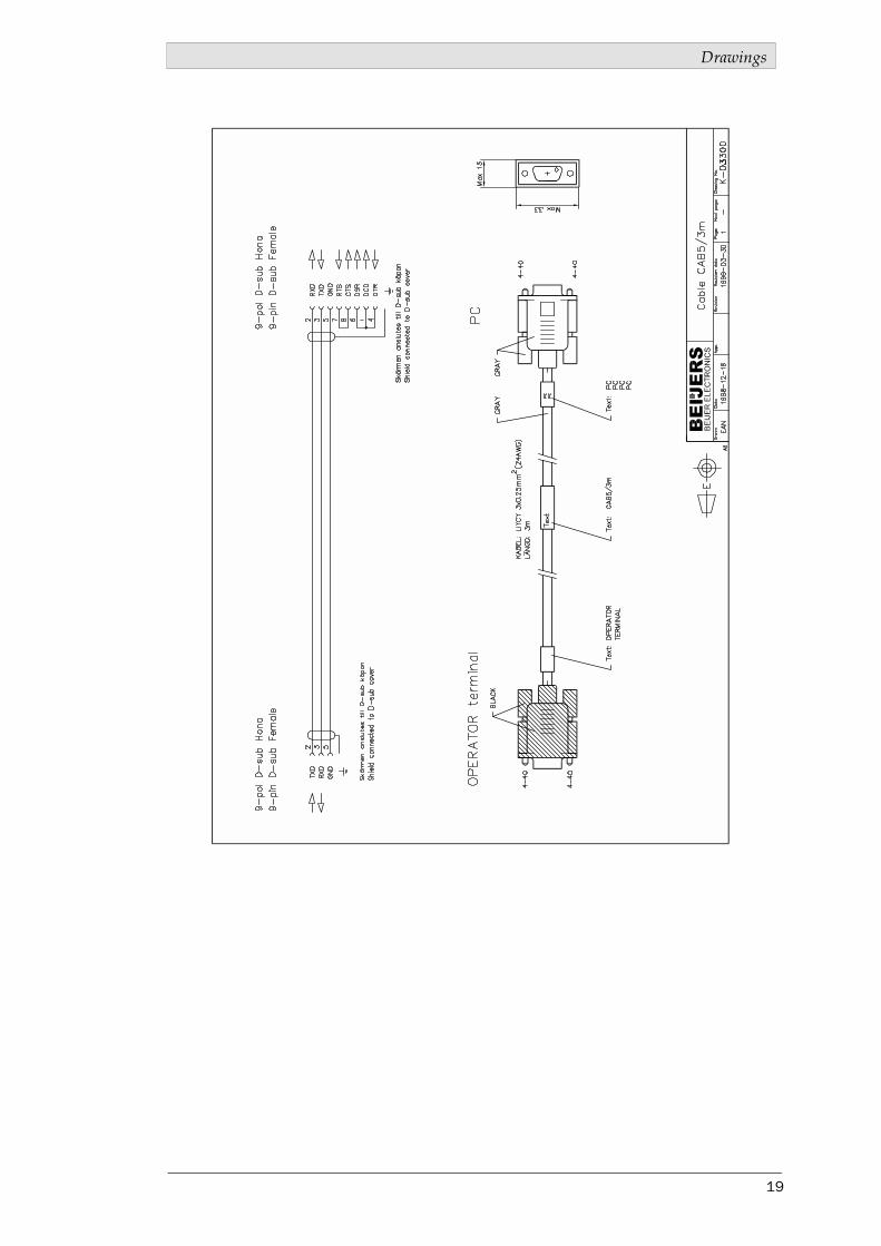
The point-to-point connection can be done via the RS-232C port on the ter-minal to the RS232 interface on the module USS21A on the SEW Eurodrive MOVIDRIVE. For cable configuration see cable drawing below.
Multidrop connection
The terminal is connected to an RS-485 network via the adaptor CAB8 which is connected to the RS-422 port on the terminal. CAB8 is a standard adaptor that can be ordered from Cimrex Electronics.
Terminal to RS485 interface on the USS21A module on MOVIDRIVE
RS-232 or RS-422
CIMREX terminal9-pin DSUB female
SEW Eurodrive MOVIDRIVE
9-pin DSUB male
325
TxD 2RxD 3GND 5
RS-232 interface on module USS21A
CAB8
RS-422
See cable drawing below
RS-485RS-485
CAB8Plint
SEW Eurodrive MOVIDRIVE
+-0V5
1 23
1234
RS-485 Plint
5678
Connecting the terminal to the drive inverter
10
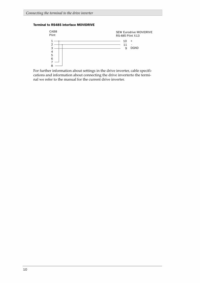
Terminal to RS485 interface MOVIDRIVE
For further information about settings in the drive inverter, cable specifi-cations and information about connecting the drive inverterto the termi-nal we refer to the manual for the current drive inverter.
CAB8Plint
SEW Eurodrive MOVIDRIVE
+-DGND
10119
1234
RS-485 Plint X13
5678
Addressing
11
4 Addressing
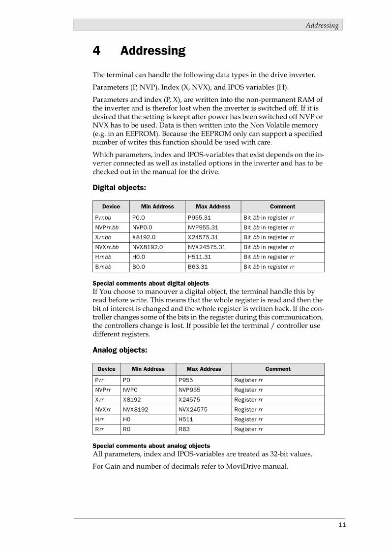
The terminal can handle the following data types in the drive inverter.
Parameters (P, NVP), Index (X, NVX), and IPOS variables (H).
Parameters and index (P, X), are written into the non-permanent RAM of the inverter and is therefor lost when the inverter is switched off. If it is desired that the setting is keept after power has been switched off NVP or NVX has to be used. Data is then written into the Non Volatile memory (e.g. in an EEPROM). Because the EEPROM only can support a specified number of writes this function should be used with care.
Which parameters, index and IPOS-variables that exist depends on the in-verter connected as well as installed options in the inverter and has to be checked out in the manual for the drive.
Digital objects:
Special comments about digital objectsIf You choose to manouver a digital object, the terminal handle this by read before write. This means that the whole register is read and then the bit of interest is changed and the whole register is written back. If the con-troller changes some of the bits in the register during this communication, the controllers change is lost. If possible let the terminal / controller use different registers.
Analog objects:
Special comments about analog objectsAll parameters, index and IPOS-variables are treated as 32-bit values.
For Gain and number of decimals refer to MoviDrive manual.
Device Min Address Max Address Comment
Prr.bb P0.0 P955.31 Bit bb in register rr
NVPrr.bb NVP0.0 NVP955.31 Bit bb in register rr
Xrr.bb X8192.0 X24575.31 Bit bb in register rr
NVXrr.bb NVX8192.0 NVX24575.31 Bit bb in register rr
Hrr.bb H0.0 H511.31 Bit bb in register rr
Brr.bb B0.0 B63.31 Bit bb in register rr
Device Min Address Max Address Comment
Prr P0 P955 Register rr
NVPrr NVP0 NVP955 Register rr
Xrr X8192 X24575 Register rr
NVXrr NVX8192 NVX24575 Register rr
Hrr H0 H511 Register rr
Rrr R0 R63 Register rr

Addressing
12
4.1 Station handlingIn the Driver Configuration dialog you state the default station. The de-fault station is the station the terminal checks communication towards at start up, and it is also the station for the device which is not assigned to any specific station. For communication with other stations the station number is given as a prefix to the device.
Example
13:P5 Parameter 5 in station 13
Efficient communication
13
5 Efficient communication
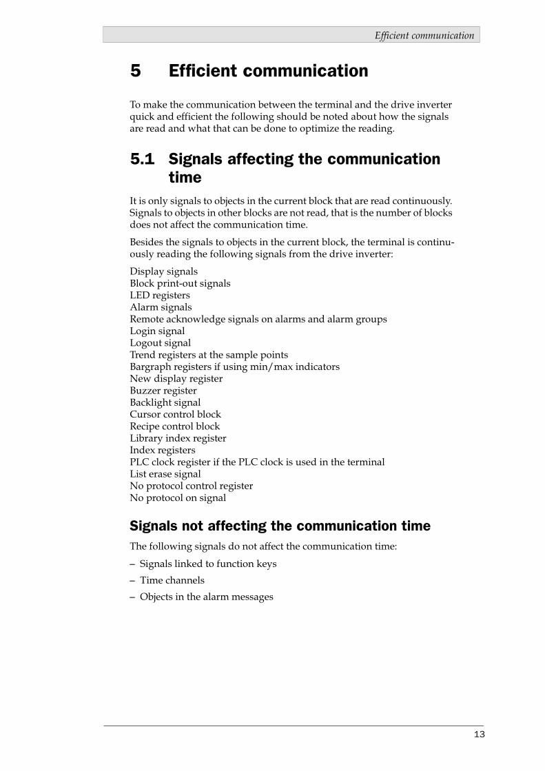
To make the communication between the terminal and the drive inverter quick and efficient the following should be noted about how the signals are read and what that can be done to optimize the reading.
5.1 Signals affecting the communication time
It is only signals to objects in the current block that are read continuously. Signals to objects in other blocks are not read, that is the number of blocks does not affect the communication time.
Besides the signals to objects in the current block, the terminal is continu-ously reading the following signals from the drive inverter:
Display signalsBlock print-out signalsLED registersAlarm signalsRemote acknowledge signals on alarms and alarm groupsLogin signalLogout signalTrend registers at the sample pointsBargraph registers if using min/max indicatorsNew display registerBuzzer registerBacklight signalCursor control blockRecipe control blockLibrary index registerIndex registersPLC clock register if the PLC clock is used in the terminalList erase signalNo protocol control registerNo protocol on signal
Signals not affecting the communication timeThe following signals do not affect the communication time:
– Signals linked to function keys
– Time channels
– Objects in the alarm messages

Efficient communication
14
5.2 How to make the communication more efficient
Group PLC-signals consecutivelyThe signals from the PLC system are read most rapidly if all signals in the list above are consecutive. If for example, 100 signals are defined, it is quickest to read these if they are linked to, for example, M0.0-M11.7. If the signals are spread out (e.g. I0.4, Q30.0, T45.3 etc.) the updating is slower.
Efficient block changesBlock changes are carried out most rapidly and efficiently through the block jump function on the function keys or through a jump object. "Dis-play signals" in the block header should only be used when the PLC sys-tem is to force the presentation of another block. The "New Display" register can also be used if the PLC system is to change the block. This does not affect communication as much as a larger number of "Display signals".
Use the clock of the terminalAn extra load is put on communication if the clock of the PLC system is used since the clock register must be read up to the terminal. Download-ing of the clock to the PLC system also creates an extra load. The interval between downloadings should therefore be as long as possible.
Packaging of signalsWhen the signals are transferred between the terminal and the PLC sys-tem, all signals are not transferred simultaneously. Instead they are divid-ed into packages with a number of signals in each package. To decrease the number of packages that have to be transferred and make the commu-nication faster this number has to be considered. The number of signals in each package depends on the used driver. In the SEW Eurodrive MOVID-RIVE driver the number is 1 for analog devices and 32 for digital devices.
To make the communication as fast as possible the number of packages has to be minimized. Consecutive signals require a minimum of used packages but it is not always possible to have consecutive signals. In such cases the so-called waste between two signals has to be considered. The waste is the maximum distance between two signals you can have and still keep them in the same package.
The waste depends on the driver used. In the SEW Eurodrive MOVID-RIVE driver the number is 30 for digital devices. Analog devices don not cause any waste.
Signal
Used X X X X X1 2 3 4 5 6 7 8 9 10
Waste
Efficient communication
15
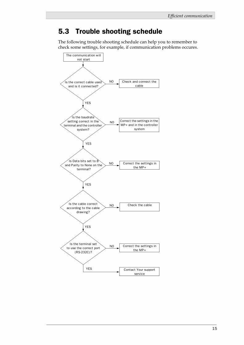
5.3 Trouble shooting scheduleThe following trouble shooting schedule can help you to remember to check some settings, for example, if communication problems occures.
Is the baudrate setting correct in the
terminal and the controller system?
The communication will not start
Is the correct cable used and is it connected?
Is Data bits set to 8 and Parity to None on the
terminal?
Is the cable correct according to the cable
drawing?
Is the terminal set to use the correct port
(RS-232C)?
Check and connect the cable
Correct the settings in the MP+ and in the controller
system
Correct the settings in the MP+
Check the cable
Correct the settings in the MP+
Contact Your support service
YES
YES
YES
YES
YES
NO
NO
NO
NO
NO

Drawings
16
6 Drawings

Drawings
17

Drawings
18
Drawings
19