sewerage system standard practice manual hydraulic loading rates ... table d-1: method 3 —...
TRANSCRIPT

SEWERAGE SYSTEM STANDARD PRACTICE MANUAL
September, 2006
Issued By:
Ministry of Health Population Health and Wellness Health Protection 4th Floor, 1515 Blanshard Street Victoria, BC V8W 3C8

This page is intentionally blank.

Table of Contents 1 Purpose and Content of this Manual .........................................................................5
1.1 Purpose..............................................................................................................................5 1.2 Content ..............................................................................................................................6
2 Administrative..............................................................................................................6 2.1 Administrative Process......................................................................................................6 2.2 Filing Cancellation ............................................................................................................7 2.3 Filing Notification Referrals .............................................................................................7 2.4 Privacy...............................................................................................................................7 2.5 Other Administrative Jurisdictions....................................................................................7 2.6 Restrictive Covenants........................................................................................................7 2.7 Use of Adjacent Property ..................................................................................................8 2.8 Easements and Covenants .................................................................................................8 2.9 New Systems.....................................................................................................................8 2.10 Repairs and Replacements ................................................................................................8
2.10.1 Component Repair or Replacement .....................................................................8 2.10.2 System Repair or Replacement ............................................................................9
2.11 Seasonal Dwellings with No Hydro Connection...............................................................9 2.12 Multiple Homes on Same Property .................................................................................10
3 Roles and Responsibilities .........................................................................................10 3.1 Health Authority..............................................................................................................10 3.2 Authorized Person...........................................................................................................10 3.3 Sewerage System Owner.................................................................................................11
4 Wastewater Flow Rates .............................................................................................11 4.1 Design Flows...................................................................................................................11 4.2 Minimum Design Flow Rates for Residences.................................................................12
4.2.1 Flow Reduction Devices ....................................................................................12 4.3 Garbage Grinders (Garburators)......................................................................................12
4.3.1 Treatment ...........................................................................................................12 4.3.2 Distribution ........................................................................................................12
4.4 Other Minimum Design Flow Rates ...............................................................................12 4.4.1 Design Non-Residential Waste Design Flows ...................................................13
5 Determination of Treatment and Disposal Requirements .....................................19 5.1 Process Selection.............................................................................................................19 5.2 Levels of Treatment ........................................................................................................19 5.3 Site Constraints for Sewage Treatment Selection ...........................................................19 5.4 Selecting a Treatment System Based on Site Constraint (SC)........................................21 5.5 Required Vertical Separation ..........................................................................................21 5.6 Hydraulic Loading Rates.................................................................................................22 5.7 Setback Requirements .....................................................................................................26
6 Piping ..........................................................................................................................27 6.1 Design Considerations ....................................................................................................27 6.2 Installation Standards ......................................................................................................27 6.3 Requirements for Materials.............................................................................................28
7 Raw Wastewater Conveyance...................................................................................30
i
8 Septic Tanks (Type 1) and Sewage Effluent Tanks ................................................30 8.1 Design Considerations ....................................................................................................30
8.1.1 General ...............................................................................................................30 8.1.2 Septic Tank Volume Requirements....................................................................31 8.1.3 Watertightness Testing.......................................................................................33
8.2 Installation Standards ......................................................................................................33 8.2.1 General ...............................................................................................................33 8.2.2 Installation..........................................................................................................33
Septic Tank Abandonment.......................................................................................................34 9 Type 2 Treatment Plants ...........................................................................................34
9.1 Design Considerations ....................................................................................................34 9.2 Installation Standards ......................................................................................................35 9.3 Requirements for Materials.............................................................................................35
10 Type 3 Treatment Plants ...........................................................................................36 10.1 Design Considerations ....................................................................................................36
11 Effluent Distribution..................................................................................................36 11.1 Soil Absorption Areas .....................................................................................................36 11.2 Gravity Flow Subsurface Distribution ............................................................................36
11.2.1 Construction Criteria..........................................................................................36 11.2.2 Trench Construction Criteria..............................................................................37 11.2.3 Effluent Infiltration Monitoring Well ................................................................37 11.2.4 Trench Sizing .....................................................................................................37 11.2.5 Trench Dimensions ............................................................................................37 11.2.6 Distribution Box.................................................................................................37
11.3 Aggregate (Drain Rock) Criteria.....................................................................................38 11.4 Construction ....................................................................................................................38 11.5 Pressurized Effluent Conveyance....................................................................................42
11.5.1 Pump Tank .........................................................................................................42 11.5.2 Pump Tank Sizing ..............................................................................................42 11.5.3 Effluent Pump ....................................................................................................43 11.5.4 Plumbing Criteria ...............................................................................................43 11.5.5 Electrical Criteria ...............................................................................................43 11.5.6 Float Switch Criteria ..........................................................................................44 11.5.7 Effluent Pump Filtration ....................................................................................44 11.5.8 Inspection, Monitoring and Maintenance...........................................................44
11.6 Pressure Distribution Construction .................................................................................45 11.7 Low-Pressure Effluent Distribution ................................................................................45
11.7.1 Design Criteria ...................................................................................................45 11.7.2 Orifice Orientation .............................................................................................46 11.7.3 Distribution Sizing .............................................................................................46 11.7.4 Pressure Test ......................................................................................................47 11.7.5 Maintenance .......................................................................................................47 11.7.6 Cold Weather Criteria ........................................................................................47
12 Seepage Beds...............................................................................................................47 12.1.1 Site Criteria ........................................................................................................47 12.1.2 Construction Criteria..........................................................................................47 12.1.3 Bed Sizing ..........................................................................................................47 12.1.4 Bed Dimensions .................................................................................................48
ii

12.2 Aggregate (Drain Rock) Criteria.....................................................................................48 12.3 Construction ....................................................................................................................48
13 Mounds........................................................................................................................49 13.1 Site Criteria .....................................................................................................................49 13.2 Construction Criteria .......................................................................................................49 13.3 Fill Material Specifications .............................................................................................50 13.4 Mound Sizing ..................................................................................................................50 13.5 Construction ....................................................................................................................50 13.6 Inspection, Monitoring and Maintenance........................................................................51
14 Gravelless Aggregate Effluent Dispersal Systems ..................................................51 14.1 Proprietary Gravelless Systems.......................................................................................51
15 Sloping Sites................................................................................................................51 15.1 Slope Construction ..........................................................................................................52
16 Lagoons .......................................................................................................................52 16.1 General ............................................................................................................................52 16.2 Siting Criteria ..................................................................................................................53 16.3 Construction Criteria .......................................................................................................53
16.3.1 Gravity Flow Discharge .....................................................................................54 16.3.2 Pumped Discharge .............................................................................................54 16.3.3 Lagoon Sizing ....................................................................................................55 16.3.4 Construction .......................................................................................................56 16.3.5 Fencing...............................................................................................................57
16.4 Installation Standards ......................................................................................................57 16.5 Maintenance ....................................................................................................................57
17 Maintenance and Inspection .....................................................................................52 17.1 Requirements of the Sewerage System Regulation.........................................................58
17.1.1 Owner.................................................................................................................58 17.1.2 Maintenance Provider ........................................................................................58
17.2 Maintenance Plan ............................................................................................................58 17.3 Frequency of Inspection and Maintenance......................................................................59 17.4 Flow Trials ......................................................................................................................60
List of Figures
Figure 5-1: Vertical separation between the infiltrative surface and the restrictive layer. ..........22 Figure 8-1: Compartmentalized septic tank.................................................................................31 Figure 8-2: Septic tank with multiple chambers provided by individual tanks. ..........................31 Figure 11-1: Distribution box........................................................................................................38 Figure 11.2: Trench dispersal layout.............................................................................................39 Figure 11-3: Pressure distribution system .....................................................................................45 Figure 11-4: Bed pressure dispersal layout ...................................................................................49 Figure 15-1: Trench depth variance on sloped site........................................................................52 Figure F-1: Cross section and plan views of a mound system on a sloping site........................ F-7
iii
List of Tables
Table 4-1: Minimum design flow rates for residences...............................................................12 Table 4-2: Other minimum design flow rates ............................................................................14 Table 5-1: Site constraints..........................................................................................................20 Table 5-2: Required vertical separation .....................................................................................22 Table 5-3: Wastewater Loading Rates for Residential Strength Wastewater ............................24 Table 5-4: Horizontal setback distances.....................................................................................26 Table 6-1: Cleanout sizing and spacing .....................................................................................28 Table 6-2: Piping standards........................................................................................................29 Table 8-1: Septic tank volume requirements..............................................................................32 Table 11-1: Linear Loading Rates for Residential Strength Wastewater: METRIC....................40 Table 11-1: Linear Loading Rates for Residential Strength Wastewater: IMPERIAL................41 Table 13-1: Mound sand particle sizing criteria...........................................................................50 Table 16-1: Lagoon cell sizing requirements ...............................................................................55 Table 17-1: Inspection frequencies ..............................................................................................59 Table 17-2: Estimated septic tank pumping frequencies in years ................................................60 Table D-1: Method 3 — Calculating design soil hydraulic loading rate (HLR) for a drainfield
from the soil’s field saturated hydraulic conductivity ........................................... D-4 Table E-1: Lateral design table.................................................................................................E-7 Table E-2: Orifice discharge rates in gallons per minute (gpm).............................................E-10 Table E-3a: Maximum manifold length in feet for orifice diameters of 3⁄16 in. and up with
minimum 2 feet of residual head ..........................................................................E-11 Table E-3b: Maximum manifold length in feet for orifice diameters of 1⁄8 in. and 5⁄32 in. with
minimum 5 feet of residual head ..........................................................................E-12 Table E-4: Constant “K” values .............................................................................................E-13 Table E-5: Equivalent length of pipe in feet of friction loss for PVC fittings........................E-13 Table E-6: Volume of pipes in gallons per foot (gpf).............................................................E-13 Table F-1: Sand fill loading rates as a function of level of treatment ...................................... F-3 Table F-2: Mound sand and C33 fine aggregate sieve analysis ............................................... F-3 Table F-3: Selection of a soil hydraulic loading rate (HLR).................................................... F-4 Table F-4: Linear hydraulic loading rates for mound systems............................................... F-13 Table F-5: Down slope and up slope correction factors......................................................... F-14 Table G-1: Maximum flow trial volumes relative to number of bedrooms and design flow... G-2 Table H-2: Depth change equivalent to four L in round risers of various interior diameters. . H-6 Table H-3: Depth change equivalent to four L in square risers of given interior dimensions. H-6
List of Appendices
Appendix A: Sewerage System Regulation ............................................................................ A-1 Appendix B: Procedure for Percolation Test ...........................................................................B-1 Appendix C: Recommendation for Field Tests of Soil Permeability ......................................C-1 Appendix D: Calculating Design HLR from Soil Hydraulic Conductivity ............................ D-1 Appendix E: Pressure Distribution Network Design...............................................................E-1 Appendix F: Mound Systems .................................................................................................. F-1 Appendix G: Flow Trials ........................................................................................................ G-1 Appendix H: Testing............................................................................................................... H-1 Endnotes
iv

Standard Practice Manual
1 PURPOSE AND CONTENT OF THIS MANUAL
Note: This manual must be followed by Registered Onsite Wastewater Practitioners registered with ASTTBC. Professionals, as defined in the Sewerage System Regulation (326/2004), may exercise professional discretion within their area of expertise in using this manual for the design, installation and maintenance of sewerage systems covered by this manual.
1.1 Purpose
The Sewerage System Regulation under the Health Act, (See Appendix A), applies to the construction, and maintenance of:
• a holding tank; • a sewerage system that serves a single family residence or a duplex; • a sewerage system or combination of sewerage systems with a combined design daily
domestic sewage flow of less than 22,700 litres that serves structures on a single parcel; and,
• combination of sewerage systems with a combined design daily domestic sewage flow of less than 22,700 litres that serves structures on one or more parcels or strata lots or on a shared interest.
The Sewerage System Regulation applies only to domestic sewage, which includes: • human excreta and • waterborne waste from the preparation and consumption of food and drink,
dishwashing, bathing, showering, and general household cleaning and laundry, except waterborne waste from a self-service laundromat.
Systems other than holding tanks and privies are referred to as “sewerage systems” and are the subject of this Standard Practice Manual.
The Sewerage System Regulation requires an “Authorized Person” as defined in the Regulation to file information about a sewerage system and a letter of certification after construction to the Health Authority, including assurance that the plans and specifications are consistent with “standard practice.” The Authorized Person may refer to this publication, “Sewerage System Standard Practice Manual,” which will be amended from time to time.
The “Authorized Person” is required in the Sewerage System Regulation to provide the owner with a maintenance plan that is consistent with standard practice.
5
Standard Practice Manual
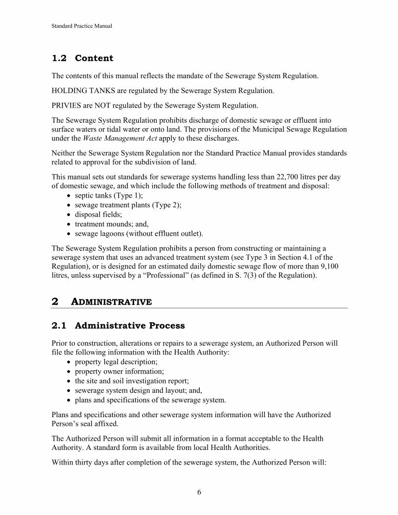
1.2 Content
The contents of this manual reflects the mandate of the Sewerage System Regulation.
HOLDING TANKS are regulated by the Sewerage System Regulation.
PRIVIES are NOT regulated by the Sewerage System Regulation.
The Sewerage System Regulation prohibits discharge of domestic sewage or effluent into surface waters or tidal water or onto land. The provisions of the Municipal Sewage Regulation under the Waste Management Act apply to these discharges.
Neither the Sewerage System Regulation nor the Standard Practice Manual provides standards related to approval for the subdivision of land.
This manual sets out standards for sewerage systems handling less than 22,700 litres per day of domestic sewage, and which include the following methods of treatment and disposal:
• septic tanks (Type 1); • sewage treatment plants (Type 2); • disposal fields; • treatment mounds; and, • sewage lagoons (without effluent outlet).
The Sewerage System Regulation prohibits a person from constructing or maintaining a sewerage system that uses an advanced treatment system (see Type 3 in Section 4.1 of the Regulation), or is designed for an estimated daily domestic sewage flow of more than 9,100 litres, unless supervised by a “Professional” (as defined in S. 7(3) of the Regulation).
2 ADMINISTRATIVE
2.1 Administrative Process
Prior to construction, alterations or repairs to a sewerage system, an Authorized Person will file the following information with the Health Authority:
• property legal description; • property owner information; • the site and soil investigation report; • sewerage system design and layout; and, • plans and specifications of the sewerage system.
Plans and specifications and other sewerage system information will have the Authorized Person’s seal affixed.
The Authorized Person will submit all information in a format acceptable to the Health Authority. A standard form is available from local Health Authorities.
Within thirty days after completion of the sewerage system, the Authorized Person will:
6

Standard Practice Manual
• file a letter certifying compliance with the Regulation to the Health Authority, and • provide the owner and Health Authority with the sewerage system operations,
specifications, commissioning details (start-up), maintenance plan and the name of a possible certified maintenance provider.
If the AP does not file a letter of certification within one year of filing initial information about the sewerage system, the Authorized Person must not start or continue construction of the sewerage system until filing new information.
2.2 Filing Cancellation
A file can be cancelled when: • information is determined to be false and/or misleading, and • changes to the application are sufficient to warrant cancellation.
At the time of cancellation, the Health Authority will notify any additional authorities having jurisdiction over the affected property.
2.3 Filing Notification Referrals
The Health Authority may notify the local building inspection department or local government authority about the filed sewerage system.
Notification may not be required when: • wastewater system repairs or alterations of an existing developed property will not
affect the building envelope or change the physical placement of the system.
2.4 Privacy
The Freedom of Information and Protection of Privacy Act will govern the information provided, as part of the filing process, and will be released in accordance with the provision of the Act.
2.5 Other Administrative Jurisdictions
It is the responsibility of the Authorized Person to: • ensure that all local zoning and/or bylaws are complied with; and, • notify the Health Authority regarding any conflicts arising from failure to comply with
local zoning and/or bylaws.
2.6 Restrictive Covenants
The Authorized Person(s) will need to ensure that: • the filing under Section 8 of the Regulation includes a copy of and complies with, any
covenants attached to the property title.
7

Standard Practice Manual
2.7 Use of Adjacent Property
The use of a sewerage system on adjacent property must: • meet all conditions of the Regulation; and, • be protected by easements and covenants.
A sewerage system can be constructed on adjacent property when: • there is no suitable area for construction or repair on the primary property; and, • a system needs repairing and there is no reserve area for the new field.
A sewerage system can be connected to another sewerage system upon an adjacent property when:
• there is no suitable area for construction or repair on the primary property; • the sewerage system on the adjacent lot can adequately accept the additional load; and, • the sewerage system on the adjacent lot will not create a problem or contributes to a
health risk.
2.8 Easements and Covenants
The use of an adjacent property will need to be: • registered with the local Health Authority; and • secured by an easement protected by covenant that is prepared by a qualified lawyer.
Any changes to registered covenant(s) will require agreement by the Health Authority.
2.9 New Systems
All systems subject to the Sewerage System Regulation must meet or exceed the standards outlined in this manual unless the design, installation and/or maintenance is supervised by a Professional within their scope of practice and exercising professional discretion within their area of expertise.
2.10 Repairs and Replacements
Where a sewerage system constructed prior to May 31, 2005 is in need of repair or replacement and the work cannot be done in accordance with the Sewerage System Standard Practice manual, the authorized person may deviate from the manual only to the degree necessary to repair or replace the system in a manner that will not create a health hazard.
In emergency situations, an authorized person may carry out the works necessary to eliminate health hazard arising from failed or failing systems and to maintain the function of that system until permanent repairs or replacements can be carried out in accordance with the Standard Practice manual.
Where the site constraints in Table 5-1 dictate, a Professional must supervise the repair or replacement of a system.
8

Standard Practice Manual
Existing systems that are subject to repairs or replacement shall be brought into compliance with the Sewerage System Standard Practice manual where practicable.
All regulatory filing provisions apply
2.10.1 Component Repair or Replacement Authorized Persons will not be required to prepare and submit a “filing” document to the Health Authority for the repair or replacement of any minor parts of the system such as: 2 liquid level float switch; 3 pump of exact same brand and model; 4 level of D Box adjustment; 5 tank inlet or outlet fittings; 6 septic tank effluent filters cleaning or replacing; 7 dispersal field lines flushing or vacuuming; or, 8 a dispersal field line or pipe section replacement when the pipe is broken or damaged
to the point where it is not working or likely to work.
2.10.2 System Repair or Replacement Authorized Persons must prepare and submit a “filing” document to the Health Authority for the repair or replacement of any major item of the system such as adding to or replacing septic/pump tanks, dispersal systems (trenches, beds, mounds), and lagoon cells. Where the existing system has failed due to increases in daily sewage flow rates the repair or replacement shall be made to accommodate the increase in daily sewage flow.
2.11 Seasonal Dwellings with No Hydro Connection
Seasonal use systems must be installed in compliance with the Sewerage System Standard Practice manual.
If it is not possible to apply this manual because of the site constraints, seasonal use of the property and limited water use, the Authorized Person may deviate from the manual for construction methods, only to the degree necessary to create a system that does not or will not create a health hazard.
Type 2 or Type 3 systems should not be used for seasonal dwellings as these systems are typically dependant on hydro for electrical components and may rely on biological processes that cannot be sustained under seasonal conditions.
To determine the degree of site constraint(s) refer to Table 5-1 (Site Constraints). Where site constraints dictate, a Professional must supervise the repair, replacement or installation of a system.
9

Standard Practice Manual
2.12 Multiple Homes on Same Property
When two homes will occupy one property the Authorized Person(s) will ensure that the single or combined sewerage system complies with the Sewerage System Regulation and Sewerage System Standard Practice Manual.
3 ROLES AND RESPONSIBILITIES
3.1 Health Authority
Health Authorities have statutory authority under the Health Authorities Act to: • administer the Sewerage System Regulation; • carry out legal remedies such as orders or tickets; • accept documents for filing and certification of systems; • ensure documents meet the Regulation; • ensure that only an Authorized Person construct or maintain the installed sewerage
system; and, • inspect and take corrective action to alleviate health hazards related to onsite
wastewater systems.
3.2 Authorized Person
An Authorized Person:
• has specific understanding of all of the integrated components and their application for the proper performance of a sewerage system;
• is familiar with the practice of developing plans, details, specifications, instructions, or inspections in the analysis of soil morphology, hydrology, geology, site layout, collection, conveyance, dispersal, sewage treatment technologies and their classifications;
• has a comprehensive knowledge of how the sewerage system being designed works and has the ability to evaluate and repair systems;
• is responsible for correctly identifying site conditions and assigning wastewater loading rates;
• prepares a comprehensive written site/soil evaluation report;
• uses the site/soil evaluation report to plan the sewerage system, including placement of components, tank sizing, effluent quality classification, treatment process, sub-surface effluent dispersal method, sub-surface effluent dispersal sizing and reserve area requirements.
10
Standard Practice Manual
• in consultation with the property owner, applies good judgment to prepare a plan that addresses the limitations of the property in compliance with the Sewerage System Regulation and with regard to the Standard Practice Manual;
• ensures that sewerage systems are planned, installed and operated ethically, competently and with due diligence;
• provides documentation in a clear format and files plans and specifications of the sewerage system in a manner acceptable to the Health Authority;
• ensures plans and specifications are consistent with the Sewerage System Standard Practice Manual;
• when the sewerage system is completed, provides a letter of certification to the Health Authority that the sewerage system was installed in accordance with filed plans and standard practices;
• starts and tests the sewerage system to verify that all equipment is functioning as intended; and,
• provides the homeowner and the Health Authority with the sewerage system maintenance plan.
• A maintenance plan is a set of instructions for maintaining a sewerage system that, if followed, will ensure that the sewerage system does not cause, or contribute to, a health hazard.
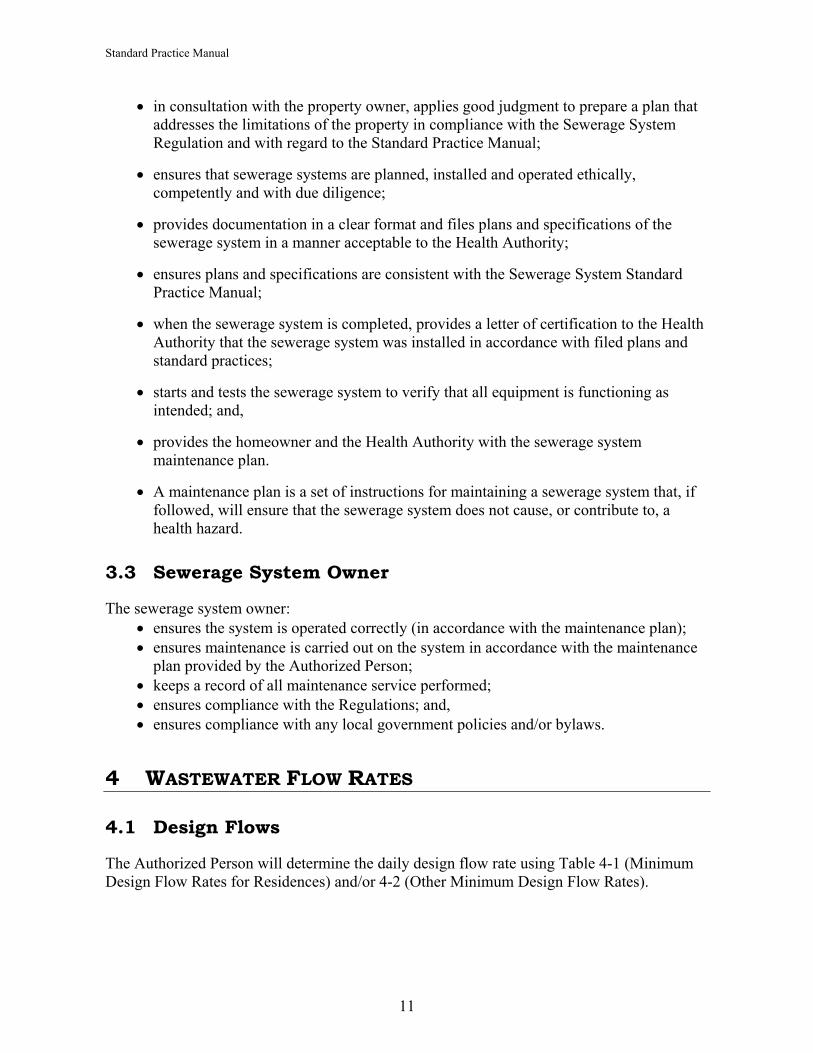
3.3 Sewerage System Owner
The sewerage system owner: • ensures the system is operated correctly (in accordance with the maintenance plan); • ensures maintenance is carried out on the system in accordance with the maintenance
plan provided by the Authorized Person; • keeps a record of all maintenance service performed; • ensures compliance with the Regulations; and, • ensures compliance with any local government policies and/or bylaws.
4 WASTEWATER FLOW RATES
4.1 Design Flows
The Authorized Person will determine the daily design flow rate using Table 4-1 (Minimum Design Flow Rates for Residences) and/or 4-2 (Other Minimum Design Flow Rates).
11

Standard Practice Manual
4.2 Minimum Design Flow Rates for Residences
The minimum flow rates for residences are in Table 4-1. These values include a safety factor.
The minimum design flow is a function of the number of bedrooms and the floor area as it is or could be finished for occupancy in the foreseeable future. To make sure the home is served by a sewerage system that is sized properly, the sewerage system must be based on the potential number of bedrooms in the house. Residential design flows will be used based on the declarations of developed living area provided by the building owner.
4.2.1 Flow Reduction Devices There must be no reduction in the design flow rate for the use of flow reduction devices.
4.3 Garbage Grinders (Garburators)
4.3.1 Treatment Where garbage grinders or garberators will be used, an increase in design flow of 50 percent is required for the treatment system.
4.3.2 Distribution Distribution field design flow rates remain the same as for systems not using garberators.
Table 4-1: Minimum design flow rates for residences
Residence Size Minimum Design Flow litres/gallons
1 and 2 bedroom unit up to 150 m2 1,600 sq. ft. 1,136/250
3 bedroom unit up to 175 m2
1,885 sq. ft. 1,363/300
4 bedroom unit up to 235 m2
2,530 sq. ft. 1,700/375
5 bedroom unit up to 295 m2
3,175 sq. ft. 2,045/450
6 bedroom unit up to 355 m2
3,820 sq. ft. 2,500/550
For every additional m2 add 5/1
4.4 Other Minimum Design Flow Rates
It is the responsibility of the Authorized Person to determine a reasonable estimate of the typical flow rate from tables 4.1 and 4.2. For existing facilities, water or sewage flow measurements should also be considered.
Typical unit flows for many types of facilities are shown in Table 4-2. These values represent estimates of flow rates since each facility is unique.
12

Standard Practice Manual
Provision of flow measurement by metre, pump cycles and/or duration should be considered in the design of treatment and disposal facilities.
4.4.1 Design Non-Residential Waste Design Flows Table 4-2 is used to determine the design flow for non-residential facilities. Where commercial kitchen equipment will be used in a facility, high strength waste is expected and a Professional is required for system design.
13

Standard Practice Manual
Table 4-2: Other minimum design flow rates
Institutional Unit Design Flow Rate (litres/gallon per
day) Assembly Halls no kitchen Per person 8/1.75 Assembly Halls with kitchen Per person 9/2 Church no kitchen Per seat 26/6 Church with kitchen Per seat 9/2 Church Suppers Per person 45/10 Town Hall Per seat 19/4 Fire station Per person 19/4
Medical/Personal Care Unit Design Flow Rate (litres/gallon per
day) Hospital Per bed 409/90 Including laundry Per bed 750/165 Excluding laundry Per bed 550/120 Hospital mental Per bed 340/75 Add per employee Per employee 23/5 Special care home Per resident 136/30 Add per employee Per employee 45/10 Medical Office Doctors nurses medical staff Per person 273/60
Office staff add Per person 73/16 Patient add Per person 23/5 Dental Office Per chair 757/166 Staff add Per person 132/29
Schools Unit Design Flow Rate (litres/gallon per
day) Cafeteria & gym & shower Per student 68/15 Cafeteria only Per student 45/10 Gym only Per student 68/15 Washrooms only Per student 13.5/3 Elementary Per student 26/6 High school Per student 45/10 Junior High school Per student 34/7.5 Boarding school Per student 136/30 Boarding school Per person 45/10
Prison Unit Design Flow Rate (litres/gallons per
day) Prison Per inmate 136/30 Add for personnel Per person 23/5
14

Standard Practice Manual
Food Service Unit Design Flow Rate (litres/gallons per
day) Bakery Per employee 68/15 Bar/lounge Per seat 125/27 Taverns/Bars/Lounges with minimal food service Per seat 76/16
Restaurant Per seat 31/7 Restaurant with food grinder Per seat 23/5 24 hour restaurant Per seat 189/41 24 hour highway Per seat 265/58 24 hr highway & showers Per seat 400/88 Kitchen & toilet waste only Per seat 113/25 Kitchen and toilet waste only Per patron 30/6.5 Banquet rooms Per seat 30/6.5 Drive-in restaurant Per seat 125/27 Night Club/Restaurant Per seat 113/25 Dining rooms and lounges Per m2 of dinning area 0.9/.2 Take out Per m2 0.19/.04 Banquet and Dining rooms Per m2 0.14/.03 Caterers Per patron 45/10 Cafeteria Per customer 4.5/.10 Coffee Shop Per customer 19/4 Coffee shop Per employee 36/8
Commercial Airport Unit Design Flow Rate (litres/gallons per
day) Airport Per passenger 9/2 Airport Per employee 41/9
Commercial Beauty Salon Unit Design Flow Rate (litres/gallons per
day) Beauty salon Per station 400/88 Beauty salon Per person 38/8
Commercial Veterinary Unit Design Flow Rate (litres/gallons per
day) Veterinary clinic (3 doctors or less) No boarding Total 2,900/638
Veterinary clinic (3 doctor or less) Boarding Total 5,700/1254
Dog kennel Per enclosure 73/16
15

Standard Practice Manual
Commercial Laundry Unit Design Flow Rate (litres/gallons per
day) Laundromat Per wash 168/37 Laundromat In apartment Per machine 1,135/250
Department Store Unit
Design Flow Rate (litres/gallons per
day) Department store Per toilet room 1,513/333 Department store Per employee 36/8 Shopping centre Per employee 40/9 Shopping centre Washrooms Per m2 of store space 5/1 Shopping centre Toilet rooms Each 1,665/366 Centre with no café or laundry Per m2 7/1.5 Large dry goods centre Per m2 2/.45 Large supermarket & meat department Per m2 3/.6 Small dry goods store Each 379/83
Commercial Automotive Unit Design Flow Rate (litres/gallons per
day) Automobile gas station Per vehicle 22/5 Gas station Per catch basin in floor 372/82 Gas station Double pump Per unit 568/125 Automobile gas station island Per island 2,000/440 Automobile gas station Per vehicle 38/8 Car wash Per car 189/42 Truck wash Per truck 378/83
Commercial Hospitality Unit Design Flow Rate (litres/gallons per
day) Motel Bath & toilet only Per person 118/26 Motel Full housekeeping Per person 180/40 Motel Per unit 318/70 Motel Per housekeeping unit 455/100 Motel with Dining room Per seat 122/27 Motel Bar and lounge Per seat 68/15 Motel Bed & breakfast Per person 27/6 Hotel Per guest 136/30 Hotel Per employee 36/8 Boarding house Per resident 150/33 Dormitory Bunkhouse Per person 91/20 Senior citizen home Per resident 227/50 Day care centres Per employee 73/16
16

Standard Practice Manual
Industrial/Office Unit Design Flow Rate (litres/gallons per
day) Industrial buildings Excluding industrial waste, cafeteria and showers Per employee 45/10
Industrial buildings Excluding industrial waste, including showers Per employee 75/16
Heavy Industry Excluding industrial waste, including cafeteria & shower Per employee 132/29
Warehouse Per employee 132/29 Industrial Park Per acre 63,644/14000 Industrial Park Per employee 68/15 Office No cafeteria Per employee 50/11 Office Including cafeteria Per employee 76/16 Town offices Office employees Per employee 57/12.5 Town Offices Transients Per person 19/4 Unspecified Office Space Per m2 613/135
Recreation Camping Unit Design Flow Rate (litres/gallons per
day) Campgrounds tents only Per site 180/39 Campsites non year round Per site 365/80 Having year round operation Per site 545/120 Cabin Resort Per person 159/35 Day camps no meal Per person 38/8 Day camps with meals Per person 68/15 Day camps Per person 40/9 Construction camps flush toilets Per person 189/41 Construction camps no flush toilets Per person 123/27 Youth camps Per person 189/41 Work camps Per bed 227/50 Cottages & small seasonal dwellings Per unit 189/41
Parks and Picnic Grounds Unit Design Flow Rate (litres/gallons per
day) Picnic & fairgrounds with bath houses, showers, toilets Per person 38/8
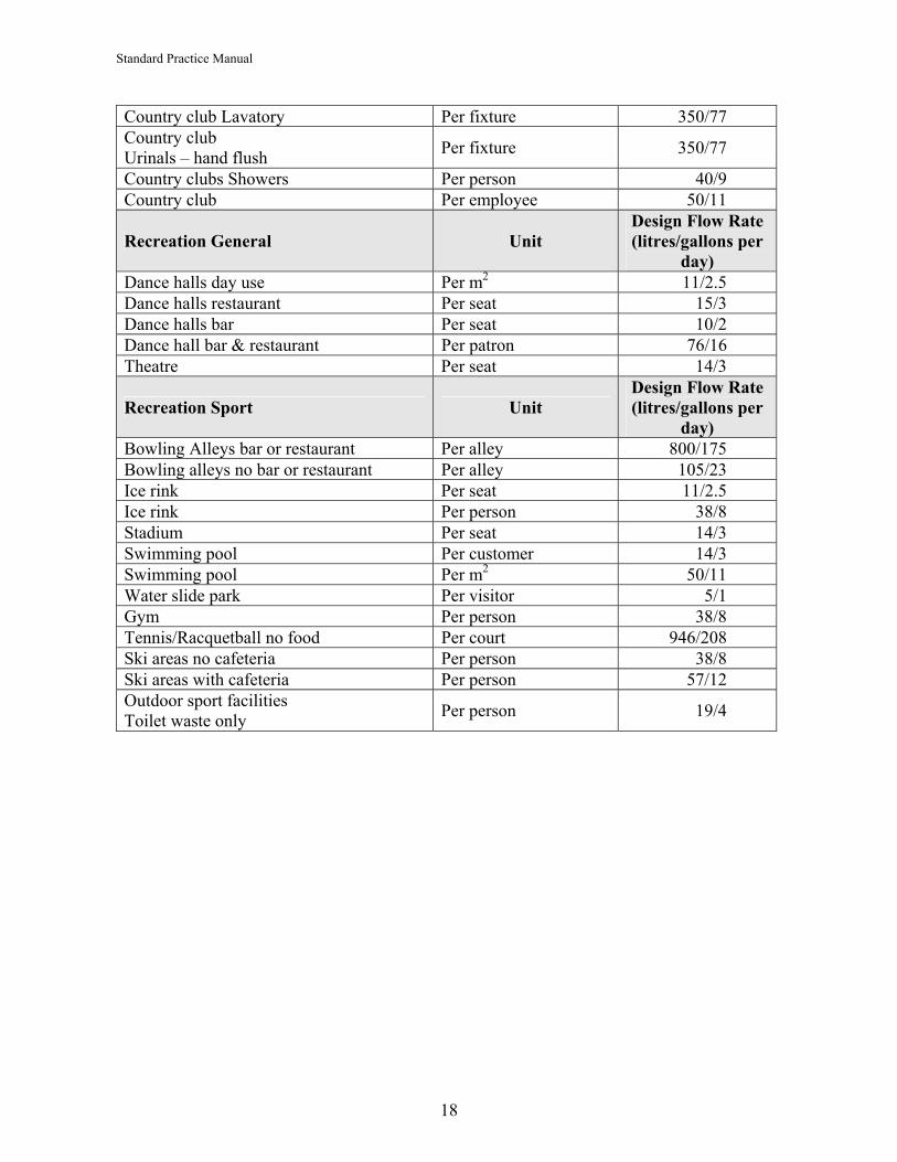
Picnic & fairgrounds with toilet only Per person 18/4 Beaches with showers & toilets Per person 40/9 Visitor Centre Per person 23/5 Country club Resident present Per person 372/81 Country club Non resident Per person 95/20 Country club Showers in use Per fixture 1,800/395 Country club Water closet Per fixture 550/120
17
Standard Practice Manual
Country club Lavatory Per fixture 350/77 Country club Urinals – hand flush Per fixture 350/77
Country clubs Showers Per person 40/9 Country club Per employee 50/11
Recreation General Unit Design Flow Rate (litres/gallons per
day) Dance halls day use Per m2 11/2.5 Dance halls restaurant Per seat 15/3 Dance halls bar Per seat 10/2 Dance hall bar & restaurant Per patron 76/16 Theatre Per seat 14/3
Recreation Sport Unit Design Flow Rate (litres/gallons per
day) Bowling Alleys bar or restaurant Per alley 800/175 Bowling alleys no bar or restaurant Per alley 105/23 Ice rink Per seat 11/2.5 Ice rink Per person 38/8 Stadium Per seat 14/3 Swimming pool Per customer 14/3 Swimming pool Per m2 50/11 Water slide park Per visitor 5/1 Gym Per person 38/8 Tennis/Racquetball no food Per court 946/208 Ski areas no cafeteria Per person 38/8 Ski areas with cafeteria Per person 57/12 Outdoor sport facilities Toilet waste only Per person 19/4
18

Standard Practice Manual
5 DETERMINATION OF TREATMENT AND DISPOSAL REQUIREMENTS
5.1 Process Selection
The selection of the treatment system and the effluent disposal system primarily depends on the design flow, the constraints of the site, the setback requirements and the land area available for the disposal system. Section 4 provides information on the design flow rates. Section 5 provides information on the other necessary considerations.
5.2 Levels of Treatment
The Sewerage System Regulation and the Standard Practice Manual are structured around specific levels of treatment prior to discharge into the ground. As defined in the Sewerage System Regulation:
• Type 1 is treatment by septic tank only; • Type 2 is treatment that produces an effluent consistently containing less than 45 mg/L
of total suspended solids and having a 5 day biochemical oxygen demand (BOD5) of less than 45 mg/L; and,
• Type 3 is treatment that produces an effluent consistently containing less than 10 mg/L of total suspended solids and having a 5 day biochemical oxygen demand (BOD5) of less than 10 mg/L, and a median fecal coliform density of less than 400 Colony Forming Units (cfu) per 100 mL.
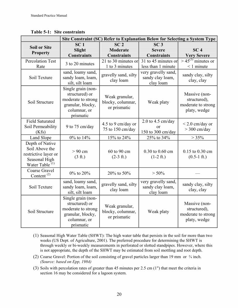
5.3 Site Constraints for Sewage Treatment Selection
Use Table 5-1 (Site Constraints) following to select an onsite sewage treatment system. The overall class (1 to 4) is based on the worst case for each of the rows. For example, if the percolation rate, soil permeability, and land slope are all Class 1, and the depth to bedrock is Class 3, the overall class is Class 3 (Severe Constraints). In all cases, the sewerage system selected or designed must address all severe and very severe constraints identified from Table 5-1.
19
Standard Practice Manual
Table 5-1: Site constraints Site Constraint (SC) Refer to Explanation Below for Selecting a System Type
Soil or Site Property
SC 1 Slight
Constraints
SC 2 Moderate
Constraints
SC 3 Severe
Constraints SC 4
Very Severe Percolation Test
Rate 3 to 20 minutes 21 to 30 minutes or1 to 3 minutes
31 to 45 minutes or less than 1 minute
> 45(3) minutes or < 1 minute
Soil Texture sand, loamy sand, sandy loam, loam,
silt, silt loam
gravelly sand, silty clay loam
very gravelly sand, sandy clay loam,
clay loam
sandy clay, silty clay, clay
Soil Structure
Single grain (non-structured) or
moderate to strong granular, blocky,
columnar, or prismatic
Weak granular, blocky, columnar,
or prismatic Weak platy
Massive (non-structured),
moderate to strong platy, wedge
Field Saturated Soil Permeability
(Kfs) 9 to 75 cm/day 4.5 to 9 cm/day or
75 to 150 cm/day
2.0 to 4.5 cm/day or
150 to 300 cm/day
< 2.0 cm/day or > 300 cm/day
Land Slope 0% to 14% 15% to 24% 25% to 34% > 35% Depth of Native Soil Above the
restrictive layer or Seasonal High Water Table (1)
> 90 cm (3 ft.)
60 to 90 cm (2-3 ft.)
0.30 to 0.60 cm (1-2 ft.)
0.15 to 0.30 cm (0.5-1 ft.)
Coarse Gravel Content (2) 0% to 20% 20% to 50% > 50% —
Soil Texture sand, loamy sand, sandy loam, loam,
silt, silt loam
gravelly sand, silty clay loam
very gravelly sand, sandy clay loam,
clay loam
sandy clay, silty clay, clay
Soil Structure
Single grain (non-structured) or
moderate to strong granular, blocky,
columnar, or prismatic
Weak granular, blocky, columnar,
or prismatic Weak platy
Massive (non-structured),
moderate to strong platy, wedge
(1) Seasonal High Water Table (SHWT): The high water table that persists in the soil for more than two weeks (US Dept. of Agriculture, 2001). The preferred procedure for determining the SHWT is through weekly or bi-weekly measurements in perforated or slotted standpipes. However, where this is not appropriate, the depth of the SHWT may be estimated from soil mottling and root depth.
(2) Coarse Gravel: Portion of the soil consisting of gravel particles larger than 19 mm or ¾ inch. (Source: based on Epp, 1984)
(3) Soils with percolation rates of greater than 45 minutes per 2.5 cm (1") that meet the criteria in section 16 may be considered for a lagoon system.
20

Standard Practice Manual
5.4 Selecting a Treatment System Based on Site Constraint (SC)i
SC 1: Use a Type 1, 2, or 3 treatment system with gravity or pressure distribution to subsurface trenches, or pressure distribution to at-grade chambers.
SC 2: Refer to Table 5.2 (Required Vertical Separation). Use either:
(a) Type 1 with pressure distribution to shallow trenches (as required to meet Table 5-2);
Type 1 with pressure distribution to a sand mound (as required to meet Table 5-2);
Type 2 with pressure distribution to shallow subsurface trenches or at grade chambers; or,
Type 3 with pressure distribution to subsurface trenches.
SC 3: Use either:
(a) Type 2 with pressure distribution to shallow trenches (as required to meet Table 5-2);
(b) Type 2 with pressure distribution to a sand mound (as required to meet Table 5-2); or
(c) Type 3 system designed by a Professional.
SC 4: Use either:
(a) Type 3 sewage treatment system with shallow trenches or a sand mound (as required to provide vertical separation) designed by a Professional, or,
(b) Lagoon system in accordance with section 16
5.5 Required Vertical Separation
Use Table 5-2 (Required Vertical Separation) to first determine the required depth of native soil prior to system installation, and then the required minimum allowable vertical separation, depending on the type of treatment system used.
The minimum vertical separation is the vertical distance from the infiltration surface (trench bottom) to the seasonal high water table or limiting layer (clay, rock), as in Figure 5-1 (Vertical separation between the infiltrative surface and the restrictive layer). With a sand mound, this vertical distance will include some native soil and some imported sand fill. With subsurface trenches or an at-grade system, this vertical distance includes only native soil.
21

Standard Practice Manual
Table 5-2: Required vertical separation Minimum Required Depth of Unsaturated Native Soil (prior to system installation)
Sewage Treatment Used (Centimetres) (inches) Type 1 60 cm 24" Type 2 45 cm 18" Type 3 30 cm 12"
Minimum Allowable Vertical Separation
(installed infiltrative surface to limiting layer) (Centimetres) (inches) Type 1 90 cm 36" Type 1 Pressure distribution
60 cm 24"
Type 2 60 cm 24" Type 3 60 cm 24"
Figure 5-1: Vertical separation between the infiltrative surface and the restrictive layer.
5.6 Hydraulic Loading Rates
The effluent loading rate is the amount of effluent that can be applied each day over a basal (bottom) area of infiltrative surface without compromising the permeability or conductive capacity of the soil.
The sizing and configuration of subsurface soil-based treatment and dispersal processes is based on how the effluent moves away from and the rate at which it moves away from the distribution area.
22

Standard Practice Manual
23
For selection of a soil hydraulic loading rate for an onsite sewerage system use at least two of the three methods listed below, using Table 5-3 (Selection of a soil hydraulic loading rate). Appendices B, C and D respectively describe the required procedures for carrying out percolation tests, assessing soil texture and structure, and carrying out permeability tests to determine the soil hydraulic conductivity:
• percolation tests (See Appendix B); • soil texture and structure assessments; and, • soil hydraulic conductivity (K) tests (See Appendix D).
At least one of the methods used must be soil texture and structure.ii (Also reference Appendix C: Recommendations for Field Tests of Soil Permeability.)
If the two methods used lead to different hydraulic loading rates, use the most conservative rate — the lower hydraulic loading rate — resulting in a larger drainfield size.

Table 5-3: Wastewater Loading Rates for Residential Strength Wastewater Soil Characteristics1
Structure Wastewater Loading Rates
gallons/ft2/day (litres/m2/day)2
Texture (USDA) Shape Grade
Percolation Rates
(min/2.54 cm)
Field Saturated Hydraulic
Conductivity (Kfs) mm/day Type 1 Type 2 Type 3
Gravelly sand* — Single grain < 2 > 2000 0.8 (39) 1.6 (78) 2.4 (117) Coarse to medium sand/loamy sand — Single grain 2 – 5 1000 – 2000 0.7 (34) 1.4 (68) 2.1 (103)
Fine sand and fine loamy sand — Single grain 5 – 15 250 – 1000 0.6 (29) 1.2 (59) 1.8 (88)
massive structureless 0.3 (15) 0.45 (22) 0.6 (29) weak 0.3 (15) 0.45 (22) 0.6 (29) platy moderate, strong
20 – 30
125 – 250
not recommended not recommended not recommended weak 0.4 (20) 0.7 (34) 1.0 (49)
Sandy loam prismatic, blocky, granular moderate, strong 10 – 20 250 – 500 0.5 (25) 1.0 (49) 1.5 (74) massive structureless 0.2 (10) 0.3 (15) 0.4 (20)
weak 0.2 (10) 0.3 (15) 0.4 (20) platy moderate, strong 30 – 40 60 – 125
not recommended not recommended not recommended weak 0.3 (15) 0.5 (24) 0.7 (34)
Loam prismatic, blocky, granular moderate, strong 20 – 30 125 – 250 0.4 (20) 0.8 (39) 1.2 (59) massive structureless 0.2 (10) 0.3 (15) 0.4 (20)
weak 0.2 (10) 0.3 (15) 0.4 (20) platy moderate, strong 40 – 60 30 – 60
not recommended not recommended not recommended weak 0.3 (15) 0.5 (24) 0.7 (34)
Silt loam, silt prismatic, blocky, granular moderate, strong 20 – 40 60 – 250 0.4 (20) 0.8 (39) 1.2 (59) massive structureless not suitable not suitable not suitable
weak not suitable not recommended not recommended platy moderate, strong 60 – 90 15 – 30
not suitable not suitable not suitable weak 0.2 (10) 0.3 (15) 0.4 (20)
Clay loam, sandy clay loam, silty clay loam* prismatic,
blocky, granular moderate, strong 40 – 60 30 – 60 0.3 (15) 0.45 (22) 0.6 (29) massive structureless not suitable not suitable
weak not recommended not recommended platy moderate, strong not suitable not suitable weak 0.15 (7) 0.18 (9)
Sandy clay, silty clay, clay*3
prismatic, blocky, granular moderate, strong
90 – > 120 < 5.0 – 60 not suitable
0.2 (10) 0.25 (13)
24
Standard Practice Manual

Standard Practice Manual
Footnotes for Table 5-3: Wastewater Loading Rates for Residential Strength Wastewater * Indicates soil conditions where pressure distribution systems should be used for all levels
of pre-treatment (i.e., Type 1, 2 and 3). (1) Soil characteristics are to be evaluated and described in accordance with the following
recognized and established methods: • Canadian System of Soil Classification, 3rd Edition • CanSIS Manual for Describing Soils in the Field (Working Group on Soil Survey Data 1975) • Book for Describing and Sampling Soils, Natural Resources Conservation Service, USDA
(1998)
• Standard Practice for Subsurface Site Characterization of Test Pits for On-Site Septic Systems (ASTM, D 5921 – 96; re-approved 2003)
Soils with consistence stronger than hard (dry), firm (moist), sticky or slightly plastic (wet), or of any cemented class are considered unsuitable.
(2) Loading rates apply to the soil characteristics of the horizon in which the infiltration surface of the dispersal system will be situated as well as the characteristics of the underlying soil. It is recommended that the loading rate be based on the horizon(s) with the most limiting soil characteristics.
It is recommended that other soil characteristics, such as coarse fragments (e.g., gravel), soil color, roots, and moisture conditions be included in loading rate assessment,
Soils labeled as ‘not recommended’ are to be considered only when (a) an appropriate loading rate can be justified, (b) Type 2 or 3 effluent is utilized, and (c) the effluent is timed dosed using a pressure distribution system
(3) These loading rates do not apply if the soil contains greater than 40% clay and/or significant amounts of expandable clay minerals (smectite, vermiculite). In addition, advanced Type 2 effluent (< 10 mg/L BOD and TSS) or Type 3 effluent must be used.
25

Standard Practice Manual
5.7 Setback Requirements
Tables presented in this section are the minimum required standards for all sewerage systems. Deviation from the tables can only be made by a “Professional” as defined in the Regulation. All setbacks must be measured from the infiltrative surface (i.e., trench wall) to the nearest edge of the restriction (i.e., well, building)
Table 5-4: Horizontal setback distances From edge of distribution system4
(metres/feet) From watertight subsurface treatment
tank (metres/feet) Distance to Lagoon Type 11 Type 21 Type 31
Septic1 Type 2 – 31
Property lines 15 m/ 50 ft.
3 m/ 10 ft.
1.5 m/ 5 ft.
1 m/ 3 ft.
1 m/ 3 ft.
Source of drinking water, well or water suction lines 30 m/ 100 ft.2 15 m/
50 ft. 15 m/ 50 ft.
Water lines (pressure) 3 m/ 10 ft. 1.5 m/ 5 ft. 1 m/ 3 ft.
1 m/ 3 ft.
Up-gradient 3 m/ 10 ft. 1.5 m/ 5 ft. 1 m/
3 ft. 1 m/ 3 ft.
Drainage or building perimeter
drain Down-gradient 15 m/ 50 ft. 10 m/ 33 ft. 3 m/
10 ft. 3 m/ 10 ft.
Building non-dwelling 15 m/ 50 ft. 1.5 m/5 ft. 1 m/
3 ft. 1 m/ 3 ft.
1 m/ 3ft.
Building dwelling 60 m/ 200 ft. 3 m/10 ft. 2 m/
6 ft. 1 m/ 3 ft.
1 m/ 3 ft.
Up-gradient 60 m/ 200 ft. 3 m/ 10 ft. 2 m/
6 ft. 1 m/ 3 ft.
1 m/ 3 ft. With
basement Down-gradient
60 m/ 200 ft 9 m/ 30 ft. 6 m/
20 ft. 3 m/ 10 ft.
3 m/ 10 ft.
Break-out point 15 m/ 50 ft.
15 m/ 50 ft.
7.5 m/ 25 ft.
7.5 m/ 25 ft.
15 m/ 50 ft.
10 m/ 33 ft.
Utility services 1.5 m/ 5 ft. 1 m/ 3 ft. 1 m/ 3 ft. 1 m/ 3 ft.
60 m/ 200 ft.
30 m/ 100 ft. Fresh water
Marine water3 30 m/ 100 ft 15 m/ 50 ft.
15 m/ 50 ft.
10 m/ 33 ft.
10 m/ 33 ft.
(1) Any reduction of horizontal setback distances must be reported to the Health Authority, verified by the site/soil evaluation report and approved by a Professional.
26

Standard Practice Manual
(2) Any reduction of horizontal setback distances will require installation of environmental monitoring sampling wells to verify compliance with effluent quality parameters. Any setback from freshwater or source of drinking water less than 15 m/ 50 ft. requires an active local government by-law outlining monitoring and maintenance conditions.
(3) Measured from edge of water or high tide line. (4) For mound systems, setback will be from the nearest edge of the required infiltrative area (i.e.,
trench wall).
6 PIPING
6.1 Design Considerations
Piping must be graded and sized to allow for peak hydraulic flows of sewage. Peak flows are determined by the BC Plumbing Code fixture unit method and when pipes must be drained to prevent freezing.
Gravity piping should maintain a continuous and designed grade. Pressure distribution piping should be of sufficient size to deliver the required volume and pressure.
A building sewer, an effluent sewer or a distribution header (i.e., a manifold) must be evenly and continuously supported.
6.2 Installation Standards
It might be necessary to protect building sewers or effluent sewers from freezing by a frost box, culvert or other equivalent means, particularly if there is less than 1.2 m (4') of soil cover where it crosses under a ditch, driveway or path.
Piping for effluent sewers must not have a nominal pipe size smaller than 7.5 cm (3").
A 10 cm (4") building sewer or effluent sewer must have a minimum grade of 1% (1⁄8 inch per foot).
A 7.5 cm (3") building sewer or effluent sewer must have a minimum grade of 2% (1⁄4 inch per foot).
The BC Plumbing Code specifies that:
(1) a building sewer must not change direction or slope between the building and public sewer or between cleanouts, except that pipes not more than 6 inches in size may change direction
(i) by not more than 5º every 3 m, or
(ii) by the use of fittings with a cumulative change in direction of not more than 45º (S. 7.4.7.1), and
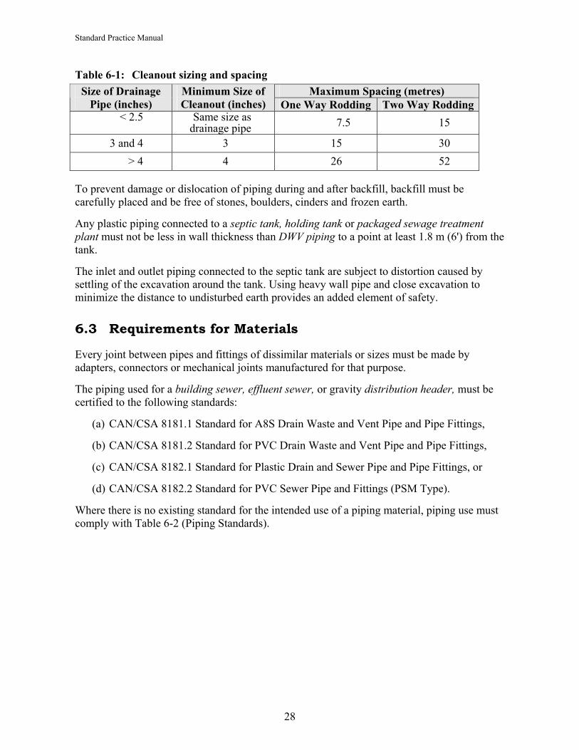
(2) the size and spacing of cleanouts must conform to the following table (S. 7.4.7.2):
27
Standard Practice Manual
Table 6-1: Cleanout sizing and spacing Maximum Spacing (metres) Size of Drainage
Pipe (inches) Minimum Size of Cleanout (inches) One Way Rodding Two Way Rodding
< 2.5
Same size as drainage pipe 7.5 15
3 and 4 3 15 30 > 4 4 26 52
To prevent damage or dislocation of piping during and after backfill, backfill must be carefully placed and be free of stones, boulders, cinders and frozen earth.
Any plastic piping connected to a septic tank, holding tank or packaged sewage treatment plant must not be less in wall thickness than DWV piping to a point at least 1.8 m (6') from the tank.
The inlet and outlet piping connected to the septic tank are subject to distortion caused by settling of the excavation around the tank. Using heavy wall pipe and close excavation to minimize the distance to undisturbed earth provides an added element of safety.
6.3 Requirements for Materials
Every joint between pipes and fittings of dissimilar materials or sizes must be made by adapters, connectors or mechanical joints manufactured for that purpose.
The piping used for a building sewer, effluent sewer, or gravity distribution header, must be certified to the following standards:
(a) CAN/CSA 8181.1 Standard for A8S Drain Waste and Vent Pipe and Pipe Fittings,
(b) CAN/CSA 8181.2 Standard for PVC Drain Waste and Vent Pipe and Pipe Fittings,
(c) CAN/CSA 8182.1 Standard for Plastic Drain and Sewer Pipe and Pipe Fittings, or
(d) CAN/CSA 8182.2 Standard for PVC Sewer Pipe and Fittings (PSM Type).
Where there is no existing standard for the intended use of a piping material, piping use must comply with Table 6-2 (Piping Standards).
28

Standard Practice Manual
Table 6-2: Piping standards
Type of Piping Standard Reference
Gravity Sewage or Effluent Piping
PressureEffluent
Line
Weeping Lateral Piping
Pressure Effluent
DistributionLateral
Polyethylene water pipe and tubing Series 160 with compression fittings Series 50, 75, 100 and 125
CAN3-B137.1-M N P N N
Poly vinyl chloride (PVC) water pipe Series 60, 100, 125, 160 and 200
CAN3-B137.3-M P P P P
Chlorinated poly vinyl chloride (CPVC) water pipe
CAN3-B137.6-M N N N P
Polybutylene water pipe CAN3-B137.8-M N P N N Plastic Sewer Pipe perforated non perforated
CAN/CSA-B182.1-M92
N P
N N
P N
N N
Corrugated Polyethylene perforated non perforated
CGSB 41-GP-31
N P
N N
P N
N N
Acrylonitrile- butadiene-styrene (ABS) DWV pipe
CAN/CSA-B181.1-M90 P N N N
Poly (vinyl chloride) (PVC) DWV pipe
CAN/CSA-B181.2-M90 P N N N
Type PSM PVC sewer pipe 35 SDR
CAN/CSA-B182.2-M90 P N N N
Profile poly (vinyl chloride) (PVC) sewer pipe PS 320 kPa
CAN/CSA-B182.6-M P N N N
Profile polyethylene sewer pipe PS 320 kPa
CAN/CSA-182.6-M P N N N
Cast iron soil pipe CAN3-B70-M P N N N P = Permitted N = Not Permitted
29
Standard Practice Manual
7 RAW WASTEWATER CONVEYANCE The raw wastewater ejector pump and transfer tank is used to convey raw wastewater from the facility to a septic tank where primary treatment can occur.
Authorized Persons must:
• follow BC Plumbing codes and other applicable standards for good plumbing practices.
• ensure that the pipes, pump and fittings are protected from freezing.
• equip the pump chamber with an audible high level alarm.
• ensure that electrical wiring complies with BC Electrical codes for wet and corrosive locations and be installed or inspected by a registered class C electrician or equivalent technician.
• ensure that sewage ejector transfer tank is structurally sound and watertight.
• provide adequate gas venting, either by provision of building drain and building sewer that connects to the stack vent on the building on by a separate vent.
• ensure that components are easily accessible and fitted with “quick disconnects” within 45 cm of the rim of the access riser for ease of maintenance and/or replacement. Use of cam lock type fittings is preferred over unions.
8 SEPTIC TANKS (TYPE 1) AND SEWAGE EFFLUENT TANKS
8.1 Design Considerations
8.1.1 General The septic tank functions as a primary treatment process and, by definition, produces a Type 1 effluent.
Septic tanks shall be two compartment tanks or two tanks in series with a total working volume outlined in Table 8-1.
Septic tanks must be structurally sound, watertight and corrosion-resistant and must meet or exceed the requirements of the current CSA Standard and the standards in this manual.
The septic tank will not house any means to dose or pump effluent that causes any variation in the total working volume of the tank required in Table 8-1 (Septic Tank Volume Requirements) in Section 8.1.2. Working (or liquid) volume is measured from the inside bottom of tank to invert of outlet.
When a septic tank has an integrated pump compartment the pump compartment volume will not be calculated as part of the working volume of the septic tank.
30

Standard Practice Manual
Figure 8-1 shows a typical two compartment tank. The configuration may vary but it must meet current CSA standards.
Figure 8-1: Compartmentalized septic tank.
If the chambers are provided in individual tanks, as in Figure 8-2, the discharge from the first tank should come from an outlet baffle from about ⅔ of the liquid depth from the bottom of the tank. The liquid volume of chambers in multiple tanks, single or multi-compartment, must be at least equal to the required volumes of each chamber of a two-chamber tank and sized accordingly (see Table 8-1)
Figure 8-2: Septic tank with multiple compartment provided by individual tanks.
Septic tanks must be properly fitted with a properly sized effluent filter with an effective capacity to filter particles greater than or equal to 3 mm. The effluent filter must be easily accessible for maintenance and inspection purposes. Effluent filters may also be installed in a separate chamber where installation in an existing septic tank is not practical. The effluent filter must pass a minimum flow rate 50% greater than the peak daily flow, and when 85% clogged, be able to pass a flow rate equivalent to the daily flow.
8.1.2 Septic Tank Volume Requirements Table 8-1 shows required septic tank volume for flows up to 22,700 L/d. Calculations for table 8-1 are as follows:
31

Standard Practice Manual
For design flows of up to 9,100 litres/day, septic tanks must have a minimum working volume of three days retention time based on minimum design wastewater flow from Section 4. The minimum working volume of a tank must be 3,408 litres.
For design flows from 9,100 litres/day to 22,700 litres/day, the minimum septic tank working volume will be the amount, V, calculated by:
V=15,000 + (Design Flow × 1.34)
Where: V = the minimum working volume in litres; and,
Design Flow = the design flow in litres/day obtained from Section 4 of this manual.
Working (or liquid) volume is measured from the inside bottom of the tank to invert of the outlet.
Table 8-1: Septic tank volume requirementsiii
Design Daily Sewage Flow
(gallons)
Design Daily Sewage
Flow (litres) Number of Bedrooms
Septic Tank working Volume (litres)
Septic TankWorking Volume (gallons)
250 1,136 or less
1 and 2 bedroom unit up to 150 m2 or 1,600 sq. ft. 3,408 750
300 1,363 3 bedroom unit up to 175 m2
1,885 sq. ft. 4,089 900
375 1,700 4 bedroom unit up to 235 m2
2,530 sq. ft. 5,100 1,125
450 2,045 5 bedroom unit up to 295 m2
3,175 sq. ft. 6,135 1,350
550 2,500 6 bedroom unit up to 355 m2
3,820 sq. ft. 7,500 1,650 660 3,000 9,000 1,980 880 4,000 12,000 2,640
1,100 5,000 15,000 3,300 1,320 6,000 18,000 3,960 1,540 7,000 21,000 4,620 1,760 8,000 24,000 5,280 1,980 9,000 27,000 5,940 2,200 10,000 28,400 6,250 2,420 11,000 29,740 6,545 2,640 12,000 31,080 6,835 2,860 13,000 32,420 7,130 3,080 14,000 33,760 7,425 3,300 15,000 35,100 7,720 3,520 16,000 36,440 8,015 3,740 17,000 37,780 8,310 3,960 18,000 39,120 8,600 4,180 19,000 40,460 8,900 4,400 20,000 41,800 9,195
32

Standard Practice Manual
4,620 21,000 43,140 9,490 4,840 22,000 44,480 9,785
22,700 45,418 9,990
8.1.3 Watertightness Testing All tanks should be tested for water tightness after installation where practical by filling with water (hydrostatic testing) or by vacuum testing. In both cases, the tank should be tested in the ready-to-use state. Inlets and outlets should be plumbed with the appropriate pipes, which can then be plugged for the test. Testing requirements may be found in Appendix H.
8.2 Installation Standards
8.2.1 General Septic tanks, or sewage effluent tanks must not be located within the setback distances laid out in Section 5.7, Table 5-4.
A septic tank must have an access opening for each chamber that is level with the finished grade and have the ground graded to slope away. In areas of extreme cold climate, the riser must be insulated to prevent the tank from freezing. Access openings will be over inlet and outlet baffles or effluent filters.
To increase safety and prevent unauthorized or accidental entry into a septic tank, access openings must be equipped with a secure lid or cover. Acceptable protective lid features include but are not limited to:
• a padlock; • a cover that can only be removed with tools; or, • a cover having a minimum weight of 29.5 kilograms (65 pounds); and,
have beveled edges to prevent the cover from falling into the riser or tank.
An access opening extension must be water tight at the connection to the septic tank, to the sewage holding tank and at the joints between all sections.
All tanks must be manufactured with flexible watertight connectors cast-in-place. Note: this requirement must be implemented May 2006.
8.2.2 Installation Authorized Persons must:
• locate all underground utilities before digging.
• ensure that all excavation, installation and backfilling work must comply with ‘Workers Compensation Occupational Health and Safety Regulation’ part 20.78.
• inspect tank prior to installation to ensure tank is not damaged.
• perform a watertightness test as described in Section 8.1.3.
33

Standard Practice Manual
• backfill the tank evenly on all four sides in 30 cm (12") lifts with compaction to final grade.
• ensure that manufacturers of tanks provide instructions for the handling, assembly and installation of their tanks.
• ensure that risers and lids are not shifted or distorted when backfilling.
The inlet and outlet piping connected to a tank must be protected from distortion caused by settling of the backfill material. The excavation for a tank should not be any longer than is necessary to install the tank. This provides undisturbed earth closer to the tank to support the inlet and outlet piping connected to the tank. Piping connected to the septic tank, and sewage holding tank must be supported to within 30 cm (12") of the tank on a solid base.
Pre-cast concrete tanks must not be shipped or installed until reaching design strength.
Septic Tank Abandonmentiv
When a septic tank is abandoned one of the following procedures must be taken in order to prevent future health and safety hazards:
• the contents of the tank are to be pumped out and the septic tank, if structurally sound, is to be filled with inorganic material such as soil or rock, or
• the septic tank is to be removed or broken up and the resulting excavation is to be filled with soil or rock.
• The soil absorption area can usually be left in its existing state.
9 TYPE 2 TREATMENT PLANTS
9.1 Design Considerations
Sewage that exceeds the maximum limits for residential strength sewage must not be discharged to a Type 2 treatment plant unless the plant is specifically designed for the treatment of high strength waste and the installation of the system is supervised by a Professional. Regardless of the effluent strength, all Type 2 plants must produce 45 mg/L BOD5 45 Total Suspended Solids prior to discharge in accordance with the Regulation.
Residential strength sewage means sewage that has a BOD5 of less than 250 mg/L, TSS of less than 250 mg/L, and oil and grease content of less than 30 mg/L.
The minimum treatment capacity of a Type 2 treatment plant must be not less than 1,365 litres (300 gallons) per day, and not less than the design sewage flow per day.
Access openings and manhole extensions must prevent water from entering the treatment plant.
34

Standard Practice Manual
9.2 Installation Standards
A Type 2 treatment plant must not be located within the required setback distances given in Section 5.7 Table 5-4.
A Type 2 treatment plant must be provided with an access opening at or above the ground surface. The treatment plant requires regular servicing and must be readily accessible.
Access openings must be equipped with a secure lid or cover to prevent unauthorized or accidental entry into the access treatment plant. Acceptable protective measures include but are not limited to:
• a padlock; • a cover that can only be removed with tools; or, • a cover having a minimum weight of 29.5 kilograms (65 pounds); and,
have beveled edges to prevent the cover from falling into the riser or tank.
An access opening extension must be water tight at the connection to the Type 2 treatment plant and at the joints between all sections.
The bottom of an excavation for a Type 2 treatment plant must provide a uniform base to support the tank in a level position.
Piping connected to the Type 2 treatment plant must be supported to within 300 mm (1') from the tank on a solid base, or equivalent. The inlet and outlet piping connected to a Type 2 plant must be protected from distortion caused by settling of the backfill material. The excavation for a Type 2 plant should not be any longer than is necessary to install the plant. This provides undisturbed earth closer to the plant to support the inlet and outlet piping connected to the plant.
9.3 Requirements for Materials
A Type 2 sewage treatment plant must be:
(a) certified by the National Sanitation Foundation as meeting the requirements of the National Sanitation Foundation (NSF) 40 Standard, for Class 1 plants, relating to Residential Wastewater Treatment Systems; or,
(b) designed by a BC Professional Engineer and meeting the criteria of NSF 40; or,
(c) have previously met BC Ministry of Health Services Standards for package treatment plants under Regulation 411/85.
35
Standard Practice Manual
10 TYPE 3 TREATMENT PLANTS
10.1 Design Considerations
A Professional must supervise all Type 3 design, installation and maintenance. References to Type 3 systems in this manual are intended to provide guidance for professionals but other standards may be used for Type 3 design, installation and maintenance. However, it is strongly recommended that professionals use this manual as the basis for design flows, setbacks and distribution system hydraulic loading rates.
11 EFFLUENT DISTRIBUTION
11.1 Soil Absorption Areas
The dimensions of the absorption area are critical for restricting water table mounding underneath and immediately downslope from a drainfield or sand mound. Water table mounding results when the hydraulic loading rate exceeds the horizontal flow through the soil. Saturated conditions occur and groundwater rises up to the surface. The crucial dimensions include the width, spacing and length of the trenches.
11.2 Gravity Flow Subsurface Distribution
The Authorized Person will: • determine total daily flow rate from the facility using table 4-1 or 4-2; • determine the distribution field size required using hydraulic loading rates table 5-3;
and, • gravity flow must not be used for distribution areas exceeding 152 lineal meters 60
cm wide trench (500 lineal feet/ 2 foot wide trench) or for distribution systems greater than 93 sq/meters (1000 sq/ft)
11.2.1 Construction Criteria Piping will be placed in centre of trench.
Piping grade must be level or with a positive slope in the direction of flow not exceeding 5 cm in 30 m (2" in 100 ft).
Perforated pipe size not < 7.5 cm (3")
Perforations to be not < 1.27 cm (0.5")
Perforation to be begin and terminate not < 30 cm (1 ft.) from distribution manifold and trench end wall.
Perforated dispersal piping to be capped at end.
36

Standard Practice Manual
Piping to be placed in such a way as to ensure the best and most even effluent dispersal along width and length.
11.2.2 Trench Construction Criteria Trench bottom to be level across the width and length.
Trench length must be level or with a positive slope in the direction of flow not exceeding 5 cm in 30 m (2" in 100 ft).
Trench length to be oriented parallel with contour (perpendicular to slope).
Trenches should have a long aspect ratio, long and narrow to provide equal distribution.
To have not < 15 cm (6") drain rock depth between point of discharge and trench bottom.
To have a 5 cm (2") drain rock cover above effluent dispersal pipe.
Cover drain rock with a non-biodegradable, breathable geotextile material or equivalent (i.e., building paper).
Cover trenches with not less than 15 cm (6") of soil or sod.
Trench soil backfill to be slightly crowned to allow for settling.
To be graded to provide ground water drainage away from dispersal area.
11.2.3 Effluent Infiltration Monitoring Well Install a 10 cm diameter effluent monitoring pipe 10 cm (7.5") from the distribution pipe that has perforations beginning 5 cm (2") below the distribution pipe discharge.
11.2.4 Trench Sizing Trench infiltrative bottom area required = Daily wastewater flow rate ÷ hydraulic loading
rate (table 4-1 or 4-2 ÷ HLR table 5-3).
Total length of trenches = Trench infiltrative bottom area required ÷ the trench width.
11.2.5 Trench Dimensions Trench width must be not less than 30 cm (1 ft.) or not greater than 90 cm (3 ft.).
Trench length to be not greater than 30 m (100 ft) for any one trench in a gravity distribution system.
Spacing must be not less than 1.8 metres (6 ft.) from centre line to centre line. • Trenches with widths greater than 60 cm (2 ft.) spacing must be 3 times trench width.
11.2.6 Distribution Box A distribution box, as shown in Figure 11-1, must:
• be watertight, • be structurally sound, and provide resistant to hydrogensulphide
37

Standard Practice Manual
• provide even flow to each individual lateral by outlet levelling devices, • be placed on a compacted and level 2.5 cm (1") sand bed, and • provide a watertight riser access at grade to provide for maintenance
Figure 11-1: Distribution box
Access riser & lid
From pre-treatment tankEven distribution
Adjustable flow levelers
Baffle
11.3 Aggregate (Drain Rock) Criteria
Aggregate media specifications
• Aggregate must be non-biodegradable (concrete rubble is not an acceptable aggregate) • Effective size range from 2 cm (⅓") to 5 cm (2") • All aggregate must be washed and screened and contain less than 5% fines, silt or clay
coating
11.4 Construction
All work must be performed when soil moisture conditions will not adversely affect soil structure and hydraulic conductivity, the site is dry and compaction from machinery will not cause significant damage to the distribution area.
Trenches are to be constructed in a manner that does not compromise the original soil structure by smearing or compacting of soil surface.
Any smearing or compacting that does occur will need to be repaired by scarifying or tilling the surface of the distribution area.
Finished distribution area is to be graded so that rain or ground water can drain away from the site.
Seed or sod the site immediately after construction to prevent erosion.
38

Standard Practice Manual
39
Figure 11.2: Trench dispersal layout
120
cm
45 -
60 c
m
1.82 m
45 to 90 cm
Geotextile
Clean 2 to 5 cmaggregate
PerforatedPVC Pipe
15 -
30 c
m
75 -
90 c
m
Soil backfill
60 -
75 c
m
Monitoringwell
15 cm
Dispersal pipe diameter- Gravity: not < 7.5 cm- Pressure: sized to maintainpressure head required
30 cm 60 cm
5 cm
For flows exceeding 9,100 litres per day:
The maximum linear hydraulic loading rate (LHLR) is required to determine the minimum total trench length. The LHLR is the rate of effluent moving into and away from the point of discharge. The minimum trench length is calculated as the design flow (as determined in Section 4) divided by the design LHLR, for which values are given in Table 10-1 (LHLR).
The Authorized Person must calculate the LHLR for all planned drainfields to confirm that the rate is less than the maximum allowable rate, or design rate, indicated in the table. At least two of the three methods of soil evaluation should be used and the most conservative, or lowest, result must be used in the calculation of trench length.
A qualified Professional may also use water table mounding calculations, full-scale mounding tests or another appropriate standard method to calculate a design linear loading rate.
Flow rates greater than 9,100 L/day require flow metres.
To Calculate LHLR use the following calculations:
Length of trench/bed = Daily wastewater flow divided by linier loading rate Total width of trench/bed = linier loading rate divided by hydraulic loading rate
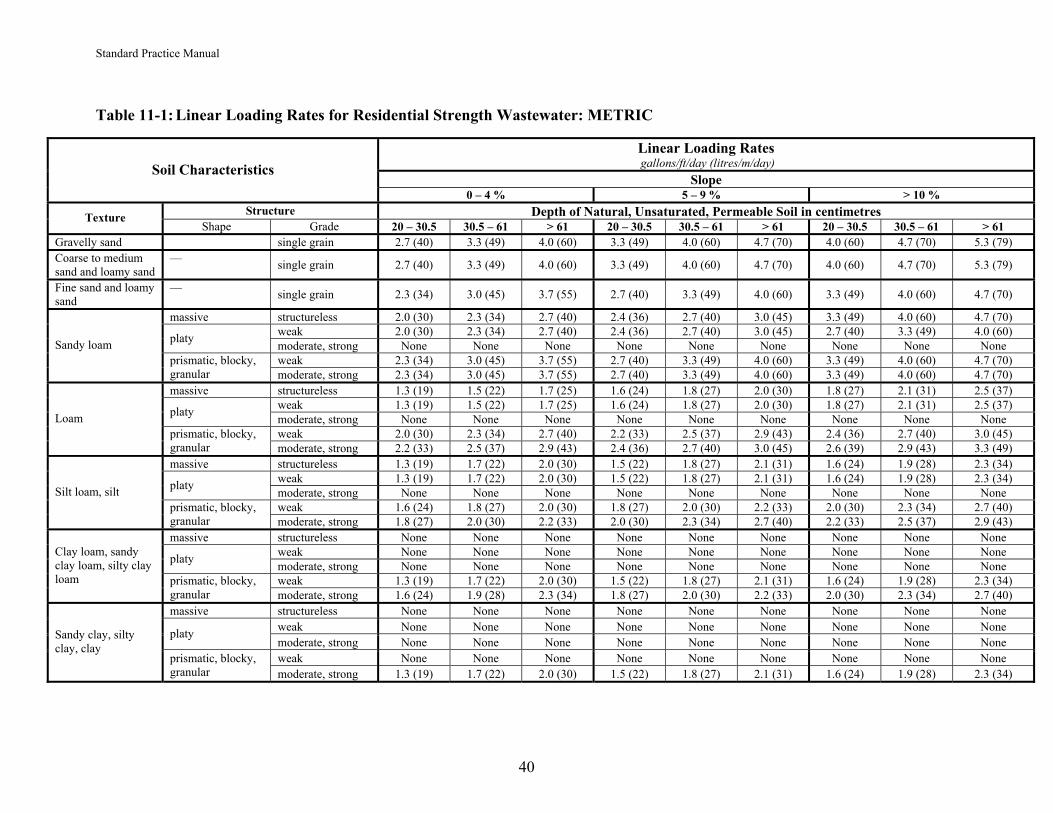
Standard Practice Manual
Table 11-1: Linear Loading Rates for Residential Strength Wastewater: METRIC
Linear Loading Rates gallons/ft/day (litres/m/day)
Slope Soil Characteristics
0 – 4 % 5 – 9 % > 10 % Structure Depth of Natural, Unsaturated, Permeable Soil in centimetres Texture
Shape Grade 20 – 30.5 30.5 – 61 > 61 20 – 30.5 30.5 – 61 > 61 20 – 30.5 30.5 – 61 > 61 Gravelly sand single grain 2.7 (40) 3.3 (49) 4.0 (60) 3.3 (49) 4.0 (60) 4.7 (70) 4.0 (60) 4.7 (70) 5.3 (79) Coarse to medium sand and loamy sand
— single grain 2.7 (40) 3.3 (49) 4.0 (60) 3.3 (49) 4.0 (60) 4.7 (70) 4.0 (60) 4.7 (70) 5.3 (79)
Fine sand and loamy sand
— single grain 2.3 (34) 3.0 (45) 3.7 (55) 2.7 (40) 3.3 (49) 4.0 (60) 3.3 (49) 4.0 (60) 4.7 (70)
massive structureless 2.0 (30) 2.3 (34) 2.7 (40) 2.4 (36) 2.7 (40) 3.0 (45) 3.3 (49) 4.0 (60) 4.7 (70) weak 2.0 (30) 2.3 (34) 2.7 (40) 2.4 (36) 2.7 (40) 3.0 (45) 2.7 (40) 3.3 (49) 4.0 (60) platy moderate, strong None None None None None None None None None weak 2.3 (34) 3.0 (45) 3.7 (55) 2.7 (40) 3.3 (49) 4.0 (60) 3.3 (49) 4.0 (60) 4.7 (70)
Sandy loam prismatic, blocky, granular moderate, strong 2.3 (34) 3.0 (45) 3.7 (55) 2.7 (40) 3.3 (49) 4.0 (60) 3.3 (49) 4.0 (60) 4.7 (70) massive structureless 1.3 (19) 1.5 (22) 1.7 (25) 1.6 (24) 1.8 (27) 2.0 (30) 1.8 (27) 2.1 (31) 2.5 (37)
weak 1.3 (19) 1.5 (22) 1.7 (25) 1.6 (24) 1.8 (27) 2.0 (30) 1.8 (27) 2.1 (31) 2.5 (37) platy moderate, strong None None None None None None None None None weak 2.0 (30) 2.3 (34) 2.7 (40) 2.2 (33) 2.5 (37) 2.9 (43) 2.4 (36) 2.7 (40) 3.0 (45)
Loam prismatic, blocky, granular moderate, strong 2.2 (33) 2.5 (37) 2.9 (43) 2.4 (36) 2.7 (40) 3.0 (45) 2.6 (39) 2.9 (43) 3.3 (49) massive structureless 1.3 (19) 1.7 (22) 2.0 (30) 1.5 (22) 1.8 (27) 2.1 (31) 1.6 (24) 1.9 (28) 2.3 (34)
weak 1.3 (19) 1.7 (22) 2.0 (30) 1.5 (22) 1.8 (27) 2.1 (31) 1.6 (24) 1.9 (28) 2.3 (34) platy moderate, strong None None None None None None None None None weak 1.6 (24) 1.8 (27) 2.0 (30) 1.8 (27) 2.0 (30) 2.2 (33) 2.0 (30) 2.3 (34) 2.7 (40)
Silt loam, silt prismatic, blocky, granular moderate, strong 1.8 (27) 2.0 (30) 2.2 (33) 2.0 (30) 2.3 (34) 2.7 (40) 2.2 (33) 2.5 (37) 2.9 (43) massive structureless None None None None None None None None None
weak None None None None None None None None None platy moderate, strong None None None None None None None None None weak 1.3 (19) 1.7 (22) 2.0 (30) 1.5 (22) 1.8 (27) 2.1 (31) 1.6 (24) 1.9 (28) 2.3 (34)
Clay loam, sandy clay loam, silty clay loam prismatic, blocky,
granular moderate, strong 1.6 (24) 1.9 (28) 2.3 (34) 1.8 (27) 2.0 (30) 2.2 (33) 2.0 (30) 2.3 (34) 2.7 (40) massive structureless None None None None None None None None None
weak None None None None None None None None None platy moderate, strong None None None None None None None None None weak None None None None None None None None None
Sandy clay, silty clay, clay
prismatic, blocky, granular moderate, strong 1.3 (19) 1.7 (22) 2.0 (30) 1.5 (22) 1.8 (27) 2.1 (31) 1.6 (24) 1.9 (28) 2.3 (34)
40

Linear Loading Rates gallons/ft/day (litres/m/day)
Slope Soil Characteristics
0 – 4 % 5 – 9 % > 10 % Structure Depth of Natural, Unsaturated, Permeable Soil in inches Texture
Shape Grade 8 – 12 12 – 24 > 24 8 – 12 12 – 24 > 24 8 – 12 12 – 24 > 24 Gravelly sand single grain 2.7 (40) 3.3 (49) 4.0 (60) 3.3 (49) 4.0 (60) 4.7 (70) 4.0 (60) 4.7 (70) 5.3 (79) Coarse to medium sand and loamy sand
— single grain 2.7 (40) 3.3 (49) 4.0 (60) 3.3 (49) 4.0 (60) 4.7 (70) 4.0 (60) 4.7 (70) 5.3 (79)
Fine sand and loamy sand
— single grain 2.3 (34) 3.0 (45) 3.7 (55) 2.7 (40) 3.3 (49) 4.0 (60) 3.3 (49) 4.0 (60) 4.7 (70)
massive structureless 2.0 (30) 2.3 (34) 2.7 (40) 2.4 (36) 2.7 (40) 3.0 (45) 3.3 (49) 4.0 (60) 4.7 (70) weak 2.0 (30) 2.3 (34) 2.7 (40) 2.4 (36) 2.7 (40) 3.0 (45) 2.7 (40) 3.3 (49) 4.0 (60) platy moderate, strong None None None None None None None None None weak 2.3 (34) 3.0 (45) 3.7 (55) 2.7 (40) 3.3 (49) 4.0 (60) 3.3 (49) 4.0 (60) 4.7 (70)
Sandy loam prismatic, blocky, granular moderate, strong 2.3 (34) 3.0 (45) 3.7 (55) 2.7 (40) 3.3 (49) 4.0 (60) 3.3 (49) 4.0 (60) 4.7 (70) massive structureless 1.3 (19) 1.5 (22) 1.7 (25) 1.6 (24) 1.8 (27) 2.0 (30) 1.8 (27) 2.1 (31) 2.5 (37)
weak 1.3 (19) 1.5 (22) 1.7 (25) 1.6 (24) 1.8 (27) 2.0 (30) 1.8 (27) 2.1 (31) 2.5 (37) platy moderate, strong None None None None None None None None None weak 2.0 (30) 2.3 (34) 2.7 (40) 2.2 (33) 2.5 (37) 2.9 (43) 2.4 (36) 2.7 (40) 3.0 (45)
Loam prismatic, blocky, granular moderate, strong 2.2 (33) 2.5 (37) 2.9 (43) 2.4 (36) 2.7 (40) 3.0 (45) 2.6 (39) 2.9 (43) 3.3 (49) massive structureless 1.3 (19) 1.7 (22) 2.0 (30) 1.5 (22) 1.8 (27) 2.1 (31) 1.6 (24) 1.9 (28) 2.3 (34)
weak 1.3 (19) 1.7 (22) 2.0 (30) 1.5 (22) 1.8 (27) 2.1 (31) 1.6 (24) 1.9 (28) 2.3 (34) platy moderate, strong None None None None None None None None None weak 1.6 (24) 1.8 (27) 2.0 (30) 1.8 (27) 2.0 (30) 2.2 (33) 2.0 (30) 2.3 (34) 2.7 (40)
Silt loam, silt prismatic, blocky, granular moderate, strong 1.8 (27) 2.0 (30) 2.2 (33) 2.0 (30) 2.3 (34) 2.7 (40) 2.2 (33) 2.5 (37) 2.9 (43) massive structureless None None None None None None None None None
weak None None None None None None None None None platy moderate, strong None None None None None None None None None weak 1.3 (19) 1.7 (22) 2.0 (30) 1.5 (22) 1.8 (27) 2.1 (31) 1.6 (24) 1.9 (28) 2.3 (34)
Clay loam, sandy clay loam, silty clay loam prismatic, blocky,
granular moderate, strong 1.6 (24) 1.9 (28) 2.3 (34) 1.8 (27) 2.0 (30) 2.2 (33) 2.0 (30) 2.3 (34) 2.7 (40) massive structureless None None None None None None None None None
weak None None None None None None None None None platy moderate, strong None None None None None None None None None weak None None None None None None None None None
Sandy clay, silty clay, clay
prismatic, blocky, granular moderate, strong 1.3 (19) 1.7 (22) 2.0 (30) 1.5 (22) 1.8 (27) 2.1 (31) 1.6 (24) 1.9 (28) 2.3 (34)
Table 11-1: Linear Loading Rates for Residential Strength Wastewater: IMPERIAL
41
Standard Practice Manual

Standard Practice Manual
11.5 Pressurized Effluent Conveyance
The pressurized conveyance system relies upon pump(s), to provide even distribution of effluent to the dispersal system. The pump can be housed within:
• the third chamber of a three-chamber septic tank; • an integrated chamber within a Type 2 or Type 3 treatment plant; and, • a separate pump tank.
The low-pressure distribution process can control the effluent volume application rate by using either:
• an on-demand pump dosing system where pump activation will be controlled by wide angle single load rated float switch or by wide angle differential level low amp rated float switches connected to a relay housed in a watertight control box; or,
• a timed application rate pump activation will be controlled by narrow angle low amp float switches connected to a timer relay housed within a watertight control panel.
Timed application provides greater control of the dosing volume and dosing intervals.
11.5.1 Pump Tank The pump tank will be preceded by a primary pre-treatment (septic) tank equipped with an effluent filter or another form of treatment process (Type 2 or 3) prior to discharging effluent into the pump tank.
The pump tank will be structurally sound and watertight and constructed of corrosion-resistant material such as concrete or polymer based material and must comply with current CSA standards.
The pump tank must have an access lid at surface grade level.
Access lid to be not < 60 cm (2 ft.) in diameter and ensure a watertight and gastight fit.
To increase safety and prevent unauthorized or accidental entry into a pump tank, access openings must have a secure lid or cover. Acceptable protective lid features include but are not limited to:
• a padlock; • a cover that can only be removed with tools; or, • a cover having a minimum weight of 29.5 kilograms (65 pounds).
and have bevelled edges to prevent the cover from falling into the riser or tank.
Polymer-based material to have a UV8 minimum protection rating.
11.5.2 Pump Tank Sizing The type of pumping configuration that will be used determines tank sizing:
• Tank volume to provide 75% of daily flow rate above pump off level and 15% daily flow reserve volume above pump tank high level alarm’s on position.
• Demand activation volume = 1 day design flow rate.
42

Standard Practice Manual
Minimum capacity 1,600 L (350 gallons). • Timed activation volume = 2 times the daily flow.
Minimum rate capacity 3,400L (750 gallons).
This standard does not apply to pump tanks integrated into Type 2 or Type 3 treatment plants.
11.5.3 Effluent Pump All pumps to comply with CSA and UL standards.
Be rated for the specific application.
Have non-corrosive impeller(s).
Pump inlet to be elevated at a minimum 20 cm (8") above the pump tank floor.
The elevation method must provide stable support and not obstruct the inlet.
11.5.4 Plumbing Criteria All pipe work to follow British Columbia Plumbing Code practices
Conveyance piping materials must:
• conform with CSA standards or certified by a recognized testing agency accepted by the Standards Council of Canada, as meeting or exceed the requirements of the appropriate CSA standard for its intended use;
• have a shutoff valve on the transport pipe;
• have a check valve installed to prevent drain back of effluent between doses unless system is installed in cold climate areas as drainage of the supply pipe may be required to prevent freezing;
• be equipped with unions for quick disconnection for removal 15 cm (6") below the access lid. (Union is to be positioned at the top of the pump assembly on the pump side of the check shutoff and valve and be accessible at grade);
• be equipped with a vacuum breaker or other method to prevent siphoning of tank contents if the supply pipe is situated at a higher elevation than the effluent discharge point; and
• have a pump removal assembly. Removal assembly is to be designed to remove pump efficiently and safely and have corrosion resistant fittings.
11.5.5 Electrical Criteria Electrical wiring must comply with BC Electrical Codes for wet and corrosive locations for all new installations. In the case of repair, wiring must be installed based on good practice.
Electrical work must be performed or inspected by a registered class C electrician or equivalent technician.
43

Standard Practice Manual
Power supply entry through riser or tank must be gastight and watertight.
Electrical connection boxes and control panel must be positioned for easy access, maintenance and adjustment requirements.
Control panel boxes to be a NEMA 4X or equivalent.
Control panel to be equipped with cycle counters and elapsed time metres.
11.5.6 Float Switch Criteria Float switches will be mounted on a separate bracket or float tree so that they can be easily replaced and/or adjusted without removing the pump.
The float switch must be equipped with a high liquid level alarm that is both audible and visual. The alarm must be:
• placed in a conspicuous location; • audible so as to be heard within a 30 metre (100 ft.) radius; • wired separately from the pump; and, • powered by a dedicated power supply.
11.5.7 Effluent Pump Filtration Pumps must be fitted with filters to prevent field clogging. Filters must filter out particles > 2 mm (1⁄16")
11.5.8 Inspection, Monitoring and Maintenance All monitoring, inspection and maintenance is to be performed by an Authorized Person
Inspect all electrical connections • Ensure that high level or other alarm(s) are in working order • Ensure that float switches are performing properly
Inspect control panel box for watertightness • Ensure that timer or control relays are functioning
Inspect float levels
Inspect all plumbing fittings and connections
Ensure that all components are operating as per design
The pressurized conveyance system, shown in Figure 11-2, relies on pump(s), to provide even distribution of effluent to the distribution system.
44

Standard Practice Manual
Figure 11-3: Pressure distribution system
11.6 Pressure Distribution Construction
The pressure distribution network is the method that distributes effluent the most uniformly throughout the soil absorption system. It does this by using a pump or siphon to pressurize small diameter pipes with small diameter orifices that are spaced out evenly across the entire absorption system. With each pressurized dose of effluent, it is spread out evenly among all of the orifices, and therefore also to the soil.
Pressure distribution is also used in the design of mound systems.
The design of pressure distribution network systems is described in Appendix E.
11.7 Low-Pressure Effluent Distribution
The Authorized Person will:
• Determine total daily flow rate from the facility using table 4-1 or 4-2 • Determine the distribution field size required using hydraulic loading rates table 5-3 • Use pressure systems for distribution areas exceeding 152 lineal meters 60 cm wide
trench (500 lineal feet/ 2 foot wide trench) or for distribution systems greater than 93 sq/meters (1000 sq/ft)
• Determine the total dynamic head pressure • Determine the flow application rate • Determine the distribution discharge orifice size and spacing • Provide detailed technical and distribution system layout plans • Perform a comprehensive test of all components and distribution pressure test to verify
that the distribution system is in proper working order prior to final backfilling, grading and placing into operation
11.7.1 Design Criteria Pre-treated to a Type 1 effluent quality with particulate filtration of not < 2 mm (1⁄16") prior to discharge.
Flow velocity to be not less than 60 cm (2 ft.) per second.
45

Standard Practice Manual
Residual head height variation from proximal to distal end of pipe must be not greater than 10%.
Residual head height at distribution orifice must be no less than 60 cm (2 ft.).
Orifice spacing must not be less than 60 cm (2 ft.).
Orifice diameter must not be less 5 mm (3⁄16").
Each orifice to be protected with an orifice shield: • To be applied to both crown and invert orifice orientation to prevent excess soil
erosion from effluent pressure.
Lateral spacing: • Not less than 90 cm (3 ft.) for bed; and, • Not less than 1.8 cm (6 ft.) for trench.
Lateral diameter not less than 3 cm (1.25") and not greater than 5 cm (2").
All laterals must be provided with an accessible cleanout access: • Cleanout end to be equipped with a screw cap or plug fitting; and, • Cleanout must be accessible from grade.
The last lateral orifice must be located not less than 60 cm (2 ft.) from cleanout.
The first lateral orifice must not be located less than 60 cm (2 ft.) from distribution manifold connection.
11.7.2 Orifice Orientation Crown orifice orientation (12 o’clock) provides quickest pressurization of system.
Invert orifice orientation (6 o’clock) will require distal end air orifice at crown orientation to bleed air and prevent pump failure.
Laterals will drain in invert orientation which may be beneficial in cold climates.
11.7.3 Distribution Sizing Sizing will be determined by:
• Daily wastewater flow rate; • The soil effluent loading rate; • Professional supervision of construction required when:
(1) slope is greater than 15%, or (2) site constraints is a Class 4 on table 5-1 include linear loading rate under either of these conditions; and,
• Dosing criteria.
Dosing volume to be 5 to 7 times the pipe volume of the laterals or 20% of daily flow rate but is not to exceed the daily hydraulic loading rate as determined by Table 5-3.
Residual head height at distribution orifice must be no less than 60 cm (2 ft.)
46

Standard Practice Manual
Orifice diameter must not be less 5 mm (3⁄16")
11.7.4 Pressure Test Perform a residual head pressure test to verify proper residual head height.
Residual head height variation from proximal to distal end of pipe must be not greater than 10%.
11.7.5 Maintenance • Periodic clean out of laterals • Residual pressure test • Dosing application rate and volume test
11.7.6 Cold Weather Criteria In cold climate area, protect all piping and water filled components from freezing.
Orient laterals so that effluent drains out after the dosing period.
12 SEEPAGE BEDS
12.1.1 Site Criteria Soil texture must be coarse sand, fine sand, loamy sand, silty sand or sandy loam.
Slope must be less than 15%. Sites not meeting this criteria require design and supervision by a Professional.
12.1.2 Construction Criteria Pressure distribution criteria recommended for seepage beds.
Bed must be level across its width and length, be constructed perpendicular to the slope and must be as long and narrow as possible. No more than three laterals must be used.
The bed must have not less than 15 cm (6") of aggregate depth between point of discharge and bed bottom infiltration area and must have a 5 cm (2") aggregate cover above distribution pipe.
For monitoring, the bed must be equipped with a minimum of two effluent infiltration monitoring wells located at proximal and distal ends of the bottom lateral run.
The aggregate must be covered with a non-biodegradable, breathable geotextile material or equivalent (building paper) and must have a soil cover of not less than 15 cm (6").
The sites must be graded to provide drainage away from bed surface area.
Seed or sod the site immediately after construction to prevent erosion.
47

Standard Practice Manual
12.1.3 Bed Sizing Bed infiltrative bottom area required = Daily wastewater flow rate divided by hydraulic loading rate:
Table 4-1 or 4-2 ÷ HLR Table 5-3
Infiltrative area = daily sewage flow divided by hydraulic loading rate X 1.35
Length of bed = infiltrative area divided by bed width
12.1.4 Bed Dimensions Must be not greater than 4 metres (13 ft.) in width and 30 m (100 ft.) length.
The discharge lateral spacing must not be less than 90 cm (3 ft.) and not greater than 120 cm (4 ft.).
The beds outer edge must not be less than 45 cm from centre of discharge lateral pipe.
12.2 Aggregate (Drain Rock) Criteria
Aggregate media specifications:
• Aggregate must be non-biodegradable. (Concrete rubble is not an acceptable aggregate).
• Effective size range from 2 cm (⅓") to 5 cm (2") • All aggregate must be washed and screened and contain less than 5% fines, silt or clay
coating.
12.3 Construction
All work must be done when soil moisture conditions will not adversely affect soil structure and hydraulic conductivity, the site is dry, and compaction from machinery will not cause significant damage to the distribution area.
The bed must be constructed in a manner that does not compromise the original soil structure by smearing or compacting the soil surface.
• Any smearing or compaction that does occur will need to be repaired by scarifying or tilling the surface of the distribution area.
Finished distribution area to be graded so that rain or ground water can drain away from the site.
• Seed or sod the site immediately after construction to prevent erosion.
48

Standard Practice Manual
Figure 11-4: Bed pressure dispersal layout
Geotextile cover
Clean 2 to 5 cmaggregate
30 cm
15 - 30 cm
Monitoringwell
120 cm
60 cm
90 cm Discharge lateral
45 cm
3 meters
60 cm
13 MOUNDS
The mound is an above-grade soil absorption system used for wastewater treatment and dispersal. The mound system consists of a septic tank, a dosing chamber and the mound itself. The principal features of the mound are a gravel or aggregate layer for distribution of the wastewater, a layer of special sand imported to the site, and a layer of the native, permeable, unsaturated soil on the site.
The construction of the system depends on wastewater characteristics, siting requirements, loading rates and sizing.
The design of mound systems is described in Appendix F.
13.1 Site Criteria
The Authorized Person will:
• Determine total daily flow rate from the facility using table 4-1 or 4-2. • Determine the distribution field size required using hydraulic loading rates Table 5-3. • Use pressure systems for all mound distribution systems • Determine the total dynamic head pressure • Determine the flow application rate • Determine the distribution discharge orifice size and spacing • Provide detailed technical and distribution system layout plans • Perform a comprehensive test of all components and distribution pressure test to verify
that the distribution system is in proper working order prior to final backfilling, grading and placing into operation
13.2 Construction Criteria
A low-pressure distribution system must be used to disperse effluent for every mound system. See section 11 for pressure distribution criteria.
49

Standard Practice Manual
Mounds may be constructed using trench construction standards (section 10) or bed construction standards (section 12).
• Trench or bed can use aggregate, synthetic aggregate or chamber process.
Mounds must have a maximum height of 1m (3.33 ft.) with minimum vertical separation as outlined in Table 5-2, be constructed perpendicular to the slope, following contour and must be long and narrow.
The distribution basal area must be level along length and width of the mound with the berm side slope is to beginning not less than 1 metre from outer edge of distribution lateral.
Berm side slope must be greater than 3:1 horizontal to vertical ratio.
Provide for an effluent infiltrative monitoring well and a down-gradient effluent sampling monitoring well.
13.3 Fill Material Specifications
Fill material is to conform to ASTM C-33 standards and must meet the requirements of the following Table 13-1 (Mound Sand Particle Sizing Criteria).
Table 13-1: Mound sand particle sizing criteria Sieve Effective Particle Size % Passing
No. 4 4.75 mm 95 –100% No. 8 2.36 mm 80 –100% No. 16 1.18 mm 50 – 85% No. 30 0.6 mm 25 – 60% No. 50 0.3 mm 10 – 30% No. 100 0.15 mm 2 – 10% No. 200 0.075 mm < 3 %
13.4 Mound Sizing
Sizing of the mound must be determined by the hydraulic loading rates outlined in Table 5-3
13.5 Construction
All work must be done when soil moisture conditions will not adversely affect soil structure and hydraulic conductivity, the site is dry, and compaction from machinery will not cause significant damage to the distribution area.
The mound must be constructed in a manner that does not compromise the original soil structure by smearing or compacting of soil surface
50

Standard Practice Manual
• Any smearing or compacting that does occur will need to be repaired by scarifying or tilling the surface of the distribution area
Soil must be prepared by ploughing surface to a depth of not less than 15 cm (6").
Mound sand fill placement must begin shortly after basal area is prepared.
Finished distribution area must be graded so that rain or ground water can drain away from the site.
• Seed or sod the site immediately after construction to prevent erosion.
13.6 Inspection, Monitoring and Maintenance
Periodically inspect the effluent infiltration monitoring well.
Periodically sample effluent from down-gradient monitoring/sampling well.
14 GRAVELLESS AGGREGATE EFFLUENT DISPERSAL SYSTEMS Gravelless systems or artificial aggregate systems offer alternatives to traditional pipe and gravel distribution. The use of gravelless technology has advantages in areas where aggregate is unavailable or very expensive; additionally these technologies may reduce installation costs.
14.1 Proprietary Gravelless Systems
Proprietary gravelless systems will be: • sized according to the soil effluent loading and hydraulic loading rates (Table 5-3); • have a load bearing capacity not less than AASHTO H-10; • must be installed with consideration to manufacturer’s instructions; and, • chamber systems must have an effective side wall open area not less than 35% of
bottom infiltrative area.
Synthetic aggregate system must: • provide not less than the equivalent void space as a gravel aggregate system (not less
than 35% void space); and, • withstand the pressure of backfill without distortion or compaction.
15 SLOPING SITES Sloping sites present a unique challenge for system construction. Poorly constructed or installed systems on sloping sites will be more likely to fail. The primary problem relates to the improper measurement of vertical separation and inappropriate horizontal spacing between trenches.
51

Standard Practice Manual
15.1 Slope Construction
Maintain proper unsaturated vertical separation when constructing bed or trench type dispersal systems on sloping terrain in accordance with Table 5-2.
As slope increases ensure proper spacing between trenches. Slopes greater than 15% require 3 m (10 ft.) horizontal separation between trenches.
To determine depth of trench walls on a sloped site use figure 15-1 as follows: • Determine trench width and slope percentage across width (depth C) • Determine depth required for aggregate, pipe and cover (depth B) • Add depth B + depth C to get depth A
Can be applied to bed dispersal method as well (Bed slope less than 15%)
Figure 15-1: Trench depth variance on sloped site
width
depth A
depth B
depth C30
cm
16 LAGOONS
16.1 General
The lagoon system is a method of sewage disposal. The system consists of a septic tank and one or multiple lagoon cells. The lagoon cell itself is a large and generally rectangular excavation surrounded by a berm. The berm is made by compacting the material excavated from inside the lagoon around its outer edges. Its function is to prevent surface water from entering the cell and overloading it. There must also be a fence on top of the berm to prevent entry into the lagoon area.
Lagoons function as infiltration basins and evaporation ponds. A properly designed and sized lagoon provides enough volume to allow for the retention of effluent long enough to allow for the fluid to enter high porosity soil and enough surface area for evaporation to take place. In areas suitable for lagoons it is assumed that 60 percent of effluent is evaporated.
52

Standard Practice Manual
16.2 Siting Criteria
The Authorized Person will determine the number of test pits to be excavated. The minimum acceptable number of test pits is two soil observation test pits and three percolation or hydraulic conductivity test pits. The test pits must:
Conform to the ‘Workers Compensation Act Occupational Health and Safety Regulation’, and be of a depth at least 1.0 metre (3 ft.) below the bottom of the proposed lagoon (i.e., 3.0 metres (10 ft.) deep for a 2.0 metre (6 ft.) deep lagoon).
The AP must then determine the unsaturated vertical separation, percolation or the soil hydraulic conductivity and the surface grade.
A lagoon system requires a site that has in addition to the requirements outlined in Table 5-1 and 5-3: • A minimum area of 4.0 acres; • A minimum unsaturated vertical depth from the bottom of the lagoon of 1 metres (3.33
feet); • A minimum unsaturated vertical depth from the native soil surface of 3 metres (10 feet); • A soil percolation rate of at least 60 minutes/2.5 cm (1 inch); and, A slope no greater than 12%A lagoon system can be constructed on a site not meeting these requirements if designed and constructed under the supervision of a Professional.
Lagoons should be constructed in open areas able to take advantage of airflow to facilitate evaporation.
16.3 Construction Criteria
Septic tanks may be used as a pre-treatment for lagoons. Effluent to the lagoon must be at least of Type 1 quality and be preceded by an appropriate septic tank. Septic tanks are used on lagoon systems to prevent solids from clogging the basel area of the lagoon reducing infiltration and to reduce fat oils and greases, which mask the lagoon surface decreasing evaporation.
For the purpose of lagoon design septic tank sizing is determined using two times daily sewage flow calculated by using Table 4-1 or 4-2. Common tank sizing is found in Table 16-1.
Table 16-1 Minimum Septic Tank Sizing for Lagoon Systems
Daily Sewage Flow Litres (gallons) Septic Tank Sizes Litres (gallons)
1,136 L/ (250 gal) 2,272 L/ (500 gal)
1,363 L/(300 gal) 2,726 L/ (600 gal)
1,700 L/ (375 gal) 3,400 L/ (750 gal)
2,045 L/(450 gal) 4,090 L/ (900 gal)
53

Standard Practice Manual
2,500 L/ (550 gal) 5,000 L/ (1,100 gal)
Effluent may be discharged into the lagoon either by gravity or by pump.
All piping, and fittings must comply with Section 6, and pumps must comply with section 11 CSA and UL standards.
The piping is to be buried sufficiently to prevent freezing and be installed with “Y” style cleanout at least every 15 m (50 ft.).
16.3.1 Gravity Flow Discharge For gravity flow discharge into the lagoon, the septic tank outlet must be higher than the top of the berm to prevent backflow. The difference in elevation between the septic tank outlet and the berm must be at least 45 cm (18").
The minimum required slopes for sewer lines are: • 1% for a 10 cm (3'') pipe and • 2% for a 7.5 cm (2.5'') pipe.
The sewer pipe must: • extend a minimum of 2 metres (6 ft.) into the lagoon from the nearest inside wall; • direct effluent horizontally to the centre of the lagoon; and, • be positioned securely 30 cm (1 ft.) above the lagoon bottom.
Pipe cleanouts are required in the sewer lines and must be: • no greater than 15 metres (50 ft.) apart; • attached to the sewer line with a sanitary tee or “Y” with a 45º fitting; • have cleanout caps equipped with cleanout fitting and screw type plug; and, • cleanout caps must be accessible at the surface grade level.
16.3.2 Pumped Discharge For discharge pumped into the lagoon, the pump must be designed to maintain a minimum flow velocity of 70 cm/second (2.5 ft/second) through the sewer pipe.
The discharge must be pumped from a separate pump tank or separate pump chamber:
The sewer pipe must:
• be fitted with a backflow prevention device that prevent sewage from entering the building;
• be positioned near the centre of the lagoon; • be a minimum of 2 metres into the lagoon from the nearest inside wall; • be securely anchored to the lagoon bottom; and, • direct influent vertically to the centre of the lagoon.
54

Standard Practice Manual
16.3.3 Lagoon Sizing The sizing of a lagoon is dependent on the water balance throughout the year of precipitation, evaporation and soil infiltration. The following minimum sizing requirements are required for lagoons in areas with positive evaporation potentials.
Lagoons must contain one year daily sewage flow and a minimum surface area to facilitate evaporation. Lagoons constructed to contain flows exceeding those outlined in tables 16-2 and 16-3 shall be sized using the following formula:
Volume of a rectangular lagoon (frustum pyramid) = 1/3h(A1 + A2 + √A1A2 ) where h is height, A1 is area of the top and A2 is area of the bottom
Volume of a circular lagoon (cone) = 1/3 Pi R2 h where R is the radius and h is the height ,Pi = ~ 3.14
Surface area = 0.66 x volume in cubic meters
Volume and surface area calculator for cones and frustum pyramids may be found at:
www.webcalc.net/menu.php
Sizing criteria for lagoons are shown in Table 16-1
Table 16-2: Rectangular Lagoon cell sizing requirements Volume Depth Metres
(feet) Total Surface Area Bedrooms Estimated
Design Flow (Litres/Gallons) Cubic
Meters (Cubic Ft.)
Meters (feet)
Bottom Inside
Top Inside
Square metres
(square feet)
1-2 1,136 L/250 gal 416 (14,951)
2 (6.5)
14 x 4m (47 x 13
ft.)
26 x 16m (87 x 53
ft.)
416 sq.m 4,611sq.ft.
3 1,363 L/300 gal 500 (18,172)
2 (6.5)
16 x 5m (53 x 17
ft.)
28 x 17m (93 x 57
ft.)
476 sq. m
5,301sq.ft. 4 1,700 L/375 gal 639
(23,168)2
(6.5) 20 x 6m (67 x 20
ft.)
32 x 18m (107 x 60
ft.)
576 sq. m
6,420sq.ft. 5 2,045 L/450 gal 746
(26,553)2
(6.5) 22 x 7m (73 x 23
ft.)
34 x 19m (113 x 63
ft.)
646 sq. m
7,119sq.ft. 6 2,500 L/550 gal 917
(33,128)2
(6.5) 24 x 9m (80 x 30
ft.)
36 x 21m (120 x 70
ft.)
756 sq. m
8,400sq.ft.
55

Standard Practice Manual
Table 16-3: Circular Lagoon cell sizing requirements Volume Depth Diameter Total
Surface Area
Bedrooms Estimated Design Flow
(Litres/Gallons) Cubic Meters (Cubic Ft.)
Meters (feet)
Metres (feet) Square metres
(square feet)
1-2 1,136 L/250 gal 506 (17,643)
4 (13)
22m (72 ft.)
380sq.m 4,090sq.ft.
3 1,363 L/300 gal 553 (19,144)
4 (13)
23m (75 ft.)
415 sq. m 5,113sq.ft.
4 1,700 L/375 gal 654 (22,884)
4 (13)
25m (82ft.)
490 sq. m
5,274sq.ft. 5 2,045 L/450 gal 763
(26,355)4
(13) 27m
(88 ft.)
572 sq. m 6,157sq.ft.
6 2,500 L/550 gal 911 (32,022)
4 (13)
29.5m (97 ft.)
683 sq. m
7,352sq.ft. The dimensions in table 16-2 and 16-3 are based on the interior sidewalls having a horizontal slope of 2 to a vertical slope of 1. (2:1 slope).
On properties where the lagoon dimension requirements of table 16-2 or 16-3 cannot be met, variations to the dimensions may be possible provided that the total surface area and volume requirements can be met.
16.3.4 Construction Lagoons must be oriented along the surface contours in order to reduce slope variation.
A lagoon must include the following vertical dimensions: • have a minimum one year retention of the design sewage flow as determined by Table
4-1 or 4-2; • the lagoon bottom is in accordance with Tables 16-2 and 16- 3 below surface level; • the berm is 0.9 to 1.5 metres (3-5 ft.) tall; • the allowable freeboard (height remaining between the lagoon surface and the top of
the berm) is a minimum of 0.6 metres(2 ft.); and, • the vertical separation distance, as described in Section 5.5, is of at least 1.0 metre
(3 ft.). On sloped sites the berm may be constructed partially in grade; however, the berm on the lower side must not exceed 1.5 metres (5 ft.) unless the design and construction is supervised by a Professional.
56

Standard Practice Manual
The berm must be constructed so that: • the slopes of the sidewalls are: • 2:1 for inside walls; and, • a minimum of 3:1 for outside walls; • the top of the berm must be no less than 1.2 metres (4 ft.) in width when fencing is
placed on the top of the berm; • the clay soil making up the berm must be well compacted in 30 cm (1 ft.) lifts and
void of all topsoils and organics.
Freezing potential is greatly reduced by the construction of an internal berm, which increases the depth of water over the pipe and insulates it. The internal berm should be:
• situated ⅓ of the distance along the length of the lagoon; and, • 1.2 metres (4 ft.) in height.
Surface drainage must be directed away from the base of the berm.
16.3.5 Fencing A fence must be built so that:
• it completely encloses the lagoon area; • it is 1.2 metres (4 ft.) tall; and, • access is provided from one side.
16.4 Installation Standards
Lagoons must not be located within the setback distances laid out in Table 5-1.
16.5 Maintenance
Required maintenance of a lagoon system includes: • maintaining the septic tank as per Section 17; • ensuring that the effluent pump and controls are in adequate operating condition by: • measuring the draw of the pump when engaged; and, • checking all electrical connections; • checking all plumbing fittings and ensure that piping is in operating condition; • assessing structural integrity of polymer based access lids; • maintaining fencing; and controlling vegetation growth
57

Standard Practice Manual
17 MAINTENANCE AND INSPECTION
17.1 Requirements of the Sewerage System Regulation
17.1.1 Owner Section 10 of the Sewerage System Regulation requires that an owner ensure that a sewerage system on the owner’s land is maintained in accordance with the maintenance plan provided in respect of the sewerage system.
In addition the owner must keep records of maintenance carried out according to the maintenance plan.
17.1.2 Maintenance Provider Section 12 of the Regulation indicates that a person commits an offence if the person maintains a sewerage system without proper qualifications, i.e., without being an Authorized Person.
The Authorized Person must prepare a maintenance plan for the owner/operator.
To determine whether the maintenance plan is consistent with standard practice, the AP may have regard to the Standard Practice Manual. (Section 9).
The maintenance plan must be submitted with a letter of certification, indicating that if operated and maintained as set out in the maintenance plan, the sewerage system will not cause or contribute to a health hazard. (Section 9(1) (b)).
An Authorized Person who makes a repair or alteration to a sewerage system must provide the owner with an amendment to the maintenance plan if:
• the work is not already covered by the filing of the sewerage system with the Health Authority; and,
• the maintenance plan provided as part of the letter of certification is, if followed, no longer sufficient to ensure that the sewerage system does not cause, or contribute to, a health hazard.
17.2 Maintenance Plan
The Authorized Person must prepare the maintenance plan so that it provides the user/operator and the service person with information about the system necessary to operate and maintain it. The user/operator and the service person should be able to follow the line of reasoning used when the system was designed.
The maintenance plan must include design and measured performance data for equipment installed, timer settings, draw-down depths, litres per cm of tank and actual pump delivery (L/min). The maintenance plan must explain the assumptions made to establish the design parameters and must include the following:
• a list of system “Do’s and Don’ts”,
58

Standard Practice Manual
• a list of relevant contacts related to system components and ongoing operations, • an emergency number to call, and • a list of the responsibilities of the user/operator.
17.3 Frequency of Inspection and Maintenance
The frequency of inspection of treatment and disposal systems depends on of the level of treatment.
Septic tanks must be pumped regularly to ensure proper functioning. If the septic system is not pumped in a timely manner, solids will build up, bypass the effluent tee or baffle and clog the soil absorption system — eventually resulting in hydraulic failure (i.e., plumbing backup and wastewater appearing on the ground surface).
The following table indicates the typical frequency of pump-out based on the number of residents and the volume of the septic tank.
The table is consistent with the literature and with typical service schedules set by suppliers of Type 2 systems, establishing a level of service for certified practitioners in a competitive environment. As this applies only to new installations or repairs, local government is encouraged to establish onsite system maintenance and monitoring programs as described in “Toolkit for the Development of Management Programs for On-Site Sewage Systems”. 2003. Environment Canada Georgia Basin Ecosystem Initiative.
Table 17-1: Inspection frequencies Component of the System Inspection Frequency Type 1 treatment system with gravity flow 3 years (pump out as necessary, when
60 % of liquid depth is sludge and scum. See table 17-2 below)
Type 2 and 3 treatment systems (i.e., aerobic treatment units (ATUs), intermittent sand filters, re-circulating gravel filters, attached growth systems)
3 months (pump out ATUs when 6,000 mg/L TSS in aeration tank or <10% clear zone in 30 min settling test)
Pressure distribution systems for Types 1, 2 or 3 6 months after start-up, then yearly
59

Standard Practice Manual
Table 17-2: Estimated septic tank pumping frequencies in years
Household Occupancy (Number of People) Tank Volume Litres
Tank Volume
(Imp. Gal.) 2 4 6 8 10 12
2,300 500 8.0 2.9 1.6 1.0 0.7 0.6 2,700 600 10.5 3.7 2.1 1.3 1.0 0.7 3,405 750 14.6 5.2 2.9 1.9 1.3 1.0 4,100 900 6.8 3.7 2.4 1.8 1.3 4,500 1,000 8.0 4.4 2.9 2.1 1.6 5,000 1,100 9.2 5.0 3.3 2.4 1.8 5,900 1,300 11.8 6.5 4.2 3.0 2.3 6,800 1,500 8.0 5.2 3.7 2.9 7,300 1,600 8.8 5.7 4.1 3.1
Frequency years
• For year-round residences • Based on accumulation rates from Bounds (1988) • Entries above thick line show septic tanks that do not meet minimum septic tank
volume requirements of the Standard Practice Manual assuming 2 occupants per bedroom.
17.4 Flow Trials
The flow trial is one technique that may be used to assess the capacity of a disposal system (i.e., soil absorption system). A flow trial should be carried out by a Registered Practitioner or Professional and should be preceded by a thorough inspection of the system, including the septic tank. The system should be in good working order. Further discussion on flow trials is in Appendix G.
60

Standard Practice Manual
Appendix A: Sewerage System Regulation
B.C. Reg. 326/2004 O.C. 701/2004
Deposited July 8, 2004effective May 31, 2005
Health Act
SEWERAGE SYSTEM REGULATION
Contents Part 1 — Definitions and General Rules 1 Definitions 2 Application 3 Discharge of domestic sewagePart 2 — Holding Tanks 4 Permit for holding tank 5 Maintenance of holding tankPart 3 — Sewerage Systems 6 Restriction on construction and maintenance 7 Authorized persons 8 Filing 9 Letter of certification 10 Maintenance of sewerage systemPart 4 — Enforcement 11 Inspections and orders 12 Offences
Part 1 — Definitions and General Rules
Definitions 1 In this regulation:
“Act” means the Health Act;
“authorized person” means a registered practitioner or a professional;
“construct” includes
(a) to plan or conduct a site assessment in respect of a sewerage system,
B-1

Standard Practice Manual
(b) to install, repair or alter a sewerage system, and
(c) in the case of a professional, to supervise the doing of any matter listed in paragraphs (a) and (b);
“discharge area” means an area used to receive effluent discharged from a treatment method;
“domestic sewage” includes
(a) human excreta, and
(b) waterborne waste from the preparation and consumption of food and drink, dishwashing, bathing, showering, and general household cleaning and laundry, except waterborne waste from a self-service laundromat;
“effluent” means domestic sewage that has been treated by a treatment method and discharged into a discharge area;
“health authority” means the regional health board established under the Health Authorities Act that has jurisdiction over the geographic area in which a sewerage system is located;
“health hazard” includes
(a) the discharge of domestic sewage or effluent into
(i) a source of drinking water, as defined by the Drinking Water Protection Act,
(ii) surface water,
(iii) tidal waters, or
(iv) a sewerage system that, in the opinion of an inspector, is not capable of containing or treating domestic sewage, and
(b) the discharge of domestic sewage or effluent onto land;
“holding tank” means a watertight container for holding domestic sewage until the domestic sewage is removed for treatment;
“inspector” means a medical health officer or a public health inspector;
“maintenance”, in the case of a professional, includes to supervise the maintenance of a sewerage system;
“maintenance plan” means a set of instructions for maintaining a sewerage system that, if followed, will ensure that the sewerage system does not cause, or contribute to, a health hazard;
“owner”, in respect of land on which a sewerage system or holding tank is, or is required to be, constructed under this regulation, includes
(a) a person registered in the land title records as the owner of the land, whether entitled to the land in the person's own right, in a representative capacity or otherwise,
B-2

Standard Practice Manual
(b) a lessee or a person holding a licence to occupy the land, and
(c) if a sewerage system or holding tank serves more than one parcel, strata lot or shared interest, the strata corporation or other corporate entity that developed the parcels, strata lot or shared interest, as applicable;
“parcel” means any lot, block or other area in which land is held or into which it is subdivided, but does not include land covered by water;
“professional” means a person who meets the requirements of section 7 (3) [authorized persons];
“registered practitioner” means a person who is qualified to act as a registered practitioner under section 7 (1) or (2);
“registration certificate” means a registration certificate issued by the Applied Science Technologists and Technicians of British Columbia that certifies that the holder is competent to construct and maintain a sewerage system that uses a treatment method classified as Type 1 or Type 2;
“septic tank” means a watertight container for receiving, treating and settling domestic sewage;
“sewerage system” means a system for treating domestic sewage that uses one or more treatment methods and a discharge area, but does not include a holding tank or a privy;
“shared interest” means a shared interest in land as defined in the Real Estate Development Marketing Act;
“standard practice” means a method of constructing and maintaining a sewerage system that will ensure that the sewerage system does not cause, or contribute to, a health hazard;
“strata lot” means a strata lot as defined in the Strata Property Act;
“surface water” means a natural watercourse or source of fresh water, whether usually containing water or not, and includes
(a) a lake, river, creek, spring, ravine, stream, swamp, gulch and brook, and
(b) a ditch into which a natural watercourse or source of fresh water has been diverted,
but does not include ground water or water in a culvert that is constructed to prevent the contamination of a watercourse by domestic sewage or effluent;
“treatment method” means a treatment method for domestic sewage classified as Type 1, Type 2 or Type 3 where
(a) Type 1 is treatment by septic tank only,
(b) Type 2 is treatment that produces an effluent consistently containing less than 45 mg/L of total suspended solids and having a 5 day biochemical oxygen demand of less than 45 mg/L, and
B-3

Standard Practice Manual
(c) Type 3 is treatment that produces an effluent consistently containing less than 10 mg/L of total suspended solids and having
(i) a 5 day biochemical oxygen demand of less than 10 mg/L, and
(ii) a median fecal coliform density of less than 400 Colony Forming Units per 100 mL.
Application 2 This regulation applies to the construction and maintenance of
(a) a holding tank,
(b) a sewerage system that serves a single family residence or a duplex,
(c) a sewerage system or combination of sewerage systems with a combined design daily domestic sewage flow of less than 22 700 litres that serves structures on a single parcel, and
(d) a combination of sewerage systems with a combined design daily domestic sewage flow of less than 22 700 litres that serves structures on one or more parcels or strata lots or on a shared interest.
Discharge of domestic sewage 3 (1) The owner of every parcel on which a structure is constructed or located must ensure that
all domestic sewage originating from the structure
(a) is discharged into
(i) a public sewer,
(ii) a holding tank that is constructed and maintained in accordance with Part 2 [Holding tanks], or
(iii)a sewerage system that is constructed and maintained in accordance with Part 3 [Sewerage systems], and
(b) does not cause, or contribute to, a health hazard.
(2) Despite subsection (1), a person may discharge domestic sewage or effluent into waters as described in paragraph (a) (i), (ii) and (iii) of the definition of a "health hazard" if authorized under another enactment.
Part 2 — Holding Tanks
Permit for holding tank 4 (1) A person must not construct a holding tank unless the person holds a permit issued under this section.
(2) A person may apply for a permit to construct a holding tank by submitting to an inspector, in a form acceptable to the inspector,
B-4

Standard Practice Manual
(a) information respecting
(i) the person's name, address and telephone number,
(ii) the type of structure the holding tank will serve, and
(iii) any other information relevant to the holding tank or structure that the inspector requires,
(b) a description of the holding tank, or of alterations or repairs to the holding tank,
(c) the proposed maintenance plan for the holding tank, and
(d) a permit fee of $400.
(3) On receiving an application under subsection (2), an inspector may
(a) make an inspection to determine whether to issue a permit under paragraph (b), and
(b) issue a permit to construct a holding tank only if satisfied that
(i) a holding tank is adequate to deal with the domestic sewage originating from the structure, and
(ii) the use of the holding tank will not, if the maintenance plan is followed, cause, or contribute to, a health hazard.
(4) An inspector may attach any conditions to a permit that are necessary for the inspector to be satisfied of the matters listed under subsection (3).
(5) If an inspector attaches conditions to a permit, the person who constructs the holding tank must comply with those conditions.
Maintenance of holding tank 5 (1) An owner must ensure that a holding tank on the owner's land is maintained in
accordance with the maintenance plan provided under section 4 (2) (c) [permit for holding tank], as modified by any conditions attached to the holding tank permit.
(2) An owner must keep records of maintenance carried out under subsection (1).
Part 3 — Sewerage Systems
Restriction on construction and maintenance 6 (1) Unless qualified as an authorized person, a person must not construct or maintain a
sewerage system that uses a treatment method classified as Type 1 or Type 2.
(2) If the registration certificate of a registered practitioner contains any restrictions or conditions, a registered practitioner who constructs or maintains a sewerage system must comply with those restrictions or conditions.
B-5

Standard Practice Manual
(3) Unless supervised by a professional, a person must not construct or maintain a sewerage system
(a) that uses a treatment method classified as Type 3, or
(b) designed for an estimated minimum daily domestic sewage flow of more than 9 100 litres.
Authorized persons 7 (1) A person is qualified to act as a registered practitioner if the person
(a) has successfully completed a post-secondary training program through
(i) the West Coast Onsite Wastewater Training Centre, administered by the British Columbia Onsite Sewage Association, or
(ii) through an institution that
(A) is designated, registered or accredited under an enactment of Canada or any province, except British Columbia, to offer post secondary education, and
(B) includes, as part of its curriculum, training in soil analysis and sewerage system construction and maintenance, and
(b) holds a registration certificate.
(2) Despite subsection (1), a person who does not meet the educational requirements of that subsection is qualified to act as a registered practitioner if the person
(a) demonstrates to the British Columbia Onsite Sewage Association that the person is competent to construct and maintain a sewerage system that uses a treatment method classified as Type 1 or Type 2, and
(b) holds a registration certificate.
(3) A person is qualified to act as a professional if the person
(a) has, through education or experience, training in soil analysis and sewerage system construction and maintenance, and
(b) is registered as a fully trained and practising member of a professional association that
(i) is statutorily recognized in British Columbia, and
(ii) has, as its mandate, the regulation of persons engaging in matters such as supervision of sewerage system construction and maintenance.
Filing 8 (1) This section does not apply to the construction of a sewerage system in respect of which information and documents have been filed under subsection (2) on a previous occasion, unless
B-6

Standard Practice Manual
(a) a significant alteration or repair is being made on the sewerage system, or
(b) the construction of the sewerage system is in response to an order made under section 11 (1) (b) (ii), (iii) or (iv) [inspections and orders].
(2) Before construction of a sewerage system, an authorized person must file with the health authority, in a form acceptable to the health authority,
(a) information respecting
(i) the name, address and telephone number of the owner for whom the sewerage system is being constructed,
(ii) the type of structure the sewerage system will serve, and
(iii) the type, depth and porosity of the soil at the site of the sewerage system,
(b) plans and specifications of the sewerage system, or of alterations or repairs to the sewerage system, prepared by an authorized person and with the seal of the authorized person affixed,
(c) written assurance that the plans and specifications filed under paragraph (b) are consistent with standard practice, and
(d) if construction of the sewerage system is in response to an order made under section 11 (1) (b) (ii), (iii) or (iv), a copy of the order.
(3) To determine whether the plans and specifications filed under subsection (2) (b) are consistent with standard practice, an authorized person may have regard to the Ministry of Health Services’ publication “,Sewerage System Standard Practice Manual” as amended from time to time.
(4) If there is a material change in the information filed under subsection (2) before the authorized person provides a letter of certification under section 9 (1) (b) [letter of certification], the authorized person must promptly file an amendment with the health authority.
Letter of certification 9 (1) Within 30 days of completing the construction of a sewerage system to which section 8 [filing] applies, an authorized person must
(a) provide the owner with
(i) a copy of the sewerage system plans and specifications as provided to the health authority under section 8 (2) (b),
(ii) a maintenance plan for the sewerage system that is consistent with standard practice, and
(iii) a copy of the letter of certification provided to the health authority under paragraph (b),
B-7

Standard Practice Manual
(b) file with the health authority a signed letter certifying that
(i) the authorized person has complied with the requirements of paragraph (a),
(ii) the sewerage system has been constructed in accordance with standard practice,
(iii) the sewerage system has been constructed substantially in accordance with the plans and specifications filed under section 8 (2) (b),
(iv) for a sewerage system described in section 2 (c) or (d) [application], the estimated daily domestic sewage flow through the sewerage system will be less than 22 700 litres, and
(v) if operated and maintained as set out in the maintenance plan, the sewerage system will not cause or contribute to a health hazard, and
(c) append to the letter required under paragraph (b)
(i) a plan of the sewerage system as it was built, and
(ii) a copy of the maintenance plan for the sewerage system.
(2) To determine whether sewerage system construction and a maintenance plan in respect of the sewerage system are consistent with standard practice, an authorized person may have regard to the Ministry of Health Services’ publication “Sewerage System Standard Practice Manual”, as amended from time to time.
(3) If an authorized person does not file a letter of certification under subsection (1) (b) within one year from filing information about the sewerage system under section 8, the authorized person must not begin or continue construction of the sewerage system until the authorized person files new information under section 8.
Maintenance of sewerage system 10 (1) An owner must ensure that a sewerage system on the owner’s land is maintained in
accordance with the maintenance plan provided in respect of the sewerage system.
(2) An owner must keep records of maintenance carried out under subsection (1).
(3) An authorized person who makes a repair or alteration to a sewerage system must provide the owner with an amendment to the maintenance plan if
(a) section 8 [filing] does not apply to the repair or alteration, and
(b) the maintenance plan previously provided under section 9 (1) (a) (ii) [letter of certification] is, if followed, no longer sufficient to ensure that the sewerage system does not cause, or contribute to, a health hazard.
B-8

Standard Practice Manual
Part 4 — Enforcement
Inspections and orders 11 For the purpose of determining whether a holding tank or sewerage system is the cause
of, or may be contributing to, a health hazard, an inspector may
(a) inspect, in accordance with section 61 [inspection authority] of the Act,
(i) the parcel on which the holding tank or sewerage system is located, and
(ii) any parcels that may be affected by the health hazard, and
(b) order an owner, in accordance with section 63 [order] of the Act, to do one or more of the following:
(i) connect a structure to a public sewer;
(ii) connect a structure to, in the inspector's discretion, a holding tank or sewerage system;
(iii) alter or repair a holding tank or sewerage system;
(iv) take any other action necessary to remedy the health hazard.
Offences 12 A person commits an offence if the person
(a) knowingly makes a false or misleading statement
(i) in the information submitted or filed under section 4 [permit for holding tank] or 8 [filing],
(ii) in providing the information required under section 9 [letter of certification], or
(iii) during an inspection under section 11 (a) [inspections and orders],
(b) constructs or maintains a sewerage system without proper qualifications, as set out in section 6 [restriction on construction and maintenance],
(c) constructs a holding tank or sewerage system, or fails to repair or maintain a holding tank or sewerage system, in a manner that causes or contributes to a health hazard,
(d) fails to comply with
(i) a requirement to file any of the matters described in section 8,
(ii) a requirement to provide information or a letter of certification under section 9, or
(iii) an order under section 11 (b), or
(e) operates
(i) a holding tank for which no permit has been issued under section 4, or
(ii) a sewerage system for which no letter of certification has been filed under section 9.
B-9

Standard Practice Manual
Note: this regulation replaces B.C. Reg. 411/85.
[Provisions of the Health Act, R.S.B.C. 1996, c. 179, relevant to the enactment of this regulation: section 8]
Appendix B: Procedure for Percolation Test
PROCEDURE FOR PERCOLATION TEST
The percolation test is to be conducted as follows in order to determine the suitability of the soil to absorb effluent:
(1) percolation test holes must be made at points and elevations selected as typical in the area of the proposed absorption field;
(2) test holes must be dug at each end of the area of the absorption field. Further holes may be required, depending upon the nature of the soil, the results of the first tests and the size of the proposed absorption field;
(3) test holes must be 30 cm (12 in.) square and excavated to the proposed depth of the absorption field;
(4) to make the percolation test more accurate, any smeared soil should be removed from the walls of the test holes;
(5) if the soil contains considerable amounts of silt or clay, the test holes must be pre-soaked before proceeding with the test. Pre-soaking is accomplished by keeping the hole filled with water for 4 hours or more. The test must be carried out immediately after pre-soaking;
(6) to undertake the test, fill the test hole with water. When the water level is 13 cm (5 in.) or less from the bottom of the hole, refill the hole to the top. No recording of time needs be done for these 2 fillings;
(7) when the water level, after the second filling (procedure (6)) is 13 cm (5 in.) or less from the bottom of the hole, add enough water to bring the depth of water to 15 cm (6 in.) or more;
(8) observe the water level until it drops to the 15 cm (6 in.) depth, at precisely 15 cm (6 in.), commence timing, when the water level reaches the 12.5 cm (5 in.) depth, stop timing, record the time in minutes;
(9) repeat procedures (7) and (8) until the last 2 rates of fall do not vary more than 2 minutes per 2.5 cm (per inch);
(10) determine the percolation rate for the proposed sewage disposal system by averaging the slowest rate determined for each of the test holes;
B-10

Standard Practice Manual
(11) backfill the holes with the excavated soil and flag their locations.
B-2

Standard Practice Manual
B-3

Standard Practice Manual
Appendix C: Recommendation for Field Tests of Soil Permeability
SOIL HYDRAULIC CONDUCTIVITY
This Appendix is a recommended guide for field tests of soil permeability, including percolation tests and the constant-head borehole permeameter.
Field tests of soil hydraulic conductivity, or permeability, must be conducted in the planned drainfield area, in unsaturated native soils, at the depth of the planned infiltration surface. A variety of test methods may be used, including the constant-head borehole permeameter (Pask or Guelph Permeameter), double ring infiltrometer, and trench pump-in test. These tests estimate the soil’s saturated hydraulic conductivity (Ksat) by temporarily saturating a zone or bulb of soil within the unsaturated zone. The calculated hydraulic conductivity is therefore referred to as the field-saturated soil hydraulic conductivity (Kfs), which will be less than Ksat.
When using test results from a constant-head borehole permeameter, the Ksat may be estimated as 2.0 x Kfs (Gupta et al, 1994).
The Kfs value that is used to calculate HLR should normally be based on at least four field tests, and the Kfs value used should be the second lowest value measured. For example, consider the following four test results for Kfs using a constant-head borehole permeameter: (1) 36 cm/day; (2) 47 cm/day; (3) 78 cm/day; (4) 19 cm/day. The design Kfs used should be no more than the second lowest value, 36 cm/day.
Using the same example, and assuming a Type 1 system with a design Kfs of 25 to 50 cm/day, the design HLR would be 24 Lpd/m2.
If six or more tests are conducted, the third lowest Kfs value may be used as the representative value.
PERCOLATION TESTS
Similarly, when using percolation tests, a minimum of four tests must be conducted, and the value used for selecting a soil hydraulic loading rate must be the second slowest percolation rate.
This simple protocol follows the widely recommended approach of using a design value that is no higher than the median, but higher than the worst-case measurement, which is not normally representative. A Professional may use a different protocol than that outlined above, provided the reasoning is documented.
In all cases, the planner or Professional that tests the soil permeability must document the type of test, the standard method used, the location and depth of each test, the complete test results, and the calculations of soil hydraulic conductivity. In most cases, this information can be recorded on a standard field form.
C-1

Standard Practice Manual
C-2

Standard Practice Manual
Appendix D: Calculating Design HLR from Soil Hydraulic Conductivity
INTRODUCTION
This appendix provides the technical grounding for Method (3), in which a design soil HLR may be selected by conducting hydraulic conductivity tests at the location and depth of the planned infiltration surface. The simplest approach for using results from these tests, for moderately permeable soils, is to calculate HLR by multiplying the soil’s saturated hydraulic conductivity (Ksat) by a factor, commonly 1% to 4% for Type 1 effluent (Crites et al, 2000; Lesikar et al, 1998; Siegrist et al, 2004; US EPA, 1992; WEF, 1990). In general, tests of hydraulic conductivity conducted in unsaturated soil will measure the field-saturated hydraulic conductivity (Kfs). Ksat is commonly about 2.0 x Kfs (Gupta et al, 1994), so this would indicate an HLR calculated as 2% to 8% of Kfs.
For simplicity, this method calculates a soil HLR based on the field saturated hydraulic conductivity (Kfs), although many manuals and papers recommend calculating HLR from the saturated hydraulic conductivity (Ksat). We recommend this approach because tests conducted in the unsaturated zone will directly measure Kfs, and it is simpler to calculate the HLR directly from the Kfs.
The approach recommended for Method (3), is based on an integration of recommendations in several design manuals and research papers, primarily Jenssen and Siegrist (1991), Taylor et al (1997), Smith (2000), Crites et al (2000), Winneberger (1985), and Kilduff (1989).
DRAINFIELDS
Use the following Table D:1 (Method 3) for calculating a design soil HLR for a drainfield, using the soil’s field-saturated hydraulic conductivity (Kfs), and the effluent type.
Alternative to Table D-1: Method 3
Instead of using Table D-1, a Professional may use the following equations, where Ksat is in cm/day, Ksat = 2.0 × Kfs, and HLR is in Lpd/sqm (based on Taylor et al, 1997):
Type 1: HLR = 9 ×Ksat0.25{limited to a maximum HLR of 0.1 ×Ksat, in mm/day}
Type 2: HLR = 18 ×Ksat0.25{limited to a maximum HLR of 0.2 ×Ksat, in mm/day}
Type 3: HLR = 36 ×Ksat0.25{limited to a maximum HLR of 0.3 ×Ksat, in mm/day}
D-3

Standard Practice Manual
Table D-1: Method 3 — Calculating design soil hydraulic loading rate (HLR) for a drainfield from the soil’s field saturated hydraulic conductivity
Field – Saturated Hydraulic
Conductivity (Kfs)
Design Soil HLR (Lpd/m2)
cm/d mm/d Type 1 Type 2 Type 3
Typical soil texture and structure * Typical
Perc Rate *(min/ inch)
> 200** > 2,000 40 80 161 Gravelly to very gravelly sand (single grain)** < 1**
100 1,000 34 68 135 Sand (single grain) or gravelly sand (massive) 1 – 3
50 500 28 57 114 Loamy sand (single grain) or sand (massive) 3 – 9
25 250 24 48 96 Well structured sandy loam or silt. Massive loamy sand. 5 – 15
12.5 125 20 40 75 Well structured loam or silt loam. Poorly structured sandy loam or silt. 10 – 25
6 60 12 24 36 Well structured silty clay loam. Poorly structured loam or silt loam. 15 – 30
3 30 6 12 18 Well structured sandy clay loam or clay loam. Poorly structured silty clay loam.
25 – 60
1.5** 15 0 6 9
Well structured sandy clay, silty clay, or clay. Poorly structured sandy clay loam or clay loam.**
30 – 90**
0.5** 5 0 0 3 Poorly structured sandy clay or silty clay.** 60 – 180**
< 0.5** < 5 0 0 0 Poorly structured clay.** > 90** * Typical soil texture, structure, and percolation rate are provided here for comparison purposes.
** Indicates site conditions for which pressure distribution should be required.
Discussion of Table D-1
The relationship between soil hydraulic conductivity and percolation rate is based on Winneberger (1985). The relationship between soil hydraulic conductivity and soil texture is based on Saxton et al (1985).
D-4
Standard Practice Manual
Appendix E: Pressure Distribution Network Design
The pressure distribution network is the method that distributes effluent the most uniformly throughout the soil absorption system. It distributed effluent by using a pump or siphon to pressurize small diameter pipes with small diameter orifices that are spaced out evenly across the entire absorption system. With each pressurized dose of effluent, effluent is spread out evenly to all of the orifices, and therefore also to the soil.
The design of a pressure distribution system is broken into two parts. The first part is the design of the distribution network itself and the second part is the design of all of the other components such as the force main, dosing chamber, pressurization unit and controls. The procedures follow.
1 DISTRIBUTION NETWORK DESIGN
1.1 Soil Absorption System Size and Configuration
The first step in designing the distribution network is to determine the size and configuration of the soil absorption system. Determine the area of the distribution system based on the soil characteristics, the design and average flows.
1.2 Lateral Length
The next step is to determine the lengths of laterals. This will depend on whether the manifold will be centre or end feeding and how evenly the effluent will disperse. The proximal discharge rate (the discharge rate at the nearest orifice to the manifold) must be no more than 10% greater than the distal discharge rate within a lateral or there must be no difference of greater than 15% in discharge rates through the entire network. The change in discharge rates among orifices depends on the lateral length and determines the maximum lateral length.
Centre Manifold The lateral length will be roughly half of the length of the distribution field,. The ends of the laterals must be within 15 to 30 cm of the end of the absorption field. The lateral length is calculated as the length of the absorption field divided by two less 15 cm.
End Manifold The lateral length will be roughly the length of the entire field. The ends of the laterals must be within 15 to 30 cm of the end of the absorption field. The lateral length is calculated as the length of the absorption field less 30 cm.
E-1

Standard Practice Manual
1.3 Orifice Size, Spacing and Position
The third step is to determine the size, spacing and position of the orifices, or perforations. The combination of these parameters must be appropriate for the design flow of the distribution network. Sizes of the orifices also determine how evenly the effluent will be distributed.
The size of the orifices can vary from 6.35 mm (¼") to 3.18 mm (⅛") in diameter. Quarter inch diameter orifices are the most typical, but as effluent filters in septic tanks become more common and remove larger particles, smaller orifices can be used. Also, more energy and greater flows are required in order to maintain pressure for larger orifices. There are also concerns regarding clogging with the smaller diameter perforations of 3.18 mm (⅛") when they are placed downwards and have been drilled on-site instead of under the controlled conditions of a shop. A midrange diameter of 4.76 mm (3⁄16") is a satisfactory compromise to achieve the advantages of both sizes.
Orifice spacing must be as even as possible so that treatment efficiency is maximized. It has typically been recommended that orifices be spaced every 30 to 36 inches, but this can vary with the system still functioning efficiently. It is now more commonly recommended that there be 0.56 m2 (6 square feet) of the soil absorption field per orifice.
Orifice spacing = 0.56 m2 (6 sq. ft.) × the number of laterals located side by side ÷ the width of the soil absorption field.
If there is an option regarding how many laterals will be located side by side, then it is preferable that the option that results in the squarest area of the soil absorption system per orifice be selected.
Positioning of the orifices on the laterals can depend on the site and the length of the laterals. Orifices can either be placed on the tops of the laterals with an orifice shield or they can be placed downwards on the bottoms of the laterals. Other methods of shielding the upward facing orifices are placing a 7.6 or 10 cm (3 or 4") diameter half pipe over the length of the lateral or by placing a full 10 cm (4") diameter pipe with orifices in it around the entire lateral. It is important in cold climates that the system drain after each dosing to avoid freezing. This can be achieved by having those laterals with the orifices placed upward sloped back towards the pressure main or by having the orifices located downward. Longer laterals will be more difficult to angle than will short ones.
1.4 Lateral Pipe Diameter
Choose the diameter and class of the lateral pipes by using Table E-1 and the information gathered in Sections 1.2 and 1.3 (lateral length and orifice diameter and spacing).
1.5 Number of Perforations Per Lateral
Determine the number of perforations on each lateral by using the lateral length, the perforation spacing and whether the system uses a centre or end manifold.
E-2

Standard Practice Manual
(The number of perforation per lateral = the lateral length ÷ the orifice spacing) + 0.5 for a lateral manifold OR + 1.0 for an end manifold.
The result should be rounded to the nearest whole number.
1.6 Lateral Discharge Rate
The orifice discharge rate can be found in Table E-2 and is multiplied by the number of orifices per lateral to find the lateral discharge rate. Use the table if the values of the residual pressure head at the orifices and the diameter of the orifices are known. These values as well as those not found in the table can also be found using the equation:
Q = 11.79 d2 √h
Where: Q = the orifice discharge rate in US gallons per minute
d = the orifice diameter in inches
h = residual pressure head at the orifice in feet
Another method is to use recommended residual pressure heads depending on the orifice diameter. The recommended pressures are 0.76 m (2.5 ft) for a 6.35 mm (¼") orifice, 1.07 m (3.5 ft) for a 4.76 mm (3⁄16") orifice and 1.52 m (5 ft) for a 3.18 mm (⅛") orifice.
Q × the number of orifices on a lateral = the lateral discharge rate in US gpm.
1.7 Number of Laterals and Spacing Between Laterals
The number of laterals was probably determined at the same time as the orifice spacing in Section 1.3. The two are closely related since they both must be considered to meet the criteria of having 6 square feet of absorption area per orifice in the squarest dimensions possible. The number of laterals located side by side in the absorption area should reflect the layout that provides these square dimensions. The number of laterals refers to the number of laterals located side by side for end manifolds, or this number multiplied by two for centre manifolds. The spacing between the laterals can be calculated by dividing the width of the soil absorption system by the number of side-by-side laterals.
1.8 Manifold Size and Length
The length of the manifold is the distance between the outermost laterals. If the system is only one lateral wide then there is no manifold. The size, or diameter, of the manifold pipe for small systems must be the same size as the force main and can be determined using either Table E-3a or Table E-3b, depending on the orifice diameters. These tables are used knowing the length of the manifold, whether it is a centre or end manifold and the lateral discharge rate and spacing. The values in the tables do not increase consistently from left to right due to the increase in laterals served by a given manifold length.
E-3
Standard Practice Manual
1.9 Network Discharge Rate
The network discharge rate can be calculated using either the perforation or lateral discharge rates. The perforation discharge rate must be multiplied by the number of perforations in the entire system, while the lateral discharge rate must be multiplied by the number of laterals. Use the resulting network discharge rate when sizing the pump or siphon in Section 2 because the pressurization unit must discharge at least this rate.
1.10 Provision for Flushing of Laterals
The distribution network must be designed in such a way that allows for periodic flushing of the laterals. This can be accomplished by providing easy access to laterals such as turn-ups, where the ends of the laterals are turned upwards and can be accessed from the surface.
2 FORCE MAIN, DOSING CHAMBER, PRESSURIZATION UNIT AND CONTROLS
2.1 System Performance Curve
A system performance curve must be plotted that illustrates total flow in gallons per minute on the x-axis versus total head in feet on the y-axis. The curve predicts the performance of the system under different pressure heads and flow rates. Plotting the curve is a multi-stepped procedure beginning with the selection of five flow rates both above and below the network discharge rate found in Section 1.9. For each of these flow rates, the total pressure head needs to be calculated, which is the sum of the elevation head, the force main head and the network head.
2.1.1 Elevation Head The elevation head is the height that the effluent must be raised between the pressurization unit and the highest point in the distribution network. This will be the same for each flow rate.
2.1.2 Force Main Head The force main head is the loss in head due to the friction within the force main and will be different for each flow rate. This can be calculated using the following formula:
f = L (Q ÷ K)1.85
Where: f = friction loss in feet L = length of force main in feet Q = flow in gallons per minute K = constant
E-4

Standard Practice Manual The value of K can be found in Table E-4 and depends on the diameter and class of the pressure main pipe. Pipefittings also affect head loss due to friction. The effect can be determined by using Table E-5, which gives the equivalent length of pipe for various types of fittings and pipe sizes.
2.1.3 Network Head The network head is the head required by the distribution network with consideration given to the head loss due to friction. It will vary depending on the flow rate and can be calculated by:
H = 1.3 (Q ÷ (11.79 d2))2
Where: H = head in feet Q = orifice flow rate in gallons per minute d = orifice diameter in inches
The orifice flow rate can be calculated by dividing the selected flow rates by the number of orifices in the distribution network. The orifice diameter was determined in Section 1.3. The multiplier of 1.3 is the adjustment for friction loss in the laterals and manifold and assumes correct sizing of these pipes.
The addition of the results from (a) through (c) gives the total pressure head for each flow rate. These can then be plotted to create the system performance curve.
2.2 Force Main Diameter
The force main must be the same diameter as the manifold for smaller systems, as determined in Section 1.8.
2.3 Pressurization Unit Selection
The pressurization unit can be either a pump or a syphon.
2.3.1 Pumps A pump is best selected by evaluating the system performance curve simultaneously with the performance curve of various pumps. A pump must be selected that will be able to produce the required flow rate at the correct head. Mark the system performance curve at the point with the correct flow rate and select the pump whose performance curve next crosses the curve above the marked flow rate. Any pump whose performance curve crosses the system performance curve above the correct flow rate could be used; however, oversized pumps are more costly. A pump should never be undersized.
There are two types of pumps that can be used to pressurize the network: the centrifugal effluent pump and the turbine effluent pump. The centrifugal pump has relatively high capacity and produces a lower head, while the turbine pump has a relatively low capacity but produces a higher head. The use of turbine pumps in onsite systems is relatively
E-5

Standard Practice Manual recent and the fact that they tend to have longer lifetimes makes them the favoured choice.
2.3.2 Siphons Siphons must be correctly sized so that the system discharge rate from the perforations is greater than the siphon flow rate. If this criterion is not met then the distal pressure will be too low and distribution will not be even. The head is achieved by having effluent back up in the pipes.
2.4 Required Dose Volume
Setting the appropriate dose flow is essential to achieving even distribution. The required volume per dose should be 5 times the volume in the lateral pipes and each dose should not be greater than 20% of the daily design flow. Table E-6 gives the volume within a foot of lateral piping based on the pipe diameter and class. The volume per length of pipe should be multiplied by the total length of laterals within the distribution system and then by five to achieve the dose volume. The dose volume also includes the flow back per dose. The flow back is the volume within the force main. To calculate the flow back the force main length is multiplied by the volume per length of the force main found in Table E-6.
2.5 Dose Chamber Size
The dose chamber must provide adequate volume for all of the following: the dose volume, the dead space due to the concrete block on top of which the pump is placed, head space for floats and a reserve volume of 100 gallons per bedroom. Dead space also results when turbine pumps are used since they are relatively tall and must be completely submerged. For timed dosing, additional volume also needs to be provided for surge storage. One method recommends adding a surge capacity of another ⅔ of the daily design flow volume.
2.6 Control and Alarm Selection
Quality alarms and controls should be selected that follow appropriate electrical codes. There are control systems for both demand and timed dosing. For demand dosing, controls consist of an on-off float switch and an alarm float, while for timed dosing, controls consist of a timed on-off switch and an alarm float. Timed dosing has the advantage of providing more frequent doses and evening-out peak flows.
E-6

Standard Practice Manual
Table E-1: Lateral design table Maximum Lateral Length (ft) Orifice Lateral Orifice Spacing Pipe Material (inches) (inches) (feet) Schedule 40 Class 200 Class 160
1/8 1 1.5 42 51 1/8 1 2 50 62 1/8 1 2.5 57.5 72.5 1/8 1 3 66 81 1/8 1 4 80 96 1/8 1 5 90 110 1/8 1 6 102 126 1/8 1.25 1.5 66 76.5 79.5 1/8 1.25 2 80 92 96 1/8 1.25 2.5 92.5 107.5 110 1/8 1.25 3 105 120 123 1/8 1.25 4 124 144 148 1/8 1.25 5 145 165 175 1/8 1.25 6 162 186 192 1/8 1.5 1.5 85.5 96 100.5 1/8 1.5 2 104 116 120 1/8 1.5 2.5 120 135 140 1/8 1.5 3 135 150 156 1/8 1.5 4 164 184 188 1/8 1.5 5 190 210 220 1/8 1.5 6 210 240 246 1/8 2 1.5 132 141 145.5 1/8 2 2 160 170 176 1/8 2 2.5 185 197.5 202.5 1/8 2 3 207 222 228 1/8 2 4 248 268 276 1/8 2 5 290 310 320 1/8 2 6 324 348 360 5/32 1 1.5 31.5 39 39 5/32 1 2 36 46 46 5/32 1 2.5 42.5 52.5 52.5 5/32 1 3 48 60 605/32 1 4 56 72 72 5/32 1 5 65 80 85 5/32 1 6 72 90 96 5/32 1 1/4 1.5 48 55.5 58.5 5/32 1 1/4 2 58 68 70 5/32 1 1/4 2.5 67.5 77.5 80 5/32 1 1/4 3 75 87 90 5/32 1 1/4 4 92 104 108 5/32 1 1/4 5 105 120 125 5/32 1 1/4 6 120 138 144
Source: Washington State Department of Health, 2001
E-7

Standard Practice Manual
Maximum Lateral Length (ft) Orifice Lateral Orifice Spacing Pipe Material (inches) (inches) (feet) Schedule 40 Class 200 Class 160
5/32 1 1/2 1.5 63 70.5 73.5 5/32 1 1/2 2 76 84 88 5/32 1 1/2 2.5 87.5 97.5 102.5 5/32 1 1/2 3 99 111 114 5/32 1 1/2 4 120 132 136 5/32 1 1/2 5 140 155 160 5/32 1 1/2 6 156 174 180 5/32 2 1.5 96 103.5 106.5 5/32 2 2 116 124 128 5/32 2 2.5 135 142.5 147.5 5/32 2 3 150 162 168 5/32 2 4 184 196 200 5/32 2 5 210 225 235 5/32 2 6 240 252 264 3/16 1 1.5 24 30 3/16 1 2 28 36 3/16 1 2.5 32.5 42.5 3/16 1 3 39 45 3/16 1 4 44 56 3/16 1 5 50 65 3/16 1 6 60 72 3/16 1.25 1.5 37.5 43.5 45 3/16 1.25 2 46 54 56 3/16 1.25 2.5 52.5 62.5 62.5 3/16 1.25 3 60 69 72 3/16 1.25 4 72 84 88 3/16 1.25 5 85 95 100 3/16 1.25 6 96 108 114 3/16 1.5 1.5 49.5 55.5 57 3/16 1.5 2 60 68 70 3/16 1.5 2.5 70 77.5 80 3/16 1.5 3 78 87 90 3/16 1.5 4 92 104 108 3/16 1.5 5 110 120 125 3/16 1.5 6 120 138 144 3/16 2 1.5 76.5 81 84 3/16 2 2 92 98 102 3/16 2 2.5 105 112.5 117.5 3/16 2 3 120 129 132 3/16 2 4 144 152 160 3/16 2 5 165 180 185 3/16 2 6 186 198 210 7/32 1 1.5 19.5 24 7/32 1 2 24 30
E-8
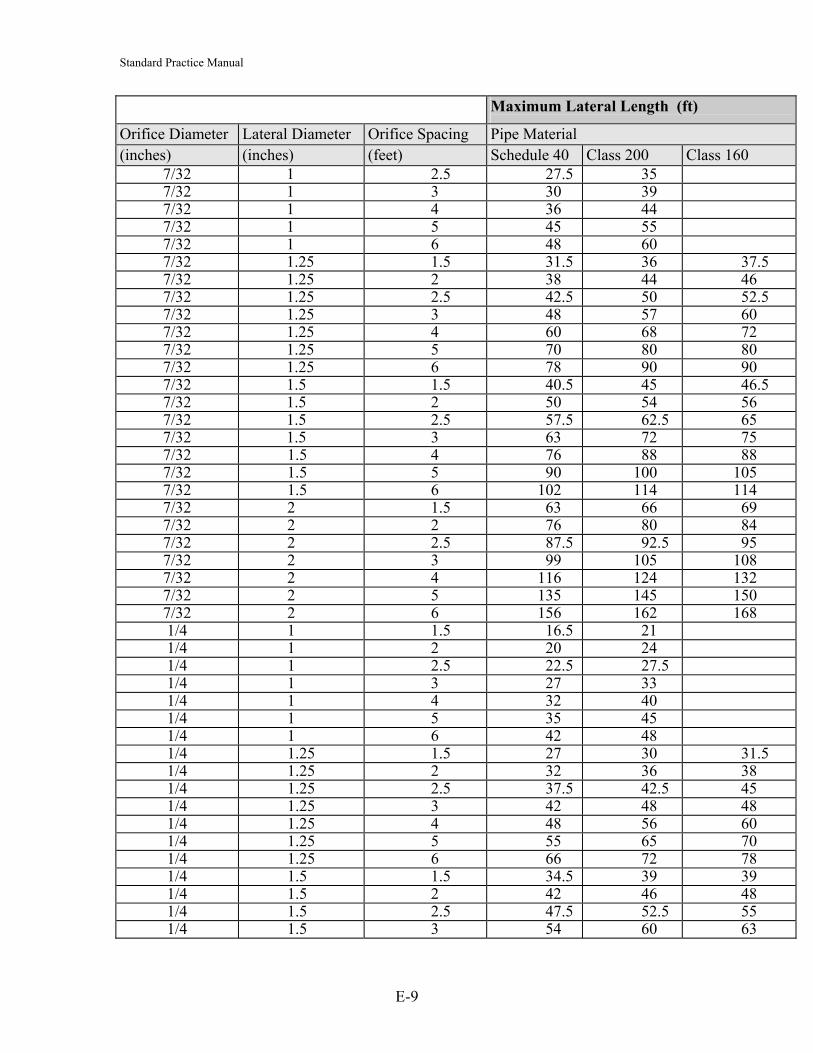
Standard Practice Manual
Maximum Lateral Length (ft)
Orifice Diameter Lateral Diameter Orifice Spacing Pipe Material (inches) (inches) (feet) Schedule 40 Class 200 Class 160
7/32 1 2.5 27.5 35 7/32 1 3 30 39 7/32 1 4 36 44 7/32 1 5 45 55 7/32 1 6 48 60 7/32 1.25 1.5 31.5 36 37.5 7/32 1.25 2 38 44 46 7/32 1.25 2.5 42.5 50 52.5 7/32 1.25 3 48 57 60 7/32 1.25 4 60 68 72 7/32 1.25 5 70 80 80 7/32 1.25 6 78 90 90 7/32 1.5 1.5 40.5 45 46.5 7/32 1.5 2 50 54 56 7/32 1.5 2.5 57.5 62.5 65 7/32 1.5 3 63 72 75 7/32 1.5 4 76 88 88 7/32 1.5 5 90 100 105 7/32 1.5 6 102 114 114 7/32 2 1.5 63 66 69 7/32 2 2 76 80 84 7/32 2 2.5 87.5 92.5 95 7/32 2 3 99 105 108 7/32 2 4 116 124 132 7/32 2 5 135 145 150 7/32 2 6 156 162 168 1/4 1 1.5 16.5 21 1/4 1 2 20 24 1/4 1 2.5 22.5 27.5 1/4 1 3 27 33 1/4 1 4 32 40 1/4 1 5 35 45 1/4 1 6 42 48 1/4 1.25 1.5 27 30 31.5 1/4 1.25 2 32 36 38 1/4 1.25 2.5 37.5 42.5 45 1/4 1.25 3 42 48 48 1/4 1.25 4 48 56 60 1/4 1.25 5 55 65 70 1/4 1.25 6 66 72 78 1/4 1.5 1.5 34.5 39 39 1/4 1.5 2 42 46 48 1/4 1.5 2.5 47.5 52.5 55 1/4 1.5 3 54 60 63
E-9

Standard Practice Manual
E-10
Maximum Lateral Length (ft)
Orifice Lateral Orifice Spacing Pipe Material (inches) (inches) (feet) Schedule 40 Class 200 Class 160
1/4 1.5 4 64 72 76 1/4 1.5 5 75 85 85 1/4 1.5 6 84 96 96 1/4 2 1.5 52.5 55.5 58.5 1/4 2 2 64 68 70 1/4 2 2.5 72.5 77.5 801/4 2 3 81 87 90 1/4 2 4 100 104 108 1/4 2 5 115 120 125 1/4 2 6 126 138 144
Table E-2: Orifice discharge rates in gallons per minute (gpm) Head (feet) Orifice Diameter (inches) ⅛ 5⁄32
3⁄167⁄32 ¼
2 0.59 0.80 1.04 3 0.72 0.98 1.28 4 0.83 1.13 1.47 5 0.41 0.64 0.93 1.26 1.65 6 0.45 0.71 1.02 1.38 1.80 7 0.49 0.76 1.10 1.49 1.95 8 0.52 0.81 1.17 1.60 2.08 9 0.55 0.86 1.24 1.69 2.21 10 0.58 0.91 1.31 1.78 2.33
Note: Table E-2 was generated assuming that the minimum residual head at the distal orifice is 5 feet when orifices are ⅛ and 5⁄32 inch in diameter, and 2 feet for larger orifice diameters.
Source: Washington State Department of Health, 2001

Standard Practice Manual Table E-3a: Maximum manifold length in feet for orifice diameters of 3⁄16 in. and up with minimum 2 feet of residual head
Maximum Manifold Length (ft)Lateral Discharge Manifold Diameter (inches)Rate (gpm/lateral) 1 1/4 1 1/2 2 3 4 6Central End Lateral Spacing (ft)
Manifold Manifold 2 3 4 6 8 10 2 3 4 6 8 10 2 3 4 6 8 10 2 3 4 6 8 10 2 3 4 6 8 10 2 3 4 6 8 105 10 4 6 4 6 8 10 6 6 8 12 8 10 10 12 16 18 24 20 22 27 32 42 48 60 34 45 52 72 80 90 72 93 112 144 176 200
10 20 2 3 4 2 3 4 6 8 6 6 8 12 8 10 12 15 20 24 32 30 22 27 32 42 48 60 46 57 72 90 112 12015 30 2 2 3 4 4 6 4 6 8 10 10 12 12 18 24 20 16 21 24 30 40 40 34 45 52 66 80 9020 40 2 2 3 4 6 8 8 9 12 12 16 20 12 18 20 24 32 30 28 36 44 54 64 8025 50 2 3 4 6 9 8 12 16 10 10 15 16 18 24 30 24 30 36 48 56 6030 60 2 3 4 6 6 8 6 8 10 10 12 16 18 24 20 22 27 32 42 48 6035 70 2 3 4 6 8 6 8 10 8 12 12 18 16 20 18 24 28 36 40 5040 80 2 4 6 4 6 8 10 8 9 12 12 16 20 18 21 28 36 40 4045 90 4 3 4 6 8 10 6 9 8 12 16 20 16 21 24 30 32 4050 100 4 3 4 6 8 10 6 9 8 12 16 10 14 18 24 30 32 4055 110 2 3 4 6 8 6 6 8 12 8 10 14 18 20 24 32 3060 120 2 3 4 6 6 6 8 12 8 10 12 15 20 24 32 3065 130 2 3 4 6 6 6 8 6 8 10 12 15 20 24 24 3070 140 2 3 4 4 6 8 6 8 10 12 15 16 24 24 3075 150 2 3 4 4 6 8 6 8 10 10 15 16 18 24 3080 160 2 3 4 4 6 4 6 8 10 10 12 16 18 24 3085 170 2 3 4 6 4 6 8 10 10 12 16 18 24 2090 180 2 3 4 3 4 6 8 10 10 12 12 18 24 2095 190 2 3 4 3 4 6 8 10 8 12 12 18 16 20
100 200 2 4 3 4 6 8 10 8 12 12 18 16 20Instructions: These Tables can be used to determine maximum length of a given diameter manifold or to determine required minimum diameter for a given manifold length. Known values must include:
Manifold - lateral configuration (end or central) Lateral discharge rate “Q” in gallons per minute Lateral spacing in feet
Example A: Central manifold configuration, lateral discharge “Q” = 40 gpm, lateral spacing = 6 ft., manifold diameter = 4 inch; Maximum length = 12 ft. Example B: End manifold configuration, lateral discharge “Q” = 30 gpm, lateral spacing = 6 ft., manifold length = 18 ft.; Minimum diameter = 3 inch
Source: Washington State Department of Health, 2001
E-11

Maximum Manifold Length (ft)
E-12
Table E-3b: Maximum manifold length in feet for orifice diameters of 1⁄8 in. and 5⁄32 in. with minimum 5 feet of residual head
Lateral Discharge Rate (gpm) Manifold Diameter (inches)
pm/lateral) 1 1/4 1 1/2 2 3 4 6End Lateral Spacing (ft)
fold Manifold 2 3 4 6 8 10 2 3 4 6 8 10 2 3 4 6 8 10 2 3 4 6 8 10 2 3 4 6 8 10 2 3 4 610 6 9 8 12 16 10 8 12 12 18 16 20 14 18 20 30 32 40 30 39 48 60 72 80 48 63 76 96 120 130 100 129 156 204 220 4 3 4 6 8 10 4 6 8 6 8 10 8 12 12 18 16 20 18 24 28 36 40 50 30 39 48 60 72 80 64 81 100 126 15
5 30 2 3 4 4 3 4 6 8 10 6 6 8 12 8 10 14 18 20 24 32 30 22 30 36 42 56 60 48 63 76 96 140 2 2 3 4 6 4 6 8 6 8 10 12 15 16 18 24 30 18 24 28 36 40 50 40 51 60 78 9650 2 3 4 4 6 4 6 8 10 10 12 12 18 16 20 16 21 24 30 40 40 34 45 52 66 8060 2 4 3 4 6 8 10 8 9 12 12 16 20 14 18 20 24 32 40 30 39 48 60 72
5 70 2 2 3 4 6 8 9 12 12 16 20 12 15 20 24 24 30 26 36 40 54 60 80 2 3 4 6 9 8 12 16 10 12 15 16 18 24 30 24 30 36 48 5
90 2 3 4 6 6 8 12 8 10 10 12 16 18 24 20 22 30 36 42 56100 2 3 6 6 8 6 8 10 10 12 12 18 24 20 20 27 32 42 48
5 110 2 3 4 6 8 6 8 10 8 12 12 18 16 20 20 24 28 36 4120 2 4 6 8 6 8 10 8 9 12 12 16 20 18 24 28 36 40130 2 4 6 4 6 8 10 8 9 12 12 16 20 18 21 28 36 40140 2 4 6 4 6 8 10 8 9 12 12 16 20 16 21 24 30 40150 4 3 4 6 8 10 6 9 8 12 16 20 16 21 24 30 32160 4 3 4 6 8 10 6 9 8 12 16 10 14 18 24 30 32170 4 3 4 6 8 6 9 8 12 16 10 14 18 20 30 32
0 180 2 3 4 6 8 6 6 8 12 8 10 14 18 20 24 35 190 2 3 4 6 8 6 6 8 12 8 10 14 18 20 24 30 200 2 3 4 6 6 6 8 12 8 10 12 15 20 24 3
Rate (gCentral
Mani 8 105 40 28010 2 1801 12 13020 11025 9030 803 4 704 6 7045 6050 605 8 5060 5065 5070 4075 4080 4085 409 2 309 2 3010 2 30
Source: Washington State Department of Health, 2001
Standard Practice Manual

Standard Practice Manual
Table E-4: Constant “K” values Nominal Diameter (") Schedule 40 Class 200 Class 160
1 47.8 66.5 1.25 98.3 122.9 129.4 1.5 147.5 175.5 184.8 2 284.5 315.2 332.5 2.5 454.1 520.7 551.1 3 803.9 873.3 920.5 4 1,642.9 1,692.7 1,783.9 6 4,826.6 4,677.4 4,932
Source: Washington State Department of Health, 2001
Table E-5: Equivalent length of pipe in feet of friction loss for PVC fittings Pipe Size (inches)
90o
Elbow 45o
Elbow Through Tee Run
Through Tee Branch
.5 1.5 0.8 1.0 4.0
.75 2.0 1.0 1.4 5.0 1 2.25 1.4 1.7 6.0 1.25 4.0 1.8 2.3 7.0 1.5 4.0 2.0 2.7 8.0 2 6.0 2.5 4.3 12.0 2 1/2 8.0 3.0 5.1 15.0 3 8.0 4.0 6.3 16.0 4 12.0 5.0 8.3 22.0 6 18.0 8.0 12.5 32.0 8 22.0 10.0 16.5 38.0
Source: Washington State Department of Health, 2001
Table E-6: Volume of pipes in gallons per foot (gpf) Type of Pipe
Nominal Diameter (") PR 160 PR 200 Schedule 40 0.75 0.035 0.028 1 0.058 0.058 0.045 1.25 0.098 0.092 0.078 1.5 0.126 0.121 0.106 2 0.196 0.188 0.174 2.5 0.288 0.276 0.249 3 0.428 0.409 0.384 4 0.704 0.677 0.661 5 1.076 1.034 1.039 6 1.526 1.465 1.501 8 2.586 2.485
10 4.018 3.861 12 5.652 5.432
Source: Washington State Department of Health, 2001
References Converse, J.C. (2000) Pressure Distribution Network Design. Washington State Department of Health (2001). Pressure Distribution Recommended Standards and Guidance for Performance, Application, Design, and Operation and Maintenance.
E-13

Standard Practice Manual
Appendix F: Mound Systems
1 GENERAL
The mound is an above-grade soil absorption system used for wastewater treatment and dispersal. The mound system consists of a septic tank, a dosing chamber and the mound itself. The principal features of the mound are a layer of gravel or aggregate for distribution of the wastewater, a layer of special sand imported to the site, and a layer of the native permeable unsaturated soil on the site. Figure F-1 shows a typical mound system.
The design of the system depends on wastewater characteristics, siting requirements, loading rates and sizing.
Acknowledgements: This paper is adapted from the references shown.
2 EVALUATION OF WASTEWATER CHARACTERISTICS
The first step in designing a mound system is to evaluate the wastewater characteristics. Wastewater quality and quantity are the characteristics most important to designing any soil absorption system, including mound systems. Generally the design is based on typical domestic wastewater effluent having received primary treatment in a septic tank. However, the design of a mound can be altered to suit situations where the effluent has received greater treatment, such as through aerobic treatment units or biological filters. In these cases design alterations include increasing the loading rates to the mound and decreasing vertical separation.
Stronger non-residential wastewater such as from restaurants also requires design alterations. High-strength wastewater must be treated to an equal quality as domestic septic tank effluent before being applied to the mound or else the loading rate must be reduced so that organic loading is no greater than that of domestic wastewater.
The design flow rate is as derived from Section 4 of the Standard Practice Manual (SPM).
3 SITING CRITERIA
The designer must be knowledgeable of the soil horizons and how wastewater will travel in different soil profiles. The siting, size and configuration of a mound will depend on this. More restrictive soil profiles will require longer and narrower mound configurations. Some sites have soil profiles that are inappropriate for mound systems and should not be used for such.
F-1

Standard Practice Manual
3.1 Vertical Separation
Vertical separation refers to the depth of native permeable unsaturated soil and fill above a limiting layer such as bedrock or the high water table. The depth of native soil above the limiting layer can determine the height of the fill required in the mound, as discussed in Section 5.5 of the SPM.
Bedrock is defined as material in which at least 50% by volume is rock. It can be divided into three classes: crevice, non-crevice semi-permeable or non-crevice impermeable. Treatment can continue within the non-crevice semi-permeable and crevice bedrock types depending on their characteristics. For example, if crevices are filled with soil, treatment may continue although it will be greatly reduced.
3.2 Soil Permeability
The recommended soil basal loading rates can be found in Section 5.6 of the SPM.
3.3 Filled Areas
Filled areas are those in which soil has been brought in to raise the site. Fill texture and structure can range greatly, from sand to clay and from massive to platy, respectively, resulting in variability in the permeability of the soil. Mounds can be located in filled areas, but the increase in variability requires greater inspection of the soil and knowledge of fill in order to predict the movement of wastewater.
3.4 Slopes
The slope of a site does not limit the effectiveness of treatment within a mound. Steeply sloping sites should have long and narrow mounds installed in order to decrease the likelihood of leaks. The only slope restrictions are to do with safety and construction techniques. It is recommended for these purposes that mounds not be built on sites with slopes of greater than 25%. As with any other work, safety is paramount; WCB Regulations must be complied with.
3.5 Flood Plains
Mounds, and all soil absorption systems, should not be located within a flood plain or in any surface depressions where water might pond or drain.
3.6 Horizontal Setbacks
Horizontal setbacks should be the same for mounds as for any other soil absorption system. As a minimum, setbacks should be measured from the edge of the required basal area, and greater actual separation distances might be required to accommodate to the toe of the prescribed slopes on the property.
F-2

Standard Practice Manual
3.7 Trees and Boulders
Large trees and boulders can inhibit site preparation and soil absorption and are therefore generally avoided. However, if there are no other desirable locations to site a mound, trees can be cut to ground level and stumps and boulders left in place. On sites where tree stumps or boulders occupy a significant area, the mound’s basal area should be increased to ensure its ability to accept effluent.
4 DESIGN CRITERIA
Once the designer has sufficient information regarding the wastewater characteristics and soil and site conditions, the design of the mound itself can begin. Mound design requires estimating the site’s sand media loading rate, basal loading rate and linear loading rate after which the system can be sized.
4.1 Sand Fill Loading Rate
The maximum design loading rate of the aggregate/sand interface is shown in Table F-1. The loading rate is a function of the level of treatment.
Table F-1: Sand fill loading rates as a function of level of treatment Level of Treatment Sand Fill Loading Rate (Lpd/m2) Type 1 32 Type 2 64 Type 3 128
4.1.1 Fill Type The Mound Sand fill media must be carefully selected in order to ensure sufficient treatment of the effluent and to prevent clogging. Very coarse sands will allow the effluent to pass through too quickly and will therefore not adequately treat it while medium to fine sands can result in clogging unless the loading rate is very low, which is impractical. The required fill is very similar to the fine aggregate used for concrete, meeting ASTM Standard C33-97, except that the content of fines is restricted. Table F-2 shows the sieve analysis of the Mound Sand and the C33 specification.
Table F-2: Mound sand and C33 fine aggregate sieve analysis Sieve Percent Passing
Specification Mound Sand ASTM C33-97 Fine Aggregate 9.5 mm (⅜ inch) 100 100 4.75 mm (No. 4) 95 to 100 95 to 100 2.36 mm (No. 8) 80 to 100 80 to 100 1.18 mm (No. 16) 50 to 85 50 to 85 600 um (No. 30) 25 to 60 25 to 60 300 um (No. 50) 10 to 30 10 to 30 150 um (No. 100) <4 2 to 10
F-3
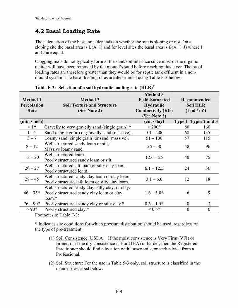
Standard Practice Manual
4.2 Basal Loading Rate
The calculation of the basal area depends on whether the site is sloping or not. On a sloping site the basal area is B(A+I) and for level sites the basal area is B(A+I+J) where I and J are equal.
Clogging mats do not typically form at the sand/soil interface since most of the organic matter will have been removed by the mound’s sand before reaching this layer. The basal loading rates are therefore greater than they would be for septic tank effluent in a non-mound system. The basal loading rates are determined using Table F-3 below.
Table F-3: Selection of a soil hydraulic loading rate (HLR)v
Method 1 Percolation
Rate
Method 2 Soil Texture and Structure
(See Note 2)
Method 3 Field-Saturated
Hydraulic Conductivity (Kfs)
(See Note 3)
Recommended Soil HLR (Lpd / m2)
(min / inch) (cm / day) Type 1 Types 2 and 3< 1* Gravelly to very gravelly sand (single grain).* > 200* 80 160 1 – 2 Sand (single grain) or gravelly sand (massive). 101 – 200 68 135 3 – 7 Loamy sand (single grain) or sand (massive). 51 – 100 57 115
8 – 12 Well structured sandy loam or silt. Massive loamy sand. 26 – 50 48 96
13 – 20 Well structured loam. Poorly structured sandy loam or silt. 12.6 – 25 40 75
20 – 27 Well structured silt loam or silty clay loam. Poorly structured loam. 6.1 – 12.5 24 36
28 – 45 Well structured sandy clay loam or clay loam. Poorly structured silt loam or silty clay loam. 3.1 – 6.0 12 18
46 – 75* Well structured sandy clay, silty clay, or clay. Poorly structured sandy clay loam or clay loam.*
1.6 – 3.0* 6 9
76 – 90* Poorly structured sandy clay or silty clay.* 0.6 – 1.5* 0 3 > 90* Poorly structured clay.* < 0.5* 0 0
Footnotes to Table F-3:
* Indicates site conditions for which pressure distribution should be used, regardless of the type of pre-treatment.
(1) Soil Consistence (USDA): If the moist consistence is Very Firm (VFI) or firmer, or if the dry consistence is Hard (HA) or harder, then the Registered Practitioner should find a location with looser soils, or seek advice from a Professional.
(2) Soil Structure: For the use in Table 5-3 only, soil structure is classified in the manner described below.
F-4

Standard Practice Manual
(3) For Method 3 only, a Professional may calculate a design soil hydraulic loading rate using equations in Appendix C.
Classification of Soil Structure for Selecting a Soil Hydraulic Loading Rate:
(1) For structured soils: (a) a structure type of granular, blocky, prismatic, or columnar is classed as Well Structured; (b) platy and wedge structures are classed as Poorly Structured.
(2) For non-structured soils: (a) single grain is classed as Well-Structured; (b) massive is classed as Poorly Structured.
Pressure Distribution: When using Table F-3, pressure distribution should be required if any one of the following conditions are met:
(a) The distribution system is a sand mound.
The pre-treatment system is a Type 2 or Type 3 system.
Any soil characteristic indicated in the table with *.
4.3 Hydraulic Linear Loading Rate
The hydraulic linear loading rate is the amount of wastewater applied per linear metre along the natural contour per day.
Once through the clogging layer and in the soil, wastewater moves in the same way any soil water moves. In a free draining soil in a humid environment, or for infiltration systems of sufficient volume, water will flow predominantly downward. Downward moving water reaching a horizon of lower permeability than the rate of precipitation, or precipitation plus added wastewater, will saturate. Some of the saturated zone water will continue downward movement but much will move horizontally down hill through more permeable shallow horizons. The steeper the slope the faster the water moves. If horizons are perfectly level then the water will build a mound beneath the infiltration surface and the groundwater surface created by the mound becomes the hill to drive the horizontal water movement. (Tyler and Kuns)
Horizontally moving effluent, if it does not reach the ground surface, will move through the layer of native permeable unsaturated soil above the impervious layer, that would have been identified in the soil investigation prior to construction of the system.
This soil depth must continue down the slope beyond the toe of the mound. If shallower horizons exist downslope, the entire soil will saturate and the system will fail. The goal is to keep all of the water below the ground surface to provide treatment by the soil and protect against human contact. The thicker the infiltration distance the more water movement possible. (Tyler and Kuns)
F-5

Standard Practice Manual The horizontal flow is also dependent on the ability of the soil to move the water horizontally. This is known as saturated horizontal hydraulic conductivity. Saturated hydraulic conductivity is related to soil pore sizes and to the field described soil characteristics utilized to determine wastewater infiltration or loading rates. The more permeable the soil, the greater the horizontal flow. (Tyler and Kuns)
The estimated horizontal flow capacity, in excess of the natural flow, is the hydraulic linear loading rate for the design of the system. Hydraulic linear loading rate is the volume of wastewater the landscape can accept per unit length of system per unit of time. Hydraulic linear loading rate is determined using the field determined slope, horizon thickness and percolation rate, soil texture and structure and hydraulic conductivity, as described in Section 4 of the Standard Practice Manual. Hydraulic linear loading rates may not be limiting to the design of some wastewater infiltration systems. Hydraulic linear loading rate is only limiting if there is a vertical flow restricting horizon below the infiltration surface. In some situations oxygen supply may be limiting.
Table F-4 provides Hydraulic Linear Loading Rates for the sites with the soil characteristics as described in Section 4 of the SPM, for different levels of treatment, different depths of native permeable unsaturated soil to the top of the limiting layer on the site (not including the depth of sand fill) and for different slopes.
Slope and depth of native permeable unsaturated soil are across the top of the table. Slope is the slope of the top of the flow-restricting horizon, which in many soil settings is also the slope of the ground surface. This value must be measured for the area proposed for wastewater infiltration. Infiltration distance may be one horizon, a portion of a horizon or portions of several horizons. The depth of native permeable unsaturated soil to the top of the limiting layer must be confirmed to be available downslope to confirm wastewater will remain below ground. (Tyler and Kuns)
5 MOUND SIZING
Once the loading rates have been determined, the designer can begin sizing the mound. The dimensions required to size the mound are shown in Figure F-1, an illustration of the cross-sectional and plan views of a mound on a sloping site.
5.1 Absorption Area Width
The first dimension to calculate is the width (A) of the absorption area. This is calculated by dividing the linear loading rate (Lpd/m) by the sand loading rate (Lpd/m2) to get the width in metres.
A = Linear Loading Rate / Sand Loading Rate The width can also be selected by the designer instead of calculated and it is recommended that it be less than 3 metres.
On sloping sites the absorption bed can be divided into multiple beds on different elevations subject to there being a spacing between beds of 90 cm, the total width being at least equal to the required width, and basal area requirements being met. Terracing the
F-6

Standard Practice Manual absorption area in this manner might reduce the about of sand fill to meet the fill slope requirements and the overall footprint of the mound on sloping sites.
5.2 Absorption Area Length
Next, the length (B) of the absorption area can be determined. This is the length of the area along the natural surface contours. It can be calculated by dividing the design flow rate (L/d) by the linear loading rate (Lpd/m) to get the length in metres.
B = Design Flow Rate ÷ Linear Loading Rate
Figure F-1: Cross section and plan views of a mound system on a sloping site.
Source: Converse and Tyler, 2000.
F-7

Standard Practice Manual
5.3 Basal Length and Width
The basal length is equal to the length of the absorption area (B), while the basal width is greater. The basal width is equal to A + I on sloping sites and A+I+J on level sites where I and J are equal. These are both calculated as the hydraulic linear loading rate (Lpd/m) divided by the basal loading rate (Lpd/sqm).
A+I (for sloping sites) or A+I+J (for level sites) = Linear Loading Rate ÷ Basal Loading Rate
5.4 Mound Fill Depth
As previously discussed, the depth (D) of the mound (distance between the distribution system and the soil surface) depends on both the required separation distance to a limiting layer and the depth from the surface to any such limiting layer. The depth is calculated as the difference between the required separation distance and the depth from the soil surface to the limiting layer.
5.5 Downslope Mound Fill Depth
The downslope mound fill depth (E) is the distance between the absorption area and the soil surface on the downslope edge. This depth of fill is what keeps the absorption area level. It depends on the original slope of the site and the width (A) and depth (D) of the absorption area. It is calculated as the slope (%) multiplied by the absorption area width (A) plus the mound fill depth (D) as calculated above.
E = D + A (Slope %)
5.6 Absorption Area Thickness
F is the thickness of the absorption area, including the aggregate material both above and below the distribution laterals as well as the diameter of the pipes. It is recommended that this value be at least 23 cm: 15 cm of aggregate below and 8 cm of aggregate above the distribution pipe and 2.5 cm for the pipe itself.
5.7 Mound Cover
Mound covers are required to allow for vegetation to grow and to prevent the surface above the absorption area from eroding. However, the soil must still be able to provide oxygen to the absorption area below. It is recommended that sandy loam, loamy sands and silt loams be used in the mound cover for this purpose. Clay loam, silty clay loam and clay soils are not recommended.
In Figure F-1, G and H respectively indicate the depth of the mound cover over the edges and the centre of the absorption area. The depth for G is recommended as 15 cm. The depth for H is recommended as 30 cm so that there is enough of a slope to encourage
F-8

Standard Practice Manual runoff; however a full 15 cm of difference in height is not required if the absorption area is narrow. These depths are lower than the traditionally recommended depth of 30 to 45 cm so that more oxygen can be transferred.
5.8 Side Slope Widths
For a sloping site, the downslope width (I) and upslope width (J) depend on the depth of the mound at the downslope and upslope edges, respectively, of the absorption area, the desired final slope and the original slope of the site. The desired final slope is usually to be 3:1 for safety reasons, such as for when mowing. Up and down-slope correction factors are given in Table F-5, based on the original slope. The slope widths are calculated as follows:
I = 3 (E+F+G) (Slope Correction Factor) J = 3 (D+F+G) (Slope Correction Factor)
On level sites both slope widths are equal and depend only on the depth of the mound at the edges of the absorption area and the desired slope. Slope widths could also be calculated by subtracting the absorption area width (A) from the basal width (A+I for sloping sites or A+I+J for level sites where I and J are equal).
5.9 End Slope Length
The end slope length (K) also depends on the same factors as the widths of the side slopes except that it considers the depth of the mound at the centre of the absorption area instead of the edges. It also depends on a suggested slope of 3:1. Typically, the slope length is 2.5 to 3.6 metres.
5.10 Overall Length and Width
The overall length is calculated as the absorption area length (B) plus two times the end slope length (K). The overall width is equal to A+I+J where I and J are different for sloping sites and equal for level sites.
6 DESIGN A PRESSURE DISTRIBUTION NETWORK
A pressure distribution network, including the distribution piping, dosing chamber and pump, must be designed using the procedure described elsewhere in the SPM.
• Use 4.7 mm (3⁄16") holes for effluent from a septic tank with effluent filter. For higher levels of treatment, 3.1 mm (⅛") holes could be used.
• Using 0.56 m2 of sand infiltrative surface per orifice • Provide easy access to flush the laterals such as turn-ups at end of laterals. • Dose volume at 5 times the lateral pipe volume and not to exceed 20% of the design • Timed dosing is preferred, which requires surge capacity in the septic tank/pump
chamber.
F-9

Standard Practice Manual
7 MOUND CONSTRUCTION
The following is from Converse, J.C. and Tyler, E.J. (2000), and represents the current thinking on mound construction:
A construction plan for any on-site system is essential. A clear understanding between the site evaluator, the designer, contractor and inspector is critical if a successful system is installed. It is important that the contractor and inspector understand the principles of operation of the mound system before construction commences otherwise the system will not function as intended. It is also important to anticipate and plan for the weather. It is best to be able to complete the mound before it rains on it. The tilled area (basal area) and the absorption area must be protected from rain by placing sand on the tilled area and aggregate on the absorption area prior to precipitation. There are several different ways to construct a mound as long as the basic principles and concepts are not violated. The following are suggested construction steps:
(1) The mound must be placed on the contour. Measure the average ground surface elevation prior to tillage along the up slope edge of the absorption area. This contour will serve as the base line for determining the elevation of the bottom of the absorption area.
(2) Grass, shrubs and trees must be cut close to the ground surface and removed from the site. In wooded areas with excess litter, it is recommended to rake the majority of it from the site. Do not pull out the stumps and do not remove the sod or the top soil or boulders.
(3) Determine where the force main from the pump chamber enters the mound. It will either be center feed or end feed. For long mounds, center feed is preferred and all end feeds can be made into center feed. For center feed the force main can enter from the up slope center (preferred), the down slope center or exit the native soil at the end and be placed horizontally on a slight slope in the sand beneath the aggregate or just up slope of the aggregate. If it must be brought in from the down slope side, especially on slowly permeable soils with high seasonal saturation where the effluent flow may be horizontal, it should be brought in perpendicular to the side of the mound with minimal disturbance to the down slope area. All vehicular traffic must be kept in a very narrow corridor. Minimal damage is done if the soil is dry. Soil should be packed around the pipe and anti-seep collars should be installed to minimize effluent and water following the pipe. Entering from the down slope center should be the last choice on sites that are slowly permeable with shallow seasonal saturation.
(4) The footprint of the mound must be tilled only when the soil moisture is within a satisfactory range. The satisfactory moisture range, to a depth of 6-7", is defined as where the soil will crumble and not form a wire when rolled between the palms. The purpose of tillage is to roughen the surface to allow better infiltration into the top soil. It also provides more contact between the sand and the soil. Excessive tillage will destroy soil structure and reduce
F-10
Standard Practice Manual
infiltration. The preferred methods in order of preference are i) using chisel teeth mounted on a backhoe which can be easily removed, ii) using a chisel plough pulled behind a tractor, and iii) using a backhoe bucket with short teeth which requires flipping the soil. Normally it takes much longer to use the backhoe bucket than a chisel teeth mounted on the backhoe with the added cost quickly recovered. Mouldboard ploughs have been used successfully but are the least preferred. Rototillers are prohibited on structured soils but may be used on unstructured soils such as sand to break up the vegetation. However, they are not recommended. All tilling must be done following the contour.
If a platy structure is present in the upper horizons, the tillage depth should be deep enough to try to break it up without bringing an excessive amount of subsoil to the surface. Deep tilling for the sake of deep tilling is not recommended. Till around the stumps without exposing an excessive amount of roots. Chisel teeth, mounded on a backhoe, is the preferred and an easier method for tilling around stumps. Stumps are not to be removed but some small ones may be inadvertently pulled out during tilling. If so, remove them from the site. If there are an excessive number of stumps and large boulders, the basal area should be enlarged or another site selected but that is the rare occasion.
(5) Once the site has been tilled, a layer of sand must be placed before it rains. Driving on the exposed tilled soil is prohibited so as not to compact it or rut it up. Sand should be placed with a backhoe (preferred) or placed with a blade and track type tractor. A wheeled tractor will rut up the surface. All work is to be done from the up slope side so as not to compact the down slope area especially if the effluent flow is horizontally away from the mound.
(6) Place the proper depth of sand, then form the absorption area with the bottom area raked level. The sand should be reasonably compacted in the trench area to minimize settling. A good backhoe operator can form the trench with minimal hand work.
(7) Place a clean sound aggregate to the desired depth. Limestone is not recommended. If chambers are used, proper procedures must be performed to keep the chambers from settling into the sand. Procedures are available from the manufacturers that include compacting the sand to a certain specification and placing a coarse netting on the compacted surface prior to chamber placement.
(8) Place the pressure distribution network with holes located downward and cover it with 2.5 cm (1 in.) of aggregate. Connect the force main to the distribution network. If chambers are used, the pressure distribution laterals must be suspended from the chambers with holes upward. Provisions must be made to allow the laterals to drain after dosing. This is accomplished by having several holes located downward or sloping the pipe in the chamber toward the force main. The laterals and force main must drain after each dose.
F-11

Standard Practice Manual
F-12
(9) Cover the aggregate with a geotextile synthetic fabric.
(10) Place suitable soil cover on the mound. There should be 15 cm (6") on the sides and shoulder (G) and 30 cm (12") on the top center (H) after settling. The soil cover should support vegetation. If not, provisions must be made to control erosion.
(11) Final grade the mound and area so surface water moves away from and does not accumulate on the up slope side of the mound. Use lightweight equipment.
(12) Seed and mulch the entire exposed area to avoid erosion. Advise the homeowner on proper landscaping. The top of the mound becomes dry during the summer and the down slope toe may be wet during the wet seasons. Avoid deep rooted vegetation on the top of the mound to minimize root penetration into the distribution network
(13) Inform homeowner about the type of system, maintenance requirements and do’s and don’ts associated with on-site soil based systems.

F-13
Table F-4: Linear hydraulic loading rates for mound systems
Soil Characteristics Linear Hydraulic Loading Rate (Litres of Design Flow per
Day per Metre of Mound Length) Slope
Method 1 Method 2 Method 3 0-4 % 5-9 % >10 %
Percolation Rate Soil texture and structure
Field-Saturated Hydraulic
Conductivity (Kfs)
Depth of Native Permeable Soil (mm)
Depth of Native Permeable Soil (mm)
Depth of Native Permeable Soil (mm)
Min / inch cm / day 200-305 305-610 >610 200-305 305-610 >610 200-305 305-610 >610< 1* Gravelly to very gravelly sand (single grain)** > 200* no no no no no no no no no 1 – 2 Sand (single grain) or gravelly sand (massive) 100 – 200 37 43 50 45 51 57 62 74 87 3 – 7 Loamy sand (single grain) or sand (massive) 50 – 100 37 43 50 45 51 57 62 74 87
8 – 12 Well structured sandy loam or silt. 25 – 50 37 43 50 45 51 57 50 62 74 Massive loamy sand.
13 – 20 Well structured loam. 12.5 – 25 37 43 50 41 47 53 45 51 57 Poorly structured sandy loam or silt. 25 31 37 27 34 40 30 36 42
20 – 27 Well structured silt loam or silty clay loam. 6.0 – 12.5 25 31 37 27 34 40 30 36 42 Poorly structured loam.
28 – 45 Well structured sandy clay loam or clay loam. 3.0 – 6.0 25 31 37 27 34 40 30 36 42 Poorly structured silt loam or silty clay loam.
46 – 75* Well structured sandy clay, silty clay, or clay. 1.5 – 3.0* no no no no no no no no no Poorly structured sandy clay loam or clay loam.* no no no no no no no no no
76 – 90* Poorly structured sandy clay or silty clay.* 0.5 – 1.5* no no no no no no no no no > 90* Poorly structured clay.* < 0.5* no no no no no no no no no
Footnotes to Table F-4 * For these soils, with a very high or very low permeability, a design linear loading rate must be calculated by a qualified Professional. Soil Consistence (USDA): If the moist consistence is Very Firm (VFI) or firmer, or if the dry consistence is Hard (HA) or harder, then the Registered Practitioner should find a location with looser soils, or seek advice from a Professional. Soil Structure: For the use in Table F-4, soil structure is classified in the manner described below. Classification of Soil Structure for Selecting a Linear Loading Rate: For structured soils: (a) a structure type of granular, blocky, prismatic, or columnar is classed as Well Structured; (b) platy and wedge structures are classed as Poorly Structured. For non-structured soils: (a) single grain is classed as Well-Structured; (b) massive is classed as Poorly Structured. Ref.: Adapted from Tyler, E. J. and Kuns, L. K. (circa 2000)
Standard Practice Manual
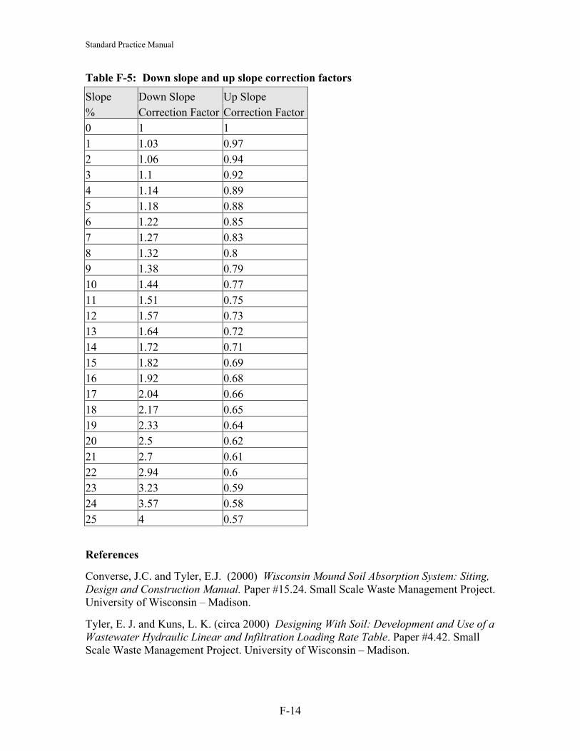
Standard Practice Manual
Table F-5: Down slope and up slope correction factors
Slope Down Slope Up Slope % Correction Factor Correction Factor 0 1 1 1 1.03 0.97 2 1.06 0.94 3 1.1 0.92 4 1.14 0.89 5 1.18 0.88 6 1.22 0.85 7 1.27 0.83 8 1.32 0.8 9 1.38 0.79 10 1.44 0.77 11 1.51 0.75 12 1.57 0.73 13 1.64 0.72 14 1.72 0.71 15 1.82 0.69 16 1.92 0.68 17 2.04 0.66 18 2.17 0.65 19 2.33 0.64 20 2.5 0.62 21 2.7 0.61 22 2.94 0.6 23 3.23 0.59 24 3.57 0.58 25 4 0.57
References
Converse, J.C. and Tyler, E.J. (2000) Wisconsin Mound Soil Absorption System: Siting, Design and Construction Manual. Paper #15.24. Small Scale Waste Management Project. University of Wisconsin – Madison.
Tyler, E. J. and Kuns, L. K. (circa 2000) Designing With Soil: Development and Use of a Wastewater Hydraulic Linear and Infiltration Loading Rate Table. Paper #4.42. Small Scale Waste Management Project. University of Wisconsin – Madison.
F-14

Standard Practice Manual
Appendix G: Flow Trials
THE FLOW TRIAL
Discussion
The flow trial is not a be-all-and-end-all test, nor is it accurate under all conditions. The results of a flow trial should always be interpreted within the context of the entire inspection. For example, if there is an obvious cave-in over the soil absorption system, the system clearly needs a major repair and a flow trial will not provide any useful information.
The test will not find every failure condition nor provide any guarantee that the existing sewage disposal system will continue to perform.
A flow trial should NOT be performed in the following situations:
(1) Evidence of structural damage to the system such as:
• broken tee or baffle • cracked tank
In this case, refer the owner to a repair Professional.
(2) The system is showing obvious signs of failure, as the flow-trial procedures may actually aggravate the problem.
(3) The system is such that flow into it is limited in volume and time, such as a system with a dosing device or a recirculating sand filter. Such a system can be damaged by excessive flooding.
Some situations may not provide reliable results for a flow trial. Examples include:
(1) The home was unoccupied for a significant period of time over the past 12 months. In this situation, a failing soil absorption system may have been temporarily renovated during the extended lack of use and will accept the full flow-trial volume. However, when the system starts receiving flows typical of an occupied home, the system may once again show signs of failure.
(2) The system has had a recent hydrogen peroxide treatment (usually evidenced by chemical scouring or a bleached-out appearance on concrete components). In this situation, the system may have been restored temporarily and will accept the full flow-trial volume. Inspectors should be mindful that use of hydrogen peroxide generally indicates an attempt to fix a major system failure, which is likely to recur.
A flow trial is typically performed using in-home water fixtures to provide the necessary volume of water. It may also be performed at the inlet of the septic tank with a garden
G-1

Standard Practice Manual house inserted into the inspection port. Be sure the hose is not immersed in the wastewater in the tank.
In some situations however, it is recommended to perform the flow trial at the septic tank outlet. These include:
(1) Over-accumulation of solids:
• depth of combined solids is greater than 85 cm (34"); • depth of scum is greater than 27.5 cm (11"); or • depth of sludge is greater than 65 cm (26").
In this situation, a flow trial performed at the inlet could result in solids carry over to, and clogging of, the soil absorption system.
(2) The inspector has not measured the depth of solids and the system has not been pumped in over 3 years. An adequately sized, conventional system, which has been pumped in the last 3 years, is unlikely to have an over-accumulation of solids; however, inspectors may wish to measure solids for added certainty.
Before performing the flow trial, the system should be inspected. The volume of water required for the flow trial should also be calculated as described in the following section.
Calculating the flow trial volume
Normal wastewater flows vary over the course of a day, peaking during the morning and evening hours when people are most likely to use the kitchen, bathroom and laundry facilities. The greatest flow that may enter a system during an hour of time is called the peak one-hour flow. As it is typically the most stressful condition experienced by a system, the peak one-hour flow is also the condition that the flow trial is designed to approximate (i.e., peak one-hour flow = flow trial volume).
The peak one-hour flow can be estimated as 8 times the average hourly flow or one third the daily flow. Systems in British Columbia are designed based on the number of bedrooms. Therefore, flow trial volumes can be calculated as one third the design flow. Table G-1 indicates flow trial volumes for homes relative to number of bedrooms and design-flow volumes.
Table G-1: Maximum flow trial volumes relative to number of bedrooms and design flow
Design Flow Flow Trial Volume No. of Bedrooms Single Family Dwelling
L/day Imp. Gal./day L Imp. Gal.
1 – 2 1136 250 375 83 3 1363 300 450 99 4 1704 375 562 124 5 2045 450 675 149 6 2500 550 825 182
G-2

Standard Practice Manual
Flow trial procedures
The following are procedures for a flow trial. Inspectors should keep in mind that a flow trial requires a large volume of water, which creates a good condition for dye tracing. If both a dye tracing and flow trial are to be done, an inspector should perform them together to avoid waste (to determine if dye tracing is necessary refer to Section 4.9, “Dye Tracing for Confirming Treatment Bypasses” of the Homeowner’s Guide).
(1) Calculate flow trial volume required based on system design (see previous section).
(2) Ask occupants to refrain from using any plumbing fixtures (e.g., sinks, toilets, washing machines, dish washers, etc.) during the flow trial.
(3) Consider the condition of the septic tank (refer to Section 4.1.1, “Examining the external condition of septic tanks” of the Homeowner’s Guide and to the first section, “Limitations of the flow trial”). If the system is not in good working order, do not proceed with the flow trial. If the inspector opts not to do the flow trial, then the tank should be pumped and the inspector should refer the system owner to a repair Professional.
In general, if a system has been pumped in the last three years, then it can be assumed that there will be no solids carryover during a flow trial. If no pumpout record is available, the inspector should measure the depth of both the scum and sludge layers.
(4) If the system appears to be in working order, the flow trial volume may be added by opening water taps in the house or with a garden hose inserted in the inlet or the outlet inspection port of the septic tank. Be sure the hose is not immersed in the wastewater in the tank. The flow trial volume (refer to the preceding section, “Calculating the flow trial volume”) may be added at a rate of between 18 - 36 L (4 - 8 imp.gal.) per minute.
If the house has a water metre, then the metre may be used to measure flow (refer to Section 6.1, "Estimating Water Use" of the Homeowner’s Guide). (Be sure to note the volume unit of flow on the metre.) If a household water metre is not present, an in-line flow metre may be used on a garden hose to measure flow rate. If no metreing device is available, flow rate from a garden hose may be estimated by opening the tap fully and timing the fill up of a 20 L (4.5 imp.gal.) bucket (refer to equation 6.2 “Flow Rate” in Section 6.2.2 of the Homeowner’s Guide, for more details).
If dye tracing is being performed on the system, dye should be added to the outlet of the septic tank during this step.
(5) If water begins to back up in the septic tank (i.e., rises more than 5 cm (2 in) above the outlet bottom), stop the flow of water. This is an indication of system failure. Inspectors should note that when first adding flow to the soil
G-3

Standard Practice Manual
absorption system, a small rise in water level (2.5 cm (1 in)) will occur in the septic tank. This is not a backup.
(6) Inspect the soil absorption system, all property areas, and adjacent ditches for evidence of failure (i.e., surfacing of water) and appearance of dye if used.
(7) The system would appear to be functioning properly if it accepts the full flow trial volume without failure. If the system did not accept the full flow-trial volume, refer the owner to a repair Professional. Record the results on an inspection report form.
Factors to consider when interpreting flow trial results include:
(a) evidence of a heavy object placed over the soil absorption system.
(b) one component or more exposed as a result of soil erosion.
G-4

Standard Practice Manual
Appendix H: Testing
1 HYDROSTATIC TESTING
Water-pressure testing determines a tank’s watertightness by maintaining a certain water level for one hour after a 24-hour absorption period.
Be careful when performing hydrostatic tests on plastic and fiberglass tanks as they gather much of their strength from the soil support. For all mid-seam tanks, keep the backfill near the mid-seam, but leave the seam itself exposed to monitor the test.
The following is a suggested water testing procedure for tanks. Note that this test does not evaluate the tank’s ability to withstand external pressures: that issue must be assured through adequate engineering design.
(1) Plug the inlet and outlet pipes with a watertight plug, pipe and cap or other seal. Seal the pipes away from the tank to test any pipe connections that may be of concern.
(2) If testing a mid-seam tank, ensure that the seam is exposed for the water test.
(3) Fill the tank to the top.
(4) If the tank has a riser, add water into the riser to a maximum of 5.0 cm above the tank/riser seam. Care must be taken not to overfill as the top section of a two-piece tank may become buoyant.
(5) Measure and record the level of the water.
(6) Let the tank sit for 24 hours. Any obvious leakage during this time should be evaluated and remedied by the application of a suitable sealing compound.
(7) If the test reveals leaks that cannot be repaired, the tank is considered unacceptable.
(8) Refill concrete tanks to original level after 24 hours as they will absorb some water.
(9) Check again after 24 hours. If less than 4 litres is lost in a concrete tank, the leak test is considered acceptable.
Tables H-2 and H-3 provide information for calculating volumes in square and round risers.
H-5

Standard Practice Manual
Table H-2: Depth change equivalent to four litres in round risers of various interior diameters. Riser Diameter (cm) Depth (cm) Equal to Four Litres 46 2.4 61 1.4 76 0.9 91 0.6
Table H-3: Depth change equivalent to four litres in square risers of given interior dimensions. Riser Dimensions (cm) Depth (cm) Equal to Four Litres18 x 18 1.9 24 x 24 1.1 36 x 36 0.5
When performing hydrostatic testing in cold climates, there are a few important points to consider. First, water is its densest at about 4 degrees C (just above freezing), so water put into a tank at 10-20 degrees C (typical of groundwater) and left in the tank overnight at freezing temperatures will drop the level in the tank a substantial amount (about 2% or 11 litres in a 5,600 litre tank). A 'loss' of 11 litres in the risers will look like a leak. Additionally, water used in the test will freeze and expand by approximately 9%. If the site is not occupied quickly the tank may crack as a result of the test itself.
2 VACUUM TESTING
Vacuum testing verifies that a tank is watertight if it holds 90 percent of a two-inch vacuum of mercury for two minutes.
Vacuum testing of tanks requires less time than hydrostatic testing and can be performed without having water available on the site. Testing should be done on the tank in its ready-to-use state (i.e., pipes in the inlet and outlet, risers with lids, etc.) In this test all pipe penetrations, manholes and risers are sealed airtight and a special insert is sealed on one of the tank manholes. Using a pump, air is evacuated through this insert to a standard vacuum level and the reading on a vacuum gage is recorded. Be careful not to exceed the recommended vacuum level. It is possible to damage or implode a tank.
The 2003 National Precast Concrete Association (US) standard states: “The recommended [vacuum test] procedure is to introduce a vacuum of 4 inches of mercury. Hold this pressure for 5 minutes. During this initial 5 minutes, there is an allowable pressure equalization loss of up to a half-inch of mercury. If the pressure drops, it must be brought back to 4 inches and held for a further five minutes with no pressure drop.”
If a tank will not hold the vacuum, leaks must be located and repaired. The test can then be repeated. If the tank cannot be repaired and rendered watertight, it should be replaced.
H-6

Standard Practice Manual Note that vacuum testing of concrete tanks draws seams together for a positive mastic seal, assuming there are no other problems. With any tank, collapse, deflection, deformation, or cracking indicate a poor quality tank. It is important to test the entire system: tank, pipe sleeves, risers, inspection ports and lids.
3 TESTING EXISTING TANKS
It is more difficult to check watertightness in an existing septic tank. Adequate testing requires a period of several hours to a day or more without inflow to the tank and sealing off inlet and outlet pipes. Seal the line at the distribution box (or other appropriate place in the case of secondary treatment units) and at the cleanout between the building and the tank. Apply vacuum or water as desired. If there are no leaks, the entire system passes in one step. If there are leaks, successive tests will locate the source or sources. Although actual testing of existing tanks may be impractical, much can be discerned by a thorough inspection of a tank both before and after it has been pumped out. Most tanks built using older methods of construction (such as built-in-place block or brick tanks) would typically not be watertight or structurally sound and probably cannot reasonably be repaired. In some cases it may be possible to do more to check existing tanks. If the soil around the tank is saturated, the tank contents can be pumped down and observations made over the next few hours to detect leakage into the tank around pipe penetrations, seams or through breaks in the tank. Caution should be exercised, however, as high groundwater may cause empty tanks to become buoyant and float out of the ground. Alternately, excessive soil pressure may collapse a tank. In some cases, it may be necessary to excavate completely around the tank to make a visual inspection for leaks. If there is any doubt about the integrity of the existing tank, it should be replaced.
H-7

Standard Practice Manual
Appendix I: Endnotes
i References: Cogger, Craig G., 1989. Seasonal high water tables, vertical separation, and system performance. In Proceedings: 6th Northwest On-Site Wastewater Treatment Short Course. September 18 - 19, 1989. Epp, P.F., 1984. Soil Constraints for Septic Tank Effluent Absorption. MOE Manual 5. United States Department of Agriculture, Natural Resources Conservation Service, 2001. National Soil Survey Handbook. Title 430-VI. ii Editorial Note Design manuals and research papers recommend various methods to estimate or select a design soil hydraulic loading rate (HLR) for an onsite sewerage system. With any method used, the intent should be to try to estimate the long-term acceptance rate (LTAR) of the native soil, considering the tendency for soil clogging and biomat formation to gradually reduce the effective permeability, or hydraulic conductivity, of the soil at or near the infiltration surface. The three main methods that are well-documented in manuals and research papers are:
• percolation tests, with empirical tables to calculate either the drainfield length or the HLR;
• soil texture, or texture and structure, used to select a soil HLR from an empirical table;
• tests of the soil’s hydraulic conductivity (K), with a formula or table to calculate the soil HLR from K.
Registered Planners and Professionals should use at least two of these three methods when selecting a design HLR. iii Reference: Loudon, T.L., T.R. Bounds, J.C. Converse, T. Konsler and C. Rock. 2005. Septic Tanks Text in (D.L. Lindbo and N.E. Deal eds.) Model Decentralized Wastewater Practitioner Curriculum. National Decentralized Water Resources Capacity Development Project. North Carolina State University, Raleigh, NC. iv Editorial Note Filling the tank will prevent caving in, collapse and floatation. Organic materials are not to be used for this purpose as they can decay, possibly leading to caving in or collapse and can produce toxic and possibly explosive gases. v Temporary Editorial Comment on Draft
Discussion of Wastewater Loading of Sand Mounds
I-8

Standard Practice Manual For the planning of a sand mound, there are two separate hydraulic loading rates that must be calculated. The first is the hydraulic loading rate for the treatment system effluent infiltrating into the C-33 sand at the base of the infiltration trenches or bed. The second is the filtered water that seeps out of the C-33 sand mound into the underlying native soil. Each of these design aspects must be considered separately.
The filtered water that seeps from the sand mound into the native soil can be considered of higher quality, or more treated, than the effluent that entered the sand mound.
If the vertical thickness of C-33 sand, from the infiltration surface to the native soil surface, is more than 45 cm (18 inches), then a sand mound will normally reduce BOD by 80% to 90%. That is, when Type 1 effluent (BOD ~ 130 mg/L) is discharged to the sand mound, the filtered effluent reaching the native soil can be considered to be Type 2 effluent (BOD < 26 mg/L). If Type 2 effluent (BOD < 45 mg/L) is discharged to the sand mound, Type 3 effluent (BOD < 9 mg/L) can be expected to seep into the native soil.
If the vertical thickness of the sand mound is more than 75 cm (30 inches), manuals and reports show that a properly operating sand mound can be expected to remove 90% to 95% of the effluent BOD. That is, Type 1 effluent discharged to the sand mound produces nearly Type 3 effluent (< 13 mg/L) at the base of the sand mound (US EPA, 2002; Crites and Tchobanoglous, 1998; Washington State, 1999).
When designing a sand mound, the basal area of the mound must be based on the expected effluent quality at the base of the mound, and the long-term acceptance rate (LTAR) of the native soil present at the base of the mound. Table F-3 may then be used for selecting a soil HLR for sizing of the base of the sand mound.
I-9