sf6 padmount catalog - g&w elec · c37.60, and iec 265 standards. ... transformer and moto r...
TRANSCRIPT

Since 1905, G&W has provided custom power solutions to utilities and electric power users aroundthe world. G&W has a wide selection of reliable, quality switching and fault interrupting products to meetthe most stringent customer requirements. Whetherthe application involves load switching, line sectionalizing, fault interruption or distribution automation, G&W can provide a solution for distributionsystem switching and pro tec tion. When spec i fy ingswitchgear, consider these features:
MAXIMUM OP ER A TOR SAFETYSF6 gas is a nontoxic, nonflammable switching di elec tric. Dead-front switch construction elim i natesany exposed live parts. Spring-assisted mech a nismsassure quick-make, quick-break operation. Viewingwindows permit visual verification of open or closedcontacts. Tamper-resistant enclosures utilize penta-head bolts and padlocking provisions. Motor ac tu a tors are avail able per mit ting remote operation.The result is max i mum operator safety.
MINIMAL MAINTENANCEG&W SF6 switches are corrosion-resistant, totallysealed and factory filled. No more field ad just ments ofcritical contact areas or concerns with environmentalcon tam i na tion or intrusions. A periodic check of thepres sure gauge is all that is re quired. Galvaneal typeenclosures assure maximum corrosion resistance.
G E N E R A L F E A T U R E S
APPLICATION VERSATILITYMulti-way Configurations — Switches are available foreither two-position or three-position (in cor po rat ing anintegral ground, tie or test position) switching. Single ormultiple sources can feed multiple loads. Bus tie configurations are available permitting multiple sourcesto feed different loads within the same switch.
Mounting Flexibility — Horizontal and vertical con fig u ra tions are available with operating apparatusac ces si ble from the front, top or side compartments.Enclosures are removable for easy cable installation orfield replacement.
Bushing Variety — Many bushing styles are availableincluding an ex clu sive disconnectable style permittingfield changeout. Cable entry can be bottom, front, backor side.
Visible Break — Load break switches can in cor po ratea visible break of all three phases.
Overcurrent Protection — Fusing or elec tron i cal lycon trolled, resettable vacuum in ter rupt ers are avail able.
Smart Grid / Lazer Solutions — Complete SCADA dis tri bu tion automation and Smart Grid solutions areavail able including automatic transfer. G&W’s Lazer distribution automation systems provide pre-engineered,time-proven solutions for automatic power restoration.

Page 4
L O A D A N D F A U L T I N T E R R U P T I N G S W I T C H E S
PUFFER VACUUMINTERRUPTERSG&W load and fault interrupting combination switches combine thetotal cost and operating benefits offuseless, elec tron i cal ly controlled,resettable overcurrent protection withthe safety and main te nance benefitsof a totally sealed, dead-front, SF6insulated device. The switch es aredesigned for automatic single or threephase fault in ter rup tion with manualload break ca pa bil i ties for systems through 35kV, 630A con tin u ous.Ratings to 900A continuous are available on certain models. Singleside access designs are available for confined space ap pli ca tions.
FEATURES
Operator Safety — G&W combination switches are totallysealed, dead-front and in su lat ed withnon flam ma ble, nontoxic SF6 gas.Operators are spring assisted for positive quick-make, quick-breakoperation. A trip-free mechanism per-mits in ter rup tion independent of theoperating handle if closing into a fault.View ing win dows permit visible indi-cation of interrupter contact position.
Minimal Maintenance — No moreroutine inspections or dielectric test-ing as with oil gear. No more contactcon tam i na tion, rodent prob lems orinsulator main te nance as with airgear. A periodic check of the gaspressure gauge is all that is required.
Three Phase Tripping — No moresingle phasing problems. Si multa -neous three phase tripping is available through the electronics andwith three phase operating han dlesfor manual operation and reset.
Protection Curve Compatibility —G&W solid state electronic controlspermit extremely ac cu rate, consistentprotection curve characteristics compared to con ven tion al fuses. Theex clu sive controls can emulate the
most common time current curves(TCC) for power fuses, relays andfuse links (oil fuse cutouts). Op tion al controls can provideground trip, inrush restraint andadjustable time delay capability.
Fully Tested — Switch es are de signed and test ed per ap pli ca blesec tions of IEEE C37.72, C37.74C37.60, and IEC 265 stan dards.
APPLICATIONS
G&W combination switches providea direct re place ment for powerfused air and vac u um-in-oilswitchgear. Some ideal applications include:
Transformer and MotorProtection — The three phase tripfeature and high continuous currentmake PVIs ideal for protectingthree phase motors and trans form -ers through 600A continuous.
Loop and Tap Switching —Standard 630A and optional 900Aloop switching is ac com plishedusing the latest puffer tech nol o gy.Tap switching through 630A and upto 25kA symmetric fault protectionis accomplished using resettable,electronically controlled vacuuminterrupters. The vacuum in ter rupt ers also function as loadbreak switches.
PNI single side access switch.
Automatic Transfer — For criticalload applications, switches can be sup plied with an automatic transfercontrol package to provide au to mat ictransfer from one source to anotherto minimize downtime.
Smart Grid / Lazer Solutions—Switches can be sup plied with motoractuators on both the line and loadside providing remote control ca pa bil i ty.Various control pack ag es includingportable controls are available.
For Smart Grid applications, G&Wworks with the top control manufac-turers of the industry, includingSchweitzer and GE, to match theright control for the job. For automatic power restoration, G&W’sLazer solution provides a pre-engineered, field proven systemwhich can be pre-assembled and factory tested prior to shipment.
Metalclad SwitchgearReplacement — Front accessdesigns can provide up to a 900Arated main bus with up to six 25kAsymmetric protected load ways for acompact, economical alternative tometalclad and metal enclosed line-ups. All switches can be equippedwith SEL relays, providing flexibility,as well as complete remote monitor-ing and control capabilities.

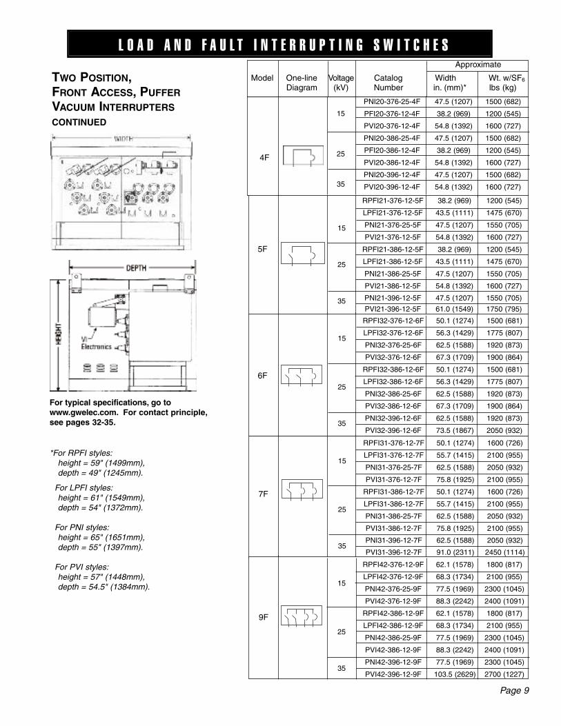
TWO POSITION, FRONT AC CESS, PUFF ERVAC U UM INTERRUPTERSCONTINUED
LINEAR PUFFER (PNI)Provides load break switch visiblebreak with 25kA symmetrical threephase fault interrupting.
Load break switch (LP) ratingsMaximum design voltage, kV ................15.5 ......27..........38Volt age class, kV ................15..........25..........35Impulse lev el (BIL), kV ................110 ......125 ......150One minute withstand, AC kV ..........35..........60..........70One minute withstand, Production test rating AC kV ..........34..........40..........5015 minute withstand, DC kV ..........53..........78........103Con tin u ous and load break cur rent, Amps* ..........630 ......630 ......630Momentary cur rent, kA asym ......40..........40..........40Fault-close cur rent, (3 times) kA asym ......40..........40..........40One second cur rent, kA sym ........25..........25..........25Open gap withstand, kV ................200 ......200 ......20010 operation over load in ter rupt ing capability, Amps ..........3000....3000....3000Operations load interrupting at 600A ........1200....1200....1200Mechanical endurance, operations....2000....2000....2000*900A continuous available
Fault interrupter (NI) ratingsMaximum design voltage, kV ................15.5......27 ........38Volt age class, kV ................15 ........25 ........35Impulse level (BIL), kV ................110......125 ....150One minute withstand, AC kV ..........50 ........60 ........70One minute withstand, Production test rating AC kV ..........34 ........40 ........5015 minute withstand, DC kV ..........53 ........78 ......103
Continuous and load break current, Amps............630......630 ....630Symmetrical in ter rupt ing rating, kA ................25 ........25 ..12.5****25kA available
IEEE C37.60Fault Interrupting DutyTotal number of fault interruptions: 116
Front access PNI with load break rotary operatorand interrupter single operating handle.
Interrupter with dual op er at ing handle.
L O A D A N D F A U L T I N T E R R U P T I N G S W I T C H E S
Model PNI-9FShown with diagonal bushingconfiguration.
Load break switch visible break.
Hookstick operable load break handle.
Optional load break switch rotary operator.
Percent ofMaximumInterruptingRating
Approx.InterruptingCurrent, Amps
No. of FaultInterruptions
15-20% 5,000 44
45-55% 12,500 56
90-100% 25,000 16
Page 7WIDTHWIDTH
HEI
GH
T
Page 9
L O A D A N D F A U L T I N T E R R U P T I N G S W I T C H E S
*For RPFI styles: height = 59" (1499mm), depth = 49" (1245mm). For LPFI styles: height = 61" (1549mm), depth = 54" (1372mm). For PNI styles: height = 65" (1651mm), depth = 55" (1397mm).
For PVI styles: height = 57" (1448mm), depth = 54.5" (1384mm).
TWO POSITION, FRONT AC CESS, PUFF ERVAC U UM INTERRUPTERSCONTINUED
For typical specifications, go towww.gwelec.com. For contact principle,see pages 32-35.
RPFI21-376-12-5F 38.2 (969) 1200 (545)
LPFI21-376-12-5F 43.5 (1111) 1475 (670)
PNI21-376-25-5F 47.5 (1207) 1550 (705)
PVI21-376-12-5F 54.8 (1392) 1600 (727)
RPFI21-386-12-5F 38.2 (969) 1200 (545)
LPFI21-386-12-5F 43.5 (1111) 1475 (670)
PNI21-386-25-5F 47.5 (1207) 1550 (705)
PVI21-386-12-5F 54.8 (1392) 1600 (727)
PNI21-396-12-5F 47.5 (1207) 1550 (705)
PVI21-396-12-5F 61.0 (1549) 1750 (795)
5F
15
25
35
Model One-line Voltage Catalog Width Wt. w/SF6
Diagram (kV) Number in. (mm)* lbs (kg)
Approximate
RPFI32-376-12-6F 50.1 (1274) 1500 (681)
LPFI32-376-12-6F 56.3 (1429) 1775 (807)
PNI32-376-25-6F 62.5 (1588) 1920 (873)
PVI32-376-12-6F 67.3 (1709) 1900 (864)
RPFI32-386-12-6F 50.1 (1274) 1500 (681)
LPFI32-386-12-6F 56.3 (1429) 1775 (807)
PNI32-386-25-6F 62.5 (1588) 1920 (873)
PVI32-386-12-6F 67.3 (1709) 1900 (864)
PNI32-396-12-6F 62.5 (1588) 1920 (873)
PVI32-396-12-6F 73.5 (1867) 2050 (932)
6F
15
25
35
RPFI31-376-12-7F 50.1 (1274) 1600 (726)
LPFI31-376-12-7F 55.7 (1415) 2100 (955)
PNI31-376-25-7F 62.5 (1588) 2050 (932)
PVI31-376-12-7F 75.8 (1925) 2100 (955)
RPFI31-386-12-7F 50.1 (1274) 1600 (726)
LPFI31-386-12-7F 55.7 (1415) 2100 (955)
PNI31-386-25-7F 62.5 (1588) 2050 (932)
PVI31-386-12-7F 75.8 (1925) 2100 (955)
PNI31-396-12 -7F 62.5 (1588) 2050 (932)
PVI31-396-12-7F 91.0 (2311) 2450 (1114)
15
25
35
PNI20-376-25-4F 47.5 (1207) 1500 (682)
PFI20-376-12-4F 38.2 (969) 1200 (545)
PVI20-376-12-4F 54.8 (1392) 1600 (727)
PNI20-386-25-4F 47.5 (1207) 1500 (682)
PFI20-386-12-4F 38.2 (969) 1200 (545)
PVI20-386-12-4F 54.8 (1392) 1600 (727)
PNI20-396-12-4F 47.5 (1207) 1500 (682)
PVI20-396-12-4F 54.8 (1392) 1600 (727 )
4F
15
25
35
7 F
9 F
RPFI42-376-12-9F 62.1 (1578) 1800 (817)
LPFI42-376-12-9F 68.3 (1734) 2100 (955)
PNI42-376-25-9F 77.5 (1969) 2300 (1045)
PVI42-376-12-9F 88.3 (2242) 2400 (1091)
RPFI42-386-12-9F 62.1 (1578) 1800 (817)
LPFI42-386-12-9F 68.3 (1734) 2100 (955)
PNI42-386-25-9F 77.5 (1969) 2300 (1045)
PVI42-386-12-9F 88.3 (2242) 2400 (1091)
PNI42-396-12-9F 77.5 (1969) 2300 (1045)
PVI42-396-12-9F 103.5 (2629) 2700 (1227)
15
25
35

Page 10
L O A D A N D F A U L T I N T E R R U P T I N G S W I T C H E S
*For RPFI styles: height = 59" (1499mm), depth = 49" (1245mm). For LPFI styles: height = 61" (1549mm), depth = 54" (1372mm). For PNI styles: height = 65" (1651mm), depth = 55" (1397mm).
For PVI styles: height = 57" (1448mm),
depth = 54.5" (1384mm).
For typical specifications, go towww.gwelec.com. For contact principle,see pages 32-35.
TWO POSITIOn,FrOnT AC CeSS, PuFF er
VACuuM In Ter ruPT erS
COnTInueD FrOnT ACCeSS PuFFer VACuuM InTerruPTerS
15
25
35
Model One-line Voltage Catalog Width Wt. w/SF6
Diagram (kV) Number in. (mm)* lbs (kg)
Approximate
RPFI43-376-12-11F 62.1 (1578) 1800 (817)
LPFI43-376-12-11F 68.8 (1746) 2075 (943)
PNI43-376-25-11F 77.5 (1969) 2400 (1091)
PVI43-376-12-11F 79.8 (2026) 2200 (1000)
RPFI43-386-12-11F 62.1 (1578) 1800 (817)
LPFI43-386-12-11F 68.8 (1746) 2075 (943)
PNI43-386-25-11F 77.5 (1969) 2400 (1091)
PVI43-386-12-11F 79.8 (2026) 2200 (1000)
PNI43-396-12-11F 77.5 (1969) 2400 (1091)
PVI43-396-12-11F 86.0 (2184) 2450 (1114)
11F
15
25
35
RPFI41-376-12-12F 62.1 (1578) 1800 (817)
LPFI41-376-12-12F 67.8 (1721) 2150 (977)
PNI41-376-25-12F 77.5 (1969) 2400 (1091)
PVI41-376-12-12F 96.8 (2459) 2600 (1182)
RPFI41-386-12-12F 62.1 (1578) 1800 (817)
LPFI41-386-12-12F 67.8 (1721) 2150 (977)
PNI41-386-25-12F 77.5 (1969) 2400 (1091)
PVI41-386-12-12F 95.0 (2413) 2600 (1182)
PNI41-396-12-12F 77.5 (1969) 2400 (1091)
PVI41-396-12-12F 121.0 (3073) 3000 (1364)
12F
15
25
35
15
25
35
51F
RPFI51-376-12-51F 74.1 (1883) 2300 (1044)
LPFI51-376-12-51F 79.7 (2025) 2600 (1182)
PNI51-376-25-51F 92.5 (2350) 2900 (1318)
PVI51-376-12-51F 118 (2997) 3100 (1409)
RPFI51-386-12-51F 74.2 (1885) 2250 (1023)
LPFI51-386-12-51F 79.7 (2025) 2600 (1182)
PNI51-386-25-51F 92.5 (2350) 2900 (1318)
PVI51-386-12-51F 118 (2997) 3100 (1409)
PNI51-396-12 -51F 92.5 (2350) 2900 (1318)
PVI51-396-12-51F 151 (3835) 3600 (1636)
RPFI43-376-12-43F-BT 74.1 (1883) 2100 (953)
LPFI43-376-12-43F-BT 80.2 (2037) 2300 (1045)
PNI43-376-25-43F-BT 92.5 (2350) 2750 (1250)
PVI43-376-12-43F-BT 101 (2565) 2700 (1227)
RPFI43-386-12-43F-BT 74.2 (1885) 2250 (1023)
LPFI43-386-12-43F-BT 80.2 (2037) 2300 (1045)
PNI43-386-25-43F-BT 92.5 (2350) 2750 (1250)
PVI43-386-12-43F-BT 101 (2565) 2700 (1227)
PNI43-396-12 -43F-BT 92.5 (2350) 2750 (1250)
PVI43-396-12-43F-BT 116 (2946) 3000 (1364)
43F
Bus Tie

Page 11
L O A D A N D F A U L T I N T E R R U P T I N G S W I T C H E S
*For RPFI styles: height = 59" (1499mm), depth = 49" (1245mm). For LPFI styles: height = 61" (1549mm), depth = 54" (1372mm). For PNI styles: height = 65" (1651mm), depth = 55" (1397mm).
For PVI styles: height = 57" (1448mm),depth = 54.5" (1384mm).
FRONT ACCESS PUFFER VACUUM INTERRUPTERS
TWO POSITION,FRONT AC CESS, PUFF ERVACUUM IN TER RUPT ERSCONTINUED
For typical specifications, go towww.gwelec.com. For contact principle,see pages 32-35.
15
25
35
Model One-line Voltage Catalog Width Wt. w/SF6
Diagram (kV) Number in. (mm)* lbs (kg)
Approximate
RPFI52-376-12-52F 74.1 (1883) 2100 (953)
LPFI52-376-12-52F 80.3 (2038) 2525 (1148)
PNI52-376-25-52F 92.5 (2350) 2800 (1273)
PVI52-376-12-52F 109.3 (2776) 2900 (1318)
RPFI52-386-12-52F 74.1 (1883) 2100 (953)
LPFI52-386-12-52F 80.3 (2038) 2525 (1148)
PNI52-386-25-52F 92.5 (2350) 2800 (1273)
PVI52-386-12-52F 109.3 (2775) 2900 (1318)
PNI52-396-12-52F 92.5 (2350) 2800 (1273)
PVI52-396-12-52F 133.5 (3391) 3250 (1477)
52F
15
25
35
RPFI53-376-12-53F 74.1 (1883) 2100 (953)
LPFI53-376-12-53F 80.8 (2051) 2450 (1114)
PNI53-376-25-53F 92.5 (2350) 2750 (1250)
PVI53-376-12-53F 101 (2565) 2700 (1227)
RPFI53-386-12-53F 74.1 (1883) 2100 (953)
LPFI53-386-12-53F 80.8 (2051) 2450 (1114 )
PNI53-386-25-53F 92.5 (2350) 2750 (1250)
PVI53-386-12-53F 101 (2565) 2700 (1227)
PNI53-396-12-53F 92.5 (2350) 2750 (1250)
PVI53-396-12-53F 116 (2946) 3000 (1364)
53F
15
25
35
RPFI54-376-12-54F 74.1 (1883) 2000 (908)
LPFI54-376-12-54F 81.3 (2064) 2400 (1091)
PNI54-376-25-54F 92.5 (2350) 2650 (1205)
PVI54-376-12-54F 93 (2362) 2500 (1136)
RPFI54-386-12-54F 74.1 (1883) 2000 (908)
LPFI54-386-12-54F 81.3 (2064) 2400 (1091)
PNI54-386-25-54F 92.5 (2350) 2650 (1205)
PVI54-386-12-54F 93 (2362) 2500 (1136)
PNI54-396-12-54F 92.5 (2350) 2650 (1205)
PVI54-396-12-54F 98.5 (2502) 2700 (1227)
54F
15
25
35
62F
RPFI62-376-12-62F 86.1 (2188) 2400 (1089)
LPFI62-376-12-62F 92.3 (2343) 2800 (1273)
PNI62-376-25-62F 107.5 (2731) 3300 (1500)
PVI62-376-12-62F 130.3 (3308) 3400 (1545)
RPFI62-386-12-62F 86.1 (2188) 2400 (1089)
LPFI62-386-12-62F 92.3 (2343) 2800 (1273)
PNI62-386-25-62F 107.5 (2731) 3300 (1500)
PVI62-386-12-62F 130.3 (3310) 3400 (1545)
PNI62-396-12-62F 107.5 (2731) 3300 (1500)

Page 12
*For RPFI styles: height = 59" (1499mm), depth = 49" (1245mm). For LPFI styles: height = 61" (1549mm), depth = 54" (1372mm). For PNI styles: height = 65" (1651mm), depth = 55" (1397mm).
For PVI styles: height = 57" (1448mm),depth = 54.5" (1384mm).
For typical specifications, go towww.gwelec.com. For contact principle,see pages 32-35.
TWO POSITION,FRONT AC CESS, PUFF ERVACUUM IN TER RUPT ERSCONTINUED FRONT ACCESS PUFFER VACUUM INTERRUPTERS
15
25
35
Model One-line Voltage Catalog Width Wt. w/SF6
Diagram (kV) Number in. (mm)* lbs (kg)
Approximate
RPFI63-376-12-63F 86.1 (2188) 2400 (1089)
LPFI63-376-12-63F 92.8 (2356) 2750 (1250)
PNI63-376-25-63F 107.5 (2731) 3200 (1455)
PVI63-376-12-63F 122 (3099) 3200 (1455)
RPFI63-386-12-63F 86.1 (2188) 2400 (1089)
LPFI63-386-12-63F 92.8 (2356) 2750 (1250)
PNI63-386-25-63F 107.5 (2731) 3200 (1455)
PVI63-386-12-63F 122 (3099) 3200 (1455)
PNI63-396-12-63F 107.5 (2731) 3200 (1455)
PVI63-396-12-63F 146 (3708) 3600 (1636)
63F
15
25
35
RPFI64-376-12-64F 86.1 (2188) 2300 (1044)
LPFI64-376-12-64F 93.3 (2369) 2700 (1227)
PNI64-376-25-64F 107.5 (2731) 3100 (1409)
PVI64-376-12-64F 113 (2870) 3000 (1364)
RPFI64-386-12-64F 86.1 (2188) 2300 (1044)
LPFI64-386-12-64F 93.3 (2369) 2700 (1227)
PNI64-386-25-64F 107.5 (2731) 3100 (1409)
PVI64-386-12-64F 113 (2870) 3000 (1364)
PNI64-396-12-64F 107.5 (2731) 3100 (1409)
PVI64-396-12-64F 129 (3277) 3300 (1500)
64F
15
25
35
RPFI65-376-12-65F 86.1 (2188) 2300 (1044)
LPFI65-376-12-65F 93.7 (2381) 2650 (1205)
PNI65-376-25-65F 107.5 (2731) 3000 (1364)
PVI65-376-12-65F 105 (2667) 2800 (1273)
RPFI65-386-12-65F 86.1 (2188) 2300 (1044)
LPFI65-386-12-65F 93.7 (2381) 2650 (1205)
PNI65-386-25-65F 107.5 (2731) 3000 (1364)
PVI65-386-12-65F 105 (2667) 2800 (1273)
PNI65-396-12-65F 107.5 (2731) 3000 (1364)
PVI65-396-12-65F 111 (2819) 3000 (1364)
65F
15
25
35
L O A D A N D F A U L T I N T E R R U P T I N G S W I T C H E S
72F
RPFI72-376-12-72F 98.1 (2493) 2500 (1136)
LPFI72-376-12-72F 104.3 (2648) 3100 (1409)
PNI72-376-25-72F 122.5 (3112) 3850 (1750)
PVI72-376-12-72F 151.3 (3842) 3850 (1750)
RPFI72-386-12-72F 98.1 (2493) 2500 (1136)
LPFI72-386-12-72F 104.3 (2648) 3100 (1409)
PNI72-386-25-72F 122.5 (3112) 3850 (1750)
PVI72-386-12-72F 151.3 (3842) 3850 (1750)
PNI72-396-12-72F 122.5 (3112) 3850 (1750)

Page 15
TWO POSITION, FRONT / BACK AC CESS, PNI-L STYLE,PUFF ER VAC U UMINTERRUPTERSProvides front and back com part -ments for separating all operatingmechanisms from the source andtap cables. Provides load breakswitch visible break with 25kA symmetrical interrupting.
Load break switch (LP) ratingsMaximum design voltage, kV ..................15.5 ......27 ........38Volt age class, kV ..................15..........25 ........35Impulse lev el (BIL), kV ..................110 ......125......150One minute withstand, AC kV ............35..........60 ........70One minute withstand, Production test rating AC kV ............34..........40 ........5015 minute withstand, DC kV ............53..........78 ......103Con tin u ous and load break cur rent, Amps* ............630 ......630......630Momentary cur rent, kA asym ........40..........40 ........40Fault-close cur rent, (3 times) kA asym ........40..........40 ........40One second cur rent, kA sym ..........25..........25 ........25Open gap withstand, kV ..................200 ......200......20010 operation over load in ter rupt ing capability, Amps..............3000....3000 ..3000Operations load interrupting at 600A ..........1200....1200 ..1200Mechanical endurance, operations ......2000....2000 ..2000*900A continuous available
Fault interrupter (NI) ratingsMaximum design voltage, kV ..................15.5 ......27 ........38Volt age class, kV ..................15..........25 ........35Impulse level (BIL), kV ..................110 ......125......150
One minute withstand, AC kV ............50..........60 ........70One minute withstand, Production test rating AC kV ............34..........40 ........5015 minute withstand, DC kV ............53..........78 ......103Continuous and load break current, Amps..............630 ......630......630Symmetrical in ter rupt ing rating, kA** ................12.5 ....12.5 ....12.5**25kA available
IEEE C37.60 Fault Interrupting DutyTotal number of fault interruptions: 116
L O A D A N D F A U L T I N T E R R U P T I N G S W I T C H E S
Interrupter with dual operating handle.
Load break switch visible break.
Optional load break rotarystyle operator.
Percent ofMaximumInterruptingRating
Approx.InterruptingCurrent, Amps
No. of FaultInterruptions
15-20% 5,000 44
45-55% 12,500 56
90-100% 25,000 16
Front and back view of a padmountPNI-43L with rotary style load breakoperator.
Page 16
*Height = 65" (1651mm), Depth = 55" (1397mm). Bushing height is 48” (1224mm).
TWO POSITION, FRONT / BACK AC CESS,PNI-L STYLE,PUFF ER VAC U UMINTERRUPTERS CONTINUED
For typical specifications, go towww.gwelec.com. For contact principle,see pages 32 and 35.
WIDTH
FRONT VIEW
ModelOne-LineDiagram
Voltage(kV)
CatalogNumber
Approximate
Width in.(mm)*
Wt. w/SF6lbs (kg)
415 PNI20-376-12-4L
47.5 (1206)
1650(750)
25 PNI20-386-12-4L
35 PNI20-396-12-4L
6
15 PNI32-376-12-6L
62.5
(1588)
2050
(932)
25 PNI32-386-12-6L
35 PNI32-396-12-6L
7
15 PNI31-376-12-7L
25 PNI31-386-12 -7L
35 PNI31-396-12-7L
9
15 PNI42-376-12-9L
77.5
(1969)
2500
(1136)
25 PNI42-386-12-9L
35 PNI42-396-12-9L
11
15 PNI43-376-12-11L
25 PNI43-386-12-11L
35 PNI43-396-12-11L
12
15 PNI41-376-12-12L
25 PNI41-386-12-12L
35 PNI41-396-12-12L
51
15 PNI51-376-12-51L
92.5
(2350)
2900
(1318)
25 PNI51-386-12-51L
35 PNI51-396-12-51L
52
15 PNI52-376-12-52L
25 PNI52-386-12-52L
35 PNI52-396-12-52L
53
15 PNI53-376-12-53L
25 PNI53-386-12-53L
35 PNI53-396-12-53L
54
15 PNI54-376-12-54L
25 PNI54-386-12-54L
35 PNI54-396-12-54L
62
15 PNI62-376-12-62L
107.5
(2731)
3350
(1522)
25 PNI62-386-12-62L
35 PNI62-396-12-62L
63
15 PNI63-376-12-63L
25 PNI63-386-12-63L
35 PNI63-396-12-63L
64
15 PNI64-376-12-64L
25 PNI64-386-12-64L
35 PNI64-396-12-64L
65
15 PNI65-376-12-65L
25 PNI65-386-12-65L
35 PNI65-396-12-65L
72
15 PNI72-376-12-72L122.5(3111)
4000(1818)
25 PNI72-386-12-72L
35 PNI72-396-12-72L
HEIGHT
BACK VIEW
DEPTH
L O A D A N D F A U L T I N T E R R U P T I N G S W I T C H E S

Page 32
MODEL FI AND NIVACUUM IN TER RUPT ERMECHANISM PRINCIPLEAdd to appropriate switch specifications.
Ratings for FI modules availablethrough 25kV, with 12.5kA symmetricinterrupting. Ratings for NI modulesavailable through 35kV, with 12.5kA,20kA and 25kA symmetric interrupting.
The model FI and NI vacuum interrupters con sist of three vac u umbottles me chan i cal ly linked to a singlespring-assisted operating mech a nism.Once ini ti at ed, the in ter rupt ing time ofthe vac u um bot tles is ap prox i mate ly 3cycles (50 millisec). A position indicator (open-green, closed-red) driven by the operating mechanismand is visible through a viewing window for positive con tact po si tion.The me chan i cal linkage as sem bly pro vides a "trip-free" op er a tion per mit ting the vacuum in ter rupt er to in ter rupt in de pen dent of the op er at inghandle if closing into a faulted circuit.
The control mon i tors the current oneach phase and ac ti vates a trip so le noid to open the three vacuumbottles if an overcurrent on any phaseis sensed. The control is self-pow eredby current trans form ers mount edinside the sealed switch tank. Noexternal power source is required.Load current is re quired for the controlto be activated unless the optionalremote power feature is specified. Thetrip se lec tor is used to select the time-current response curve for the tap circuits. The time-current re sponsecurves are chosen with the phase se lec tor switch es on the face plate ofthe control. Se lec tion of time-current char ac ter is tics may be made underload or no-load con di tions withcon tin u ous current ranges in twelvese lect able levels.
The manual trip and reset of the vacuum interrupter is ac com plishedthrough a single handle operating allthree phases simultaneously.
C O N T A C T P R I N C I P L E S
Position indicators provide visibleverification of contact positionthrough viewing windows.
Three phase interrupter op er at inghandle for manual three phase op er a tion and reset.
Motor actuators (below) can beadded for remote operation.
Motor ac tu a tors can be pro vid ed.Op tion al push-button on thecontrols also permit manual tripping.
Model FI three phasemechanism.
Model NI three phase mechanism.
Page 34
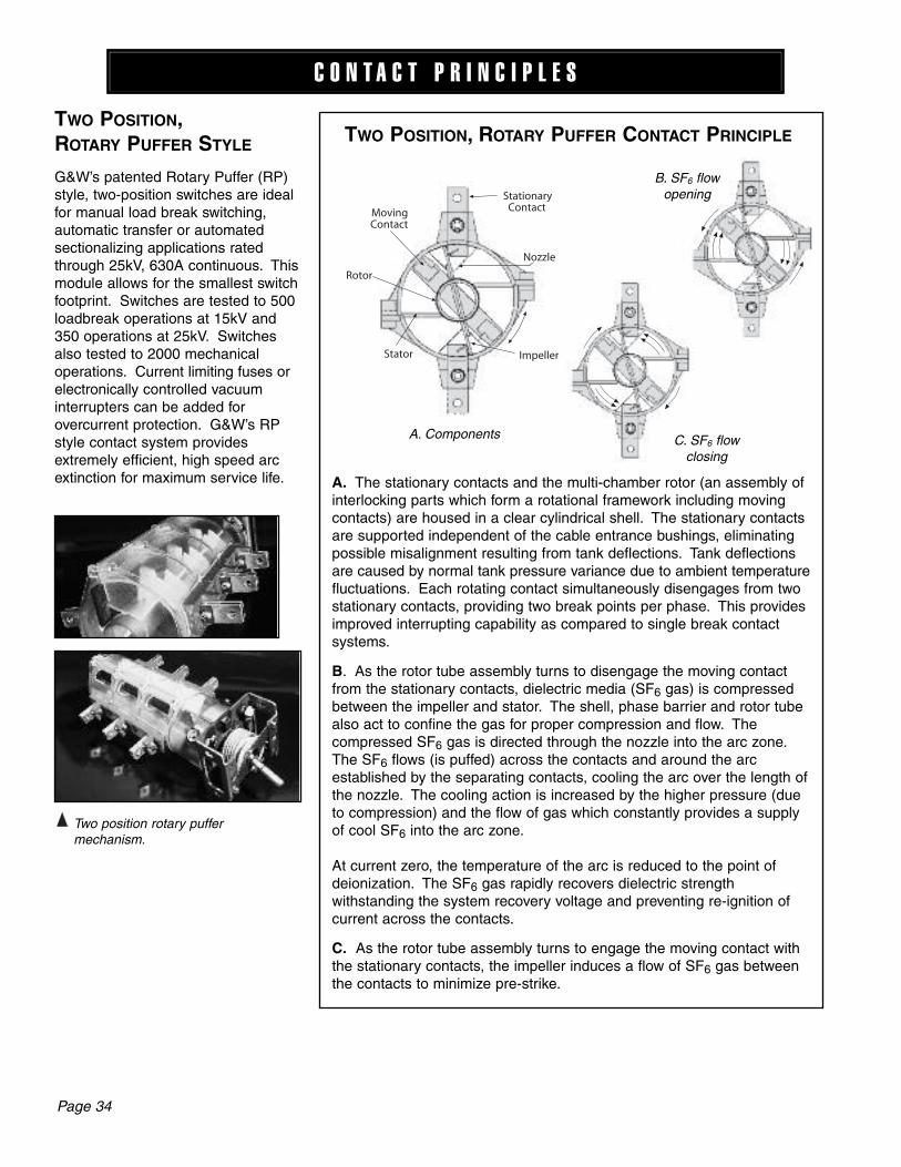
TWO POSITION, ROTARY PUFFER CONTACT PRINCIPLE
A. The stationary con tacts and the multi-cham ber rotor (an as sem bly ofin ter lock ing parts which form a ro ta tion al frame work including movingcon tacts) are housed in a clear cy lin dri cal shell. The sta tion ary contactsare supported in de pen dent of the cable en trance bush ings, elim i nat ingpossible mis align ment re sult ing from tank de flec tions. Tank de flec tionsare caused by normal tank pressure variance due to ambient tem per a turefluc tu a tions. Each rotating contact si mul ta neous ly dis en gag es from twostationary contacts, pro vid ing two break points per phase. This pro videsimproved interrupting ca pa bil i ty as compared to single break contact sys tems.
B. As the rotor tube assembly turns to disengage the moving contactfrom the stationary con tacts, di elec tric media (SF6 gas) is compressedbetween the impeller and stator. The shell, phase barrier and rotor tubealso act to confine the gas for proper compression and flow. The com pressed SF6 gas is directed through the nozzle into the arc zone.The SF6 flows (is puffed) across the contacts and around the arc es tab lished by the sep a rat ing contacts, cooling the arc over the length ofthe nozzle. The cooling action is in creased by the higher pressure (dueto com pres sion) and the flow of gas which con stant ly provides a supplyof cool SF6 into the arc zone.
At current zero, the tem per a ture of the arc is reduced to the point ofdeionization. The SF6 gas rapidly recovers dielectric strength with stand ing the system recovery voltage and preventing re-ignition ofcurrent across the contacts.
C. As the rotor tube assembly turns to engage the moving contact withthe stationary con tacts, the impeller induces a flow of SF6 gas betweenthe contacts to min i mize pre-strike.
G&W’s patented Rotary Puffer (RP)style, two-position switches are idealfor manual load break switching, automatic transfer or au to mat ed sectionalizing applications ratedthrough 25kV, 630A con tin u ous. Thismodule allows for the smallest switchfootprint. Switches are tested to 500loadbreak operations at 15kV and350 operations at 25kV. Switchesalso tested to 2000 mechanical operations. Current limiting fuses orelec tron i cal ly con trolled vacuum in ter rupt ers can be added for over cur rent pro tec tion. G&W’s RPstyle contact system provides ex treme ly efficient, high speed arcextinction for max i mum service life.
TWO POSITION, ROTARY PUFF ER STYLE
C O N T A C T P R I N C I P L E S
Two position rotary puffer mechanism.
A. Components
StationaryContact
Nozzle
ImpellerStator
Rotor
MovingContact
B. SF6 flowopening
C. SF6 flowclosing

Page 35
TWO POSITION,LINEAR PUFFER STYLE
G&W’s patented Linear Puffer (LP)style, two-position switches are idealfor heavy duty manual load breakswitching, automatic transfer or au to mat ed sectionalizing ap pli ca tionsrated through 35kV, 900A con tin u ousand 40kA asymmetrical short circuit.Switches are tested to 1200 loadbreak and 2000 me chan i caloperations. Current limiting fuses orelec tron i cal ly con trolled vacuuminterrupters can be added for overcurrent protection. G&W’s LPstyle contact system provides ex treme ly efficient, high speed arcextinction for max i mum service life.
Stored Energy MechanismLinear puffer switches can be supplied with internal stored energy(cock and trip) mechanisms for boththe open and close operators permitting high speed local or remoteoperation. A separate external triphandle is provided. An optional internal solenoid permits remoteoperation.
C O N T A C T P R I N C I P L E S
Three phase visible position of contacts.
Three phase linear puffer mechanism.
PufferTube
StationaryContact
Nozzle
MovingContactA B C D
OPENOPENINGCLOSED CLOS ING
A. The stationary contact and piston assembly(con tain ing the moving contact and noz zle) arehoused in clear cylindrical tubes. These aremount ed in a modular three-phase as sem blywhich is in de pen dent of the switch tank. The sta tion ary con tacts are sup port ed in de pen dentof the cable entrance bush ings, elim i nat ing pos si ble mis align ment resulting from tank de flec tions. Tank de flec tionsare caused by normal tank pressure vari ance due to ambient tem per a ture fluc tu a tions. This con struc tion elim i nates contact alignmentdifficulties caused by de flec tions of the switch tank walls. The modularcon struc tion also allows testing of the module during assembly andcom plete flex i bil i ty in switch design and con fig u ra tion. The nozzle whichdirects the flow of SF6 has a converging/diverging ge om e try (see photo)which im proves the arc interruption ca pa bil i ty over designs usingstraight throated noz zles. The converging portion of the nozzle has aconstantly de creas ing flow area up to the nozzle throat minimizingvelocity changes in the flow of SF6 gas, while im prov ing arc interruptionand dielectric recovery.
B. As the contacts separate, the SF6 is compressed by the piston as sem bly and directed into the arc zone by the nozzle. The com pressedSF6 flows (is puffed) across the contacts and around the arc es tab lishedby the separating contacts. The cooling action of the gas is in creasedby the higher pressure (due to com pres sion) and the flow which constantly provides a supply of cool SF6 into the arc zone.
C. At current zero the temperature of the arc is reduced to the point ofdeionization, ceasing the flow of current. The SF6 rapidly recoversdielectric strength withstanding the system recovery voltage across the contacts.
D. As the contacts are closing, the piston assembly com press es theSF6 between the contacts. This increases the dielectric strength of thegap, minimizing prestrike. The contacts are designed using a tulip bayo-net construction (see photo). The sliding action of the contacts on en gage ment provides a self clean ing action of the main current carryingsur -fac es. The contact fingers are de signed for increasing contact pres sure with increasing current for proper operation during momentaryor close-into-fault conditions. The contacts have arc resistant coppertungsten tips to minimize erosion of material during load switching andprevent damage to the main current transfer area of the contacts.
TWO POSITION, LINEAR PUFFER CONTACT PRINCIPLE

3-1/C, 600A / 900A APPARATUS BUSHINGSBushings are designed to IEEE 386 stan dards with standard interface ac cept ingcon ven tion al elbow style con nec tors and include an aluminum conductor with5/8"-11 alu mi num thread ed stud and aluminum single hole pad for a 600A rating (elbows must be or dered sep a rate ly). A copper conductor is availablewhich extends the continuous current rating to 900A. For bottom entry switch es, rec om mend ed switch frame height is 42" for all voltages. Weldedflange bushings are avail able.
Page 40
3-1/C, 600A QUIK-CHANGE APPARATUS BUSHINGSCable entrance bushings can be damaged at any time due to im prop er handling, ac ci den tal shifting during shipment, elbow failure or even normal wear and tear.In the case of SF6 gas insulated switches where the tank is totally welded,
con ven tion al bushing re place ment means send ing the switch back to the factoryfor repair. G&W’s exclusive Quik-Change Disconnectable Bushing permits quick,easy field replacement without having to open the switch tank.
Bushings are designed to IEEE 386 stan dards with standard interface accepting con ven tion al elbow style con nec tors and include an aluminum conductor with5/8"-11 alu mi num thread ed stud and aluminum single hole pad (elbows must beor dered sep a rate ly). Copper studs are available. For bot tom entry switch es,rec om mend ed switch frame height is 42" for all voltages.
A C C E S S O R I E S A N D O P T I O N S
3-1/C, 600A VOLTAGE SENSING BUSHINGSG&W’s Voltage Sensing Bushing (VSB) system is a temperature compensated, built-in, voltage measuring system that eliminates the need forPTs when three phase analog voltage monitoring is required. Compared topotential transformers, the VS bushing system offers these benefits: • Significant cost savings • Cleaner, less cumbersome installation • Less space required • Fewer add-on components which could potentially fail • Installed and tested prior to shipment • Can be field calibrated • One digital output per way for threshold voltage detection
The VS bushing system utilizes a capacitively coupled screen which is embedded within the epoxy bushing. The low energy output of the screen isamplified by integral circuitry, resulting in a 0-120 VAC analog output suitable fordirect connection to any relay, IED or RTU. The circuitry incorporates built-in calibration and temperature compensation which improve accuracy.
Bushings are designed to IEEE 386 stan dards with standard interface acceptingcon ven tion al elbow style con nec tors and include an aluminum conductor with 5/8"-11 alu mi num thread ed stud and aluminum single hole pad(elbows must be or dered sep a rate ly). Bushings are bolt-on style. Copperstuds are available. For bot tom entry switch es, rec om mend ed switch frameheight is 42" for all voltages.
SPECIFICATIONSOperating temperature: -40°C to +65°C
Input voltage range (phase-to-phase): 10.7kV - 38kV
Nominal output voltage: 120 VAC
Analog voltage outputs: 3 or 6Number of digital outputs: 1 or 2Digital pick-up voltage: 90% of Vnom (on all phases)
Digital drop-off voltage: 75% of Vnom (on any phase)
Maximum burden (per output): 0.06VAVoltage accuracy: +/- 2% from 0°C to 65°C and +/- 5% from -40°C to 0°C.
Voltage signal delay: 1/2 cycle max

Page 41
A C C E S S O R I E S A N D O P T I O N S
3-1/C, 600A APPARATUS BUSHINGSWELDED FLANGE STYLE
Bushings are designed to IEEE 386 stan dards with standard interface ac cept ingcon ven tion al elbow style con nec tors. Bushings include a stainless steel flange andan aluminum conductor with 5/8"-11 alu mi num thread ed stud. Elbows must beor dered sep a rate ly. 200A deepwell welded flange bushings are also available.
3-1/C, 200A DEEPWELL BUSHINGSBushings are designed to IEEE 386 stan dards with stan dard interface ac cept ingdeadbreak or loadbreak inserts and con ven tion al el bow con nec tors (inserts andelbows must be ordered sep a rate ly). A copper conductor is standard. Forbottom entry switch es, rec om mend ed switch frame height is 42" for all voltages.Welded flange bushings are avail able.
3-1/C, 600A UNIVERSAL BUSHINGSThe combination Universal Cable End and Universal bushing provides anextremely versatile interface between cable and equipment for easy con nect ing,disconnecting, and isolating of distribution cable circuits. End caps for both bushing and splice module permit dead-ending of the cable and equipment forfast cable sectionalizing if required.
Universal bushings are de signed to ac cept G&W uni ver sal bush ing cable ends(G&W Uni ver sal bush ing cable ends must be or dered sep a rate ly. See chartbe low). An alu mi num con duc tor and alu mi num single hole pad is stan dard. Forbot tom entry switch es, rec om mend ed switch frame height is 36" for all volt ag es.Hi-pot test kits are avail able.
NOTE: Universal bushings can accept up to two G&W Universal bushing cableends per phase. For applications requiring this feature, consult factory.
UNIVERSAL BUSHING CABLE ENDS (PER PHASE)Complete cable data required before or der can be pro cessed.
Terminate 1 cable per phase 15CE 27CE
Terminate 2 cables per phase 15CE-CE 27CE-CE
Dead End Kit 15DCE 27DCE
Change 1 cable per phase 151V2 271V2 to 2 cables per phase*
Change 2 cables per phase 152V1 272V1
Configuration Catalog Number
15.5kV 27kV
*Kit includes second cable end(CE) and hardware necessary forconnection.
For standard components, refer to typical specifications at www.gwelec.com under Support.
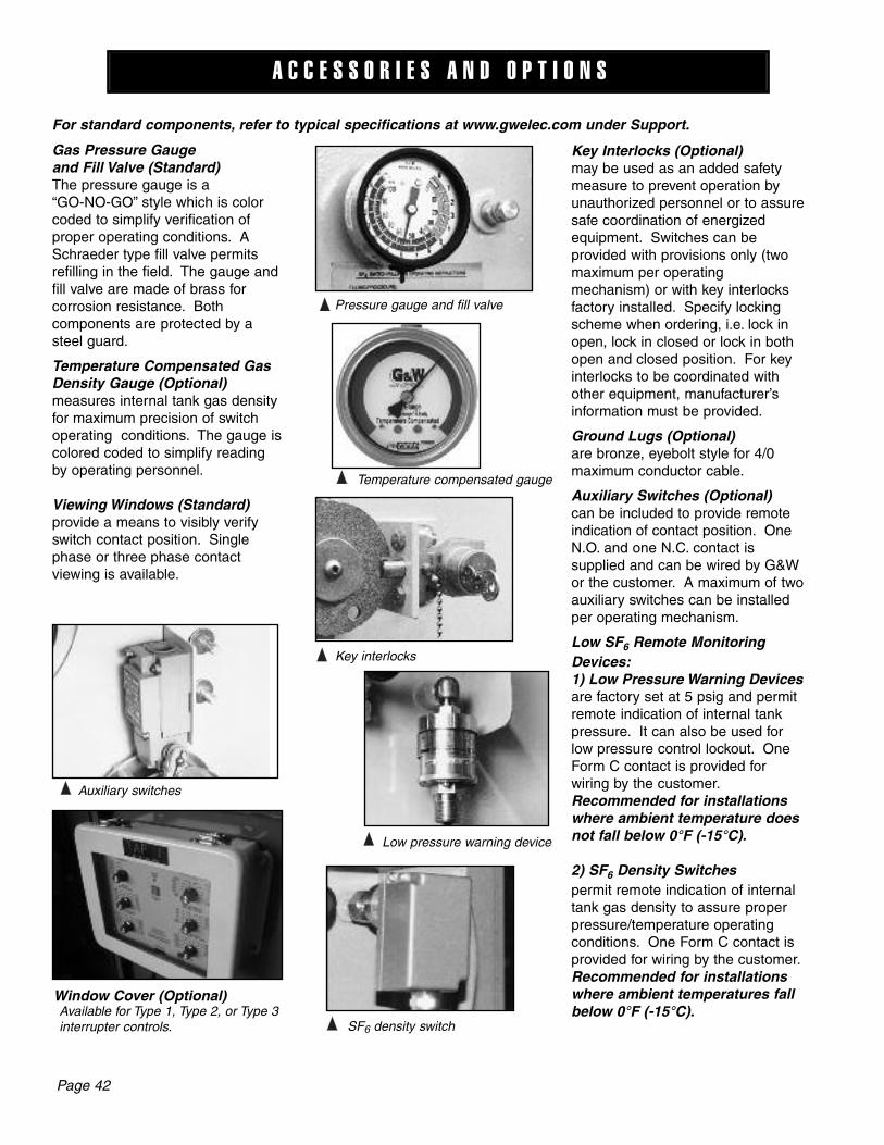
Gas Pressure Gaugeand Fill Valve (Standard)The pressure gauge is a “GO-NO-GO” style which is colorcoded to simplify verification ofproper operating conditions. ASchraeder type fill valve permitsrefilling in the field. The gauge andfill valve are made of brass for corrosion re sis tance. Both components are pro tect ed by asteel guard.
Temperature Compensated GasDensity Gauge (Optional)measures internal tank gas densityfor maximum precision of switchoperating conditions. The gauge iscolored coded to simplify readingby operating personnel.
Viewing Windows (Standard)provide a means to visibly verifyswitch contact position. Singlephase or three phase contact viewing is available.
Key Interlocks (Optional)may be used as an add ed safetymea sure to prevent op er a tion by un au tho rized per son nel or to as suresafe co or di na tion of en er gizedequipment. Switch es can be provid ed with pro vi sions only (twomax i mum per op er at ing mech a nism) or with key interlocksfac to ry installed. Specify lockingscheme when or der ing, i.e. lock inopen, lock in closed or lock in bothopen and closed position. For keyinterlocks to be co or di nat ed withother equipment, manufacturer’s in for ma tion must be provided.
Ground Lugs (Optional)are bronze, eyebolt style for 4/0maximum con duc tor cable.
Auxiliary Switches (Optional)can be included to provide remotein di ca tion of contact po si tion. OneN.O. and one N.C. contact is supplied and can be wired by G&Wor the cus tom er. A max i mum of twoaux il ia ry switch es can be in stalledper operating mechanism.
Low SF6 Remote MonitoringDevices:1) Low Pressure Warning Devicesare factory set at 5 psig and permitremote indication of internal tankpressure. It can also be used forlow pressure control lockout. OneForm C contact is provided forwiring by the customer.Recommended for installationswhere ambient temperature doesnot fall below 0°F (-15°C).
2) SF6 Density Switchespermit remote indication of internaltank gas density to assure properpressure/temperature operatingconditions. One Form C contact isprovided for wiring by the customer.Recommended for installationswhere ambient temperatures fallbelow 0°F (-15°C).
Pressure gauge and fill valve
Temperature compensated gauge
Key interlocks
Low pressure warning device
SF6 density switch
Auxiliary switches
Page 42
A C C E S S O R I E S A N D O P T I O N S
Available for Type 1, Type 2, or Type 3interrupter controls.
Window Cover (Optional)

G & W E L E C T R I C P A G E 1
G&W Overcurrent cOntrOlsThe overcurrent control monitors the current and sends a trip signal which opens the vacuum interrupters and inter-rupts the fault current. G&W controls are self-powered from the current transformers (CTs) located inside the switch. Controls can also be equipped to accept a trip input from another device, such as a transformer over-pressure sensor.
The standard control enclosure for padmount applications is fiberglass NEMA 4X (IP56) rated. An optional NEMA 6P (IP67) rated enclosure is available for applications where the possibility of flooding or short term submersion is possible. Optional enclosures and control designs are available for applications where short or long term sub-mersion is possible.
OperatiOnLoad and fault current are sensed by current transformers mounted internally around each bushing of the switch. The CTs also provide power to the control thus eliminating the need for an external power supply. Approximately 6-10 Amps per phase of load current is required for self power-ing. If not present, the control is in sleep mode. The control will power-up and trip once that load is present (either normal load or during a fault). There will be an approximate 1/2 cycle delay for power-up in this case. In addition, a “READY” light is provided which flashes when the control is powered up by sufficient load current on the sensing CTs, or when the control is provided with external power. The incoming load or fault current is converted to a digital signal. The control constantly compares the measured current to the Time Current Characteristic (TCC) curve programmed into the memory. Based on the programmed settings, the
control determines when to trip open the vacuum inter-rupter to interrupt the fault. All trip set-tings are in Minimum Trip Amperes. An approximate con-version of minimum trip to approximate fuse equivalent is provided. The VI Control can be test-ed in the field using primary or second-ary current injection.
G&W cOntrOl OptiOnsType 1 controls operate three, single phase vacuum interrupting mechanisms. The Type 1 can be field set for either single phase or three phase trip mode. It is used on switches with either single phase reset or three phase reset handles. When in the three phase mode, all three phases trip if the selected trip level of any individ-ual phase is reached. Trip level selections can be made under load or no-load conditions with current ranges in 12 selectable levels. Two ranges of minimum trip settings are available, 15 to 300 Amps and 30 to 600 Amps. Each unit is pre-programmed with 30 user selectable Time Current Characteristic (TCC) curves. The curve selec-tion can be set or changed while the switch is energized.
An 8 pole dip switch allows the user to choose the TCC that best matches their individual coordination require-ments. A label provides a key for the dip switch settings. The control can be factory preset to meet the user’s requirements. As protection or coordination requirements change, settings can easily be changed while the switch is energized. Pressing the manual trip button when the control is powered up electronically trips all three phas-es of the vacuum interrupter. Each control also includes “Last Cause of Trip” LEDs. These LEDs indicate which phase experienced an overcurrent condition, or that the control was given an external or manual trip command.
p Type 1 control
Vacuum Interrupter Overcurrent Controls
p Example of TCC curve

G & W E L E C T R I C P A G E 2
Type 2 controls provide a user friendly interface for quick and easy programming. Trip level selections can be made under load or no-load conditions with current ranges in 12 selectable levels. Two ranges of minimum trip settings are available, 15 to 300 Amps and 30 to 600 Amps. Each unit is pre-programmed with 30 user selectable Time Current Characteristic (TCC) curves. The curve selection can be set or changed while the switch is energized.
An 8 pole dip switch allows the user to choose the TCC curve that best matches their specific coordination re-quirements. The control can be factory preset to meet the user’s requirements. As protection or coordination require-ments change, settings can easily be changed in the field. Pressing the manual trip button when the control is pow-ered up trips all three phases of the vacuum interrupter. Each control also includes “Last Cause of Trip” LEDs. These LEDs indicate what caused the control to issue a trip command - an over current condition, Ground Fault, Instantaneous, or an external or manual trip command.
Since the control is three phase only, one minimum trip level for all three phases is set via a single selector knob. The control has a built-in, adjustable phase time delay. The control also provides a ground fault (phase imbal-ance) feature with adjustable trip and time delay settings as well as instantaneous trip and inrush restraint features.
Features OF type 2 cOntrOlPhase Time DelayFor applications requiring coordination with other protec-tion devices, the Type 2 provides field selectable phase
time delay capability. The phase time delay selector switch provides a phase delay range from 0 to 0.50 sec-onds before the programmed TCC time is initiated. This permits the user to select which protective device will trip the circuit first. The phase time delay allows sectionalizing schemes to be implemented while maintaining full line capacity throughout the circuit.
Ground Fault (Phase Imbalance)The ground fault or phase imbalance feature continu-ously checks for phase imbalance or unequal currents in each of the three phases. Protection from this condition is a common requirement for large three phase motors or other sensitive loads. The ground fault trip current can beadjusted in the field by the user and is represented on the control panel as a percent (%) of the user programmed phase overcurrent minimum trip level. A time delay minimizes nuisance tripping caused by temporary phase imbalances. The Minimum Trip selector sets the desired trip level in amperes depending upon the desired protec-tion scheme. The ground trip feature protects against high impedance faults and loss of phase.
Instantaneous TripThe instantaneous trip multiplier aids in customizing the protection capabilities of the Type 2 control. The rotary switch has nine positions. The first position, OFF, disables this feature. The other positions (x1, x3, x5, x7, x9, x11, x13, and x15) affect how the Type 2 calculates the trip time for overcurrent conditions. When any phase exceeds the current value defined by the minimum trip setting times the instantaneous trip multiplier, the Type 2 will initi-ate a trip command to all three phases within half a cycle, 8.3 msec at 60 Hz (10 msec at 50 Hz).
Inrush RestraintThe inrush restraint function is helpful in preventing nui-sance trips due to cold load pickup. The inrush restraint function is active when the Type 2 is initially powered up and will reactivate if the average three phase primary cur-rent drops below 7.5 Amps (15-300 Amp controls) or 15 Amps (30-600 Amp controls). The inrush restraint function consists of two selectable parameters, the Inrush Trip Multiplier (x1, x2, x3, x4, x5, x6, x7, x8, x9, x11, x13, and x15) and the Inrush Time Delay (0.00, 1.75, 3.25, 5.25, and 7.00 seconds).
The inrush trip multiplier increases the minimum trip value for the selected inrush time delay duration.
Type 2 Control
p Type 2 control
G & W E L E C T R I C P A G E 3
p Type 7 control programming port
Type 7 controls provide the same protection features and options as the Type 3 and 4 controls. For vault and subsurface applications, utilizing Trident® solid dielectric switchgear, G&W recommends the Type 7 control. The Type 7 is mounted within the switch’s mechanism hous-ing and has an IP68 rating for long term submersion. This eliminates the need for a separate control enclosure and associated cabling. The control is programmed using a notebook computer. A notebook computer programming kit is available.
prOGramminG KitFor Type 3, Type 4 or Type 7 Provides software and cable connection to a notebook computer for programming or retrieving fault interrupter control information. The cable connects the USB port of the computer to the control box (Type 3 or 4) or mecha-nism housing (Type 7).
Catalog Number for Type 3, Type 4, Type 7: LPK7-VICSS
p Programming Kit
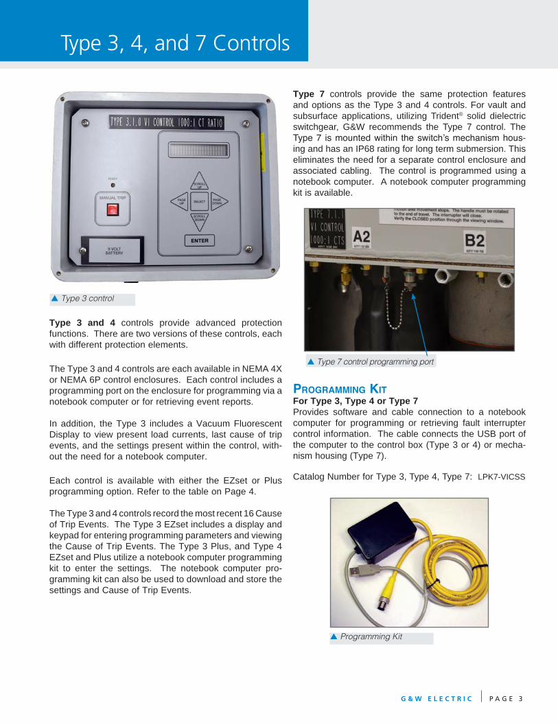
p Type 3 control
Type 3 and 4 controls provide advanced protection functions. There are two versions of these controls, each with different protection elements.
The Type 3 and 4 controls are each available in NEMA 4X or NEMA 6P control enclosures. Each control includes a programming port on the enclosure for programming via a notebook computer or for retrieving event reports.
In addition, the Type 3 includes a Vacuum Fluorescent Display to view present load currents, last cause of trip events, and the settings present within the control, with-out the need for a notebook computer.
Each control is available with either the EZset or Plus programming option. Refer to the table on Page 4.
The Type 3 and 4 controls record the most recent 16 Cause of Trip Events. The Type 3 EZset includes a display and keypad for entering programming parameters and viewing the Cause of Trip Events. The Type 3 Plus, and Type 4 EZset and Plus utilize a notebook computer programming kit to enter the settings. The notebook computer pro-gramming kit can also be used to download and store the settings and Cause of Trip Events.
Type 3, 4, and 7 Controls
G & W E L E C T R I C P A G E 4
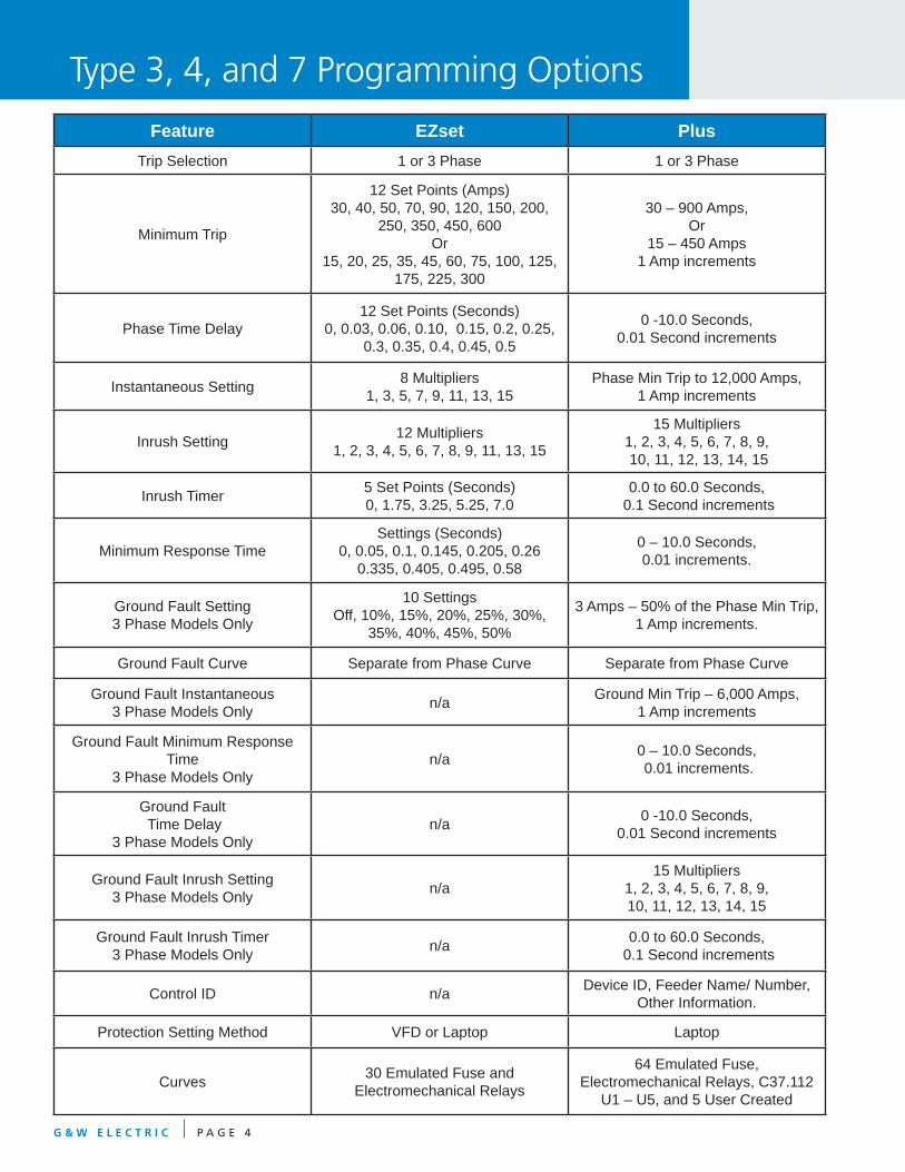
Feature EZset PlusTrip Selection 1 or 3 Phase 1 or 3 Phase
Minimum Trip
12 Set Points (Amps)30, 40, 50, 70, 90, 120, 150, 200,
250, 350, 450, 600Or
15, 20, 25, 35, 45, 60, 75, 100, 125, 175, 225, 300
30 – 900 Amps, Or
15 – 450 Amps1 Amp increments
Phase Time Delay12 Set Points (Seconds)
0, 0.03, 0.06, 0.10, 0.15, 0.2, 0.25, 0.3, 0.35, 0.4, 0.45, 0.5
0 -10.0 Seconds,0.01 Second increments
Instantaneous Setting 8 Multipliers1, 3, 5, 7, 9, 11, 13, 15
Phase Min Trip to 12,000 Amps, 1 Amp increments
Inrush Setting 12 Multipliers1, 2, 3, 4, 5, 6, 7, 8, 9, 11, 13, 15
15 Multipliers1, 2, 3, 4, 5, 6, 7, 8, 9, 10, 11, 12, 13, 14, 15
Inrush Timer 5 Set Points (Seconds)0, 1.75, 3.25, 5.25, 7.0
0.0 to 60.0 Seconds, 0.1 Second increments
Minimum Response TimeSettings (Seconds)
0, 0.05, 0.1, 0.145, 0.205, 0.260.335, 0.405, 0.495, 0.58
0 – 10.0 Seconds, 0.01 increments.
Ground Fault Setting3 Phase Models Only
10 SettingsOff, 10%, 15%, 20%, 25%, 30%,
35%, 40%, 45%, 50%
3 Amps – 50% of the Phase Min Trip, 1 Amp increments.
Ground Fault Curve Separate from Phase Curve Separate from Phase Curve
Ground Fault Instantaneous3 Phase Models Only n/a Ground Min Trip – 6,000 Amps,
1 Amp increments
Ground Fault Minimum Response Time
3 Phase Models Onlyn/a 0 – 10.0 Seconds,
0.01 increments.
Ground Fault Time Delay
3 Phase Models Onlyn/a 0 -10.0 Seconds,
0.01 Second increments
Ground Fault Inrush Setting3 Phase Models Only n/a
15 Multipliers1, 2, 3, 4, 5, 6, 7, 8, 9, 10, 11, 12, 13, 14, 15
Ground Fault Inrush Timer3 Phase Models Only n/a 0.0 to 60.0 Seconds,
0.1 Second increments
Control ID n/a Device ID, Feeder Name/ Number, Other Information.
Protection Setting Method VFD or Laptop Laptop
Curves 30 Emulated Fuse and Electromechanical Relays
64 Emulated Fuse, Electromechanical Relays, C37.112
U1 – U5, and 5 User Created
Type 3, 4, and 7 Programming Options

Product Specification
Power Requirements Powered by current from the current transformers
External Power Requirements (optional)
12-24 VDC (Standard), 48VDC, 120VAC, 220VAC
Type 1 or 2 Minimum Trip Setting Options (500:1 CT)
15A, 20A, 25A, 35A, 45A, 60A, 75A, 100A, 125A, 175A, 225A, 300A
Type 1 or 2 Minimum Trip Setting Options (1000:1 CT)
30A, 40A, 50A, 70A, 90A, 120A, 150A, 200A, 250A, 350A, 450A, 600A
Type 3, 4, of 7 Minimum Trip Setting Options
See table page 4
Enclosure NEMA 4X or optional NEMA 6P
Frequency 60 Hz (Standard)50 Hz (Optional)
Environment Operating Temperature: -40ºC to +65ºCStorage Temperature: -50ºC to +85ºCHumidity: 10% to 95%
type tests:Electrostatic Discharge test IEC 60255-22-2 Level 4 contact discharge
Radiated Electromagnetic Field Disturbance test
IEC 60255-22-3 Level 3
Radiated Electromagnetic Interference
IEEE C37.90.2-1995 - 35V/m
Surge Withstand IEEE C37.60
Vibration IEC 60255-21-1 First Edition – 1988 (EN 60255-21-1 First Edition – 1995)Electrical relays, Part 21: Vibration, shock, bump, and seismic tests on measuring relays and protection equipment; Section One – Vibration tests (sinusoidal); Severity: Class 1 Endurance; Class 2 Response.
IEC 60255-21-2 First Edition – 1988 (EN 60255-21-2 First Edition – 1995)Electrical relays, Part 21: Vibration, shock, bump, and seismic tests on measuring relays and protection equipment; Section Two – Shock and Bump tests. Severity Level: Class 1 Shock withstand, Bump; Class 2 Shock Response
G&W Electric Company305 W. Crossroads PkwyBolingbrook, IL 60440-4938 USATel 708.388.5010 Fax 708.388.0755www.gwelec.comISO 9001: 2008 CertifiedISO 14001:2004 Certified
Catalog VI-12December, 2012

Page 43
� Stainless steel tank, type 304
� Stainless steel enclosure, type 304 or 316
� Temperature compensating pressure gauge
� Low pressure warning device
� SF6 density switch
� 4/0 brass ground lug
� Key interlock provisions
� Key interlocks to lock in open position
� Current transformers for load break ways
� Potential transformers for voltage monitoring and/or control power
� Au to mat ic transfer control type ATC451-4
� Motor actuators for remote switch operation
� Auxiliary switches for remote switch position indication
� Stationary switch controls for remote switch operation and SCADA integration
� Portable switch controls for remote switch operation
� Remote terminal units and communication packages for SCADA integration
� Operation counters
� Voltage sensors with 120 VAC output or a contact to indicate presence of voltage
� 200A deepwell bushings
� 600A apparatus bushings
� 600A voltage sensing bushings
� 600A Quik-Change apparatus bushings
� 600A Universal bushings (through 25kV)
� Type 2 vacuum interrupter control including ground fault trip and time delay selector switches
(three phase only)
� Type 3 vacuum interrupter control including ground fault trip, inrush restraint, programmable
vacuum fluorescent display (VFD) and RS232/485 port
� Type 4 vacuum interrupter control (same as Type 3 with laptop programming only)
� Clear window cover for Type 1, Type 2, or Type 3 interrupter controls
� Submersible NEMA 6P enclosure for vacuum interrupter control
� SEL relays including 751A, 501, 551 and others
� External power / trip for vacuum interrupter control
� Refill kit consisting of regulator, hose and SF6 bottle
A C C E S S O R I E S A N D O P T I O N S
OPTIONSSelect from the following options and add to the appropriate switch specification: