sg26 & sg30 stump grinder - talet attachments · mounting the stump grinder to most skid-steer...
TRANSCRIPT

800-456-7100 I www.paladinlcg.com 503 Gay Street, Delhi, IA 52223, United States of America
SERIALNUMBER:___________________ ManualNumber:OM678 PartNumber:75578 MODELNUMBER:___________________ Rev.4
OPERATOR’SANDPARTSMANUAL
SG26&SG30STUMPGRINDER
9761 1-22-10-5
UNIVERSAL SKID STEER APPLICATIONS


TABLE OF CONTENTS
97831-31-07-2
TO THE OWNER ............................................................................................. ASAFETY PRECAUTIONS ............................................................................... B GeneralInformation ToTheOperator BeforeYouStart WorkingWithTheStumpGrinder TransportingTheStumpGrinder Maintenance
INTERNATIONAL SYMBOLS ......................................................................... CPREOPERATION ............................................................................................ D BeforeOperation SkidSteer Nomenclature
STUMP GRINDER ASSEMBLIES .................................................................. E StumpGrinderAssembly#100318 RearGuardAssembly#101742 WheelAssemblies HydraulicValveAssembly#100982 ControlValveReplacementParts StandardFlowDriveAssembly#100415 HighFlowDriveAssembly#100417 PowerandReturnCircuit CylinderAssembly#100324 CylinderAssembly#101245 ElectricalSchematics-ControlHandles(#104367-Direct𙞰-usewith#101096) ElectricalSchematics-WiringHarness's(#101096-14Pin,#108035-8Pin𚘄-14PinJD)
INSTALLATION INSTRUCTIONS ....................................................................FOPERATING INSTRUCTIONS .......................................................................GLUBRICATION ................................................................................................ HMAINTENANCE ...............................................................................................L Daily/Every40Hours ReplacingTeeth ReplacingHydraulicMotor ReplacingGearbox/MotorCoupler ReplacingGearbox CylinderSealReplacement
STORAGE AND TRANSPORTING ................................................................MTROUBLESHOOTING .................................................................................... NBOLT TORQUE SPECIFICATION ..................................................................OSPECIFICATIONS ........................................................................................... PDECALS ..........................................................................................................QPREDELIVERY CHECKLIST .......................................................................... RLIMITED WARRANTY .................................................................................... S

THIS PAGEIS INTENTIONALLY
BLANK
TO THE OWNERAA
89153-5-03
GENERAL COMMENTS
Congratulations on the purchase of your new BRADCO product! Thisproduct was carefully designed and manufactured to give you years of dependableservice. Only minor maintenance (such as cleaning and lubricating) is required tokeep it in top working condition. Be sure to observe all safety precautions andmaintenance procedures, as described in this manual.
ABOUT THIS MANUAL
This manual has been designed to help you do a better, safer job. Read thismanual carefully and become familiar with its contents. Remember, never letanyone operate this unit without reading the "Safety Precautions" and"Operating Instructions" sections of this manual. (See Sections B and Grespectively.)
Unless noted otherwise, right and left sides are determined from the positionof the operator when behind the product facing forward.
SAFETY ALERT SYMBOL
This is the "Safety Alert Symbol" used by this industry. This symbol isused to warn of possible injury. Be sure to read all warnings carefully.They are included for your safety and for the safety of others workingwith you.
SERVICE
When servicing your product, remember to use only manufacturer replace-ment parts. Substitute parts may not meet the standards required for safe, depend-able operation.
To facilitate parts ordering, record the model and serial number of your unit inthe space provided on this page. This information may be obtained from the identi-fication plate located on the product.
MODEL____________________________________SERIAL NUMBER___________________________DATE PURCHASED_________________________
The parts department needs this information to insure that you receive thecorrect parts for your specific model.

THIS PAGEIS INTENTIONALLY
BLANK

SAFETY PRECAUTIONSB B
TAKE NOTE! THIS SAFETY ALERT SYMBOL FOUND THROUGHOUT THISMANUAL IS USED TO CALL YOUR ATTENTION TO INSTRUCTIONS INVOLV-ING YOUR PERSONAL SAFETY OR OTHERS. FAILURE TO FOLLOWTHESE INSTRUCTIONS CAN RESULT IN INJURY OR DEATH.
THIS SYMBOL MEANS:
ATTENTION!
BECOME ALERT!
YOUR SAFETY IS INVOLVED!
SIGNAL WORDS: Note the use of signal words DANGER, WARNING, andCAUTION with the safety messages. The appropriate signal word for each hasbeen selected using the following guidelines:
DANGER: Indicates an imminently hazardous situation, which if not avoided,will result in death or serious injury. This signal word is to be limitedto the most extreme situations, typically for machine compo-nents which, for functional purposes, cannot be guarded.
WARNING: Indicates a potentially hazardous situation, which if not avoided,could result in death or serious injury, and includes hazards thatare exposed when guards are removed. It may also be used toalert against unsafe practices.
CAUTION: Indicates a potentially hazardous situation, which if not avoided,may result in minor or moderate injury. It may also be used toalert against unsafe practices.
66215-18-95

SAFETY PRECAUTIONSBRADCO STUMP GRINDER
BB
97146-28-04
GENERAL INFORMATIONThis section is composed of various warnings and safety tips. Read and
learn all the information in this section before you attempt to use your BRADCOSTUMP GRINDER. Also read your vehicle owner's manual before using yourequipment. This knowledge will help you operate your unit safely. Do not takethis information lightly, it is presented for your benefit and for the benefit of oth-ers working around you.
The "Safety Alert Symbol" (as described in Section A and at the beginningof Section B) will be used throughout this manual. It will appear with the wordDANGER, WARNING, or CAUTION above it, and a safety message pertaining tothe specific topic being covered. Take the time to read these messages as youcome across them.
TO THE OPERATORThe primary responsibility for safety with the equipment falls to the opera-
tor. Make sure that the equipment is operated only by responsible & competentindividuals with the proper instruction. It is the skill, care, common sense, andgood judgement of the operator that will determine how efficiently and safely thejob is performed. Know your equipment before you start. Know its capabilitiesdimensions, and how to operate all the controls. Visually inspect your equipmentbefore you start and never operate equipment that is not in proper working order.
BEFORE YOU START
1. Read the entire loader and Stump Grinder manual. This knowledge is nec-essary for safe operation.
2. Do NOT operate the standard flow stump grinder on high flow hydraulicsystems. Severe injury could occur due to the increased RPM.
3. Always wear safety goggles and hearing protection during operation, andmake sure ALL safety shields are properly installed.
4. Follow all safety decals. Keep them clean and replace them if they becomeworn, damaged or illegible.
5. Do not paint over, remove or deface any safety signs or warning decals onyour equipment.
6. Know your equipment inside and out. Know how to operate all controlsand know emergency shut down procedures.
7. Keep all stepping surfaces, pedals, and controls free from dirt, grease andoil. Keep equipment clean to help avoid injury from a fall when getting onor off equipment.
8. Use handholds and step plates when getting on/off . Failure to do so couldcause a fall.

SAFETY PRECAUTIONSBRADCO STUMP GRINDER
BB
97156-28-04
9. Never operate the unit near bystanders, traffic, pets, livestock or build-ings. Be sure others know when and where you will be working. Neverdirect discharge towards people, animals or property. Never allow any-one to approach the stump grinder when in operation.
10. Never take passengers on your equipment. There is no safe place for apassenger.
11. Never try to board equipment while it is running.
12. Turn off engine, remove the key and disconnect hydraulic couplersbefore performing maintenance. If unit must be left raised for mainte-nance or any other reason, block the unit securely to prevent accidentalrelease of the lifting mechanism. Serious damage or personal injurycould result.
13. Never leave the unit unattended when in a raised position. Always makesure the attachment is on the ground and keys removed before leavingthe unit unattended.
14. Test all controls before you begin.
15. Do not smoke when refueling. Allow room in the gas tank for expan-sion. Wipe up any spilt fuel. Secure cap tightly when done.
WORKING WITH THE STUMP GRINDER
1. Never operate the unit without first reading and understanding theoperator's manual.
2. Operate the unit only in daylight or sufficient artificial light.
3. Do not carry load with arms in the raised position. Always carry loadsas close as possible to the ground.
4. Check your work area and know where all utility lines are. Avoid hittingunderground electrical wires, cables, pipes, fence posts, gas lines,uneven sidewalk edges, large rocks, etc.
5. Never operate equipment while under the influence of alcohol, prescrip-tion drugs, nonprescription drugs, or illegal drugs which could inhibitphysical and/or mental capacity.
6. Do not exceed rated operating capacity, as machine may become un-stable which may result in loss of control.
7. Do not operate the unit without covers installed.
8. Keep hands, feet, hair and clothing away from equipment with enginerunning. Stay clear of all moving parts.
9. Do not raise the attachment when the grinding wheel is rotating.
10. ALWAYS LOWER THE LOADER ARMS TO THE GROUND, SHUT OFFTHE ENGINE AND REMOVE THE KEY BEFORE GETTING OFF THE UNIT.

SAFETY PRECAUTIONSBRADCO STUMP GRINDER
BB
97166-28-04
TRANSPORTING THE STUMP GRINDER
1. Follow all federal, state and local regulations when transporting the unit onpublic roads.
2. Use extra care when loading or unloading the machine onto a truck ortrailer. Disconnect hydraulic couplers during transportation.
MAINTENANCE
1. Never work on equipment while it is running. Always lower the loaderarms to the ground, shut off the engine, remove the key and disconnecthydraulic couplers before performing maintenance on the unit.
2. Never make hydraulic repairs while the system is under pressure. Injury ordeath could result.
3. Observe proper maintenance schedules and repairs to keep the unit in safeworking order.
4 Always wear safety goggles or glasses when working on equipment.
5. Use only manufacturer recommended replacement parts. Other parts maybe substandard in fit and quality.
WARNING! Escaping fluid under pressure can have sufficient force to penetratethe skin causing serious personal injury. Fluid escaping from a verysmall hole can be almost invisible. Use a piece of cardboard orwood, rather that hands to search for suspected leaks.Keep unprotected body parts, such as face, eyes, and arms as faraway as possible from a suspected leak. Flesh injected with hydrau-lic fluid may develop gangrene or other permanent disabilities.
If injured by injected fluid, see a doctor at once. If your doctor isnot familiar with this type of injury, ask him to research it immedi-ately to determine proper treatment.
CARDBOARD
HYDRAULIC HOSEOR FITTING
MAGNIFYING GLASS

C CINTERNATIONAL SYMBOLS
As a guide to the operation of your equipment, various internationalsymbols have been utilized on the instruments and controls. The symbolsare shown below with an indication of their meaning.
Engine speed Alternator charge
Hours recorded Power take-off (on)
Engine water temperature Power take-off (off)
Lights "Tortoise," slow or minimum setting
Horn "Hare," fast or maximum setting
Engine oil pressure Caution
Hazard warning Control lever operating direction
Axle connect Rock shaft (raised)
Axle disconnect Rock shaft (lowered)
Continuously variable Remote cylinder (extended)
Increase Remote cylinder (retracted)
Decrease Remote cylinder (FLOAT)
Diesel fuel Differential lock
Creeper range Read operators manual
High range Neutral
Low range Forward
Reverse
38694-14-94-2

PREOPERATIONSTUMP GRINDER
DD
97628-6-04
GENERAL INFORMATION
The BRADCO Stump Grinders were designed to be easy to use andmaintain. They are operated by the skid-steer auxiliary hydraulics and mount tothe quick attach mechanism for easy operator hook-up. There are two models ofBRADCO stump grinders available, standard flow and high flow. These will allowmounting the stump grinder to most skid-steer loaders.
Unless noted otherwise, right and left are determined from the position ofthe skid-steer operator sitting in the operator's seat facing forward.
Remember to read the "Safety Precautions" and "Operating Instructions"sections of the manual BEFORE you attempt to install or use the Stump Grinder.
NOTE: Illustrations and data used in this manual were current (according tothe information available to us) at the time of printing, however, we reservethe right to redesign and change the grinders as may be necessary withoutnotification.
BEFORE OPERATION
The primary responsibility for safety with this equipment falls to the opera-tor. Make sure that the equipment is operated only by trained individuals thathave read and understand this manual. Don't hurry the learning process or takethe unit for granted. Practice the operation of your new equipment and becomefamiliar with the controls and the way it handles on your machine.
If there is any portion of this manual or function you do not understand,contact your local authorized dealer or manufacturer.
SKID-STEER
Your skid-steer must be equipped with auxiliary hydraulic and an electriccontrol kit (or the optional electric control handle must be ordered from yourBRADCO dealer).
There are two models of BRADCO stump grinders available, standardflow and high flow. Be sure the stump grinder you have purchased matches thehydraulic flow of your skid-steer.
The standard flow unit requires 15-22 GPM and the high flow requires 25-42 GPM. Operating the high flow stump grinder on a standard flow skid-steer willresult in poor performance.
WARNING! OPERATING THE STANDARD FLOW STUMP GRINDER ON AHIGH FLOW HYDRAULIC SYSTEM MAY CAUSE SEVERE IN-JURY OR DEATH TO THE OPERATOR OR BYSTANDERS DUETO THE INCREASED RPM.

PREOPERATIONSTUMP GRINDER
DD
97638-6-04
NOMENCLATURE
Throughout this manual, reference is made to various stump grindercomponents. The purpose of this page is to acquaint you with the various namesof these components. This knowledge will be helpful when reading through thismanual or when ordering service parts.
MANUAL TUBE
RUBBER REARGUARD
LIFT CYLINDER
MOUNTING BRACKETYOKE
VALVE COVER
WHEEL GUARD COVER
WHEEL
SWING CYLINDER
CONTROL VALVE
STEP
GROUSER PAD
CYLINDER SPEEDCONTROL KNOB
STUMP GRINDERFRAME

STUMP GRINDER ASSEMBLYASSEMBLY #100318
EE
96931-30-07-2
1
2
34 5
6
7
8
9
10
11
12
13
14
15
16
17181920
21
22
23
5
5
5
5
6
10
18
WHEEL GUARD COVER(LOCATED IN GUARD ASSEMBLY)
24

NO REQ'D PARTNO. DESCRIPTION
1 2 1022 .31"UNCX1.00"HexCapscrew 2 4 1513 .31"FlatWasher 3 2 1502 .31"LockWasher 4 2 1225 .31"UNCHexNut 5 7 1953 .38"UNCX.75"FlangeHeadCapscrew
6 2 100769 Pin-1.00"X2.50" 7 1 101245 CylinderAssembly-Lift - 45617 ReplacementSealKit 8 1 25453 ManualTube 9 1 100770 Pin-1.00"X4.00" 10 2 1051 .38"UNCX3.00"HexCapscrew 2 1837 .38"UNCDeformedLockNut
11 1 100379 Pin-1.25"X13.50" 12 1 100322 Yoke 13 1 100378 Pin-1.25"X11.38" 14 1 100420 ValveCover 15 1 100321 MountingBracket
16 1 31990 Pin-1.00"X4.50" 17 1 100324 CylinderAssembly-Swing - 45617 ReplacementSealKit 18 2 6616 GreaseFitting 19 1 100323 StumpGrinderFrame 20 2 1043 .38"UNCX1.00"HexCapscrew 2 1837 .38"UNCDeformedLockNut
21 1 105762 AccessCover 22 2 1939 .25"UNCX.75"FlangeheadHexCapscrew 23 1 101802 BraceStand 24 2 1044 .38"UNCX1.25"HexCapscrew 2 1837 .38"UNCDeformedLockNut
STUMPGRINDERASSEMBLYASSEMBLY#100318
EE
96941-30-07-2
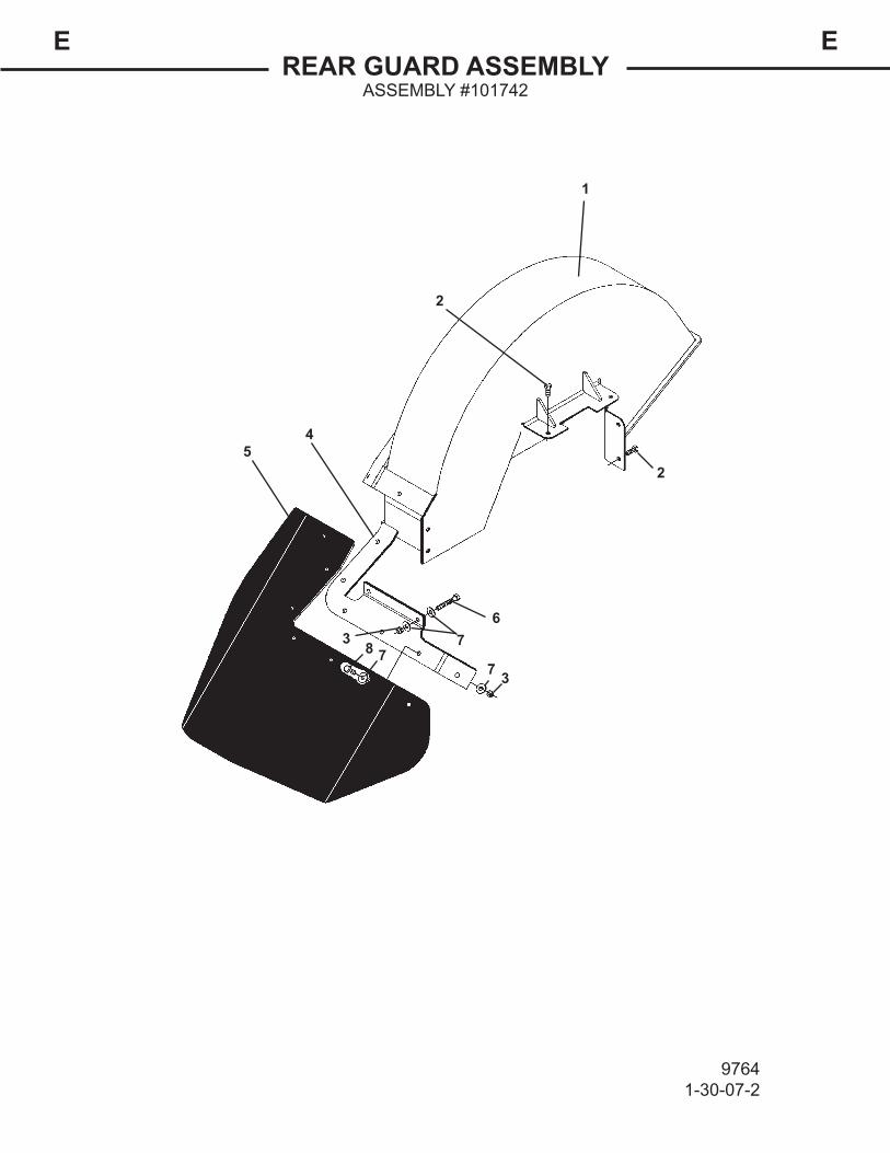
REAR GUARD ASSEMBLYASSEMBLY #101742
EE
97641-30-07-2
1
2
45
673 8
2
77 3

NO REQ'D PARTNO. DESCRIPTION
1 1 102061 WheelGuardCover 2 4 1043 .38"UNCX1.00"HexCapscrew 3 10 1837 .38"UNCDeformedOvalLockNut 4 1 102062 RearRubberGuardBracket 5 1 100802 RubberGuard
6 2 1049 .38"UNCX2.50"HexCapscrew 7 20 1514 .38"FlatWasher 8 8 1044 .38"UNCX1.25"HexCapscrew
REARGUARDASSEMBLYASSEMBLY#101742
EE
97651-30-07-2

SQUARE TOOTH WHEEL ASSEMBLY26" STANDARD FLOW WHEEL ASSEMBLY #101234
30" HIGH FLOW WHEEL ASSEMBLY #100418
EE
97668-9-04
DIRECTION OF ROTATION
1
2
3

NO REQ'D PART NO. DESCRIPTION
1 1 101235 26" Wheel - Standard Flow1 19911 30" Wheel - High Flow
2 28 19917 Square Tooth - Threaded3 28 1810 .62" UNF Deformed Lock Nut
97678-9-04
REPLACEMENT TOOTH KIT #10207528 19917 Square Tooth - Threaded28 1810 .62" UNF Deformed Lock Nut
SQUARE TOOTH WHEEL ASSEMBLY26" STANDARD FLOW WHEEL ASSEMBLY #101234
30" HIGH FLOW WHEEL ASSEMBLY #100418
EE

BOLT-ON TOOTH WHEEL ASSEMBLY26" STANDARD FLOW WHEEL ASSEMBLY #101243
30" HIGH FLOW WHEEL ASSEMBLY #100416
EE
97688-9-04
DIRECTION OF ROTATION
1
3
4
7
7
2
5
6
TWO RIGHTTEETH AT THIS
LOCATION
TWO LEFTTEETH AT THIS
LOCATION
ONE STRAIGHTTOOTH ON LEFTSIDE OF WHEEL
ONE STRAIGHTTOOTH ON RIGHTSIDE OF WHEEL

NO REQ'D PART NO. DESCRIPTION
1 1 102147 26" Wheel - Standard Flow1 19912 30" Wheel - High Flow
2 16 19959 Tooth Mount - Threaded3 15 19957 Right Tooth4 15 19956 Left Tooth5 16 19960 Tooth Mount - Counterbored
6 32 10091 .62" UNF X 2.50" Sockethead Capscrew7 2 19958 Straight Tooth
97698-9-04
REPLACEMENT TOOTH KIT #10207615 19957 Right Tooth15 19956 Left Tooth2 19958 Straight Tooth
BOLT-ON TOOTH WHEEL ASSEMBLY26" STANDARD FLOW WHEEL ASSEMBLY #101243
30" HIGH FLOW WHEEL ASSEMBLY #100416
EE
NOTE: When looking at the left side of the wheel as shown every numberone position is a special set-up. Twelve o'clock set-up is two left teeth;three o'clock is two right teeth; six o'clock is one left tooth and a straighttooth on the right side of the wheel; and nine o'clock is a right tooth and astraight tooth on the left side of the wheel.

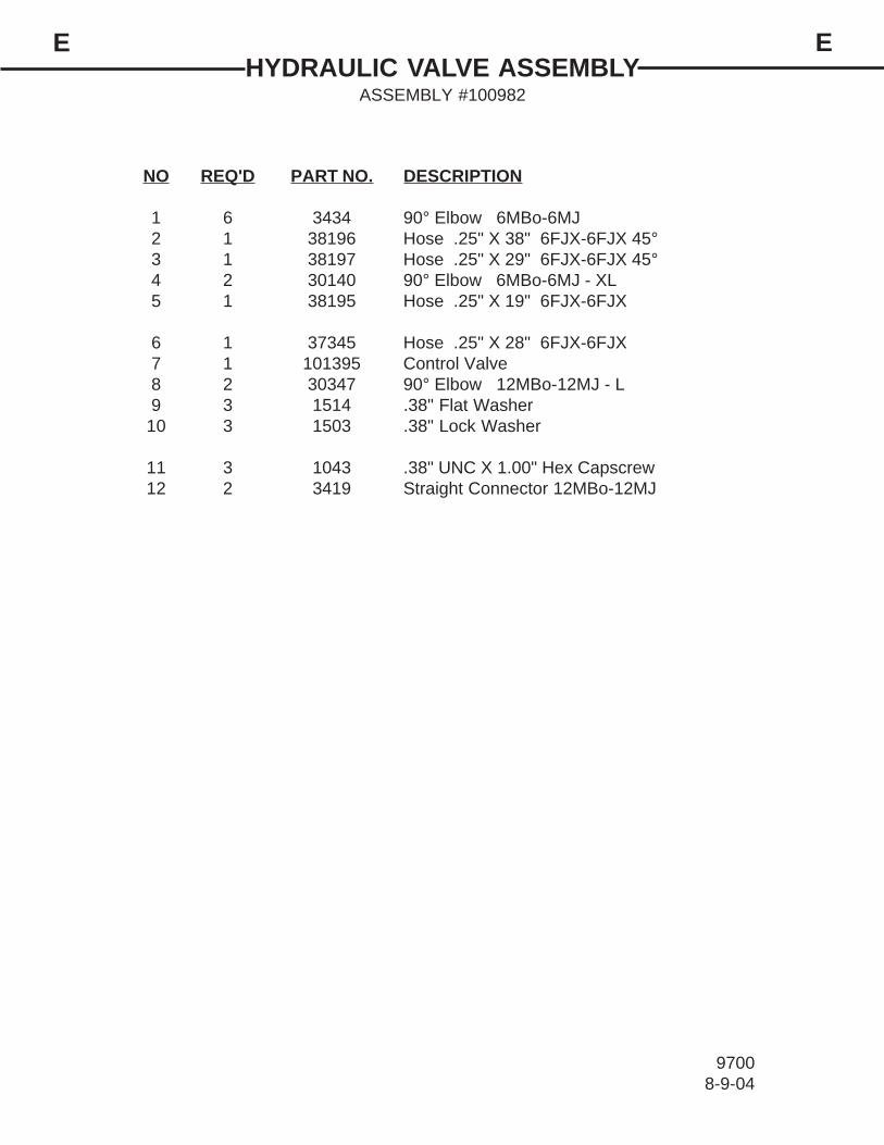
HYDRAULIC VALVE ASSEMBLYASSEMBLY #100982
EE
96998-9-04
1
2
3
4
5
6
7
8
91011 12
1
1
1
4
TO LIFTCYLINDER
TO SWINGCYLINDER
NO REQ'D PART NO. DESCRIPTION
1 6 3434 90° Elbow 6MBo-6MJ2 1 38196 Hose .25" X 38" 6FJX-6FJX 45°3 1 38197 Hose .25" X 29" 6FJX-6FJX 45°4 2 30140 90° Elbow 6MBo-6MJ - XL5 1 38195 Hose .25" X 19" 6FJX-6FJX
6 1 37345 Hose .25" X 28" 6FJX-6FJX7 1 101395 Control Valve8 2 30347 90° Elbow 12MBo-12MJ - L9 3 1514 .38" Flat Washer
10 3 1503 .38" Lock Washer
11 3 1043 .38" UNC X 1.00" Hex Capscrew12 2 3419 Straight Connector 12MBo-12MJ
HYDRAULIC VALVE ASSEMBLYASSEMBLY #100982
EE
97008-9-04

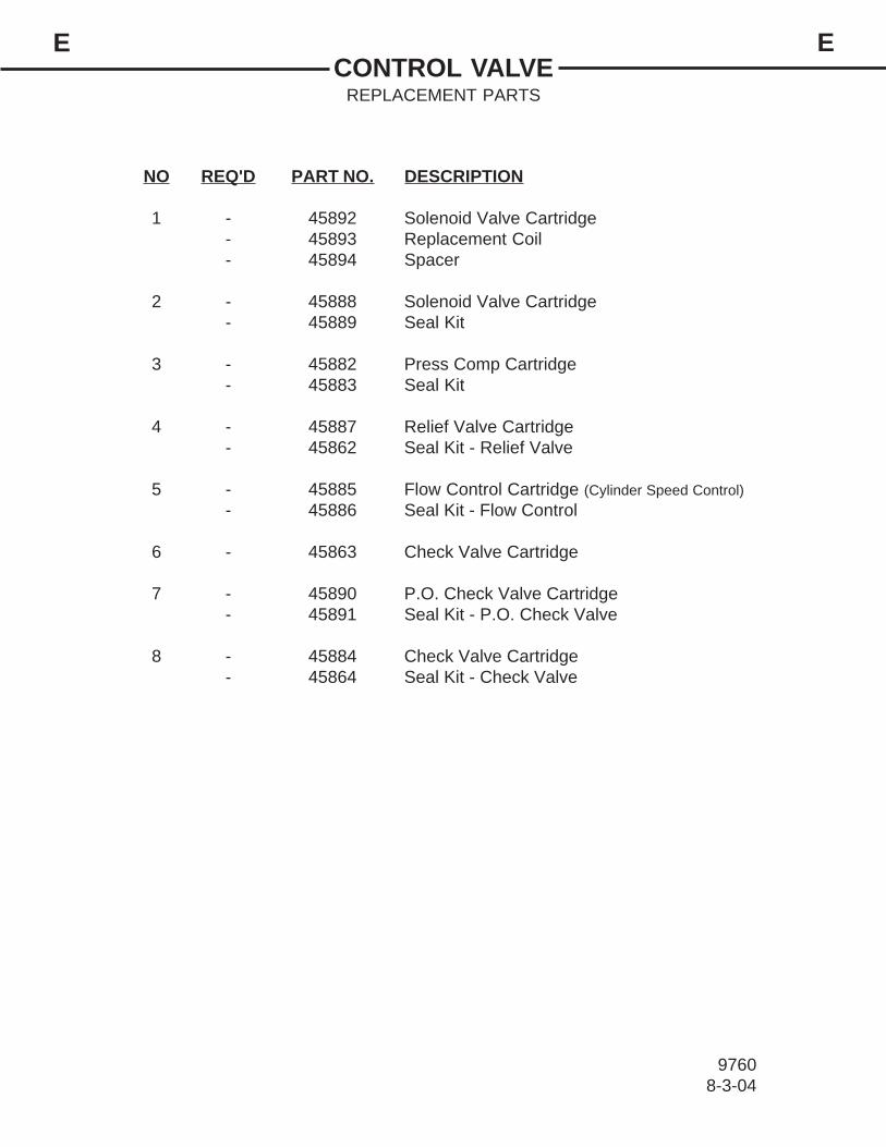
CONTROL VALVEREPLACEMENT PARTS
EE
97598-3-04
12
3
4
5 6
7
8
NO REQ'D PART NO. DESCRIPTION
1 - 45892 Solenoid Valve Cartridge- 45893 Replacement Coil- 45894 Spacer
2 - 45888 Solenoid Valve Cartridge- 45889 Seal Kit
3 - 45882 Press Comp Cartridge- 45883 Seal Kit
4 - 45887 Relief Valve Cartridge- 45862 Seal Kit - Relief Valve
5 - 45885 Flow Control Cartridge (Cylinder Speed Control)- 45886 Seal Kit - Flow Control
6 - 45863 Check Valve Cartridge
7 - 45890 P.O. Check Valve Cartridge- 45891 Seal Kit - P.O. Check Valve
8 - 45884 Check Valve Cartridge- 45864 Seal Kit - Check Valve
CONTROL VALVEREPLACEMENT PARTS
EE
97608-3-04

STANDARD FLOW DRIVE ASSEMBLYASSEMBLY #100415
EE
97016-24-04
1
2
3
4
5
3
6
78
9
10
11
12
13
14
10
12
3
6
TO CONTROLVALVE

NO REQ'D PARTNO. DESCRIPTION
1 2 38232 Hose.62"X52"10MBo90°-12FJX 2 1 17787 HydraulicMotor ** 45814 ReplacementSealKit 3 4 1841 .50"UNCDeformedLockNut 4 1 100860 MotorMount 5 2 1091 .50"UNCX1.75"HexCapscrew
6 2 6886 RubberBumper 7 1 17808 Coupler 8 4 1799 .38"UNCX1.50"SocketheadCapscrew 9 1 22277 RollPin 10 1 100988 RightAngleGearboxAssembly - 19701 ReplacementCastleNut - 19702 ReplacementInputSeal - 19703 ReplacementOutputSeal - 7781 ReplacementBreatherPlug
11 4 1839 .62"UNCDeformedOvalLockNut 12 8 1627 .62"HardFlatWasher 13 4 10071 .62"UNCX2.25"HexCapscrew-Grade8 14 1 1613 CotterPin
STANDARDFLOWDRIVEASSEMBLYASSEMBLY#100415
EE
97021-30-07-2
**Fieldreplacementoftheinternalmotorsealsvoidswarranty.

HIGH FLOW DRIVE ASSEMBLYASSEMBLY #100417
EE
97031-30-07-3
1
23
45
6
7
9
9
10
11
12
13
1415
17
17
18 19
16
1920
TO CONTROL VALVE
21
8

NO REQ'D PARTNO. DESCRIPTION
1 2 38233 Hose.75"X52"12FJX-12FJX 2 1 22600 90°Elbow12MBo-12MJ 3 1 30292 StraightConnector16MBo-12FB 4 1 30051 90°Elbow16MBo-12MJ 5 1 37482 CaseDrainHose.25"X132"6FJX-6FJX 1 38234 CaseDrainHose.25"X148"6FJX-6FJX (NotIncludedinDriveAssembly)
6 1 3269 StraightAdapter8MBo-6MJ (NotIncludedinDriveAssembly) 7 1 84923 MaleCoupler (NotIncludedinDriveAssembly) 8 1 101793 HydraulicMotor ** 45898 ReplacementShaftSealKit ** 45899 ReplacementRearSealKit 9 8 1841 .50"UNCDeformedLockNut 10 1 30388 45°Elbow4MBo-6MJ
11 4 6886 RubberBumper 12 2 101785 MotorMount 13 4 10086 .50"UNCX2.25"Capscrew 14 4 1799 .38"UNCX1.50"SocketheadCapscrew 15 1 100917 Coupler
16 1 22277 RollPin 17 1 101509 RightAngleGearboxAssembly - 19701 ReplacementCastleNut - 102011 ReplacementInputSeal - 102010 ReplacementOutputSeal - 7781 ReplacementBreatherPlug
18 4 1936 .75"UNCDeformedOvalLockNut 19 8 1649 .75"HardFlatWasher 20 4 1140 .75"UNCX2.25"HexCapscrew 21 1 1613 CotterPin
HIGHFLOWDRIVEASSEMBLYASSEMBLY#100417
EE
97041-30-07-3
**Fieldreplacementoftheinternalmotorsealsvoidswarranty.

STANDARD FLOW HOSE SETPOWER AND RETURN CIRCUIT
EE
97056-24-04
1
2
3
4
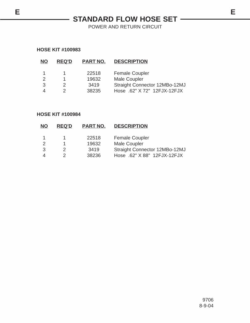
HOSE KIT #100983
NO REQ'D PART NO. DESCRIPTION
1 1 22518 Female Coupler2 1 19632 Male Coupler3 2 3419 Straight Connector 12MBo-12MJ4 2 38235 Hose .62" X 72" 12FJX-12FJX
HOSE KIT #100984
NO REQ'D PART NO. DESCRIPTION
1 1 22518 Female Coupler2 1 19632 Male Coupler3 2 3419 Straight Connector 12MBo-12MJ4 2 38236 Hose .62" X 88" 12FJX-12FJX
STANDARD FLOW HOSE SETPOWER AND RETURN CIRCUIT
EE
97068-9-04

HIGH FLOW HOSE SETPOWER AND RETURN CIRCUIT
EE
97708-9-04
1
2
3
4

HOSE KIT #101754
NO REQ'D PART NO. DESCRIPTION1 1 84921 Female Coupler .62"-12FBo-FF2 1 19636 Male Coupler 62"-12FBo-FF3 2 3419 Straight Connector 12MBo-12MJ4 2 35920 Hose .75" X 73" 12FJX-12FJX
* Case drain hoses and fittings included in this kit are shown on the High Flow DriveAssembly pages.
HOSE KIT #101755
NO REQ'D PART NO. DESCRIPTION1 1 84921 Female Coupler 62"-12FBo-FF2 1 19636 Male Coupler 62"-12FBo-FF3 - ----- NOT USED WITH LONGER HOSE #370604 2 37060 Hose .75" X 88" 12MBo-12FJX
* Case drain hoses and fittings included in this kit are shown on the High Flow DriveAssembly pages.
HOSE KIT #102073
NO REQ'D PART NO. DESCRIPTION1 1 22520 Female Coupler .75"-12FBo-FF2 1 19638 Male Coupler 75"-12FBo-FF3 2 3419 Straight Connector 12MBo-12MJ4 2 35920 Hose .75" X 73" 12FJX-12FJX
* Case drain hoses and fittings included in this kit are shown on the High Flow DriveAssembly pages.
HOSE KIT #102074
NO REQ'D PART NO. DESCRIPTION1 1 84921 Female Coupler 62"-12FBo-FF2 1 19636 Male Coupler 62"-12FBo-FF3 - ----- NOT USED WITH LONGER HOSE #370604 2 37060 Hose .75" X 88" 12MBo-12FJX
* Case drain hoses and fittings included in this kit are shown on the High Flow DriveAssembly pages.
HIGH FLOW HOSE SETPOWER AND RETURN CIRCUIT
EE
97718-9-04

CYLINDER ASSEMBLYASSEMBLY #100324
EE
97217-1-04
1
2
3
4
5
6
7
8
9
10
11
12
13
14
15
16
17

NO REQ'D PART NO. DESCRIPTION
1 2 6616 Grease Fitting2 1 1483 Hex Nut3 1 50252 Piston4 1 88926 Cylinder Tube5 1 77458 Cylinder Gland
6 1 100325 Cylinder Rod7 2 88919 Bushing8 1 4644* Piston Ring9 1 4645* O'Ring
10 1 4641* O'Ring
11 1 5421 Washer12 1 4509* O'Ring13 1 4510* Back-Up Washer14 1 45219* Poly-Pak Seal15 1 45250* O'Ring
16 1 45389* Rod Wiper17 1 88918 Bushing
CYLINDER ASSEMBLYASSEMBLY #100324
EE
97227-1-04
NOTE: Seal Kit #45617 includes all parts marked with an asterisk (*). Partsare not sold separately.
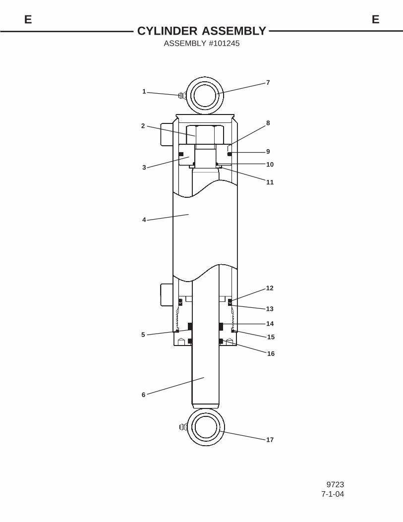
CYLINDER ASSEMBLYASSEMBLY #101245
EE
97237-1-04
1
2
3
4
5
6
7
8
9
10
11
12
13
14
15
16
17

NO REQ'D PART NO. DESCRIPTION
1 2 6616 Grease Fitting2 1 1483 Hex Nut3 1 50252 Piston4 1 101246 Cylinder Tube5 1 77458 Cylinder Gland
6 1 101247 Cylinder Rod7 2 88919 Bushing8 1 4644* Piston Ring9 1 4645* O'Ring
10 1 4641* O'Ring
11 1 5421 Washer12 1 4509* O'Ring13 1 4510* Back-Up Washer14 1 45219* Poly-Pak Seal15 1 45250* O'Ring
16 1 45389* Rod Wiper17 1 88918 Bushing
CYLINDER ASSEMBLYASSEMBLY #101245
EE
97247-1-04
NOTE: Seal Kit #45617 includes all parts marked with an asterisk (*). Partsare not sold separately.

CONTROL BOX ASSEMBLY
9828 3-14-06-3
BRADCO ELECTRICAL CONTROL HANDLE ASSEMBLY #104367(DIRECT CONNECT TO CONTROL VALVE)
CONTROL VALVE
CONTROL HANDLE WITH CORD
CYLINDER SPEEDCONTROL KNOB
G
G
H
H
C
C
D
D
#102329CONTROL BOX WITH CONNECTORS
#17173POWER CONNECTION
30 AMP FUSE
TO SKID-STEER

CONTROL BOX ASSEMBLY
9726 3-15-06-4
OPTIONAL ELELCTRICAL CONTROL BOX ASSEMBLY #104368(USE WITH WIRING HARNESS #101096)
DEUTSCH CONNECTOR PIN DETAILB = BLACK (GROUND)C = DARK GREEN (SWING - LEFT)D = BROWN (SWING - RIGHT)G = ORANGE (LIFT - DOWN)H = YELLOW (LIFT - UP)
DEUTSCH CONNECTOR
#102341CONTROL HANDLE WITH CONNECTORS
#17173POWER CONNECTION
30 AMP FUSE
TO SKID-STEER

ELECTRICAL HARNESS
9709 3-15-06-2
WIRING HARNESS #101096
DEUTSCH CONNECTOR PIN DETAILB = BLACK (GROUND)C = DARK GREEN (SWING - LEFT)D = BROWN (SWING - RIGHT)G = RED (LIFT - DOWN)H = YELLOW (LIFT - UP)
DEUTSCH CONNECTOR
D
CGH
D
C
G
H
CYLINDER SPEED CONTROL KNOB
CONTROL VALVE

ELECTRICAL SCHEMATIC
10887 1-26-06
WIRING HARNESS #108035
DEUTSCH CONNECTOR
C
DBG
C
D
B
G
CYLINDER SPEED CONTROL KNOB
CONTROL VALVE
DEUTSCH CONNECTOR PIN DETAILB = RED (LIFT - DOWN) C = BROWN (SWING - RIGHT) D = DARK GREEN (SWING - LEFT)F = BLACK (GROUND)G = YELLOW (LIFT - UP)

ELECTRICAL SCHEMATIC
10888 1-26-07
WIRING HARNESS #108036
DEUTSCH CONNECTOR PIN DETAILA = BLACK (GROUND)C = DARK GREEN (SWING - LEFT)D = BROWN (SWING - RIGHT)E = YELLOW (LIFT - UP) G = RED (LIFT - DOWN)
DEUTSCH CONNECTOR
D
CGE
D
C
G
E
CYLINDER SPEED CONTROL KNOB
CONTROL VALVE

INSTALLATION INSTRUCTIONSFF
97728-6-04
GENERAL INFORMATIONThe following instructions will help you to mount your stump grinder onto
your skid-steer loader. The stump grinder uses the quick-attach system for easeof installation. Therefore, if you know how to attach your bucket, attaching thestump grinder should prove no problem.
Remember to read all safety warning, decals and operations instructionsbefore operating the attachment. If there is any portion of this manual that you donot understand, contact your dealer.
WARNING! OPERATING THE STANDARD FLOW STUMP GRINDER ON AHIGH FLOW HYDRAULIC SYSTEM MAY CAUSE SEVERE IN-JURY OR DEATH TO THE OPERATOR OR BYSTANDERS DUETO THE INCREASED RPM.
INSTALLATION INSTRUCTIONS
1. Remove any shipping banding from around the stump grinder and skid.
2. Remove any attachment from the front of the loader.
3. Following all standard safety practices and the instructions for installing anattachment on your skid-steer operator's manual, install the stump grinderonto your skid-steer.
NOTE: IT IS IMPORTANT TO MAKE SURE THE LOCKING MECHANISM ONYOUR QUICK ATTACH IS ENGAGED, THEREFORE LOCKING THE ATTACH-MENT ONTO THE SKID-STEER.
4. Lower the unit to the ground and remove the key.
5. If the rear guard assembly was not installed at the factory, install it nowusing the hardware provided. (See Section E for hardware locations.)
6. Relieve any pressure from the auxiliary hydraulic system and after makingsure that there is not any foreign matter on the hydraulic couplers, connectthe couplers to the auxiliary hydraulic system of your skid-steer loader.
7. If installing the high flow stump grinder, connect the case drain coupler tothe case drain on your skid-steer loader. Route the hoses in such a fash-ion as to avoid pinching or chafing.
CAUTION! BE SURE CASE DRAIN COUPLER IS COMPLETELY ENGAGED.IMMEDIATE HYDRAULIC MOTOR SEAL FAILURE WILL OC-CUR IF CASE DRAIN IS NOT SUCCESSFULLY CONNECTED.

INSTALLATION INSTRUCTIONSFF
97207-1-04
8. Route the electrical control handle to the operator's station taking care toavoid pinching of the electrical wire harness. NOTE: If your skid-steer isequipped with a multi-function control handle, connect the electrical wireharness from the stump grinder to the auxiliary electrical connector on thefront of the skid-steer.
9. Following all standard safety practices, start the skid-steer and run allcylinders through their full cycle to purge any air from the system. Checkthat all controls function according to the operating control decal.Your stump grinder is now installed and ready for operation.
DISCONNECT INSTRUCTIONS
1. With the stump grinder extended halfway out, lower the unit onto thegrouser pads on the mounting bracket and the brace stand. NOTE: Ex-tending the unit will help prevent it from tipping forward when discon-nected.
2. Following Safety Shut Down Procedures; stop the engine and set theparking brake, relieve any pressure in the hydraulic lines.
3. Disconnect the power and return hoses from the auxiliary hydraulics.(Disconnect case drain coupler from the case drain if using the high flowstump grinder.)
4. Disconnect the electrical wire harness from the auxiliary electrical connec-tor (if so equipped).
5. Following all standard safety practices and the instructions for disconnect-ing an attachment in your skid-steer operator's manual, disconnect thestump grinder from your skid-steer.
6. Connect the hydraulic couplers on the attachment together to preventcontaminants from entering the hydraulic system.

OPERATING INSTRUCTIONSSTUMP GRINDER
GG
97738-612-04
GENERAL INFORMATION
The BRADCO stump grinder is perfect for landscaping and maintainingparks and municipalities. The easy maneuverability of the skid-steer allowsaccess to areas often inaccessible and it is easily moved from site to site. Theoffset design offers excellent visibility and can be used in tight spaces aroundbuildings and homes.
The quick attach mounting plate allows for easy hook-up and disconnect.Therefore the time required to remove the stump grinder from the skid-steer andattach a bucket for clean up is greatly reduced from conventional stump grinders.Due to this arrangement, thorough knowledge of the skid-steer controls is neces-sary for machine operation. Read your skid-steer operator's manual for informa-tion regarding skid-steer operation before attempting to use the stump grinder.
Follow all installation instructions (Section F) for the proper installation ofthe unit onto your skid-steer before operating.
STUMP GRINDING OPERATION
WARNING! CHECK THE WORK AREA AND KNOW WHERE ALL UTILITYLINES ARE BEFORE OPERATING THE STUMP GRINDER.
OPERATE THE STUMP GRINDER FROM INSIDE THEOPERATOR'S STATION OF YOUR SKID-STEER LOADERONLY.
1. Swing the stump grinder all the way to the right, align the grinder with thestump in such a fashion that the skid-steer is as level as possible from leftto right.
2. Position the cutting wheel to the right of the stump. Lower the frame so thegrouser pads are resting on the ground. This will assist in stabilizing theunit for even cutting and reduce the inadvertent movement of the skid-steer.
NOTE: It is recommended that the pivot pin, attaching the mounting bracketto the yoke, be perpendicular to the ground or as close to perpendicular aspossible for the best performance of the unit.
NOTE: Be sure the cutting wheel is not contacting the ground.
3. Activate the auxiliary hydraulics to the stump grinder and increase theengine to full RPM.
4. Adjust the cutting wheel to cut approximately 1 to 1-1/2" of stump.

OPERATING INSTRUCTIONSSTUMP GRINDER
GG
97748-12-04
NOTE: The cutting depth of each pass will be determined by the type oftree. Certain varieties of trees will allow for a deeper cut than trees contain-ing a lot of sap.
5. Swing the cutting wheel to the left across the top of the stump on the edgeclosest to the skid-steer. Lower the grinder another 1 to 1-1/2" and swingthe cutting wheel back across the stump to the right.
6. Continue cutting in this manner. If the wheel stalls, reduce the depth of thecut. Move the skid-steer as required to allow cutting a new area.
NOTE: Do not move into the stump while making a cross sweep. Machineand/or tooth damage could result from motor overload.
NOTE: Make shallow cuts when cutting surface roots. Large chips can bebroken off and thrown if the cut is too deep.
GROUSER PAD
STUMP
STUMP GRINDER
START NEW CUT ASDESIRED

LUBRICATIONHH
97758-12-04
GENERAL INFORMATIONEconomical and efficient operation of any machine is dependent upon
regular and proper lubrication of all moving parts with a quality lubricant. Neglectleads to reduced efficiency, wear, breakdown and needless replacement of parts.
DAILY / EVERY 8 HOURSAll parts provided with grease fittings should be lubricated every 8 hours. If
any grease fittings are missing, replace them immediately. Clean all fittingsthoroughly before using the grease gun.
IMPORTANT: Avoid excessive greasing. Dirt collects on exposed greaseand greatly increases wear. After greasing, wipe off excessive grease fromfittings.
LUBRICATION SYMBOLLubricate daily or every 8 hours of operation, whichever comes last, with SAEMulti-Purpose Lubricant or equivalent SAE Multi-Purpose type grease.
CAUTION! SHUT OFF ENGINE AND REMOVE KEY BEFORE LUBRICAT-ING EQUIPMENT.
8
WEEKLYThe oil level in the gearbox should be checked once a week. Fill as neces-
sary with 80-90 weight gear lubricant.TO CHECK:
Remove access cover from front of frame. Remove pipe plug from end of gearbox.Lubricant should be at the same level as the plug.
TO ADD:Remove pipe plug from the gearbox and add 80-90 weight gear lubricant until level withplug. Replace pipe plug. NOTE: Removing vent plug when filling will speed up thefilling process.
BOTH ENDS OFHYDRAULIC CYLINDERS
PIVOT POINTS
8
8
IMPORTANT: DO NOT OVERFILL,AS TOO MUCH LUBRICANT MAYRUPTURE THE GEAR BOX SEALS.
PIPEPLUG
VENT PLUG
GEARBOX
ADD LUBRICANTTO THIS LEVEL.

MAINTENANCESTUMP GRINDERS
LL
97277-9-04
GENERAL INFORMATIONRegular maintenance is the key to long equipment life and safe operation. Mainte-
nance requirements have been reduced to an absolute minimum. However, it is veryimportant that these maintenance functions be performed as described below.WARNING! Avoid serious injury. Lower the stump grinder to the ground, set the
parking brake, stop the skid-steer engine and remove the key beforeleaving the operator's seat. If unit must be left raised for maintenanceblock the unit securely to prevent accidental release of the liftingmechanism. Disconnect the hydraulic couplers.
DAILY• Check skid-steer loader hydraulic system to ensure an adequate level of hydraulic
oil.• Check Gearbox castle nut and torque to min. 250 - max. 350 ft. lbs.• Check mounting hardware on teeth and torque to min. 150- max. 180 ft. lbs.• Check all other hardware and tighten if necessary. See Section O• Check hydraulic system for hydraulic oil leaks.• Check Gearbox power shaft for foreign material wrapped around the shaft and
remove if necessary.• Check teeth for damage and replace as needed.• Check all Safety Guards and Devices are installed correctly.• Check for missing or illegible Safety / Warning Decals.
WARNING! Escaping fluid under pressure can have sufficient force to penetrate theskin causing serious personal injury. Fluid escaping from a very small holecan be almost invisible. Use a piece of cardboard or wood, rather thathands to search for suspected leaks.
Keep unprotected body parts, such as face, eyes, and arms as far awayas possible from a suspected leak. Flesh injected with hydraulic fluid maydevelop gangrene or other permanent disabilities.
If injured by injected fluid, see a doctor at once. If your doctor is not familiarwith this type of injury, ask him to research it immediately to determineproper treatment.
CARDBOARD
HYDRAULIC HOSEOR FITTING
MAGNIFYING GLASS
EVERY 40 HOURS• Check oil level in gearbox and add if necessary. (See Section H)

MAINTENANCESTUMP GRINDERS
LL
REPLACING TEETH When replacing the teeth the unit must be blocked securely off the ground to allow the wheel to rotate. The teeth should be inspected regularly (every 8 hours) for tightness and to ensure they are not worn or that the carbide tip is not missing or chipped. Tighten and replace as necessary.Replacing Square Teeth:1. With unit securely blocked off the ground and hydraulic couplers discon-
nected, remove lock nuts on teeth being replaced.2. Position new teeth and replace existing lock nut with new one provided.3. Torquetospecification.(SeeSection"O".)Replacing Bolt-On Teeth:1. With unit securely blocked off the ground and hydraulic couplers discon-
nected, remove the two sockethead capscrews securing the tooth to the wheel.
2. Position the new tooth on one side while retaining the existing tooth on the other side and secure in place with the existing sockethead capscrews.
NOTE: Be sure to maintain the existing tooth pattern when replacing any bolt-on teeth. See Section E 3. Torquetospecification.(SeeSection"O".)
WARNING! Avoid serious injury. Lower the stump grinder to the ground, set the parking brake, stop the skid-steer engine and remove the key before leaving the operator's seat. If unit must be left raised for maintenance block the unit securely to prevent accidental release of the lifting mechanism. Disconnect the hydraulic couplers.
97761-31-07-2
REPLACING HYDRAULIC MOTOR When replacing the hydraulic motor the unit should be either securely blocked up off the ground or attached to a hoist with the hydraulic couplers dis-connected.
NOTE: Field replacement of the internal motor seals voids warranty.
1. With unit securely positioned and hydraulic couplers disconnected, tag and disconnect the hydraulic hoses from the hydraulic motor. Note the hose routing for re-installation.
2. Loosen the four sockethead capscrews on the coupler. See Figure #13. Standard Flow: Slide the motor out of the coupler and remove the two
.50"capscrewsholdingthemotortothemotormountandremovethemo-tor. See Figure #1
High Flow:Removethefour.50"capscrewsholdingthemotortothemo-tor mounts and then slide the motor out of the coupler. See Figure #1

MAINTENANCESTUMP GRINDERS
LL
97771-31-07-2
4. Standard Flow: Install the new motor onto the motor mount using the exist-ing hardware. Slide the motor with the mounting plate into the coupler while positioning the rubber bumpers and retighten the sockethead capscrews.
High Flow: Slide the motor into the coupler while maintaining the positioning of the motor mounting plates. Reinstall the motor onto the motor mountings using the existing hardware and retighten the sockethead capscrews.
WARNING! Avoid serious injury. Lower the stump grinder to the ground, set the parking brake, stop the skid-steer engine and remove the key before leaving the operator's seat. If unit must be left raised for maintenance block the unit securely to prevent accidental release of the lifting mechanism. Disconnect the hydraulic couplers.
REPLACING GEARBOX/MOTOR COUPLER When replacing the coupler the unit should be either securely blocked up off the ground or attached to a hoist with the hydraulic couplers disconnected.1. With unit securely positioned and hydraulic couplers disconnected, loosen
the four sockethead capscrews on the coupler.2. Standard Flow: Slide the motor out of the coupler. See Figure #1 High Flow:Removethefour.50"capscrewsholdingthemotortothemo-
tor mounts and slide the motor out of the coupler. See Figure #13. Remove the roll pin holding the coupler to the gearbox.4. Place the new coupler on the gearbox shaft and reinstall the roll pin.
HIGH FLOW
TAG HYDRAULIC HOSES
MOTOR
COUPLER
GEARBOX
SOCKETHEAD CAPSCREWS
MOTOR MOUNT
MOTOR MOUNTS
.50" X 1.75" CAPSCREW
MOTOR
STANDARD FLOWGEARBOX
TAG HYDRAULIC HOSES
FIGURE #1
5. Torqueallhardwaretospecification.SeeSectionO6. Re-connectthehydraulichosesandfittingstothenewmotor.7. Check for leaks and tighten as required.
.50" X 2.25" CAPSCREWS & NUTS

MAINTENANCESTUMP GRINDERS
LL
97781-31-07-2
REPLACING GEARBOX When replacing the gearbox the unit should be either securely blocked up off the ground or attached to a hoist with the hydraulic couplers disconnected. NOTE: A new cotter pin should be installed whenever the wheel has been removed.
1. With the wheel guard cover removed, remove the castle nut and cotter pin securing the wheel to the gearbox.
2. Loosen the four sockethead capscrews on the coupler. See Figure #13. Standard Flow: Slide the motor out of the coupler. See Figure #1 High Flow:Removethefour.50"capscrewsholdingthemotortothemo-
tor mounts and slide the motor out of the coupler. See Figure #13. Remove the roll pin holding the coupler to the gearbox and remove the cou-
pler. See Figure #24. Remove the four capscrews securing the gearbox to the stump grinder
frame and remove the gearbox. See Figure #2 NOTE: Be prepared for the gearbox to drop when the capscrews are removed.
5. Check lubrication level in the gearbox and add as needed. See Section H Install into the stump grinder frame using the existing hardware.
6. Place the new coupler on the gearbox shaft and reinstall the roll pin.7. Reinstallthemotorintothecoupler(installthefour.50"capscrewsonhigh
flowunits)andretightenthesocketheadcapscrews.8. Re-install the wheel using the new castle nut and cotter pin.9. Re-install the wheel guard cover using the existing hardware.10. Torqueallcapscrewstospecification.SeeSectionO
HIGH FLOW
ROLL PIN GEARBOX
SOCKETHEAD CAPSCREWS
CASTLE NUT
CASTLE NUT
STANDARD FLOW
GEARBOX
COTTER PIN
FIGURE #2
ROLL PINSOCKETHEAD CAPSCREWS
COTTER PIN
COUPLER
CAPSCREWS SECURING GEARBOX TO STUMP GRINDER FRAME
COUPLER
CAPSCREWS SECURING GEARBOX TO STUMP GRINDER FRAME
5. Reinstallthemotorintothecoupler(installthefour.50"capscrewsonhighflowunits)andretightenthesocketheadcapscrews.Torquetospecifica-tion.SeeSectionO

MAINTENANCECYLINDER SEAL REPLACEMENT
LL
876210-3-02
ASSEMBLY PROCEDUREIMPORTANT: Replace all seals even if they do notappear to be damaged. Failure to replace all seals mayresult in premature cylinder failure.
1. Install the cylinder rod seal in the gland first. Becareful not to damage the seal in the process as it issomewhat difficult to install.
A special installation tool (Part #65349) is available tohelp with installing the seal. Simply fit the end of the toolover the seal so that the large prong of the tool is on theoutside of the seal, and the two smaller prongs on theinside. The lip of the seal should be facing towards thetool.
Rotate the handles on the tool around to wrap the sealaround the end of the tool.
Now insert the seal into the gland from the inner end.Position the seal in it's groove, and release and removethe tool. Press the seal into its seat the rest of the wayby hand.
2 . Install the new piston ring, rod wiper, O-ringsand backup washers if applicable on the piston.
Be careful not to damage the seals. Caution must beused when installing the piston ring. The ring must bestretched carefully over the piston with a smooth, round,pointed tool.
DISASSEMBLY PROCEDUREIMPORTANT: Do not contact the active surface of thecylinder rod with the vise. Damage to the rod couldresult.
THREADED TYPE GLAND1. Rotate the gland with a spanner wrench counter-clockwise until the gland is free of the cylinder tube.
2 . Pull the cylinder rod from the cylinder tube.
3 . Inspect the piston and the bore of the cylindertube for deep scratches or galling. If damaged, thepiston and cylinder tube must be replaced.
4 . Remove the hex nut, piston, flat washer orspacer tube (if so equipped), and gland from the cylinderrod. If the cylinder rod is rusty, scratched, or bent, itmust be replaced.
5 . Remove and discard all the old seals.
CYLINDER SEAL REPLACEMENTGENERAL INFORMATION
The following information is provided to assistyou in the event you should need to repair or rebuild ahydraulic cylinder. When working on hydraulic cylin-ders, make sure that the work area and tools are cleanand free of dirt to prevent contamination of the hydrau-lic system and damage to the hydraulic cylinders.Always protect the active part of the cylinder rod (thechrome section). Nicks or scratches on the surface ofthe rod could result in cylinder failure. Clean all partsthoroughly with a cleaning solvent before reassembly.

MAINTENANCECYLINDER SEAL REPLACEMENT
LL
3 . After installing the rod seal inside the gland asshown in step #1, install the external seal.
NOTE: Threaded glands may have been equipped witha separate O-ring and backup washer system or apolypak (all in one) type seal. Current seal kits containa polypak (all in one) type seal to replace the discardedseal types on ALL THREADED GLANDS.
4 . Slide the gland onto the cylinder rod beingcareful not to damage the rod wiper. Then install thespacer, or flat washer (if so equipped), small o-ring,piston, and hex nut onto the end of the cylinder rod.
5 . Secure the cylinder rod (mounting end) in a visewith a support at it’s center. Torque the nut to theamount shown for the thread diameter of the cylinderrod (see chart).
IMPORTANT: Do not contact the active surface of thecylinder rod with the vise. Damage to the rod couldresult.
6 . Apply a lubricant (such as Lubriplate #105) to thepiston and teflon ring. Insert the cylinder rod assemblyinto the cylinder tube.
IMPORTANT: Ensure that the piston ring fits squarelyinto the cylinder tube and piston groove, otherwise thering may be damaged and a leak will occur.
7 . Use a spanner wrench to rotate the gland clock-wise into the cylinder. Continue to rotate the gland withthe spanner wrench until it is tight.
NOTE: Seal kits will service most cylinders of similarbore size and rod diameter.
WARNING! Cylinders serviced in the field are to betested for leakage prior to the attach-ment being placed in work. Failure totest rebuilt cylinders could result indamage to the cylinder and/or the at-tachment, cause severe personal injuryor even death.
TORQUE SPECIFICATION CHART Use the following torque values when tighteningthe nuts on the cylinder rod threads.
ThreadDiameter Minimum Maximum
7/8" 150 200
* 1 " 230 325
1-1/8" 350 480
1-1/4" 490 670
1-3/8" 670 900
POUNDS - FEET
* 1" Thread Diameter WITH 1.25" Rod DiameterMin. 230 ft. lbs. Max. 250 ft. lbs.
876310-3-02

THIS PAGEIS INTENTIONALLY
BLANK

STORAGE & TRANSPORTINGSTUMP GRINDER
MM
97318-13-04
GENERAL INFORMATIONThe following storage procedure will help you to keep your stump grinder in top
condition. It will also help you get off to a good start the next time your stump grinder isneeded. We therefore strongly recommend that you take the extra time to follow theseprocedures whenever your unit will not be used for an extended period of time.
PREPARATION FOR STORAGE1. Clean the unit thoroughly, removing all mud, dirt, grease and wood chips.2. Replace any worn or chipped teeth. Replace any teeth that are missing the carbide
tip.3. Inspect the unit for visible signs of wear, breakage or damage. Order any parts
required and make the necessary repairs to avoid delays when starting next season.NOTE: Purchase only approved parts from your authorized dealer.
4. Tighten all loose nuts, capscrews and hydraulic connections.5. Check the gearbox for proper lubrication level. (See Section H)6. Connect the hydraulic couplers together to protect the hydraulic system from
contaminates.7. Touch up all unpainted and exposed areas with paint to prevent rust.8. Replace decals is damaged or in unreadable condition.9. Coat exposed of the cylinder rods with grease.10. Grease all grease fittings. (See Section H)11. Store the unit in a dry and protected place. Leaving the unit outside will materially
shorten its life.
REMOVING FROM STORAGE1. Remove all protective coverings.2. Check hydraulic hoses for deterioration and replace if necessary.3. Check all nuts and bolts for tightness, especially those securing the motor, gearbox
and teeth.
TRANSPORTING1. Follow all federal, state and local regulations when transporting on public roads.2. Use extra care when loading or unloading onto a trailer or truck.CAUTION: Be sure to install a SMV (Slow Moving Vehicle) sign on loader before
transporting.When transporting on a road or highway at night or during the day, useaccessory lights and devices for adequate warning to the operators ofother vehicles. In this regard, check local and government regulations.Always drive slowly over uneven terrain to avoid tipping the unit.

THIS PAGEIS INTENTIONALLY
BLANK

TROUBLESHOOTINGNN
97329-21-04
PROBLEM POSSIBLE CAUSE POSSIBLE REMEDY
Motor will not operate. Auxiliary hoses not hooked upto the skid-steer.
Obstruction in hydraulic lines.
Skid-steer auxiliary valve notengaged.
Engage Couplers
Remove obstruction andreplace if necessary.
Engage auxiliary valve.
Wheel rotates sluggishly. Insufficient hydraulic flowfrom the skid-steer.
Damaged quick coupler.
Oil filter on skid-steer is dirty.
Internal motor leakage.
Gearbox Failure.
Refer to skid-steer's ownersmanual.
Replace if necessary.
Refer to skid-steer's ownersmanual.
Call Bradco service department.
Call Bradco service department.
Leaking Oil. Loose or damaged hydraulicline.
O-Rings on fittings damaged.
Fittings loose or damaged.
Cylinder seals damaged.
Motor seals damaged.
Tighten or replace.
Replace if necessary.
Tighten or replace.
Replace cylinder seals.
Call Bradco Service Department.
Insufficient power. Insufficient hydraulic flowfrom the skid-steer.
Relief valve setting adjustedtoo low.
Oil filter on skid-steer is dirty.
Refer to skid-steer's ownersmanual.
Refer to skid-steer's ownersmanual.
Refer to skid-steer's ownersmanual.
Cylinders operate in thewrong direction.
Hoses from the valve to theskid-steer incorrectly con-nected.
Incorrect wiring from thejoystick control.
Switch couplers at the skidsteer end.
Check wiring diagram andcorrect.
Cylinders speed is eithertoo fast or too slow.
Cylinder speed adjustedincorrectly.
Adjust the cylinder speedknob on the control valve.

TROUBLESHOOTINGNN
97339-21-04
PROBLEM POSSIBLE CAUSE POSSIBLE REMEDY
Excessive oil temperature. Hydraulic oil level too low.
Excessive stalling of cuttingwheel.
Obstruction in hydraulic lines.
Hydraulic oil or oil filter inskid-steer is dirty.
Relief valve setting adjustedtoo low.
Couplers not engaged.
Refer to skid-steer's ownersmanual
Decrease cutting depth andswing speed.
Remove obstruction andreplace if necessary.
Refer to skid-steer's ownersmanual.
Refer to skid-steer's ownersmanual.
Engage couplers.
Wheel rotates in the wrongdirection.
Hoses are switched at themotor.
Switch motor hoses.
Excessive Vibration Broken, damaged or missingteeth.
Bent gearbox shaft.
Replace as necessary.
Call Bradco Service Department.
Cylinders will not function. Faulty switch or electricalconnection.
Faulty control valve coil.
Damaged spool in controlvalve.
Repair or replace as neces-sary.
Replace coil.
Replace spool.

O O BOLT TORQUE
BOLT TORQUE SPECIFICATIONS
GENERAL TORQUE SPECIFICATION TABLE Use the following torques when special torques are not given. These values apply to fasteners as received from suppliers, dry, or when lubricated with normal engine oil. They do not apply if special graphited or moly disulphide greases or other extreme pressure lubricants are used. This applies to both UNF and UNC threads. Remember to always use grade five or better when replacing bolts.
SAE Grade No. 2 5 8* Bolt head identification marks as per grade. NOTE: Manufacturing Marks Will Vary
TORQUE TORQUE TORQUE
Bolt Size
Pounds Feet
Newton-Meters
Pounds Feet
Newton-Meters
Pounds Feet
Newton-Meters Inches Millimeters Min. Max. Min. Max. Min. Max. Min. Max. Min. Max. Min. Max.
1/4 6.35 5 6 6.8 8.13 9 11 12.2 14.9 12 15 16.3 30.3 5/16 7.94 10 12 13.6 16.3 17 20.5 23.1 27.8 24 29 32.5 39.3 3/8 9.53 20 23 27.1 31.2 35 42 47.5 57.0 45 54 61.0 73.2
7/16 11.11 30 25 40.7 47.4 54 64 73.2 86.8 70 84 94.9 113.9 1/2 12.70 45 52 61.0 70.5 80 96 108.5 130.2 110 132 149.2 179.0
9/16 14.29 65 75 88.1 101.6 110 132 149.2 179.0 160 192 217.0 260.4 5/8 15.88 95 105 128.7 142.3 150 180 203.4 244.1 220 264 298.3 358.0 3/4 19.05 150 185 203.3 250.7 270 324 366.1 439.3 380 456 515.3 618.3 7/8 22.23 160 200 216.8 271.0 400 480 542.4 650.9 600 720 813.6 976.3 1 25.40 250 300 338.8 406.5 580 696 786.5 943.8 900 1080 1220.4 1464.5
1-1/8 25.58 - - - - 800 880 1084.8 1193.3 1280 1440 1735.7 1952.6 1-1/4 31.75 - - - - 1120 1240 1518.7 1681.4 1820 2000 2467.9 2712.0 1-3/8 34.93 - - - - 1460 1680 1979.8 2278.1 2380 2720 3227.3 3688.3 1-1/2 38.10 - - - - 1940 2200 2630.6 2983.2 3160 3560 4285.0 4827.4
* Thick Nuts must be used with Grade 8 bolts
METRIC BOLT TORQUE SPECIFICATIONS
Coarse Thread Fine Thread Size of Screw Grade No. Ptich (mm) Pounds Feet Newton-Meters Pitch (mm) Pounds Feet Newton-Meters
5.6 3.6-5.8 4.9-7.9 - - M6 8.8 1.0 5.8-9.4 7.9-12.7 - - -
10.9 7.2-10 9.8-13.6 - - 5.6 7.2-14 9.8-19 12-17 16.3-23
M8 8.8 1.25 17-22 23-29.8 1.0 19-27 25.7-36.6 10.9 20-26 27.1-35.2 22-31 29.8-42 5.6 20-25 27.1-33.9 20-29 27.1-39.3
M10 8.8 1.5 34-40 46.1-54.2 1.25 35-47 47.4-63.7 10.9 38-46 51.5-62.3 40-52 54.2-70.5 5.6 28-34 37.9-46.1 31-41 42-55.6
M12 8.8 1.75 51-59 69.1-79.9 1.25 56-68 75.9-92.1 10.9 57-66 77.2-89.4 62-75 84-101.6 5.6 49-56 66.4-75.9 52-64 70.5-86.7
M14 8.8 2.0 81-93 109.8-126 1.5 90-106 122-143.6 10.9 96-109 130.1-147.7 107-124 145-168 5.6 67-77 90.8-104.3 69-83 93.5-112.5
M16 8.8 2.0 116-130 157.2-176.2 1.5 120-138 162.6-187 10.9 129-145 174.8-196.5 140-158 189.7-214.1 5.6 88-100 119.2-136 100-117 136-158.5
M18 8.8 2.0 150-168 203.3-227.6 1.5 177-199 239.8-269.6 10.9 175-194 237.1-262.9 202-231 273.7-313 5.6 108-130 146.3-176.2 132-150 178.9-203.3
M20 8.8 2.5 186-205 252-277.8 1.5 206-242 279.1-327.9 10.9 213-249 288.6-337.4 246-289 333.3-391.6
3915 6-8-95-2

THIS PAGEIS INTENTIONALLY
BLANK

SPECIFICATIONSSTUMP GRINDER
PP
97797-29-04
A
B
C
D
E
DESCRIPTION SPECIFICATIONA. Overall Width ............................................................................... 58.00"B. Overall Height .............................................................................. 37.00"C. Overall Length .............................................................................. 73.00"D. Below Ground Depth .................................................................... 12.00"E. Swing Arc ....................................................................................... 60°F. Maximum Lift .................................................................................. 43°Number of Cutting Teeth ...................................................................... 28
STANDARD HIGHFLOW FLOW
Wheel Diameter ......................................................... 26.00" ............ 30.00"Hydraulic Flow Requirement.................................. 16-22 GPM .... 25-40 GPMWeight (lbs) ................................................................ 720# .............. 795#
Stump Height (with gouser pads on the groundand measuring to centerline of cutting wheel) ........ 30" ................. 30"
F
SPECIFICATION AND DESIGN ARESUBJECT TO CHANGE WITHOUTNOTICE AND WITHOUT LIABILITYTHEREFORE.

DECALSDECAL PLACEMENT
97801-31-07-2
GENERAL INFORMATION The diagram on this page shows the location of the decals used on the BRADCO Rear Discharge Stump Grinders. The decals are identified by their part numbers, with reductions of the actual decals located on the following pages. Use this information to order replacements for lost or damaged decals. Be sure to read all decals before operating the stump grinder. They contain information you need to know for both safety and attachment longevity.
IMPORTANT: Keep all safety signs clean and legible. Replace all missing, illegible or damaged safety signs. When replacing parts with safety signs attached, the safety signs must also be replaced.
REPLACING SAFETY DECALS: Clean the area of application with a nonflammable solvent, then wash the same area with soap and water. Allow the surface to dry. Remove the backing from the safety sign, exposing the adhesive surface. Apply the safety sign to the position shown in the diagram above and smooth out any bubbles.
#40782
#40678
#40151
#40149
#4495
#4338
#40590(STANDARD FLOW
UNITS ONLY)
SERIAL TAG LOCATION
#40150
#40092
#40782
#40719
#40788#40789

DECALSQQ
97811-31-07-2
DANGER! ROTATING BLADEPART #40782
DANGER! PINCH POINTPART #40149
WARNING! HIGH PRESSURE FLUIDPART #40151
WARNING! READ OPERATOR'S MANUALPART #40150
DANGER! FLYING DEBRIS PART #40719

SG26 SG30
DECALSQQ
97829-21-04
MADE IN U.S.A.PART #4338
CAUTION! DO NOT OPERATEPART #40590(USED ON STANDARD FLOW UNITS ONLY!)
WARNING! GUARD REMOVEDPART #4495
MADE IN U.S.A.
WARNING! BEFORE LEAVING OPERATOR'S SEATPART #40678
BRADCO LOGOPART #40092
MODEL NUMBERPART #40787
MODEL NUMBERPART #40788

PREDELIVERY CHECKLISTRR
94803-2-04
GENERAL INFORMATION
The following is a list of areas that should be inspected by the dealer priorto delivery of the attachment to the customer. The customer should check the listand make sure that the dealer has completed the inspection. Completion of thischecklist will help insure that the customer receives the attachment in completeworking order, ready to install.
PREDELIVERY CHECKLIST - CHECK AND ADJUST AS NECESSARY
1. ______ Visually inspect the attachment for bent, cracked, damaged ormissing parts. Check for any other irregularities.
2. ______ Check and lubricate attachment if necessary. See "Lubrication"Section H.
3. ______ Check bolts for tightness daily. Retighten after the first eight work-ing hours.
4. ______ Remove paint from unfinished chrome surfaces of cylinders.
5. ______ Run cylinders through their full cycle to purge any air from thesystem.
6. ______ Check all hydraulic connections for leaks and hoses for properpositioning to reduce chafing and binding.
7. ______ Make sure all decals are not damaged or missing and are in theircorrect location. See "Decals" Section Q.
8. ______ Make sure customer has the necessary couplers to attach thepower and return hoses to the skid-steer auxiliary hydraulic cou-plers.
9. ______ Complete and return the manufacturers "Warranty Validation From"and sign your dealership predelivery checklist.

THIS PAGEIS INTENTIONALLY
BLANK

Limited WarrantyExcept for the Excluded Products as described below, all new products are warranted to be free from defects in material and/or workmanship during the Warranty Period, in accordance with and subject to the terms and conditions of this Limited Warranty.
1. Excluded Products. The following products are excluded from this Limited Warranty:
(a) Any cable, part that engages with the ground (i.e. sprockets), digging chain, bearing, teeth, tamping and/or demolition head, blade cutting edge, pilot bit, auger teeth and broom brush that either constitutes or is part of a product.
(b) Any product, merchandise or component that, in the opinion of Paladin Light Construction1, has been (i) misused; (ii) modified in any unauthorized manner; (iii) altered; (iv) damaged; (v) involved in an accident; or (vi) repaired using parts not obtained through Paladin Light Construction.
2. Warranty Period. The Limited Warranty is provided only to those defects that occur during the Warranty Period, which is the period that begins on the first to occur of: (i) the date of initial purchase by an end-user, (ii) the date the product is first leased or rented, or (iii) the date that is six (6) months after the date of shipment by Paladin Light Construction as evidenced by the invoiced shipment date (the “Commencement Date”) and ends on the date that is twelve (12) months after the Commencement Date.
3. Terms and Conditions of Limited Warranty. The following terms and conditions apply to the Limited Warranty hereby provided:
(a) Option to Repair or Replace. Paladin Light Construction shall have the option to repair or replace the product.
(b) Timely Repair and Notice. In order to obtain the Limited Warranty, (i) the product must be repaired within thirty (30) days from the date of failure, and (ii) a claim under the warranty must be submitted to Paladin Light Construction in writing within thirty (30) days from the date of repair.
(c) Return of Defective Part or Product. If requested by Paladin Light Construction, the alleged defective part or product shall be shipped to Paladin Light Construction at its manufacturing facility or other location specified by Paladin Light Construction, with freight PRE-PAID by the claimant, to allow Paladin Light Construction to inspect the part or product.
Claims that fail to comply with any of the above terms and conditions shall be denied.
LIMITATIONS AND EXCLUSIONS.
THIS LIMITED WARRANTY IS IN LIEU OF ALL OTHER WARRANTIES, EXPRESS OR IMPLIED, INCLUDING WITHOUT LIMITATION THE WARRANTIES OF MERCHANTABILITY, FITNESS FOR A PARTICULAR PURPOSE AND ANY WARRANTY BASED ON A COURSE OF DEALING OR USAGE OF TRADE.
IN NO EVENT SHALL PALADIN LIGHT CONSTRUCTION BE LIABLE FOR CONSEQUENTIAL OR SPECIAL DAMAGES.
IN NO EVENT SHALL PALADIN LIGHT CONSTRUCTION BE LIABLE FOR ANY LOSS OR CLAIM IN AN AMOUNT IN EXCESS OF THE PURCHASE PRICE, OR, AT THE OPTION OF PALADIN LIGHT CONSTRUCTION, THE REPAIR OR REPLACEMENT, OF THE PARTICULAR PRODUCT ON WHICH ANY CLAIM OF LOSS OR DAMAGE IS BASED. THIS LIMITATION OF LIABILITY APPLIES IRRESPECTIVE OF WHETHER THE CLAIM IS BASED ON BREACH OF CONTRACT, BREACH OF WARRANTY, NEGLIGENCE OR OTHER CAUSE AND WHETHER THE ALLEGED DEFECT IS DISCOVERABLE OR LATENT.
1Attachment Technologies Inc., a subsidiary of Paladin Brands Holding, Inc. (PBHI) is referred to herein as Paladin Light Construction.
February 10, 2010