shakers & rockers - cole-parmer€¦ · shakers & rockers introduction thank you for...
TRANSCRIPT
Version 1.2
Shakers & Rockers
User Guide
2
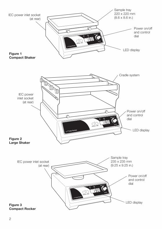
Figure 1Compact Shaker
Figure 2Large Shaker
Sample tray 220 x 220 mm(8.6 x 8.6 in.)
LED display
Cradle system
LED display
IEC power inlet socket
(at rear)
IEC power inlet socket(at rear)
Power on/off and control dial
Power on/off and control dial
Figure 3Compact Rocker
Sample tray 235 x 235 mm(9.25 x 9.25 in.)
LED display
IEC power inlet socket(at rear)
Power on/off and control dial
3
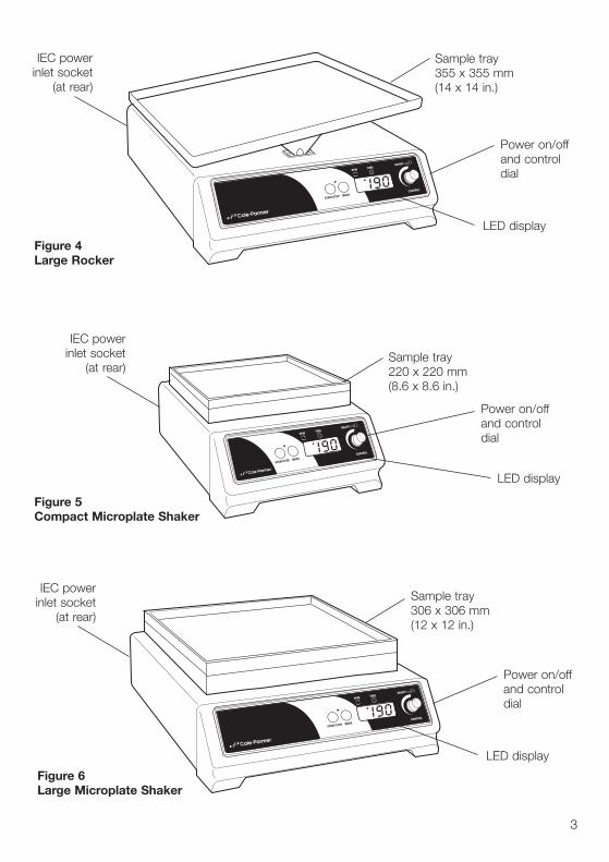
Sample tray 355 x 355 mm(14 x 14 in.)
LED display
Figure 4Large Rocker
IEC power inlet socket
(at rear)
Power on/off and control dial
Sample tray 220 x 220 mm (8.6 x 8.6 in.)
LED display
Figure 5Compact Microplate Shaker
IEC power inlet socket
(at rear)
Power on/off and control dial
Sample tray 306 x 306 mm (12 x 12 in.)
LED display
Figure 6Large Microplate Shaker
IEC power inlet socket
(at rear)
Power on/off and control dial

Shakers & Rockers
IntroductionThank you for purchasing this Cole-Parmer product. To get the best performance from the equipment, and for your own safety, please read these instructions carefully before use. Before discarding the packaging check that all parts are present and correct.
This equipment is designed to operate under the following conditions:
❖ For indoor use only❖ Use in a well ventilated area❖ Ambient temperature range +5°C to +40°C (+41°F to +104°F)❖ Altitude to 2000 m (6500ft)❖ Relative humidity not exceeding 80%❖ Power supply fluctuations not exceeding 10% of nominal❖ Overvoltage category II IEC60364-4-443❖ Pollution degree 2 IEC664❖ Use with a minimum distance all round of 200 mm (8 in.) from walls or other items
If the equipment is not used in the manner described in this manual and with accessories other than those recommended by the manufacturer, the protection provided may be impaired.
Electrical Installation
THIS EQUIPMENT MUST BE GROUNDED
Before connection please ensure that the line supply corresponds to that shown on the rating plate located on the base of the unit.
Power requirements:120 V Models 230 V Models
51700-08 50 W 51700-13 50 W 51700-15 50 W 51700-17 50 W 51700-19 50 W 51700-21 50 W 51700-23 50 W 51900-51 50 W 51900-57 50 W
The 120 V Models are provided with a NEMA 5-15 plug. The 230 V Models are provided with a UK 3-pin and a “Schuko” 2-pin plug.
Should the cable not be suitable for connecting to the power supply, replace the plug with a suitable alternative.
THIS OPERATION SHOULD ONLY BE UNDERTAKEN BY A QUALIFIED ELECTRICIAN.
NOTE: Refer to the equipment rating plate to ensure that the plug and fusing are suitable for thevoltage and wattage stated.
4
51700-10 50 W 51700-14 50 W 51700-16 50 W 51700-18 50 W 51700-20 50 W 51700-22 50 W 51700-24 50 W51900-53 50 W 51900-55 50 W
5
The wires in the power cable (120 V) are colored as follows:BLACK - HOT/LIVEWHITE - NEUTRALGREEN - EARTH
The wires in the power cable (230 V) are colored as follows:BROWN - HOT/LIVEBLUE - NEUTRALGREEN/YELLOW - EARTH
IF IN DOUBT CONSULT A QUALIFIED ELECTRICIAN
Should the power cable need replacing, a cable of 1 mm2 of harmonized code H05W-F connectedto an IEC320 plug should be used.
The appropriate power cable should be connected BEFORE connection to the power supply.
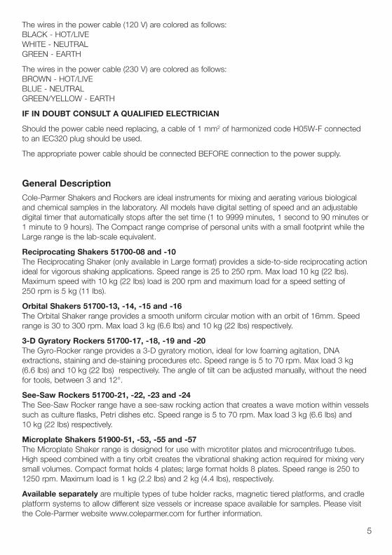
General DescriptionCole-Parmer Shakers and Rockers are ideal instruments for mixing and aerating various biological and chemical samples in the laboratory. All models have digital setting of speed and an adjustable digital timer that automatically stops after the set time (1 to 9999 minutes, 1 second to 90 minutes or 1 minute to 9 hours). The Compact range comprise of personal units with a small footprint while the Large range is the lab-scale equivalent.
Reciprocating Shakers 51700-08 and -10 The Reciprocating Shaker (only available in Large format) provides a side-to-side reciprocating action ideal for vigorous shaking applications. Speed range is 25 to 250 rpm. Max load 10 kg (22 lbs). Maximum speed with 10 kg (22 lbs) load is 200 rpm and maximum load for a speed setting of 250 rpm is 5 kg (11 lbs).
Orbital Shakers 51700-13, -14, -15 and -16The Orbital Shaker range provides a smooth uniform circular motion with an orbit of 16mm. Speed range is 30 to 300 rpm. Max load 3 kg (6.6 lbs) and 10 kg (22 lbs) respectively.
3-D Gyratory Rockers 51700-17, -18, -19 and -20The Gyro-Rocker range provides a 3-D gyratory motion, ideal for low foaming agitation, DNA extractions, staining and de-staining procedures etc. Speed range is 5 to 70 rpm. Max load 3 kg (6.6 lbs) and 10 kg (22 lbs) respectively. The angle of tilt can be adjusted manually, without the need for tools, between 3 and 12°.
See-Saw Rockers 51700-21, -22, -23 and -24The See-Saw Rocker range have a see-saw rocking action that creates a wave motion within vessels such as culture flasks, Petri dishes etc. Speed range is 5 to 70 rpm. Max load 3 kg (6.6 lbs) and 10 kg (22 lbs) respectively.
Microplate Shakers 51900-51, -53, -55 and -57The Microplate Shaker range is designed for use with microtiter plates and microcentrifuge tubes. High speed combined with a tiny orbit creates the vibrational shaking action required for mixing very small volumes. Compact format holds 4 plates; large format holds 8 plates. Speed range is 250 to 1250 rpm. Maximum load is 1 kg (2.2 lbs) and 2 kg (4.4 lbs), respectively.
Available separately are multiple types of tube holder racks, magnetic tiered platforms, and cradle platform systems to allow different size vessels or increase space available for samples. Please visit the Cole-Parmer website www.coleparmer.com for further information.
Operation
Position the rocker/shaker on a firm level surface but DO NOT connect to the power supply yet.
Please refer to the installation instructions for any accessories before applying power and ensure there is sufficient room for the unit to operate.
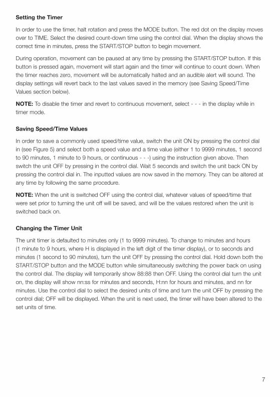
Setting the Speed
Connect the unit to the power supply and load the sample tray, ensuring it is evenly balanced.
Switch the unit ON by pressing the control dial in (see Figure 5). The LED display will show present set speed (red dot in the display shows RPM is selected). This can be adjusted by turning the controldial. Once the correct speed is displayed, press the START/STOP button to begin movement. Movement can be halted at any time by pressing the START/STOP button again. To switch the unit OFF completely, press the control dial in.
6
Safety Advice
Users should be aware of the following safety advice:
❖ The unit should be carried using both hands with the fingers under the side edges.
❖ NEVER move or carry the unit with containers on the top or while still connected to the power
supply.
❖ DO NOT mix combustible liquids or use the equipment in hazardous atmospheres.
❖ In case of power interruption, the unit will NOT continue to operate on removal of fault.
❖ In case of mechanical interruption (i.e, motor stall), the unit will continue to operate on removal of fault.
❖ Mechanical energy can lead to breakage of glass vessels. Use with care.
❖ DO NOT position the unit such that it is difficult to disconnect it from the power by removing the
power cable from the socket at the back.
❖ NEVER stop the movement by hand and ALWAYS ensure the sample plate is evenly balanced.
❖ ALWAYS ensure is sufficient free space around the unit so that it does not come in contact with
anything else during use.
❖ Additional mechanical hazard for the Reciprocating Shaker; cradle platform should be fully assembled before operation.
Figure 5
7
Setting the Timer
In order to use the timer, halt rotation and press the MODE button. The red dot on the display moves over to TIME. Select the desired count-down time using the control dial. When the display shows the correct time in minutes, press the START/STOP button to begin movement.
During operation, movement can be paused at any time by pressing the START/STOP button. If this button is pressed again, movement will start again and the timer will continue to count down. When the timer reaches zero, movement will be automatically halted and an audible alert will sound. The display settings will revert back to the last values saved in the memory (see Saving Speed/Time Values section below).
NOTE: To disable the timer and revert to continuous movement, select - - - in the display while in timer mode.
Saving Speed/Time Values
In order to save a commonly used speed/time value, switch the unit ON by pressing the control dial in (see Figure 5) and select both a speed value and a time value (either 1 to 9999 minutes, 1 second to 90 minutes, 1 minute to 9 hours, or continuous - - -) using the instruction given above. Then switch the unit OFF by pressing in the control dial. Wait 5 seconds and switch the unit back ON by pressing the control dial in. The inputted values are now saved in the memory. They can be altered at any time by following the same procedure.
NOTE: When the unit is switched OFF using the control dial, whatever values of speed/time that were set prior to turning the unit off will be saved, and will be the values restored when the unit is switched back on.
Changing the Timer Unit
The unit timer is defaulted to minutes only (1 to 9999 minutes). To change to minutes and hours (1 minute to 9 hours, where H is displayed in the left digit of the timer display), or to seconds and minutes (1 second to 90 minutes), turn the unit OFF by pressing the control dial. Hold down both the START/STOP button and the MODE button while simultaneously switching the power back on using the control dial. The display will temporarily show 88:88 then OFF. Using the control dial turn the unit on, the display will show nn:ss for minutes and seconds, H:nn for hours and minutes, and nn for minutes. Use the control dial to select the desired units of time and turn the unit OFF by pressing the control dial; OFF will be displayed. When the unit is next used, the timer will have been altered to the set units of time.
8
Cleaning and Care
WARNING: Ensure the unit is disconnected from the power supply before attempting maintenance or servicing.
The unit should be cleaned using a damp cloth and a mild detergent solution.
Cleaning is made easier if spillages are attended to promptly. In any case, spillages of acids andalkalies MUST be removed immediately as these chemicals can attack and damage the casework finish. Ensure that the appropriate safety precautions are observed.
Accessories
Multi-Platform SystemTiered platforms are available to increase the available space for samples.
Cradle SystemCradle platform systems are available and allow different vessel sizes to be accommodated.
Tube Holder RacksMicrocentrifuge tube holders are available to hold 1.5 mL, 0.5 mL, or 0.2 mL microtubes.
Please visit the Cole-Parmer website www.coleparmer.com for further information.
Servicing & Repair
This product range does not require any routine servicing.
Note: There are no internal user replaceable parts.
In the event of product failure it is recommended that any repair is only undertaken by suitably qualified personnel. For advice, please contact Cole-Parmer quoting the model and serial number.
Only spare parts supplied by the manufacturer or its agent should be used. Fitting of non-approved parts may affect the performance of the safety features of the instrument.
If in doubt, please contact Cole-Parmer.
Warranty
Cole-Parmer warrants this equipment to be free from defects in material and workmanship, whenused under normal laboratory conditions, for a period of three (3) years. In the event of a justifiedclaim, Cole-Parmer will replace any defective component or replace the unit free of charge.
This warranty does NOT apply if:
❖ Any repair has been made or attempted other than by the manufacturer or its agent.
❖ Any minor coating chips or scratches occur during normal use (i.e., wear and tear).
❖ Damage is caused by fire, accident, misuse, neglect, incorrect adjustment or repair, damage caused by installation, adaptation, modification or fitting of non-approved parts.
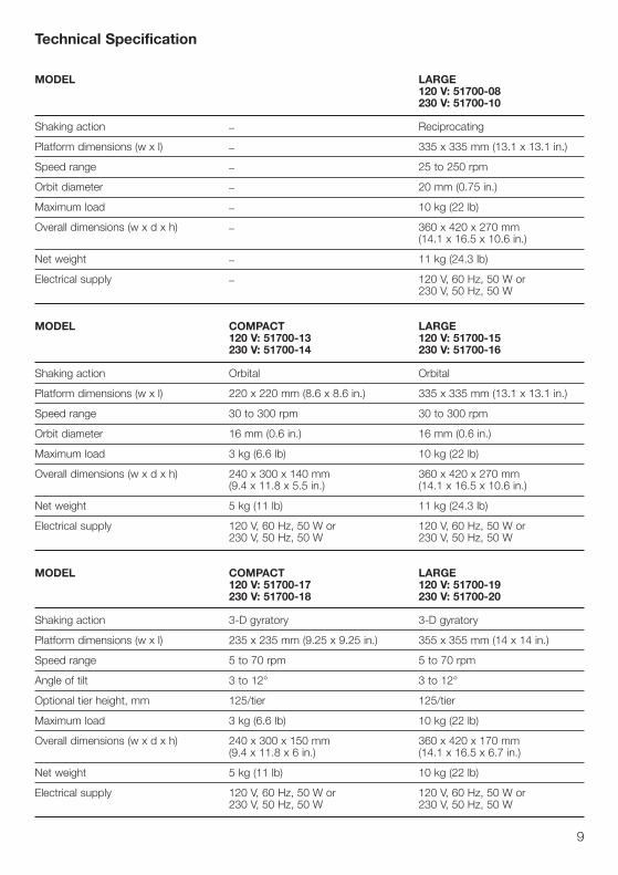
Technical Specification
MODEL LARGE 120 V: 51700-08 230 V: 51700-10 Shaking action _ Reciprocating
Platform dimensions (w x l) _ 335 x 335 mm (13.1 x 13.1 in.)
Speed range _ 25 to 250 rpm
Orbit diameter _ 20 mm (0.75 in.)
Maximum load _ 10 kg (22 lb)
Overall dimensions (w x d x h) _ 360 x 420 x 270 mm (14.1 x 16.5 x 10.6 in.)
Net weight _ 11 kg (24.3 lb)
Electrical supply _ 120 V, 60 Hz, 50 W or 230 V, 50 Hz, 50 W
MODEL COMPACT LARGE 120 V: 51700-13 120 V: 51700-15 230 V: 51700-14 230 V: 51700-16
Shaking action Orbital Orbital
Platform dimensions (w x l) 220 x 220 mm (8.6 x 8.6 in.) 335 x 335 mm (13.1 x 13.1 in.)
Speed range 30 to 300 rpm 30 to 300 rpm
Orbit diameter 16 mm (0.6 in.) 16 mm (0.6 in.)
Maximum load 3 kg (6.6 lb) 10 kg (22 lb)
Overall dimensions (w x d x h) 240 x 300 x 140 mm 360 x 420 x 270 mm (9.4 x 11.8 x 5.5 in.) (14.1 x 16.5 x 10.6 in.)
Net weight 5 kg (11 lb) 11 kg (24.3 lb)
Electrical supply 120 V, 60 Hz, 50 W or 120 V, 60 Hz, 50 W or 230 V, 50 Hz, 50 W 230 V, 50 Hz, 50 W
MODEL COMPACT LARGE 120 V: 51700-17 120 V: 51700-19 230 V: 51700-18 230 V: 51700-20
Shaking action 3-D gyratory 3-D gyratory
Platform dimensions (w x l) 235 x 235 mm (9.25 x 9.25 in.) 355 x 355 mm (14 x 14 in.)
Speed range 5 to 70 rpm 5 to 70 rpm
Angle of tilt 3 to 12° 3 to 12°
Optional tier height, mm 125/tier 125/tier
Maximum load 3 kg (6.6 lb) 10 kg (22 lb)
Overall dimensions (w x d x h) 240 x 300 x 150 mm 360 x 420 x 170 mm (9.4 x 11.8 x 6 in.) (14.1 x 16.5 x 6.7 in.)
Net weight 5 kg (11 lb) 10 kg (22 lb)
Electrical supply 120 V, 60 Hz, 50 W or 120 V, 60 Hz, 50 W or 230 V, 50 Hz, 50 W 230 V, 50 Hz, 50 W
9
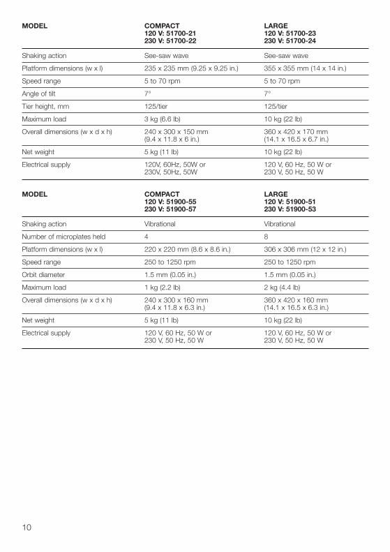
MODEL COMPACT LARGE 120 V: 51700-21 120 V: 51700-23 230 V: 51700-22 230 V: 51700-24
Shaking action See-saw wave See-saw wave
Platform dimensions (w x l) 235 x 235 mm (9.25 x 9.25 in.) 355 x 355 mm (14 x 14 in.)
Speed range 5 to 70 rpm 5 to 70 rpm
Angle of tilt 7° 7°
Tier height, mm 125/tier 125/tier
Maximum load 3 kg (6.6 lb) 10 kg (22 lb)
Overall dimensions (w x d x h) 240 x 300 x 150 mm 360 x 420 x 170 mm (9.4 x 11.8 x 6 in.) (14.1 x 16.5 x 6.7 in.)
Net weight 5 kg (11 lb) 10 kg (22 lb)
Electrical supply 120V, 60Hz, 50W or 120 V, 60 Hz, 50 W or 230V, 50Hz, 50W 230 V, 50 Hz, 50 W
MODEL COMPACT LARGE 120 V: 51900-55 120 V: 51900-51 230 V: 51900-57 230 V: 51900-53
Shaking action Vibrational Vibrational
Number of microplates held 4 8
Platform dimensions (w x l) 220 x 220 mm (8.6 x 8.6 in.) 306 x 306 mm (12 x 12 in.)
Speed range 250 to 1250 rpm 250 to 1250 rpm
Orbit diameter 1.5 mm (0.05 in.) 1.5 mm (0.05 in.)
Maximum load 1 kg (2.2 lb) 2 kg (4.4 lb)
Overall dimensions (w x d x h) 240 x 300 x 160 mm 360 x 420 x 160 mm (9.4 x 11.8 x 6.3 in.) (14.1 x 16.5 x 6.3 in.)
Net weight 5 kg (11 lb) 10 kg (22 lb)
Electrical supply 120 V, 60 Hz, 50 W or 120 V, 60 Hz, 50 W or 230 V, 50 Hz, 50 W 230 V, 50 Hz, 50 W
10
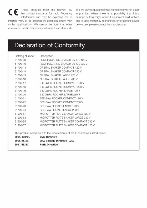
Catalog Number: Description: 51700-08 RECIPROCATING SHAKER LARGE 120 V 51700-10 RECIPROCATING SHAKER LARGE 230 V 51700-13 ORBITAL SHAKER COMPACT 120 V 51700-14 ORBITAL SHAKER COMPACT 230 V 51700-15 ORBITAL SHAKER LARGE 120 V 51700-16 ORBITAL SHAKER LARGE 230 V 51700-17 3-D GYRO-ROCKER COMPACT 120 V 51700-18 3-D GYRO-ROCKER COMPACT 230 V 51700-19 3-D GYRO-ROCKER LARGE 120 V 51700-20 3-D GYRO-ROCKER LARGE 230 V 51700-21 SEE-SAW ROCKER COMPACT 120 V 51700-22 SEE-SAW ROCKER COMPACT 230 V 51700-23 SEE-SAW ROCKER LARGE 120 V 51700-24 SEE-SAW ROCKER LARGE 230 V 51900-51 MICROTITER PLATE SHAKER LARGE 120 V 51900-53 MICROTITER PLATE SHAKER LARGE 230 V 51900-55 MICROTITER PLATE SHAKER COMPACT 230 V 51900-57 MICROTITER PLATE SHAKER COMPACT 120 V
This product complies with the requirements of the EU Directives listed below: 2004/108/EC EMC Directive
2006/95/EC Low Voltage Directive (LVD)
2011/65/EC RoHs Directive
Declaration of Conformity
These products meet the relevant EC harmonized standards for radio frequency interference and may be expected not to
interfere with, or be affected by, other equipment with similar qualifications. We cannot be sure that other equipment used in their vicinity will meet these standards
and we cannot guarantee that interference will not occur in practice. Where there is a possibility that injury, damage or loss might occur if equipment malfunctions due to radio frequency interference, or for general advice before use, please contact the manufacturer.

For technical, sales or servicing information, contact:
Cole-Parmer625 East Bunker CourtVernon Hills, IL 60061-1844Toll-Free: 800-323-4340Phone: 847-549-7600Fax: 847-247-2929www.coleparmer.com