shallow foundation
TRANSCRIPT

Shallow Foundations

Shallow Foundations Bearing Capacity
• The problems of soil mechanics can be divided into two principal groups -stability problems and elasticity problems
- Karl Terzaghi, 1943
Karl Terzaghi (1883-1963)
• Father of modern soil mechanics
• Born in Prague, Czechoslovakia
• Wrote “Erdbaumechanick” in 1925
• Taught at MIT (1925-1929)
• Taught at Harvard (1938 and after)
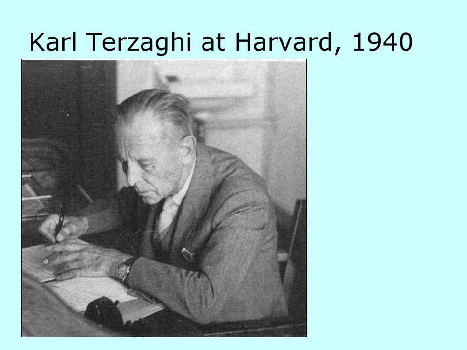
Karl Terzaghi at Harvard, 1940

Foundation: The lowest part of a structure is generally referred to as
foundation. Its function is to transfer load of the superstructure to the soil
on which it is resting.
Foundation Soil or Bed: The soil or bed to which loads are transmitted
from the base of the structure.
Footing: The portion of the foundation of the structure, which transmits
loads directly to the foundation soil.
Bearing Capacity: The load carrying capacity of foundation soil or rock
which enables it to bear and transmit loads from a structure.
Definitions
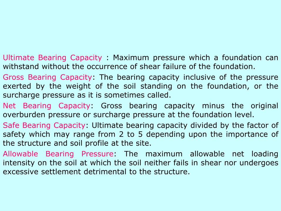
Ultimate Bearing Capacity : Maximum pressure which a foundation canwithstand without the occurrence of shear failure of the foundation.
Gross Bearing Capacity: The bearing capacity inclusive of the pressureexerted by the weight of the soil standing on the foundation, or thesurcharge pressure as it is sometimes called.
Net Bearing Capacity: Gross bearing capacity minus the originaloverburden pressure or surcharge pressure at the foundation level.
Safe Bearing Capacity: Ultimate bearing capacity divided by the factor ofsafety which may range from 2 to 5 depending upon the importance ofthe structure and soil profile at the site.
Allowable Bearing Pressure: The maximum allowable net loadingintensity on the soil at which the soil neither fails in shear nor undergoesexcessive settlement detrimental to the structure.

Factors Affecting Bearing Capacity
1. Nature of soil and its physical and engineering properties.
2. Nature of the foundation and other details such as the size, shape, depth below the ground surface and rigidity of the structure.
3. Total and differential settlements that the structure can withstand without functional failure.
4. Location of the ground water table relative to the level of the foundation
5. Initial stresses if any

Bearing Capacity Failure

Transcosna Grain ElevatorCanada (Oct. 18, 1913)
West side of foundation sank 24-ft

Stability ProblemBearing Capacity Failure
• Bearing Capacity Analysis
• How do we estimate the maximum bearing pressure that the soil can withstand before failure occurs?

Bearing Capacity Failures
Types/Modes of Failure
general shear failure
local shear failure
punching shear failure

General Shear Failure
1. Sudden or catastrophic failure
2. Well defined failure surface
3. Bulging on the ground surface
adjacent to foundation
4. Common failure mode in dense
sand
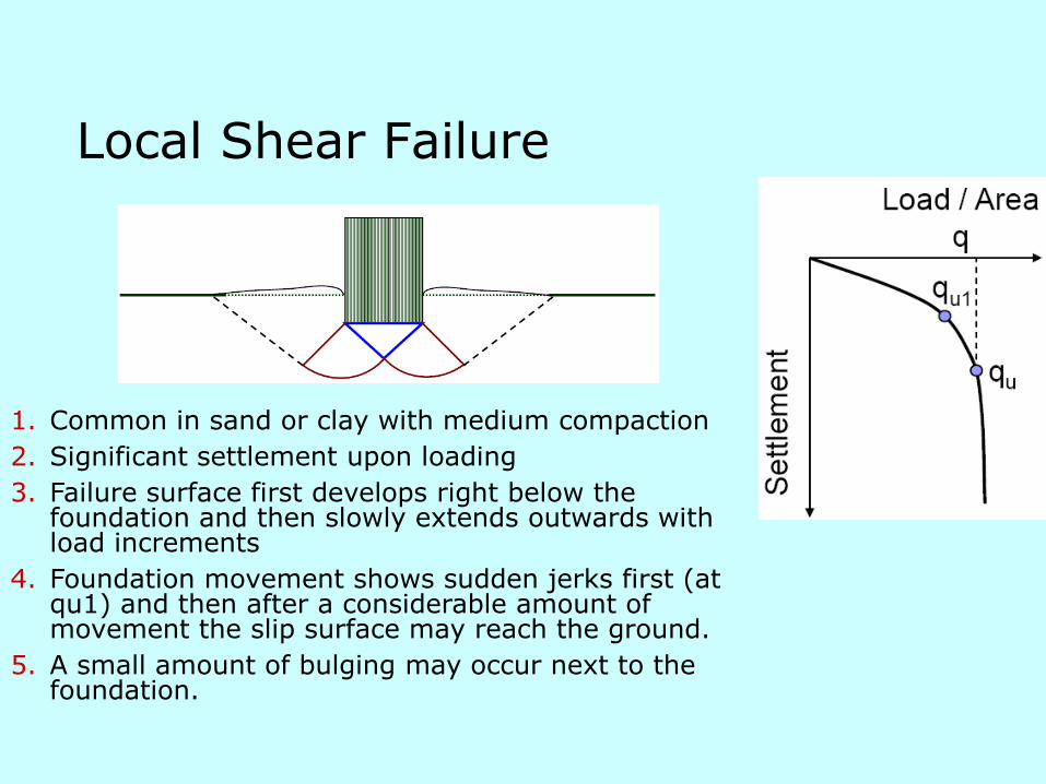
Local Shear Failure
1. Common in sand or clay with medium compaction
2. Significant settlement upon loading
3. Failure surface first develops right below the foundation and then slowly extends outwards with load increments
4. Foundation movement shows sudden jerks first (at qu1) and then after a considerable amount of movement the slip surface may reach the ground.
5. A small amount of bulging may occur next to the foundation.

Punching Shear Failure
1. Common in fairly loose sand or soft clay
2. Failure surface does not extends beyond the zone
right beneath the foundation
3. Extensive settlement with a wedge shaped soil
zone in elastic equilibrium beneath the
foundation. Vertical shear occurs around the
edges of foundation.
4. After reaching failure load-settlement curve
continues at some slope and mostly linearly.

Model Tests by Vesic (1973)

General Guidelines
Footings in clays - general shear
Footings in Dense sands ( > 67%)
-general shear
Footings in Loose to Medium dense
sands (30%< < 67%) - Local Shear
Footings in Very Loose Sand ( < 30%)-punching shear
rD
rD
rD

Methods of Determining Bearing Capacity
1. Bearing capacity tables in various building codes.
2. Analytical methods
3. Model tests
4. Plate bearing tests
5. Penetration tests
6. Laboratory tests

Bearing Capacity from Building Codes

Analytical Methods
1. Theory of Elasticity (Schleicher’s method)
2. Classical earth pressure thery – Rankine’smethod, Pauker’s method and Bell’smethod.
3. Theory of Plasticity- Fellenius’ method,Prandtl’s method, Terzaghi’s method,Meyerhof’s method, Skempton’s method,Hasen’s method and Balla’s method.

Terzaghi Bearing Capacity Formulas
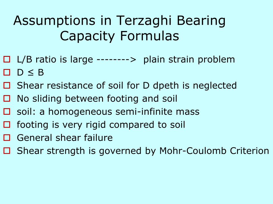
Assumptions in Terzaghi Bearing Capacity Formulas
L/B ratio is large --------> plain strain problem
D ≤ B
Shear resistance of soil for D dpeth is neglected
No sliding between footing and soil
soil: a homogeneous semi-infinite mass
footing is very rigid compared to soil
General shear failure
Shear strength is governed by Mohr-Coulomb Criterion
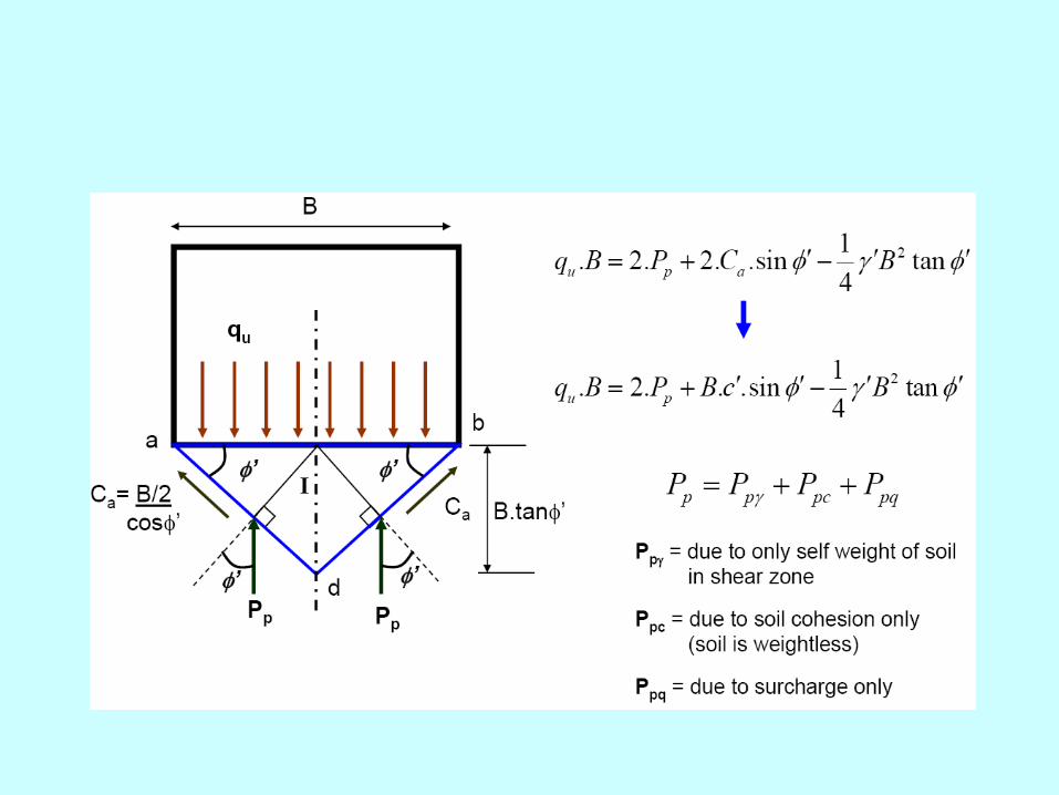


Terzaghi Bearing Capacity Formulas
BNNqcNq qcu '5.0.
For Square foundations:
For Continuous foundations:
BNNqcNq qcu '4.0.3.1
For Circular foundations:
BNNqcNq qcu '3.0.3.1

Bearing Capacity Factors
Angle of shearing resistance (f) (Deg.)
Terzaghi’s bearing capacity factors
Nc Nq N
0 5.7 1 0
5 7.3 1.6 1.5
10 9.6 2.7 1.2
15 12.9 4.4 2.5
20 17.7 7.4 5
25 25.1 12.7 9.7
30 37.2 22.5 19.7
35 57.8 41.4 42.4
40 95.7 81.3 100.4
45 172.3 173.3 297.5
50 347.5 415.1 1153
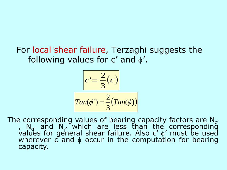
For local shear failure, Terzaghi suggests the following values for c’ and f’.
cc3
2'
)(3
2)'( ff TanTan
The corresponding values of bearing capacity factors are Nc’, Nq’ and N’ which are less than the correspondingvalues for general shear failure. Also c’ f’ must be usedwherever c and f occur in the computation for bearingcapacity.
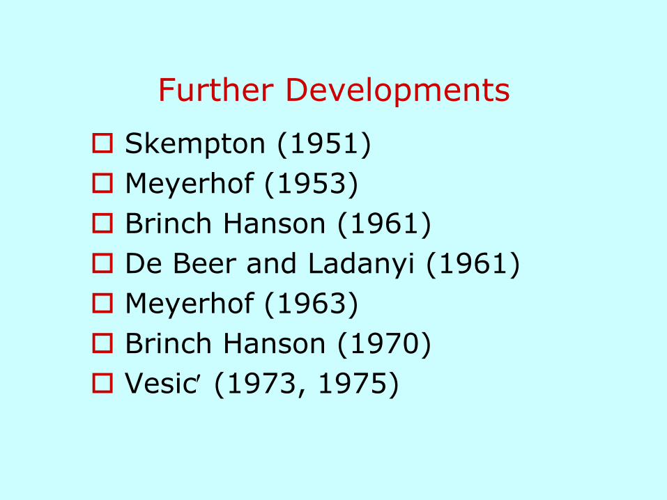
Further Developments
Skempton (1951)
Meyerhof (1953)
Brinch Hanson (1961)
De Beer and Ladanyi (1961)
Meyerhof (1963)
Brinch Hanson (1970)
Vesic (1973, 1975)
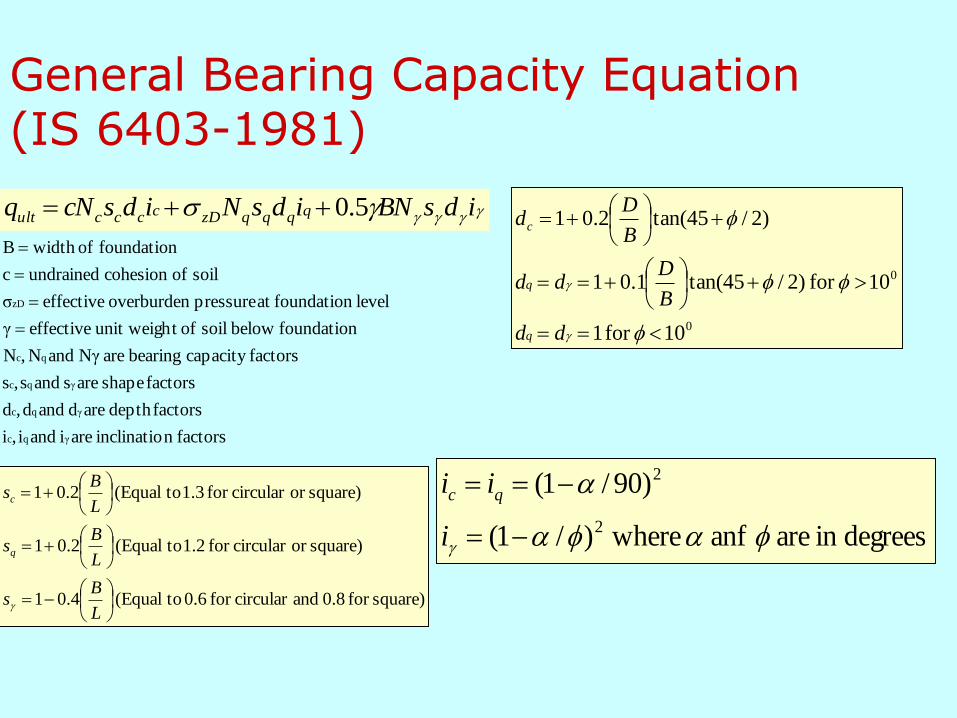
General Bearing Capacity Equation(IS 6403-1981)
idsBNidsNidscNq qqqqzDccccult 5.0
factorsn inclinatio arei andi,i
factorsdepth ared andd,d
factors shape ares ands,s
factorscapacity bearing are Nγ andN,N
foundation below soil oft unit weigh effectiveγ
level foundationat pressure overburden effectiveσ
soil ofcohesion undrainedc
foundation ofwidth B
γ qc
γ qc
γ qc
qc
zD
square)for 0.8 andcircular for 0.6 to(Equal 4.01
square)or circular for 1.2 to(Equal 2.01
square)or circular for 1.3 to(Equal 2.01
L
Bs
L
Bs
L
Bs
q
c
0
0
10 for 1
10 for )2/45tan(1.01
)2/45tan(2.01
f
ff
f
dd
B
Ddd
B
Dd
q
q
c
degreesin are anf where)/1(
)90/1(
2
2
ff
i
ii qc
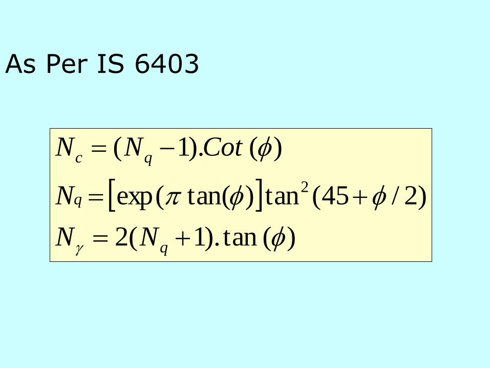
As Per IS 6403
)( tan).1(2
)2/45(tan)tan(exp(
)( ).1(
2
f
ff
f
q
q
qc
NN
N
CotNN

Groundwater Table Effect

Groundwater Table Effect; Case I
1. Modify ′zD
2. Calculate ′ as follows:
wb
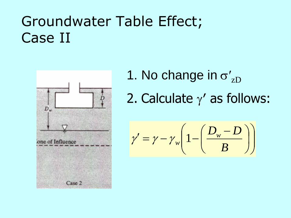
Groundwater Table Effect; Case II
1. No change in ′zD
2. Calculate ′ as follows:
B
DDww 1

Groundwater Table Effect; Case III
1. No change in ′zD
2. No change in ′

Allowable Bearing Capacity
F
qq ult
a
….. Allowable Bearing Capacity
F …. Factor of safety
aq

Factor of Safety
Depends on:
Type of soil
Level of Uncertainty in Soil Strength
Importance of structure and consequences of failure
Likelihood of design load occurrence

Minimum Factor of Safety

Selection of Soil Strength Parameters
Use Saturated Strength Parameters
Use Undrained Strength in clays (cu)
Use Drained Strength in sands,
Intermediate soils that where partially drained conditions exist, engineers have varying opinions; Undrained Strength can be used but it will be conservative!
f and c

Accuracy of Bearing Capacity Analysis
In Clays …..Within 10% of true value (Bishop and Bjerrum, 1960)
Smaller footings in Sands…. Bearing capacity calculated were too conservative –but conservatism did not affect construction cost much
Large footings in Sands … Bearing capacity estimates were reasonable but design was controlled by settlement
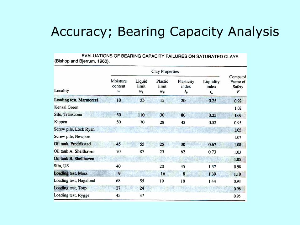
Accuracy; Bearing Capacity Analysis
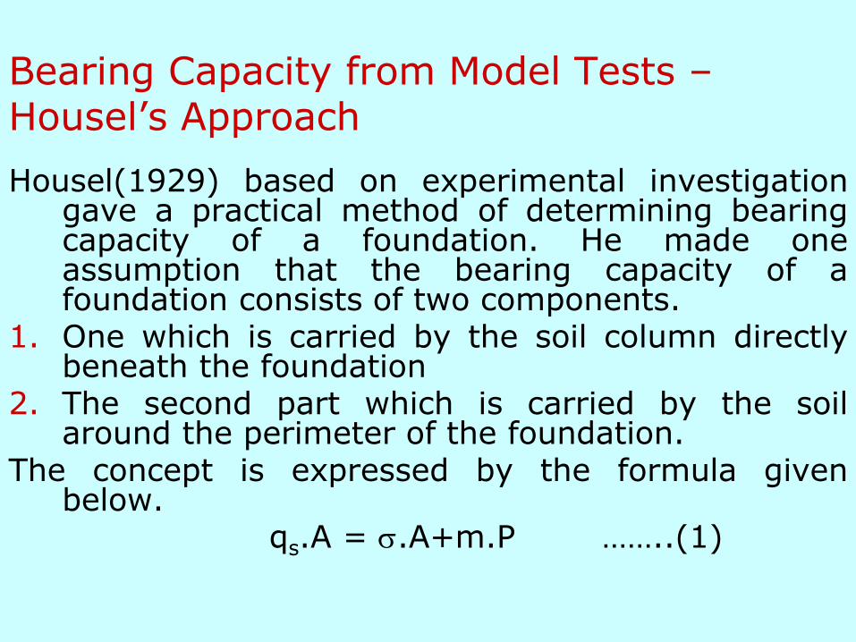
Bearing Capacity from Model Tests –Housel’s Approach
Housel(1929) based on experimental investigationgave a practical method of determining bearingcapacity of a foundation. He made oneassumption that the bearing capacity of afoundation consists of two components.
1. One which is carried by the soil column directlybeneath the foundation
2. The second part which is carried by the soilaround the perimeter of the foundation.
The concept is expressed by the formula givenbelow.
qs.A = .A+m.P ……..(1)

Where
qs = bearing capacity of the foundation in kPa
= contact pressure developed under the bearing area of the foundation (an experimental constant)
m = perimeter shear (an experimental constant)
A = bearing area of foundation
P = perimeter of the foundation

A
Pmqs .
xmqs .Where x represents perimeter-area ratio. Housel assumes that
and m are constant for different loading tests on the same soilfor a specific settlement which would be tolerated by thefoundation. Hence he suggested that and m be determined byconducting small-scale model tests by loading two or more testsplates or model footings which have different areas and differentperimeters and measuring the total load required to produce thespecified allowable settlement in each case at the proposed levelof the foundation. This gives two or more simultaneousequations from which and m may be determined. Then thebearing capacity of the proposed foundation may be computedby substituting for x of the proposed foundation in the aboveequation (3).
…………(2)
…………(3)

Bearing Capacity from Plate Load Tests
1. Test Plates size 300 to 750mm.
2. Test pit should be atleastfive times as wide as thetest plate and the bottom ofthe test plate shouldcorrespond to the proposedfoundation level.
3. Bigger size plates arepreferred in cohesive soils.
4. If ground water isencountered, it should beremoved by pumping.

5. A seating load of 7 kN.m2 isapplied and released beforeactual loading iscommenced.
6. The load is applied inincrements and thesettlements are recorded for1, 4, 10, 20 60min and for24 hours. Once settlementceases then next loadincrement is applied andagain the above procedure isrepeated.
7. Finally a load settlementcurve is plotted.
Dense sand, gravel and stiff clay
Loose sand or soft clay
Many c-f soils
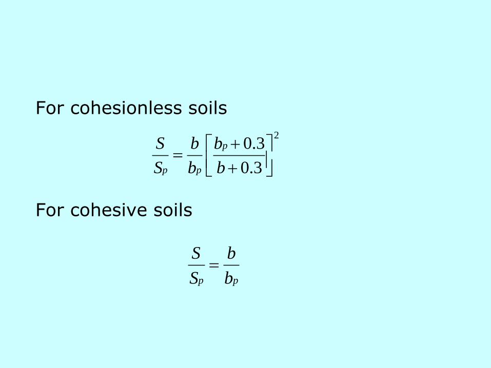
For cohesionless soils
For cohesive soils
2
3.0
3.0
b
b
b
b
S
S p
pp
pp b
b
S
S
Limitation of PLT
1. Since the size of the plate and size of the foundationare different, the results of a plate load tests do notreflect the bearing capacity of the foundation.
2. Consolidation settlements in clays which may takeyears cannot be predicted.
3. Results can not be used for strip footing as tests areconducted using square or circular plate.
4. The load test results reflect the characteristics of thesoil located only within a depth of about twice thewidth of the plate.

Bearing Capacity from Penetration Tests
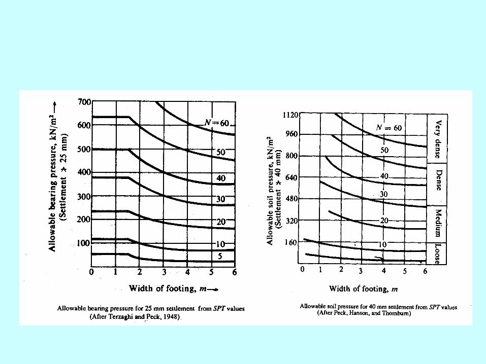
The standard penetration test results are in the formof “Penetration Number, N” which indicates thenumber of blows required to cause 300 mmpenetration of a split spoon sampler into the soilunder test by means of a 65 kg hammer fallingthrough 750 mm. This value has been correlatedto Terzaghi’s bearing capacity factors, densityindex and angle of shearing resistance (f).Terzaghi and Peck have also prepared charts forallowable bearing pressure, based on a standardallowable settlement for footings of known widthson sand whose N values are known.

Bearing Capacity from Laboratory Tests
The bearing capacity of a cohesive soil can beevaluated from the unconfined compressionstrength (qu).
)2/45tan(2 01 f cqu
When f = 00, for a purely cohesive soil
uu cq 2
This is applicable when D = 0. The ultimate bearingcapacity may be divided by a suitable factor of safety(say 3) to get safe bearing capacity.

Bearing Capacity for Sands
)1.(.... NqDNbq ultnet
Where a
0.5 for continuous footing
0.4 for square footing
0.3 for circular footing
Thus the net ultimate bearing capacity depends upon
1. The unit weight of soil
2. Angle of shearing resistance besides the size and depth of the footing
Peck, Hanson and Thornburn (1953) have developed charts forevaluating f and Terzaghi’s bearing capacity factors from theSPT value ‘N”.

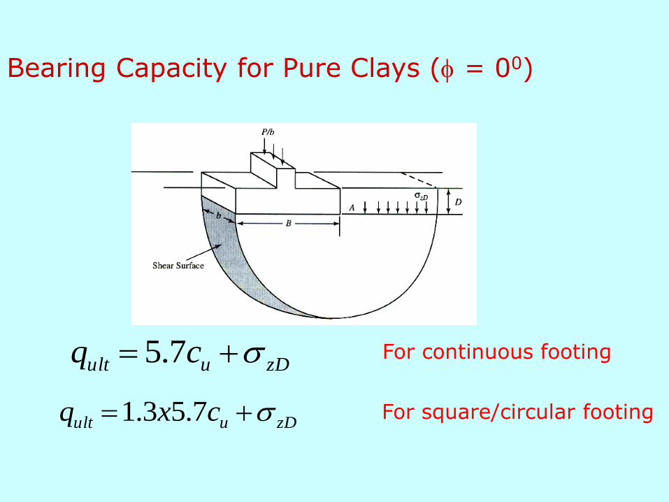
Bearing Capacity for Pure Clays (f = 00)
zDuult cq 7.5
zDuult cxq 7.53.1
For continuous footing
For square/circular footing

Shallow Foundations - Settlement
Sources of Settlement
Design Requirements
Induced Stresses Beneath Shallow Foundations
Settlement Analysis Based on Laboratory Tests
Settlement in Stratified Soils
Differential Settlement
Rate of Settlement
Accuracy of Settlement Predictions
Sources of Settlement
1. Elastic compression of the foundation and the underlying soil giving rise to what is known as immediate settlement.
2. Plastic compression of the underlying soil giving rise to consolidation settlement of fine grained soils.
3. Ground water lowering
4. Vibration due to pile driving
5. Seasonal swelling and shrinkage of expansive soils
6. Surface erosion, creep
7. Miscellaneous sources such as adjacent excavation, mining subsidence and under ground erosion.
The settlement from the first two sources can be predicted with fair degree of confidence.
Design Requirements
Total Settlement ()
Differential Settlement(D)
a
DaD
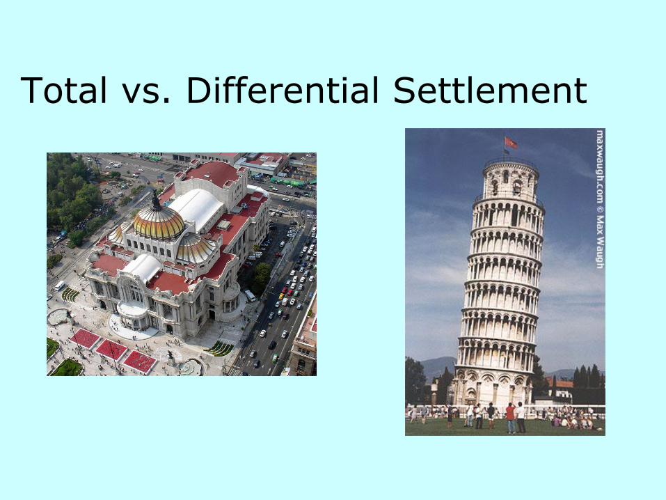
Total vs. Differential Settlement