shawn nick - quteprints.qut.edu.au/74751/1/shawn_nick_thesis.pdf · shawn nick principal...
TRANSCRIPT

Shawn Nick
Principal Supervisor: Dr. Ghavameddin Nourbakhsh
Associate Supervisor: Prof. Arindam Ghosh
Submitted in fulfilment for the degree of completion of
Master of Engineering (Research)
School of Electrical Engineering and Computer Science (EECS)
Science and Engineering Faculty (SEF)
Queensland University of Technology (QUT)
Brisbane, Australia
2014
An investigation approach to test Protection Intelligent
Electronic Devices (IEDs) in IEC 61850 based Substation
Automation Systems (SAS) at Station level


i An investigation approach to test Protection Intelligent Electronic Devices (IEDs) in
IEC 61850 based Substation Automation Systems (SAS) at Station level
Keywords
IEC 61850, GOOSE, Testing, Substation Automation, Protection Relay, Test equipment, non-
conventional relay testing, Station level, SAS, Virtual Trip

ii
An investigation approach to test Protection Intelligent Electronic Devices (IEDs) in
IEC 61850 based Substation Automation Systems (SAS) at Station level
Abstract
IEC 61850 standard “communication Networks and Systems in Substations” offers a
worldwide recognized technique for interoperability between Intelligent Electronic Devices
(IEDs) from different manufacturers. It eliminates most of control and protection wirings by
its capability for fast data sharing over the Ethernet network. In order to make various IEDs to
communicate with each other and manage a large number of devices in a digital substation, a
new communication model was required. This model was built up in IEC 61850 standard. This
standard has introduced lots of new features and challenges to the test and commissioning
electrical substation as well as the protection design. Testing protection relays in such
environment requires a fresh knowledge of the new technologies and non-conventional testing
equipment.
All non-conventional test sets and protection relays have dedicated software for managing
IEC61850 elements. So for instance a secondary injection test set knows what messages should
be captured on the network to be used as virtual contacts and the protection relay knows what
messages should be used as virtual binary input. However, there has been always a missing
element in regards to testing a protection relay in an IEC 61850 environment as the end user
doesn’t know what is happening in the background of test set and relay programs. This can be
very dangerous in an energized substation as any wrong digital message may cause a wrong
circuit breaker operation! or virtual binaries of another relay are read instead of the right ones.
This can be due to a software maloperation or end user failure. In a conventional substation,
hardwires are checked according to the substation schematics but using IEC 61850 programs
hide everything in the background. An investigation has been conducted in this work to reveal
the background of information exchange between the test equipment and protection relays and
show the relation between the entities that the end user sees in the software programs and the
standard document.
This research also develops a new approach to trace virtual signals over the IEC61850 station
bus by testing a protection function of a native IEC61850 protection relay, using a non-
conventional test set by analyzing the contents of GOOSE messages (Generic Object Oriented
Substation Event) that are used as virtual contacts in very low level.
iii An investigation approach to test Protection Intelligent Electronic Devices (IEDs) in
IEC 61850 based Substation Automation Systems (SAS) at Station level
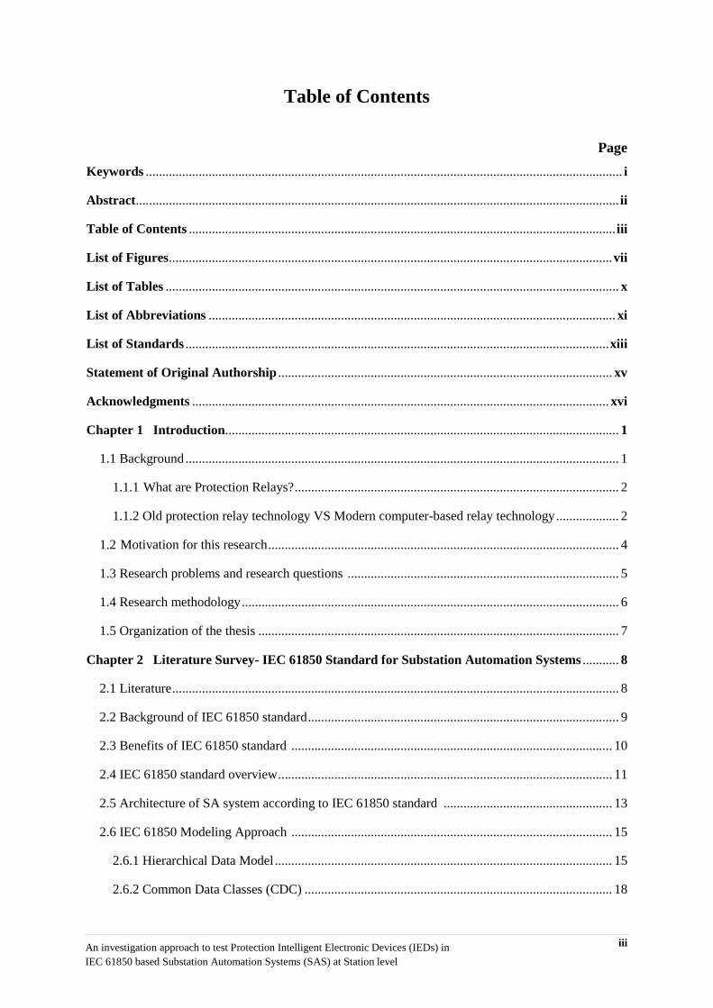
Table of Contents
Page
Keywords ................................................................................................................................................ i
Abstract .................................................................................................................................................. ii
Table of Contents ................................................................................................................................. iii
List of Figures ...................................................................................................................................... vii
List of Tables ......................................................................................................................................... x
List of Abbreviations ........................................................................................................................... xi
List of Standards ................................................................................................................................ xiii
Statement of Original Authorship ..................................................................................................... xv
Acknowledgments .............................................................................................................................. xvi
Chapter 1 Introduction ....................................................................................................................... 1
1.1 Background ................................................................................................................................... 1
1.1.1 What are Protection Relays? .................................................................................................. 2
1.1.2 Old protection relay technology VS Modern computer-based relay technology ................... 2
1.2 Motivation for this research .......................................................................................................... 4
1.3 Research problems and research questions .................................................................................. 5
1.4 Research methodology .................................................................................................................. 6
1.5 Organization of the thesis ............................................................................................................. 7
Chapter 2 Literature Survey- IEC 61850 Standard for Substation Automation Systems ........... 8
2.1 Literature ....................................................................................................................................... 8
2.2 Background of IEC 61850 standard .............................................................................................. 9
2.3 Benefits of IEC 61850 standard ................................................................................................. 10
2.4 IEC 61850 standard overview ..................................................................................................... 11
2.5 Architecture of SA system according to IEC 61850 standard ................................................... 13
2.6 IEC 61850 Modeling Approach ................................................................................................. 15
2.6.1 Hierarchical Data Model ...................................................................................................... 15
2.6.2 Common Data Classes (CDC) ............................................................................................. 18

iv
An investigation approach to test Protection Intelligent Electronic Devices (IEDs) in
IEC 61850 based Substation Automation Systems (SAS) at Station level
2.6.3 Standardizing object names ................................................................................................. 20
2.7 Communication in IEC 61850 .................................................................................................... 22
2.7.1 Communication stack and mapping to real protocols .......................................................... 22
2.7.2 Client-Server and Peer-Peer communications ..................................................................... 23
2.7.2.1 GOOSE and MMS ....................................................................................................... 23
2.7.2.2 Sampled Values ........................................................................................................... 26
2.8 Data Sets and Control Blocks ..................................................................................................... 26
2.8.1 Data Sets .............................................................................................................................. 26
2.8.2 Report Control Blocks ......................................................................................................... 27
2.8.3 GOOSE Control Blocks ....................................................................................................... 28
2.9 Substation Configuration description Language (SCL) .............................................................. 29
2.9.1 SCL General Concept .......................................................................................................... 29
2.9.2 Engineering concept of SCL in IEC 61850-6 ...................................................................... 30
Chapter 3 Analysis ........................................................................................................................... 32
3.1 Protection Relay .......................................................................................................................... 32
3.1.1 Background .......................................................................................................................... 32
3.1.2 Distance Protection in EuroProt+ DTVA series .................................................................. 33
3.1.3 Distance Protection Introduction ......................................................................................... 34
3.1.4 Relay Hardware.................................................................................................................... 36
3.1.4.1 CPU and Communication module ............................................................................... 36
3.1.4.2 Human Machine Interface (HMI) module ................................................................... 37
3.1.4.3 Power Supply Unit ....................................................................................................... 38
3.1.4.4 Analog Input cards (Current and Voltage modules) .................................................... 38
3.1.4.5 Digital Input card (Binary Input module) .................................................................... 38
3.1.4.6 Digital Output card (Signaling and tripping modules) ................................................. 38
3.1.5 IED Configuration Toll (EuroCap) ...................................................................................... 39
3.1.5.1 Hardware Configuration tool (Rack Designer) ............................................................ 39
3.1.5.2 Function Blocks tool .................................................................................................... 41
3.1.5.3 Online setting tool (Web server) .................................................................................. 41
v An investigation approach to test Protection Intelligent Electronic Devices (IEDs) in
IEC 61850 based Substation Automation Systems (SAS) at Station level
3.1.5.4 Matrix ........................................................................................................................... 42
3.1.5.5 Offline setting tool (EuroSet) ....................................................................................... 43
3.1.5.6 LCD Configuration tool (LCD Editor) ........................................................................ 43
3.1.5.7 Graphical Logic Editor ................................................................................................ 44
3.1.5.8 IEC 61850 Configuration tool...................................................................................... 45
3.1.5.8.1 Data Model in IEC 61850 configuration tool .............................................. 46
3.2 Non-conventional Testing Equipment ........................................................................................ 47
3.2.1 Background .......................................................................................................................... 47
3.2.2 Hardware specification ........................................................................................................ 49
3.2.3 Software tool ........................................................................................................................ 49
3.2.4 Distance Protection testing program .................................................................................... 49
3.2.5 IEC 61850 Interface in DRTS66 .......................................................................................... 50
3.3 Network Analyzer software ........................................................................................................ 51
3.3.1 Background .......................................................................................................................... 52
3.3.2 GOOSE filter ....................................................................................................................... 52
Chapter 4 Laboratory work- Testing a Distance Protection Relay in IEC 61850-8-1
environment ........................................................................................................................................ 53
4.1 Test structure ............................................................................................................................... 53
4.2 Software tools configuration ....................................................................................................... 56
4.2.1 DTVA Protection Relay configuration ................................................................................ 56
4.2.1.1 Distance protection parameter setting .......................................................................... 57
4.2.1.2 Hardware configuration ............................................................................................... 58
4.2.1.3 IEC 61850 configuration .............................................................................................. 59
4.2.1.3.1 Introducing GGIO Logical Node ................................................................. 60
4.2.1.4 logic Design ................................................................................................................. 62
4.2.1.5 Final Configuration for Distance protection and GOOSE publisher FBs .................... 63
4.2.1.5.1 Configuration in Logic Editor Program ...................................................... 63
4.2.1.5.2 Configuration of “Communication Configurator” tool ................................ 64
4.2.2 Test Equipment setup ........................................................................................................... 66

vi
An investigation approach to test Protection Intelligent Electronic Devices (IEDs) in
IEC 61850 based Substation Automation Systems (SAS) at Station level
4.2.2.1 TDMS parameter setting .............................................................................................. 66
4.2.2.2 Hardwiring for Analog injection and Networking ....................................................... 68
4.3 Test execution ............................................................................................................................. 69
4.3.1 Testing functionality of GGIO FB ....................................................................................... 69
4.3.1.1 Creating Virtual Pushbuttons ....................................................................................... 70
4.3.1.1.1 Creating a Matrix column for GOOSE publisher ....................................... 71
4.3.1.1.2 Creating a Matrix row as an “Always True” signal .................................... 71
4.3.1.1.3 Creating a new GCB for Virtual Pushbuttons ............................................. 73
4.3.1.1.4 Activating GGIO inputs for matrix column and BI .................................... 74
4.3.1.2 Using virtual push buttons for testing GGIO function ................................................. 75
4.3.2 Testing Distance protection function using virtual trips ................................................... 80
4.3.2.1 Virtual contact configuration in TDMS software ....................................................... 82
4.3.2.2 Verify the R/X characteristic ....................................................................................... 85
4.3.2.3 Automatic time zone test Z-t ........................................................................................ 87
4.3.2.4 Wireshark analysis ....................................................................................................... 89
Chapter 5 Conclusion ...................................................................................................................... 91
5.1 Summary ..................................................................................................................................... 91
5.2 Future prospects .......................................................................................................................... 92
Appendix A Test Results ................................................................................................................... 95
References ......................................................................................................................................... 101

vii An investigation approach to test Protection Intelligent Electronic Devices (IEDs) in
IEC 61850 based Substation Automation Systems (SAS) at Station level
List of Figures
Figure 2.1: Process Level and Sample Measured Value Concept........................................................ 14
Figure 2.2: Typical IEC61850 Substation Architecture ....................................................................... 15
Figure 2.3: Explore layout for data model for logical node LPHD ...................................................... 16
Figure 2.4: Object modeling for an IED with more than one LD ........................................................ 17
Figure 2.5: Hierarchical Data Modeling ............................................................................................... 17
Figure 2.6: Explorer layout of Measurement unit logical node showing its DOs and DAs .................. 18
Figure 2.7: Structure of hierarchical object model in IEC 61850 ......................................................... 21
Figure 2.8: Examples of object naming for highlighted DOs in figure 1.7 according to IEC 61850-8-1
.............................................................................................................................................................. 21
Figure 2.9: Explorer layout for object naming of Current and Voltage measurement functions .......... 22
Figure 2.10: Overview of IEC 61850 Protocol Stack structure (Page 19 of IEC 61850-8-1 standard
document (5)) ........................................................................................................................................ 23
Figure 2.11: IEC 61850 Communication Structure ............................................................................. 24
Figure 2.12: Example of a Data Set (Start) .......................................................................................... 27
Figure 2.13: RCB for a Measurement Data Set ................................................................................... 28
Figure 2.14: Explorer layout of a GoCB (GCB) consists of DAs for binary status of a function block
.............................................................................................................................................................. 29
Figure 2.15: The use of Substation Configuration Language (SCL) ................................................... 31
Figure 3.1: EuroProt+/DTVA Distance protection relay (31) ............................................................. 33
Figure 3.2: Distance protection function in EuroProt+ multifunction Relay ........................................ 34
Figure 3.3: Distance protection Polygon-shaped characteristics (32) .................................................. 35
Figure 3.4: Protection zone grading ..................................................................................................... 36
Figure 3.5: CPU and communication board (35) ................................................................................. 37
Figure 3.6: EuroProt+ HMI module (34) .............................................................................................. 37
Figure 3.7: Hardware and software structure of EuroProt+ family (37) .............................................. 39
Figure 3.8: Modifying factory configuration in rack designer tool (half size version) ........................ 40
Figure 3.9: Module selection window showing the choice of the binary output modules .................... 40
Figure 3.10: Distance protection function in FBs list .......................................................................... 41
Figure 3.11: Web interface tool for online parameter setting and remote control ................................ 42
Figure 3.12: Web interface tool for Matrix configuration ................................................................... 43
Figure 3.13: Configurable user screen on the front panel LCD ........................................................... 44
Figure 3.14: Graphic equation for protection functions in Logic editor tool ....................................... 45
Figure 3.15: Data model objects in explorer view in IEC 61850 Configuration tool .......................... 46

viii
An investigation approach to test Protection Intelligent Electronic Devices (IEDs) in
IEC 61850 based Substation Automation Systems (SAS) at Station level
Figure 3.16: Creating a new GCB and DS from a DA of a LN ........................................................... 47
Figure 3.17: DRTS 66 test equipment ................................................................................................. 48
Figure 3.18: Front panel interface for testing IEDs without using PC ................................................. 48
Figure 3.19: “Distance 21” program in TDMS software ..................................................................... 50
Figure 3.20: Applying GOOSE filter in Wireshark Network Analyzer ............................................... 52
Figure 4.1: Relay connection to IEC61850 Station Bus ...................................................................... 55
Figure 4.2: Test bed for testing station level functions of an IEC 61850-compatible relay ................. 55
Figure 4.3: Software tools used for the test bed ................................................................................... 56
Figure 4.4: Web interface of EuroProt+ is used to set distance parameters ......................................... 57
Figure 4.5: Module arrangement of the Relay in “Rack Designer” program in EuroCap software...... 59
Figure 4.6: Communication Configurator tool for IEC 61850 configuration ....................................... 60
Figure 4.7: Data Objects in GGIO Logical Node ................................................................................. 60
Figure 4.8: Go8 GOOSE Publisher FB in Logic Editor that represents GGIO LN .............................. 61
Figure 4.9: Status information of the GGIO LN in the SCL Browser ................................................. 61
Figure 4.10: Trip signals of Distance FB in Logic Editor tool ............................................................. 63
Figure 4.11: 3 phase Trip output from Distance FB is assigned to first input of GGIO GOOSE
Publisher FB ......................................................................................................................................... 64
Figure 4.12: State values (stVal) of the first input is used to make a new Data Set ............................. 65
Figure 4.13: Creating a new GCB for Virtual Trip using the existing Dataset .................................... 65
Figure 4.14: ISA TDMS Test software ................................................................................................. 66
Figure 4.15: Using EuroSet offline parameter setting tool to Generate RIO file .................................. 67
Figure 4.16: Relay R/X characteristics in “Distance21” program transferred through RIO file .......... 68
Figure 4.17: Front panel of DRTS66 test set ........................................................................................ 68
Figure 4.18: A new Matrix column is created in EuroCap “Software configuration” to represent first
input of GGIO FB ................................................................................................................................. 71
Figure 4.19: Creating an “Always True status in “Logic Editor” tool .................................................. 72
Figure 4.20: A new Matrix row is created in EuroCap “software configuration” to represent the
“Always true” signal ............................................................................................................................. 72
Figure 4.21: State values (stVal) of the first two inputs of GGIO LN are used to make a new Data Set
.............................................................................................................................................................. 73
Figure 4.22: The new GCB is created using the existing Dataset ......................................................... 74
Figure 4.23: Assigning inputs to GGIO FB in “Logic Editor” tool ...................................................... 75
Figure 4.24: Selecting the Network Interface in Wireshark ................................................................. 75
Figure 4.25: Different types of Network packets are captured by Wireshark ....................................... 76
Figure 4.26: Applying GOOSE filter expression in Wireshark ............................................................ 76
Figure 4.27: Only the GOOSE packets are shown when the GOOSE filter is applied ......................... 77
Figure 4.28: Boolean Values of the GGIO inputs are “0 or False” in the received GOOSE message 77
ix An investigation approach to test Protection Intelligent Electronic Devices (IEDs) in
IEC 61850 based Substation Automation Systems (SAS) at Station level
Figure 4.29: Matrix tool in Relay web interface is used to change the status of first input GGIO FB . 78
Figure 4.30: StVal of the first input of GGIO has been changed from “0” to “1 or True” ................... 78
Figure 4.31: The default status of “BIn0603” that has been assigned to second GGIO Input disabled
.............................................................................................................................................................. 79
Figure 4.32: “BIn0603” is now enabled in the simulation mode .......................................................... 79
Figure 4.33: “StVal” of the second input of GGIO has now been changed from “0” to “1 or True” ... 80
Figure 4.34: General function tests of Distance21 program and 4 zones relay characteristic .............. 81
Figure 4.35: Using IEC 61850-8-1 interface instead of conventional BIs for relay trip contacts ......... 82
Figure 4.36: Setting BIs for distance testing (conventional and non-conventional digital inputs) ....... 83
Figure 3.37: “Goose Explorer” program is ready to sniff the Station Bus for GOOSE messages ........ 83
Figure 4.38: List of captured GOOSE messages on the Station Bus in “Goose Explorer”
program .................................................................................................................................... 84
Figure 4.39: Using the Boolean value of the selected GCB as virtual contact ..................................... 85
Figure 4.40: R/X characteristic test to verify 4 zones of the EuroProt+ relay ...................................... 86
Figure 4.41: Test results of “Verify the R/X characteristic” ................................................................. 86
Figure 4.42: Setting up the time zone test in “Distance21” program .................................................... 87
Figure 4.43: Test result of time zone test in R/X diagram ....................................................... 88
Figure 4.44: Test result of time zone test in Z/t diagram ......................................................... 88
Figure 4.45: Boolean Value of the GGIO input 1 is “0 or False” in the received GOOSE
message for “Virtual Trip” DS ................................................................................................ 89
Figure 4.46: Boolean Value of the GGIO input 1 is “1 or True” in the received GOOSE message for
“Virtual Trip” DS ....................................................................................................................... 90
x
An investigation approach to test Protection Intelligent Electronic Devices (IEDs) in
IEC 61850 based Substation Automation Systems (SAS) at Station level
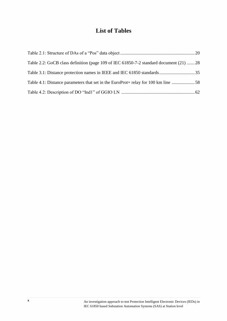
List of Tables
Table 2.1: Structure of DAs of a “Pos” data object ................................................................. 20
Table 2.2: GoCB class definition (page 109 of IEC 61850-7-2 standard document (21) ....... 28
Table 3.1: Distance protection names in IEEE and IEC 61850 standards ............................... 35
Table 4.1: Distance parameters that set in the EuroProt+ relay for 100 km line .................... 58
Table 4.2: Description of DO “Ind1” of GGIO LN ................................................................ 62

xi An investigation approach to test Protection Intelligent Electronic Devices (IEDs) in
IEC 61850 based Substation Automation Systems (SAS) at Station level
List of Abbreviations
IED Intelligent Electronic Device
GW Gateway
HMI Human Machine Interface
UCA Utility Communications Architecture
EPRI Electric Power Research Institute
SA Substation Automation
SAS Substation Automation System
A/D Analog to digital
MU Merging Unit
CB Circuit breaker
CT Current transformer
VT Voltage Transformer
ICU Intelligent Control Unit
SCL Substation Configuration Language
SCADA Supervisory Control and Data Acquisition
CDC Common Data Classes
ACSI Abstract Communication Services Interface
DS Disconnector Switch
I/O Input output
DFR Digital Fault Recording
PQ Power Quality
SMV Sampled Measured Value
LN Logical Node
LD Logical Device
PSU Power Supply Unit
PD Physical Device
DO Data Object
CB Control Block
DS Data Set
Comm Communication
DA Data Attribute
DAType Data Attribute Type
FC Functional Constraint

xii
An investigation approach to test Protection Intelligent Electronic Devices (IEDs) in
IEC 61850 based Substation Automation Systems (SAS) at Station level
DPC Double Point Control
SV Sampled value
MMS Manufacturing Message Specification
TCP/IP Transmission Control Protocol/Internet Protocol
GSE Generic Substation Event
GSSE Generic Substation State Event
GOOSE Generic Object Oriented Substation Event
OSI Open System Interconnection
LAN Local Area network
XML eXtensible Markup Language
ICD IED Capability Description
SSD System Specification Description
SCD Substation Configuration Description
CID Configured IED Description
IID Instantiated IED Description
SED System Exchange Description
SAV Sampled Analog Values
RCB Report Control Block
BRCB Buffered Report Control Block
URCB Unbuffered Report Control Block
GoCB GOOSE Control Block
GCB GOOSE Control Block
EOB Optical Ethernet Over Board
PPM Pulse Per Minute
FB Function Block
GUI Graphical User Interface
API Application Programming Interface
VLAN Virtual LAN
GGIO Generic Process Input Output
BO Binary Output
BI Binary Input
TWS Travelling Wave fault location System
ASN Abstract Syntax Notation
RBD Reliability Block Diagram

xiii An investigation approach to test Protection Intelligent Electronic Devices (IEDs) in
IEC 61850 based Substation Automation Systems (SAS) at Station level
List of Standards
Standard Title
IEC 61850 Communication networks and systems for power utility
automation
IEC TR 61850-1 Part 1: Introduction and overview
IEC 61850-3 Part 3: General requirements
IEC 61850-4 Part 4: System and project management
IEC 61850-5 Part 5: Communication requirements for functions and device
models
IEC 61850-6 Ed.2
Part 6: Configuration description language for communication in
electrical substations related to IEDs
IEC 61850-7-2 Part 7-2: Basic information and communication structure—
Abstract communication service interface (ACSI)
IEC 61850-7-3
Part 7-3: Basic communication structure for substations and
feeder equipment – Common data classes
IEC 61850-7-4 Part 7-4: Basic communication structure—Compatible logical
node classes and data object classes
IEC 61850-8-1
Part 8-1: Specific communication service mapping (SCSM)—
Mappings to MMS (ISO 9506-1 and ISO 9506-2) and to
ISO/IEC 8802-3
IEC 61850-9-2 Part 9-2: Specific communication service mapping (SCSM)—
Sampled values over ISO/IEC 8802-3
xiv
An investigation approach to test Protection Intelligent Electronic Devices (IEDs) in
IEC 61850 based Substation Automation Systems (SAS) at Station level
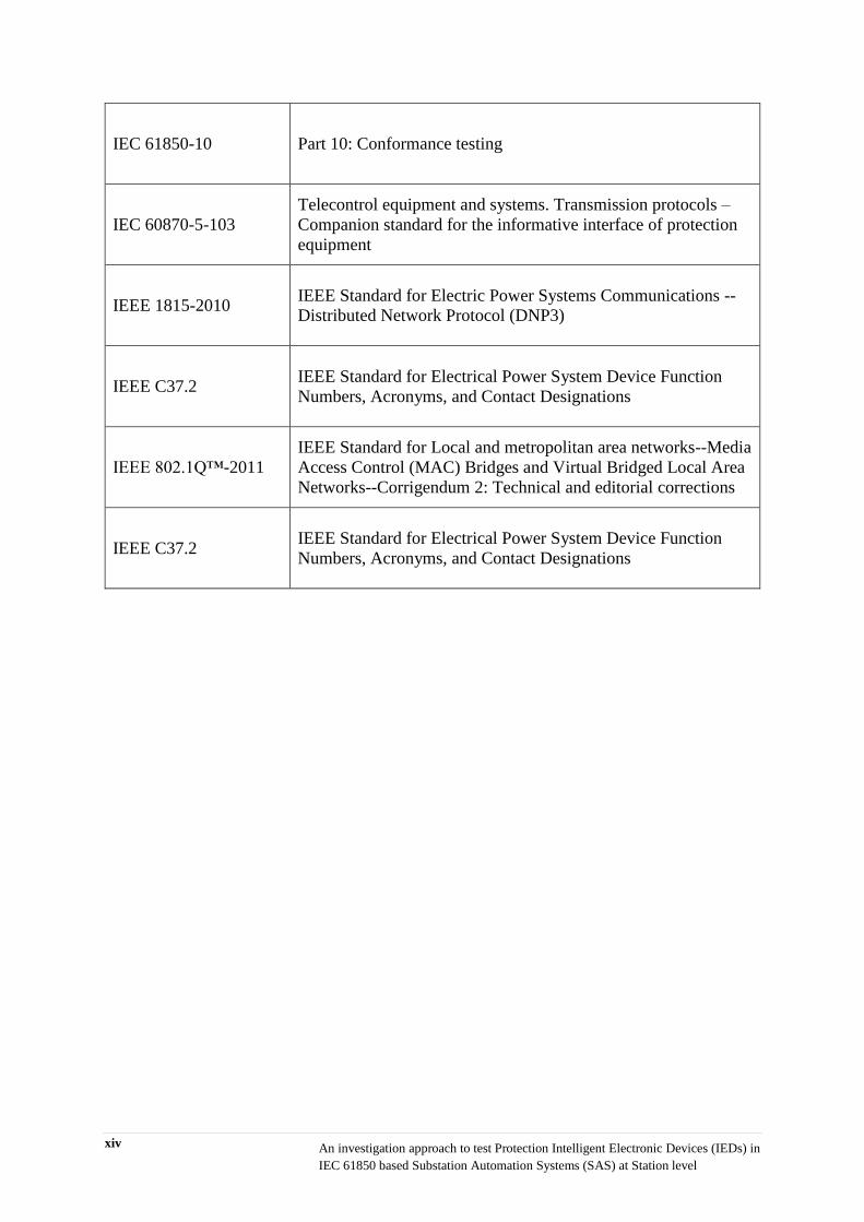
IEC 61850-10 Part 10: Conformance testing
IEC 60870-5-103
Telecontrol equipment and systems. Transmission protocols –
Companion standard for the informative interface of protection
equipment
IEEE 1815-2010 IEEE Standard for Electric Power Systems Communications --
Distributed Network Protocol (DNP3)
IEEE C37.2 IEEE Standard for Electrical Power System Device Function
Numbers, Acronyms, and Contact Designations
IEEE 802.1Q™-2011
IEEE Standard for Local and metropolitan area networks--Media
Access Control (MAC) Bridges and Virtual Bridged Local Area
Networks--Corrigendum 2: Technical and editorial corrections
IEEE C37.2 IEEE Standard for Electrical Power System Device Function
Numbers, Acronyms, and Contact Designations
xv An investigation approach to test Protection Intelligent Electronic Devices (IEDs) in
IEC 61850 based Substation Automation Systems (SAS) at Station level
Statement of Original Authorship
The work contained in this thesis has not been submitted previously to meet requirement of an
award at this or any other higher education institution. To the best of my knowledge and belief,
the thesis contains no material previously published or written by another person except where
due reference has been made.
Shawn Nick
Signature
Date: 4 August 2014
QUT Verified Signature

xvi
An investigation approach to test Protection Intelligent Electronic Devices (IEDs) in
IEC 61850 based Substation Automation Systems (SAS) at Station level
Acknowledgments
I would like to express my gratitude and appreciation to my Principal Supervisor, Dr.
Ghavameddin Nourbakhsh, and Associate Supervisor, Prof. Arindam Ghosh, for assisting me
to build an academic understanding and for their comments, recommendations, suggestions,
and support.
My heartfelt gratitude goes to Insulect Australia for their helps and support and allowing me to
use Insulect testing facilities in Brisbane branch. I address a very special thanks to my
Engineering manager, Melt Booysen for his encouragement and constant support.
Last but not the least, I would like to thank my parents, Homa and Ramez, my brothers,
Homayoun and Afshin and my sister, Marjan for their unconditional support they provided me
through my entire life. Finally, a very special thanks to my wife and best friend, Parisa, without
whose love and encouragement I would not have finished this thesis.

Chapter 1: Introduction 1
Chapter 1: Introduction
This chapter provides an introduction of IEC 61850 standard and communication technologies
for electrical substations. Following from this is a background of protection relays and a
comparison between old and new technologies used in protection devices. Finally, the
motivation for undertaking this research and detail research methodology are discussed.
1.1. Background
IEC 61850 standard “Communication Networks and Systems in Substations” is a new
worldwide recognized approach for communication in substations. Before IEC 61850 was
introduced in early 2000, utilities were looking for a solution for communication between
modern protection and control devices in electrical substations but they only limited to
proprietary protocols invented by different vendors. IEC 61850 came to facilitate a full
interoperability between intelligent devices from different manufacturers. This technology
accommodates a great advantage for the end-users in order to have a free choice of suppliers
for various parts of a substation. Under IEC 61850, all devices including protection, control
and monitoring devices can communicate to each other and to the software tools at upper levels
using the same services and protocols. IEC 61850 gives the opportunity to eliminate a large
number of hardwires that used to transfer the signals (commands and interlocks) between
protection and control devices in conventional substations. This also improves the functionality
of the system and reduces the cost at the same time. Moreover, the new invention in IEC 61850
technology replaces the traditional copper wires used for transferring secondary analog values
of currents and voltages from the instrument transformers (CT/VT) in the field to the protection
and monitoring devices. IEC 61850 has taken the best features of existing technologies such as
XML, Ethernet, MMS and TCP/IP, gets them working together under the new concepts
introduced in the standard like GOOSE by inventing an advanced mapping technique to work
over a super-fast network backbone (1). This, not only simplified protection design and test
and commissioning processes, but also provided a very easy solution for any user who uses
applications of a substation automation system (SAS).
The other major problem before the IEC 61850 standard was ongoing substation retrofitting
projects. During the typical 40 – 70 years asset life of the primary plant and instrument
transformers, secondary electronic equipment such as protection and control devices need to
2 Chapter 1: Introduction
be replaced at least two or three times due to their short life cycle (15 years typically). And the
new protection relays, for instance, required new complex wiring, software configuration and
protocol converters to work with an existing substation. By using IEC 61850 in the substation,
the outage period of primary system will be minimized while the refurbishing projects will be
much faster, safer and easier.
1.1.1. What are Protection Relays?
During the past years there have been lots of evolutions on power system grid such as multiple
generators, ring and parallel technologies and very long lines. Each of these evolutions has
brought a new challenge in operation and fault scenarios. Faults are occurring in all parts of
power system as an earth fault or short circuit. They might be single line to ground, three phase
short or line to line that cause a very high fault current flowing to the system. So, one of the
very first critical requirements of the power system was some protective devices to monitor the
operation of the power system equipment. Protection relays were invented at the beginning of
the history of power generation to protect the very first generators in late 1880s. In order to
protect very expensive components of a power system such as generators, transformers and
transmission feeders, relays operate to isolate the faulty section in the fastest possible time.
Any failures of protection system may result in severe equipment damage so there are normally
some backup protections for such conditions. In brief, the major responsibility of protection
relays is to isolate faulted sections of a power system by controlling the circuit breakers while
the rest of system is working normally.
1.1.2. Old protection relay technology VS Modern computer-based relay
technology
The development of protection relays over the time is categorized into four types.
- First generation – Electromechanical Relays
They were designed as uni-task protective devices that used electromechanical
hardware. They needed physical maintenance for their movable parts. Nowadays these
types of relays have been obsolete and out of production, however they are still in
operation in some old power-stations and substations (2).
Chapter 1: Introduction 3
- Second generation – Static Relays
These are solid state protective devices that sense the currents and voltages with analog
circuits and no digital conversion is done on the analog waveforms. The hardware of
these relays is made from basic semiconductors such as diode and transistors and simple
circuit components such as resistors and capacitors. This configuration results in a fixed
and simple logic for protection schemes (3). Due to the absence of the moving parts in
these relays, they consume less power, need less maintenance and have longer lifespan
compare to electromechanical relays. These relays can be still found in many power-
stations and old substations.
- Third generation – Digital Relays
As programmable microprocessors are used in these relays, they are also called
programmable relays. They enabled the protection engineers to implement any
mathematically possible characteristics and logics using the microprocessors. They
digitalize the analog current and voltage waveforms through some analog to digital
convertors (A/D) and deliver the lower burden on the secondary system of instrument
transformers (CT/VT). This generation also provided the opportunity to have multiple
protection functions in a single device. Compared to previous generation, digital relays
require less maintenance, consume less power and take less space in the protection
panels (4).
- Fourth generation – Numerical Relays
Numerical relays are using the latest computer technologies to protect the power
systems. They were introduced in early 1980 and replaced with static and
electromechanical relays in the existed installations and new constructions. Numerical
relays which are also called smart relays, use a complex computer system to develop
multi-functions protection devices in order to analyze currents and voltages of the
power system for the purpose of faults detection. Before substation automation concept
was introduced, smart relays had been used to build the secondary system of the
substations for many years. However, there were some serious limitations on
transferring data between protection devices and also to the higher substation levels
such as HMI and SCADA. All the binary signals between smart devices (i.e. interlock
applications) and analog signals from primary plant (secondary currents and voltages)
4 Chapter 1: Introduction
were transmitted by hard wires. Also, integrating multi-vendor smart devices in a
substation was difficult as each manufacturer used their proprietary communication
protocols.
In a nutshell, in the conventional protection schemes, all primary equipment such as
circuit breakers, CT/VTs and power transformers are connected to the secondary
system using the hardwires. There is normally a single function in the old relays so that
lots of equipment are used to protect, control and monitor a substation bay. On the other
hand, in the modern protection schemes, smart protection relays support more functions
in one piece of device. This is the result of the huge development of computer
technologies that are used in power system protection. So a single intelligent device can
support different functions such as protection, control, metering and fault recording.
Nowadays all protection relay manufacturers are trying to comply with different parts
of IEC 61850 standard. 61850-compatible relays replace most of the hard wires with a
few network cables and improve the system performance at the same time. By taking
advantage of the latest electronics, communication and computer technologies, 61850-
compatible devices enable the end-users to design, build and maintain substations in a
convenient way. IEC 61850 based solutions are now supporting a full interoperability
between intelligent electronic devices (IED) from different manufactures. Utilities are
now demanding IEC 61850 capabilities available in any substation related hardware or
software.
1.2. Motivation for this research
Every new technology brings new requirements as well as improving the existing systems. IEC
61850 has significantly enhanced the performance of communications in the electrical
substations but has also increased the complexity. This complexity has introduced some new
challenges to protection engineers and test and commissioning technicians. As expected, there
will be a requirement of new skills and tools to be developed. Every person who is involved
with IEC 61850 must have some basic knowledge of IEC 61850. Protection engineers should
now understand the concept of data modeling and logical nodes, and test and commissioning
technicians need to learn working with non-conventional test equipment. This is very critical
as there might be no hard wire for physical trip contacts to send the binary commands to the
circuit breakers. Instead, trip commands are sent via some virtual contacts using GOOSE

Chapter 1: Introduction 5
messages [Section 2.6.2.1]. This will raise a big concern for testing protection relays in 61850–
compatible substations, as if an inappropriate virtual contact is selected in the testing software,
a wrong circuit breaker might be operated. So it is essential that test engineers/technicians
designate the correct virtual signals in the software tools among lots of GOOSE messages
related to different IEDs. The manufacturers of non-conventional test equipment provide some
tools in the testing programs to help the end-users to find proper virtual signals based on MAC
addresses and logical device names. However, as the virtual contacts are transferred as GOOSE
Control Blocks (GCB) [Section 2.7.3], understanding the contents of control blocks (CBs) will
be a great help in the test and commissioning process. The main aim of this research is to
investigate deep into the details of the IEC 61850 elements used in station level [Section 2.4].
In order to trace GOOSE messages from the publisher IED (protection relay) to the subscriber
IED (test equipment), a third party network analyzer software needs to be used. This software
is to capture the GOOSE signals carrying the Boolean values of the virtual contacts over the
Station Bus, then the contents of the GOOSE message will be analyzed and compared with the
sender and receiver IEDs. Each IED has its own configuration software tool, however they all
follow the same rules to comply with IEC 61850 standard. The transferred information between
the relay and the test equipment is also shown in the third party software.
A full distance protection testing in IEC 61850 environment is carried out and will be explained
step by step using a non-conventional test set. This includes setting the protection parameters
in the relay software tool, transferring the setting into the test equipment and testing different
zones of a distance characteristic. The whole procedure will show how to translate the IEC
61850 entities seen in the testing and relay programs into understandable articles.
As mentioned before, this research will concentrate on the virtual signals that can be produced
from any protection functions in the relay. The reason that distance protection was chosen for
this research was that it is one of the complicated protection functions and other protection
functions such as over current and differential are tested in the same way when they come to
IEC 61850 environment. Also by testing a distance protection, full functionality of a non-
conventional test set (IEC 61850-8-1 compatible) will be shown and compared to the
conventional test sets.
1.3. Research problems and research questions
The main goal with this master research is to investigate the contents of the GOOSE messages
transferring on the Station Bus. These messages are normally used for interlocking and

6 Chapter 1: Introduction
commands that previously went through hardwires in conventional substations. Therefore, in
this research, the concentration is on testing 61850-compatible relay in IEC 61850 environment
to analyze the trip signals from the relay in a third party software.
There are some problems for performing a complete relay testing in an IEC 61850 environment.
First, a complete analysis needs to be conducted on the IEC 61850 standard documents to
provide an overview of the contents of different parts of the standard. This is very critical for
this project without that the non-conventional testing cannot be analyzed. The second issue is
finding a proper protection relay that support IEC 61850 and meet our testing specifications,
non-conventional test equipment and a third party software to act as GOOSE analyzer.
Additional requirement is that the relay, test set and network analyzer software need to be fully
studied and all user manuals and related documents have to be analyzed in detail.
1.4. Research methodology
Research methodology includes the following steps:
1- Standard analysis. An analysis of the standard is provided by an overview of all
parts of the standard. The most important concepts of IEC 61850 is explained in
details with figures and tables according to standard documentation.
2- Protection Relay. Employing a protection relay that supports IEC 61850-8-1
(station level functions) is a critical part of the project. For this purpose, EuroProt+
relay from Protecta is chosen. EuroProt+ relays are multifunction protection IEDs
that support IEC 61850 standard natively (without any protocol convertor). They
also have a standard software tool to manage the protection function settings and
IEC 61850 parameters. Several correspondences were made with the Engineering
team of Protecta in Hungry to get the relay firmware ready for the research
requirements. This includes modifying the relay software and adding some function
blocks (FB) and firmware bug fix.
3- Test equipment. A non-conventional secondary injection testing equipment shall
be provided to support station level functions (part 8-1) of the standard (5). DRTS66
test set with IEC 61850-8-1 interface from ISA manufacturer is chosen to inject the
analog values to the relay and receive the virtual trips. So the relay trip outputs are
all going through the Station Bus as virtual contacts to binary inputs of the test set
to stop analog injection without any hardwires. Again, contacts with manufacturer

Chapter 1: Introduction 7
(ISA) were initiated to report the software bugs and fix them for this research.
4- Third party network analyzer software tool. The aim of this research is to
elaborate the contents of the GOOSE signals carrying the virtual contacts from the
GOOSE publisher function block in protection relay (sender) to the GOOSE
subscriber in the test set (receiver). So a third party software tool is needed to
analyze the station level network and capture the GOOSE messages. For this
purpose, different software tools are tested and finally Wireshark application is
chosen. Wireshark is a free and open-source network analyzer that is used for
education, troubleshooting and analyzing the communication of the network. This
open-source software is the kernel of many other IEC 61850 tools.
5- Test bed. A laboratory work should be performed by using a 61850-compatible
protection relay, non-conventional 61850-compatible test equipment and a
computer with required software tools.
1.5. Organization of the thesis
This thesis is organized as follows;
Chapter one gives a brief introduction of the research. This chapter starts with the background
of Power system protection and substation automation system standard. The main research
objectives and related works are also included in this chapter.
In chapter two a comprehensive analysis has been done on the IEC 61850 standard. The history
and benefits of the standard are explained in this chapter following by elaborating the most
important concepts of the IEC 61850 standard.
Chapter three introduces the EuroProt+ as a native 61850 protection relay, the DRTS66 as a
non-conventional test equipment and Wireshark as a third party network analyzer software that
are used for different sections of this project.
Chapter four gives details of the lab works and the comprehensive analysis used to integrate
the theory into the practice.
In Chapter five conclusion and future works are discussed.

8 Chapter 2: Literature Survey- IEC 61850 Standard for Substation Automation Systems
Chapter 2: Literature Survey- IEC 61850 Standard for
Substation Automation Systems
Introduction
IEC 61850 is a collection of international standards defining how to describe the modern
devices in automated electrical substation and how to exchange the information between these
intelligent devices. Before IEC 61850 was invented, it was almost impossible to have
interoperability for multi-vendor devices as each manufacturer had their proprietary standard
for communication in automated substations (i.e. ABB LON Communication protocol (6)).
Due to the lack of a unique platform of sharing information, software tools were not able to
handle the configuration files from other manufacturers’. Also interoperation between devices
was done by hard wiring and limited to simple binary signal transfer. IEC 61850 came to
provide a full interoperability between intelligent devices from different manufacturers and
their software tools at various substation applications (7). It develops a complete
communication model to manage a large number of devices in automated substations and
eliminates most of the protection and control conventional wirings. For any IEC 61850 related
project, a fresh knowledge of different applications and services defined in the standard is
critical. In this chapter all parts of the standard will be introduced and the important concepts
will be explained in details.
2.1. Literature
The Information concerning the standard of IEC 61850 is collected directly from the documents
in the IEC standard (1), (5), (15), (18), (21), (22), (23), (27) and (30). Proudfoot D. discusses
the background of IEC 61850 standard in (8). The information about the EuroProt+ protection
relay family is collected from the Protecta webpage (31) and from the EuroProt+ relay software
and hardware manuals (32), (34), (35), (36) and (37), and from discussions with Engineering
team and technical support at Protecta company in Hungary.
Hossenlopp L., Mackiewicz R., Brunner C. and Brand K. discuss the benefits of IEC 61850
standard in (11), (12), (13) and (14). Apostolov A. in (9) and (20) and Janssen M. in (19) study
the architecture of a 61850-compatible substation including the hierarchical structure.

Chapter 2: Literature Survey- IEC 61850 Standard for Substation Automation Systems 9
Modeling approach (data model) in IEC 61850 is the most important part of the standard. This
concept is explained in part 7-2, 7-3 and 7-4 of the standard documents (21), (22) and (23).
This concept has also elaborated by Mackiewicz R. in (12), Brunner C. in (13) and Kezunovi
M. in (24).
Communication stack is a key feature in IEC 61850 standard. Part 8-1 of the standard (5)
defines the mapping technique of IEC 61850 abstract objects and services described in part 7-
2 (21) to real protocols including MMS (Manufacturing Message Specification of ISO9506),
TCP/IP (transmission control protocol/Internet protocol) and Ethernet. Brunner C. discusses
this in (13). Client-Server and Peer-Peer communications (GOOSE and MMS) is discussed by
Baigent D. in (25) and Brand K. in (26).
Transferring Sampled Analog Values (SAV) need to be considered to have a complete picture
of a 61850-compatible substation. This is explained in part 9-1 (27) and 9-2 (18) of IEC 61850
standard.
Data Sets and Control Blocks are the key elements of this research to test a protection relay in
an IEC 61850 environment. These concepts are necessary to be fully understood in order to
analyse the contents of the GOOSE packets transferring on the substation network. IEC 61850
defines Data Sets (DS) and Report Control Blocks (RCB) in part 7-2 clause 11 (21). Liang Y.
discusses this concept in (28).
Substation Configuration description Language (SCL) is an important part of the standard that
defines a formal relationship between the SAS functions and substation elements. Part 6 of IEC
61850 standard describes SCL language. Engineering concept of the SCL has been collected
from the standard documents (29).
2.2. Background of IEC 61850 standard
IEC61850 standard was published by International Electrotechnical
Commission's (IEC) Technical Committee 57 (TC57) in early 2000s to provide all required
specification for electrical substation automation. Before IEC 61850 was released, a parallel
development was taking place in the US by EPRI (Electric Power Research Institute) (8). They
were working on a project called UCA (Utility Communications Architecture) to provide
interoperability between different monitoring and control equipment in substations for real-
time utility communications across the utility enterprise. IEC was developing the IEC 61850
standard at the same time that EPRI was developing UCA standard in the US. So in 1997 it
was concluded that the members of UCA working group integrate into IEC TC 57 to complete

10 Chapter 2: Literature Survey- IEC 61850 Standard for Substation Automation Systems
a worldwide accepted standard that responds all concerns and objectives for Substation
Automation systems (SAS) (9).
The standard aimed to unify all multiple existed protocols for substation automation which had
lots of built-in proprietary protocols. These proprietary protocols had limited the end-users to
use IEDs from different vendors. IEC61850 has provided interoperability between system
components and software tools from different manufacturers and give a free choice of supplier
to the users of 61850-compliant equipment.
The standard is implemented based on well-known existed technologies such as transmission
control protocol/Internet protocol (TCP/IP), manufacturing messaging specification (MMS)
and extensible markup language (XML) (1).
The main goal of IEC 61850 standard was to promote a single protocol for SA systems to
provide a common model for different data required for a substation. It was developed to meet
the needs of different applications of protection, automation, control, recording and
measurement in the SA system. Other objectives set for the standard are:
- It should support a high level of integration between multi-vendor IEDs (plug and play
functionality)
- It should support high speed communication between IEDs to obtain the necessary
response times below four milliseconds for protective relaying (10)
- It should support flexible configuration to allow a free allocation of functions along
with different system architectures (11)
- It should have long term stability and technology independent to support future
computer and communication technologies (11)
2.3. Benefits of IEC 61850 standard
Every new technology needs to improve the existing system by increasing reliability,
decreasing costs and making the system more convenient. IEC 61850 has been showing
deliverable benefits to small and large utilities. The new requirements that IEC 61850 has
introduced to electrical substations, added some new costs for installation, configuration and
maintenance of passive and active networking equipment. However, it has saved lots of money
on the costs compared to a conventional substation. Using network messages instead of hard-
wires together with saving on design, installation, commissioning and operation can cover the
new costs. IEC 61850 capabilities and features go beyond the proprietary protocols such as
IEC 60870-5-103 (41) and DNP3 (42) (Distributed Network Protocol) (11). The benefits of

Chapter 2: Literature Survey- IEC 61850 Standard for Substation Automation Systems 11
IEC 61850 include:
- High speed data exchange between IEDs delivers better operation of the system (11)
- Peer to peer communications replaces the conventional hard-wired signal exchange
between IEDs
- Multi-vendor interoperability (12)
- XML file format for Substation Configuration Language (SCL) enables exchange of
information between engineering software tools (13)
- Object oriented and hierarchical Data Model supports logical location of data and
functions (14)
2.4. IEC 61850 standard overview
IEC 61850 standard includes of 14 documents divided into 10 different parts:
System aspects
Part 1 - Introduction and Overview
This document is an overview of the concepts and documents in the standard. It is an abstract
of other parts of the standard.
Part 2 - Glossary
This part embodies a set of specific terms and definitions from other standards in different parts
of IEC 61850 that are used in the context of Substation Automation System within the various
parts of the standard.
Part 3 - General Requirements
This part talks about the particular requirements that the standard needs to meet. Reliability,
system availability, maintainability, security and other requirements are defined in this part.
Part 4 - System and Project Management
This part describes the requirements of the system and project management process and of
special supporting tools for engineering and testing.
Configuration
Part 5 - Communication Requirements for Functions and Device Models
This part refers to the communication requirements of the functions being performed in the
substation automation system and to device models. They are detailed in several subparts of
Part 7 of the standard.
Part 6 - Substation Automation System Configuration Language (SCL)

12 Chapter 2: Literature Survey- IEC 61850 Standard for Substation Automation Systems
This part specifies a file format for describing communication related IED (Intelligent
Electronic Device) configurations and IED parameters, communication system configurations,
switchyard (function) structures and the relations between them. The purpose is to exchange
IED capability descriptions and SA system descriptions between IED engineering tools and the
system engineering tool(s) of different manufacturers in a compatible way.
Data and service models
Part 7- Basic Communication Structure for Substation and Feeder Equipment
Part 7 includes 4 subparts;
Part 7-1 Principles and Models
This subpart provides an overview of the architecture for communication and interactions
between substation devices such as protection devices, breakers, transformers, substation hosts,
etc.
Part 7-2 Abstract Communication Service Interface
This subpart applies to the ACSI communication in substations and feeder applications. The
ACSI provides the abstract interface describing communications between a client and a remote
server.
Part 7-3 Common Data Classes
This subpart specifies common attribute types and common data classes related to substation
applications.
Part 7-4 Compatible Logical Node Classes and Data Classes
This subpart specifies the information model of devices and functions related to substation
applications. It also specifies in particular the compatible logical node names and data names
for communication between Intelligent Electronic Devices, which includes the relationship
between Logical Nodes and Data.
Mapping to real communication networks
Part 8-1 Specific Communication Service Mapping (SCSM) – Mappings to MMS -
Manufacturing Message Specification-(ISO 9506-1 and ISO 9506-2) and to ISO/IEC 8802-3
This part specifies a method of exchanging time-critical and non-time-critical data through
local-area networks by mapping ACSI to MMS and ISO/IEC 8802-3 frames.
Part 9- Process Bus Mapping
This part is divided into two subparts that define two different achievements of the IEC 61850
Process Bus.
Part 9-1 Sampled values over serial unidirectional multi-drop point to point link.
Chapter 2: Literature Survey- IEC 61850 Standard for Substation Automation Systems 13
This subpart lays down the specific communication service mappings for the communication
between bay and process level in a point to point link.
Part 9-2 Specific Communication Service Mapping (SCSM) − Sampled values over ISO/IEC
8802-3
This subpart defines the Specific mapping for the transmission of sampled measured values
and model for generic object oriented system events (GOOSE).
Testing
Part 10 - Conformance Testing
This part defines the procedures for conformance testing of IEC 61850 compliant devices. (15)
2.5. Architecture of SA systems according to IEC 61850 standard
Every Substation Automation System (SAS) has a hierarchical structure and IEC 61850 defines
three typical levels for communication and application functions.
Station Level includes Human Machine Interface (HMI), station computers and Gateway
(GW). The functions related to this level are communicating over a dedicated network called
Station Bus. Some station level functions are replacing conventional hard-wires carrying binary
information between IEDs. Some other functions are acting as interface between SAS to the
station HMI and SCADA (9).
Bay Level includes Protection, control and measurement IEDs. The functions related to this
level communicate within the bay level (i.e. exchange information between IEDs), to Process
level (via Process Bus) and to station level (via Station Bus) (16).
Process Level includes primary equipment in the substation such as Current and voltage
transformers (CTs and VTs) and Circuit Breakers (CBs). The functions related to this level are
replacing analog signals from CTs and VTs with digital values. These functions communicate
over a dedicated network called ‘Process Bus’ (9).
Nonconventional instrument transformers (i.e. optical CT/VT) digitalize the analog values of
current and voltage and send them to the IEDs in the Bay level. Digitalized signals will then
go through a so called “Merging Unit” (MU) device. MUs are used to merge and synchronize
the sampled analog signals of current and voltage and transmit them to destination IEDs at Bay
level via Process Bus. Conventional CT/VT may also be connected to the MU (17). In this case
A/D convertors digitalize the analog signals at agreed sample rate according to IEC 61850-9-
2 LE (Lite Edition). IEC 61850 addresses process level requirements by the concept of Sampled
Measured Value (SMV) services in part 9-2 of the standard (18). However, the standard has

14 Chapter 2: Literature Survey- IEC 61850 Standard for Substation Automation Systems
left the exact details of using sampled values to the manufacturers. In order to provide a simple
interoperability between different vendors, UCA (Utility Communications Architecture
International Users Group) has introduced two different sampling rates for the Merging Unit
in Implementation Guideline 9-2LE (Lite Edition) (19). For basic protection and monitoring
applications, the base sample rate of 80 sample per cycle is used (4 kHz for 50 Hz power
systems). A high frequency sampling rate of 256 samples per cycle (12.8 kHz) may also be
used for high-frequency applications such as Digital Fault Recording (DFR) and Power Quality
(PQ) analysis applications (20).
Binary values such as state information of circuit breakers (CBs) and Disconnector Switches
(DS) are collected by a device called ‘Intelligent Control Unit’ (ICU) and transmitted to various
IEDs at bay level via Process bus. ICU also receives trip and close commands from the Bay
level IEDs and distributes them to HV switchgears. The ICU might be part of a MU as an
embedded module. The basic concept of Process level is shown in Figure 2.1.
Figure 2.1: Process Level and Sample Measured Value Concept

Chapter 2: Literature Survey- IEC 61850 Standard for Substation Automation Systems 15
Typical hierarchical levels in a Substation are shown in Figure 2.2.
Figure 2.2: Typical IEC61850 Substation Architecture
2.6. IEC 61850 Modeling Approach
Data model is a fundamental element in the automated substation. Parts 7-2, 7-3 and 7-4 of
IEC 61850 standard define logical architecture of a SA system and all possible functions that
operate in substation environment (13). Part 7-2 (21) defines Abstract Communication Services
Interface (ACSI), part 7-3 (22) defines Common Data Classes (CDC) and part 7-4 (23)
describes compatible logical node classes and data classes of logical system.
2.6.1. Hierarchical Data Model
Object modeling describes virtualization concept and standardizes the names of the logical
functions and their data in IEC 61850. For example the name of the “Distance Protection” is
PDIS and “Time delay Under Voltage Protection” is PTUV. Circuit breaker is also a function
and its name is XCBR. All functions that operate in a SA system are split into smallest entities
called Logical Node (LN) as concrete objects. Basically, LNs are the smallest part of the
function that exchange data in a SA system. As per examples above, PDIS and XCBR are
logical nodes and contains all related data and attributes for distance protection and circuit

16 Chapter 2: Literature Survey- IEC 61850 Standard for Substation Automation Systems
breaker correspondingly. SA related functions may be implemented individually or multiple in
any IED. IEC 61850 defines approximately 90 LNs to cover all necessary functions in the SA
systems.
For common applications such as distance protection, a group of logical nodes reside in a
Logical Device (LD). There are some necessary information about the complete IED such as
hardware health, the status of the Power Supply Unit (PSU) and communication problems that
are not available in function logical nodes and logical devices. So the function modeling is
completed by a Physical Device (PD) model that defines common properties of the IED. IEC
61850 defines the logical node LPHD (Logical node for Physical Device) that contains
common device properties for any IED such as name plate and heath report. The explorer layout
of LPHD logical node is shown in Figure 2.3.
Figure 2.3: Explorer layout for data model for logical node LPHD
The logical node LN0 (or LLN0) is a special logical node which exists in each LD and contains
common data for all LNs of a LD such as Data Sets (DS), logs, GOOSE/GSSE Control Blocks
(CB) and Sampled Value (SV) Control Blocks.
There might be more than one logical device in an IED for different applications such as
Protection and Control. In this case, it is recommended to have a fixed logical device called
LD0 to retain the common data of all LN in the IED (Figure 2.4).

Chapter 2: Literature Survey- IEC 61850 Standard for Substation Automation Systems 17
Figure 2.4: Object modeling for an IED with more than one LD
As mentioned before, a data model is a set of data describing settings, status information,
measured values and controlled values of a logical function and might be routed to some Bay
level or Station level IEDs. This data is classified in smaller entities called Data Objects (DO)
and each DO contains a number of Data Attributes (DA). Figure 2.5 shows hierarchical
modeling concept.
Figure 2.5: Hierarchical Data Modeling
For example, the data model for current measurement units is described by LN class CMMUX
and includes some data objects as follows:
- Mode (Mod); describes the operation mode of the logical function. i.e. Enabled,

18 Chapter 2: Literature Survey- IEC 61850 Standard for Substation Automation Systems
Blocked, Disabled and Test)
- Behavior (Beh); Shows the actual state of the logical function as given by the Mode
control. It is described in clause 6 of part 7-2 (21)
- Health (Health); Describe the health status of the logical function
- Name plate (NamPlt); Shows technical details of the function
- Phase (A for Current); Phase A, B and C
Mod, Beh, Health and NamPlt are mandatory common DOs as defined in part 7-4 of IEC 61850
standard (23) and are provided for any LN. An explorer layout for current measurement unit
LN is shown in Figure 2.6 (24).
Figure 2.6: Explorer layout of Measurement unit logical node showing its DOs and DAs
2.6.2. Common Data Classes (CDC)
The IEC 61850 standard defines about 30 different types of DOs. Part 7-3 (22) of the standard
defines these specific types and call them Common Data Classes (CDC). The CDCs are
necessary to implement the concepts of the hierarchical object modelling as they define
common building blocks for creating the larger DOs (12). The following are some data classes
Chapter 2: Literature Survey- IEC 61850 Standard for Substation Automation Systems 19
defined by CDC:
- Status information
- Measured information
- Controllable status
- Controllable analogue
- Status settings
- Analogue settings
- Description information
Below are some examples for CDCs:
- DPC: Double Point Control
- SPS: Single Point Status
- SPG: Single Point Setting
- DPL: Device Nameplate
- ACT: Protection Activation Information
- MV: Measured Value
- WYE: 3 Phase Measured Value
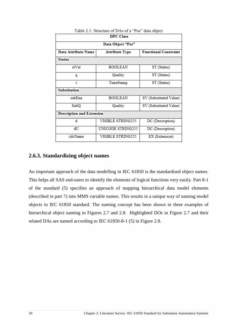
Each CDC has a group of attributes that belongs to a fixed group of functional constraints (FC).
In other word, each DO contains some Data Attributes (DA) with a Data Attribute Type
(DAType) that belongs to a set of Functional Constraints (FC). The FCs classify the attributes
into different categories. For instance, for a Circuit Breaker (XCBR), there are functional
constraints of Status (ST), Substituted Value (SV), Description (DC) and Extended definition
(EX) attributes. Table 2.1 shows the attributes of a DO for Switch Position (Pos) of a circuit
breaker function (XCBR). As per the Table 2.1, the status attributes of Double Point Control
class (DPC) for a “Pos” data object contain a status value (stVal), a quality flag (q) and a time
stamp (t).
20 Chapter 2: Literature Survey- IEC 61850 Standard for Substation Automation Systems
Table 2.1: Structure of DAs of a “Pos” data object
2.6.3. Standardizing object names
An important approach of the data modelling in IEC 61850 is the standardised object names.
This helps all SAS end-users to identify the elements of logical functions very easily. Part 8-1
of the standard (5) specifies an approach of mapping hierarchical data model elements
(described in part 7) into MMS variable names. This results in a unique way of naming model
objects in IEC 61850 standard. The naming concept has been shown in three examples of
hierarchical object naming in Figures 2.7 and 2.8. Highlighted DOs in Figure 2.7 and their
related DAs are named according to IEC 61850-8-1 (5) in Figure 2.8.

Chapter 2: Literature Survey- IEC 61850 Standard for Substation Automation Systems 21
Figure 2.7: Structure of hierarchical object model in IEC 61850
Figure 2.8: Examples of object naming for highlighted DOs in figure 2.7 according to IEC 61850-8-1

22 Chapter 2: Literature Survey- IEC 61850 Standard for Substation Automation Systems
Figure 2.9 shows the same current and voltage measurement functions used in Figure 2.7 and
their names in the explorer layout.
Figure 2.9: Explorer layout for object naming of Current and Voltage measurement functions
All functions in multifunctional IEDs are modelled in the similar approach and grouped in
related LNs.
2.7. Communication in IEC 61850
2.7.1. Communication stack and mapping to real protocols
Communication stack is a key feature in IEC 61850. It is a group of protocols working together
to enable all IEDs to behave identically on the network environment. As discussed in Section
1.5, part 7 of the IEC 61850 standard defines data models for different applications in a SA
system to achieve interoperability between IEDs. However, these models must be able to
operate over real protocols that are currently used in the power industry (13). Part 7-2 (21) of
the standard defines the Abstract Communication Service Interface (ACSI) models and
describes common utility services for IEC 61850 compatible devices for peer to peer and client-

Chapter 2: Literature Survey- IEC 61850 Standard for Substation Automation Systems 23
server communication. Part 8-1 (5) defines the mapping technique of IEC 61850 abstract
objects and services to real protocols including MMS (Manufacturing Message Specification
of ISO9506), TCP/IP (transmission control protocol/Internet protocol) and Ethernet. Figure
2.10 shows an overview of communication stack in part 8-1 of IEC 61850 standard (5).
Figure 2.10: Overview of IEC 61850 Protocol Stack structure (Page 19 of IEC 61850-8-1 standard
document (5))
2.7.2. Client-Server and Peer-Peer communications
2.7.2.1. GOOSE and MMS
There are two types of data transfer required in the SA system from the communication speed
perspective.
1- Basic communication services that transfer large blocks of data for configuration or
monitoring of the IEDs. These services are mapped to the MMS through TCP/IP and
ISO CO protocol (25). ACSI as defined in IEC 61850-7-2 (21), describes a set of
services that provide client-server type interaction between applications and servers in
a SA system (vertical communication) (25). Client-server communication makes the
data transmission very flexible as it is the client that controls the data exchange with
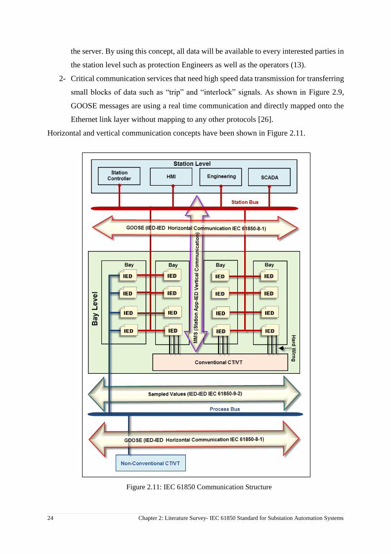
24 Chapter 2: Literature Survey- IEC 61850 Standard for Substation Automation Systems
the server. By using this concept, all data will be available to every interested parties in
the station level such as protection Engineers as well as the operators (13).
2- Critical communication services that need high speed data transmission for transferring
small blocks of data such as “trip” and “interlock” signals. As shown in Figure 2.9,
GOOSE messages are using a real time communication and directly mapped onto the
Ethernet link layer without mapping to any other protocols [26].
Horizontal and vertical communication concepts have been shown in Figure 2.11.
Figure 2.11: IEC 61850 Communication Structure

Chapter 2: Literature Survey- IEC 61850 Standard for Substation Automation Systems 25
MMS was chosen for client-server communication (vertical communication) as it supports
complex naming and has a set of flexible services which makes the easier mapping in IEC
61850. However as it relies on the full seven layers OSI (Open System Interconnection) stack,
it is very reliable but relatively time consuming. So it is not suitable for critical data
transmission (12).
On the other hand Generic Substation Event (GSE) was chosen to cover fast and reliable peer-
peer communication between IEDs (horizontal communication). GSE was introduced to
replace hard wiring between IEDs in conventional substations. There are two types of GSE
services;
1- Generic Substation State Event (GSSE) which was built in the standard to provide
backward compatibility to the UCA (Utility Communication Architecture) services and
only contains the state information in the Data Set.
2- Generic Object Oriented Substation Event (GOOSE) in turn supports not only state of
information but also different types of data in the standard. IEC 61850-8-1 defines
GOOSE messages to cover horizontal peer-peer IED communication. An IED can use
GOOSE messages to pack required information into a Data Set (DS) that typically
contains binary status indications and other data such as measured values.
By using the GOOSE concept, the end-users eliminate a large amount of physical wiring by
only a network cable. Commissioning will be also easier as the wiring check reduces to a few
network connections.
As mentioned earlier, part 8-1 of the standard (5) maps the GOOSE messages onto the Ethernet
straightaway without involving any other protocols. So the signals such as “trip” messages can
be sent via GOOSE instead of slow nature MMS protocol.
IEC 61850-8-1 (page 114 of (5)) describes the structure of the GOOSE message that is linked
with three layer of OSI model (Physical, Data link and Application layers). GOOSE messages
work based on broadcast of multicast messages across the Local Area Network (LAN) using
Publisher- Subscriber model. GOOSE publisher IEDs broadcast the GOOSE messages on the
multicast Media Access Control (MAC) addresses and subscriber IEDs listen to the network
traffic to pick their related data.
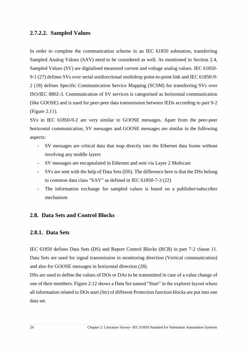
26 Chapter 2: Literature Survey- IEC 61850 Standard for Substation Automation Systems
2.7.2.2. Sampled Values
In order to complete the communication scheme in an IEC 61850 substation, transferring
Sampled Analog Values (SAV) need to be considered as well. As mentioned in Section 2.4,
Sampled Values (SV) are digitalised measured current and voltage analog values. IEC 61850-
9-1 (27) defines SVs over serial unidirectional multidrop point-to-point link and IEC 61850-9-
2 (18) defines Specific Communication Service Mapping (SCSM) for transferring SVs over
ISO/IEC 8802-3. Communication of SV services is categorised as horizontal communication
(like GOOSE) and is used for peer-peer data transmission between IEDs according to part 9-2
(Figure 2.11).
SVs in IEC 61850-9-2 are very similar to GOOSE messages. Apart from the peer-peer
horizontal communication, SV messages and GOOSE messages are similar in the following
aspects:
- SV messages are critical data that map directly into the Ethernet data frame without
involving any middle layers
- SV messages are encapsulated in Ethernet and sent via Layer 2 Multicast
- SVs are sent with the help of Data Sets (DS). The difference here is that the DSs belong
to common data class “SAV” as defined in IEC 61850-7-3 (22)
- The information exchange for sampled values is based on a publisher/subscriber
mechanism
2.8. Data Sets and Control Blocks
2.8.1. Data Sets
IEC 61850 defines Data Sets (DS) and Report Control Blocks (RCB) in part 7-2 clause 11.
Data Sets are used for signal transmission in monitoring direction (Vertical communication)
and also for GOOSE messages in horizontal direction (28).
DSs are used to define the values of DOs or DAs to be transmitted in case of a value change of
one of their members. Figure 2.12 shows a Data Set named “Start” in the explorer layout where
all information related to DOs start (Str) of different Protection function blocks are put into one
data set.
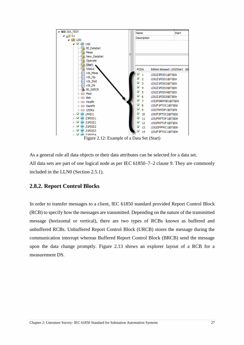
Chapter 2: Literature Survey- IEC 61850 Standard for Substation Automation Systems 27
Figure 2.12: Example of a Data Set (Start)
As a general rule all data objects or their data attributes can be selected for a data set.
All data sets are part of one logical node as per IEC 61850–7–2 clause 9. They are commonly
included in the LLN0 (Section 2.5.1).
2.8.2. Report Control Blocks
In order to transfer messages to a client, IEC 61850 standard provided Report Control Block
(RCB) to specify how the messages are transmitted. Depending on the nature of the transmitted
message (horizontal or vertical), there are two types of RCBs known as buffered and
unbuffered RCBs. Unbuffered Report Control Block (URCB) stores the message during the
communication interrupt whereas Buffered Report Control Block (BRCB) send the message
upon the data change promptly. Figure 2.13 shows an explorer layout of a RCB for a
measurement DS.
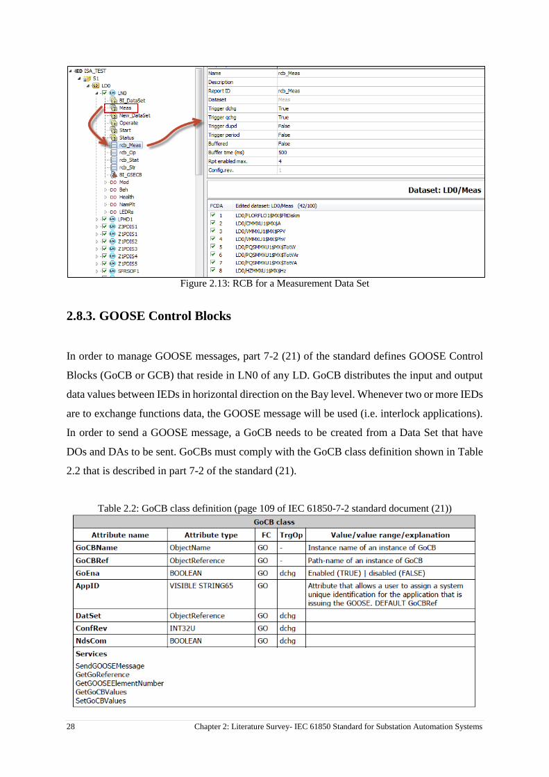
28 Chapter 2: Literature Survey- IEC 61850 Standard for Substation Automation Systems
Figure 2.13: RCB for a Measurement Data Set
2.8.3. GOOSE Control Blocks
In order to manage GOOSE messages, part 7-2 (21) of the standard defines GOOSE Control
Blocks (GoCB or GCB) that reside in LN0 of any LD. GoCB distributes the input and output
data values between IEDs in horizontal direction on the Bay level. Whenever two or more IEDs
are to exchange functions data, the GOOSE message will be used (i.e. interlock applications).
In order to send a GOOSE message, a GoCB needs to be created from a Data Set that have
DOs and DAs to be sent. GoCBs must comply with the GoCB class definition shown in Table
2.2 that is described in part 7-2 of the standard (21).
Table 2.2: GoCB class definition (page 109 of IEC 61850-7-2 standard document (21))

Chapter 2: Literature Survey- IEC 61850 Standard for Substation Automation Systems 29
Figure 2.14 shows an explorer layout of a GoCB that transmits binary status of the inputs of
function block GGIO.
Figure 2.14: Explorer layout of a GoCB (GCB) consists of DAs for binary status of a function block
2.9. Substation Configuration description Language (SCL)
2.9.1. SCL General Concept
Part 6 of IEC 61850 standard (29) defines a description language to describe how 61850-
compatible IEDs are configured in SA systems. This language is called Substation
Configuration description Language (SCL) and is used to describe IED configurations and
communication systems according to IEC 61850-5 (30) and IEC 61850-7-x (22,23 & 27).
SCL defines a formal relationship between the SAS functions (LNs) and substation elements
(switchyard). SCL also enables the description of an IED to be communicated by the
engineering software tools at station level and pass the complete system configuration back to
the IED at the Bay level over the SA network. Briefly, SCL describes all IED capabilities and
SA communication services in a formal unambiguous way.
SCL language is based on eXtensible Markup Language (XML). Each SCL XML file contains
5 following parts which are defined in SCL syntax elements in Clause 9 of IEC 61850-6 (29).
Clause 9.1 Header serves to identify an SCL configuration file and its version, and to specify
options for the mapping of names to the signals.
Clause 9.2 Substation description defines the functional structure and its relation to primary
devices. It also has used LNs and their relation to the primary equipment.
30 Chapter 2: Literature Survey- IEC 61850 Standard for Substation Automation Systems
Clause 9.3 IED description covers a definition of the complete IED as it is required for SA
communication services, the access points and the IEDs logical devices, LNs and their DAs.
Clause 9.4 Communication system description describes the connection between the IED
access points to the respective sub-network and includes also the properties (addresses) of the
access points.
Clause 9.5 Data type templates contain a declaration of all types used in the SCL file, LN
type, DO types and Das (29).
2.9.2. Engineering concept of SCL in IEC 61850-6
IEC 61850-6 edition 2 (29) introduces four types of common files. Based on a System
Specification Description (SSD) and IED Capability Description (ICD) files, the system
configuration tool is used to configure the substation. The result is the Substation Configuration
Description (SCD) file that is then used in IED configuration tools to generate Configured IED
Description (CID) that will be downloaded to the IEDs. All these files are in XML format and
built in the same ways and format but have different scopes depending on the requirements.
SCL files are categorised in the following types:
1 - IED Capability Description (ICD) file: It defines complete capability of an IED.
This file needs to be supplied by each manufacturer to make the complete system
configuration.
2 - System Specification Description (SSD) file: This file contains complete
specification of a substation automation system including single line diagram for
the substation and its functionalities (logical nodes).
3 - Substation Configuration Description (SCD) file: This is the file describing
complete substation detail.
4 - Configured IED Description (CID) file: It is a file used to have communication
between an IED configuration tool and an IED. It can be considered as an SCD file
stripped down to what the concerned IED need to know and contains a mandatory
communication section of the addressed IED.
Edition 2 of IEC 61850-6 (29) has also introduced two new XML files as follows;
1 - Instantiated IED Description (IID) file: It defines the configuration of one IED for
a project and is used as data exchange format from the IED configurator to the
system configurator.

Chapter 2: Literature Survey- IEC 61850 Standard for Substation Automation Systems 31
2 - System Exchange Description (SED) file: This file is to be exchanged between
system configurators of different projects. It describes the interfaces of one project
to be used by another project, and at re-import the additionally engineered interface
connections between the projects (29).
Figure 2.15 shows engineering process with the SCL language.
Figure 2.15: The use of Substation Configuration Language (SCL)
Conclusion
This chapter gives a comprehensive literature survey which reviews the existing knowledge and
research activities in the IEC 61850 standard. The key definitions of the standard are elaborated in
details using the IEC standard documentation. History and benefits of IEC 61850 standard are also
outlined. Structure of a 61850-compatible substation including different application levels is explained
using examples and figures. Protocol stack and mapping technique, the usage of GOOSE messages and
XML based SCL language are discussed through examples and figures.
32 Chapter 3: Analysis
Chapter 3: Analysis
Introduction
This chapter gives an introduction about hardware and software tools used to accomplish this
research. The overview list of the equipment that are used to run the test bed is as follows:
1. Distance protection relay, Protecta EuroProt+/DTVA
2. EuroCap software to configure protection functions and IEC 61850 parameters (IED
Configuration tool)
3. ISA DRTS66 secondary injection test set
4. ISA TDMS software to configure test set and IEC 61850 parameters
5. Wireshark Network Analyzer software
6. Ethernet switch to simulate station Bus
The background, operation and functions of each equipment and tool are discussed in the
following sections.
3.1. Protection Relay
Distance protection relay DTVA from EuroProt+ family is used as a core device in this research
to test the station level functions. This IED is a multifunction relay however only the Distance
protection function is used for this project.
3.1.1. Background
Protecta Ltd. is a Hungarian manufacturer of protection relays that provides IEDs for protection
and control of medium and high voltage of the power systems. The EuroProt+ series of IEDs
produced by Protecta draws on more than 50 years’ experience in the field of efficient
protection relaying. The new platform is a straightforward evolution of Protecta's previous
product families of digital protection technology and it compares favorably with the market
leaders products. Rising to the challenge of the revolution of the IP technology, the EuroProt+
extends the system to a platform using IP based HMI functions and to IEDs with native
IEC61850 features (31).

Chapter 3: Analysis 33
A DTVA distance protection relay of EuroProt+ family is shown in Figure 3.1. EuroProt+
family is native IEC 61850 that directly supports the standard without any external gateway or
embedded converter module (31).
Figure 3.1: EuroProt+/DTVA Distance protection relay (31)
The practical implementation of the IEC 61850 standard was done using EuroProt+ relay.
3.1.2. Distance Protection in EuroProt+ DTVA series
EuroProt+ is a multifunction protection relay that supports various protection functions. DTVA
series of EuroProt+ was designed for distribution and transmission feeder protection and
control applications. This series provide full functionality for power lines and cables including
5-zone distance protection of quadrilateral or Mho characteristics and 2 or 3 end line
differential function. The main features of the relays belong to DTVA series are:
Web interface tool for complete device handling
High capacity heavy duty trip contacts: 4A 220V DC breaking capacity
Enhanced breaker monitoring
Built-in PLC for user logic
Full bay control feature (31)
The EuroProt+ DTVA relays measure three phase currents and voltages and sequence
components of the protected feeders. These measurements allow, in addition to the current and
voltage based functions, directionality extension of the configured phase and residual
overcurrent function and also directional overpower or underpower functions. The main
protection function in this application is the distance protection function. The distance
protection function can generate three-phase or single-phase trip commands, depending on the
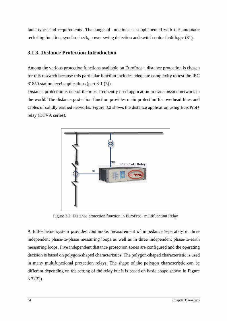
34 Chapter 3: Analysis
fault types and requirements. The range of functions is supplemented with the automatic
reclosing function, synchrocheck, power swing detection and switch-onto- fault logic (31).
3.1.3. Distance Protection Introduction
Among the various protection functions available on EuroProt+, distance protection is chosen
for this research because this particular function includes adequate complexity to test the IEC
61850 station level applications (part 8-1 (5)).
Distance protection is one of the most frequently used application in transmission network in
the world. The distance protection function provides main protection for overhead lines and
cables of solidly earthed networks. Figure 3.2 shows the distance application using EuroProt+
relay (DTVA series).
Figure 3.2: Distance protection function in EuroProt+ multifunction Relay
A full-scheme system provides continuous measurement of impedance separately in three
independent phase-to-phase measuring loops as well as in three independent phase-to-earth
measuring loops. Five independent distance protection zones are configured and the operating
decision is based on polygon-shaped characteristics. The polygon-shaped characteristic is used
in many multifunctional protection relays. The shape of the polygon characteristic can be
different depending on the setting of the relay but it is based on basic shape shown in Figure
3.3 (32).

Chapter 3: Analysis 35
Figure 3.3: Distance protection Polygon-shaped characteristics (32)
Table 3.1 shows the names used for protection function / LN as introduced in IEC61850-7-4
(23) and IEEE C37.2 (33).
Table 3.1: Distance protection names in IEEE and IEC 61850 standards
Protection Function IEEE C37.2 Function
Number
IEC 61850 Logical Node
Distance Protection 21 PDIS
In order to classify whether the calculated fault is inside or outside of a protection zone,
distance zones are used. A distance protection relay normally has different zones used for
different purposes. This is called step distance schemes and have at least three zones. These
three zones have been developed to allow satisfactory discrimination to protect transmission
lines with distance protection function.
- The first zone trips with no time delay and extends from the protection relay point to a
location just short of the remote busbar. This is commonly set to 80-90% of the line
impedance.
- Second zone is to provide remote backup protection for the remainder of line including
next zone in the protection scheme, which is commonly the remote busbar. Minimum
reach setting 120% of the line impedance is usually applied with a timer setting of
400/600 milliseconds (15-30 cycles) for transmission circuits.
- The third zone reaches beyond zone 2 and is configured to provide remote backup for
equipment failure embedded at remote terminal (Figure 3.4).
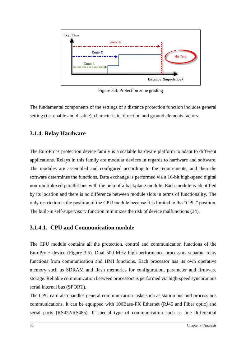
36 Chapter 3: Analysis
Figure 3.4: Protection zone grading
The fundamental components of the settings of a distance protection function includes general
setting (i.e. enable and disable), characteristic, direction and ground elements factors.
3.1.4. Relay Hardware
The EuroProt+ protection device family is a scalable hardware platform to adapt to different
applications. Relays in this family are modular devices in regards to hardware and software.
The modules are assembled and configured according to the requirements, and then the
software determines the functions. Data exchange is performed via a 16-bit high-speed digital
non-multiplexed parallel bus with the help of a backplane module. Each module is identified
by its location and there is no difference between module slots in terms of functionality. The
only restriction is the position of the CPU module because it is limited to the “CPU” position.
The built-in self-supervisory function minimizes the risk of device malfunctions (34).
3.1.4.1. CPU and Communication module
The CPU module contains all the protection, control and communication functions of the
EuroProt+ device (Figure 3.5). Dual 500 MHz high-performance processors separate relay
functions from communication and HMI functions. Each processor has its own operative
memory such as SDRAM and flash memories for configuration, parameter and firmware
storage. Reliable communication between processors is performed via high-speed synchronous
serial internal bus (SPORT).
The CPU card also handles general communication tasks such as station bus and process bus
communications. It can be equipped with 100Base-FX Ethernet (RJ45 and Fiber optic) and
serial ports (RS422/RS485). If special type of communication such as line differential

Chapter 3: Analysis 37
protection via Ethernet or telecommunication is required, COM+ module will be used (34).
Figure 3.5: CPU and communication board (35)
3.1.4.2. Human Machine Interface (HMI) module
The HMI in EuroProt+ devices consists of the two main parts:
1- HMI module, which is the front panel of the device
2- HMI functionality is the embedded web server and the intuitive menu system that is
accessible through the HMI module. The web server is available via station bus, EOB
(Optical Ethernet Over Board) interface or RJ-45 Ethernet connector (34).
Figure 3.6 shows the details of front panel interface of HMI module.
Figure 3.6: EuroProt+ HMI module (34)

38 Chapter 3: Analysis
3.1.4.3. Power Supply Unit
Power supply module converts primary AC or DC primary voltage to required system voltages.
In most cases of applications one power supply card is enough to provide the required power
to the system. Redundant power supply cards extend system availability in case of outage of
any power source. Main features of the standard power supply modules are:
30W and 60W power versions (PS+1030, PS+1060)
80V-300VDC input range, AC power also supported (36)
3.1.4.4. Analog Input cards (Current and Voltage modules)
Current module is an input card with intermediate current transformers to input the phase
currents and the zero sequence current. The rated current for the phase current and for the zero
sequence current can be selectable by parameter.
If the device performs voltage related functions (over/under-voltage, directionality, distance
protection) or the voltage is to be sampled for the disturbance recorder, then Voltage module
is needed (34).
3.1.4.5. Digital Input card (Binary Input module)
The inputs are galvanic isolated and the module converts high-voltage signals to the voltage
level and format of the internal circuits. This module is also used as an external IRIG-B
synchronization or PPM (Pulse Per Minute) input. Dedicated synchronization input is used for
this purpose (34).
3.1.4.6. Digital Output cards (Signaling and tripping modules)
The signaling module has 4, 8, 12 or 16 relay outputs with dry contacts. The tripping module
is a proprietary and patented Protecta solution that facilitates direct control of a circuit breaker
(34). These modules are not used in this project as output signals including trip commands are
sent via GOOSE messages over the station bus.

Chapter 3: Analysis 39
3.1.5. IED Configuration Tool (EuroCap)
The EuroCap software is the general IED configuration tool for the EuroProt+ devices. This is
the Microsoft Windows based program and used to manage the hardware and software included
in the device. From the hardware and software perspective, the EuroProt+ family is modular.
These modules are assembled and configured according to the user requirements, then the
functions of the device are determined by the software and parameter values (37). Hardware
and software structure of EuroProt+ family is shown in Figure 3.7.
Figure 3.7: Hardware and software structure of EuroProt+ family (37)
3.1.5.1. Hardware Configuration tool (Rack Designer)
Rack designer program is a tool in EuroCap software that is used to select and assemble the
hardware modules required for particular protection and control applications, Figure 3.8. An
IED consists of:
Rack size of which can be selected (full size or half size)
Front panel, the size of which is to be matched to the rack
Bus panel, the size of which is to be matched to the rack
Several hardware modules (37)
Rack designer tool allows the end user to add/remove hardware modules or modify the factory
configuration module arrangement.

40 Chapter 3: Analysis
Figure 3.8: Modifying factory configuration in rack designer tool (half size version)
All possible hardware types are found in the hardware library. Figure 3.9 shows the selection
of the binary output modules as an example.
Figure 3.9: Module selection window showing the choice of the binary output modules
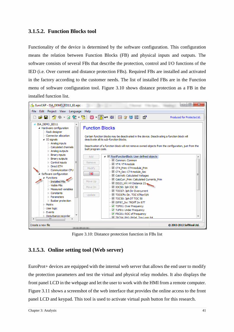
Chapter 3: Analysis 41
3.1.5.2. Function Blocks tool
Functionality of the device is determined by the software configuration. This configuration
means the relation between Function Blocks (FB) and physical inputs and outputs. The
software consists of several FBs that describe the protection, control and I/O functions of the
IED (i.e. Over current and distance protection FBs). Required FBs are installed and activated
in the factory according to the customer needs. The list of installed FBs are in the Function
menu of software configuration tool. Figure 3.10 shows distance protection as a FB in the
installed function list.
Figure 3.10: Distance protection function in FBs list
3.1.5.3. Online setting tool (Web server)
EuroProt+ devices are equipped with the internal web server that allows the end user to modify
the protection parameters and test the virtual and physical relay modules. It also displays the
front panel LCD in the webpage and let the user to work with the HMI from a remote computer.
Figure 3.11 shows a screenshot of the web interface that provides the online access to the front
panel LCD and keypad. This tool is used to activate virtual push button for this research.

42 Chapter 3: Analysis
Figure 3.11: Web interface tool for online parameter setting and remote control
3.1.5.4. Matrix
The embedded web server in EuroProt+ family introduces the matrix concept. Matrix is used
to marshal the binary status of FBs’ outputs to the relay’s physical and virtual outputs (Figure
3.12).
In the rows of the matrix binary status signals of FBs are available and the columns of the
matrix are the outputs. These outputs can be applied in the graphical logic editor as input signals
[Section 3.1.5.6]. The user defines the assignments between rows and columns during the
parameter setting procedure.

Chapter 3: Analysis 43
Figure 3.12: Web interface tool for Matrix configuration
3.1.5.5. Offline setting tool (EuroSet)
The EuroCap configuration software provides a special tool for processing the parameter
settings of the EuroProt+ devices. The following operations are possible in offline setting
tool:
Reading the parameter values from a file
Modifying the parameter values in off-line mode
Saving the parameters to a file
Generating “RIO” files [Section 4.2.2.1] for testing the various protection functions
implemented in the EuroProt+ configurations.
This tool is used to produce the RIO file for the test set in the final test.
3.1.5.6. LCD Configuration tool (LCD Editor)
The “LCD Editor” tool generates the pictures for the front panel touchscreen LCD of EuroProt+
devices. A new LCD page can be created using predefined or new pictures and can be loaded
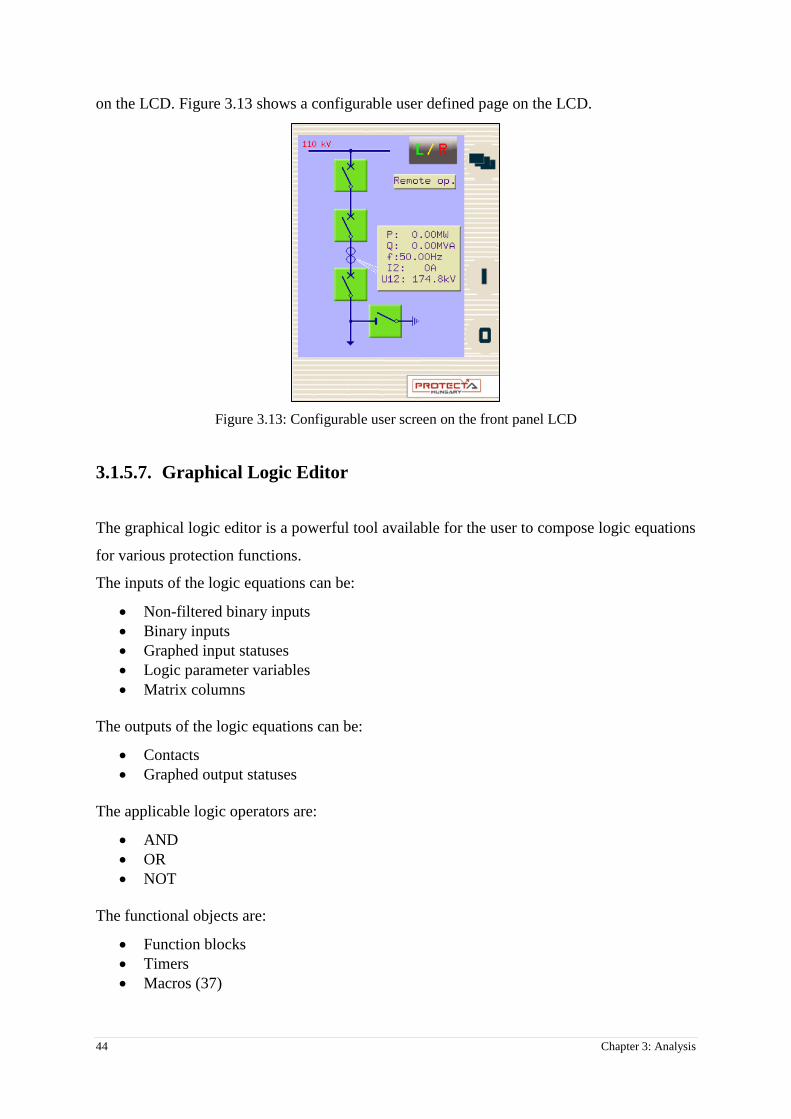
44 Chapter 3: Analysis
on the LCD. Figure 3.13 shows a configurable user defined page on the LCD.
Figure 3.13: Configurable user screen on the front panel LCD
3.1.5.7. Graphical Logic Editor
The graphical logic editor is a powerful tool available for the user to compose logic equations
for various protection functions.
The inputs of the logic equations can be:
Non-filtered binary inputs
Binary inputs
Graphed input statuses
Logic parameter variables
Matrix columns
The outputs of the logic equations can be:
Contacts
Graphed output statuses
The applicable logic operators are:
AND
OR
NOT
The functional objects are:
Function blocks
Timers
Macros (37)
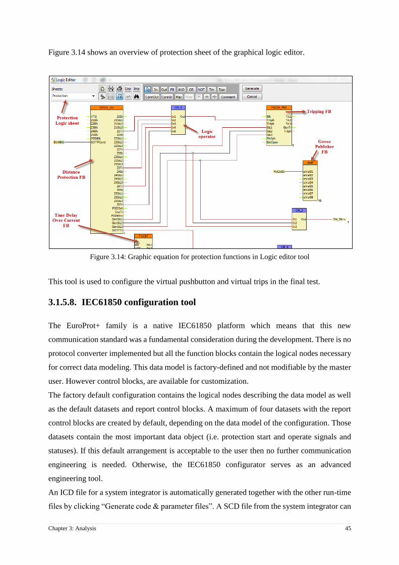
Chapter 3: Analysis 45
Figure 3.14 shows an overview of protection sheet of the graphical logic editor.
Figure 3.14: Graphic equation for protection functions in Logic editor tool
This tool is used to configure the virtual pushbutton and virtual trips in the final test.
3.1.5.8. IEC61850 configuration tool
The EuroProt+ family is a native IEC61850 platform which means that this new
communication standard was a fundamental consideration during the development. There is no
protocol converter implemented but all the function blocks contain the logical nodes necessary
for correct data modeling. This data model is factory-defined and not modifiable by the master
user. However control blocks, are available for customization.
The factory default configuration contains the logical nodes describing the data model as well
as the default datasets and report control blocks. A maximum of four datasets with the report
control blocks are created by default, depending on the data model of the configuration. Those
datasets contain the most important data object (i.e. protection start and operate signals and
statuses). If this default arrangement is acceptable to the user then no further communication
engineering is needed. Otherwise, the IEC61850 configurator serves as an advanced
engineering tool.
An ICD file for a system integrator is automatically generated together with the other run-time
files by clicking “Generate code & parameter files”. A SCD file from the system integrator can

46 Chapter 3: Analysis
also be accepted using the “Import” in IED Description menu.
As explained in Section 2.8 and according to IEC 61850 part 6 (29), integration process is
required for IEC 61850 systems. It is the preferred way to import the SCD file from substation
configuration tool into EuroCap software, however, it is also possible to do it manually. The
EuroProt+ device supplied with a default IEC61850 configuration. The functional LNs cannot
be changed by the end-user, they are “hardwired” to the device's function blocks. There is a
limited access to the LN names, prefix and suffix can be changed. The integrated
communication configuration software of the EuroCap grants the user to change the remaining
part of the data model: the IED name, the structure of logical devices, the datasets and reports
(37).
3.1.5.8.1. Data Model in IEC 61850 configuration tool
In the IEC 61850 configuration tool, the left pane displays the data model. Object names can
be changed in the DO tree or by using the property editor. Since some parameters are not
allowed to change, the editor tool denies the selection of them. Editable parameters are checked
against their constraints as the user leaves the field (37). Figure 3.15 shows the explorer view
of data model in IEC 61850 configuration tool.
Figure 3.15: Data model objects in explorer view in IEC 61850 Configuration tool
As discussed in Section 2.5.1, the communication configuration objects need to be placed in
the LN0 logical node inside the logical device. These objects are datasets, report control blocks
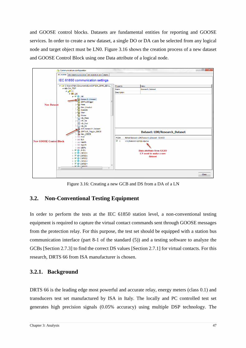
Chapter 3: Analysis 47
and GOOSE control blocks. Datasets are fundamental entities for reporting and GOOSE
services. In order to create a new dataset, a single DO or DA can be selected from any logical
node and target object must be LN0. Figure 3.16 shows the creation process of a new dataset
and GOOSE Control Block using one Data attribute of a logical node.
Figure 3.16: Creating a new GCB and DS from a DA of a LN
3.2. Non-Conventional Testing Equipment
In order to perform the tests at the IEC 61850 station level, a non-conventional testing
equipment is required to capture the virtual contact commands sent through GOOSE messages
from the protection relay. For this purpose, the test set should be equipped with a station bus
communication interface (part 8-1 of the standard (5)) and a testing software to analyze the
GCBs [Section 2.7.3] to find the correct DS values [Section 2.7.1] for virtual contacts. For this
research, DRTS 66 from ISA manufacturer is chosen.
3.2.1. Background
DRTS 66 is the leading edge most powerful and accurate relay, energy meters (class 0.1) and
transducers test set manufactured by ISA in Italy. The locally and PC controlled test set
generates high precision signals (0.05% accuracy) using multiple DSP technology. The

48 Chapter 3: Analysis
powerful current outputs (3 x 64 A at 860 VA) and voltage outputs (3 x 300 V at 100 VA)
allow to test any type of relays including old electromechanical relays. The DRTS66 test set
integrates the IEC61850 protocol interfaces for testing relays over Station Bus (part -8-1) and
Process Bus (part -9-2) of a substation (38). Figure 3.17 shows DRTS 66 equipment with IEC
61850-8-1 interface in the front panel.
Figure 3.17: DRTS 66 test equipment
DRTS 66 has a large graphical HMI display that allows the end-user to operate the test set
without using a computer. Major testing programs such as manual control, overcurrent and
distance can be performed through the front panel HMI. Figure 3.18 shows Distance test
program in the front panel interface.
Figure 3.18: Front panel interface for testing IEDs without using PC

Chapter 3: Analysis 49
DRTS 66 supports two PC interfaces (USB and Ethernet) that can be used to control the test
set from a local or remote PC with TDMS software. TDMS is a software package for testing
protection relays, energy and power quality meters and transducers [Section 3.2.3].
3.2.2. Hardware specification
Simultaneously available: 6 Current and 6
Voltage plus 1 battery simulator outputs
High current outputs: 6 x 32 A, 3 x 64 A, 1 x 128 A
High power outputs: 6 x 430 VA, 3 x 860 VA, 1 x 1000 VA
4 Binary Outputs Relays (AC: 300 V, 8 A, 2400 VA; DC: 300 V, 8 A, 50 W)
Internal memory 256 Mb internal memory suitable to store in the test set
approximately 2.000 test results.
High accuracy outputs: better than 0.05%
IEC61850 protocol interface
USB and Ethernet interface
Pen drive interface
IRIG-B interface for end-to-end tests (38)
3.2.3. Software tool
TDMS is a powerful software package providing data management for acceptance and
maintenance testing activities. Electrical apparatus data and test results are saved in the TDMS
database for historical results analysis. TDMS software organizes test data and results for the
majority of electrical apparatus tested with ISA test sets and related software. It also has a
powerful database that allows to create an electrical network with substations, feeders and the
majority of electrical apparatus such as Protective Relays, Instrument Transformers, Power
Transformers, Circuit Breakers, Energy Meters, Transducers, Power Quality Meters, Ground
Grids and Batteries.
3.2.4. Distance Protection testing program
TDMS software has a dedicated program for testing distance protection relays called “Distance
21” (Figure 3.19). “Distance 21” program is designed as a watch and play software, so the end-
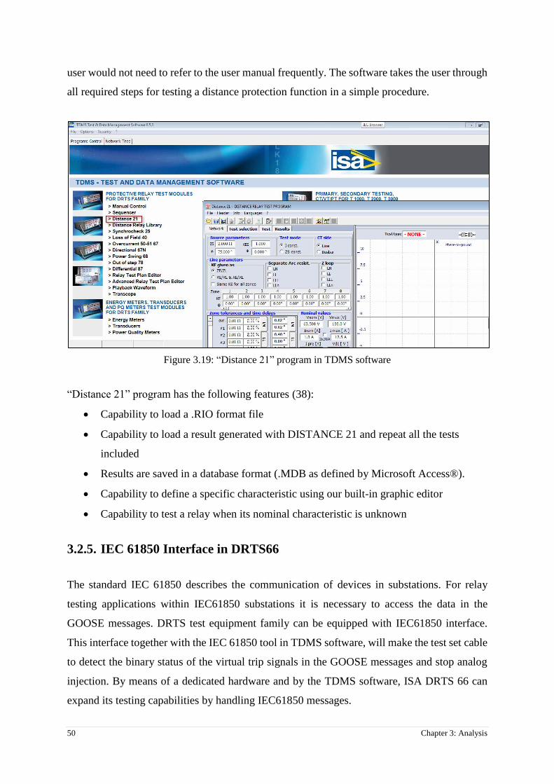
50 Chapter 3: Analysis
user would not need to refer to the user manual frequently. The software takes the user through
all required steps for testing a distance protection function in a simple procedure.
Figure 3.19: “Distance 21” program in TDMS software
“Distance 21” program has the following features (38):
Capability to load a .RIO format file
Capability to load a result generated with DISTANCE 21 and repeat all the tests
included
Results are saved in a database format (.MDB as defined by Microsoft Access®).
Capability to define a specific characteristic using our built-in graphic editor
Capability to test a relay when its nominal characteristic is unknown
3.2.5. IEC 61850 Interface in DRTS66
The standard IEC 61850 describes the communication of devices in substations. For relay
testing applications within IEC61850 substations it is necessary to access the data in the
GOOSE messages. DRTS test equipment family can be equipped with IEC61850 interface.
This interface together with the IEC 61850 tool in TDMS software, will make the test set cable
to detect the binary status of the virtual trip signals in the GOOSE messages and stop analog
injection. By means of a dedicated hardware and by the TDMS software, ISA DRTS 66 can
expand its testing capabilities by handling IEC61850 messages.

Chapter 3: Analysis 51
3.3. Network Analyzer software
In order to investigate the IEC 61850 messages transmitted between EuroProt+ relay as
GOOSE publisher and the test equipment as GOOSE subscriber [Section 2.6.2.1], there is a
need for a network analyzer software to capture the packets and provide tools to study the
contents of them. Wireshark is a powerful network protocol analysis suite that can capture and
interactively analyze the network traffic and runs on most platforms.
3.3.1. Background
Wireshark is a free and open-source packet analyzer that is used for network troubleshooting,
analysis, software development and education. Originally named Ethereal, in May 2006 the
project was renamed Wireshark due to trademark issues. Wireshark is cross-platform, using
the GTK+ (a cross-platform widget toolkit for creating graphical user interfaces (GUI)) in
current releases, and Qt (a cross-platform application framework that is widely used for
developing application software with a GUI) in the development version, to implement its user
interface, and using pcap (“packet capture” consists of an application programming
interface (API) for capturing network traffic) to capture packets; it runs on various Unix-like
operating systems including GNU/Linux, OS X (Mac OS), BSD (Berkeley Unix), and Solaris,
and on Microsoft Windows. There is also a terminal-based (non-GUI) version called TShark.
Wireshark and the other programs distributed with it such as TShark, are free software, released
under the terms of the GNU General Public License (39).
3.3.2. GOOSE filter
As described in Section 2.6.2.1, Generic Substation Events (GSE) is a control model defined
as per IEC 61850-8-1 which provides a fast and reliable mechanism of transferring event data
over electrical substation networks. GSE is providing the facility to transfer the same event
message to multiple physical devices using multicast / broadcast services. GSE control model
is further subdivided into GOOSE and GSSE. GOOSE data works based on publisher-
subscriber mechanism and is directly mapped into Ethernet data packets on multicast or
broadcast MAC addresses without involving any other protocols. GOOSE also uses Virtual
LAN (VLAN) and priority tagging according to IEEE 802.1Q (40) (the networking standard
that supports VLANs on an Ethernet network) to have separate virtual network within the same
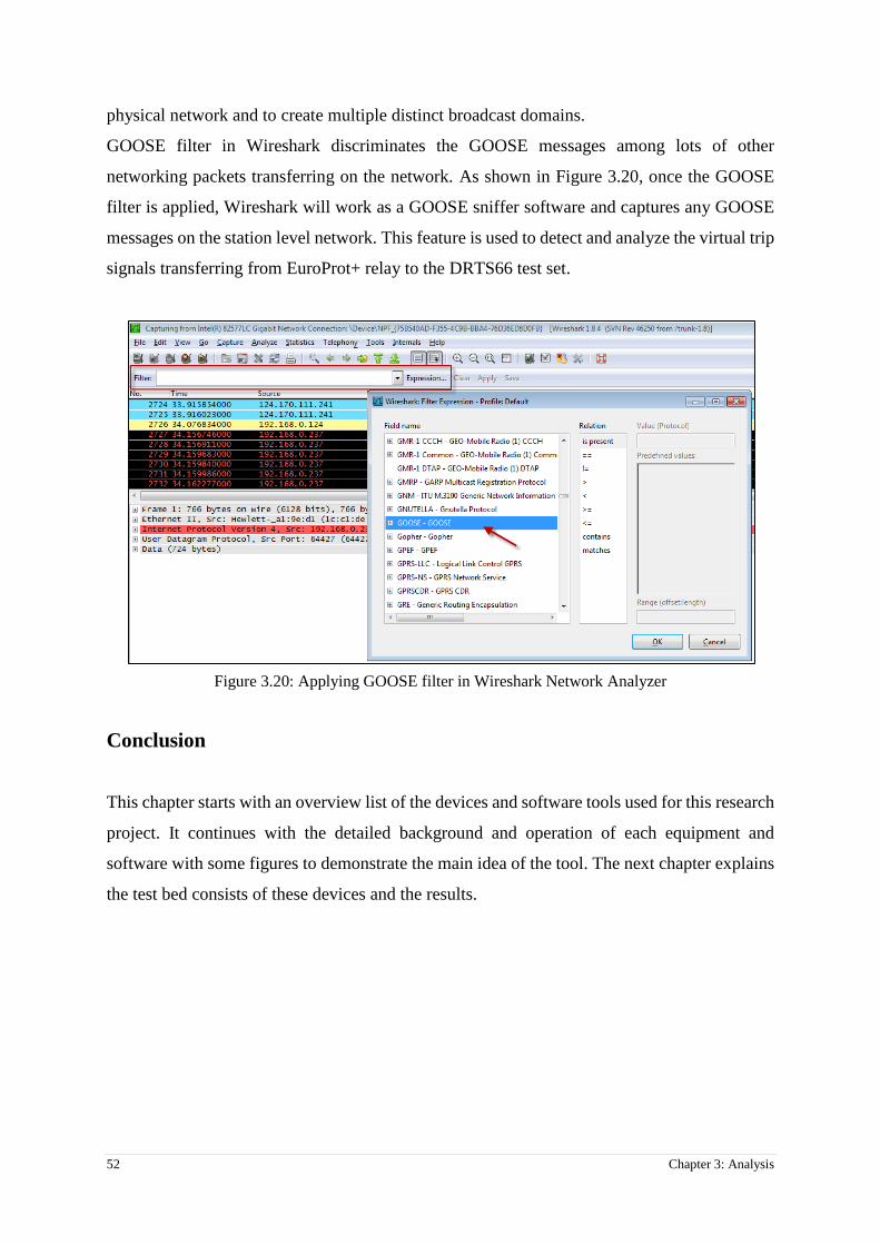
52 Chapter 3: Analysis
physical network and to create multiple distinct broadcast domains.
GOOSE filter in Wireshark discriminates the GOOSE messages among lots of other
networking packets transferring on the network. As shown in Figure 3.20, once the GOOSE
filter is applied, Wireshark will work as a GOOSE sniffer software and captures any GOOSE
messages on the station level network. This feature is used to detect and analyze the virtual trip
signals transferring from EuroProt+ relay to the DRTS66 test set.
Figure 3.20: Applying GOOSE filter in Wireshark Network Analyzer
Conclusion
This chapter starts with an overview list of the devices and software tools used for this research
project. It continues with the detailed background and operation of each equipment and
software with some figures to demonstrate the main idea of the tool. The next chapter explains
the test bed consists of these devices and the results.

Chapter 4: Laboratory work- Testing a Distance Protection Relay in IEC 61850-8-1 environment 53
Chapter 4: Laboratory work- Testing a Distance Protection Relay
in IEC 61850-8-1 environment
Introduction
This chapter provides the information of how the theory described in previous chapters comes
into practice. In order to achieve the goals of this research, such a practical work needs to be
performed. The key achievement of this research is to capture the GOOSE messages
transferring on the Station Bus between IEDs and study the DAs embedded in the GCBs. The
results help the test engineers/technicians to have a better understanding of what is going on in
the background of the testing software and IED configuration tool.
The practical work, first needs the basic theoretical structure of EuroProt+ Protection relay and
then utilizing that theory into practice. So the laboratory works are divided in two parts:
1- Pre-laboratory Works
2- Laboratory Works
Pre-laboratory works include the analysis of IEC 61850 standard, software tools and the
equipment used for the test bed. These have been discussed in chapter two and three of this
thesis. A further analysis on some relay logical functions such as GOOSE publisher FB still
require to be covered for the practical testing. This will be discussed in this chapter in details.
Laboratory works include testing 61850-compatible protection relay using a non-conventional
test set, then analyzing the GOOSE packets in a third party network analyzer software. This
will also be explained in this chapter.
4.1. Test structure
The test is to prove the GOOSE messages are sent correctly from the relay on the Station Bus
by analyzing the contents of GCBs. In order to provide a test bed for this purpose, the following
steps are done:

54 Chapter 4: Laboratory work- Testing a Distance Protection Relay in IEC 61850-8-1 environment
1- Preparation of tools
a. Software tools
i. Network GOOSE Explorer software (Wireshark)
ii. IED configuration tool (EuroCap)
iii. Test Equipment software (TDMS)
b. Hardware tools
i. IEC61850-compatible Protection Relay (EuroProt+)
ii. IEC61850-compatible Test equipment (ISA DRTS66)
iii. PC or Laptop to run the software tools
iv. Ethernet Switch to simulate station bus
2- Verifying the functionality of the GOOSE publisher function block in GOOSE
sender IED
a. Configuring GOOSE publisher Function Block (FB) in the Logic Editor
program in EuroCap software
b. Configuring GOOSE Control Blocks in Communication Configurator tool of
EuroCap software in order to check the Station Bus, Wireshark and TDMS
software
c. Exploring the GOOSE messages in the Network sniffer software (Wireshark)
to check the test Boolean values
3- Adjusting required configuration on the IED for Distance Protection
a. Setting parameters for distance protection function
b. Modifying Relay logics in “Logic Editor” program to assign the trip signal
output of Distance FB to GOOSE publisher FB inputs
c. Configuring IEC61850 parameters in Communication Configurator tool in
order to create new GCBs for virtual trips
4- Performing the test
a. Setting the same parameters in the testing program (TDMS- Distance21) that

Chapter 4: Laboratory work- Testing a Distance Protection Relay in IEC 61850-8-1 environment 55
are set on the EuroProt+ relay
b. Injecting analog values using test leads to the relay using the DRT 66 test set
c. Using GOOSE virtual trips to stop the analog injection through the IEC61850-
8-1 interface
Figure 4.1 illustrates the relay connections for this test and Figure 4.2 shows the actual test bed
that was set during the lab work.
Figure 4.1: Relay connection to IEC61850 Station Bus
Figure 4.2: Test bed for testing station level functions of an IEC 61850-compatible relay
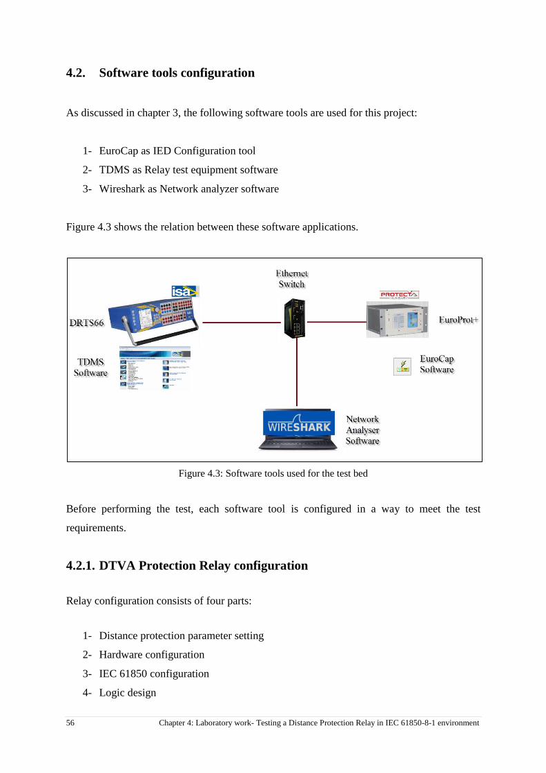
56 Chapter 4: Laboratory work- Testing a Distance Protection Relay in IEC 61850-8-1 environment
4.2. Software tools configuration
As discussed in chapter 3, the following software tools are used for this project:
1- EuroCap as IED Configuration tool
2- TDMS as Relay test equipment software
3- Wireshark as Network analyzer software
Figure 4.3 shows the relation between these software applications.
Figure 4.3: Software tools used for the test bed
Before performing the test, each software tool is configured in a way to meet the test
requirements.
4.2.1. DTVA Protection Relay configuration
Relay configuration consists of four parts:
1- Distance protection parameter setting
2- Hardware configuration
3- IEC 61850 configuration
4- Logic design
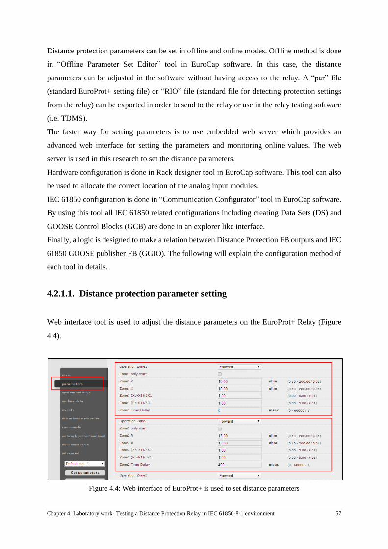
Chapter 4: Laboratory work- Testing a Distance Protection Relay in IEC 61850-8-1 environment 57
Distance protection parameters can be set in offline and online modes. Offline method is done
in “Offline Parameter Set Editor” tool in EuroCap software. In this case, the distance
parameters can be adjusted in the software without having access to the relay. A “par” file
(standard EuroProt+ setting file) or “RIO” file (standard file for detecting protection settings
from the relay) can be exported in order to send to the relay or use in the relay testing software
(i.e. TDMS).
The faster way for setting parameters is to use embedded web server which provides an
advanced web interface for setting the parameters and monitoring online values. The web
server is used in this research to set the distance parameters.
Hardware configuration is done in Rack designer tool in EuroCap software. This tool can also
be used to allocate the correct location of the analog input modules.
IEC 61850 configuration is done in “Communication Configurator” tool in EuroCap software.
By using this tool all IEC 61850 related configurations including creating Data Sets (DS) and
GOOSE Control Blocks (GCB) are done in an explorer like interface.
Finally, a logic is designed to make a relation between Distance Protection FB outputs and IEC
61850 GOOSE publisher FB (GGIO). The following will explain the configuration method of
each tool in details.
4.2.1.1. Distance protection parameter setting
Web interface tool is used to adjust the distance parameters on the EuroProt+ Relay (Figure
4.4).
Figure 4.4: Web interface of EuroProt+ is used to set distance parameters

58 Chapter 4: Laboratory work- Testing a Distance Protection Relay in IEC 61850-8-1 environment
For this project, distance parameters are set for a sample of 100km line. Table 4.1 shows the
parameters set in the relay for a four zones distance protection in this research.
Table 4.1: Distance parameters that set in the EuroProt+ relay for 100 km line
Operation Zone1 Forward
Zone1 R 9.00 ohm
Zone1 X 9.00 ohm
Zone1 (Xo-X1)/3X1 1.00
Zone1 (Ro-R1)/3R1 1.00
Zone1 Time Delay 20 msec
Operation Zone2 Forward
Zone2 R 12.00 ohm
Zone2 X 12.00 ohm
Zone2 (Xo-X1)/3X1 1.00
Zone2 (Ro-R1)/3R1 1.00
Zone2 Time Delay 300 msec
Operation Zone3 Forward
Zone3 R 16.00 ohm
Zone3 X 16.00 ohm
Zone3 (Xo-X1)/3X1 1.00
Zone3 (Ro-R1)/3R1 1.00
Zone3 Time Delay 600 msec
Operation Zone4 Backward
Zone4 R 5.00 ohm
Zone4 X 5.00 ohm
Zone4 (Xo-X1)/3X1 1.00
Zone4 (Ro-R1)/3R1 1.00
Zone4 Time Delay 1200 msec
4.2.1.2. Hardware configuration
Required configuration for physical input and output modules are done in Rack Designer tool.
If there is no hardware change, the factory default setting can be kept intact. However, this tool
is used to check the physical location of the analog input modules and the terminal numbers.
As shown in Figure 4.5, the voltage and current signals are injected from DRTS 66 through the

Chapter 4: Laboratory work- Testing a Distance Protection Relay in IEC 61850-8-1 environment 59
testing leads (no sampled Value of IEC 61850-9-1 is tested in this project).
VT+ 2211 Module is the Voltage Transformer (VT) inputs interface to get voltage values from
the VT secondary side in the field. These inputs are connected to the voltage generator outputs
on the DRTS66 test set.
CT+ 5151 Module is the Current Transformer (CT) inputs interface to get current values from
the CT secondary side in the field. These inputs are connected to the current generator outputs
of the DRTS66 test set.
Figure 4.5: Module arrangement of the Relay in “Rack Designer” program in EuroCap software
4.2.1.3. IEC 61850 configuration
In order to configure IEC 61850 parameters, “Communication Configurator” tool in EuroCap
software is used. This tool is also used to configure IEC 60870-5-101/104, IEC 60870-5-103
and DNP3. Figure 4.6 shows different protocols that can configured in this tool.

60 Chapter 4: Laboratory work- Testing a Distance Protection Relay in IEC 61850-8-1 environment
Figure 4.6: Communication Configurator tool for IEC 61850 configuration
4.2.1.3.1. Introducing GGIO Logical Node
IEC61850 standard provides standardised designations for input and output information.
Logical Node (LN) “GGIO” (Generic Process Input Output) is used to designate input and
output signals and replaces the conventional physical binary inputs and outputs. GGIO is a
compatible logical node for General IO according to IEC61850-7-4 (23). For this project, an
eight input GOOSE Publisher GGIO LN is used to send the trip outputs to the test set. Figure
4.7 shows the Data Objects (DO) of GGIO LN in explorer view in Communication
Configurator tool.
Figure 4.7: Data Objects in GGIO Logical Node
There is a suffix for each Data Object for example “Ind1” representing that the GGIO LN can
have eight virtual inputs (Ind, Ind2, Ind3 … Ind8). GGIO LN can be found as a function block
(FB) in the logic editor tool [Section 4.2.1.4]. These eight Data Objects represent the eight
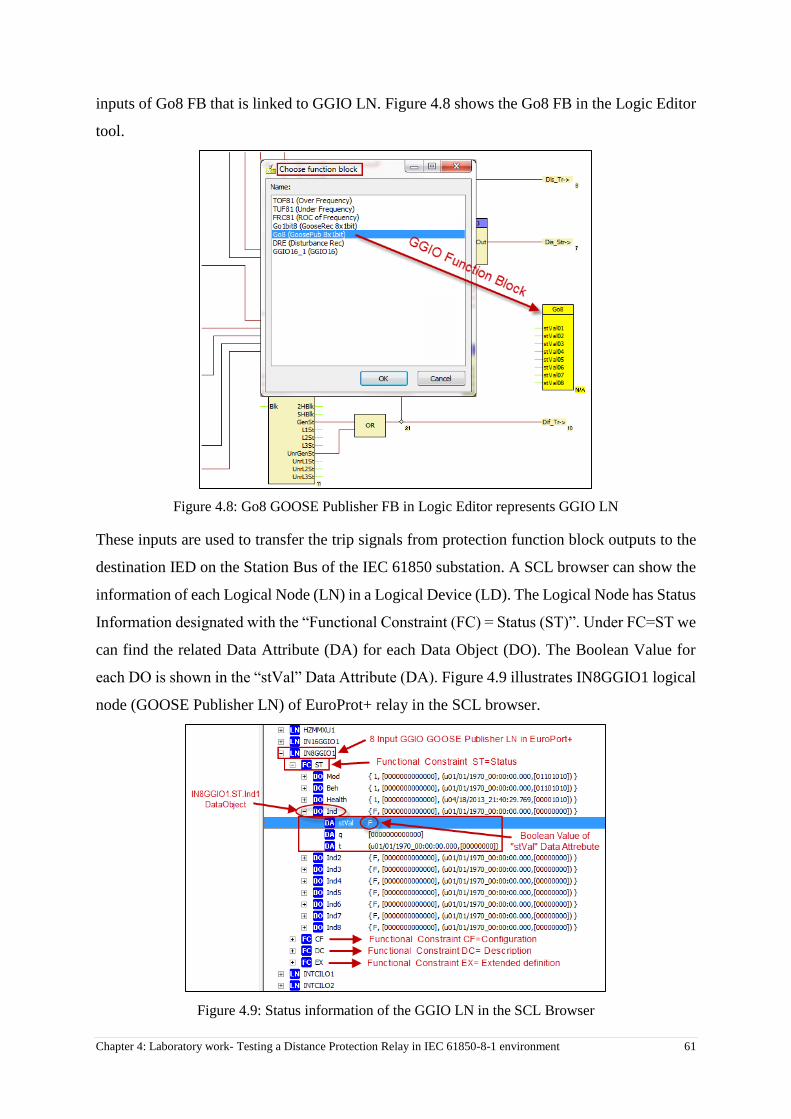
Chapter 4: Laboratory work- Testing a Distance Protection Relay in IEC 61850-8-1 environment 61
inputs of Go8 FB that is linked to GGIO LN. Figure 4.8 shows the Go8 FB in the Logic Editor
tool.
Figure 4.8: Go8 GOOSE Publisher FB in Logic Editor represents GGIO LN
These inputs are used to transfer the trip signals from protection function block outputs to the
destination IED on the Station Bus of the IEC 61850 substation. A SCL browser can show the
information of each Logical Node (LN) in a Logical Device (LD). The Logical Node has Status
Information designated with the “Functional Constraint (FC) = Status (ST)”. Under FC=ST we
can find the related Data Attribute (DA) for each Data Object (DO). The Boolean Value for
each DO is shown in the “stVal” Data Attribute (DA). Figure 4.9 illustrates IN8GGIO1 logical
node (GOOSE Publisher LN) of EuroProt+ relay in the SCL browser.
Figure 4.9: Status information of the GGIO LN in the SCL Browser
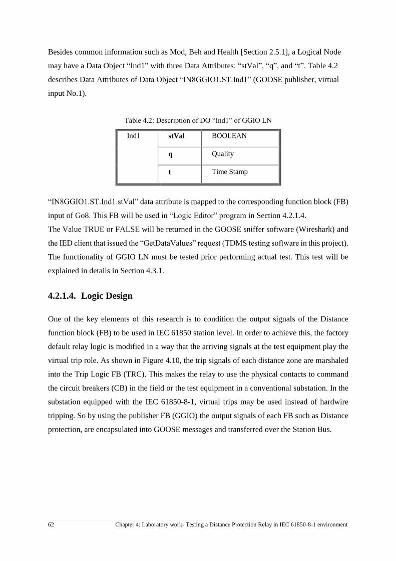
62 Chapter 4: Laboratory work- Testing a Distance Protection Relay in IEC 61850-8-1 environment
Besides common information such as Mod, Beh and Health [Section 2.5.1], a Logical Node
may have a Data Object “Ind1” with three Data Attributes: “stVal”, “q”, and “t”. Table 4.2
describes Data Attributes of Data Object “IN8GGIO1.ST.Ind1” (GOOSE publisher, virtual
input No.1).
Table 4.2: Description of DO “Ind1” of GGIO LN
Ind1 stVal BOOLEAN
q Quality
t Time Stamp
“IN8GGIO1.ST.Ind1.stVal” data attribute is mapped to the corresponding function block (FB)
input of Go8. This FB will be used in “Logic Editor” program in Section 4.2.1.4.
The Value TRUE or FALSE will be returned in the GOOSE sniffer software (Wireshark) and
the IED client that issued the “GetDataValues” request (TDMS testing software in this project).
The functionality of GGIO LN must be tested prior performing actual test. This test will be
explained in details in Section 4.3.1.
4.2.1.4. Logic Design
One of the key elements of this research is to condition the output signals of the Distance
function block (FB) to be used in IEC 61850 station level. In order to achieve this, the factory
default relay logic is modified in a way that the arriving signals at the test equipment play the
virtual trip role. As shown in Figure 4.10, the trip signals of each distance zone are marshaled
into the Trip Logic FB (TRC). This makes the relay to use the physical contacts to command
the circuit breakers (CB) in the field or the test equipment in a conventional substation. In the
substation equipped with the IEC 61850-8-1, virtual trips may be used instead of hardwire
tripping. So by using the publisher FB (GGIO) the output signals of each FB such as Distance
protection, are encapsulated into GOOSE messages and transferred over the Station Bus.

Chapter 4: Laboratory work- Testing a Distance Protection Relay in IEC 61850-8-1 environment 63
Figure 4.10: Trip signals of Distance FB in Logic Editor tool
4.2.1.5. Final Configuration for Distance protection and GOOSE publisher
FBs
The purpose of this stage is to design the relay logic as per Section 4.2.1.4 to make the relay
ready to interact in an IEC 61850-8-1 environment. In order to use the virtual outputs of GGIO
instead of conventional contacts, the following steps are done in “Logic Editor” and
“Communication Configurator” tools in EuroCap software.
4.2.1.5.1. Configuration in Logic Editor Program
Three phase trip output from Distance FB needs to be assigned to 8 inputs GGIO FB. So instead
of using trip logic FB (TRC_94), the 3 phase Distance trip output is assigned to GOOSE
publisher FB. Figure 4.11 shows this configuration.
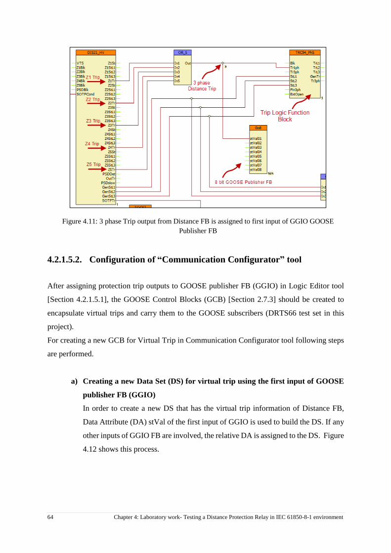
64 Chapter 4: Laboratory work- Testing a Distance Protection Relay in IEC 61850-8-1 environment
Figure 4.11: 3 phase Trip output from Distance FB is assigned to first input of GGIO GOOSE
Publisher FB
4.2.1.5.2. Configuration of “Communication Configurator” tool
After assigning protection trip outputs to GOOSE publisher FB (GGIO) in Logic Editor tool
[Section 4.2.1.5.1], the GOOSE Control Blocks (GCB) [Section 2.7.3] should be created to
encapsulate virtual trips and carry them to the GOOSE subscribers (DRTS66 test set in this
project).
For creating a new GCB for Virtual Trip in Communication Configurator tool following steps
are performed.
a) Creating a new Data Set (DS) for virtual trip using the first input of GOOSE
publisher FB (GGIO)
In order to create a new DS that has the virtual trip information of Distance FB,
Data Attribute (DA) stVal of the first input of GGIO is used to build the DS. If any
other inputs of GGIO FB are involved, the relative DA is assigned to the DS. Figure
4.12 shows this process.

Chapter 4: Laboratory work- Testing a Distance Protection Relay in IEC 61850-8-1 environment 65
Figure 4.12: State values (stVal) of the first input is used to make a new Data Set
b) Creating a new GCB for Virtual Trip using Virtual_Trip_Dataset
The DS created in the previous step, is now used to form a new GCB. So the existing
“Virtual_Trip_Dataset” is chosen from drop down menu, then other GCB
parameters such as name, ID and priority are set in the GCB properties. Figure 4.13
shows this process.
Figure 4.13: Creating a new GCB for Virtual Trip using the existing Dataset

66 Chapter 4: Laboratory work- Testing a Distance Protection Relay in IEC 61850-8-1 environment
4.2.2. Test Equipment setup
TDMS is a software to manage testing procedures for all ISA test equipment including primary
and secondary injection devices. Each function has a dedicated program in TDMS such as
CT/VT, overcurrent protection and Differential protection programs. In order to test a distance
scheme using a DRTS66 test set, “Distance 21” program is used. Figure 4.14 shows the main
interface of TDMS software.
Figure 4.14: ISA TDMS Test software
4.2.2.1. TDMS parameter setting
In order to test a distance scheme, distance parameters are set in the TDMS and zones
characteristics is defined in Z-Design program exactly as per protection relay settings.
Some relay manufacturers provides a tool in the relay management program to generate a
standard file containing all required information of the relay setting. This file is called RIO and
is used to transfer the operating characteristic of specific relays to the testing software. The
RIO files is imported into the Distacne21 program of TDMS software.
In order to retrieve the RIO file from EuroProt+ relay, the setting file is retrieved from web
interface and imported into “Offline Parameter Set Editor” of EuroCap. As per Figure 4.15,
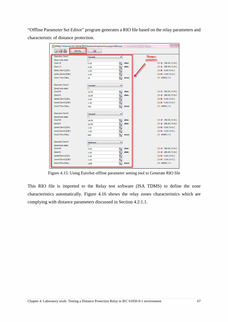
Chapter 4: Laboratory work- Testing a Distance Protection Relay in IEC 61850-8-1 environment 67
“Offline Parameter Set Editor” program generates a RIO file based on the relay parameters and
characteristic of distance protection.
Figure 4.15: Using EuroSet offline parameter setting tool to Generate RIO file
This RIO file is imported to the Relay test software (ISA TDMS) to define the zone
characteristics automatically. Figure 4.16 shows the relay zones characteristics which are
complying with distance parameters discussed in Section 4.2.1.1.
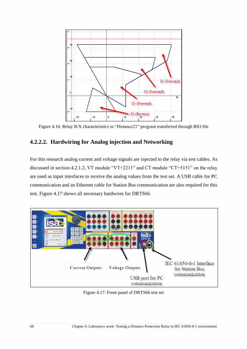
68 Chapter 4: Laboratory work- Testing a Distance Protection Relay in IEC 61850-8-1 environment
Figure 4.16: Relay R/X characteristics in “Distance21” program transferred through RIO file
4.2.2.2. Hardwiring for Analog injection and Networking
For this research analog current and voltage signals are injected to the relay via test cables. As
discussed in section 4.2.1.2, VT module “VT+2211” and CT module “CT+5151” on the relay
are used as input interfaces to receive the analog values from the test set. A USB cable for PC
communication and an Ethernet cable for Station Bus communication are also required for this
test. Figure 4.17 shows all necessary hardwires for DRTS66.
Figure 4.17: Front panel of DRTS66 test set

Chapter 4: Laboratory work- Testing a Distance Protection Relay in IEC 61850-8-1 environment 69
4.3. Test execution
In contribution to this research to test the protection relays in non-conventional environment,
the concept of virtual push button is suggested. Before starting the final test on the Distance
protection function, it is necessary to make sure that GGIO Function Block is publishing
GOOSE Control Blocks as expected and the Relay acts correctly as a GOOSE publisher IED
on the Station Bus. Consequently test execution consists of two parts.
1- Testing functionality of GGIO function
2- Testing Distance protection function using virtual trips and analyzing the GOOSE
signals in third party software
4.3.1. Testing functionality of GGIO FB
The following procedure describes the suggested method in this research for checking the
GOOSE packets. This method can be used to test any protection function of multifunction
EuroProt+ relay family without any test set and by only using a third party network analyzer
software (Wireshark). This method can also be expanded to any protection relays of different
manufacturer for testing the logic designed in the relay. As described in Section 3.3, Wireshark
is a free and open-source network packet analyzer that is used for network analysis. Wireshark
is also the kernel of most of IEC61850 simulator tools and SCL browsers.
As discussed in Section 3.1.5.5, web server of EuroProt+ provides a Matrix tool in its web
interface and allows the end-user to marshal any FB outputs to the internal virtual inputs in a
web browser such as MS Internet Explorer or Firefox. These internal virtual inputs, in turn, are
assigned to the physical/virtual outputs and LEDs.
The idea is to make two virtual pushbuttons that changes the status of some GGIO FB inputs.
The Data Sets (DS) will then carry the Data Attributes of GGIO inputs over the Station Bus in
the GCB packets. Finally, Wireshark will detect these GCBs with designated GOOSE IDs and
the change of Boolean values of DAs is checked. This will confirm the proper operation of the
GGIO FB which is the key element in this research. Using only one virtual push button could
confirm the proper functionality of GGIO FB, however, two virtual pushbuttons are used in
this research to illustrate how much this method is flexible to use different elements as the
signal source and how it can be expanded to test other relay functions. The first virtual

70 Chapter 4: Laboratory work- Testing a Distance Protection Relay in IEC 61850-8-1 environment
pushbutton is created by the help of Matrix tool and second one by simulating a Binary input
(BI). The fowling is the process of making and using these virtual push buttons.
4.3.1.1. Creating Virtual Pushbuttons
In order to make two virtual push buttons, the following steps are performed;
a. Creating a Matrix column for GOOSE publisher (Software configuration tool)
b. Creating a Matrix row as an “Always True” signal (Logic Editor and Software
configuration tools)
c. Creating a new GCB for pushbuttons (Communication Configurator tool)
d. Activating GGIO inputs for matrix column and BI (Logic Editor tool)
Each step is elaborated below;
4.3.1.1.1. Creating a Matrix column for GOOSE publisher
With the help of “Software configuration” tool in EuroCap software, a new matrix column is
created to represent one input of the GOOSE publisher FB. Figure 4.18 illustrates the process
of creating this matrix column in the numbering order. After updating the relay with the new
configuration, the name of this column “GoosePub” is shown in the Matrix section of the relay
web interface.
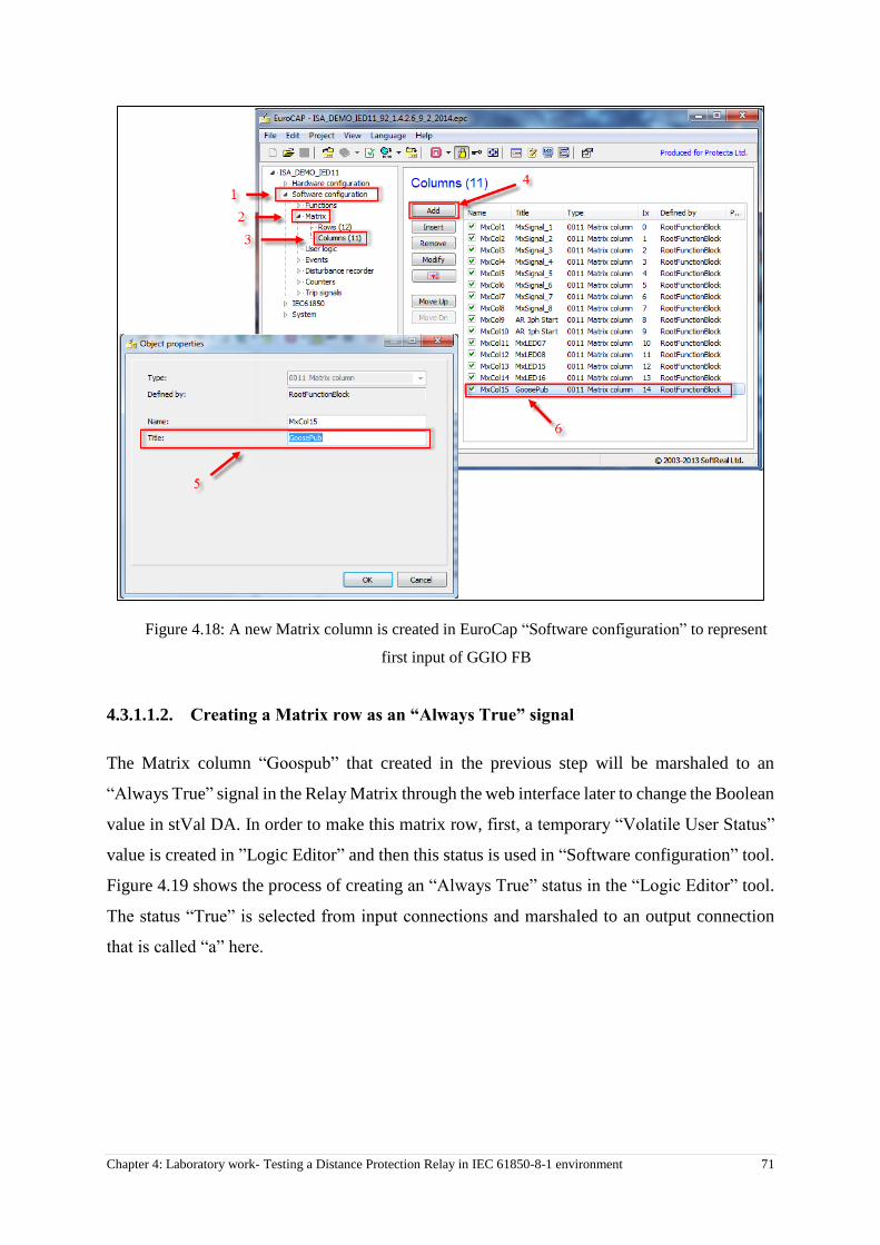
Chapter 4: Laboratory work- Testing a Distance Protection Relay in IEC 61850-8-1 environment 71
Figure 4.18: A new Matrix column is created in EuroCap “Software configuration” to represent
first input of GGIO FB
4.3.1.1.2. Creating a Matrix row as an “Always True” signal
The Matrix column “Goospub” that created in the previous step will be marshaled to an
“Always True” signal in the Relay Matrix through the web interface later to change the Boolean
value in stVal DA. In order to make this matrix row, first, a temporary “Volatile User Status”
value is created in ”Logic Editor” and then this status is used in “Software configuration” tool.
Figure 4.19 shows the process of creating an “Always True” status in the “Logic Editor” tool.
The status “True” is selected from input connections and marshaled to an output connection
that is called “a” here.
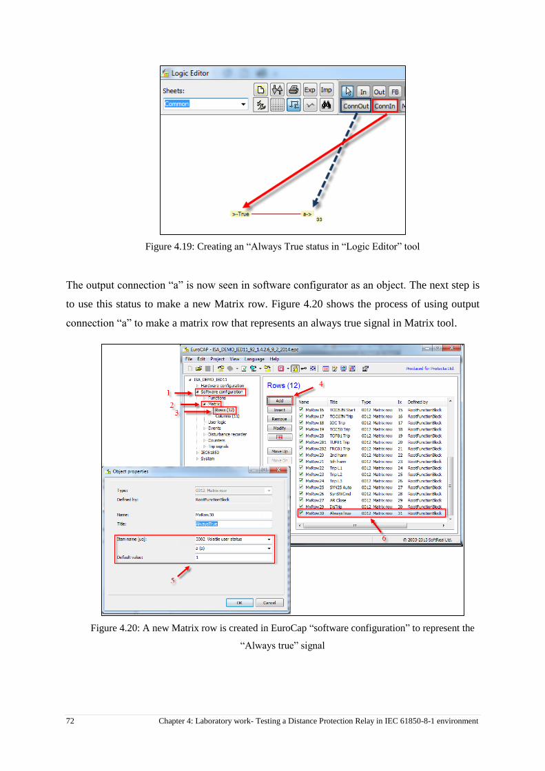
72 Chapter 4: Laboratory work- Testing a Distance Protection Relay in IEC 61850-8-1 environment
Figure 4.19: Creating an “Always True status in “Logic Editor” tool
The output connection “a” is now seen in software configurator as an object. The next step is
to use this status to make a new Matrix row. Figure 4.20 shows the process of using output
connection “a” to make a matrix row that represents an always true signal in Matrix tool.
Figure 4.20: A new Matrix row is created in EuroCap “software configuration” to represent the
“Always true” signal
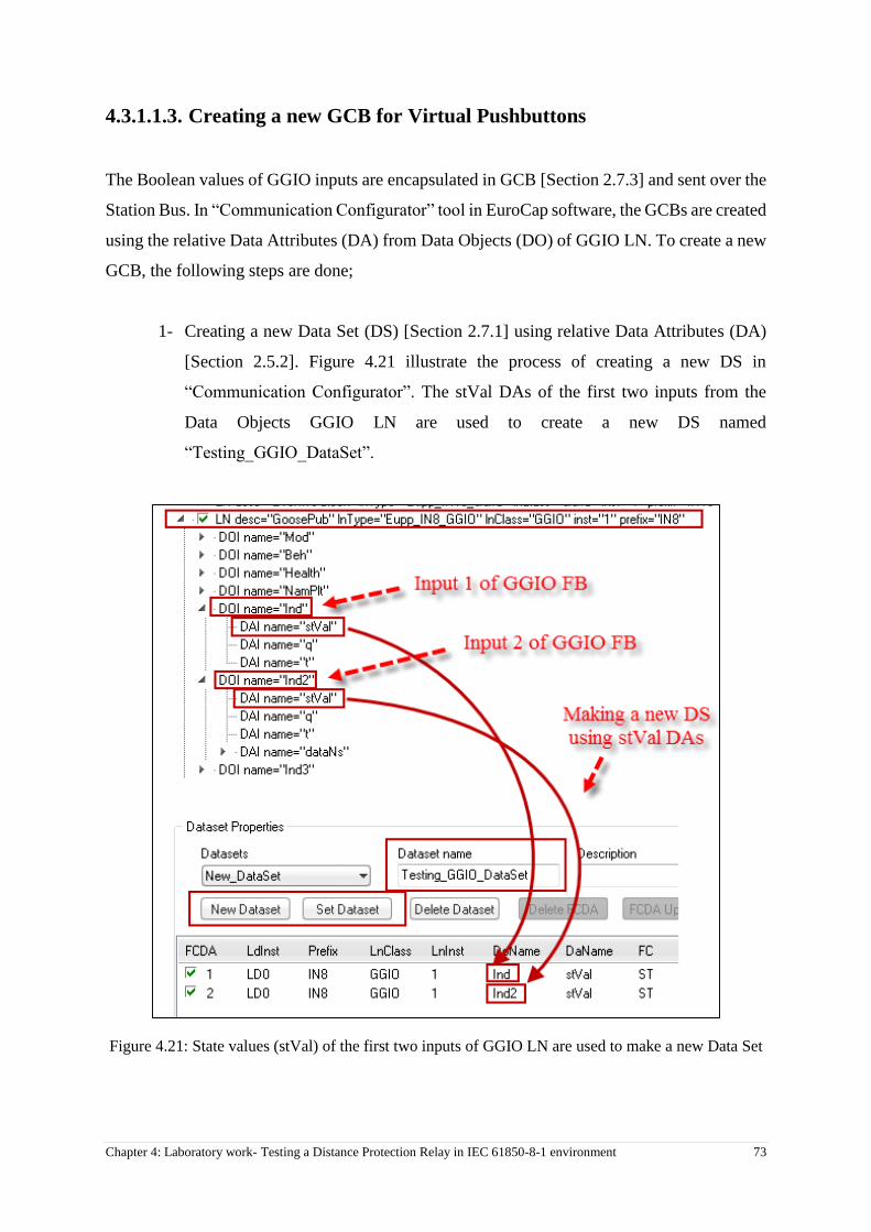
Chapter 4: Laboratory work- Testing a Distance Protection Relay in IEC 61850-8-1 environment 73
4.3.1.1.3. Creating a new GCB for Virtual Pushbuttons
The Boolean values of GGIO inputs are encapsulated in GCB [Section 2.7.3] and sent over the
Station Bus. In “Communication Configurator” tool in EuroCap software, the GCBs are created
using the relative Data Attributes (DA) from Data Objects (DO) of GGIO LN. To create a new
GCB, the following steps are done;
1- Creating a new Data Set (DS) [Section 2.7.1] using relative Data Attributes (DA)
[Section 2.5.2]. Figure 4.21 illustrate the process of creating a new DS in
“Communication Configurator”. The stVal DAs of the first two inputs from the
Data Objects GGIO LN are used to create a new DS named
“Testing_GGIO_DataSet”.
Figure 4.21: State values (stVal) of the first two inputs of GGIO LN are used to make a new Data Set
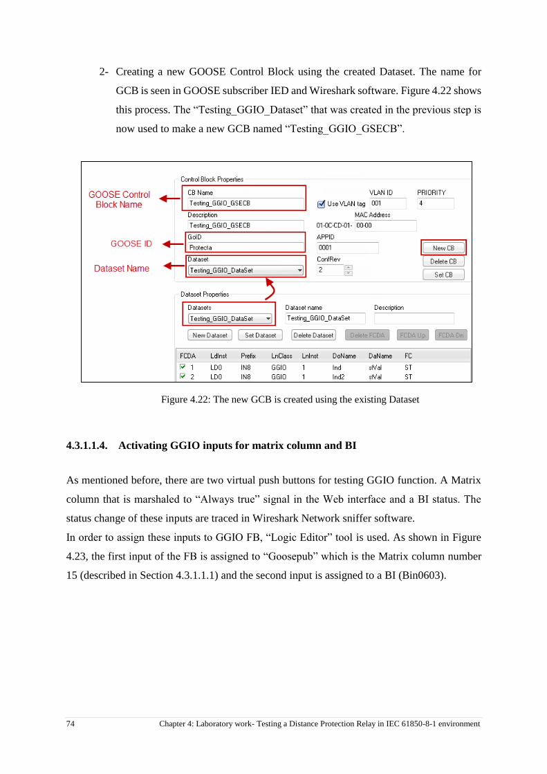
74 Chapter 4: Laboratory work- Testing a Distance Protection Relay in IEC 61850-8-1 environment
2- Creating a new GOOSE Control Block using the created Dataset. The name for
GCB is seen in GOOSE subscriber IED and Wireshark software. Figure 4.22 shows
this process. The “Testing_GGIO_Dataset” that was created in the previous step is
now used to make a new GCB named “Testing_GGIO_GSECB”.
Figure 4.22: The new GCB is created using the existing Dataset
4.3.1.1.4. Activating GGIO inputs for matrix column and BI
As mentioned before, there are two virtual push buttons for testing GGIO function. A Matrix
column that is marshaled to “Always true” signal in the Web interface and a BI status. The
status change of these inputs are traced in Wireshark Network sniffer software.
In order to assign these inputs to GGIO FB, “Logic Editor” tool is used. As shown in Figure
4.23, the first input of the FB is assigned to “Goosepub” which is the Matrix column number
15 (described in Section 4.3.1.1.1) and the second input is assigned to a BI (Bin0603).
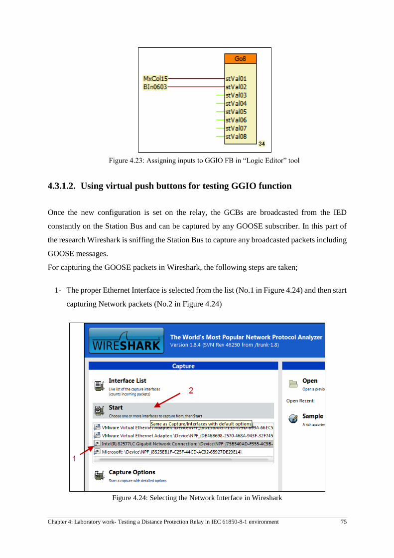
Chapter 4: Laboratory work- Testing a Distance Protection Relay in IEC 61850-8-1 environment 75
Figure 4.23: Assigning inputs to GGIO FB in “Logic Editor” tool
4.3.1.2. Using virtual push buttons for testing GGIO function
Once the new configuration is set on the relay, the GCBs are broadcasted from the IED
constantly on the Station Bus and can be captured by any GOOSE subscriber. In this part of
the research Wireshark is sniffing the Station Bus to capture any broadcasted packets including
GOOSE messages.
For capturing the GOOSE packets in Wireshark, the following steps are taken;
1- The proper Ethernet Interface is selected from the list (No.1 in Figure 4.24) and then start
capturing Network packets (No.2 in Figure 4.24)
Figure 4.24: Selecting the Network Interface in Wireshark

76 Chapter 4: Laboratory work- Testing a Distance Protection Relay in IEC 61850-8-1 environment
2- Wireshark starts capturing all types of Network protocols including GOOSE. GOOSE
messages are highlighted in Figure 4.25.
Figure 4.25: Different types of Network packets are captured by Wireshark
3- “GOOSE filter” is selected in Wireshark, so only the GOOSE packets will be shown in
the Capture window (Figures 4.26 and 4.27).
Figure 4.26: Applying GOOSE filter expression in Wireshark

Chapter 4: Laboratory work- Testing a Distance Protection Relay in IEC 61850-8-1 environment 77
Figure 4.27: Only the GOOSE packets are shown when the GOOSE filter is applied
4- The default state values of the GGIO Inputs are “0”. Once receiving the GOOSE
messages in Wireshark, the contents of them are analyzed. As shown in Figure 4.28 the
name, ID and Boolean contents of each GCB is compared to relay setting in Wireshark.
If there is more than one IED, these names will be critical to designate the source of the
GOOSE messages.
Figure 4.28: Boolean Values of the GGIO inputs are “0 or False” in the received GOOSE
message

78 Chapter 4: Laboratory work- Testing a Distance Protection Relay in IEC 61850-8-1 environment
5- To check the status changes in the arrived GOOSE messages, the status of GGIO inputs
are changed using the Relay Web interface. The following steps are taken.
a. The Matrix column “GoosePub” is assigned to an “Always true” row to change the
Boolean value of related DA of the first GGIO input (Figure 4.29). The “Always
True” row and “GoosePub” column are created in Sections 4.3.1.1.1 and 4.3.1.1.2.
Figure 4.29: Matrix tool in Relay web interface is used to change the status of first input GGIO FB
b. The GCB is checked again in Wireshark to see the change of the first input of GGIO
FB from “False” to “True”. (Figure 4.30).
Figure 4.30: StVal of the first input of GGIO has been changed from “0” to “1 or True”
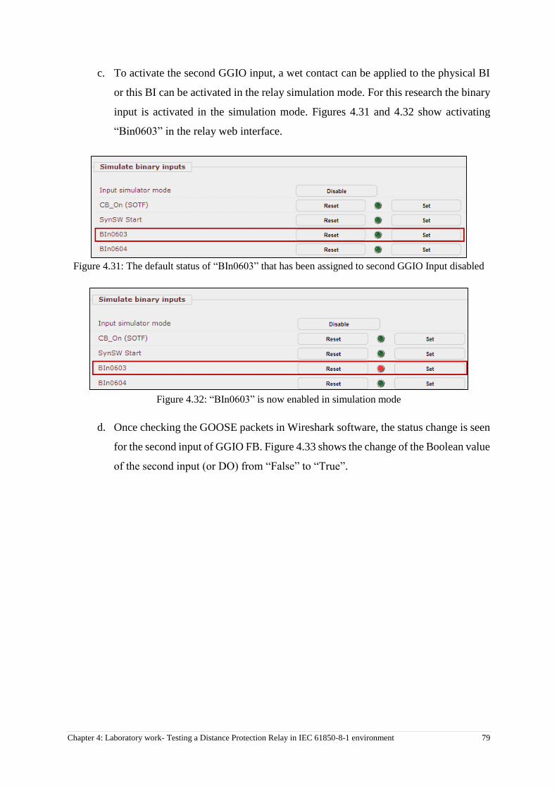
Chapter 4: Laboratory work- Testing a Distance Protection Relay in IEC 61850-8-1 environment 79
c. To activate the second GGIO input, a wet contact can be applied to the physical BI
or this BI can be activated in the relay simulation mode. For this research the binary
input is activated in the simulation mode. Figures 4.31 and 4.32 show activating
“Bin0603” in the relay web interface.
Figure 4.31: The default status of “BIn0603” that has been assigned to second GGIO Input disabled
Figure 4.32: “BIn0603” is now enabled in simulation mode
d. Once checking the GOOSE packets in Wireshark software, the status change is seen
for the second input of GGIO FB. Figure 4.33 shows the change of the Boolean value
of the second input (or DO) from “False” to “True”.

80 Chapter 4: Laboratory work- Testing a Distance Protection Relay in IEC 61850-8-1 environment
Figure 4.33: “StVal” of the second input of GGIO has now been changed from “0” to “1 or True”
This test proves that the GOOSE publisher IED (EuroProt+ relay) is broadcasting the GOOSE
messages correctly on the Station Bus as the GOOSE subscriber (Wireshark) sees the changes
in the state values of DAs in the approved manner.
4.3.2. Testing Distance protection function using virtual trips
The concentration of this research is not on the details of Distance protection testing but is to
prove that virtual trip signals are travelling correctly over the Station Bus. This test can be
expanded to any other protection relay testing such as Differential and Over Current.
The first step of the final test is the preparation of software and hardware tools to make them
ready to work in the station level of IEC61850 environment. The process of setting the
EuroProt+ relay, DRTS66 test set and Wireshark software have been discussed in Section 4.2
in details.
Now, the “Distance21” program in TDMS software has been configured for a 4 zone distance
protection scheme which came through a RIO file from the EuroProt+ relay [Section 4.2.2].
The EuroProt+ relay has been configured to send the trip commands through GOOSE messages
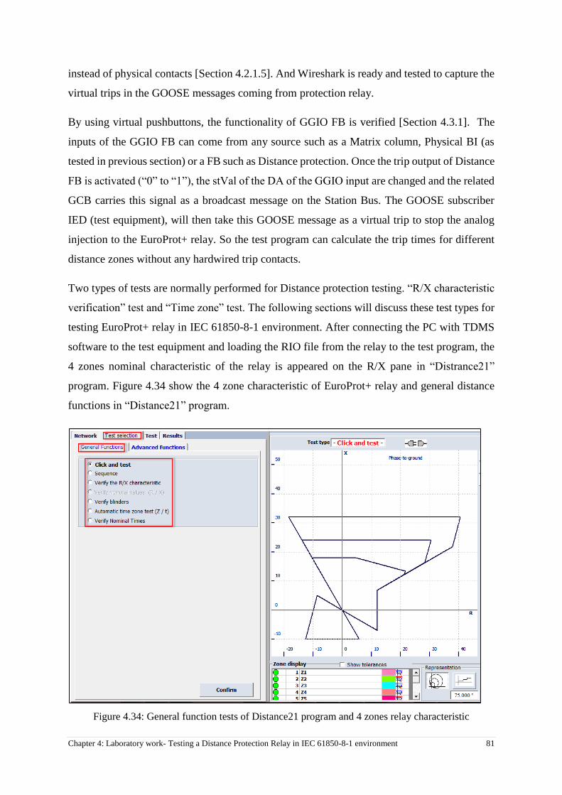
Chapter 4: Laboratory work- Testing a Distance Protection Relay in IEC 61850-8-1 environment 81
instead of physical contacts [Section 4.2.1.5]. And Wireshark is ready and tested to capture the
virtual trips in the GOOSE messages coming from protection relay.
By using virtual pushbuttons, the functionality of GGIO FB is verified [Section 4.3.1]. The
inputs of the GGIO FB can come from any source such as a Matrix column, Physical BI (as
tested in previous section) or a FB such as Distance protection. Once the trip output of Distance
FB is activated (“0” to “1”), the stVal of the DA of the GGIO input are changed and the related
GCB carries this signal as a broadcast message on the Station Bus. The GOOSE subscriber
IED (test equipment), will then take this GOOSE message as a virtual trip to stop the analog
injection to the EuroProt+ relay. So the test program can calculate the trip times for different
distance zones without any hardwired trip contacts.
Two types of tests are normally performed for Distance protection testing. “R/X characteristic
verification” test and “Time zone” test. The following sections will discuss these test types for
testing EuroProt+ relay in IEC 61850-8-1 environment. After connecting the PC with TDMS
software to the test equipment and loading the RIO file from the relay to the test program, the
4 zones nominal characteristic of the relay is appeared on the R/X pane in “Distrance21”
program. Figure 4.34 show the 4 zone characteristic of EuroProt+ relay and general distance
functions in “Distance21” program.
Figure 4.34: General function tests of Distance21 program and 4 zones relay characteristic

82 Chapter 4: Laboratory work- Testing a Distance Protection Relay in IEC 61850-8-1 environment
4.3.2.1. Virtual contact configuration in TDMS software
In order to test a conventional protection relay, the physical contacts output of the relay are
connected to the test equipment’s binary inputs (BI). So whenever the relay issues a trip
command, it goes to a BI of the test set to stop injection and testing software calculates the trip
times and other parameters. In order to stop injection in an IEC 61850-8-1 environment, the
GOOSE messages (virtual contacts) are used instead of the physical BIs of the test set. So the
test set must be equipped with a dedicated hardware and software to handle GOOSE messages
to stop the analog injection. Figure 4.35 illustrates the physical BIs and IEC 61850-8-1
hardware interface of the DRTS66 test set.
Figure 4.35: Using IEC 61850-8-1 interface instead of conventional BIs for relay trip contacts
Virtual contacts are set through an embedded program in “Distance21” which is called “Goose
Explorer”. This program is to capture the GOOSE messages on the Station Bus and link them
the main testing program. Figure 4.36 shows how to access IEC 61850-8-1 software interface
to setup the virtual inputs for distance testing.

Chapter 4: Laboratory work- Testing a Distance Protection Relay in IEC 61850-8-1 environment 83
Figure 4.36: Setting BIs for distance testing (conventional and non-conventional digital
inputs)
Once the “Goose Explorer” program is opened, the station bus is explored to capture any
GOOSE messages broadcasting on the network. Figure 4.37 shows the “Goose Explorer”
software interface inside the “Distace21” program. As the first step, this program sniffs the
station bus to capture all GOOSE messages transferring on the network.
Figure 4.37: “Goose Explorer” program is ready to sniff the Station Bus for GOOSE messages
The program sniffs the Station Bus for 30 sec (configurable) and shows a list of broadcasted
GOOSE messages on the network. In the list of captured GOOSE messages, the proper Goose
Control Block (GCB) is selected and used as virtual input for the test set. To determine the
correct GCB, “Goose Explorer” provides different options. A GCB can be chosen based on the
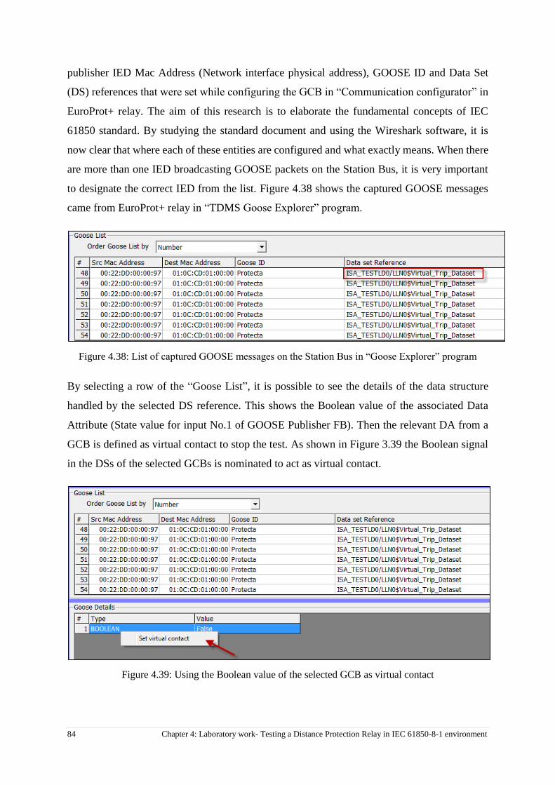
84 Chapter 4: Laboratory work- Testing a Distance Protection Relay in IEC 61850-8-1 environment
publisher IED Mac Address (Network interface physical address), GOOSE ID and Data Set
(DS) references that were set while configuring the GCB in “Communication configurator” in
EuroProt+ relay. The aim of this research is to elaborate the fundamental concepts of IEC
61850 standard. By studying the standard document and using the Wireshark software, it is
now clear that where each of these entities are configured and what exactly means. When there
are more than one IED broadcasting GOOSE packets on the Station Bus, it is very important
to designate the correct IED from the list. Figure 4.38 shows the captured GOOSE messages
came from EuroProt+ relay in “TDMS Goose Explorer” program.
Figure 4.38: List of captured GOOSE messages on the Station Bus in “Goose Explorer” program
By selecting a row of the “Goose List”, it is possible to see the details of the data structure
handled by the selected DS reference. This shows the Boolean value of the associated Data
Attribute (State value for input No.1 of GOOSE Publisher FB). Then the relevant DA from a
GCB is defined as virtual contact to stop the test. As shown in Figure 3.39 the Boolean signal
in the DSs of the selected GCBs is nominated to act as virtual contact.
Figure 4.39: Using the Boolean value of the selected GCB as virtual contact
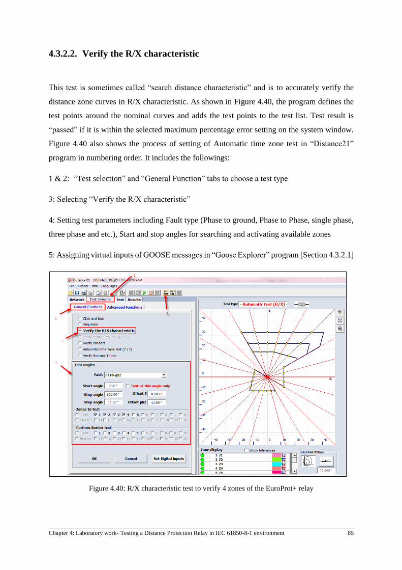
Chapter 4: Laboratory work- Testing a Distance Protection Relay in IEC 61850-8-1 environment 85
4.3.2.2. Verify the R/X characteristic
This test is sometimes called “search distance characteristic” and is to accurately verify the
distance zone curves in R/X characteristic. As shown in Figure 4.40, the program defines the
test points around the nominal curves and adds the test points to the test list. Test result is
“passed” if it is within the selected maximum percentage error setting on the system window.
Figure 4.40 also shows the process of setting of Automatic time zone test in “Distance21”
program in numbering order. It includes the followings:
1 & 2: “Test selection” and “General Function” tabs to choose a test type
3: Selecting “Verify the R/X characteristic”
4: Setting test parameters including Fault type (Phase to ground, Phase to Phase, single phase,
three phase and etc.), Start and stop angles for searching and activating available zones
5: Assigning virtual inputs of GOOSE messages in “Goose Explorer” program [Section 4.3.2.1]
Figure 4.40: R/X characteristic test to verify 4 zones of the EuroProt+ relay
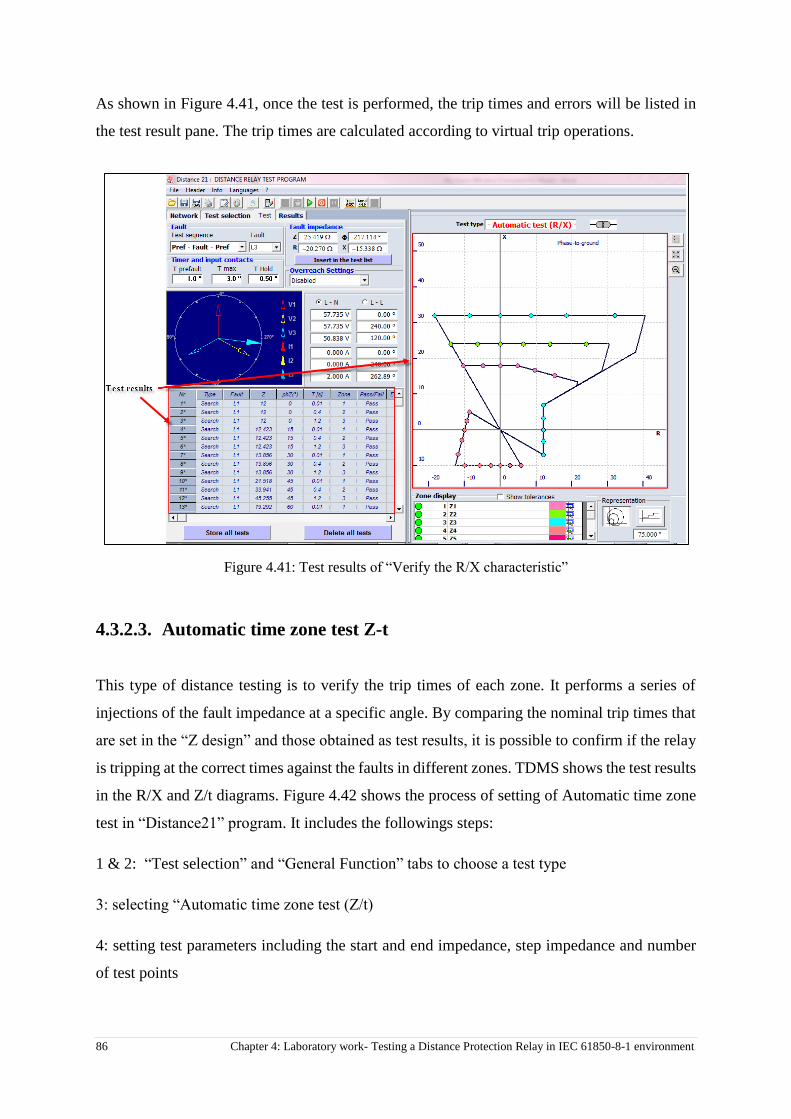
86 Chapter 4: Laboratory work- Testing a Distance Protection Relay in IEC 61850-8-1 environment
As shown in Figure 4.41, once the test is performed, the trip times and errors will be listed in
the test result pane. The trip times are calculated according to virtual trip operations.
Figure 4.41: Test results of “Verify the R/X characteristic”
4.3.2.3. Automatic time zone test Z-t
This type of distance testing is to verify the trip times of each zone. It performs a series of
injections of the fault impedance at a specific angle. By comparing the nominal trip times that
are set in the “Z design” and those obtained as test results, it is possible to confirm if the relay
is tripping at the correct times against the faults in different zones. TDMS shows the test results
in the R/X and Z/t diagrams. Figure 4.42 shows the process of setting of Automatic time zone
test in “Distance21” program. It includes the followings steps:
1 & 2: “Test selection” and “General Function” tabs to choose a test type
3: selecting “Automatic time zone test (Z/t)
4: setting test parameters including the start and end impedance, step impedance and number
of test points
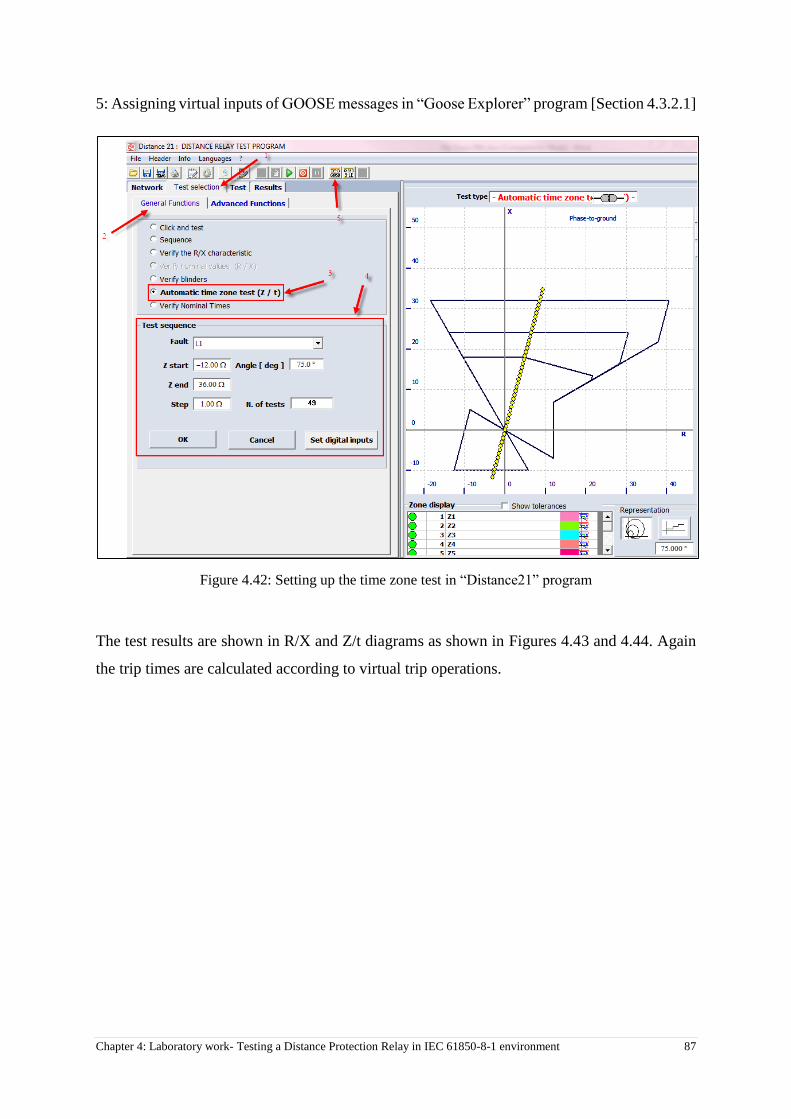
Chapter 4: Laboratory work- Testing a Distance Protection Relay in IEC 61850-8-1 environment 87
5: Assigning virtual inputs of GOOSE messages in “Goose Explorer” program [Section 4.3.2.1]
Figure 4.42: Setting up the time zone test in “Distance21” program
The test results are shown in R/X and Z/t diagrams as shown in Figures 4.43 and 4.44. Again
the trip times are calculated according to virtual trip operations.
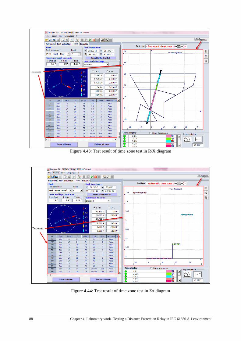
88 Chapter 4: Laboratory work- Testing a Distance Protection Relay in IEC 61850-8-1 environment
Figure 4.43: Test result of time zone test in R/X diagram
Figure 4.44: Test result of time zone test in Z/t diagram

Chapter 4: Laboratory work- Testing a Distance Protection Relay in IEC 61850-8-1 environment 89
4.3.2.4. Wireshark analysis
The contents of the GOOSE messages sent by GGIO FB in EuroProt+ relay were analyzed in
Section 4.3.1.2 for virtual push buttons. There is no difference as to what is producing the
virtual signal whether it is because of operation of Virtual push buttons or a protection FB
output. Once the input status of GGIO LN is changed (i.e. from False to True), the DA Boolean
value in GCB will be changed. The same practice is done for testing the virtual trips for distance
protection as virtual pushbuttons [Section 4.3.2.4]. Since there are about 100 test points in the
automatic test program, two sampled GOOSE messages of the virtual contacts captured by
Wireshark are picked for content analysis.
Figure 4.45 and 4.46 illustrate the contents of two GOOSE message captured by Wireshark
during the secondary injection to the relay for distance testing. Once the distance FB issues the
trip, the first input of GGIO FB is activated. This, then changes the state of Boolean value of
the related Data attribute in the GCB. This is the signal that causes the test set to stop injection
for each test point. The Wireshark analysis demonstrates the GCB name, ID and Data Set name
that were used in the relay. The Boolean value of the arrived packet is also shown in Figure
4.45 and 4.46 and the status change confirms that the protection function is operating well and
GOOSE signals are acting exactly as expected to replace the conventional hardwiring.
Figure 4.45: Boolean Value of the GGIO input 1 is “0 or False” in the received GOOSE message for “Virtual
Trip” DS

90 Chapter 4: Laboratory work- Testing a Distance Protection Relay in IEC 61850-8-1 environment
Figure 4.46: Boolean Value of the GGIO input 1 is “1 or True” in the received GOOSE message for “Virtual
Trip” DS
Conclusion
In this chapter the laboratory work for testing distance protection function of a 61850-
compatible relay is explained step by step. The main concepts of the station level related
applications of IEC 61850 that were explained in Chapter 2 are used in a practical work of
testing the relay to integrate the theory into the practice. Wireshark software is used to analyze
the GOOSE packets transferring between the relay and test equipment and shows the
encapsulated information into the GOOSE massages. Virtual push button is a new method that
is suggested in this chapter to test any protection FB in the relay without using the non-
conventional test equipment and by only using an open source third party application. This
method confirms the proper operation of protection FBs, IEC 61850 I/O FB and Station Bus
before using any testing tools. It also helps testing Engineers/ technicians to have a better
understanding of what is happening in the backstage of the relay and test set software tools.
Finally, the distance protection testing was carried out and the station bus were analyzed in
Wireshark to check the GOOSE packets that actually tripped the test set to stop analog
injection.

Chapter 5: Conclusion 91
Chapter 5: Conclusion
5.1 Summary
IEC 61850 is the new global standard for communications in substations. The standard seems
to be here to stay, since it covers all aspects of substation automation and is future-proof.
However, every new technology brings its own complexity together with improving the
existing systems. The primary aim of this research was to gain a greater understanding of how
the IEDs communicate to each other on the station level in a substation automation system
(SAS). This was achieved through a testing practice of a native IEC 61850 protection relay and
a non-conventional test equipment. By using a third party network analyzer software, the
GOOSE messages transferring on the station level were captured and analyzed to give a better
understanding of what is going on in the backstage of the IEDs in an automated substation.
From now on, utilities need to have sufficient knowledge of how IEC 61850 protection systems
operate as it is essential for ongoing maintenance of the substations. Testing the non-
conventional protection relays is still a challenge for testing Engineers /technicians as there is
not enough knowledge in this field. As IEC 61850 has introduced the new concepts in electrical
substations, there might not be any more hardwires in the protection panels and so the signals
cannot be checked visually to make sure that they are linked to the correct IEDs. The testing
personnel only work with the relay, test equipment and the software programs without knowing
what is exactly happening to the signals in the background. This would be very dangerous as
any wrong selection in relay or testing programs might cause a wrong circuit breaker operation
or relay is not commissioned properly.
In this research study the contents of the GOOSE packets of the virtual trips are expanded in a
third party software to elaborate the parameters that the end-user sees in the relay and test
programs. Virtual pushbutton was a new concept that was proposed in this research and helped
to test the GCBs [Section 2.7.3] and changing the Boolean values of the data attributes (DAs).
This provides a virtual way to test signals on the station level that used to be tested by
Multimeter’s continuity check! Finally, each part of the configuration software tools in the
relay and test set is referred to the related standard document.
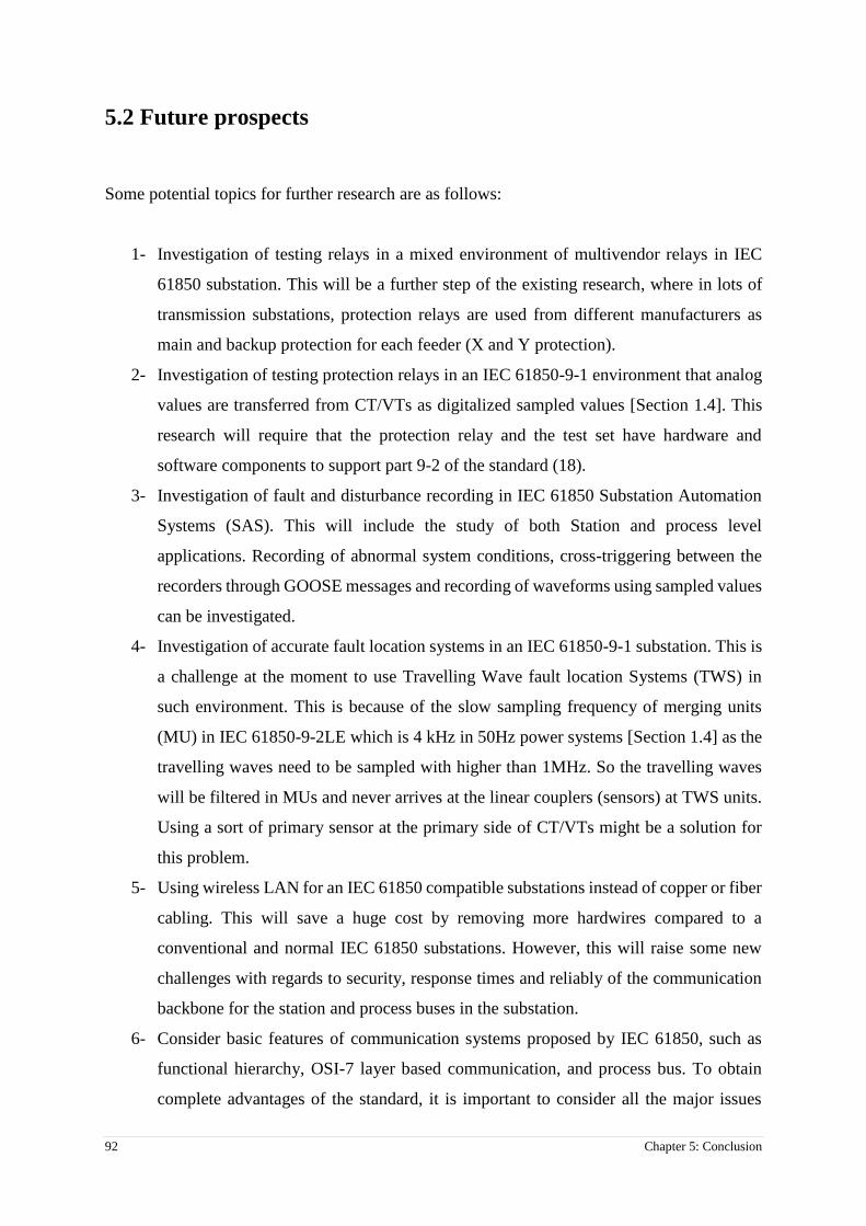
92 Chapter 5: Conclusion
5.2 Future prospects
Some potential topics for further research are as follows:
1- Investigation of testing relays in a mixed environment of multivendor relays in IEC
61850 substation. This will be a further step of the existing research, where in lots of
transmission substations, protection relays are used from different manufacturers as
main and backup protection for each feeder (X and Y protection).
2- Investigation of testing protection relays in an IEC 61850-9-1 environment that analog
values are transferred from CT/VTs as digitalized sampled values [Section 1.4]. This
research will require that the protection relay and the test set have hardware and
software components to support part 9-2 of the standard (18).
3- Investigation of fault and disturbance recording in IEC 61850 Substation Automation
Systems (SAS). This will include the study of both Station and process level
applications. Recording of abnormal system conditions, cross-triggering between the
recorders through GOOSE messages and recording of waveforms using sampled values
can be investigated.
4- Investigation of accurate fault location systems in an IEC 61850-9-1 substation. This is
a challenge at the moment to use Travelling Wave fault location Systems (TWS) in
such environment. This is because of the slow sampling frequency of merging units
(MU) in IEC 61850-9-2LE which is 4 kHz in 50Hz power systems [Section 1.4] as the
travelling waves need to be sampled with higher than 1MHz. So the travelling waves
will be filtered in MUs and never arrives at the linear couplers (sensors) at TWS units.
Using a sort of primary sensor at the primary side of CT/VTs might be a solution for
this problem.
5- Using wireless LAN for an IEC 61850 compatible substations instead of copper or fiber
cabling. This will save a huge cost by removing more hardwires compared to a
conventional and normal IEC 61850 substations. However, this will raise some new
challenges with regards to security, response times and reliably of the communication
backbone for the station and process buses in the substation.
6- Consider basic features of communication systems proposed by IEC 61850, such as
functional hierarchy, OSI-7 layer based communication, and process bus. To obtain
complete advantages of the standard, it is important to consider all the major issues

Chapter 5: Conclusion 93
related to practical implementation. The challenge is to implement new communication
architecture, such as process bus and station bus. Further, the overall substation
functional and planning issues some possible solutions to several major implementation
need to be investigated.
7- In order to implement an IEC 61850 communication system, there needs to be a
complete understanding of the methods, tools and technologies associated with the
communication network, protocol and messaging underpinning the services. The IEC
61850 standard allows for communication between devices within a substation where
a peer-to-peer model for Generic Substation Events (GSE) services is used for fast and
reliable communication between IEDs. One of the messages associated with the GSE
services is the Generic Object Oriented Substation Event (GOOSE) message. A detailed
analysis of the structure for the GOOSE message is required for fault diagnosis, or when
developing hardware that is compliant with the IEC 61850 standard. This is one of the
stated objectives of the Centre for Substation Automation and Energy Management
Systems (CSAEMS) in the training of prospective specialists and engineers. A case
study can then be presented where the structure of the GOOSE message as described in
IEC 61850-8-1 is confirmed using firstly simulation, then experimentation with actual
IEDs. In the first instance the message structure is confirmed by simulation of the
GOOSE message and capturing it using network protocol analyser software, after
which analysis of the packet frame is performed. Data encoding of the GOOSE Protocol
Data Unit (PDU) can be analysed with emphasis on the Abstract Syntax Notation (ASN.
1) Basic Encoding Rules (BER). The second part of the case study is conducted through
experimentation with IEDs which are used to generate a GOOSE message and network
protocol analyser software is used to analyse the structure. Both the simulation and
practical experimentation with actual devices can be shown to confirm to the GOOSE
message structure as specified in part 8-1 of the IEC 61850 standard.
8- For the last few years we have been facing a strong trend towards new technologies and
standards. The most significant task is to fundamentally transform the capabilities and
bring new solutions that support better power quality supply. Standardization solution
IEC 61850 in terms of protection, monitoring and control functions is a promising
solution that provides a great impact on substation automation based on increasing the
reliability and availability of the electric power grid. Communication in substation
based on the IEC61850 standard that specifies Ethernet network for substation
automation which provides an efficient performance. This efficiency has been
94 Chapter 5: Conclusion
introduced by means of high flexibility of configuring various architectures based on
implementing Ethernet switches. One of the future work can be to realistically
investigate the reliability and availability for substation protection function based on
Reliability Block Diagram (RBD) approach for practical substation architecture in
different configuration.
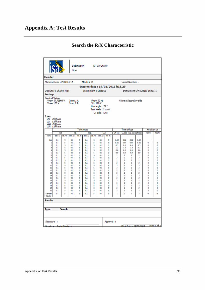
Appendix A: Test Results 95
Appendix A: Test Results
Search the R/X Characteristic

96 Appendix A: Test Results

Appendix A: Test Results 97
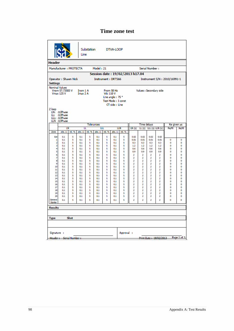
98 Appendix A: Test Results
Time zone test

Appendix A: Test Results 99

100 Appendix A: Test Results

References 101
References
[1] T. Maeda," A testing environment", ABB Review, Special Report IEC 61850; 2010. p. 29-
32.
[2] Lundqvist, B., 100 years of relay protection, the Swedish ABB relay history,".
Sweden.[Online], 2010.
[3] Rao, T.M., Power system protection: static relays. 1989.
[4] Johns, A.T. and S.K. Salman, Digital protection for power systems. 1997.
[5] IEC 61850-8-1 Ed. 2 FDIS: Communication networks and systems for power utility
automation Part 8- 1: Specific communication service mapping (SCSM) – Mapping to MMS
(ISO 9506-1 and ISO 9506-2) and to ISO/IEC 8802-3; 2010.
[6] Hintikka, J., T. Runtti, and M. Puurunen, KEDI-project: Creating the Automation
Architecture with the Common Fieldbus Diagnostic Tool. Electrónica e Telecomunicações,
2013. 3(1): p. 51-53.
[7] Brand, K., C. Brunner, and W. Wimmer, Design of IEC 61850 based substation
automation systems according to customer requirements. Indian Journal of Power and River
Valley Development, 2011. 61(5): p. 87.
[8] Proudfoot, D., UCA and 61850 for Dummies. Siemens Power Transmission and
Distribution, 2002: p. 21-03.
[9] Apostolov, A. IEC 61850 and Power-quality Monitoring and Recording. in Power
Quality. 2007. Springer London.
[10] IEC 61850 standard from http://en.wikipedia.org/wiki/IEC_61850
[11] Hossenlopp, L., Engineering perspectives on IEC 61850. Power and Energy Magazine,
IEEE, 2007. 5(3): p. 45-50.
[12] Mackiewicz, R. Overview of IEC 61850 and Benefits. in Power Systems Conference and
Exposition, 2006. PSCE'06. 2006 IEEE PES. 2006. IEEE.
[13] Brunner, C. IEC 61850 for power system communication. in Transmission and
Distribution Conference and Exposition, 2008. T&# x00026; D. IEEE/PES. 2008. IEEE.
[14] Brand, K.-P., The introduction of IEC 61850 and its impact on protection and
automation within substations. ELECTRA-CIGRÉ, 2007. 233: p. 21-29.
[15] IEC 61850-1: Communication Networks and Systems in Substations; Introduction and
Overview; 2003.
[16] Kim, G.-S. and H.-H. Lee. A study on IEC 61850 based communication for intelligent
electronic devices. in Science and Technology, 2005. KORUS 2005. Proceedings. The 9th
Russian-Korean International Symposium on. 2005. IEEE.

102 References
[17] Brunner, C., The impact of IEC 61850 on protection. 2008.
[18] IEC. IEC61850-9-2: Specific communication service mapping (SCSM) – Mapping on an
IEEE 802.3 based process.
[19] Janssen, M. and A. Apostolov. IEC 61850 impact on substation design. in Transmission
and Distribution Conference and Exposition, 2008. T&# x00026; D. IEEE/PES. 2008. IEEE.
[20] Apostolov, A. and B. Vandiver. Testing requirements for IEC 61850 based devices. in
Power Systems Conference: Advanced Metering, Protection, Control, Communication, and
Distributed Resources, 2007. PSC 2007. 2007. IEEE.
[21] IEC 61850-7-2: Communication Networks and Systems in Substations, Part 7-2: Basic
Communication structure for substations and feeder equipment
[22] IEC 61850-7-3: Communication Networks and Systems in Substations, Part 7-3: Basic
Communication structure for substations and feeder equipment – Common data classes
[23] IEC 61850-7-4 Ed.2 FDIS: 2010 Communication networks and system for power utility
automation – part 7-4 Basic communication structure – Compatible logical node classes and
data object classes
[24] Kezunovi, M., T. Djoki, and T. Kosti. Automated monitoring and control using new data
integration paradigm. in System Sciences, 2005. HICSS'05. Proceedings of the 38th Annual
Hawaii International Conference on. 2005. IEEE.
[25] Baigent, D., et al. IEC 61850 communication networks and systems in substations: an
overview for users. in Proceedings of the VIII simposio iberoamericano sobre proteccion de
sistemas electricos de potencia, Monterey, Mexico, Citeseer. 2004.
[26] Brand, K.-P., et al., Requirements of interoperable distributed functions and
architectures in IEC 61850-based SA systems. Proc. CIGRE, 2006.
[27] IEC. IEC61850-9-1: Specific communication service mapping (SCSM) - Serial
Unidirectional multidrop point to point link.
[28] Liang, Y. and R.H. Campbell, Understanding and simulating the IEC 61850 standard.
2008.
[29] IEC 61850-6 Ed. 2: Communication networks and systems for power utility automation
– Part 6: Configuration description language for communication in electrical substations
related to IEDs.
[30] IEC 61850-5: Communication Networks and Systems in Substations, Part 5:
Communication Requirements for Functions and Device Models.
[31] EuroProt+ product introduction from Protecta Website: http://protecta.hu/?oid=35
[32] EuroProt+ Distance protection function description from: http://protecta.hu/epp-
english/Function_blocks/Short/Short_04_Distance_protection_function.pdf
[33] IEEE C37.2: IEEE Standard for Electrical Power System Device Function Numbers,
Acronyms, and Contact Designations.
References 103
[34] EuroProt+ Hardware Description from: http://protecta.hu/epp-
english/HW_guide/hw_description_V1.36.pdf
[35] EuroProt+ Brochure from: http://protecta.hu/epp-english/Brochures/16oldalas_fuzet.pdf
[36] EuroProt+ Quick start Guide from: http://protecta.hu/epp-
english/QuickStart/Quick_Start_Guide_V1.0.pdf
[37] EuroCap configuration tool for EuroProt+ devices from: http://protecta.hu/epp-
english/SW_guide/EuroCap_V2.1.pdf
[38] DRTS 66 brochure from: http://www.isatest.com/index.php?page=drts-66
[39] Wireshark software from: http://en.wikipedia.org/wiki/Wireshark
[40] IEEE 802.1Q™: IEEE Standard for Local and metropolitan area networks--Media
Access Control (MAC) Bridges and Virtual Bridged Local Area Networks- orrigendum 2:
Technical and editorial corrections, 2011.
[41] IEC 60870-5-103: Telecontrol equipment and systems. Transmission protocols –
Companion standard for the informative interface of protection equipment, 1997.
[42] IEEE 1815- IEEE Standard for Electric Power Systems Communications -- Distributed
Network Protocol (DNP3), 2010.