shear resistance of reinforced concrete infilled frames · this research and hence the shear...
TRANSCRIPT

International Journal of Applied Science and Technology Vol. 2 No. 5; May 2012
148
Shear Resistance of Reinforced Concrete infilled Frames
T.C. Nwofor
Department of Civil and Environmental Engineering
University of Port Harcourt
P.M.B 5323 Port Harcourt
Rivers State, Nigeria.
Abstract
Reinforced concrete frames are usually infilled by masonry walls, but in most designs, the shear strength
response of these walls and also the contribution of the infill panel openings in the reduction of the shear strength of the infilled frame are ignored. In this work, two kinds of numerical models are used in order to validate the
finite element micro-modeling method and the basic stiffness method for macro-modeling of infilled frames. Also
full mechanical characterization of the brick-mortar units and masonry is also carried out through uniaxial compressive tests, where simple mechanical relationships at different confining stress levels are define with these
mechanical properties serving as the basic input parameter for the finite element micro-modeling method used in
this research and hence the shear response of infilled frames considering the effect of the sizes and position of
openings studied. The macro-modeling technique which analyses an equivalent one-strut model used to replace the infill panel gave results which were validated against that of the micro-modeling procedure. From the
foregoing both models will able to model the shear response of the frame up to a failure load. Finally the
procedure for macro-modeling used in this work is not computationally tedious and gives quick results, hence is recommended for non-linear analysis of infilled frame structures.
Keywords: Infill panel, Frames, Shear strength, modeling.
Introduction
Masonry is primarily used as infill in framed structures or load bearing members in unframed structures. The
brick wall is also in many circumstances subjected to lateral load, for instance wind and earthquake forces coming
upon the brick wall, especially in framed structures and also lateral earth pressure in tunnels and retaining walls. Also in a frame structure where the brick walls are seen to act as infill, they are subjected to little stiffening effects
which is a recent interest of researchers as regards design of framed structures.
This lateral loading of infilled frames has not received adequate attention especially when we consider the effect
of openings. Hence it is often neglected in the analysis by structural engineers. Such an assumption may lead to
substantial inaccuracy in predicting the lateral stiffness, strength and ductility of the frame. This feature of
masonry structure is our major interest in this investigation.
In order to achieve the set objectives this research work shall be aim at investigating the shear resistance of Brick-mortar masonry infilled reinforce concrete frame structure, considering size and position of openings in the infill.
The work shall make use of a suitable analytical methods such as the finite element and matrix stiffness methods
to analyze the micro and macro models of the structure for a plane stress problem. It is expected that the results
obtained would be validated when compared with previous test results conducted on one bay masonry infilled frame with central opening. An experimental procedure would also be carried out to determine the mechanical
properties for the analytical study. Suitable computer software formulated by the author would be employed to aid
this analysis because of the voluminous nature of the whole analytical procedure.
In other related works the behavior of masonry infilled frame structures has also been studied since the last
decades in attempts to develop a rational approach for design of such frames. It can be understood that if the
effect of infill is taken into account in the analysis and design of frame, the resulting structures may be significantly different [1] - [2].

© Centre for Promoting Ideas, USA www.ijastnet .com
149
Previous experimental research on the response of RC frames with masonry infill walls subject to static and
dynamic lateral cyclic loads [3]-[11] have shown that infill walls lead to significant increases in strength and stiffness in relation to bare RC frames. Considering conventional seismic design, which focuses on accelerations
and strength, it may be difficult to recognize the benefits of increases in stiffness. However, research and field
evidence [12]-[14] has shown that increases in stiffness are beneficial because they lead to reductions in the magnitude of the deformations induced by ground motions.
Even when it is a well known fact that infill walls have openings, recent research has concentrated on simple cases of infill wall without openings. Malick and Gorg [15] carried out an experimental investigation into the
effect of opening positions on the behaviour of infilled frames with or without shear connectors. It was observed
that opening at either end of the loaded diagonal of an infilled frame without connectors reduces its shear strength
by about 75% and it is compared to a similar infilled frame with solid panel. For infilled frame with shear connectors the reduction in shear strength was about 60-70% as compared with infilled frame with a solid panel.
The reduction of strength in both cases is as a result of the centrally loaded square opening.
The main purpose of this research is to model the shear strength resistance of lateral loaded infilled reinforced
concrete frame structure which accounts for the effect of sizes and position of openings in the infill panel using
the finite element method as an analytical tool and also to propose a nonlinear macro-model for lateral load analysis of masonry infilled reinforced concrete frame structure. We should note that in most cases, door and
window openings are provided in masonry infill panels to make up for functional and ventilation requirements of
buildings, hence considering these openings which are the true representation of masonry infilled structure adds complexity and difficulties in analysis. The presence of these openings would tend to reduce the lateral strength
and stiffness of the infilled frames. Hence the development of a suitable macro-model to predict the shear strength
response of masonry inflled frames with openings will be a necessary development.
Experimental Procedure
The properties of brickwork are influenced by variables of bricks, type of mortar, physical properties of the sand and lime used for the mortar, state of bricks before casting, curing workmanship and many others. Hence it can
be deduced that in the experimental determination of mechanical properties of brickwork, a large number of
variables can be considered. We should note that the analysis and design of buildings require the material properties of masonry, for example, the modulus of elasticity of masonry is require for the non-linear static
analysis. Stress-strain curves of masonry are required for more detailed non-linear analysis of masonry structures.
Hence, in this present study, extensive experimental testing of brick masonry prism material would be performed
to obtain its stress-strain curves. Also experimental relationships would be obtained its compressive strength. Furthermore, simple analytical equations are developed using the experimental data to estimate the mechanical
between the modulus of elasticity of masonry units of properties and plot the stress-strain curves for masonry.
However, to maintain the scope of this research, the materials used have been kept constant. The bricks, cement, sand and lime used are described below.
From the series of compressive strength tests, average relationships relating modulus of elasticity to compressive strength have been obtained for bricks and mortar as follows
b
E 345.10Fb (1)
Er = 231.11Fr (2)
Also average relationship have been obtained for masonry for cases of loadings perpendicular and parallel to the
bedding plane as follows in equations 3 and 4 respectively.
Em1 = 634.66Fm1 (3)
Em2 = 640.00Fm2 (4)
A study of the stress-strain curve, especially for the case of parallel loading shows that about four (4) salient
points are easily observed on the stress-strain prisms pattern. The strain values used to determine these points of
interest varying with the grade of mortar used in the prisms, as great difficulty is observed with deriving strain
values when a weak grade of mortar is used, especially after the near linear range; due to brick-mortar bond failure and inevitable sudden collapse of the test specimens. Hence four salient points indentified are follows:

International Journal of Applied Science and Technology Vol. 2 No. 5; May 2012
150
(a) point 0.40fm corresponding to the limit of the region at which the stress-strain curve is near linear as much as possible, after which regional cracks starts developing suggesting non-linearity.
(b) Point 0.75fm corresponding to the particular stress at which vertical splitting cracks are seen, but the
masonry specimen still remains relatively stable. (c) 0.95fm corresponds to the stress level of which the splitting cracks have reached a very advanced level and
failure is ready to occur.
(d) fm is the ultimate stress level in which the masonry is in a collapse state with a corresponding rapid
increase in strain reaching an observable failure strain in the masonry
Acknowledging that there exist a reasonable mathematical relationship between the compressive strength of
masonry and the modulus of elasticity of masonry, hence analytically modeling to obtain fm is necessary as it is not always very feasible to conduct test on masonry prisms. On the other hand, the compressive strength of brick
and mortar (Fb and Fr) can readily be obtained through tests. The compressive strengths of bricks, mortar and
masonry can be properly related as proposed by Eurocode [16] by equation 5
rbm fKff (5)
Where k, and are all constants for effective relationship. Observing the experimental stress-strain curves, fm
depends on the brick strength more than the mortar strength, hence must be higher than .
Conducting an unconstrained regression analysis on equation 5 using the data obtained from our experimental
study the values of 0.61, 0.51 and 0.36 have been obtained for k, and respectively, and the following equation proposed.
Fm = 0.6136.051.0
rb ff (6)
From the foregoing the basic mechanical properties of masonry has been obtained by tests carried out on
specimens. These mechanical properties are basic input parameters for the finite element micro-modeling of masonry infilled frame structure. Hence compressive test result obtained from test on brick units and mortar is
enough to predict the elastic properly of masonry, as simple relationships have been obtained for the modulus of
elasticity of bricks, mortar and masonry from their corresponding compressive strengths.
Numerical Method
The finite element method of analysis will be utilized for this work and it involves voluminous numerical works which will be considerably simplified by matrix formulation of the whole problem which is suitable for
computerization.
The basic concept of the finite element method of analysis is that the structure can be considered to be an assemblage of individual structural elements. Hence the idea of the finite element method is the use of two and
there dimensional elements for the idealization of a continuum, where accuracy of the solution increases with the
number of elements taken. For the purpose of this masonry infilled reinforced concrete frame analysis, the formulation used will be the displacement approach. In using this method the nodal displacements are the basic
unknown, while the stresses and strains are assumed constant for each element. The basic approach is to obtain
the triangular element stiffness matrix for a plane stress problem is well documented. We will only present some
essential features in this work.
The element stiffness matrix [Ke] would be a 6 x 6 matrix for this plane elasticity triangle because there exist a
two degree of freedom (DOF) at each node of the triangular element hence the Nodal force vector [Fe] can be
related to the displacement vector in equation 7.
eee KF (7)
A suitable displacement function is chosen to define the displacement at any point in the element. This is simply
represented by two linear polynomials functions containing six unknown coefficients 621
,
representing the six degrees of freedom in the case of a plane triangular element.

© Centre for Promoting Ideas, USA www.ijastnet .com
151
yxv
yxu
654
321
(8)
For plane elasticity problems the [D] matrix which represent the contribution of modulus of elasticity E and
poisons ratio v can be expressed as
33
2221
1211
00
0
0
d
dd
dd
D (9)
where for plane stress problem
d11 = d22 = yxxyx vvE 1
d12 = d21 = yxxyyxx vvvE 1
d33 = yxy vE 12
The relationship between element stresses and the nodal displacements is obtained as
eBDyx , (10)
where matrix [B] contains constant linear dimensional values.
The statically equivalent nodal forces {Fe} related to the nodal displacements e and hence the element
stiffness matrix [Ke] can be obtained as
eTe voldBDBF (11)
Carrying out the integration and noting that d(vol) can be represented by the area of the triangle multiplied by constant thickness t
eTe tBDBF (12)
Hence the triangular element stiffness matrix [Ke] is represented by
tBDBKTe (13)
The explicit form for [Ke] is obtained in equation (14). The case of plane stress and plane strain can be obtained
by substituting for the dij‘s from equation (9). It is simpler in practice to perform the matrix multiplications of equation (14) numerically in the computer.

International Journal of Applied Science and Technology Vol. 2 No. 5; May 2012
152
(14)
To determine the element stresses from the element nodal displacements, the relationship in equation (10) is considered where
eBDyx ,
Where the stress-displacement matrix
[H] = [D] [B]
edHyx , (15)
For the case of plane elasticity, the product of [H] = [D] [B] is given explicitly in equation (16).
213312331333333323333
1222223122322322322
122213231232321
2
1][][
23 yydxxdyydtxxdyydd
xxdytytdxxdtyytdxxdyytd
xxt
dytytdxtxtdtyytdxxtdyytd
BD
xx
(16)
In the case of the plane stress and strain triangular element, it can be seen that the strain is constant throughout the element. Hence, this element is thus referred to as a constant strain triangle. For convenience also, it is usual to
plot the stresses at the centroid of the element.
Consideration of Size and position of Openings on the Shear Strength of Infilled Frame Structure
In order to investigate the effect of the size of openings on the lateral strength and stiffness of infilled, reinforced
concrete frames, a parametric study would be conducted using the finite element analysis on the infilled brick masonry. The effect of the opening size on the shear strength would be studied for values of parameters denoted
by and m which is defined as percentage of the opening area to the solid infill panel area and ratio of the infill panel strength with openings to that without openings respectively.

© Centre for Promoting Ideas, USA www.ijastnet .com
153
Hence a number of one-story one-bay infilled structure with varying size of opening would be analyzed using
finite element method aided by the suitable computer programme code. A typical structural micro model for the analysis is shown below (figure 1-3) with a 30kN horizontal load acting at the top corner of the infilled reinforced
concrete frame structure.
In order use a suitable mechanical property for masonry, full mechanical characterization have been carried out
and results shown in table 1.
Table 1: Material elastic properties
Moduli of elasticity Poisson‘s ratio
Material Ex (kN/m2) Ey (kN/m
2) Vxy Vyx
Concrete 2.9 x 10⁷
2.9 x 10⁷
0.20 0.20
Masonry 4.4 x 10⁶
7.41 x 10⁶
0.22 0.33
To conduct properly this investigation the central opening of a one-bay infilled structure shown in figure 2 is
varied, but with particular interest on opening ratio of 0-25%. The following structural models tagged M1P01-M1P05 would be considered with each model having a particular percentage opening in the infilled panel.
Figure 1: Infilled reinforced concrete frame structure under the action of a static horizontal load
Figure 2: Infilled reinforced concrete frame structure with central opening
2.5
3.0 0.3 0.3
0.3 30kN
2.4
3.0 0.3 0.3
0.3 30kN

International Journal of Applied Science and Technology Vol. 2 No. 5; May 2012
154
Figure 3: Triangularly meshed micro-model ready for finite element analysis
From the result of the finite element analysis the values of shear strength reduction factor m would be plotted
against the values of the percentage opening . Later a consideration would be made using the shear strength
factor m to stimulate the equivalent width of the compressed diagonal strut, for the macro-modeling of infilled frame structure.
By investigating the varying configuration of the positioning of openings in the previous models (M1P01-M1P05), the effect on the shear strength of infilled frame is thus studied for the following cases
(a) Opening position is underneath the compressed diagonal (b) Opening position is just on the compressed diagonal
(c) Opening position is above the compressed diagonal
Effect of “Soft stories” on Shear Strength of Multi-Storey Infilled Frames
Multi-storey infilled frames often have particular storey levels without infilled panels and this constitutes ‗soft
stories‘ on the multistory infilled frame structure and this appears to reduce the shear strength in that storey level
compared to the adjacent ones, hence this shifts the concentration of stresses to the carrying elements of the soft storey, leading to extensive damages in most cases. The most common case of soft storey in building frames
appears in the ground storey where in this case the stiffness of the ground storey appears drastically reduced due
to decrease of infill walls. The importance of this observation forms the basis of our advancing our investigation into the shear stress distribution along the columns of infilled frames. In carrying out this investigation, the
seismic behaviour of rigid multi-storey infilled frames, compared to that of multistory infilled frames with soft
storey or soft interim storey is considered. Again the finite element analytical modeling software developed
previously would be modified and used to aid this analysis. In this analysis, a 3-storey one-bay building frame of constant bay size subjected to lateral loads will be considered and analysis done. The lateral loads may represent
both wind and earthquake loads. The lateral wind load remains same at each storey level as the contact surface
remains the same. A study of the shear stress of the frames for a case of rigid frame and cases of soft storey effect would be undertaken. Figure 4 displays the cases considered in this investigation as follows:
(a) Type MIF 01: Rigid infilled frame (b) Type MIF02: Soft storey in ground floor of infilled frame
(c) Type MIF 03: Soft storey in second floor of infilled frame
(d) Type MIF 04: Bare frame
30kN
o o o

© Centre for Promoting Ideas, USA www.ijastnet .com
155
Figure 4: Infilled frame structure displaying four different cases of infilled frame structure considered.
Type MIF03 Type MIF04
Type MIF02 Type MIF01
International Journal of Applied Science and Technology Vol. 2 No. 5; May 2012
156
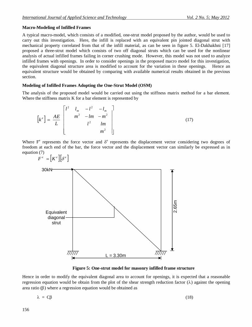
Macro-Modeling of Infilled Frames
A typical macro-model, which consists of a modified, one-strut model proposed by the author, would be used to
carry out this investigation. Here, the infill is replaced with an equivalent pin jointed diagonal strut with
mechanical property correlated from that of the infill material, as can be seen in figure 5. El-Dakhakhni [17] proposed a three-strut model which consists of two off diagonal struts which can be used for the nonlinear
analysis of actual infilled frames failing in corner crushing mode. However, this model was not used to analyze
infilled frames with openings. In order to consider openings in the proposed macro model for this investigation, the equivalent diagonal structure area is modified to account for the variation in these openings. Hence an
equivalent structure would be obtained by comparing with available numerical results obtained in the previous
section.
Modeling of Infilled Frames Adopting the One-Strut Model (OSM)
The analysis of the proposed model would be carried out using the stiffness matrix method for a bar element.
Where the stiffness matrix K for a bar element is represented by
2
2
22
22
m
lml
mlmm
llll
L
AEk
mm
e (17)
Where Fe represents the force vector and
e represents the displacement vector considering two degrees of
freedom at each end of the bar, the force vector and the displacement vector can similarly be expressed as in
equation (7)
eee KF
Figure 5: One-strut model for masonry infilled frame structure
Hence in order to modify the equivalent diagonal area to account for openings, it is expected that a reasonable
regression equation would be obtain from the plot of the shear strength reduction factor () against the opening
area ratio () where a regression equation would be obtained as
= C (18)
L = 3.30m
2.6
5m
Equivalent diagonal
strut
30kN

© Centre for Promoting Ideas, USA www.ijastnet .com
157
where C is a constant to be determined from the resulting regression equation, the modified equivalent diagonal
region area in the infilled frames with a central window opening would given by
Am = mAd (19)
Also carrying out this analysis it would be necessary to note the geometric properties of the diagonal struts are
functions of the length of contact between the wall and the column h and between the wall and beam L.
Hence assuming a beam on elastic foundation as proposed by [18, 19] for h and L,
4
2
4
2
tSinE
hlE
m
cf
h (20)
and
4
2
4
tSinE
hlE
m
bf
L (21)
Where Em, Ef = elastic moduli of the masonry wall and frame material respectively.
t, h, l = thickness, height and length of the infill wall, respectively.
lc, lb = moments of inertia of the column and the beam of the frame respectively.
= tan-1
L
h
Hendry [20] proposed the following equation to determine the equivalent or effective strut width, w, where the strut is assumed to be subject to a uniform stress
22
2
1
2hc
(22)
Once the geometric and material properties of the struts are calculated, the stiffness matrix method for bar
elements would be employed to determine the stiffness of the infilled frame, the internal forces and the
deflections. An analytical code formulated by the author would be used to aid the analysis of several macro-models for several cases of openings considered in this research.
Results and Discussion
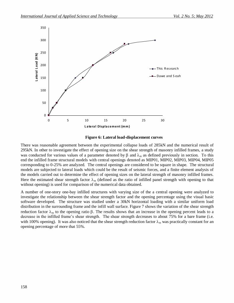
Stress path obtained from finite element analytical modeling of MIP04 model which is similar to the WC3 model conducted experimentally by [10] would be compared in other to validate this present analytical procedure for the
micro-modeling of masonry infilled concrete frame structure with openings as shown in figure 6.
International Journal of Applied Science and Technology Vol. 2 No. 5; May 2012
158
Figure 6: Lateral load-displacement curves
There was reasonable agreement between the experimental collapse loads of 285kN and the numerical result of
295kN. In other to investigate the effect of opening size on the shear strength of masonry infilled frames, a study
was conducted for various values of a parameter denoted by and m as defined previously in section. To this end the infilled frame structural models with central openings denoted as MIP01, MIP02, MIP03, MIP04, MIP05
corresponding to 0-25% are analyzed. The central openings are considered to be square in shape. The structural
models are subjected to lateral loads which could be the result of seismic forces, and a finite element analysis of
the models carried out to determine the effect of opening sizes on the lateral strength of masonry infilled frames.
Here the estimated shear strength factor m (defined as the ratio of infilled panel strength with opening to that without opening) is used for comparison of the numerical data obtained.
A number of one-story one-bay infilled structures with varying size of the a central opening were analyzed to
investigate the relationship between the shear strength factor and the opening percentage using the visual basic software developed. The structure was studied under a 30kN horizontal loading with a similar uniform load
distribution in the surrounding frame and the infill wall surface. Figure 7 shows the variation of the shear strength
reduction factor m to the opening ratio . The results shows that an increase in the opening percent leads to a decrease in the infilled frame‘s shear strength. The shear strength decreases to about 75% for a bare frame (i.e.
with 100% opening). It was also noticed that the shear strength reduction factor m was practically constant for an
opening percentage of more that 55%.
0
50
100
150
200
250
300
350
0 5 10 15 20 25 30
L a tera l Displa c ement (mm)
La
tera
l L
oa
d (
KN
)
This R es earc h
Dawe and S eah(1989)
(1989)

© Centre for Promoting Ideas, USA www.ijastnet .com
159
0.0
0.2
0.4
0.6
0.8
1.0
1.2
0 0.2 0.4 0.6 0.8 1 1.2
Opening ra tio
Sh
ea
r S
tre
ng
th r
ed
uc
tio
n f
ac
tor
(
m)
Figure 7: Variation of shear strength reduction factor of infilled frame with opening ratio for a case of
central opening.
The influence of the position of the opening to the shear strength of the infilled frame was studied by considering
varying configuration of the opening position on the infilled panel. Figure 8 shows the influence of the opening
position on the shear strength reduction factor. The result shows that there is higher value in the shear strength reduction of the frame if the opening is upon the compresed diagonal, and this explains the significance of the
compressed diagonal to the shear strength of the frame. It can also be seen that at very low value of the open ratio
in case ―C‖ the shear strength reduction factor tends to unity and this can be explained by the high value of the
column and infill contact length on the section of the frame facing the lateral force.
A reasonable regression equation can be obtain relating m to for a case of central opening on the compressed diagonal
03.095.0 em
(23)

International Journal of Applied Science and Technology Vol. 2 No. 5; May 2012
160
0.0
0.2
0.4
0.6
0.8
1.0
1.2
0 5 10 15 20 25 30
Opening ra tio ()
Sh
ea
r S
tre
ng
th r
ed
uc
tio
n f
ac
tor
(
m) A:opening pos tion underneath
compres s ed diagonal
B :opening pos ition oncompres s ed diagonal
C : opening pos ition abovecompres s ed diagonal
Figure 8: Variation of shear strength reduction factor m of infilled frame with opening ratio for different
position of opening.
The strength reduction factor obtained for the different cases of opening sizes in figure 7 can be employed to improve the estimation of the equivalent width of the compressed diagonal to account for effect of openings.
The Effect of “Soft Stories”
Considering the ―soft storey‖ effects on the shear strength of masonry infilled frames it was noticed that models,
MIF01, MIF02 and MIF03 showed a significant contribution to the stiffness and shear strength of the frame. For
the case of MIF01 with a zero ―soft storey‖ an improvement of about 50% is observed on the shear strength of the frame. The concept of equivalent struts can also be extended to the macro-modeling of one-bay full and partial
infilled plane frames. The comparison of the storey displacements of the models considered in shown is figure 9.
Also a study of the results from the finite element analytical modeling shows that at an early stage of lateral
loading a separation occurs between the frame elements and the infill wall and the direct implication of this is that only the region around the compressed diagonal is much stressed. Hence it requires a corresponding increase in
shear forces to act on the columns and beams adjacent to the infill.
An observation of the shear stresses in the result output shows close agreement with [21] which shows a decrease
in shear stress on the columns, suggesting that a significant amount of the lateral forces is resisted by the infill.
However, the shear stresses on columns of frames containing considerable ―soft ground storey‖ are significantly higher than those obtain from the modeling of the bare frame. Hence it can be deduced that the presence of soft
stories in masonry infilled frames leads to a significant redistribution of the shear stress in the columns of that
particular storey and this could be very critical when we consider the column supporting the lateral disturbance.

© Centre for Promoting Ideas, USA www.ijastnet .com
161
0
0.5
1
1.5
2
2.5
3
3.5
0 2 4 6 8 10 12
L a tera l Displa c ement (mm)
Sto
rey
L
ev
el MIF 01
MIF 02
MIF 03
MIF 04
Figure 9: Storey level lateral displacements for infilled frame for different “soft storey” regimes
Modeling of Infilled Frames using the Equivalent one-strut Model
The equivalent one strut system was used for the macro-modelling of infilled frames using a classical method of
structural analysis in the stiffness matrix method for bar structure. Using this model, the non-linear static
behaviour of masonry-infilled frames was studied by analyzing structural models, MIP01-MIP05. The maximum
displacement in the frame was analyzed for using a modified area in equation 19 for the equivalent strut and the effective width of strut from equation 22 compared to that proposed in this work. The value of displacement
obtained using this model compares favorably with that obtained previously with the micro model as can be seen
in appendix 1
Conclusion
From the forgoing a study of the shear response of brick masonry infill panel on the behaviour of infill frames
subjected to in-plane lateral load has proved the following:
(a) There exist two modes of masonry infill failure. Higher stresses initiating from the centre of the infill and
proceeds towards the loaded corner in a diagonal pattern constitutes the first failure model while the
second failure mode is seen as higher stresses of the loaded corners and noticed to be closely limited to the size of the contact length.
(b) The shear strength of infilled frames is reduced with an increase in the opening ratio of the infill panel.
For a frame without infill panel (i.e. a bare frame) the decrease in the shear strength may reach 75%.
(c) The shear strength reduction factor may remain relatively constant as the opening ratio exceeds 0.5 (d) The decrease in the lateral displacements in a multi-storey structure, as masonry infill panels are
introduced, suggests increases in the shear strength of the frame.
(e) The presence of infill shows very significant improvement on the shear strength of the columns of the frame, however for the case of infilled frame with a ground soft storey the shear strength response of the
column was considerably lower than those obtained from a bare frame.
(f) It is important to consider the effect the infill walls has on the shear strength response of the frame as the case of rigid frame shows about 70% decrease in the lateral displacement values obtained.
(g) Shear failure of masonry infill panels at a particular elevation, perhaps due to openings, can cause a soft-
story effect by reducing the interstory stiffness and increasing the ductility demands on the columns.
This could also cause asymmetry of load application, resulting in increased torsion forces and changes in the distribution of shear forces between lateral load-resisting elements.

International Journal of Applied Science and Technology Vol. 2 No. 5; May 2012
162
Therefore, it is particularly important that the potential for this undesirable behavior be minimized by
prudent choices of in fill wall panels and the location of openings. (h) The presence of ―soft stories‖ in masonry infilled frames leads to a significant redistribution of the shear
stress in the frame, especially the column of that particular storey.
(i) The macro-modeling can be used for the design of infilled frame with opening by utilizing a modified area for the equivalent strut.
Noting that in this work two kinds of numerical modeling strategies were used to stimulate the in-plane non-linear
static behaviour of infilled frames with openings, where the two dimensional finite element micro-model developed for the inelastic non-linear analysis of masonry-infilled structure was validated and used for the study
of the effect of openings on the shear strength of the structure. Furthermore application of this model may be
require a lot of computational skill especially for individuals that may not have useful analytical program
software, hence an equivalent one strut model was adopted and modified to investigate the nonlinear behaviour of infilled frames with a central openings. This model was used in the study of one-storey one-bay infilled frame
structures, and the results obtained compared favorably with that obtained from the finite element micro modeling
technique.
References
Kashit, M. (2010). ―Study of the Reinforced Concrete Frame with Brick Masonry Infill due to Lateral Loads‖, IJCEE-IJENS vol.10, No.04.
Bangladesh National Building Code (BNBC) (1993). Housing and Building Research Institute and Bangladesh Standards
and Testing institutions.
Fiorato, A.E., Sozen, M.A., Gamble, W.L. (1970). ―An Investigation of the Interaction of Reinforced Concrete Frames with
masonry Filler Walls‖ Civil Engineering Studies, university of Illinois, Urbana, II, 525p.
Brokken, S., Bertero, V.V. (1981). ―Studies on Effects of Infills in Seismic Resistant RC Construction‖, Report UCB/EERC,
University of California, Berkeley, CA.pp. 1-12
Calvi, G.M., Bolognini, D. (2001). Seismic ―Response of Reinforced Concrete Frames Infilled with Masonry Panels Weakly
Reinforced‖, Journal of Earthquake Engineering 5:2,153-185.
Negro P., Verzeldti, G. (1996). ―Effect of Infills on the Global Behaviour of Frames: Energy Considerations from
Pseudodynamic Tests‖, Earthquake Engineering and Structural Dynamics, 25: 8, 753-773. Zamk R, Gosh S., Crewe, A.J, Taylor, C.A (2001). ―Shaking Table Tests of 1:4 Reduced-Scale Models of Masonry Infilled
Reinforced Concrete Frame Buildings‖, Earthquake Engineering and Structural Dynamics 30:6,819-834.
Al-Chaar, G. (2002). Evaluating strength and stiffness of unreinforced masonry structures, ERDC/CERL TR-02-1, US Army
Corps of Engineers, Construction Engineering Research Laboratories.
Hasheani, A., Mosalam, K.M. (2006). ―Shake-Table Experiment on Reinforced Concrete Structure Containing Masonry Infill
Wall‖, Earthquake Eng. Strut Dyn. 35: 14, 1827—1852. Dawe J.L. and C.K. Seah, (1989). "Behavior of Masonry Infill Frames," in Canadian Journal of Civil Engineering, vol. 16, 865-876.
Vintzeleou, F., and Tassios. T.P. (1989). ―Seismic behaviour and design of infilled R.C. frames.‖ Proc., J. European
Earthquake Eng., 2, 22-28.
Shinsazaki K, Sozen M, (2001). ―Strong Ground Motion Drift and Base Shear Coefficient for RC Structures‖, Proc. 9th
World Conference on Earthquake Eng., Tokyo and Kyoto, Japan, 5, 165-170.
Wood, S. (1991). ―Performance of Reinforced Concrete Buildings During The 1985 Chile Earthquake: Implications for the
Design of Structural Walls‖, Earthquake Spectra 7:4, 607-639.
Lepage, A. (1997) ―A Method for Drift-Control in Earthquake-Resistant Design of RC Building Structures‖, PhD Thesis, University of Illinois, Urbana, pp.25l.
Mallick, D.V. and Garg, R.P. (1971). ―Effect of openings on the lateral stiffness of infilled frames‖. Proc. Inst. Civ. Eng.,
Struct. Build, 49, 193-209.
European Committee of Standardization (CEN), (1996). ―Design of masonry structures. Part 1.1: General rules of buildings
– Reinforced and unreinforced masonry‖. ENV 19961.1, Eurocode 6, Brussels, Belgium
El-Dakhakhni, W.W., Elgaaly, M. and Hamid, A.A. (2003). ―Three-Strut Model for Concrete masonry-Infilled Steel
Frames‖, J. of Struct. Eng., 129(2), 177-185.
Amrhein, J.E., Anderson, J. and Robles, V. (1985), "Mexico Earthquake - September 1985," The Masonry Society Journal,
Vol. 4, No.2, G.12-G.17.
Stafford-Smith,, B. (1966). "Behaviour of Square Infilled Frames," Journal of the Structural Division, Proceedings of ASCE,
Vol. 91, No. STI, 381-403. Hendry, A. (1981). ―Structural Brickwork‖, Macmillan, London.
Tassios, T. P. (1984). ―Masonry inflll and R. C. walls (An invited state of-the-art report).‖Proc. 3rd Int. Symp. On wall
Structures, Warsaw, Poland.

© Centre for Promoting Ideas, USA www.ijastnet .com
163
APPENDIX 1
Micro model Macro Model
LOAD (KN) Deflection(mm) Deflection(mm)
0 0 0
50 1.6 1.45
100 3.61 2.95
150 5.85 3.68
200 9.21 8.9
250 14.01 14.09
300 21.02 20.95
Micro model Macro Model
LOAD Deflection(mm) Deflection(mm)
0 0 0
50 1.62 1.5
100 3.7 3.42
150 6.12 4.9
200 9.3 7.68
250 16.15 16.13
300 23 23.51
Micro model Macro Model
LOAD Deflection(mm) Deflection(mm)
0 0 0
50 1.7 1.56
100 3.9 3.56
150 6.8 5
200 9.8 7
250 17.1 16.3
300 25.2 25.4
Micro model Macro Model
LOAD Deflection(mm) Deflection(mm)
0 0 0
50 2 1.9
100 4.5 4.61
150 7.4 8.1
200 11 10.74
250 19 17.89
300 28 26
Micro model Macro Model
LOAD Deflection(mm) Deflection(mm)
0 0 0
50 2.5 2.9
100 5.1 6.21
150 8.6 7.71
200 13 12.2
250 23.4 22
300 34 34.9