sheet-metal forming processes · production techniques_sheet metal forming mohsen badrossamay 16...
TRANSCRIPT
Production techniques_sheet metal forming
Mohsen Badrossamay 1
Dep. of Mech. Eng.
DEPARTMENT OF MECHANICAL ENGINEERINGISFAHAN UNIVERSITY OF TECHNOLOGY
PRODUCTION TECHNIQUES
SHEET-METAL FORMING PROCESSES
Dep. of Mech. Eng.
Sheet-metal forming Includes cutting and forming operations performed on
relatively thin sheet of metal Typical sheet metal thicknesses: 0.4 mm to 6.0 mm Generally are performed on presses using a set of dies
(pressworking or pressforming) Characteristics: high strength, good dimensional accuracy,
good surface finish, and relatively low cost Mostly is performed at room temperature but sometimes as
warm working Typical applications: wide range of consumer and industrial
products, such as car bodies, airplanes, appliances, office furniture, beverage cans and so on
2
Production techniques_sheet metal forming
Mohsen Badrossamay 2
Dep. of Mech. Eng.
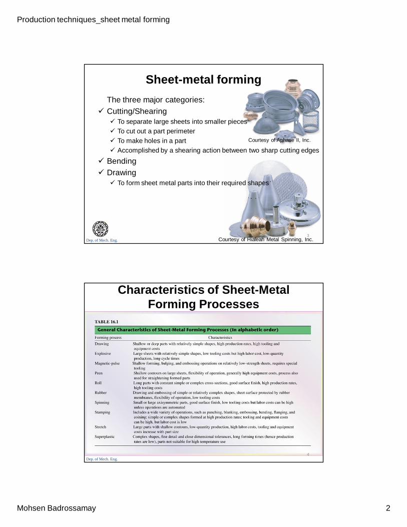
Sheet-metal formingThe three major categories:
Cutting/Shearing To separate large sheets into smaller pieces To cut out a part perimeter To make holes in a part Accomplished by a shearing action between two sharp cutting edges
Bending Drawing
To form sheet metal parts into their required shapes
3
Courtesy of Aphase II, Inc.
Courtesy of Hialeah Metal Spinning, Inc.
Dep. of Mech. Eng.
Characteristics of Sheet-Metal Forming Processes
4
Production techniques_sheet metal forming
Mohsen Badrossamay 3
Dep. of Mech. Eng.
Shearing with a Punch and Die
Major Processing parameters in shearing:
The shape of the punch and die
The speed of punching
Lubrication
The clearance between the punch and the die
5
(a) Schematic illustration of shearing with a punch and die, indicating some of the process variables. Characteristic features of (b) a punched hole and (c) the slug.
Dep. of Mech. Eng.
Shearing
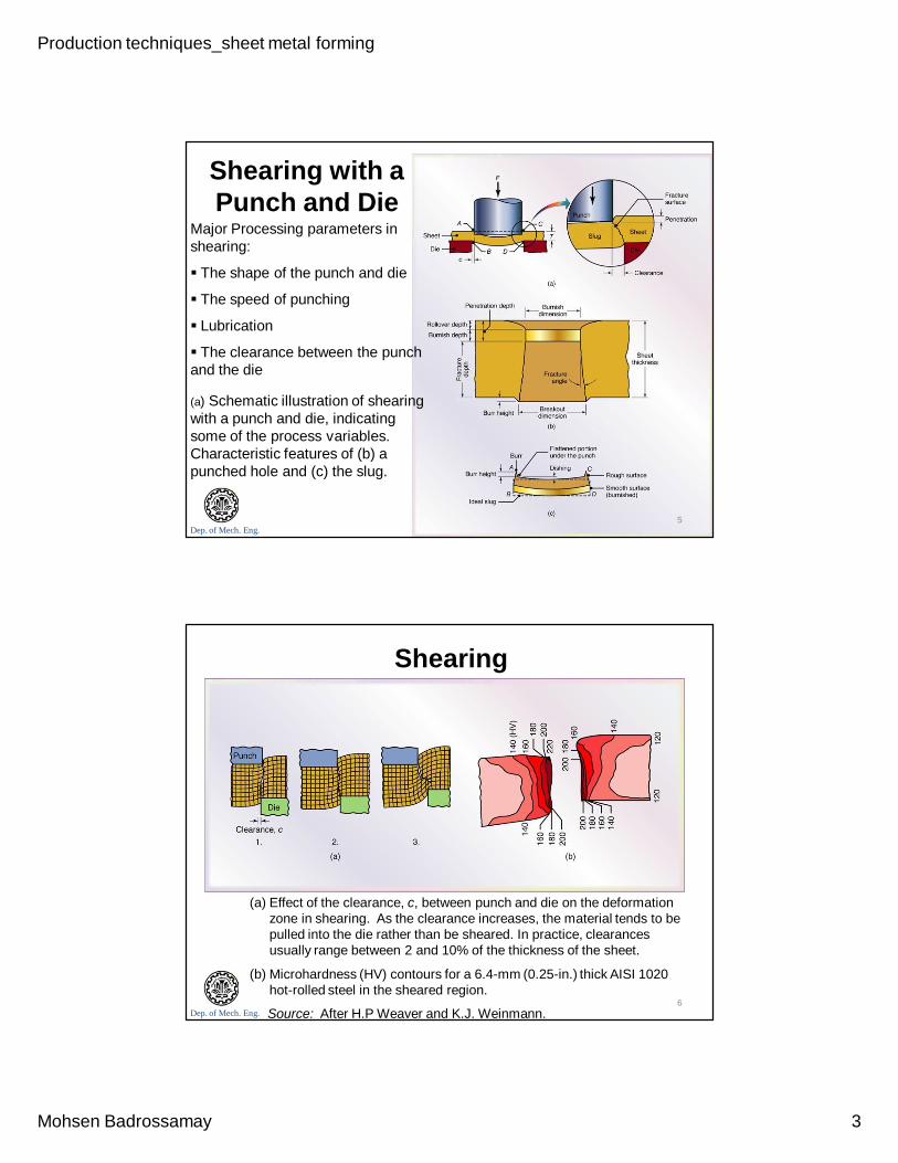
(a) Effect of the clearance, c, between punch and die on the deformation zone in shearing. As the clearance increases, the material tends to be pulled into the die rather than be sheared. In practice, clearances usually range between 2 and 10% of the thickness of the sheet.
(b) Microhardness (HV) contours for a 6.4-mm (0.25-in.) thick AISI 1020 hot-rolled steel in the sheared region.
Source: After H.P Weaver and K.J. Weinmann.6
Production techniques_sheet metal forming
Mohsen Badrossamay 4
Dep. of Mech. Eng.
Clearance Clearance depends on:
The type of material and its temper
The thickness and size of the blank
Its proximity to the edges of other sheared edges or the edges of the original blank
7
Clearances generally range between 2 and 8% of the sheet thickness, but they may be as small as 1% (as fine blanking) or as large as 30%.
As a general guideline:a. Clearances for soft materials are less than those for harder
grades
b. The thicker the sheet, the larger the clearance must be
c. As the ratio of hole diameter to sheet thickness decreases, clearances should be larger
Dep. of Mech. Eng.
Die-Cutting Operations
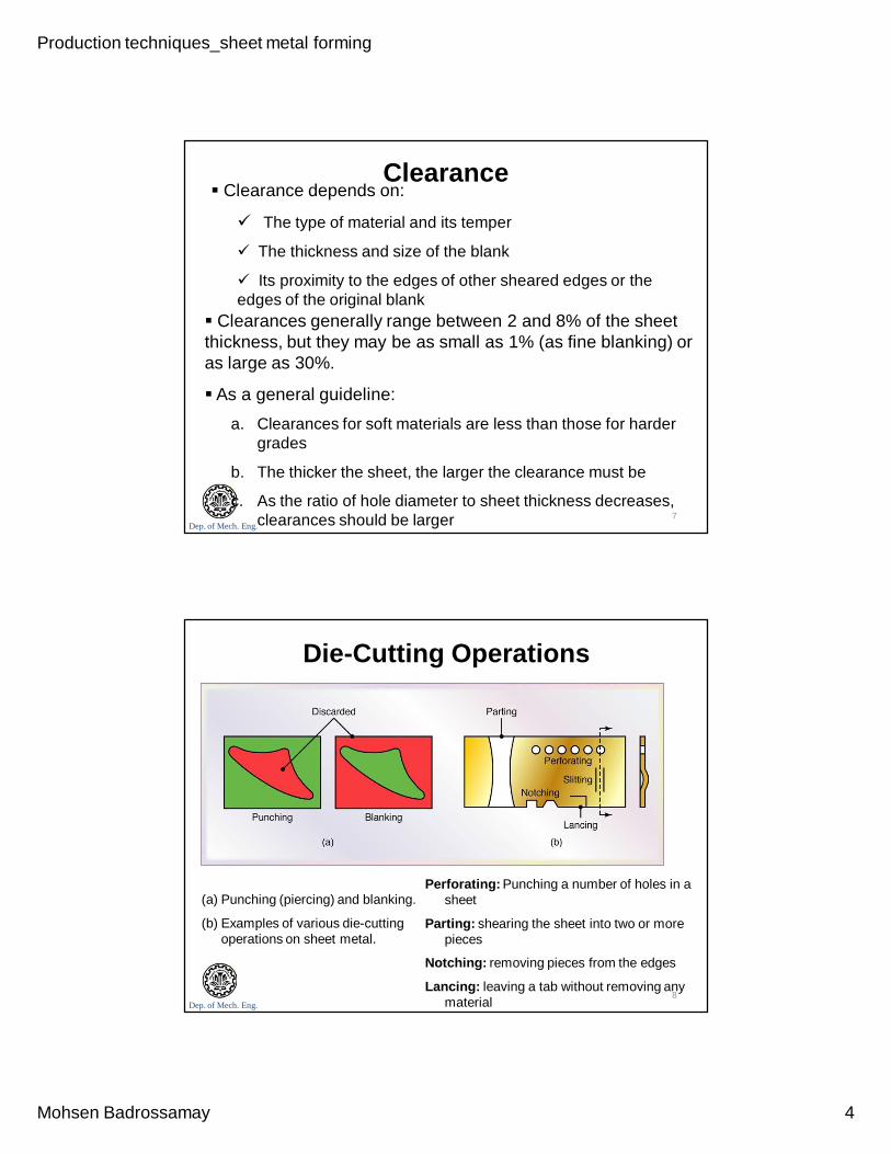
(a) Punching (piercing) and blanking.
(b) Examples of various die-cutting operations on sheet metal.
8
Perforating: Punching a number of holes in a sheet
Parting: shearing the sheet into two or more pieces
Notching: removing pieces from the edges
Lancing: leaving a tab without removing any material
Production techniques_sheet metal forming
Mohsen Badrossamay 5
Dep. of Mech. Eng.
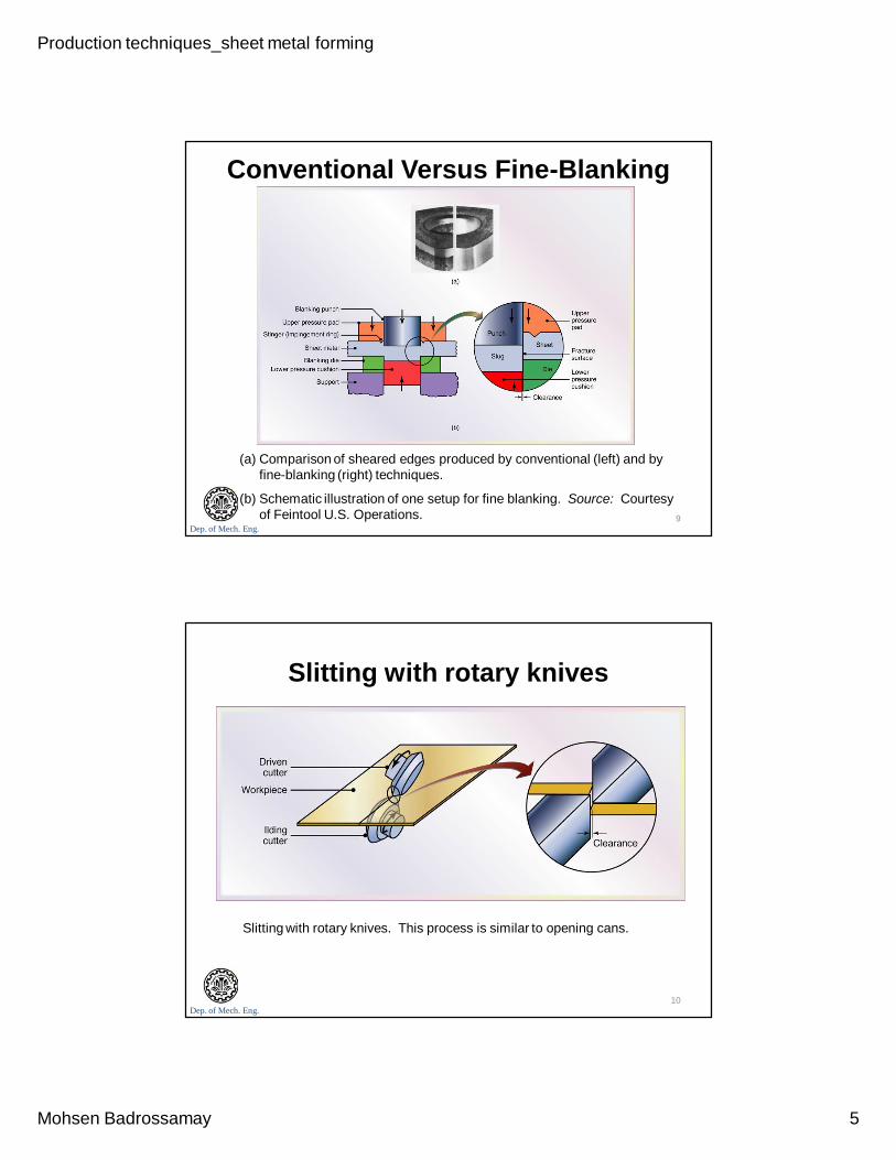
Conventional Versus Fine-Blanking
(a) Comparison of sheared edges produced by conventional (left) and by fine-blanking (right) techniques.
(b) Schematic illustration of one setup for fine blanking. Source: Courtesy of Feintool U.S. Operations. 9
Dep. of Mech. Eng.
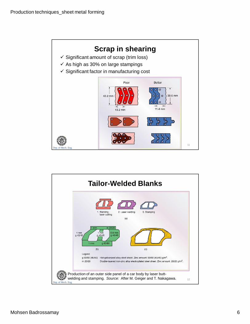
Slitting with rotary knives
Slitting with rotary knives. This process is similar to opening cans.
10
Production techniques_sheet metal forming
Mohsen Badrossamay 6
Dep. of Mech. Eng.
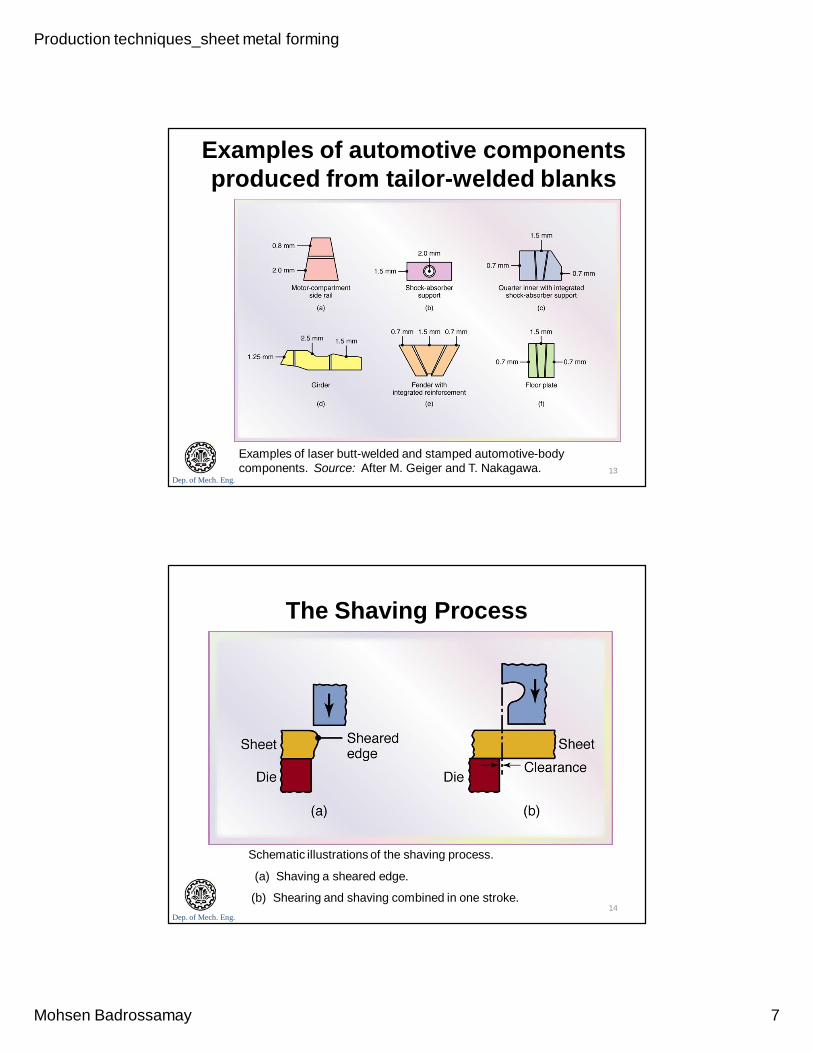
Scrap in shearing Significant amount of scrap (trim loss) As high as 30% on large stampings Significant factor in manufacturing cost
11
Dep. of Mech. Eng.
Tailor-Welded Blanks
Production of an outer side panel of a car body by laser butt-welding and stamping. Source: After M. Geiger and T. Nakagawa. 12
Production techniques_sheet metal forming
Mohsen Badrossamay 7
Dep. of Mech. Eng.
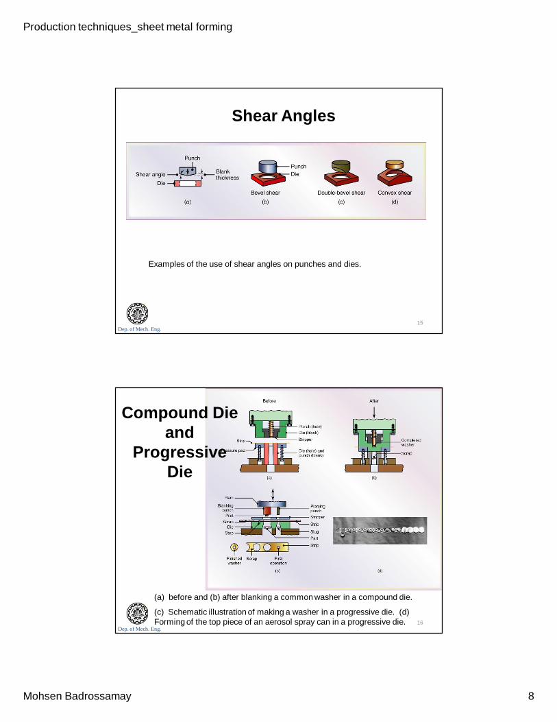
Examples of automotive componentsproduced from tailor-welded blanks
Examples of laser butt-welded and stamped automotive-body components. Source: After M. Geiger and T. Nakagawa. 13
Dep. of Mech. Eng.
The Shaving Process
Schematic illustrations of the shaving process.
(a) Shaving a sheared edge.
(b) Shearing and shaving combined in one stroke.14
Production techniques_sheet metal forming
Mohsen Badrossamay 8
Dep. of Mech. Eng.
Shear Angles
Examples of the use of shear angles on punches and dies.
15
Dep. of Mech. Eng.
Compound Die and
Progressive Die
(a) before and (b) after blanking a common washer in a compound die.
(c) Schematic illustration of making a washer in a progressive die. (d) Forming of the top piece of an aerosol spray can in a progressive die. 16
Production techniques_sheet metal forming
Mohsen Badrossamay 9
Dep. of Mech. Eng.
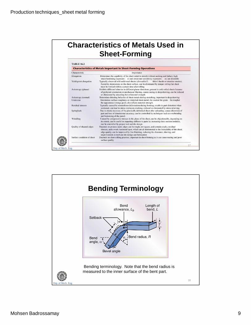
Characteristics of Metals Used in Sheet-Forming
17
Dep. of Mech. Eng.
Bending Terminology
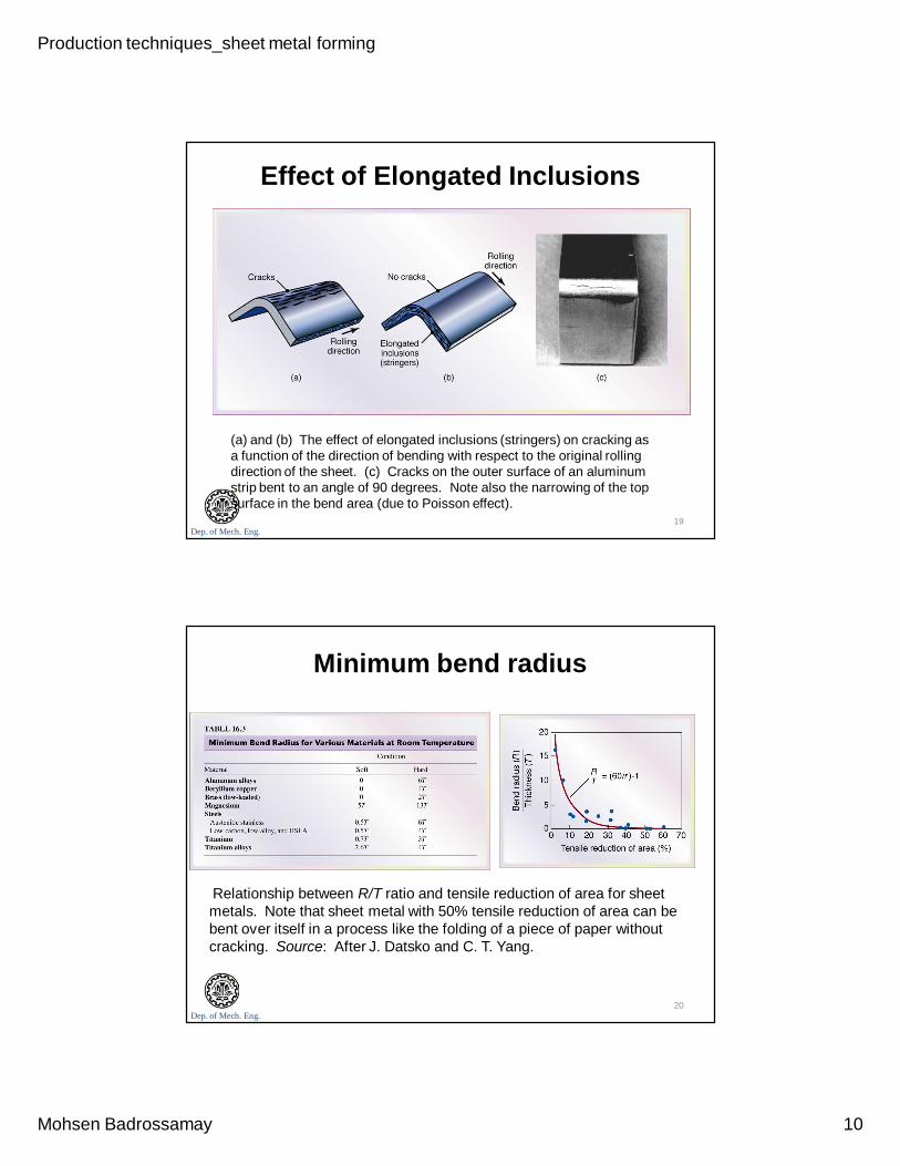
Bending terminology. Note that the bend radius is measured to the inner surface of the bent part.
18
Production techniques_sheet metal forming
Mohsen Badrossamay 10
Dep. of Mech. Eng.
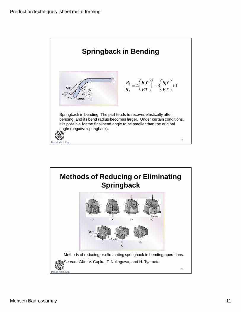
Effect of Elongated Inclusions
(a) and (b) The effect of elongated inclusions (stringers) on cracking as a function of the direction of bending with respect to the original rolling direction of the sheet. (c) Cracks on the outer surface of an aluminum strip bent to an angle of 90 degrees. Note also the narrowing of the top surface in the bend area (due to Poisson effect).
19
Dep. of Mech. Eng.
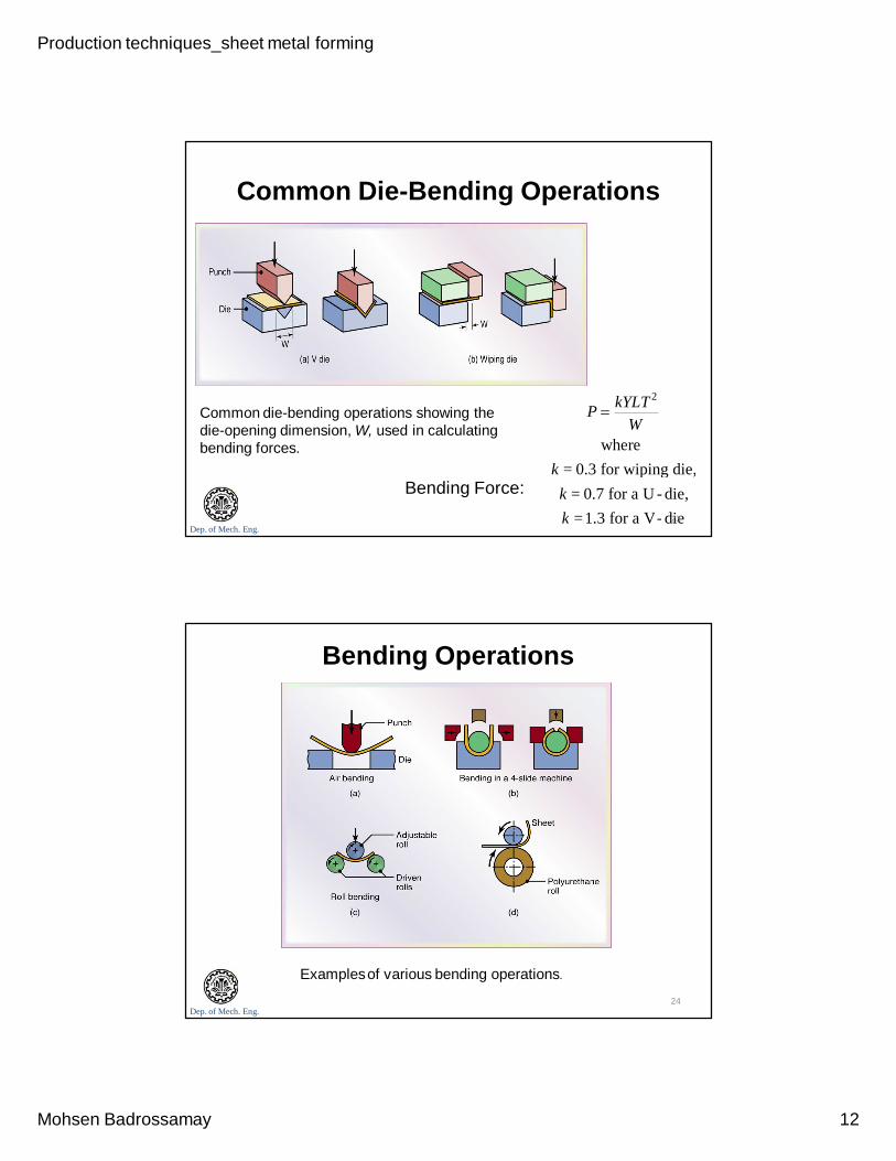
Minimum bend radius
Relationship between R/T ratio and tensile reduction of area for sheet metals. Note that sheet metal with 50% tensile reduction of area can be bent over itself in a process like the folding of a piece of paper without cracking. Source: After J. Datsko and C. T. Yang.
20
Production techniques_sheet metal forming
Mohsen Badrossamay 11
Dep. of Mech. Eng.
Springback in Bending
Springback in bending. The part tends to recover elastically after bending, and its bend radius becomes larger. Under certain conditions, it is possible for the final bend angle to be smaller than the original angle (negative springback).
Ri
R f
4RiYET
3
3RiYET
1
21
Dep. of Mech. Eng.
Methods of Reducing or Eliminating Springback
Methods of reducing or eliminating springback in bending operations.
Source: After V. Cupka, T. Nakagawa, and H. Tyamoto.
22
Production techniques_sheet metal forming
Mohsen Badrossamay 12
Dep. of Mech. Eng.
Common Die-Bending Operations
Common die-bending operations showing the die-opening dimension, W, used in calculating bending forces.
Bending Force:
P kYLT 2
Wwhere
k = 0.3 for wiping die,
k = 0.7 for a U - die,
k =1.3 for a V- die23
Dep. of Mech. Eng.
Bending Operations
Examplesof various bending operations.
24
Production techniques_sheet metal forming
Mohsen Badrossamay 13
Dep. of Mech. Eng.
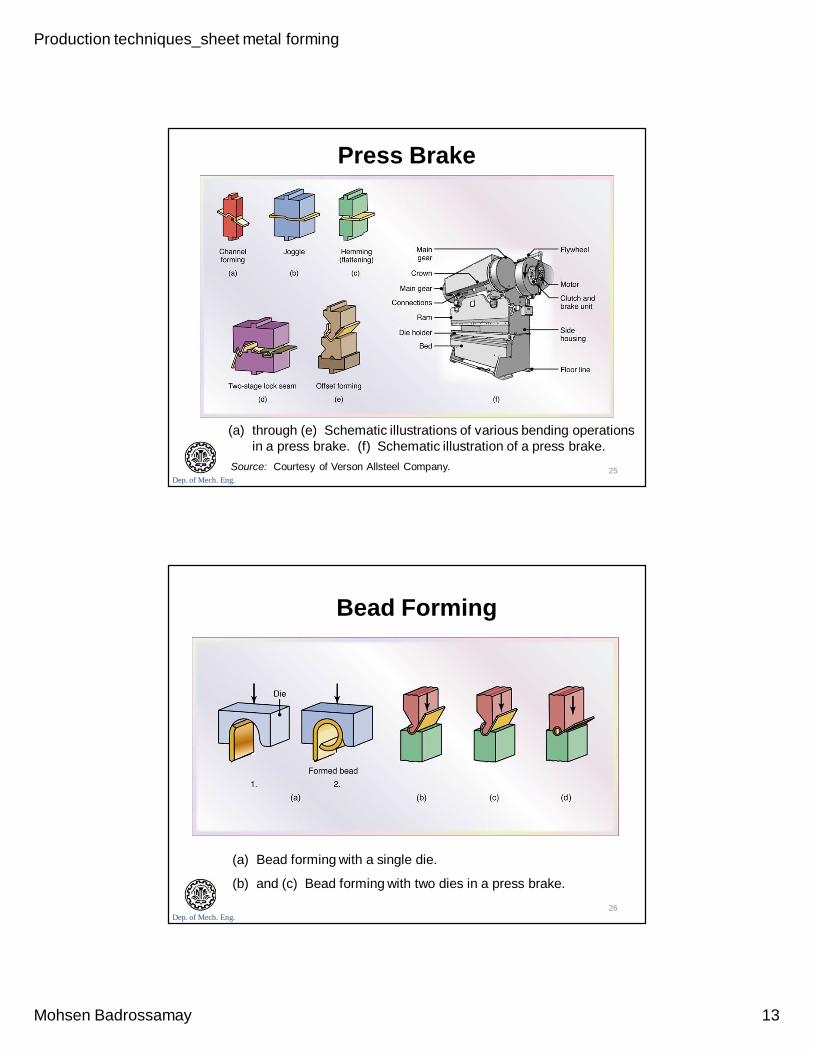
Press Brake
(a) through (e) Schematic illustrations of various bending operations in a press brake. (f) Schematic illustration of a press brake.
Source: Courtesy of Verson Allsteel Company. 25
Dep. of Mech. Eng.
Bead Forming
(a) Bead forming with a single die.
(b) and (c) Bead forming with two dies in a press brake.
26
Production techniques_sheet metal forming
Mohsen Badrossamay 14
Dep. of Mech. Eng.
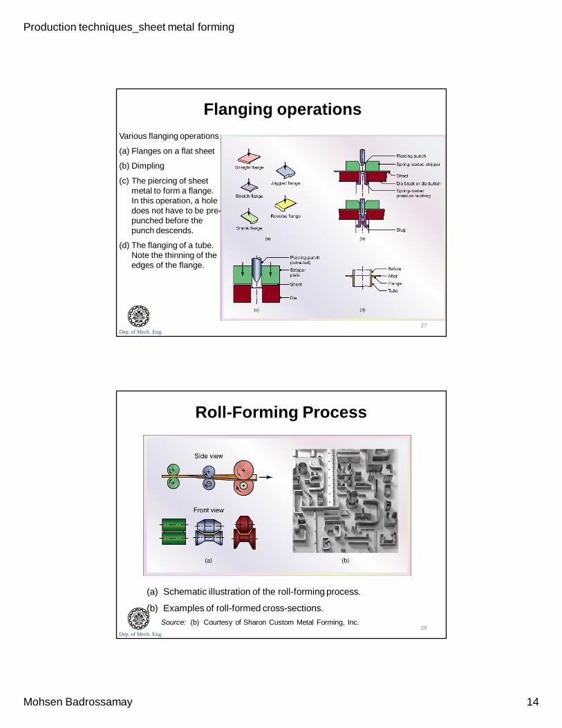
Flanging operationsVarious flanging operations
(a) Flanges on a flat sheet
(b) Dimpling
(c) The piercing of sheet metal to form a flange. In this operation, a hole does not have to be pre-punched before the punch descends.
(d) The flanging of a tube. Note the thinning of the edges of the flange.
27
Dep. of Mech. Eng.
Roll-Forming Process
(a) Schematic illustration of the roll-forming process.
(b) Examples of roll-formed cross-sections.Source: (b) Courtesy of Sharon Custom Metal Forming, Inc.
28
Production techniques_sheet metal forming
Mohsen Badrossamay 15
Dep. of Mech. Eng.
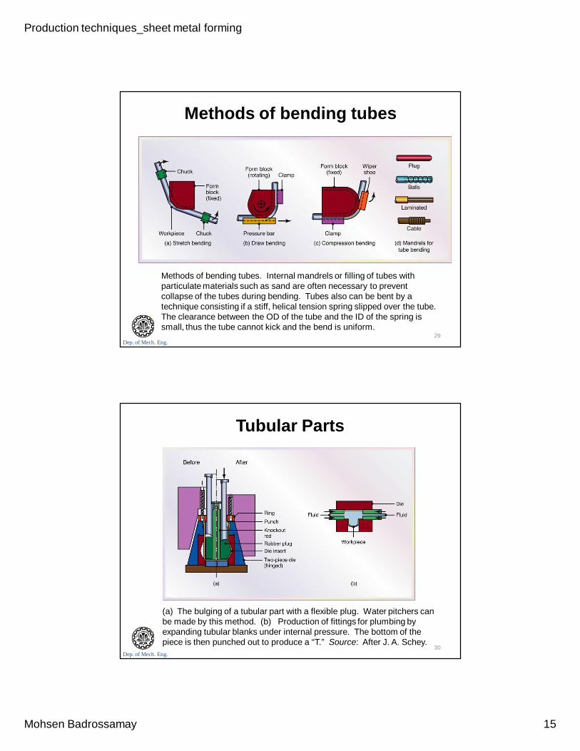
Methods of bending tubes
Methods of bending tubes. Internal mandrels or filling of tubes with particulate materials such as sand are often necessary to prevent collapse of the tubes during bending. Tubes also can be bent by a technique consisting if a stiff, helical tension spring slipped over the tube. The clearance between the OD of the tube and the ID of the spring is small, thus the tube cannot kick and the bend is uniform.
29
Dep. of Mech. Eng.
Tubular Parts
(a) The bulging of a tubular part with a flexible plug. Water pitchers can be made by this method. (b) Production of fittings for plumbing by expanding tubular blanks under internal pressure. The bottom of the piece is then punched out to produce a “T.” Source: After J. A. Schey.
30
Production techniques_sheet metal forming
Mohsen Badrossamay 16
Dep. of Mech. Eng.
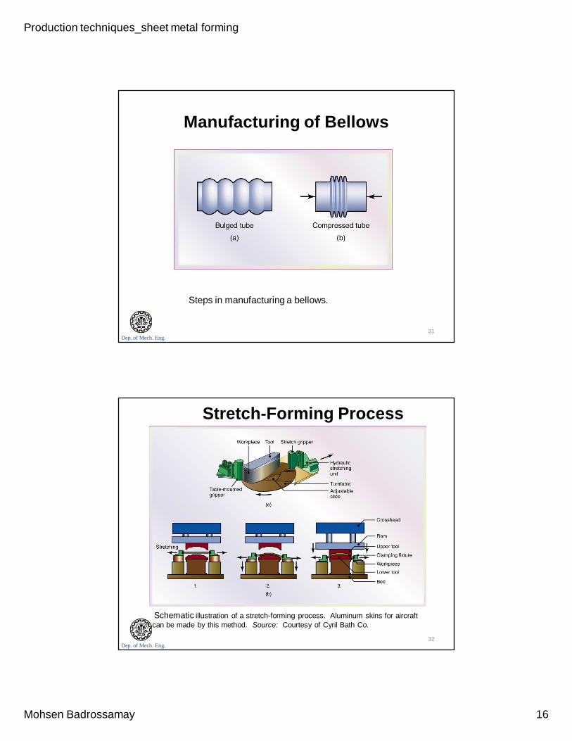
Manufacturing of Bellows
Steps in manufacturing a bellows.
31
Dep. of Mech. Eng.
Stretch-Forming Process
Schematic illustration of a stretch-forming process. Aluminum skins for aircraft can be made by this method. Source: Courtesy of Cyril Bath Co.
32
Production techniques_sheet metal forming
Mohsen Badrossamay 17
Dep. of Mech. Eng.
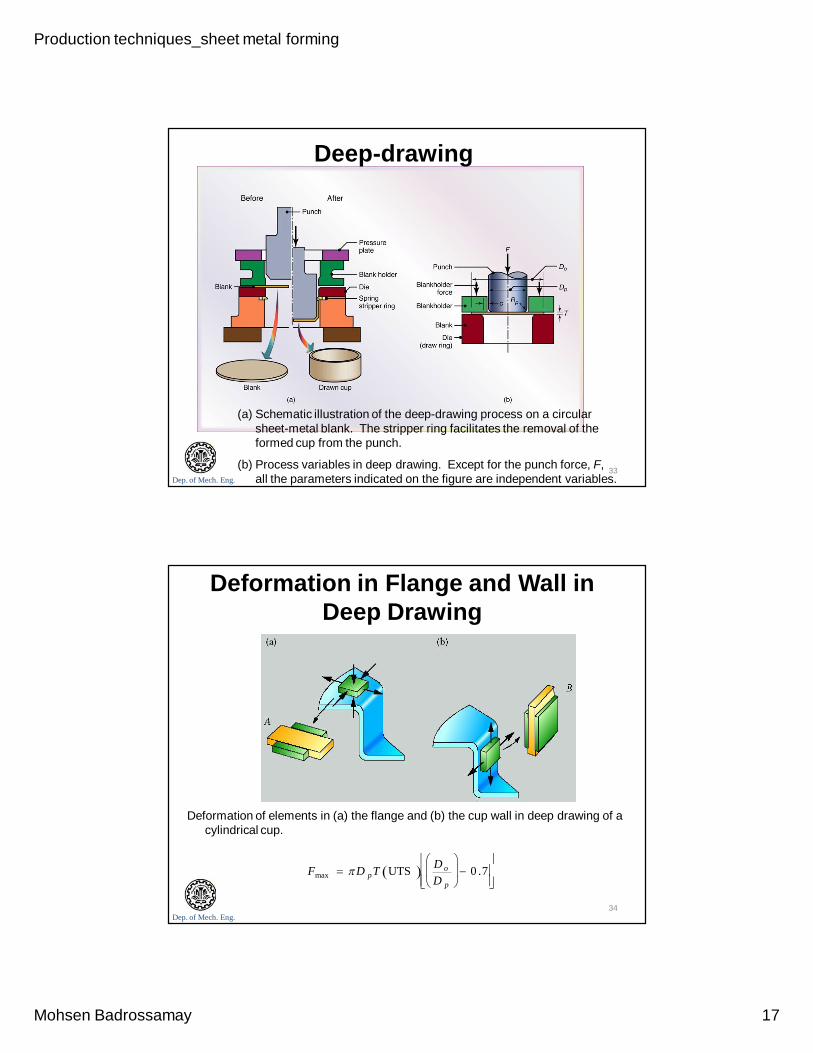
Deep-drawing
(a) Schematic illustration of the deep-drawing process on a circular sheet-metal blank. The stripper ring facilitates the removal of the formed cup from the punch.
(b) Process variables in deep drawing. Except for the punch force, F, all the parameters indicated on the figure are independent variables.
33
Dep. of Mech. Eng.
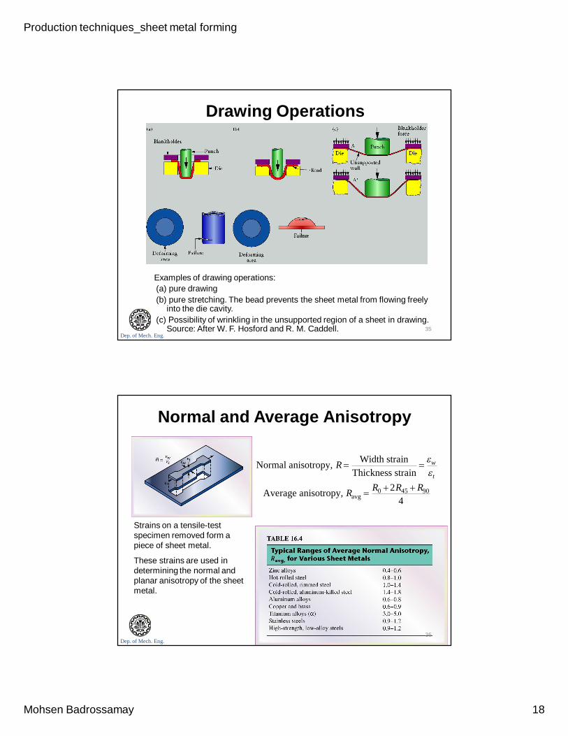
Deformation in Flange and Wall in Deep Drawing
Deformation of elements in (a) the flange and (b) the cup wall in deep drawing of a cylindrical cup.
Fmax D pT UTS D o
D p
0 .7
34
Production techniques_sheet metal forming
Mohsen Badrossamay 18
Dep. of Mech. Eng.
Drawing Operations
Examples of drawing operations:(a) pure drawing(b) pure stretching. The bead prevents the sheet metal from flowing freely
into the die cavity.(c) Possibility of wrinkling in the unsupported region of a sheet in drawing.
Source: After W. F. Hosford and R. M. Caddell. 35
Dep. of Mech. Eng.
Normal and Average Anisotropy
Strains on a tensile-test specimen removed form a piece of sheet metal.
These strains are used in determining the normal and planar anisotropy of the sheet metal.
Normal anisotropy, R Width strainThickness strain
w
t
Average anisotropy, Ravg R0 2R45 R90
4
36
Production techniques_sheet metal forming
Mohsen Badrossamay 19
Dep. of Mech. Eng.
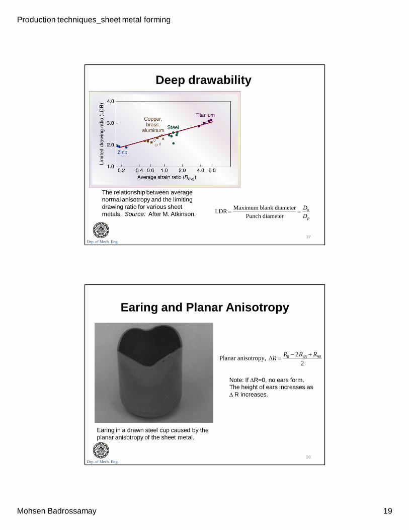
Deep drawability
The relationship between average normal anisotropy and the limiting drawing ratio for various sheet metals. Source: After M. Atkinson. LDR Maximum blank diameter
Punch diameter Do
Dp
37
Dep. of Mech. Eng.
Earing and Planar Anisotropy
Earing in a drawn steel cup caused by the planar anisotropy of the sheet metal.
Planar anisotropy, R R0 2R45 R90
2
Note: If R=0, no ears form. The height of ears increases as R increases.
38
Production techniques_sheet metal forming
Mohsen Badrossamay 20
Dep. of Mech. Eng.
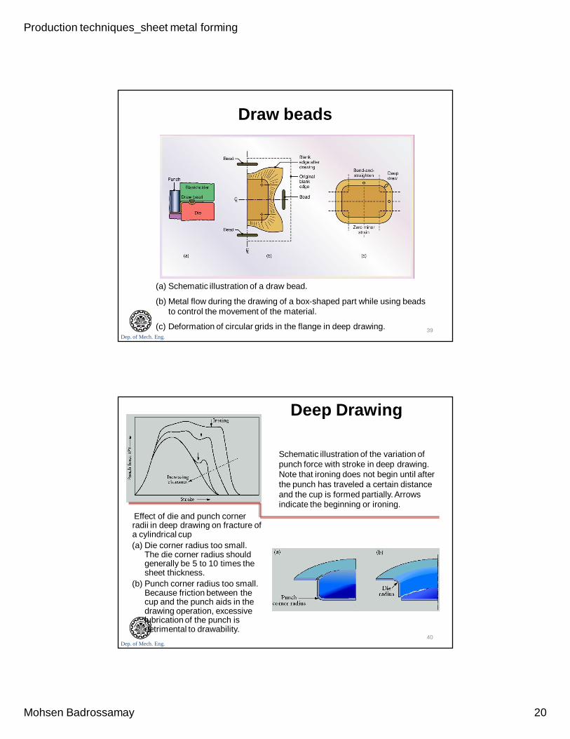
Draw beads
(a) Schematic illustration of a draw bead.
(b) Metal flow during the drawing of a box-shaped part while using beads to control the movement of the material.
(c) Deformation of circular grids in the flange in deep drawing. 39
Dep. of Mech. Eng.
Deep Drawing
Schematic illustration of the variation of punch force with stroke in deep drawing. Note that ironing does not begin until after the punch has traveled a certain distance and the cup is formed partially. Arrows indicate the beginning or ironing.
Effect of die and punch corner radii in deep drawing on fracture of a cylindrical cup(a) Die corner radius too small.
The die corner radius should generally be 5 to 10 times the sheet thickness.
(b) Punch corner radius too small. Because friction between the cup and the punch aids in the drawing operation, excessive lubrication of the punch is detrimental to drawability.
40
Production techniques_sheet metal forming
Mohsen Badrossamay 21
Dep. of Mech. Eng.
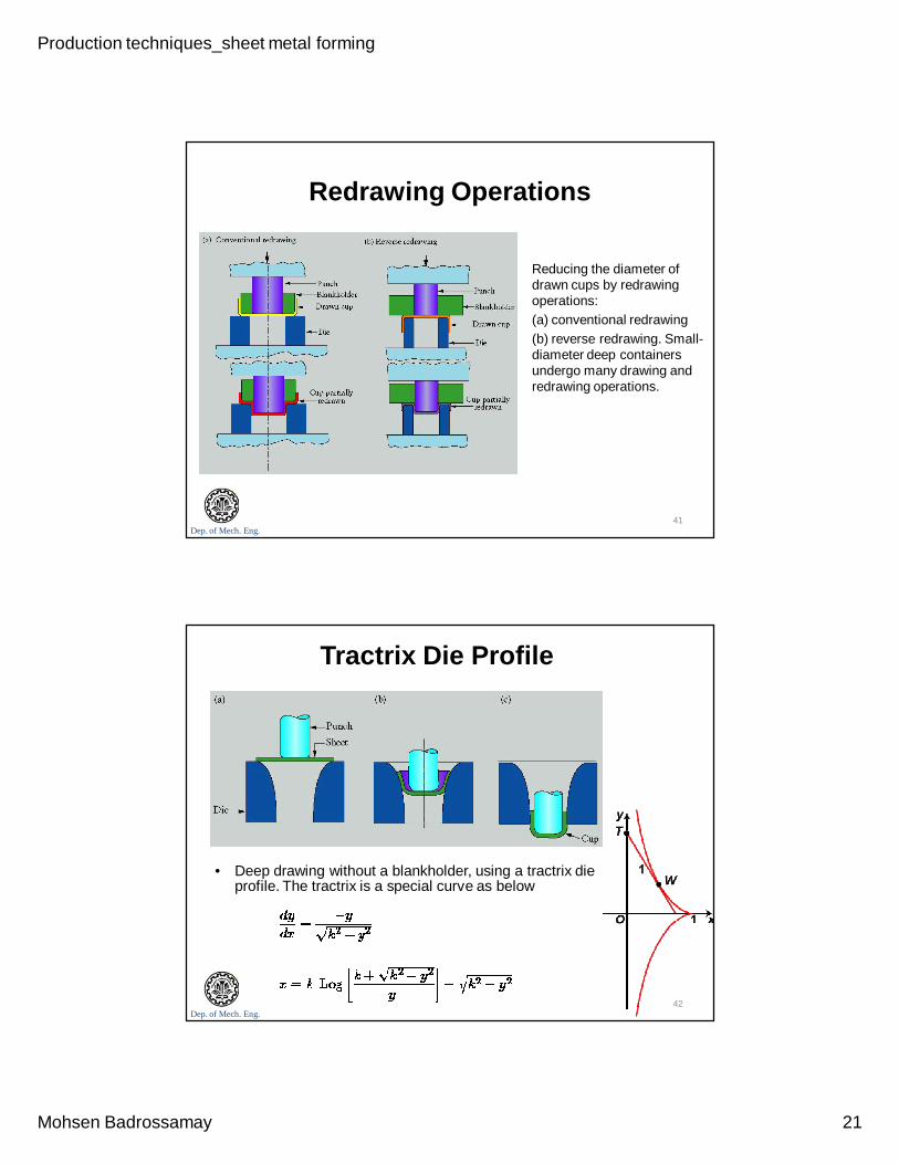
Redrawing Operations
• Reducing the diameter of drawn cups by redrawing operations:
• (a) conventional redrawing • (b) reverse redrawing. Small-
diameter deep containers undergo many drawing and redrawing operations.
41
Dep. of Mech. Eng.
Tractrix Die Profile
• Deep drawing without a blankholder, using a tractrix die profile. The tractrix is a special curve as below
42
Production techniques_sheet metal forming
Mohsen Badrossamay 22
Dep. of Mech. Eng.
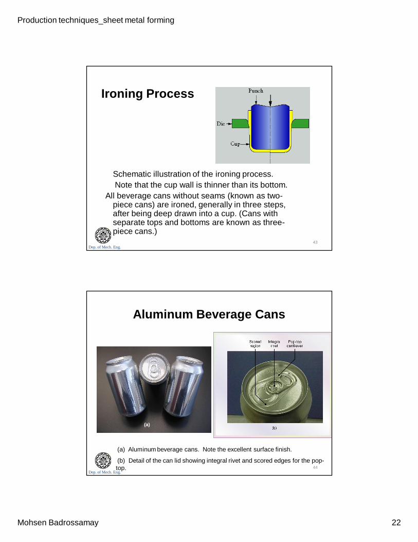
Ironing Process
Schematic illustration of the ironing process. Note that the cup wall is thinner than its bottom.
All beverage cans without seams (known as two-piece cans) are ironed, generally in three steps, after being deep drawn into a cup. (Cans with separate tops and bottoms are known as three-piece cans.)
43
Dep. of Mech. Eng.
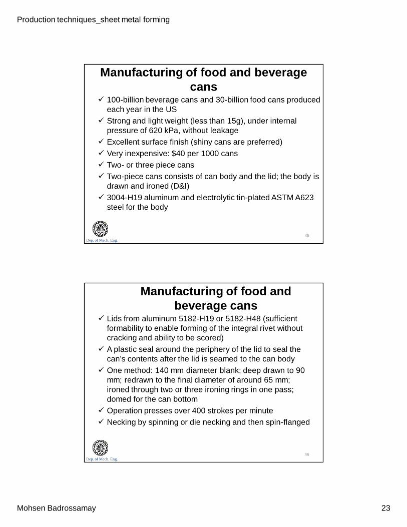
Aluminum Beverage Cans
(a) Aluminum beverage cans. Note the excellent surface finish.
(b) Detail of the can lid showing integral rivet and scored edges for the pop-top.
(a)
44
Production techniques_sheet metal forming
Mohsen Badrossamay 23
Dep. of Mech. Eng.
Manufacturing of food and beverage cans
100-billion beverage cans and 30-billion food cans produced each year in the US
Strong and light weight (less than 15g), under internal pressure of 620 kPa, without leakage
Excellent surface finish (shiny cans are preferred) Very inexpensive: $40 per 1000 cans Two- or three piece cans Two-piece cans consists of can body and the lid; the body is
drawn and ironed (D&I) 3004-H19 aluminum and electrolytic tin-plated ASTM A623
steel for the body
45
Dep. of Mech. Eng.
Manufacturing of food and beverage cans
Lids from aluminum 5182-H19 or 5182-H48 (sufficient formability to enable forming of the integral rivet without cracking and ability to be scored)
A plastic seal around the periphery of the lid to seal the can’s contents after the lid is seamed to the can body
One method: 140 mm diameter blank; deep drawn to 90 mm; redrawn to the final diameter of around 65 mm; ironed through two or three ironing rings in one pass; domed for the can bottom
Operation presses over 400 strokes per minute Necking by spinning or die necking and then spin-flanged
46
Production techniques_sheet metal forming
Mohsen Badrossamay 24
Dep. of Mech. Eng.
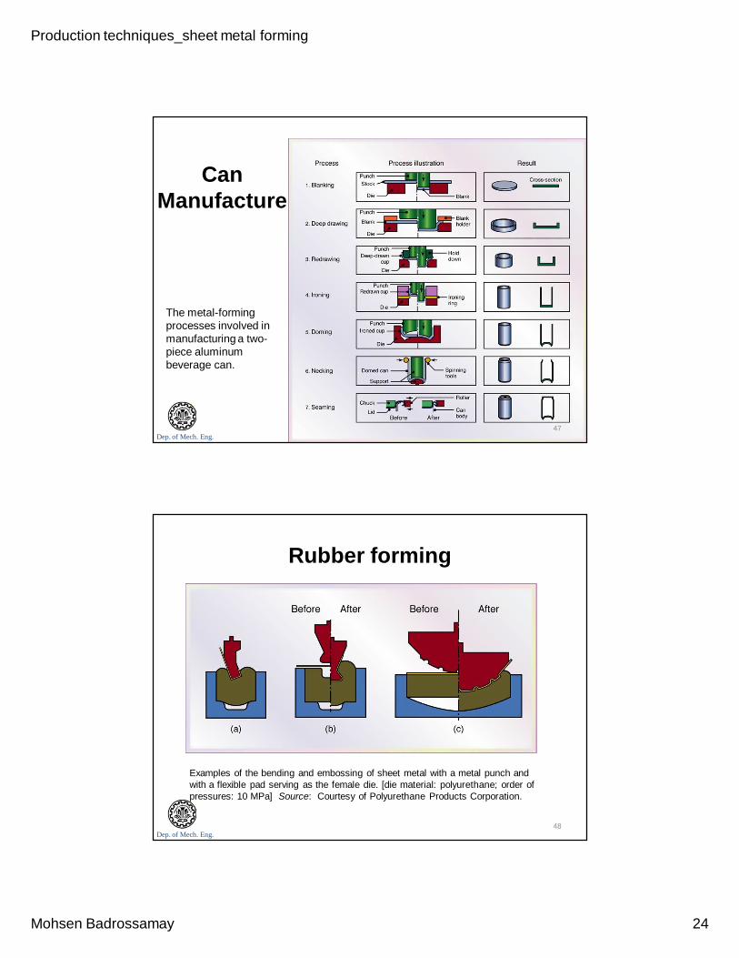
Can Manufacture
The metal-forming processes involved in manufacturing a two-piece aluminum beverage can.
47
Dep. of Mech. Eng.
Rubber forming
Examples of the bending and embossing of sheet metal with a metal punch and with a flexible pad serving as the female die. [die material: polyurethane; order of pressures: 10 MPa] Source: Courtesy of Polyurethane Products Corporation.
48
Production techniques_sheet metal forming
Mohsen Badrossamay 25
Dep. of Mech. Eng.
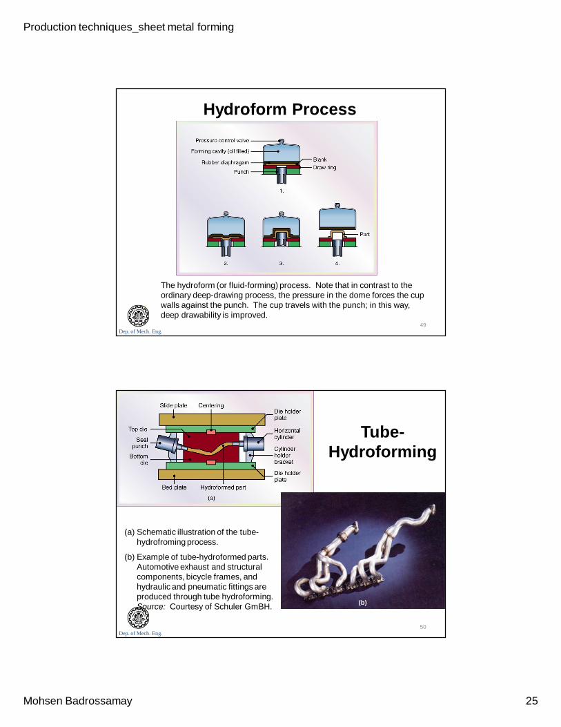
Hydroform Process
The hydroform (or fluid-forming) process. Note that in contrast to the ordinary deep-drawing process, the pressure in the dome forces the cup walls against the punch. The cup travels with the punch; in this way, deep drawability is improved.
49
Dep. of Mech. Eng.
Tube-Hydroforming
(a) Schematic illustration of the tube-hydrofroming process.
(b) Example of tube-hydroformed parts. Automotive exhaust and structural components, bicycle frames, and hydraulic and pneumatic fittings are produced through tube hydroforming. Source: Courtesy of Schuler GmBH. (b)
50
Production techniques_sheet metal forming
Mohsen Badrossamay 26
Dep. of Mech. Eng.
Spinning Spinning is a process which involves the forming of
axisymmetric parts over a mandrel by the use of various tools and rollers
Conventional spinning, a circular blank of flat or preformed sheet metal is placed and held against a mandrel and rotated while a rigid toll deforms and shapes the material over the mandrel
Shear spinning, also known flow turning, hydrospinning, and spin forging. Single or two forming roller(s) is/are used to reduce sheet’s thickness while maintaining its maximum blank diameter
Tube spinning, reducing or shaping the thickness of hollow cylindrical blanks by spinning them on a solid and round mandrel using rollers
51
Dep. of Mech. Eng.
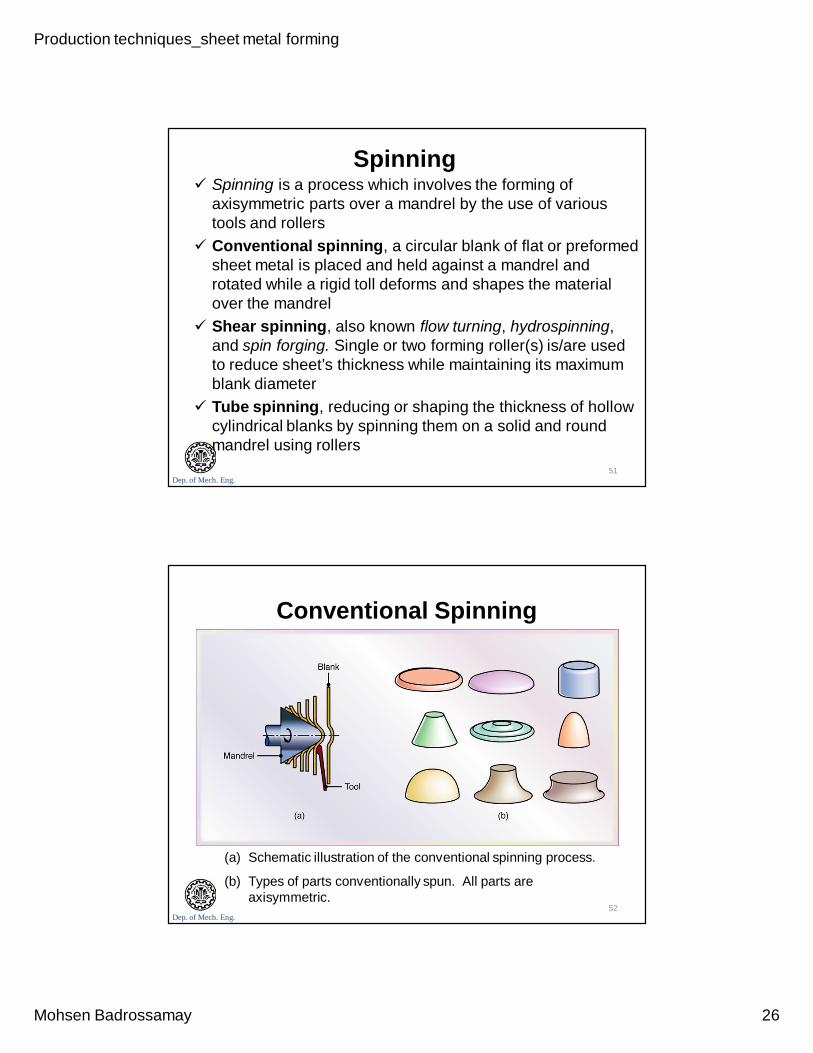
Conventional Spinning
(a) Schematic illustration of the conventional spinning process.
(b) Types of parts conventionally spun. All parts are axisymmetric.
52
Production techniques_sheet metal forming
Mohsen Badrossamay 27
Dep. of Mech. Eng.
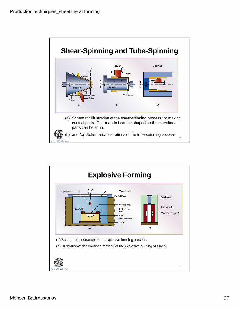
Shear-Spinning and Tube-Spinning
(a) Schematic illustration of the shear-spinning process for making conical parts. The mandrel can be shaped so that curvilinear parts can be spun.
(b) and (c) Schematic illustrations of the tube-spinning process53
Dep. of Mech. Eng.
Explosive Forming
(a) Schematic illustration of the explosive forming process.
(b) Illustration of the confined method of the explosive bulging of tubes.
54
Production techniques_sheet metal forming
Mohsen Badrossamay 28
Dep. of Mech. Eng.
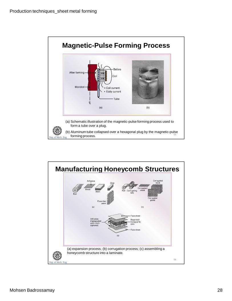
Magnetic-Pulse Forming Process
(a) Schematic illustration of the magnetic-pulse forming process used to form a tube over a plug.
(b) Aluminum tube collapsed over a hexagonal plug by the magnetic-pulse forming process. 55
Dep. of Mech. Eng.
Manufacturing Honeycomb Structures
(a) expansion process; (b) corrugation process; (c) assembling a honeycomb structure into a laminate.
56

Production techniques_sheet metal forming
Mohsen Badrossamay 29
Dep. of Mech. Eng.
Design considerations in sheet-metal forming
Blank design, material scrap is the primary concern in blanking operations
Bending, the main concerns are material fracture, wrinkling, and the inability to form the bend Relief notch cut to limit the stresses and to avoid tearing Design modification to remove stress concentrations
Stamping and progressive-die, cost of the tooling and the number of stations are determined by the number of features and spacing of the features on the part
57
Dep. of Mech. Eng.
Blank design
Efficient nesting of parts for optimum material utilization in blanking. Source: Courtesy of Society of Manufacturing Engineers.
58
Production techniques_sheet metal forming
Mohsen Badrossamay 30
Dep. of Mech. Eng.
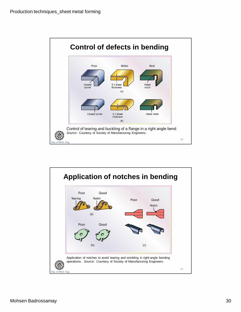
Control of defects in bending
Control of tearing and buckling of a flange in a right angle bend. Source: Courtesy of Society of Manufacturing Engineers.
59
Dep. of Mech. Eng.
Application of notches in bending
Application of notches to avoid tearing and wrinkling in right-angle bending operations. Source: Courtesy of Society of Manufacturing Engineers.
60
Production techniques_sheet metal forming
Mohsen Badrossamay 31
Dep. of Mech. Eng.
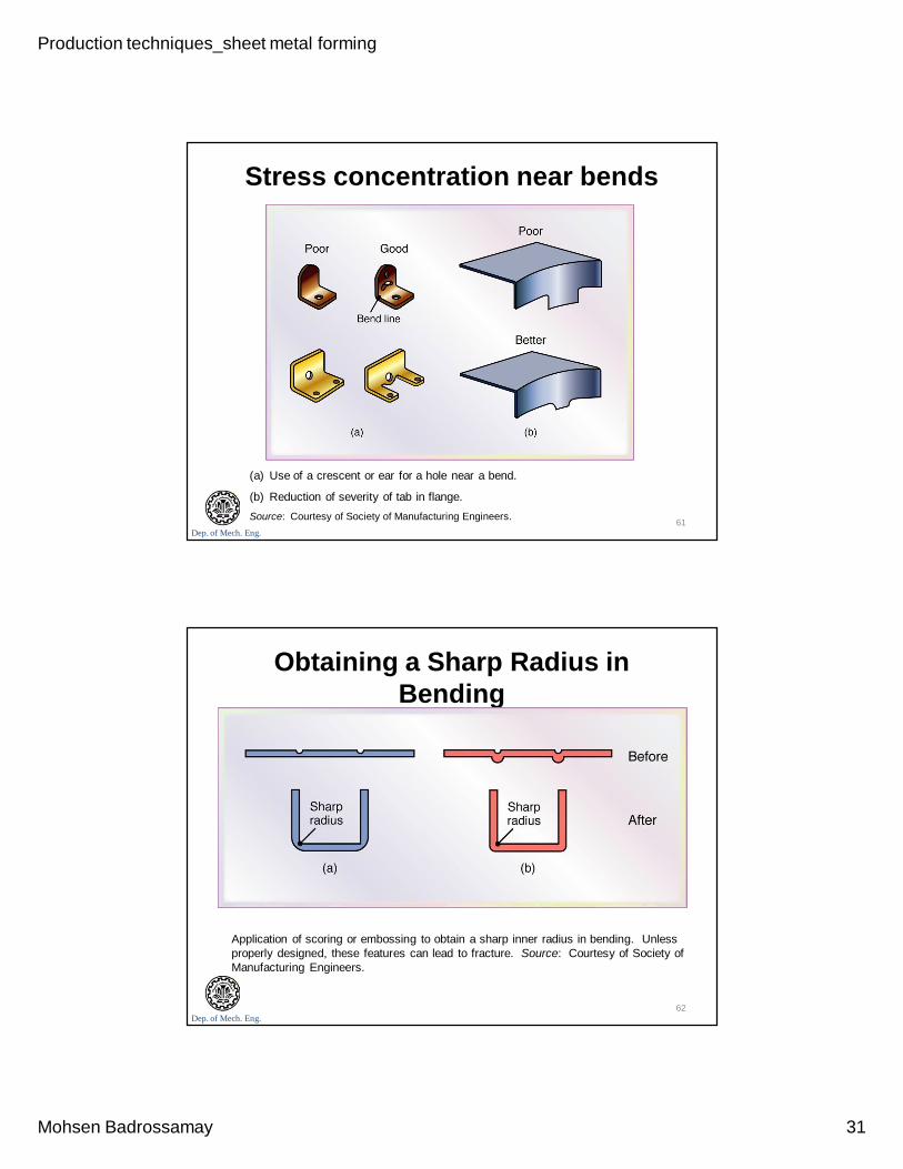
Stress concentration near bends
(a) Use of a crescent or ear for a hole near a bend.
(b) Reduction of severity of tab in flange. Source: Courtesy of Society of Manufacturing Engineers. 61
Dep. of Mech. Eng.
Obtaining a Sharp Radius in Bending
Application of scoring or embossing to obtain a sharp inner radius in bending. Unless properly designed, these features can lead to fracture. Source: Courtesy of Society of Manufacturing Engineers.
62
Production techniques_sheet metal forming
Mohsen Badrossamay 32
Dep. of Mech. Eng.
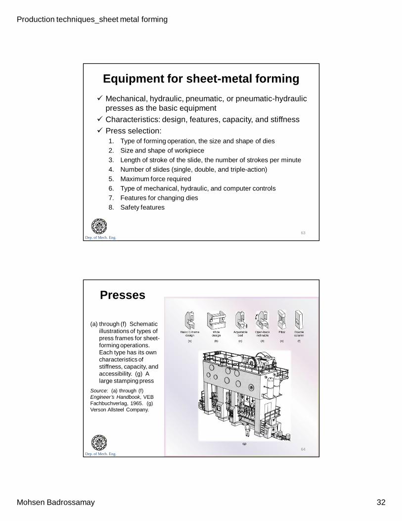
Equipment for sheet-metal forming Mechanical, hydraulic, pneumatic, or pneumatic-hydraulic
presses as the basic equipment Characteristics: design, features, capacity, and stiffness Press selection:
1. Type of forming operation, the size and shape of dies2. Size and shape of workpiece3. Length of stroke of the slide, the number of strokes per minute4. Number of slides (single, double, and triple-action)5. Maximum force required6. Type of mechanical, hydraulic, and computer controls7. Features for changing dies8. Safety features
63
Dep. of Mech. Eng.
Presses
(a) through (f) Schematic illustrations of types of press frames for sheet-forming operations. Each type has its own characteristics of stiffness, capacity, and accessibility. (g) A large stamping press
Source: (a) through (f) Engineer’s Handbook, VEB Fachbuchverlag, 1965. (g) Verson Allsteel Company.
64
Production techniques_sheet metal forming
Mohsen Badrossamay 33
Dep. of Mech. Eng.
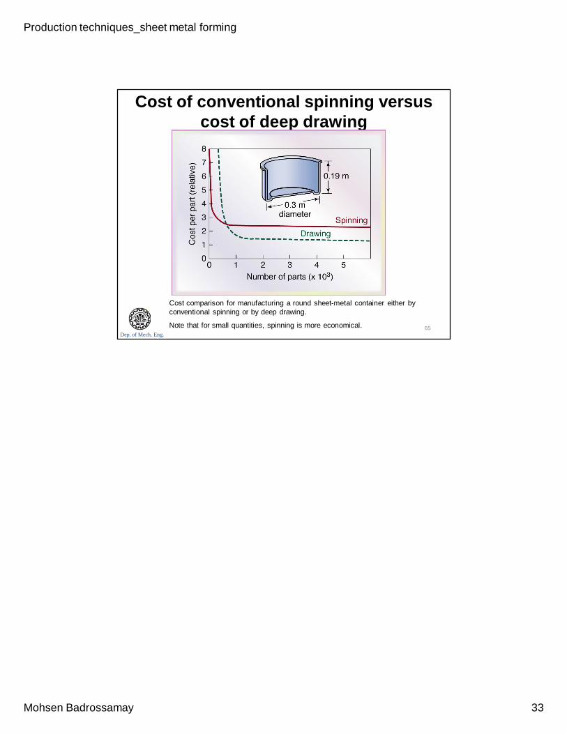
Cost of conventional spinning versus cost of deep drawing
Cost comparison for manufacturing a round sheet-metal container either by conventional spinning or by deep drawing.
Note that for small quantities, spinning is more economical. 65