sheet molded compound (smc) panel bonding
TRANSCRIPT

Document ID# 1655994 2006 Chevrolet Corvette
Sheet Molded Compound (SMC) Panel Bonding This is intended to provide general guidelines for sheet molded compound (SMC) and carbon fiber adhesive bonding of full panel replacement in regards to collision repair procedures.
Sectioning, partial panel of full panels, is not supported by General Motors unless specifically documented in a Service Bulletin or Manual.
Important:
• Prepare the surfaces to be bonded according to adhesive manufacturer's recommendations. Many adhesive manufacturers have different preparation methods. Do not intermix adhesive manufacturers systems. Mixing materials from different manufacturers can produce unsatisfactory results.
• DO NOT top coat any adhesive bonding mating surface. Use primer only on bonding surfaces. Refer to adhesive manufacturer's recommendations for priming applications.
Adhesives currently meeting the performance requirements include General Motors materials and products manufactured by Ashland and Lord Fusor. At this time, ONLY the adhesive products listed below meet this guideline:
GM Goodwrench®
GMSPO of Canada
Ashland Pliogrip® Structural Adhesives Crest Industries, Inc.
1-800-822-4100
Lord Fusor Structural Adhesive Product
Type 89020330 8902332 7770B 127 EZ Medium Set
N/A N/A 7779B N/A Fast Set Canadian applications may use U.S. part numbers. Refer to your GM Dealer Parts Department for the correct part number applications.
Document ID# 1655994 2006 Chevrolet Corvette

Document ID# 1655994 2008 Chevrolet Corvette
Sheet Molded Compound (SMC) Panel Bonding This is intended to provide general guidelines for sheet molded compound (SMC) and carbon fiber adhesive bonding of full panel replacement in regards to collision repair procedures.
Sectioning, partial panel of full panels, is not supported by General Motors unless specifically documented in a Service Bulletin or Manual. Important:
• Prepare the surfaces to be bonded according to adhesive manufacturer's recommendations. Many adhesive manufacturers have different preparation methods. Do not intermix adhesive manufacturers systems. Mixing materials from different manufacturers can produce unsatisfactory results.
• DO NOT top coat any adhesive bonding mating surface. Use primer only on bonding surfaces. Refer to adhesive manufacturer's recommendations for priming applications.
Adhesives currently meeting the performance requirements include General Motors materials and products manufactured by Ashland and Lord Fusor. At this time, ONLY the adhesive products listed below meet this guideline:
GM Goodwrench®
GMSPO of Canada
Ashland Pliogrip Structural Adhesives Crest Industries, Inc
1-800-822-4100
Lord Fusor Structural Adhesive Product
Type
89020330 8902332 7770B 127 EZ Medium Set
N/A N/A 7779B N/A Fast Set Canadian applications may use U.S. part numbers. Refer to your GM Dealer Parts Department for the correct part number applications.
Document ID# 1655994 2008 Chevrolet Corvette


Document ID# 1655994 2008 Cadillac XLR
Sheet Molded Compound (SMC) Panel Bonding This is intended to provide general guidelines for sheet molded compound (SMC) and carbon fiber adhesive bonding of full panel replacement in regards to collision repair procedures.
Sectioning, partial panel of full panels, is not supported by General Motors unless specifically documented in a Service Bulletin or Manual. Important:
• Prepare the surfaces to be bonded according to adhesive manufacturer's recommendations. Many adhesive manufacturers have different preparation methods. Do not intermix adhesive manufacturers systems. Mixing materials from different manufacturers can produce unsatisfactory results.
• DO NOT top coat any adhesive bonding mating surface. Use primer only on bonding surfaces. Refer to adhesive manufacturer's recommendations for priming applications.
Adhesives currently meeting the performance requirements include General Motors materials and products manufactured by Ashland and Lord Fusor. At this time, ONLY the adhesive products listed below meet this guideline:
GM Goodwrench®
GMSPO of Canada
Ashland Pliogrip Structural Adhesives Crest Industries, Inc
1-800-822-4100
Lord Fusor Structural Adhesive Product
Type
89020330 8902332 7770B 127 EZ Medium Set
N/A N/A 7779B N/A Fast Set Canadian applications may use U.S. part numbers. Refer to your GM Dealer Parts Department for the correct part number applications.
Document ID# 1655994 2008 Cadillac XLR


Ashland Specialty Chemical
Specialty Polymers & Adhesives Division of Ashland Inc. P.O. Box 2219, Columbus, OH 43216
5200 Blazer Parkway, Dublin, OH 43017
- 1 -
PLIOGRIP® OEM ADHESIVE APPLICATIONS
Automotive
PLIOGRIP® is the preferred adhesive for the Automotive manufacturers listed below and has been used in applications, including but not limited to…
Fender Hood
Removable Hardtop Deck Lid Spoiler
Window Clip Valve-Cover Assembly
Bumper Lift Gate
Grill Tail Gate
Roof Roof Hatch
Quarter Panels
GENERAL MOTORS COMPANY – US Brands
PROGRAM MODEL YEAR(S) Pontiac Fiero 1984-1987
GM 200 Vans (GM Lumina, Pontiac Transam, Olds Silhouette)
1988-1993
Chevrolet Camaro CFIV 1994-2002 Pontiac Firebird CFIV 1994-2002
Chevrolet Corvette C1 – C4 1984-2004 Military (H1) Hummer (Original: AMGeneral)
1983-2004
H2 Hummer SUV 2002-2004 Pick-Up/Utility Trucks
GMT 530 Med. Duty Truck 1993-2003 Buick Rendezvous Van 2002-2004
Buick Ranier 2004 GMT 802 C/K Chevrolet Avalanche
Truck 2003-2004
Cadillac Escalade SUV 2003-2004 Cadillac XLR Roadster 2004
GENERAL MOTORS COMPANY – Opel
PROGRAM MODEL YEAR(S) Frontera
Vectra GTS

Ashland Specialty Chemical
Specialty Polymers & Adhesives Division of Ashland Inc. P.O. Box 2219, Columbus, OH 43216
5200 Blazer Parkway, Dublin, OH 43017
- 2 -
PLIOGRIP® OEM ADHESIVE APPLICATIONS Automotive
FORD MOTOR COMPANY – US BRANDS
PROGRAM MODEL YEAR(S) Mustang 2000-2004
Ranger Truck/Explorer SUV) 1995-2001 Excursion SUV 2000-2004
F-150 Truck 2000-2003 Windstar Van 1996-1998 Bronco Truck 1978-1992 Thunderbird 2001-2004
Bronco II Truck 1984-1994 Lincoln Continental 1996-2000
Aerostar Van 1986-1994
FORD MOTOR – Premium Automotive Group, Volvo Car
PROGRAM MODEL YEAR(S) V70 2000-2004
XC90 2004 Street Ka 2004
FORD MOTOR- Premium Automotive Group, Aston Martin
PROGRAM MODEL YEAR(S) V12 Vanquish 2002-2004
Daimler-Chrysler – Chrysler US Brands
PROGRAM MODEL YEAR(S) Dodge Viper 1995-2004
Jeep Wrangler 1982-2004 Jeep Liberty 2003-2004
Jeep Cherokee 1984-1998 Dodge Stratus 2003-2004 Dodge Neon 2003-2004
Prowler 2000-2001 PT Cruiser 2000-2004
Dodge DR Ram 2004

Ashland Specialty Chemical
Specialty Polymers & Adhesives Division of Ashland Inc. P.O. Box 2219, Columbus, OH 43216
5200 Blazer Parkway, Dublin, OH 43017
- 3 -
PLIOGRIP® OEM ADHESIVE APPLICATIONS Automotive
Daimler-Chrysler – Mercedes Benz
PROGRAM MODEL YEAR(S) SLR230 2000-2004
Daimler-Chrysler - MCC Group
PROGRAM MODEL YEAR(S) Smart Roadster 2005 Prototype
BMW
PROGRAM MODEL YEAR(S) Z3 1997-2003 Z4 2004
M3 CSL 2002-2004 Z8 2003-2004
3 Series Touring 2002 5 Series Touring 2004
X3 SUV X5 SUV 2003-2004
VOLKSWAGEN --Audi Group
PROGRAM MODEL YEAR(S) A4 2002-2004 A2 2004
VOLKSWAGEN
PROGRAM MODEL YEAR(S) Lupo GTI 2001-2004 Polo GTI 2001-2004
Tuareg SUV 2004
PORSCHE
PROGRAM MODEL YEAR(S) Cayenne SUV 2003-2004

Ashland Specialty Chemical
Specialty Polymers & Adhesives Division of Ashland Inc. P.O. Box 2219, Columbus, OH 43216
5200 Blazer Parkway, Dublin, OH 43017
- 4 -
911 GT2 2004 Carrera 4S 2004
PLIOGRIP® OEM ADHESIVE APPLICATIONS Automotive
FERRARI
PROGRAM MODEL YEAR(S) F355 2000
F360 Modena 2002 F360 Evo 2004
ALFA ROMEO
PROGRAM MODEL YEAR(S) 146 156
GTV Spider 1999-2004
MASERATI
PROGRAM MODEL YEAR(S) GT3200
RENAULT
PROGRAM MODEL YEAR(S) Clio V6
PEUGEOT
PROGRAM MODEL YEAR(S) 807 306
CITREON
PROGRAM MODEL YEAR(S) C8
FIAT
PROGRAM MODEL YEAR(S) Ulyssee

Ashland Specialty Chemical
Specialty Polymers & Adhesives Division of Ashland Inc. P.O. Box 2219, Columbus, OH 43216
5200 Blazer Parkway, Dublin, OH 43017
- 5 -
Multipla
PLIOGRIP® OEM ADHESIVE APPLICATIONS Automotive
LANCIA
PROGRAM MODEL YEAR(S) Phedra
MGF
PROGRAM MODEL YEAR(S) Spider 2002-2004

Ashland Specialty Chemical
Specialty Polymers & Adhesives Division of Ashland Inc. P.O. Box 2219, Columbus, OH 43216
5200 Blazer Parkway, Dublin, OH 43017
- 6 -
PLIOGRIP® OEM ADHESIVE APPLICATIONS HEAVY TRUCK
PLIOGRIP® is also the preferred adhesive for the Heavy Truck manufacturers listed below and has been
used in applications, including but not limited to…
Structural Assembly of Cab Hood
Storage Doors Door Panel
Front Grill Roof
Fenders High Roof
PACCAR – KENWORTH
PROGRAM MODEL YEAR(S) T2000 1998-2004
T600/T800 1994-2004 T603 1996-2004
GENERAL 1994-2004
PACCAR – PETERBILT
PROGRAM MODEL YEAR(S) Model 387 2000-2004
Model P2100 2001-2004 Model 357 1993-2004
PACCAR- DAF
PROGRAM MODEL YEAR(S) XF95 2002-2004
PACCAR-ERF
PROGRAM MODEL YEAR(S) Various 2002-2004

Ashland Specialty Chemical
Specialty Polymers & Adhesives Division of Ashland Inc. P.O. Box 2219, Columbus, OH 43216
5200 Blazer Parkway, Dublin, OH 43017
- 7 -
PLIOGRIP® OEM ADHESIVE APPLICATIONS HEAVY TRUCK
Daimler-Chrysler: Commercial Vehicles, FREIGHTLINER Corp
PROGRAM MODEL YEAR(S) Century P2 1998-2004 Columbia 2001-2004
Business, M 2002-2004 Coronado 2002-2004
Classic/Classic XL 2002-2004 FLD 1990-2004
FREIGHTLINER - STERLING (formerly Ford Motor Heavy Truck)
PROGRAM MODEL YEAR(S) HN-80 1994-2004
PHN-177 1998-2004 PHN-180 2000-2004
NAVISTAR / International
PROGRAM MODEL YEAR(S) 8100 8200
9200/9400 Low Pro
ProSleeper 3000 IC bus
Proline 4000 series
VOLVO TRUCK
PROGRAM MODEL YEAR(S) VN L-4 & L-5 (US) 1997-2004 Model 2287 (US) 2002-2004
WG 1992-1999 Prevost Bus (Canada)
GENERAL (US) FH (Europe)

Ashland Specialty Chemical
Specialty Polymers & Adhesives Division of Ashland Inc. P.O. Box 2219, Columbus, OH 43216
5200 Blazer Parkway, Dublin, OH 43017
- 8 -
PLIOGRIP® OEM ADHESIVE APPLICATIONS
HEAVY TRUCK
VOLVO TRUCK--MACK Group
PROGRAM MODEL YEAR(S) Ultraliner 1986-1988 W, MD, CL 1988-1998
CH 1997-2004 Vision 2004
SCANIA
PROGRAM MODEL YEAR(S) Various 1990's+
FIAT --IVECO Truck
PROGRAM MODEL YEAR(S) Eurostar Stralis 2003
Case New Holland
PROGRAM MODEL YEAR(S) Tractor JXU 2004

GENERAL MOTORS VEHICLES MANUFACTURED WITH
IMPACT RESISTANT STRUCTURAL ADHESIVE (IRSA)
YEAR (S) VEHICLE
2010‐CURRENT CHEVROLET VOLT
2008‐CURRENT CHEVROLET CAMARO
2011‐CURRENT CHEVROLET MALIBU/BUICK REGAL
2014‐CURRENT CHEVROLET IMPALA/BUICK LACROSSE
2011‐CURRENT ALL CADILLAC PASSENGER CARS
2011‐CURRENT FULL SIZE TRUCKS/SUV’S
2015‐CURRENT CHEVROLET COLORADO/GMC CANYON
2014‐CURRENT CORVETTE C7
2010‐CURRENT CHEVROLET EQUINOX/GMC TERRAIN
PLEASE NOTE THAT ANY GM VEHICLE, 2015 AND NEWER, HAS BEEN MANUFACTURED WITH IMPACT RESISTANT STRUCTURAL ADHESIVE. ANY OEM ADHESIVE ON GM VEHICLES THAT IS PURPLE OR ORANGE (ORANGE IS NOT COMMON) IN COLOR MUST BE REPAIRED WITH PLIOGRIP™ 5770P (OR GM APPROVED EQUIVALENT) TO ACHIEVE “PRE‐ACCIDENT CONDITION”.
VISIT: WWW.GENUINEGMPARTS.COM FOR CRASH REPAIR INFORMATION AND ADHESIVE RECOMMENDATIONS. PLIORGIP™ 5770P IS LISTED AS AN APPROVED ADHESIVE FOR STRUCTURAL BONDING PROCEDURES.


Copyright 2012 General Motors. All Rights Reserved.
Program Bulletin
Bulletin No.: Date:
11342 February 2012
CUSTOMER SATISFACTION PROGRAM SUBJECT: Enhancements for Side Impact Pole Performance MODELS: 2011-2012 Chevrolet Volt CONDITION The 2011 and 2012 model year Chevrolet Volt vehicles passed all Motor Vehicle Safety Standards. A vehicle inspection following a side pole test, however, indicated that the vehicle experienced structural intrusion of approximately 50 mm into the battery, which may rupture the coolant line causing coolant leakage. If a vehicle with a leaking coolant system was left on its side or in an inverted position for an extended period of time, the coolant could flow onto the battery electronic controls on top of the battery pack. If the battery pack had not been depowered, after several days (at least 6 and likely much longer), a short circuit may occur and result in a vehicle fire. CORRECTION Dealers are to add a reinforcement bracket to further protect the battery pack in a severe side collision, replace the battery coolant system reservoir with a new reservoir that includes a sensor to monitor the coolant level, and add a tamper-resistant bracket to the top of the battery coolant reservoir to help prevent potential coolant overfills. VEHICLES INVOLVED
Involved are all 2011 model year and certain 2012 model year Chevrolet Volt vehicles.
Important: Dealers are to confirm vehicle eligibility prior to beginning repairs by using the Required Field Actions section in the Global Warranty Management system. Not all vehicles may be involved.
For dealers with involved vehicles, a listing with involved vehicles containing the complete vehicle identification number, customer name, and address information has been prepared and will be provided to US and Canadian dealers through the GM GlobalConnect Recall Reports, or sent directly to export dealers. Dealers will not have a report available if they have no involved vehicles currently assigned.

Page 2 February 2012 Bulletin No.: 11342 The listing may contain customer names and addresses obtained from Motor Vehicle Registration Records. The use of such motor vehicle registration data for any purpose other than follow-up necessary to complete this program is a violation of law in several states/provinces/countries. Accordingly, you are urged to limit the use of this report to the follow-up necessary to complete this program. PART INFORMATION Parts required to complete this program are to be obtained from two different sources. Parts listed in the table below are to be obtained from General Motors Customer Care and Aftersales (GMCC&A). Please refer to your “involved vehicles listing” before ordering parts. Normal orders should be placed on a DRO = Daily Replenishment Order. In an emergency situation, parts should be ordered on a CSO = Customer Special Order.
Part numbers 22920448, 22922225, and 19260759 are not eligible for RIM.
Part Number Description Quantity/Vehicle 22920448 Reinforcement Kit, F/Flr Tun 1 22922225 Battery Kit, Drv Mot (bottle/sensor kit) 1 19260759 Connector, Wrg Harn 1
12378390 - US 10953456 - CN Coolant, Engine 2
The part listed in the table below is to be obtained from Crest Industries, Inc. by calling 1-800-822-4100 (U.S.) or J-2 Products at 1-888-880-0025 or 416-665-1404 (Canada), 8:00 am - 4:30 pm ET.
Part Number Description Quantity/Vehicle 7770B220 Ashland Pliogrip 1

Page 3 February 2012 Bulletin No.: 11342 SERVICE PROCEDURE
Perform a visual inspection of the drive motor battery cooling system reservoir fluid level BEFORE completing the service repairs in this bulletin.
2770857
If the coolant level of the drive motor cooling system reservoir is below the seam of the reservoir (1), perform leak inspection diagnostics BEFORE proceeding to the service repair in this bulletin. Refer to SI for the appropriate leak inspection diagnostic information. Submit a warranty claim for leak inspection diagnostics and service repairs. After completing the inspection and repairs, proceed to the service repairs in this bulletin.
If the drive motor cooling system reservoir is NOT below the seam of the reservoir (1), proceed to the service repairs in this bulletin.
Note: The service repairs in this bulletin must be performed at a GM dealership that is authorized to perform Volt repair work. Only Volt certified technicians are to perform the repairs in this bulletin.
Battery Tunnel Reinforcement Installation
Note: The following tools are required to complete the battery tunnel reinforcement procedure:
A compact quality drill.
Drill bits that will drill through high strength steel. The drill bits are provided in kit P/N22920448.
A pneumatically powered pop rivet gun that accepts 6.35 mm (¼ in), 4.76 mm (3/16 in), 3.96 mm (5/32 in) and 3.17 mm (1/8 in) rivets.
Dual Cartridge Applicator for Pliogrip two-part polyurethane
Small disposable brush for spreading the Pliogrip two-part polyurethane
Butyl, 3M P/N 08578, 3M P/N 08612, or equivalent.
RTV, P/N 88864346, (or equivalent)

Page 4 February 2012 Bulletin No.: 11342 Danger: Always perform the High Voltage Disabling procedure prior to servicing any High Voltage component or connection. Personal Protection Equipment (PPE) and proper procedures must be followed. The High Voltage Disabling procedure includes the following steps:
Identify how to disable high voltage.
Identify how to test for the presence of high voltage.
Identify condition under which high voltage is always present and personal protection equipment (PPE) and proper procedures must be followed.
Before working on any high voltage system, be sure to wear the following Personal Protection Equipment:
Safety glasses with appropriate side shields when within 15 meters (50 feet) of the vehicle, either indoors or outdoors.
Certified and up-to-date Class "0" Insulation gloves rated at 1000V with leather protectors.
Visually and functionally inspect the gloves before use.
Wear the Insulation gloves with leather protectors at all times when working with the high voltage battery assembly, whether the system is energized or not.
Failure to follow the procedures may result in serious injury or death.
1. Disconnect and remove the high-voltage battery from the vehicle. Refer to Drive Motor Battery Replacement and Shipping in SI.
2756827
Caution: Do not pry on or contact the battery RESS cover while removing the aluminum crush limiters with screwdriver.
2. Remove the 4th and 5th aluminum crush limiters (indicated with red arrows in illustration) from the driver’s and passenger’s side of the battery RESS cover.

Page 5 February 2012 Bulletin No.: 11342
2756850
2.1 Place the tip of a small flat-blade screwdriver against the bottom of each aluminum crush limiter. Access the bottom of the crush limiter through the hole on the bottom side of the battery RESS cover.
2.2 Gently tap the end of the screwdriver with a small hammer. You may have to work around the bottom of the aluminum crush limiter, tapping it in a few locations to completely free the aluminum crush limiter from the cover.
2756839
Note: Butyl should only be applied in the chamfer (red face) of the crush limiter. Refer to illustration. Butyl should not be present in the metal-to-metal joint between RESS cover, reinforcement plate and longitudinal rails.
3. Apply a butyl-based sealer such as 3M Ribbon Sealer 08612 or 3M Strip-Caulk 08578 (or equivalent) on the chamfer of the new aluminum crush limiters, P/N 22917161.
Page 6 February 2012 Bulletin No.: 11342
2756830
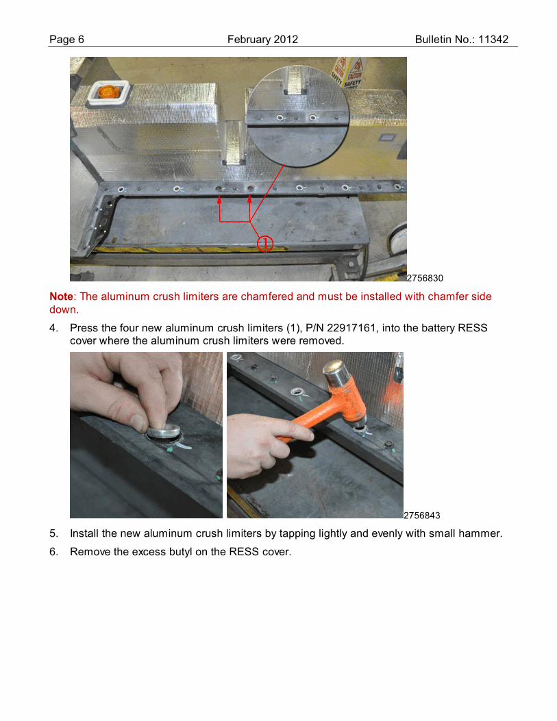
Note: The aluminum crush limiters are chamfered and must be installed with chamfer side down.
4. Press the four new aluminum crush limiters (1), P/N 22917161, into the battery RESS cover where the aluminum crush limiters were removed.
2756843
5. Install the new aluminum crush limiters by tapping lightly and evenly with small hammer.
6. Remove the excess butyl on the RESS cover.

Page 7 February 2012 Bulletin No.: 11342
2756855
7. Attach the reinforcement assembly (1) to the car body using the four shorter M10 bolts from the kit. Tighten bolts to 25 Nm (19 lb-ft). Make sure the reinforcement assembly is centered from side to side within the tunnel of the vehicle body.
2756857
8. Locate the front and rear plates to the car body and hold in position using two hand clamps or “C” clamps. Make sure the front and rear plates are centered from side to side on the tunnel reinforcement of the vehicle body.

Page 8 February 2012 Bulletin No.: 11342
2756888
9. Center punch all of the holes in the plates and reinforcement assembly before drilling the 3mm (1/8 in) pilot holes.
Caution: To increase the useful life of the drill bit, drill the holes into the vehicle body at a low speed. The appropriate drill speed will allow the drill bit to cut into the metal efficiently. The drill bit will remove metal chips or metal shavings from the high strength steel quickly if the appropriate drill speed is used. Ensure the drill used at a low speed for steps 10-14.
10. Drill 3mm (1/8 in) pilot holes into the vehicle body through the 20 existing holes in the front and rear plates. The three lower holes per plate will also go through the reinforcement assembly.
11. Drill 6.75mm (17/64 in) holes through the 20 pilot holes.
12. Remove the clamps and the front and rear plates. Set aside the plates.
Caution: To avoid vehicle damage, place a drill stop on drill bits to ensure drill does NOT enter the vehicle beyond 19 mm (¾ in) in depth.
13. Drill 3mm (1/8 in) pilot holes into the vehicle body through the 28 existing holes in the reinforcement assembly. Do not allow the drill bit to enter the vehicle body beyond 19 mm (¾ in) in depth for the six upper holes on each side.

Page 9 February 2012 Bulletin No.: 11342
2756882
Caution: To avoid vehicle damage, place a drill stop on drill bits to ensure drill does NOT enter the vehicle beyond 19 mm (¾ in) in depth.
14. Drill 6.75mm (17/64 in) holes through the 28 pilot holes from step 13. Use a drill stop or otherwise do not allow the drill bit to enter the car body beyond 19 mm (3/4 in) in depth for the six upper holes on each side.
15. Remove the four M10 bolts and the reinforcement assembly from the vehicle body. Set aside the reinforcement assembly and the bolts.
16. Deburr all of the drilled holes in the front and rear plates, the reinforcement assembly, and the vehicle body. Remove any metal shavings from the surfaces of the front and rear plates, the reinforcement assembly, and the vehicle body.
17. Clean all mating surfaces of the front and rear plates, the reinforcement assembly, and the vehicle body using isopropyl (rubbing) alcohol and a clean, lint-free cloth. Allow the alcohol to dry.

Page 10 February 2012 Bulletin No.: 11342
2756863
Caution: Ensure the Pliogrip two-part polyurethane mix is uniform in color BEFORE applying it to the parts. Discard the first 25 mm (1 in) of the mix that is not uniform. The color of the polyurethane varies. The illustrations in this bulletin show the polyurethane mix in black or green. The Pliogrip two-part polyurethane has a 30-minute open time. The application of the Pliogrip two-part polyurethane and the assembly of the reinforcement assembly must be completed in 30 minutes.
18. Apply approximately 5mm (3/16 in) beads of Pliogrip two-part polyurethane, P/N 7770B220, in the patterns shown onto the reinforcement assembly and the front and rear plates. Use a new mixing and dispensing tip, and ensure that both components of the polyurethane are dispensing and mixing from the dispensing tip prior to applying the polyurethane to the parts.

Page 11 February 2012 Bulletin No.: 11342
2756814
19. Coat drill holes and exposed metal with Pliogrip, P/N 7770B220, two-part polyurethane using a brush as shown in illustration.
2756872
20. Re-attach the reinforcement assembly to the vehicle body using the four shorter M10 bolts (1). Tighten bolts to 25 Nm (19 lb-ft). Make sure the reinforcement assembly is centered from side to side within the tunnel of the vehicle body. Ensure that the 6.75mm (17/64 in) holes drilled into the reinforcement assembly are aligned.

Page 12 February 2012 Bulletin No.: 11342
2756876
Caution: To ensure the pop rivets are installed correctly, use two hand clamps or “C” clamps to hold the plates into position. Make sure the rear plate is pressed against the vehicle body in each location as each rivet is being installed.
21. Re-locate the rear plate and install the 7 pop rivets (2), P/N 11561547, through the upper 6.75mm (17/64 in) holes. Make sure the rear plate is pressed against the vehicle body in each location as each pop rivet is being installed.
22. Re-locate the front plate and install 7 pop rivets (2), P/N 11561547, through the upper 6.75mm (17/64 in) holes. Make sure the front plate is pressed against the vehicle body in each location as each pop rivet is being installed.
23. Install the remaining 28 pop rivets (2), P/N 11561547, through the 6.75mm (17/64 in) holes of the reinforcement assembly. Make sure the reinforcement assembly is pressed against the vehicle body in each location as each pop rivet is being installed.
Note: The six longer rivets (3), P/N 11569698 are to be located in bottom of the front and rear plates.
24. Install the six pop rivets (3), P/N 11569698, through the lower 6.75mm (17/64 in) holes that were also drilled through the reinforcement assembly. Ensure the plate is pressed against the reinforcement assembly in each location as each pop rivet is being installed.
25. Grind flush any pop rivet mandrels that did not break off flush with the rivet head.
26. Wipe off any excess polyurethane that squeezed out around the reinforcement assembly or around the front and rear plates.

Page 13 February 2012 Bulletin No.: 11342
2756891
27. Apply RTV, P/N 88864346 (or equivalent), on and around each of the six upper rivet heads along each side of the reinforcement assembly. The other rivet head locations do not require sealer.
Caution: Remove and discard the four short M10 bolts from the reinforcement assembly. Discard the M10 and M8 bolts removed from the high-voltage battery. The battery tunnel reinforcement kit, PN 22920448, contains new M8 and M10 bolts. Use the new bolts to install the high-voltage battery to avoid vehicle damage.
28. Remove the four M10 bolts from the reinforcement assembly. Discard the M10 bolts.
29. Re-install and re-connect the high voltage battery using the 18 new M10 bolts, P/N 11588740, and four new M8 bolts, P/N 11588724, from the kit. Refer to Drive Motor Battery Replacement and Shipping in SI.
30. Lower the vehicle. Refer to Lifting and Jacking the Vehicle in SI.
HV Battery/Inverter Surge Tank Replacement and Coolant Level Sensor Jumper Harness Installation 1. Remove battery reservoir cap from coolant surge tank.
2393887
2. Remove front compartment sight shield.

Page 14 February 2012 Bulletin No.: 11342
2757179
3. Remove windshield washer filler tube (1) by pulling up on it.
2417439
4. Remove radiator upper mounts (2).
2757064
Caution: Do NOT use a prybar or similar tool to move the radiator module rearward, or damage to the radiator module can result.
Note: If accessing the surge tank-to-fan shroud fasteners is difficult, remove the radiator upper crossbar to gain access to the fasteners.
5. Push condenser/radiator/fan/module rearward and remove the two coolant surge tank fasteners (1).

Page 15 February 2012 Bulletin No.: 11342
2757170
6. Empty the power inverter module cooling system reservoir using the Vac-N-Fill system with 152 mm (6 in) hose extension.
7. Clamp shut power inverter module cooling system reservoir hoses.
2757078
8. Disconnect all hoses for both reservoirs of the coolant surge tank. Remove the battery coolant pump inlet hose, battery coolant cooler outlet hose, battery radiator outlet hose and generator control module coolant tank hose.
9. Remove the coolant surge tank.
9.1 Remove engine/intake cover.

Page 16 February 2012 Bulletin No.: 11342
2756811
9.2 Remove A/C refrigerant pressure sensor connector (1).
9.3 Wiggle coolant surge tank out of engine compartment.
10. Install coolant level sensor jumper harness.
2757168
10.1 Unplug refrigerant temperature sensor (3).
10.2 Pull out the wire harness.
10.3 Unseat Christmas tree retainer (1).
10.4 Disconnect compressor connector (2).
10.5 Remove harness clip from hose (4).

Page 17 February 2012 Bulletin No.: 11342
2757140
10.6 Cut off the wires at the back of the refrigerant temperature sensor (1) connector and strip 13 mm (1/2 in) of insulation from the two wire ends (2).
2757114
10.7 Locate the coolant level sensor jumper from service kit 19260759 and strip 13 mm (1/2 in) of insulation from the two wire ends.

Page 18 February 2012 Bulletin No.: 11342
2757181
10.8 Crimp connect white and black wires on the new kit harness to the white/blue and black/violet wires respectively using the splice clip provided in the service kit. Refer to the instructions provided in the kit for proper procedure and tools.
2757184
10.9 Apply heat to the splice clip/heat shrink to seal it to the wire insulation. Proper tools must be used to protect the wire insulation from excess heat.
2757090
10.10 Install the new corrugated tube (1) that is provided in the service kit over the harness splice. The corrugated tube should overlap existing harness corrugated tube on both sides.

Page 19 February 2012 Bulletin No.: 11342
10.11 Completely wrap new corrugated tube with black electrical tape.
10.12 Reinstall the wire harness.
10.13 Install harness clip on hose in specified area.
10.14 Replug the compressor connector.
10.15 Reseat the Christmas tree retainer (replace if damaged).
2757177
10.16 Install new harness clip (from the kit) on the A/C line above existing harness clip.
2757130
10.17 Put a dime-sized dab of RTV, P/N 88864346, (or equivalent) over exposed refrigerant temperature sensor (1) to cover exposed terminals.

Page 20 February 2012 Bulletin No.: 11342
2757150
11. Install the new coolant surge tank.
12. Connect coolant level sensor to new coolant surge tank.
13. Reconnect all coolant surge tank hoses.
14. Push radiator toward the engine and secure the driver’s side (left) mount coolant surge tank fastener (1) by installing and tightening the one bolt.
15. Reconnect A/C refrigerant pressure sensor connector.
16. Remove manual clamp from power inverter module cooling system reservoir hoses.
Note: Vac-N-Fill equipment must be used along with proper coolant. The Power Electronics / Charging and Battery Cooling systems require a 50/50 mix of DEX-COOL® and de-ionized water. This mixture is available in a pre-mix with bitterant, P/N 12378390 USA, P/N10953456, Canada. The pre-mixed coolant is no longer available without the bitterant chemical. Refer to P/I #PIP4910.
17. Vac-N-Fill the power inverter module cooling system reservoir.
2757171
17.1 Use the VAC-N-FILL equipment without the 152 mm (6 in) hose extension.

Page 21 February 2012 Bulletin No.: 11342
17.2 Pull vacuum (at least 15 in Hg) for five (5) minutes.
17.3 Fill while under vacuum.
17.4 Remove reservoir overflow port cap.
17.5 Install overflow tubing and reservoir cap.
Note: Vac-N-Fill equipment must be used along with proper coolant. The Power Electronics / Charging and Battery Cooling systems require a 50/50 mix of DEX-COOL® and de-ionized water. This mixture is available in a pre-mix with bitterant, P/N 12378390 USA, P/N10953456, Canada. The pre-mixed coolant is no longer available without the bitterant chemical. Refer to P/I #PIP4910.
18. Vac-N-Fill the battery cooling system reservoir.
2757173
18.1 Use the VAC-N-FILL equipment without the 152 mm (6 in) hose extension.
18.2 Pull vacuum (at least 15 in Hg) for 5 minutes.
18.3 Fill while under vacuum.
18.4 Again pull vacuum (at least 15 in Hg) for 5 minutes.
18.5 Fill to top of reservoir.
18.6 Re-enable the high voltage battery. Refer to Drive Motor Battery Replacement and Shipping in SI.

Page 22 February 2012 Bulletin No.: 11342 Note: Do not attempt to order the calibration number from GM Customer Care and Aftersales. The calibration numbers required for this service procedure are programmed into control modules via a Multiple Diagnostic Interface (MDI) and TIS2WEB with the calibration update. When using the MDI for reprogramming, ensure that it is updated with the latest software version. Use TIS2WEB on or after 02/10/12 to obtain the calibration. If you cannot access the calibration, call the Techline Customer Support Center and it will be provided.
For step-by-step programming instructions, please refer to SI and the Techline Information System (TIS) terminal.
19. Verify that there is a battery charge of 12 to 15 volts. The battery must be able to maintain a charge during programming. Only use an approved Midtronics® PSC 550 Battery Maintainer (SPS Programming Support Tool EL-49642) or equivalent to maintain proper battery voltage during programming.
20. Reprogram the modules listed in step 20.3. Refer to SI and Service Programming System (SPS) documentation for programming instructions.
20.1 Connect the MDI to the vehicle. Connect the MDI to the programming terminal with a cable.
20.2 Select J2534 MDI and Reprogram ECU from the Select Diagnostic Tool and Programming Process screen.
Note: Ensure that the hood is open and turn the vehicle ON to Service Mode. The Service Mode can be attained by pressing and holding the power button for 5 to 8 seconds WITHOUT depressing the brake pedal. Make sure that the ICE does not come on during this process.
20.3 Determine module year of vehicle.
Note: For 2011 vehicles, ensure that the most recent version of field action bulletin 11137 has been completed BEFORE performing the programming event in this bulletin.
For 2011 model year vehicles, select SEQ Programming Sequence Battery Energy Control Module (K15) and Hybrid Powertrain Control Module 2 (K114B) from the Supported Controllers screen.
For 2012 model year vehicles, select Hybrid Powertrain Control Module 2 (K114B) from the Supported Controllers screen.
20.4 Follow the on-screen instructions.

Page 23 February 2012 Bulletin No.: 11342 Caution: The Coolant level will drop below reservoir during this process. If it does, do not break vacuum, but use the Vac-N-Fill equipment to fill the reservoir. Next, re-establish the 15 in Hg vacuum for the remainder of the fill procedure. You may have to fill the reservoir several times during this procedure to prevent a low coolant condition, which will induce air into the system. If at the end of the procedure, the fluid level is below the reservoir, fill the reservoir and repeat the MDI/GDS Hybrid/EV Battery Pack Coolant Pump Bleed Procedure. 21. Run MDI/GDS2 “Hybrid/EV Battery Pack Coolant Pump Bleed Procedure” test while
maintaining the 15 in Hg vacuum throughout the process. This procedure will take about an hour to complete.
21.1 Launch GDS2 and select Diagnostics.
21.2 Ensure information is accurate on the Vehicle Selection screen and then press ENTER.
21.3 Select Module Diagnostics and then press ENTER.
21.4 Select Hybrid Powertrain Control Module 2 and then press ENTER.
21.5 Select Control Function and then press ENTER.
21.6 Select Hybrid/EV Battery Pack Coolant Pump Bleed Procedure and then press ENTER.
21.7 Adjust (remove or add) coolant level to max fill line.
21.8 Install overflow tubing and reservoir cap.
22. Clear diagnostic codes (DTCs) if necessary.
23. Disconnect the low voltage battery charger.
24. Turn vehicle off.
2417439
25. Reinstall radiator mounts (2). Tighten bolts to 22 Nm (16 lb-ft).

Page 24 February 2012 Bulletin No.: 11342
2757179
26. Reinstall windshield washer filler tube (1).
27. Reinstall engine/intake cover.
28. Road test the vehicle in Mountain Mode with the vehicle in Low Gear for approximately 5 miles (8 km). When performing the 5 mile (8 km) mile drive cycle, drive vehicle in slalom (side to side motion) to purge any remaining air.
2770855
29. Re-check coolant level. Ensure the coolant level is to the top of the tank seam (1).

Page 25 February 2012 Bulletin No.: 11342
2757164
30. Install locking bracket (1) on vehicle right side reservoir securing the bracket and the reservoir with the bolt provided in the kit. Tighten bolt from front side of tie bar.
2393887
31. Reinstall front compartment sight shield.
32. Wash the vehicle.
33. Fill the fuel tank.
34. Check tire pressure. Add air to tires if required.
35. Fully charge the high-voltage battery before returning the vehicle to the customer. COURTESY TRANSPORTATION – For US and Canada The General Motors Courtesy Transportation program is intended to minimize customer inconvenience when a vehicle requires a repair that is covered by the New Vehicle Limited Warranties. The availability of courtesy transportation to customers whose vehicles are within the warranty coverage period and involved in a product program is very important in maintaining customer satisfaction. Dealers are to ensure that these customers understand that shuttle service or some other form of courtesy transportation is available and will be provided at no charge. Dealers should refer to the General Motors Service Policies and Procedures Manual for Courtesy Transportation guidelines.

Page 26 February 2012 Bulletin No.: 11342 WARRANTY TRANSACTION INFORMATION Submit a transaction using the table below.
Labor Code Description
Labor Time
Net Item
V2533 Install Battery Reinforcement Brkt, Coolant Sensor, Coolant Tank 7.0 * T5848 Battery Charge, Tire Inflate, Vehicle Wash, & if applicable, Fill
Tank 0.7 **
* Submit the cost of the adhesive required to perform the repair, not to exceed $29.70 USD, $32.60 CAD, plus shipping.
** Submit the cost to fill the fuel tank in the Misc field. CUSTOMER NOTIFICATION – For US and Canada General Motors will notify customers of this program on their vehicle (see copy of customer letter included with this bulletin). CUSTOMER NOTIFICATION – For Export
Letters will be sent to known owners of record located within areas covered by the US National Traffic and Motor Vehicle Safety Act. For owners outside these areas, dealers should notify customers using the attached sample letter. DEALER PROGRAM RESPONSIBILITY All unsold new vehicles in dealers' possession and subject to this program must be held and inspected/repaired per the service procedure of this program bulletin before customers take possession of these vehicles. Dealers are to service all vehicles subject to this program at no charge to customers, regardless of mileage, age of vehicle, or ownership, from this time forward. Customers who have recently purchased vehicles sold from your vehicle inventory, and for which there is no customer information indicated on the involved vehicle listing, are to be contacted by the dealer. Arrangements are to be made to make the required correction according to the instructions contained in this bulletin. A copy of the customer letter is provided in this bulletin for your use in contacting customers. Program follow-up cards should not be used for this purpose, since the customer may not as yet have received the notification letter. In summary, whenever a vehicle subject to this program enters your vehicle inventory, or is in your facility for service in the future, you must take the steps necessary to be sure the program correction has been made before selling or releasing the vehicle.
GM bulletins are intended for use by professional technicians, NOT a "do-it-yourselfer". They are written to inform these technicians of conditions that may occur on some vehicles, or to provide information that could assist in the proper service of a vehicle. Properly trained technicians have the tools, equipment, safety instructions, and know-how to do a job properly and safely. If a condition is described, DO NOT assume that the bulletin applies to your vehicle, or that your vehicle will have that condition. See your dealer for information on whether your vehicle may benefit from the information.
We Support Voluntary
Technician Certification

Page 27 February 2012 Bulletin No.: 11342
(Letter for customers with 2011 MY vehicles - US Only)
February 2012 Dear Volt Customer: GM is now ready to implement the Volt vehicle enhancements that you were informed of in January. We will be making enhancements to the battery coolant system and vehicle structure. Specifically, your Chevrolet dealer will add a reinforcement bracket to further protect the battery pack in a severe side collision, replace the battery coolant system reservoir with a new reservoir that includes a sensor to monitor the coolant level, reprogram the high voltage battery diagnostic module to allow for low coolant sensing, and add a tamper-resistant bracket to the top of the battery coolant reservoir to help prevent potential coolant overfills. This service will be performed at no charge. In the fall of 2011, a software update was made available to you through Customer Satisfaction Program 11137. This updated software is required to perform the service above. If your vehicle does not already have this updated software, it will be installed for you at the same time, again, at no charge. Your vehicle's estimated electric vehicle range displayed in the instrument cluster will be reset. This will not affect your actual electric vehicle range. Within a short period of time, the displayed electric vehicle range will adjust to reflect an estimate more consistent with your normal driving range. We recommend that you contact your dealer at your convenience to schedule an appointment on or after March 19. Upon request, your dealer will also provide you with courtesy transportation while your vehicle is at the dealership. If you have any questions that your dealer is unable to answer, please contact your Volt advisor. The contact information is 877-4-VOLT-INFO (877-486-5846) or [email protected]. We want you to know that we will do our best, throughout your ownership experience, to ensure that your Chevrolet Volt provides you many miles of enjoyable driving. Alicia Boler-Davis U.S. Vice President Customer Experience 11342-1

Page 28 February 2012 Bulletin No.: 11342
(Letter for customers with 2012 MY vehicles - US & Canada Only)
February 2012 Dear Volt Customer: GM is now ready to implement the Volt vehicle enhancements that you were informed of in January. We will be making enhancements to the battery coolant system and vehicle structure. Specifically, your Chevrolet dealer will add a reinforcement bracket to further protect the battery pack in a severe side collision, replace the battery coolant system reservoir with a new reservoir that includes a sensor to monitor the coolant level, reprogram the high voltage battery diagnostic module to allow for low coolant sensing, and add a tamper-resistant bracket to the top of the battery coolant reservoir to help prevent potential coolant overfills. This service will be performed at no charge. Your vehicle's estimated electric vehicle range displayed in the instrument cluster will be reset. This will not affect your actual electric vehicle range. Within a short period of time, the displayed electric vehicle range will adjust to reflect an estimate more consistent with your normal driving range. We recommend that you contact your dealer at your convenience to schedule an appointment on or after March 19. Upon request, your dealer will also provide you with courtesy transportation while your vehicle is at the dealership. If you have any questions that your dealer is unable to answer, please contact your Volt advisor. The contact information is 877-4-VOLT-INFO (877-486-5846) or [email protected]. We want you to know that we will do our best, throughout your ownership experience, to ensure that your Chevrolet Volt provides you many miles of enjoyable driving. 11342-2 Alicia Boler-Davis U.S. Vice President Customer Experience


