shift-sliding and depth-pop for 3d positioningws.iat.sfu.ca/papers/depthpop.pdfshift-sliding and...
TRANSCRIPT
SHIFT-Sliding and DEPTH-POP for 3D PositioningJunwei Sun, Wolfgang Stuerzlinger
School of Interactive Arts + Technology Simon Fraser University, Vancouver, Canada [email protected], http://ws.iat.sfu.ca
Dmitri Shuralyov Department of EECS
York University, Toronto, Canada [email protected]
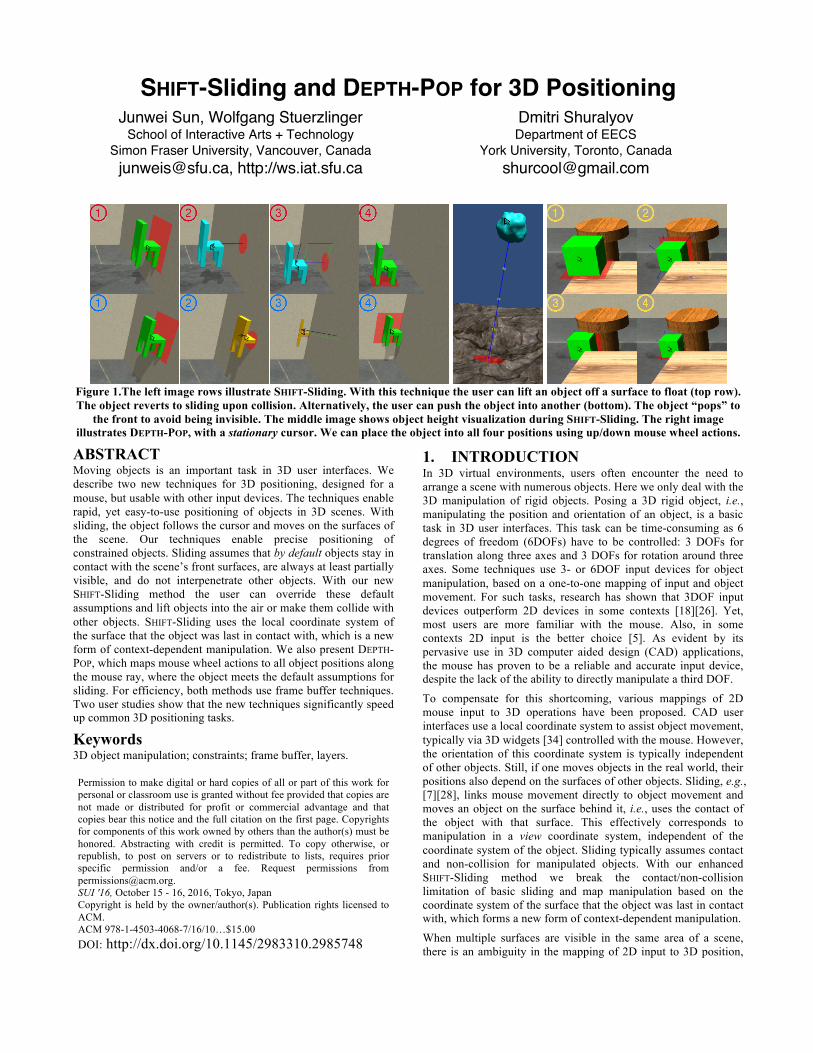
Figure 1.The left image rows illustrate SHIFT-Sliding. With this technique the user can lift an object off a surface to float (top row). The object reverts to sliding upon collision. Alternatively, the user can push the object into another (bottom). The object “pops” to
the front to avoid being invisible. The middle image shows object height visualization during SHIFT-Sliding. The right image illustrates DEPTH-POP, with a stationary cursor. We can place the object into all four positions using up/down mouse wheel actions.
ABSTRACT Moving objects is an important task in 3D user interfaces. We describe two new techniques for 3D positioning, designed for a mouse, but usable with other input devices. The techniques enable rapid, yet easy-to-use positioning of objects in 3D scenes. With sliding, the object follows the cursor and moves on the surfaces of the scene. Our techniques enable precise positioning of constrained objects. Sliding assumes that by default objects stay in contact with the scene’s front surfaces, are always at least partially visible, and do not interpenetrate other objects. With our new SHIFT-Sliding method the user can override these default assumptions and lift objects into the air or make them collide with other objects. SHIFT-Sliding uses the local coordinate system of the surface that the object was last in contact with, which is a new form of context-dependent manipulation. We also present DEPTH-POP, which maps mouse wheel actions to all object positions along the mouse ray, where the object meets the default assumptions for sliding. For efficiency, both methods use frame buffer techniques. Two user studies show that the new techniques significantly speed up common 3D positioning tasks.
Keywords 3D object manipulation; constraints; frame buffer, layers.
1. INTRODUCTION In 3D virtual environments, users often encounter the need to arrange a scene with numerous objects. Here we only deal with the 3D manipulation of rigid objects. Posing a 3D rigid object, i.e., manipulating the position and orientation of an object, is a basic task in 3D user interfaces. This task can be time-consuming as 6 degrees of freedom (6DOFs) have to be controlled: 3 DOFs for translation along three axes and 3 DOFs for rotation around three axes. Some techniques use 3- or 6DOF input devices for object manipulation, based on a one-to-one mapping of input and object movement. For such tasks, research has shown that 3DOF input devices outperform 2D devices in some contexts [18][26]. Yet, most users are more familiar with the mouse. Also, in some contexts 2D input is the better choice [5]. As evident by its pervasive use in 3D computer aided design (CAD) applications, the mouse has proven to be a reliable and accurate input device, despite the lack of the ability to directly manipulate a third DOF.
To compensate for this shortcoming, various mappings of 2D mouse input to 3D operations have been proposed. CAD user interfaces use a local coordinate system to assist object movement, typically via 3D widgets [34] controlled with the mouse. However, the orientation of this coordinate system is typically independent of other objects. Still, if one moves objects in the real world, their positions also depend on the surfaces of other objects. Sliding, e.g., [7][28], links mouse movement directly to object movement and moves an object on the surface behind it, i.e., uses the contact of the object with that surface. This effectively corresponds to manipulation in a view coordinate system, independent of the coordinate system of the object. Sliding typically assumes contact and non-collision for manipulated objects. With our enhanced SHIFT-Sliding method we break the contact/non-collision limitation of basic sliding and map manipulation based on the coordinate system of the surface that the object was last in contact with, which forms a new form of context-dependent manipulation.
When multiple surfaces are visible in the same area of a scene, there is an ambiguity in the mapping of 2D input to 3D position,
Permission to make digital or hard copies of all or part of this work for personal or classroom use is granted without fee provided that copies are not made or distributed for profit or commercial advantage and that copies bear this notice and the full citation on the first page. Copyrights for components of this work owned by others than the author(s) must be honored. Abstracting with credit is permitted. To copy otherwise, or republish, to post on servers or to redistribute to lists, requires prior specific permission and/or a fee. Request permissions from [email protected]. SUI '16, October 15 - 16, 2016, Tokyo, Japan Copyright is held by the owner/author(s). Publication rights licensed to ACM. ACM 978-1-4503-4068-7/16/10…$15.00 DOI: http://dx.doi.org/10.1145/2983310.2985748

2
e.g., as the manipulated object could be placed on the table or the floor visible behind it. To address this ambiguity, we introduce a new DEPTH-POP method, which enables efficient control of object position in depth. For this, we map discrete mouse wheel actions to object movement in depth, which puts the object at all those positions along the mouse ray, where contact and non-collision assumptions are met.
We first review relevant previous object manipulation work. Then we discuss the overall design space and introduce our new interaction methods. In the following, we present implementation details and describe our user studies. Finally, we discuss the results and mention potential future work.
2. RELATED WORK There has been substantial research in the field of object manipulation in 3D user interfaces.
Many mappings of 3- or 6DOF input device movements to object manipulation have been proposed. Ware et al. [41] introduced the bat, a 6DOF device with a natural one-to-one mapping. Hachet et al. [12] introduced the 6DOF Control Action Table, designed for immersive large display environments. The GlobeFish and GlobeMouse techniques [9] used a 3DOF trackball for 3D manipulation. Bérard et al. [5] compared the mouse with three 3DOF input devices in a 3D placement task and identified the mouse superior for accurate placement. Vuibert et al. [40] compared contactless mid-air manipulation with a Phantom and found mid-air manipulation faster but less accurate. Masliah et al. [25] studied the allocation of control in 6DOF docking and identified that rotational and translational DOFs are controlled separately. All techniques mentioned in this paragraph require 3D input devices, which currently do not afford the level of accuracy and precision of a modern mouse.
Many touch-based 3D manipulation techniques have been developed. Hancock et al.’s [13] multi-touch techniques provide 3D interaction within limited depth. Rotate’ N Translate (RNT) [22] offers integrated control of translation and rotation through a single touch-point. Reisman et al. [30] presented a screen-space method that provides direct 2D and 3D control. Martinet et al. [23] proposed two multi-touch techniques. Users preferred the Z-technique, which permits depth positioning. A later improvement separated translation and rotation [24]. Herrlich et al. [16] presented two techniques that integrate translation and rotation. Au et al. [1] presented a set of multi-touch gestures for constrained 3D manipulation. In general, the input mappings for touch-based 3D methods require learning and do not support accurate manipulation.
Another approach to 3D manipulation is based on widgets [8][34], which encapsulate 3D geometry and behavior. Such widgets are now prevalent in 3D CAD software. Mine et al. [27] presented hand-held widgets, i.e., 3D objects with geometry and behavior that appear in the user's virtual hand. Schmidt et al. [32] presented a system that automatically aligned widgets to axes and planes determined by a users’ stroke.
Some 3D manipulation systems use 2D input devices, typically the mouse. Bier [6] proposed snap-dragging, which snaps the 3D cursor to object features close to the cursor using a gravity function. Van Emmerik [37] proposed a technique where the user can perform 3D transformations in a local coordinate system through control points. Venolia [38] presented “tail-dragging”, where the user drags an object as it were attached to a rope. With a “snap-to” functionality, other objects also attract the manipulated object. Kitamura et al. [21] proposed a “magnetic metaphor” for
object manipulation, which aims to simulate physical behaviors, including non-penetration. In most of these techniques, the local coordinate system for object movement must be explicitly controlled by the user.
Building on Object Associations [7], Oh et al. [28] presented a sliding algorithm, where the object follows the cursor position directly and slides on any surface behind it, i.e., the moving object always stays attached to other objects. This form of sliding creates associations automatically, and these associations are not limited to predefined horizontally or vertically aligned surfaces. Compared to click-to-place methods, e.g., [7], sliding provides better visual feedback as the result of a (potential) placement is continuously visible. For targets in contact, Oh et al. compared sliding with axis-widgets and found that sliding is significantly more efficient for novices. Yet, Oh et al.’s sliding method lacks direct access to object movement in the third DOF. The authors identified that for some tasks users have to slide an object on a sequence of surfaces to reach a desired “layer” in depth, which is not always easy to understand, see Figure 3.
2.1 Contributions The main contributions we present here are:
• SHIFT-Sliding, which generalizes sliding to support floating and interpenetrating objects.
• A new method to map 2D input to 3D object translation based on the coordinate system of the surface that the object was last in contact with.
• A new DEPTH-POP interaction method that addresses the inherent depth ambiguity in sliding algorithms.
• Comparative evaluations of the new techniques.
3. SYSTEM AND INTERACTION DESIGN In this section, we discuss the fundamental assumptions that our new object manipulation techniques build on. We target novice users without CAD knowledge. We focus on a desktop-based user interface with a mouse and a keyboard, as this provides high performance in both speed and accuracy. A mouse also helps to keep our system easy to learn and use by novices, as many are used to this interaction device. Yet, the interaction for DEPTH-POP and SHIFT-Sliding is so simple and direct, that it could even be applied to touchscreens, as mentioned in the discussion section.
3.1 Design Assumptions We use a single perspective view, as this corresponds best to how novices are usually presented with 3D content [42]. We do not use stereo, as perspective and occlusion are usually sufficient to accurately judge an object’s 3D position and visibility [39]. In our system, we assume that objects are by default in contact with other objects and do not interpenetrate them. Moreover, we choose not to enable manipulation of objects when they are invisible. Here, we detail the reasoning behind our design assumptions.
1) The manipulated object stays by default in contact with the rest of the scene. As recognized by Teather et al. [36] and Stuerzlinger et al. [35], floating objects are exceptional on our planet, as (almost) all objects are in contact with other objects in the real world. Also, the exact position of a floating object is harder to perceive accurately, as there are fewer references to judge against. Such objects are also harder to manipulate because more DOFs need to be controlled [20]. In the default sliding mode of our system, whenever an object would float, we automatically put the object back into contact with the first surface behind it. With our new SHIFT-Sliding method, we enable the user to override this.

3
When there is nothing behind an object, it will slide parallel to the screen until something appears behind it.
2) The manipulated object does not interpenetrate the scene by default. In the real world, objects do not interpenetrate each other without explicit actions, such as drilling a hole. To avoid unwanted collisions, we choose to avoid interpenetration by default. When needed, we permit the user to force an object “into” another with SHIFT-Sliding. 3) The manipulated object is always at least partially visible to the user. Without other forms of feedback (such as haptics) an invisible object cannot be manipulated with precision with normal input devices. Moreover, a common issue in many 3D systems is that an object can become “lost” behind or inside other objects, which then forces the user to “find” it again through navigation. In our system and whenever an object would become completely invisible, we automatically bring the object to a position where it is visible.
When the user selects an object and manipulates it with standard sliding, the object will always remain in positions (and poses) where all three assumptions are met. Beyond the three scene-related assumptions above, we also assume that the scene is rendered as filled polygons. A wireframe representation of objects introduces ambiguities, as it does not explicitly define the enclosed surfaces. This is often difficult to understand for novices. Similarly, we also exclude volumetric content, such as a 3D brain scan.
3.2 Basic Sliding Sliding [28] maps object movement so that the manipulated object moves along the surface behind it that it is currently in contact with. We use the normal vector at the contact point to determine the sliding plane. With this contact constraint, we can directly map 2D motions of the mouse cursor to 3D movement of the object. Figure 2 illustrates sliding. When the user selects an object (at position A), we record the intersection of the mouse ray on the object as the start point. We identify the normal vector at the contact point on surface 1 via the frame buffer. The start point and the normal vector define the sliding plane. The intersection of a new mouse ray and the sliding plane becomes the end point of the object translation. By moving the mouse cursor, the user then effectively translates the object parallel to the sliding plane. We examine the situation with multiple contacts in different planes in the discussion section.
When the user slides the object to position B in Figure 2, any further upwards movement would cause the object to float. Here, basic sliding snaps the object back to the next surface behind it, to position C on surface 2, while keeping the object under the mouse cursor. The new contact point provides a new normal vector for a new sliding plane. Then the user can slide the object on surface 2, to positions such as D. If the user now moves the mouse back down, the object can reach position E, where it is still partially visible from the camera. Yet, if the user slides the object from E further downwards, the object would become invisible to the user. Here, we “pop” the object to the front, i.e., bring it to a position below (and a bit to the left of) B, in contact with surface 1. With this method we keep the mouse cursor at the same point on the object throughout, as an additional cue for object position, giving the user also a better understanding of the 3D object movement. To highlight the fact that the object is in contact, we render a semi-transparent rectangle at the contact surface.
Figure 2. Illustration of sliding movements for an object across
the front surfaces of two objects with an upwards mouse movement (positions A-D). The shaded part of surface 2 is
occluded by surface 1. Position E can only be reached from C with a downwards mouse movement. Positions F and G cannot
be reached from the current viewpoint, see text. When dragging an object along a surface nearly aligned with the view direction close to the horizon, it can easily disappear into the distance, since a small mouse movement can cause a dramatic object movement in 3D. To deal with this, we perform an occlusion test for every frame and bring the object to the front whenever it becomes completely invisible — even if this causes the object to slide on another surface. When there is no surface behind the object, we keep the object sliding parallel to the screen and inside the camera frustum (even if the projection of the object is very small). With this, the user can never lose sight of the moving object.
In our system, the user can slide objects on invisible surfaces, such as a portion of the surface 2 in Figure 2 that is hidden by surface 1 (near E). To keep the interaction intuitive, we only permit sliding on surfaces facing the user. If we were to enable sliding on back-faces, this would create inappropriate mappings. Consider that the user slides from A to B with an upwards movement of the cursor along surface 1 in Figure 2. To reach position F, the cursor movement would then need to be mapped to a downwards motion of the mouse, which is indistinguishable from a movement back towards A. Thus, a better option is to snap the object to a position beyond surface 1 and slide the object on surface 2.
Object sliding maps mouse input to 3D object motions, which automatically defines an appropriate local movement plane. This also guarantees that the cursor and object always stay aligned, regardless of the surface involved. The new SHIFT-Sliding technique generalizes sliding to situations where objects float or interpenetrate. Our new DEPTH-POP technique gives the user discrete control over object depth relative to the camera with a contact assumption.
4. SHIFT-SLIDING Basic sliding keeps the object in contact with the scene and automatically chooses the local sliding plane for the object. For some use cases, such as 3D game design or animation, there are scenarios where some objects are floating. Imagine a car in an action sequence or a bouncing ball in a 3D game. Basic sliding cannot deal with those situations effectively. With SHIFT-Sliding, users can break the assumptions of contact or non-collision. We still pop the object to front if it would become invisible to ensure accurate manipulation and for consistency.

4
While manipulating an object, the user can move the object orthogonal to the sliding plane by pressing the SHIFT key. If the user then “pulls” the object away from the surface, this will cause the object to float, see Figure 1. When the user releases the SHIFT key (with the mouse button still held down), the object will then keep sliding on a plane defined by the initial normal vector. In this state, the floating check is temporarily disabled. To provide feedback, we highlight the moving object in a different color in SHIFT mode. When the floating object collides, we transition the object back into sliding mode and start sliding on the collider surface.
If the user lifts an object up and releases the mouse button, the object floats and is highlighted accordingly. While the object is still highlighted, the user can later “re-capture” the object with a click, is then back in SHIFT-sliding mode, and can move the object on the previous sliding plane. If a floating object is no longer highlighted, it will snap back to a surface when clicked and then start sliding. Alternatively, with another SHIFT-click, the user can move the object up or down orthogonal to the sliding plane. This is an improvement over Object Associations [7], where breaking an association leads only to a three-axis manipulation mode.
If the user “pushes” the object into a surface while pressing the SHIFT key, the object will interpenetrate that surface. When the user releases the SHIFT key, the object will then keep sliding on the plane defined by the original normal vector, inside the surface, still maintaining the visibility assumption. We temporarily disable the collision check for objects pushed into a surface.
Figure 3. With sliding one can move between the two object positions by following one of the blue mouse paths. For the
right path in the left image, the object snaps to the wall when leaving the table. With DEPTH-POP the user can directly
transition with a single mouse-wheel action, without moving the cursor.
5. DEPTH-POP Moving the object in the 3rd dimension with a 2D input device involves indirect mappings. With sliding, previous work has observed that users can move objects along the “shortest continuous path across visible surfaces,” through long mouse motions [28]. For example, in Figure 3 and to move an object from the wall to the table top, novices will typically slide the object along the wall, the table leg and then onto the table surface [28]. With DEPTH-POP, the user can accomplish the same result with a single mouse wheel action, which makes manipulation more direct. To achieve the same result, Object Associations [7] or other “click-to-place” algorithms require the user to first move the object away and then into the right place, which requires a minimum of two move operations.
Hinckley et al. [17] used discrete cycling to select multiple objects along a mouse ray, but did not use this for positioning an object in 3D. LayerPaint [10] permits drawing continuous strokes even on occluded regions in multi-layer scenes through automatic depth
determination. Igarashi et al. [19] presented layer swap, which allows the user to directly modify the depth order of the top two layers by clicking on a 3D layered object. They also presented layer-aware dragging. While dragging an object, the user can toggle between drag-over and drag-under modes with the SHIFT key and the system will adjust the object’s depth automatically. Extending these works, we map the choice of 3D object position to scroll wheel actions, whenever the user is dragging/sliding an object with the left button. More specifically, with each wheel action our new DEPTH-POP technique selects the next, respectively previous, element from the set of 3D positions along the mouse ray that match our assumptions (contact, non-collision, visible). We map front and back movement of the mouse wheel to “push-to-back” respectively “pop-to-front”. Together with sliding, this enables users to move objects in all three dimensions directly and independently.
5.1 Push-to-Back/Pop-to-Front Moving the mouse wheel away from/towards the user triggers a push-to-back/pop-to-front event, e.g., between position B and C in Figure 2. With push-to-back the object is moved to the next possible position further away from the camera that satisfies all three main design assumptions. For each pop-to-front event, the object is moved to the next position closer to the camera again maintaining the design assumptions. We also call pop-to-front whenever the object becomes completely occluded, i.e., invisible.
5.2 Audio Feedback For DEPTH-POP actions, we use different auditory cues to indicate a successful DEPTH-POP or a failed attempt to give the user feedback. Examples of infeasible actions are an object that is already the foremost visible object and thus cannot be pulled closer or an object to be pushed further away but with nothing behind it.
5.3 Orthographic vs. Perspective Projection We display the 3D scene in perspective and use that camera also for visibility detection. After all, when all pixels of the selected object are invisible, the user cannot see and manipulate it with precision. If our system detects this situation, we call pop-to-front.
When we move the object along the mouse ray to bring an object closer or further away we use an orthographic camera in the DEPTH-POP algorithm. This design decision makes a functional difference for the user, as it guarantees that the point on the selected object remains stable underneath the mouse cursor at all times, which yields a better interaction mapping. After all, if the cursor position on the object shifts/changes during sliding, object movement becomes less predictable, and thus less precise. See Figure 4. The DEPTH-POP algorithm (see the appendix) computes a distance in depth, which corresponds to the distance that the object should move along the mouse ray. If we were to use a perspective camera, the minimum difference in depth occurs along various rays (a different one for each pixel), rather than a specific direction. Thus the smallest perspective depth difference is different from the mouse ray direction, which in turn would violate the static cursor property. Orthographic projection does not suffer from this ambiguity. Also, linear movements in orthographic projection correspond better to how an object moves in 3D. Thus, we set up an orthographic camera in the direction of the mouse ray and use the frame buffer of this camera for all computations and DEPTH-POP.

5
Figure 4. Perspective vs. orthographic projection. In
orthographic projection, an object at position A will be popped to B where the minimum depth difference occurs (red
dashed line), keeping the cursor stable. In perspective, the smallest depth difference (blue dashed line) would move the
object to C, violating the static cursor property.
6. IMPLEMENTATION Here we discuss implementation details of our system. We built our system in the Unity game engine. We use a desktop computer with 3.5 GHz i7 processor, 16 GB of memory, and two NVIDIA GeForce GTX 560 SLI graphics cards. We use a mouse and a keyboard as input devices.
6.1 Frame Buffer vs. Geometry We exploit the computing power of GPUs and use the frame buffer for most of the computations. This also enables us to slide objects on more complex “surfaces”, including even point clouds with normal vectors. Geometry-based methods would suffer from decreased performance with complex objects and surfaces. To support non-convex geometries, we use depth peeling [4] to compute all depth values for the hidden layers of the scene. With depth peeling, each unique depth layer in the scene is extracted, and the layers are enumerated in depth-sorted order. As in other systems, a left mouse down selects the closest object along the mouse ray. We highlight the selected object with a different color during sliding.
6.2 Floating and Collision Checks When the user selects an object that is not in contact with a surface, or when an object slides off a surface, we need to push the object back to force it into contact with the scene. When the object collides with the scene, we pull the object front to resolve the collision.
After floating and/or collision is resolved, we slide the object as previously described. Our floating and collision checks guarantee that the object is always in contact with the scene, and that the sliding plane changes seamlessly.
Figure 5. During rotation, an object is always kept in contact with the surface. To ensure contact, we move the object in the direction of the (contact) normal vector to resolve floating and
collision situations.
6.3 Contact-Based Object Rotation We map 3D rotation around the objects’ center to the right mouse button with the two-axis valuator method [3] and wheel operation in this state to rotation in the 3rd dimension [33]. If the object is in contact at the start, we maintain all our design assumptions during rotation. If the object rotates to a pose where it would float or collide, we resolve it by moving the object in the direction of the normal vector of the (last known) contact. See Figure 5.
7. EVALUATION We first evaluated the technical performance of our system. The system runs stably at 60 fps for scenes with almost a million polygons. The user can slide objects on various surfaces, including concave surfaces and point clouds. For the scenes shown on the right in Figure 6, a single DEPTH-POP operation takes less than 20 ms. We conducted two user studies to evaluate our new techniques.
Figure 6. In the left image, the object slides on a point cloud.
On the right, the torus can be placed on or around any branch of the tree (assuming enough space to avoid collisions).
7.1 Evaluation of SHIFT-Sliding Oh et al. [28] had compared the Sliding algorithm against 3D widgets in an assembly task for in-contact conditions and found the sliding algorithm to be superior. Our new SHIFT-Sliding method extends basic sliding to support floating and colliding objects. We hypothesize that our new method will similarly outperform widget-based techniques for tasks where objects float or collide. To address a potential confound we disabled camera navigation in our study. To ensure internal validity, we also disabled object rotation and DEPTH-POP for this study.
In a pilot study we compared our sliding technique against widgets in various conditions, including single and four-view presentation. In the 3D widgets method, the user can drag either the three axes manipulators or the corresponding plane manipulators to move the object in one or two dimensions. For all situations where objects were in contact, we observed that our results matched the outcome of the previous evaluation of sliding [28]. Average sliding and widget times were significantly different (F1,11 = 91.92, p < 0.001) with 6.05 seconds, respectively 30.70, which matches the main result of Oh et al. [28]. Thus, we examine in our first user study only the manipulation of objects not in contact with the scene, i.e., floating objects.
7.2 User Study 1 For floating objects, widget-based manipulation is easier if the local coordinate system of the object aligns with the world system. This can affect performance substantially. Thus we investigate coordinate system alignment through task subsets in our study.
7.2.1 Apparatus & Participants We used the implementation described above to conduct this experiment. We recruited 12 (5 female) undergraduate and

6
graduate students from the local university population. We did not screen participants for 3D/gaming experience. Our participants had varying game expertise, with 58% being regular gamers and 42% playing games only rarely. There was a 5-minute training session before the study, which introduced participants to the techniques in a playground environment, but did not include any version of the experimental tasks.
Figure 7. Top: The SHS condition with four views. The one-view condition uses only the bottom left view in full screen. The transparently shown target pose is floating above the
floor. Bottom: The LCS condition with four views. The target position is around the pillar.
7.2.2 Experiment Design We designed a 3D object positioning experiment and asked participants to move an object to a target position in various scenes. When the user positioned the object in the target, we measured the completion time and relative distance from the ideal target position. We recorded all actions of each user. The experiment had a 2 (techniques) x 2 (displays) x 2 (alignment) design. The order of technique, display, and alignment conditions was counter-balanced to avoid learning effects. The first technique uses a 3-axis widget aligned to the local coordinate system of the object. We call this technique LCS. With LCS, the user can drag either the three axes or the corresponding planes to move the object, as in most 3D editing software. The second technique is our new SHIFT-Sliding algorithm. We call this technique SHS here for brevity. The first display condition used four views (one perspective and three orthogonal views), corresponding to the standard user interface in 3D editing software. The second
condition uses only a single perspective view. Figure 7 top shows the SHS condition with four views.
As discussed before, we designed our experiment to focus on floating objects. To investigate the effect of object alignment with the scene, the tasks were composed of two subsets, corresponding to aligned or rotated poses relative to the world coordinate system. The object orientations in the aligned condition were aligned with the three axes in the world coordinate systems. In the rotated condition, objects were rotated 45 degrees on all three axes relative to the world coordinate system. The effect of such object alignment had not been investigated in previous work. Each task condition had 5 trials, with different objects and scenes. The target positions were positioned so that movement along all three axes was necessary. On average the movement distance along each axis corresponded to a third of the viewport size (in the orthogonal views). Each user performed all trials in both two task conditions with all techniques and displays, corresponding to a total of 40 (5x2x4) trials for each user. We asked the participants to perform the tasks as quickly and as accurately as possible.
7.2.3 User Study Results We used linear mixed models (with repeated measures) to incorporate subject variability. A critical value α = 0.05 was used to assess significance. The results showed that SHS (M=33.31 seconds, SE=1.85) is significantly faster than the industry standard LCS (M=38.56, SE=1.88), OneView (M=31.37, SE=1.55) is significantly faster than FourView (M=40.50, SE=2.12), and the aligned condition (M=31.99, SE=1.71) is significantly faster than the rotated one (M=39.89, SE=2.00). See Table 1 and Figure 8. In terms of completion time, all interactions were significant: SHS-OneView is faster than SHS-FourView and LCS-OneView. SHS-rotated and LCS-aligned are both faster than LCS-rotated. FourView-aligned and OneView-rotated are both faster than FourView-rotated.
A Tukey-Kramer’s test shows that for aligned targets, SHS-OneView (M=25.58 seconds) is not significantly different from LCS-FourView (M=23.80). For rotated targets, SHS-OneView is significantly faster than all other combinations.
In terms of target distance, technique did not have a significant effect. FourView (M=0.065, SE=0.007) had a significantly smaller distance than OneView (M=0.220, SE=0.017). Alignment did not have a significant effect. There were no significant interactions on target distance.
Table 1. Linear mixed model analysis results for completion time and distance for study 1.
Source c2(1) time Sig c2(1) distance Sig Tech 4.73 * 0.30 ns View 14.32 *** 19.24 * Align 10.72 ** 0.56 ns Tech*View 4.41 * 1.30 ns Tech*Align 17.33 *** 0.01 ns View*Align 6.44 * 1.25 ns Tech*View*Align 15.60 *** 0.11 ns
ns/ms = not/marginally sig., *,**,*** = p<0.05,0.01,0.001.
Nine of 12 participants found SHS easy to use. Eight participants prefer the SHS technique over LCS. Additionally, we got very

7
positive feedback, see the discussion. Those who did not prefer SHS stated that the need to hold SHIFT down makes coordination slightly harder, but more practice might help.
Figure 8. Time and distance for study 1. Error bars show 95%
confidence intervals.
7.3 Evaluation of DEPTH-POP We performed another pilot to compare basic sliding with DEPTH-POP. Several participants aborted the study due to frustration with basic sliding which made results hard to interpret. In scenes with simple geometry, such as Figure 3, sliding “around” works reasonably well, once users figure this out. Yet, in scenes with small thin features such as Figure 6 right, moving the torus between depth layers is challenging, as one cannot rely on the object becoming invisible to pop the object to the front. One viable strategy is to purposefully force a collision to pop the object to the front; yet then it becomes impossible to place the torus around the branch again. An alternative way for placing it around the branch is to slide an object from the tip of a branch inwards, but none of our participants were able to figure this out. Thus we concluded that basic sliding is not suited for such scenes and did not evaluate it.
7.4 User Study 2 In our second study we evaluated the DEPTH-POP algorithm in isolation, for objects in contact with the scene. We hypothesize that with DEPTH-POP users would be able to complete tasks quicker than with a widget-based technique.
7.4.1 Apparatus & Participants We evaluated our implementation of DEPTH-POP in this experiment. We recruited 12 (5 female) different graduate and undergraduate students from the local university population. We did not screen participants for 3D/gaming experience. Our participants had varying game expertise, with 42% being regular gamers and 58% playing games only rarely. There was a five-minute training session before the study, which introduced participants to the techniques.
7.4.2 Experiment Design Similar to the first study, the experiment had a 2 (techniques) x 2 (displays) x 2 (alignment) design. The order of technique, display, and alignment conditions was counter-balanced to avoid learning effects. We used LCS again as the first technique. The second technique was SHIFT-Sliding with DEPTH-POP enabled, which we call SDP here. The display conditions were again four views and a single view. We also looked again at tasks with aligned and rotated poses. All tasks involved only objects in contact and could be achieved with basic sliding and DEPTH-POP, i.e., did not require SHIFT-Sliding. Still, we did not disable SHIFT-Sliding, as some tasks can indeed be completed with SHIFT-Sliding and the
automatic collision response of our system. We had again 5 trials for each object alignment condition. Each user had to perform 40 (5x2x4) trials. Figure 7 bottom shows the LCS condition with four views.
Table 2. Linear mixed model analysis results for completion time and distance for study 2.
Source c2(1) time Sig c2(1) distance Sig Tech 71.67 *** 8.80 ** View 7.37 ** 36.86 *** Align 56.83 *** 0.58 ns Tech*View 1.11 ns 9.55 ** Tech*Align 3.56 ms 0.03 ns View*Align 13.16 *** 1.77 ns Tech*View*Align 7.68 ** 0.20 ns
ns/ms = not/marginally sig., *,**,*** = p<0.05,0.01,0.001.
7.4.3 User Study Results The results of a linear mixed model (with repeated measures) analysis showed that SDP (M=17.55 seconds, SE=1.18) is significantly faster than LCS (M=31.85, SE=1.57), OneView (M=22.41, SE=1.24) is significantly faster than FourView (M=27.00, SE=1.64), and the aligned condition (M=18.33, SE=0.97) is significantly faster than the rotated condition (M=31.07, SE=1.73). In terms of completion time, the interaction between views and rotation was significant: FourView-aligned and OneView-rotated are both faster than FourView-rotated. See Table 2 and Figure 9.
In terms of target distance, SDP (M=0.057, SE=0.007) had a significantly smaller distance than LCS (M=0.095, SE=0.012). Moreover, FourView (M=0.037, SE=0.003) had significantly smaller distance than OneView (M=0.115, SE=0.014). Alignment did not have a significant effect. The interaction of technique and view had a significant effect. Both LCS-FourView and SDP-OneView had a significantly smaller distance than LCS-OneView. The other interactions were not significant.
Seven participants found the SDP technique easy to use and relied solely on DEPTH-POP to complete the tasks. A few participants found it harder to understand when to use DEPTH-POP, so they performed some of the trials with SHIFT-Sliding. They stated that with more practice they would use it more frequently.
Figure 9. Time and distance for study 2. Error bars show 95%
confidence intervals.

8
7.5 Improvements to 3D Object Position Visualization
Based on the feedback from the participants as well as our observations, we added some visualizations to our system to enhance the perception of 3D positions. Some users found it hard to judge the sliding plane and movement relative to the lift position in the floating state with SHIFT-Sliding. In DEPTH-POP, some users had issues with the idea that object movement is along the cursor ray. To address these issues, when an object is lifted up, we now draw a line with markers equal to the bounding box size (projected in the normal direction) to indicate height in SHIFT-Sliding, see Figure 1. When the user slides an object away from the initial lift position, we show additional lines in the local coordinate system that connect the object’s current and lift position, see Figure 7 top. This provides strong perspective cues, which further help the user to better judge the object’s position in 3D. To clearly indicate that an object floats, we replace the semi-transparent rectangle for contact visualization with a small circle. Unlike interactive shadows [15], this circle is not interactive. For push-to-back DEPTH-POP actions we also show (dark blue) guides to help the user understand the 3D movement better, see Figure 1.
8. DISCUSSION Sliding keeps the manipulated object by default in contact with the remainder of the scene. The assumption is true for most scenes in the real world, and thus facilitates object movement in many scenes. SHIFT-Sliding adds the new ability to have objects float or interpenetrate. Moreover, SHIFT-Sliding automatically derives a local coordinate system from the last known contact surface, which makes it easy to position objects in space relative to other objects, without having to explicitly set a local coordinate system. Results from the first study show that SHIFT-Sliding is easy to use and, for floating objects, 16% faster than the widget-based approach, the current industry standard. Together with Oh et al.’s results [28], this means that SHIFT-Sliding is globally faster than the widget-based method, regardless if the target position is in contact or not. Given the frequency of widget-based positioning in the 3D workflow, this means that SHIFT-Sliding can result in substantial time savings for practitioners. We got very positive feedback from the participants, where some even commented along the lines of: “I wish I had this in 3DS Max”. Moreover, SHIFT-Sliding in a single perspective view is never significantly worse than the widget-based approach. With SHIFT-Sliding, users received enough depth cues to complete the tasks in the single perspective view. They found it easy to find an appropriate plane to start sliding with the SHIFT key, even for complex surfaces. In fact, we observed that it does not matter that much where in a given 3D movement task users start to use the SHIFT key to lift the object. For rotated target poses, SHIFT-Sliding was at least 29% faster than any widget-based condition. Widget-based manipulation also suffered with rotated targets, as dragging in the (rotated) widget coordinate system causes movement in more than one direction in the world coordinate system, which is harder to understand for users. Thus, SHIFT-Sliding effectively merges the freedom of widget-based manipulation with the efficiency of sliding. This fundamentally improves 3D object manipulation with 2D input devices.
The second study shows that SHIFT-Sliding with DEPTH-POP is more efficient, 81% faster, and 67% more accurate than the widget-based technique, as it automatically determines valid object positions in depth. The (seemingly) simple mapping to mouse-wheel actions together with our accelerated
implementation greatly simplifies moving objects in depth and radically accelerates the associated tasks. DEPTH-POP facilitates even more challenging tasks, such as fitting a complex object around another one.
Results from both studies show that the OneView condition is on average more efficient than FourView, but less accurate. Based on our observations during the study, users might have tried to be more accurate with FourView display, at the expense of efficiency. Also, with widget-based manipulation, FourView was faster for aligned targets, yet OneView faster for rotated targets. We are not certain that this last finding holds up, as in the orthogonal views of the FourView widget condition a third of the axis controllers did not always work correctly with rotated objects in the study. While users were able to complete the tasks, we recognize that the faulty controllers may have had a limited negative effect for this specific condition. Yet, participants had experienced this issue in the training session and thus learned to use the other views and/or controllers. Moreover, based on our observations during the study, we believe that the impact of this issue was overshadowed by the fact that users struggled (much) more with the challenges posed by a locally rotated 3D coordinate system.
In both studies, the participants commented that more practice would help. It would be interesting to measure the learnability of our new methods in a long term study. To address potential issues around having to hold the SHIFT key down during SHIFT-Sliding, one option would be to use the SHIFT key similar to a toggle [19].
8.1 Other Reflections As there are only two interaction modes in our system, we can easily adapt our technique for a touchscreen interface. As is standard in most touch interfaces, the user can select and slide an object with a single finger. A second touch/hold can then serve as an activation event for SHIFT-Sliding to float an object. A flick of a second finger can be mapped to DEPTH-POP actions, depending on the direction of said flick. The second finger could be either a finger of the other hand or the same hand, as in recent work [31].
If the selected object has multiple contact points, the sliding behaviour depends on the contact points and their normal vectors. If the object slides across two identical table surfaces that are positioned side-by-side, the normal vectors and contact planes are the same. Thus the object can smoothly slide from one table to the other. If the object slides on a table surface towards a wall, the normal vector for the new contact will be different. In this case, the object would collide and we pop the object to the front (of the wall). Then, it will slide on the wall. Previous work, e.g., [28], has already shown that multiple (compatible) contacts can be used to slide an object.
In our system users control translational and rotational DOFs separately during manipulation [25]. We choose to keep object orientation static during sliding. Alternatively, we could also dynamically change the objects’ orientation with the normal vector of the sliding plane, thus keeping the same surface of the manipulated object in contact with the scene. This could be provided as a separated mode.
Ayatsuka et al. [2] already identified that manipulation via interactive shadows is unnatural, since three projections are needed. Yet, their penumbrae method [2] has also the drawback that penumbrae scale non-linearly with object height. The shadows in our system are not interactive. In the work of Glueck et al. [11], the shaded inner region of the base coarsely indicates the height of objects. Yet, as reported by Heer et al. [14], circular area

9
judgments are not that accurate. The length of their “stalks” shows object heights directly – but is still perspectively foreshortened. We instead show markers at regular intervals to facilitate quick perception of object height.
As mentioned before, we disable back-face sliding. Yet, we could also temporarily enable such sliding in our system in some situations. One potential scenario is to permit the user to put an object in contact with a back surface with DEPTH-POP and slide along it. This would not cause the inappropriate mapping issue discussed before. Whenever the object loses contact, i.e., starts floating or collides we would then transition to basic “front” sliding.
3D scanning a real scene yields point clouds. Converting such point clouds to geometry requires extra work. If the application scenario requires the user to place synthetic objects into a scanned scene, sliding can be used directly on the point clouds. For this, we only need normal vectors for each sample point. Then the contact point and sliding plane can potentially change at every frame during slides. SHIFT-Sliding also works on point clouds. However, DEPTH-POP only works if the samples form reasonably dense layers. With DEPTH-POP it is possible to place the object inside the “body” of a point cloud, i.e., locations where the normal vector of the contact point is pointing away from the user. To avoid this, it is better to limit sliding only to front-facing points. We accelerate most of the computations through the GPU. We use the frame buffer for most of the components in the system, including collision detection. For simplicity, we chose to use an image-based technique for identifying collisions, but any method, which provides information about the position, normal vector, and interpenetration distance where the collision occurs, suffices.
9. CONCLUSION We presented two novel 3D positioning techniques that are efficient and easy to use. We extend basic sliding with the new SHIFT-Sliding and DEPTH-POP methods. The results of the user studies showed that for novice users the new methods are more efficient for 3D positioning compared to the standard widget-based approach. Both methods profoundly enhance the ease and efficiency of 3D manipulation with 2D input devices.
In the future, we plan to explore if rendering front layers transparent can aid the manipulation of invisible objects, based on previous work [10][29]. Also, we intend to look at new methods for manipulation with multiple constraints.
The current implementation of DEPTH-POP can slow down in scenes with high depth complexity on lower-end graphics hardware. In scenes with many hidden layers, the large amount of small fragments could lead to a huge amount of solutions. Many of those solutions might be meaningless for interaction. In the future, we will optimize the algorithm to deal better with such cases through appropriate pruning.
10. ACKNOWLEDGMENTS We would like to thank all the participants.
11. REFERENCES [1] Au, O.K.C., Tai, C.L. and Fu, H., 2012, May. Multitouch
gestures for constrained transformation of 3d objects. In Computer Graphics Forum (Vol. 31, No. 2pt3, pp. 651-660). Blackwell Publishing Ltd.
[2] Ayatsuka, Y., Matsuoka, S. and Rekimoto, J., 1996, November. Penumbrae for 3D interactions. In Proceedings
of the 9th Annual ACM Symposium on User Interface Software and Technology (pp. 165-166). ACM.
[3] Bade, R., Ritter, F. and Preim, B., 2005, August. Usability comparison of mouse-based interaction techniques for predictable 3d rotation. In International Symposium on Smart Graphics (pp. 138-150). Springer Berlin Heidelberg.
[4] Bavoil, L. and Myers, K., 2008. Order independent transparency with dual depth peeling. NVIDIA OpenGL SDK, pp.1-12.
[5] Bérard, F., Ip, J., Benovoy, M., El-Shimy, D., Blum, J.R. and Cooperstock, J.R., 2009, August. Did “Minority Report” get it wrong? Superiority of the mouse over 3D input devices in a 3D placement task. In IFIP Conference on Human-Computer Interaction (pp. 400-414). Springer Berlin Heidelberg.
[6] Bier, E.A., 1990. Snap-dragging in three dimensions. ACM SIGGRAPH Computer Graphics, 24(2), pp.193-204.
[7] Bukowski, R.W. and Séquin, C.H., 1995, April. Object associations: a simple and practical approach to virtual 3D manipulation. In Proceedings of the 1995 Symposium on Interactive 3D graphics (pp. 131-ff). ACM.
[8] Conner, B.D., Snibbe, S.S., Herndon, K.P., Robbins, D.C., Zeleznik, R.C. and Van Dam, A., 1992, June. Three-dimensional widgets. In Proceedings of the 1992 Symposium on Interactive 3D Graphics (pp. 183-188). ACM.
[9] Froehlich, B., Hochstrate, J., Skuk, V. and Huckauf, A., 2006, April. The globefish and the globemouse: two new six degree of freedom input devices for graphics applications. In Proceedings of the SIGCHI Conference on Human Factors in Computing Systems (pp. 191-199). ACM.
[10] Fu, C.W., Xia, J. and He, Y., 2010, April. Layerpaint: a multi-layer interactive 3D painting interface. In Proceedings of the SIGCHI Conference on Human Factors in Computing Systems (pp. 811-820). ACM.
[11] Glueck, M., Crane, K., Anderson, S., Rutnik, A. and Khan, A., 2009, February. Multiscale 3D reference visualization. In Proceedings of the 2009 Symposium on Interactive 3D Graphics and Games (pp. 225-232). ACM.
[12] Hachet, M., Guitton, P. and Reuter, P., 2003, October. The CAT for efficient 2D and 3D interaction as an alternative to mouse adaptations. In Proceedings of the ACM Symposium on Virtual Reality Software and Technology (pp. 225-112). ACM.
[13] Hancock, M., Carpendale, S. and Cockburn, A., 2007, April. Shallow-depth 3d interaction: design and evaluation of one-, two-and three-touch techniques. In Proceedings of the SIGCHI Conference on Human Factors in Computing Systems (pp. 1147-1156). ACM.
[14] Heer, J. and Bostock, M., 2010, April. Crowdsourcing graphical perception: using mechanical turk to assess visualization design. In Proceedings of the SIGCHI Conference on Human Factors in Computing Systems (pp. 203-212). ACM.
[15] Herndon, K.P., Zeleznik, R.C., Robbins, D.C., Conner, D.B., Snibbe, S.S. and Van Dam, A., 1992, December. Interactive shadows. In Proceedings of the 5th Annual ACM Symposium on User Interface Software and Technology (pp. 1-6). ACM.

10
[16] Herrlich, M., Walther-Franks, B. and Malaka, R., 2011, July. Integrated rotation and translation for 3D manipulation on multi-touch interactive surfaces. In International Symposium on Smart Graphics (pp. 146-154). Springer Berlin Heidelberg.
[17] Hinckley, K., Pausch, R., Goble, J.C. and Kassell, N.F., 1994, November. A survey of design issues in spatial input. In Proceedings of the 7th Annual ACM Symposium on User Interface Software and Technology (pp. 213-222). ACM.
[18] Hinckley, K., Tullio, J., Pausch, R., Proffitt, D. and Kassell, N., 1997, October. Usability analysis of 3D rotation techniques. In Proceedings of the 10th Annual ACM Symposium on User Interface Software and Technology (pp. 1-10). ACM.
[19] Igarashi, T. and Mitani, J., 2010, July. Apparent layer operations for the manipulation of deformable objects. In ACM Transactions on Graphics (TOG) (Vol. 29, No. 4, p. 110). ACM.
[20] Jacob, R.J., Sibert, L.E., McFarlane, D.C. and Mullen Jr, M.P., 1994. Integrality and separability of input devices. ACM Transactions on Computer-Human Interaction (TOCHI), 1(1), pp.3-26.
[21] Kitamura, Y., Ogata, S. and Kishino, F., 2002, November. A manipulation environment of virtual and real objects using a magnetic metaphor. In Proceedings of the ACM Symposium on Virtual Reality Software and Technology (pp. 201-207). ACM.
[22] Kruger, R., Carpendale, S., Scott, S.D. and Tang, A., 2005, April. Fluid integration of rotation and translation. In Proceedings of the SIGCHI Conference on Human Factors in Computing Systems (pp. 601-610). ACM.
[23] Martinet, A., Casiez, G. and Grisoni, L., 2010, March. The design and evaluation of 3d positioning techniques for multi-touch displays. In 3D User Interfaces (3DUI), 2010 IEEE Symposium on (pp. 115-118). IEEE.
[24] Martinet, A., Casiez, G. and Grisoni, L., 2010, November. The effect of DOF separation in 3D manipulation tasks with multi-touch displays. In Proceedings of the 17th ACM Symposium on Virtual Reality Software and Technology (pp. 111-118). ACM.
[25] Masliah, M.R. and Milgram, P., 2000, April. Measuring the allocation of control in a 6 degree-of-freedom docking experiment. In Proceedings of the SIGCHI Conference on Human Factors in Computing Systems (pp. 25-32). ACM.
[26] McMahan, R.P., Gorton, D., Gresock, J., McConnell, W. and Bowman, D.A., 2006, November. Separating the effects of level of immersion and 3D interaction techniques. In Proceedings of the ACM Symposium on Virtual Reality Software and Technology (pp. 108-111). ACM.
[27] Mine, M.R., Brooks Jr, F.P. and Sequin, C.H., 1997, August. Moving objects in space: exploiting proprioception in virtual-environment interaction. In Proceedings of the 24th Annual Conference on Computer Graphics and Interactive Techniques (pp. 19-26). ACM Press/Addison-Wesley Publishing Co.
[28] Oh, J.Y. and Stuerzlinger, W., 2005, May. Moving objects with 2D input devices in CAD systems and desktop virtual environments. In Proceedings of Graphics Interface
2005 (pp. 195-202). Canadian Human-Computer Communications Society.
[29] Ortega, M. and Vincent, T., 2014, April. Direct drawing on 3D shapes with automated camera control. In Proceedings of the SIGCHI Conference on Human Factors in Computing Systems (pp. 2047-2050). ACM.
[30] Reisman, J.L., Davidson, P.L. and Han, J.Y., 2009, October. A screen-space formulation for 2D and 3D direct manipulation. In Proceedings of the 22nd Annual ACM Symposium on User Interface Software and Technology (pp. 69-78). ACM.
[31] Scheurich, D. and Stuerzlinger, W., 2013, September. A One-Handed Multi-Touch Method for 3D Rotations. In IFIP Conference on Human-Computer Interaction (pp. 56-69). Springer Berlin Heidelberg.
[32] Schmidt, R., Singh, K. and Balakrishnan, R., 2008, April. Sketching and composing widgets for 3d manipulation. In Computer Graphics Forum (Vol. 27, No. 2, pp. 301-310). Blackwell Publishing Ltd.
[33] Shuralyov, D. and Stuerzlinger, W., 2011. A 3D desktop puzzle assembly system. In Proceedings of the IEEE Symposium on 3D User Interfaces (3DUI), pp. 139-140. IEEE.
[34] Strauss, P.S. and Carey, R., 1992, July. An object-oriented 3D graphics toolkit. In ACM SIGGRAPH Computer Graphics (Vol. 26, No. 2, pp. 341-349). ACM.
[35] Stuerzlinger, W. and Wingrave, C.A., 2011. The value of constraints for 3D user interfaces. In Virtual Realities (pp. 203-223). Springer Vienna.
[36] Teather, R.J. and Stuerzlinger, W., 2007, November. Guidelines for 3D positioning techniques. In Proceedings of the 2007 Conference on Future Play (pp. 61-68). ACM.
[37] Van Emmerik, M.J., 1990, December. A direct manipulation technique for specifying 3D object transformations with a 2D input device. In Computer Graphics Forum (Vol. 9, No. 4, pp. 355-361). Blackwell Publishing Ltd.
[38] Venolia, D., 1993, May. Facile 3D direct manipulation. In Proceedings of the INTERACT'93 and CHI'93 Conference on Human Factors in Computing Systems (pp. 31-36). ACM.
[39] Vishton, P.M. and Cutting, J.E., 1995. Wayfinding, displacements, and mental maps: velocity fields are not typically used to determine one's aimpoint. Journal of Experimental Psychology: Human Perception and Performance, 21(5), p.978.
[40] Vuibert, V., Stuerzlinger, W. and Cooperstock, J.R., 2015, August. Evaluation of Docking Task Performance Using Mid-air Interaction Techniques. In Proceedings of the 3rd ACM Symposium on Spatial User Interaction (pp. 44-52). ACM.
[41] Ware, C. and Jessome, D.R., 1988. Using the bat: A six-dimensional mouse for object placement. Computer Graphics and Applications, IEEE, 8(6), pp.65-70.
[42] Wickens, C. and Hollands, J., 1999. Spatial displays. Engineering Psychology and Human Performance, Prentice-Hall, 3.
11
APPENDIX In this appendix, we describe the technical details of our new interaction methods, starting with several helper algorithms and implementation details.
Depth Intervals To enable DEPTH-POP, we first introduce a new algorithm based on depth intervals. The algorithm for depth intervals will output the optimal distance for the object to be pushed to the back or popped to the front. For simplicity of explanation, we focus our discussion here on convex objects and generalize the algorithm to concave cases later.
We use an orthographic view as this corresponds better to the way the object moves. First, we render the moving object twice to generate a depth buffer image for both the front and back-facing surface of the object, which defines the “thickness” of the selected object at each pixel. We limit the size of the 3D orthographic view frustum to the bounding volume of the object to maximize precision and minimize computation.
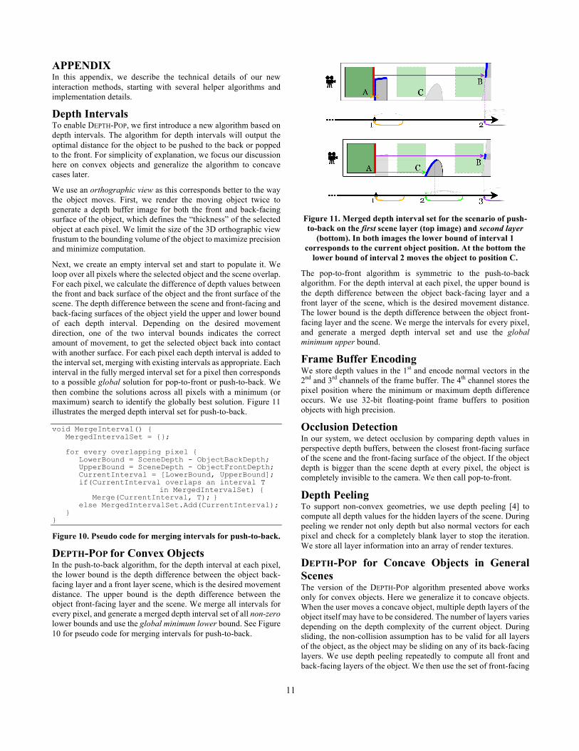
Next, we create an empty interval set and start to populate it. We loop over all pixels where the selected object and the scene overlap. For each pixel, we calculate the difference of depth values between the front and back surface of the object and the front surface of the scene. The depth difference between the scene and front-facing and back-facing surfaces of the object yield the upper and lower bound of each depth interval. Depending on the desired movement direction, one of the two interval bounds indicates the correct amount of movement, to get the selected object back into contact with another surface. For each pixel each depth interval is added to the interval set, merging with existing intervals as appropriate. Each interval in the fully merged interval set for a pixel then corresponds to a possible global solution for pop-to-front or push-to-back. We then combine the solutions across all pixels with a minimum (or maximum) search to identify the globally best solution. Figure 11 illustrates the merged depth interval set for push-to-back.
void MergeInterval() { MergedIntervalSet = {}; for every overlapping pixel { LowerBound = SceneDepth - ObjectBackDepth; UpperBound = SceneDepth - ObjectFrontDepth; CurrentInterval = [LowerBound, UpperBound]; if(CurrentInterval overlaps an interval T in MergedIntervalSet) { Merge(CurrentInterval, T); } else MergedIntervalSet.Add(CurrentInterval); } }
Figure 10. Pseudo code for merging intervals for push-to-back.
DEPTH-POP for Convex Objects In the push-to-back algorithm, for the depth interval at each pixel, the lower bound is the depth difference between the object back-facing layer and a front layer scene, which is the desired movement distance. The upper bound is the depth difference between the object front-facing layer and the scene. We merge all intervals for every pixel, and generate a merged depth interval set of all non-zero lower bounds and use the global minimum lower bound. See Figure 10 for pseudo code for merging intervals for push-to-back.
Figure 11. Merged depth interval set for the scenario of push-to-back on the first scene layer (top image) and second layer
(bottom). In both images the lower bound of interval 1 corresponds to the current object position. At the bottom the
lower bound of interval 2 moves the object to position C.
The pop-to-front algorithm is symmetric to the push-to-back algorithm. For the depth interval at each pixel, the upper bound is the depth difference between the object back-facing layer and a front layer of the scene, which is the desired movement distance. The lower bound is the depth difference between the object front-facing layer and the scene. We merge the intervals for every pixel, and generate a merged depth interval set and use the global minimum upper bound.
Frame Buffer Encoding We store depth values in the 1st and encode normal vectors in the 2nd and 3rd channels of the frame buffer. The 4th channel stores the pixel position where the minimum or maximum depth difference occurs. We use 32-bit floating-point frame buffers to position objects with high precision.
Occlusion Detection In our system, we detect occlusion by comparing depth values in perspective depth buffers, between the closest front-facing surface of the scene and the front-facing surface of the object. If the object depth is bigger than the scene depth at every pixel, the object is completely invisible to the camera. We then call pop-to-front.
Depth Peeling To support non-convex geometries, we use depth peeling [4] to compute all depth values for the hidden layers of the scene. During peeling we render not only depth but also normal vectors for each pixel and check for a completely blank layer to stop the iteration. We store all layer information into an array of render textures.
DEPTH-POP for Concave Objects in General Scenes The version of the DEPTH-POP algorithm presented above works only for convex objects. Here we generalize it to concave objects. When the user moves a concave object, multiple depth layers of the object itself may have to be considered. The number of layers varies depending on the depth complexity of the current object. During sliding, the non-collision assumption has to be valid for all layers of the object, as the object may be sliding on any of its back-facing layers. We use depth peeling repeatedly to compute all front and back-facing layers of the object. We then use the set of front-facing

12
and back-facing depth layers to define the object’s position and movement.
Here we discuss the generalization of the DEPTH-POP algorithm for non-convex objects and scenes. For each layer from the object and each layer of the scene, we use the depth intervals to obtain a solution for the moving distance. Each solution guarantees that a part of the concave object will be in contact with a layer of the scene, after moving the object by that distance. We gather all non-zero solutions and sort them in ascending order. We then identify the smallest moving distance that we can move the object without causing a collision. For this, we validate all potential solutions: Starting from the smallest moving distance, we examine if there would be collision if we move the object by that distance and iterate until we find a valid solution. Then we move the object by the corresponding distance. Otherwise we report failure. Figure 12 shows the pseudo code for the general algorithm.
Floating and Collision Checks We use the set of object depth layers to detect whether the object is in contact. For each pair of depth layers of the object, we render the scene depth that is behind the front-facing object layer. We then compare the scene depth to the current corresponding back-facing object layer and compute the minimum depth difference between the depth of scene and depth of object back-facing layer. If we get a positive difference, the depth of the scene is bigger than the depth of back-facing layer at every pixel. This means that the object is floating for that layer. If the object is floating for all of its layers, it is not in contact with any surface. We then find the minimum depth difference across all layers and push the object back by that distance.
We detect collisions by checking for overlap between all layers of the object and the scene by iterating over the corresponding depth information. If the object is in collision (at any layer), we then find the maximum depth difference of each layer to snap the object to the front.
For simplicity, we chose to implement an image-based collision detection method, as we already compute all depth layers of the object and the scene. To accelerate computations, we carry the (new) normal vector along with the computation of the min/max depth difference. Still, our main methods are independent of the specific collision detection algorithm and other algorithms could be used, see the discussion.
void PushToBack() { // Render first layer scene depth SceneDepth[0] = RenderSceneDepth(); itr = 0; while(1) { for (j=0; j<ObjectLayerNum; j++) { // Find all the intervals for each layer of the object and current layer of the scene PushToBackInterval(SceneDepth[itr], ObjectDepthFront[j], ObjectDepthBack[j]); } // Peel off current scene layer SceneDepth[itr+1]=DepthPeel(SceneDepth[itr]); // Iterations stop when next layer is blank if(IsBlank(SceneDepth[itr+1])) break; } // Sort all the intervals by lower bounds // Eliminate intervals with lower bound as 0 SortByLowerBound (AllIntervals); for (i=0; i<IntervalNum; i++) { // Validate current solution with each layer of the scene and each layer of the object ValidCount=Validate(AllIntervals[i], SceneDepth, ObjectDepthFront, ObjectDepthBack); // If the solution doesn’t cause collision if(ValidCount==SceneLayerNum * ObjectLayerNum){ FinalSolution = AllIntervals[i].LowerBound; Break; } } if(FinalSolution > 0) { PushDis = FinalSolution * (CamFar - CamNear); // Push the object back along the mouse ray TranslateObject(MouseRayDirection * PushDis); ChangeSlidingPlane(); } }
Figure 12. Pseudo code for push-to-back for general objects.