ship information system: overview and research trends · medium, provided the ... communication...
TRANSCRIPT

Int. J. Nav. Archit. Ocean Eng. (2014) 6:670~684http://dx.doi.org/10.2478/IJNAOE-2013-0204
pISSN: 2092-6782, eISSN: 2092-6790ⓒSNAK, 2014
Ship information system: overview and research trends
Sheng Liu, Bowen Xing, Bing Li and Mingming Gu
College of Automation, Harbin Engineering University, Harbin, Heilongjiang, China
ABSTRACT: Ship Information Systems (SISs) have been one of the main research focuses in ship design and become a multidisciplinary area. With these growing research trends, it is important to consolidate the latest knowledge and in-formation to keep up with the research needs. In this paper, the SIS and its different forms are introduced and discussed. The beginning of this paper discusses the history and evolution of SIS. The next part of this paper focuses on different fields and research areas such as networking technology, information fusion, information decision, message display, ship control in real-time SISs. A Semi-Physical Simulation Platform (SPSIM) designed for SIS research and its running effect through a new Fuzzy-PID fusion algorithm are introduced in this paper then. A brief literature survey and po-ssible future direction concerning each topic is included.
KEY WORDS: Ship information system; Ship networking technology; Ship motion cooperative control; Semi-physical simulation platform.
INTRODUCTION
With the development of ship technology, the ship system tends to be integrated and distributed. Although different ships have different functions, all definitions found in literature for a Ship Information System (SIS) have one key feature in common. This defining feature is that SIS is composed by several independent subnets (sensor networks, display networks, etc.) and a total ship communication network which can exchange information (reference input, plant output, control input, etc.) among subnets and systems. (Fig. 1)
Fig. 1 Typical structure of SIS.
Corresponding author: Bing Li, e-mail: [email protected] is an Open-Access article distributed under the terms of the Creative Commons Attribution Non-Commercial License (http://creativecommons.org/licenses/by-nc/3.0)which permits unrestricted non-commercial use, distribution, and reproduction in any medium, provided the original work is properly cited.
Int. J. Nav. Archit. Ocean Eng. (2014) 6:670~684 671
Historically, electronic communication aboard ships used point-to-point wiring to exchange information. Due to the recent rapid increase in the number and type of shipboard electronic devices, wiring a ship had become a logistics nightmare. In this case, shipbuilders and vendors of marine electronics replaced old-style wiring with modern local area networks. Martin et al. summarized and analyzed some early naval data handling systems such as Shipboard Data Multiplex System (SDMS) and distributed switch system “SITACS”, these systems can be treated as transitions to the SISs (Martin and Richard, 1984). Later Robert et al. developed a real-time messaging system for token ring networks (SHIPNET) which is currently operation in a shipboard environment (Simoncic et al., 1988). This system conforms to the IEEE802.2 LLC and 802.5 token ring standards and emerging SAFENET (Andersen et al., 1990) specification. SAFENET stands for “Survivable Adaptable Fiber optic Em-bedded NETwork”. It is a real-time information transfer system jointly developed by industry and the U.S. Navy. SAFENET is a connectivity and flexibility system which allow for graceful evolution to fully distributed system architectures. Later, with the advent of networking technologies, supervisor controller systems are introduced into ship systems. C3I (Command, Control, Communication & Intelligence) systems is one of the most significant achievement in supervisor controller systems. And for this, Thomsett (1993) summarized some common C3I systems such as MHS and OSIS.
With the further development of SIS, it is mainly divided into three parts. Each part has different focus. The first focus is communication system, it provides ship system facilities required. RICE 10 is the Royal Navy’s first digital internal commu-nications system (Lister and Rosie, 1995). Within RICE 10, mainly broadcast and ship’s alarms are totally integrated into the primary system. It uses nodes for routing which is also used in after systems, such as Ship System 2000 (Källberg and Stråhle, 2001). The second is display network, it works as a subnet for translation information to the displays. Gold and Suggs (1998) introduced a local area network which is used in Navy tactical display communication system. This system adopts central data buffer and fiber distributed data interface to exchange radar video signal. The last part is sensor network. Monitoring system (Staroswiecki et al., 2004) and navigation system (Murphy, 2004) are representative sensor networks in ship.
Later, with the development of ship intelligent, network scale gets a further extension. The ship control/monitoring systems (Integrated Bridge System, Standard Machinery Control System and Integrated Condition Assessment System, etc.) that are able to be linked together by the ship wide area networks and fiber-optic backbone as a smart ship which was introduced by Young and Gubbins (1997). Such technological advances make it possible to have a total real time control of ship (Geer, 1998). Recently, Raytheon Company’s Total Ship Computing Environment (TSCE) is one of late-model SIS which is designed to connect all Zumwalt (DDG 1000) systems by creating a shipboard enterprise network that integrates all on-board systems.
SIS BASIC
The basic capabilities of any SISs are information acquisition (users / decision system / sensors), command (controllers / users), display (monitor / HCI), network, and control (actuators). In broader terms, SIS research is categorized into the follow-ing two parts. 1) Information transmission. Studying and researching on networks and communications to make them suitable for exchange
information, communication type, redundant, etc. 2) Information processing. These deal more with ship system design over the SIS to optimization data collecting and publishing
information such as information fusion, information decision, message display and ship control (Martins and Lobo, 2011).
SIS RESEARCH TOPICS AND TRENDS
SIS communication type and method
An information network is the backbone of the SIS. Reliability, ease of use, security and availability are the main issues while choosing the communication type.
The world’s first operation packet switching network is ARPANET which is developed by the Advanced Research Projects Agency of the U.S. Department of Defense in 1969. And it can be also regarded as the predecessor of the Internet. Earlier SISs always used some similar networks such as SHIPNET. Later fieldbus technology is introduced in the SIS. It is a generic term which describes a modern industrial digital communication network intended to replace the existing 4-20mA (or 0-5V) analog signal standard. Controller Area Network-BUS (CAN Bus) is one of the commonest fieldbus, which is a serial asynchronous

672 Int. J. Nav. Archit. Ocean Eng. (2014) 6:670~684
multi-master communication protocol designed for applications needing high level data integrity and data rates of up to 1 Mb/s (less than 40 meters), its transmission distance can reach up to 10KM/5Kbps/s. A SIS- NMEA 2000 which used CAN Bus to exchange information on small sailing and motor vessels was introduced by Andrzej and Maciej (2009). There are many other types of fieldbus using in SIS, such as Profibus DP (over copper), Ethernet Industrial Protocol (Ethernet IP), Control Net, Modbus and Lon Works. Among them, Ethernet has evolved into the most widely implemented physical and link layer protocol in SIS, because of its low cost and high compatibility. Li (2012) designed an Integrated Power Networked Control System (IPNCS) based on real-time Ethernet. The present common forms of communication in SISs includes wired network (such as metal cable and fiber-optic) and wireless network. And different circumstances require different forms to exchange signal.
As Fiber-optic network is free from Electro-Magnetic Interference (EMI) and jamming, it is widely used to assure high data rate especially in the top communication network of SIS. • Advantages of Fiber-optic network using in SIS:
- Eliminates need for costly data communication switches, simplifies cable harness; - Single optical fiber replaces cable bundles; - EMI/RFI (Radio Frequency Interference) immune, no wavelength crosstalk in fiber; - Data signals transmitted in both directions, peer to multi-peer; - Signal distribution in the optical domain – no electrical-to-optical conversion delays; - Uses Wavelength Division Multiplex (WDM) to carry multiple protocols on different wavelengths; - Optically amplified, lossless optical network;
Simplifies and alters platform Data Management Systems (DMS) from centralized to distributed control.
Goff and Million (2010) introduced a Blown Optical Fiber network technology (fiber-optic principles and connectors) which is using in amphibious assault ship local area network. The machinery control system of that amphibious assault ship utilized a fiber optic network that serves as the backbone connecting the Local Area Network (LAN) switches via blown optical fiber and the fiber-optic connectors was mentioned as well. And Jurdana et al. (2011) presented an optical communication network in ship’s engines controlling system with protection strategies which can obtain failures rates and mean time to repair.
And in infranet (underlying network such as monitoring system, engineering control system etc.) cable signal network and wireless network are used more. For example, a sensor network is made up with several sensors (such as electrochemical sen-sors, commercial temperature and humidity sensors etc.) and sensor nodes. Sensor nodes gather and exchange the information from sensors to the top network for monitoring and controlling the ship. The engineering requirements for a permanent sensor installation are markedly different than those for trials installations. Some of the issues addressed were: (1) network wiring must meet maritime standards. For trials work it can be permissible to run temporary visible wiring whereas permanent installation requires concealed unobtrusive wiring; (2) sensor nodes must be robust enough to withstand environmental abuse; (3) nodes must also withstand maintenance work and wiring through bulkheads needs to be watertight. Based on the above considerations, Vincent et al. (2008) introduced a wired sensor network on an RAN Armidale Class Patrol Boat. In this network sensors use RS232 and RS485 lines for communications to sensors nodes. They are normal ways for building the network, but the problems of signal attenuation and wiring difficulties are still existence. An alternative is to use the existing shipboard mains power wiring for communication. This is termed power line communications (PLC) and this technology is being pursued by a number of semiconductor manufacturers. It may be easy to set up and cheaper than other wired communication technologies. Different with other wired communication technologies, PLC could be tested directly, since the power line already exists in the ship which is introduced by Paik et al. (2010).
Nowadays, signals in PLC are normally assumed to travel on the ship’s power distribution network. The interferences of these services in PLC occur in frequencies from 2 to 30 MHz coinciding with frequencies assigned to the ship in the band of high frequency. • Advantages of PLC using in SIS:
- Decrease of the length and weight of the wires; - Simplification of data transmission nets on board; - Simplification of the maintenance and implementation of these nets; - Reduction of the costs installation of the internal communications and data transmission nets;
Reduction of the cost production and the ship exploitation.

Int. J. Nav. Archit. Ocean Eng. (2014) 6:670~684 673
• Disadvantages of PLC using in SIS: - Electromagnetic noise; - Band contamination of short wave; - Interferences in pre-existent services: amateur radio and ships stations; - Interferences in public services are defined in the same band of frequency of the PLC, from 2 to 30 MHz like those of emergencies and security;
- Smaller security in communications’ privacy for the inadequate use of wires for data transportation; Bigger contamination from the part of the radio electric spectrum in which is defined.
More effects of PLC can be found in Bakkali et al. (2007) as well. The motivation behind wireless sensor network is due to fully mobile operations, flexible installations, and rapid develop-
ments in SIS. The present wireless communication methods include RFID (radio frequency identification), Zigbee, Bluetooth, Home RF (a wireless networking specification for home devices to share data), IEEE 801.11, and UWB (ultra-wide-band). Among these communication technologies, 2.4 GHz Zigbee was chosen more in ship wireless network design (Paik, et al. 2009). Kdouh et al. (2012) deployed a self configurable, self healing multi hop Zigbee wireless sensor network aboard a ferry, and showed a good connectivity between different decks and rooms. Xu (2012) designed a wireless sensor network in a ship monitoring system of ship cabin condition by using three dimensional space positioning technology. Kang et al. (2011) designed a Zigbee sensor network for crew member location and role tracking in steel-structured ships. These measurements have been mostly carried out when the ships were moored to the port. Kdouh et al. (2011) investigated the feasibility of wireless sensor network on board vessels during realistic conditions. The results show that metallic bulkheads, watertight doors and multipath effects can limit the wireless communication on board. On the other hand, this test has also shown that link-based routing protocols may be a reliable solution for future shipboard wireless sensor network.
Since the wireless sensor network can not transmit sensor data at the environment surrounded by thick steel walls, actual ship needs some suitable wired networks in the specific regions to avoid any hindrance caused by the inherent nature of ship. Paik et al. (2010) introduced a real-time monitoring system which combined PLC and Zigbee technologies in a full-scale ship. In this system, wireless sensor network was distributed in several areas and the collected data were transmitted to middleware by using PLC.
And Talukdar et al. (2006) introduced a wireless sensors system which adopted ships hulls as wireless medium for data transfer among spatially distributed sensors. The test results were obtained for all of the modulation schemes for a distance of 50 feet. This kind of through-the-hull acoustic communication technology, provide a new direction for the research on the communication type and method in SIS.
SIS redundant structure
Since survivability is the most indexes in the SIS design, redundant networked structure is necessary. There are many different redundant structures suit with SISs. American Bureau of Shipping (ABS) established Steel Vessel Rules (SVR) and Naval Vessel Rules (NVR) for different ships (Roa, 2007). For the SVR network redundancy should satisfy that no single point of failure, redundant data links required where same data link is used for two or more essential functions. And in the SVR network redundancy design, for N number of switches, N being less than five, each switch shall be connected to N-1 switches. For N greater than or equal to five, each switch shall be connected to three separate switches. Here several actual ship in-formation networked redundant structures has been cited (Fig. 2):
Dual homing configuration
Dual Homing approach used a connector bus for the interconnection of the cards in each enclosure to form a FDDI ring network. It ruled require the B ports have priority over the A ports. Any failure of a B port on a card due to either fiber or port failure results in an automatic switchover and data transferred from the B port to the A port on that card. There are kinds of Dual-Homing switches using in ship network such as the Magnum™ ESD42 Switches designed by GarrettCom®, Inc. These unmanaged switches offer convenient plug-and-play dual connectivity in a physically small package, and they are hardened and rugged for use in the ship environment.

674 Int. J. Nav. Archit. Ocean Eng. (2014) 6:670~684
Star configuration
Star configuration made up the LAN’s backbone via strategically placed LAN switches. This configuration allowed for maximum redundancy to ensure reliable communication between the various systems. Conventional fiber cable (4-fiber con-ductors and 8-fiber conductors) was used to connect the LAN to other equipments, or end users. This kind of configuration had already been used in Amphibious Assault Ship, USS Makin Island (LHD 8).
Managed ring configuration
As introduced by Henry et al. (2009), several subnets such as the engineering control system in DDG1000 used “managed ring” Ethernet network interfaces for consisting of active and stand-by communication links (to ensure an active Ethernet ring is avoided). The managed ring approach kept one section of the ring designated as inactive and automatically activated it (deacti-vating the other side) less than 300ms upon any failure or fault on the active ring. Although the ring topology is not as robust as a mesh, this outperforms Spanning Tree algorithms that would have to be used with a mesh. Some other redundant structures were also introduced by Meier and Manfredi (2006).
Fig. 2 Ship information networked redundant structures.
SIS sensor information fusion
As a sensor network is formed by multi-sensors which are distributed throughout the total ship for a same goal. The ability of sensors information acquisition and utilization become an important aspect of sensor network design. The issue of these multi-sensors data fusion becomes a branch of the SIS. Since unmanned spaces aboard ships must be periodically monitored for damaging events such as flooding, pipe ruptures, fires and other severe cases to avoid partial to complete loss of vessels. The data fusion approach was used to integrate sensors data and transmit the results to the monitoring human-machine interface over some common industrial analog and digital communication protocols through a sensor network.
In recent years, the U.S. Naval Research Laboratory has developed a multisensory real-time detection system for si-tuational awareness named “Volume Sensor” (Minor et al. 2007). The design framework developed for this system can serve as a template for a variety of real-time sensing and situational awareness applications. Christian et al. (2007) introduced a Volume Sensor system for fire detection which brings a message-based communications protocol in extensible markup lan-guage for the transfer of sensor data and command and control of a sensor network system with a modular and scalable system architecture.
With the development of ship network technology, more and more information can be acquired through different sensor networks. The information from different sensor networks may be fused again in a high accuracy. Li et al. (2012) put forward a new independent component analysis with reference algorithm (ICA-R) using the empirical mode decomposition based on

Int. J. Nav. Archit. Ocean Eng. (2014) 6:670~684 675
reference extraction scheme was adopted to identify the characteristic source signals of the engine vibration collected from different sensor networks. The constructed three-level information fusion system integrated the wear debris and vibration analysis to make the fault diagnosis of marine diesel engines effective and comprehensive. Liu et al. (2012) introduced an information fusion method of infrared and radar sensor which is based on Support Vector Machine. By the ship communication network and sensor networks, the infrared sensor and radar could be cooperated to detect the target. Radar researched the far distance target and provided the azimuth of target for infrared sensor. On the other hand, the infrared sensor identified and tracked the target by the information of radar, which increased the precision.
SIS information decision
A supervisor controller can be treated as the brain of a SIS. Different with distributed controllers in SIS, its main mission is making or bringing decisions of the total ship processing. The decision system can be seen as a deepening of information fusion system in the SIS. Decision Support System (DSS) and Decision Making System (DMS) are widely used in ship course plan-ning, shipboard damage control and assessment system etc. The quality of decision support decisions depends on the level of information which can gain from SIS and its analysis policy (such as fuzzy policy, expert policy, etc.). Several decision systems are introduced as followed.
Martins and Lobo (2011) presented a decision support system for monitor load condition of a vessel. This system is Bridge Officer Support System (BOSS) which can help to decide what course of action should be followed in case of flooding, and presenting options to increase the vessel’s stability in such cases by using the information from draught reading sensors and tank level sensors. And in damage occurs, the system can switch into damage control mode and advise the crew the way to gain maximum stability. In other ship damage control DSS, the SIS allows several dispersed damage stations to retrieve coherent information and thereby effectuate a coordinated and effective action, resulting in reduced damage control response time, enhanced consistency of actions, and reduced manning (Calabrese et al., 2012). And Balmat et al. (2011) proposed a fuzzy approach based on a DMS, named MARISA, to define an individual ship risk factor. By adding ship’s speed and the ship’s po-sition which accord to several fuzzy blocks, the new DMS can make a more comprehensive of risk assessment. A similar fuzzy analysis algorithm was introduced by Wibowo and Deng (2012) as well.
Message display in SIS
In a SIS, there are two kinds of messages needed to be displayed in monitors, one is sensors information (course, speed, etc.), and another is the decision messages from decision systems such as the displays Gonzalez et al. (2012) done. Among them, ship navigation and traffic control are often needed to display messages. Zhang et al. (2006) introduced sea digital map technology which could be used widely in such fields as ship navigation, maritime transaction, maritime safety traffic ma-nagement, sea function planning management, etc This system used C/S network to store electronics data of map, distribute the resources, supervise and control the operation at terminal etc, accept customer's information of the GPS, Automatic Identification System (AIS), and show on the electronics map. Lin et al. (2009) designed an integrated target information system to display multi- messages such as radar message, AIS message, underwater information and navigational marks. Embedded technology is often used in display system. As it is a mature technology, this paper will not give a deep discuss of embedded system, and only give some applications nearby: Hu et al. (2007) designed an information display system of showing messages of AIS. On that basis, with fusion the data from GPS and GPRS, Zhao et al. (2009) designed a new display system.
Nowadays, one of the most mature display technologies using in the ship environment is for Integrated Bridge and Naviga-tion System (IBS / INS). A latest version of an IBS / INS designed by Raytheon Anschütz has the characteristics of new wide-screen, task-orientated Multifunctional Workstations. And the possible configurations are ranging from a stand-alone ECDIS workplace to a full integrated workstation that provides access to all nautical tasks such as route monitoring, collision avoidance, navigation control, status and data display or alarm monitoring. A central change of display color schemes as well as central dimming can be processed from any workstation within the bridge system. One the other hand, Sperry Marine and many other companies have developed several similar systems which had widely used in thousands numbers of ships.

676 Int. J. Nav. Archit. Ocean Eng. (2014) 6:670~684
Ship control through SIS
There are two modes in ship control through SIS, if the task instruction is released by the controller itself (such as ship domain controller etc.) or the control centre, it's called automatic mode; if the task instruction is from HCI, the ship is in remote manual mode. And the SIS which afford a via for ship control system should face several challenging requirement for a diverse set of Quality of Service (QoS) properties, such as delays, jitter, losses, scalability, 24 × 7 availability, dependability, and security that must be satisfied simultaneously in real-time (Paulos et al., 2011). The mainly research subjects about control through SIS include network delay effect, fault-tolerant control, network security, coordinate control, etc. Since the research of ship control through SIS in this section has similar characters with the research of ship networked control systems, we will just make a brief analysis in this paper.
In time sensitive ship control systems, if the delay time of SIS exceeds the specified tolerable time limit, the plant or the device can either be damaged or have a degraded performance. In order to improve control performance, different mathema-tical-based approaches are taken for delay compensation in SIS. Qi and Yu (2011) designed a controller of Controllable Pitch Propeller which based on the combination of Support Vector Machine, Generalized Predictive Control and Queuing Strategy for compensate the influence of network delay.
On the other hand with the growing of shipping scale and capability, the difficulty of ship control increases further. This makes it harder to achieve one goal by a single control system. The control method of several independent objects towards a common goal becomes necessary. During several control systems are to be coordinated, information must be exchanged between them in order to complete the control task through SIS. The amount of control system papers in this field is vast. Such as the control system introduced by Zhou and Guo (2010) which coordinates ship steering system and main propulsion system in collision avoidance.
SEMI-PHYSICAL SIMULATION PLATFORM (SPSIM) DESIGN FOR SIS RESEARCH
The semi-physical simulation theory and its experimentation means of ship engineering is one of important contents of research on SIS, which can realizes simulation of information flow (including collection, communication and application) and assessment of system performance. At the same time, due to the characteristic of SIS, it is necessary to build a hardware envi-ronment which could meet the requirements of the information loops between different subsystems through SIS. To solve the information flow problems in SIS, a SPSIM is designed. This platform is built to simulate the Ship Motion Cooperative Control (SMCC) mission flow in SIS. Due to limited space, only a brief introduction of SPSIM and SMCC mission would be mentioned in this paper.
Basic of SMCC mission
Since the complexity of ship motion, it has six Degrees of Freedom (DOF) as a general rule which can describe as u (surge velocity), v (sway velocity), w (heave velocity), r (yaw rate), p (rolling rate) and q (pitching rate). In this paper, we mainly focus on three motions: ship surging, ship heading and ship rolling, and the ship motion model we chose in this paper is the Eq. (1) below:
2 2[ ( ) ( ) ( )]( ) ( ) [ ( ) ( )]
( ) ( ) [ ( ) (
G G G
zx yz z xy y yz x xy zx G G
x xy zz zx zy z xy y yz G G
m u vr wq x q r y pq r z pr q XJ p J q J r J p J q J r p J p J q J r q m x v ur wp y u vp uq NJ p J q J r J p J q J r q J p J q J r r m y w vp uq z v
∑
∑
− + − + + − + + =
+ + + + + − + + + + − + − − + =
+ + + + + − + + + + − + − −
)]ur wp K∑
+ =
(1)
where m is the mass of ship, p , q , r are respectively denoted as the rolling, pitching and yawing angular acceleration. And ( )T
G G G GR x y z= is the coordinates of position vector about the center of ship gravity in the moving coordinate system. X ∑ , N∑ and K∑ are respectively denoted as the longitudinal force, heading resultant moment and rolling resultant moment. J is the inertia matrix of ship, when the origin of coordinate system is not the center of ship gravity, as Eq. (2) denoted.

Int. J. Nav. Archit. Ocean Eng. (2014) 6:670~684 677
x xy zx
yx y yz
zx zy z
J J JJ J J J
J J J
=
(2)
As the platform is constituted by two rudders, two propellers and a pairs of fins, the compositions of X ∑ , N∑ and K∑ are offered in Eq. (3):
I H RP LP RR LR F D
I H RP LP RR LR F D
I H RP LP RR LR F D
X X X X X X X X XN N N N N N N N NK K K K K K K K K
∑
∑
∑
= + + + + + + + = + + + + + + + = + + + + + + +
(3)
where I, H, RP, LP, RR, LR, RF, F, D are respectively denoted as fluid inertia, fluid viscosity, right propeller, left propeller, right rudder, left rudder, fins and disturbances. As it shown, every plant working in the system have the ability to change the ship’s surging, heading and rolling more or less which is depend on the moment it produced in different DOF. This behaviorincreases the importance of cooperative controlling algorithms and means which also need a real-time communication en-vironment.
To construct a suitable cooperative environment, a traditional SMCC system is closed via a communication network, whichdata can be shared with other nodes outside the control system. All definitions found in literature for the SMCC system have one key feature in common. This defining feature is that information (reference input, plant output, control input, etc.) is exchanged among control system components (sensor, controller, actuator, etc.) using a shared network. And this part of SIS is shown in Fig. 3.
Fig. 3 Component of SIS for SMCC mission.
There are two kinds of controllers using in SIS, supervisor controller and distributed controller. The supervisor controller plays an overall situation to build global task decomposition in this multi-agent system. And each distributed controller focus ona single plant as a part of separate subsystem.
Component of semi-physical simulation platform (SPSIM)
There are three kinds of plants using in this SPSIM: rudder, propeller and fin (Fig. 4). Different with normal rudders, the

678 Int. J. Nav. Archit. Ocean Eng. (2014) 6:670~684
main rudder and its flap rudder in this platform can be controlled differentially by a distributed controller to improve control effect and increase the need for SIS design, so does the fin subsystems. The actuator we designed in the SPSIM is composed of a Programmable Logic Controller and a data processor based on DSP2812. And each actuator, plant and angel (velocity) sensor here are all modeled after real ship. The ship motion model is programmed in a three-axis turntable to simulate a real ship. And the disturbance is added by a programmable generator based on ARM.
Fig. 4 Physical plants in SPSIM.
Communication mode design for SIS
Based on the SPSIM introduced above, a two -layers network structure was designed. The top layer network is named as communication network which bring a global information exchange environment (include sailing commands, ship navigation status, etc.) between HCI and distributed controllers. And the bottom layer network is Engineering Control System (ECS) network. It is a dedicated network for ship motion control mission. Due to the constraints of time and condition, the two -layers network are both built by RS485 line. In typical designs, the SMCC mission flow has three states: running, ready and blocked. Most tasks are blocked or ready most of the time because generally only one task can transmit at a time through the RS485 network. The number of items in the ready queue can vary greatly, depending on the number of tasks the system needs to per-form and type of scheduler that the system uses. On simpler non-preemptive but still multi-tasking systems, a task has to give up its time to other tasks, which can cause the ready queue to have a greater number of overall tasks in the ready to be executed state. Initially, network scheduling techniques took different forms to be compatible with network time delay structures because they differ from micro-/nanosecond time delays observed in microprocessors of distributed controllers. The idea is that, if the events have same priority, SIS uses a time-sharing mode called round robin to switch tasks by regular interrupts, or the event of higher priority would be serviced first which is chosen by the supervise controller. But the priority may be changed in different in different situations. For example, in course-keeping mode, tasks related to fins get a higher priority, and tasks about pro-pellers will reach the peak priority when the ship starts or brakes.
HCI design for SIS
In this HCI, two kinds of messages were added in, one is sensors information which include the ship motion attitude information from compass (course, speed, etc.) and plants working state information from actuators (rotate speed, rudder angel, etc.); the other is the decision messages from decision systems (voyage planning system, equipment management system, etc.). As the design of voyage planning system should include many aspects for considering which are based on the information (such as sea digital map information, automatic identification information, etc.) beyond the motion control system itself. These messages can not be published in this part of SIS. So we have not made a research on this system for the overall design yet at the present stage. And it will be considered in the upgraded visions of our system. In order to test the function of HCI, we have designed a simple equipment management system which is based on a fuzzy analysis. It could offer decisions such as open or shut down plants, synchronously or asynchronously working of propellers, etc. Fig. 5 shows the HCI we designed for SIS. It has the ability to simulation the real-time state of the ship directly through a visual simulation model. And it also can show the real-time working state information of plants (include rolling, heading and surging) on the right side of the interface. And the user could set sailing value by the buttons on the top.

Int. J. Nav. Archit. Ocean Eng. (2014) 6:670~684 679
Fig. 5 HCI of SIS.
Distributed controller design for SIS
In order to satisfy various profiler of the data collection, reception, storage and communication needs of SIS communication, a distributed controller based was designed (Fig. 6. subfigure A). This unit uses DSP6713 (noted by the left circle in Fig. 6. subfigure A) as core chip which has a high arithmetic speed and parallel computing ability. And the distributed controller has two RS485 transmission interfaces (channel I and II, noted by two small circles in the right of Fig. 6. subfigure A) by mapping data to different memory address through a dual universal asynchronous receiver/transmitter named TL16C752B. These transmission interfaces access to the communication network and ECS network respectively. By using Matlab-CCS program-ming tool, control algorithms can be applied by this unit. For example, the contrast of Matlab simulation and real-time hardware test by running a new Fuzzy-PID fusion algorithm we designed was shown in subfigure B and C of Fig. 6.
0 25 50 75 100 125 150-10
0
10
20
30
40
Control commands from distributed controller
Control commands by Matlab simulation
Time(s)
0 25 50 75 100 125 1500
5
10
15
20
25
Time(s)
Course output by Matlab simulation
Course output to distributed controller
Rud
der A
ngel
(°)
Cou
rse
Ang
el (°
)
B
CA
Fig. 6 Distributed controller in SIS.
The running process of this distributed controller in SIS was introduced below. Step 1, get the target course from communication network through channel I (target course is 20° and set by HCI), Step 2, get the cooperative mode from communication network through channel I (cooperative mode is set by supervisor con-
troller), Step 3, revise the correlation parameter of PID and Fuzzy algorithm based on cooperative mode, Step 4, get the current course from communication network through channel I (current course is uploaded by the three-axis
turntable in SPSIM), Step 5, compute course deviation and course deviating rate,
680 Int. J. Nav. Archit. Ocean Eng. (2014) 6:670~684
Step 6, run PID algorithm, we use αδ to denote the PID algorithm output, Step 7, run Fuzzy algorithm, we use βδ to denote the Fuzzy algorithm output,
Step 8, compute fusion factorα and β , where ( )1 exp α α βα δ δ δ = − − + , ( )1 exp β α ββ δ δ δ = − − + ,
Step 9, run fusion operation, the final control command output isδ , where α βδ α δ β δ= × + × , Step 10, send the control command to ECS network through channel II (rudder actuator will get this data to control main rudder), Step 11, get the rudder angel from ECS network through channel II (rudder angel is uploaded by the actuator), Step 12, send the rudder angel to communication network through channel I (rudder angel is shown in HCI), Step 13, run back to Step 2.
As it shown in Fig. 6 subfigure B and C, the calculation results of distributed controller are generally in agreement with the simulation data under Matlab environment. For these reasons, this distributed controller could meet the requirements (such as dual channel transmission, hard real-time complex algorithm computing, etc.) of SIS.
And another note about this process is fault tolerant control. A damage control algorithm based on Analytical Redundancy Relations (ARRs) was embedded in these distributed controllers. For example, if the actuator of right rudder failed to get data from its angel sensor, a request signal would be set to distributed controller. Nest, based on the damage control algorithm, the distributed controller would give the alarm to the HCI and download the real-time angel information of left rudder for the failed actuator actively. According to the replaceable data, the actuator of right rudder could achieve a closed loop control.
After proving the computing performance of distributed controller, some tests have been done to verify its operating effect in SIS. And the result in these tests could also demonstrate the operation of SIS.
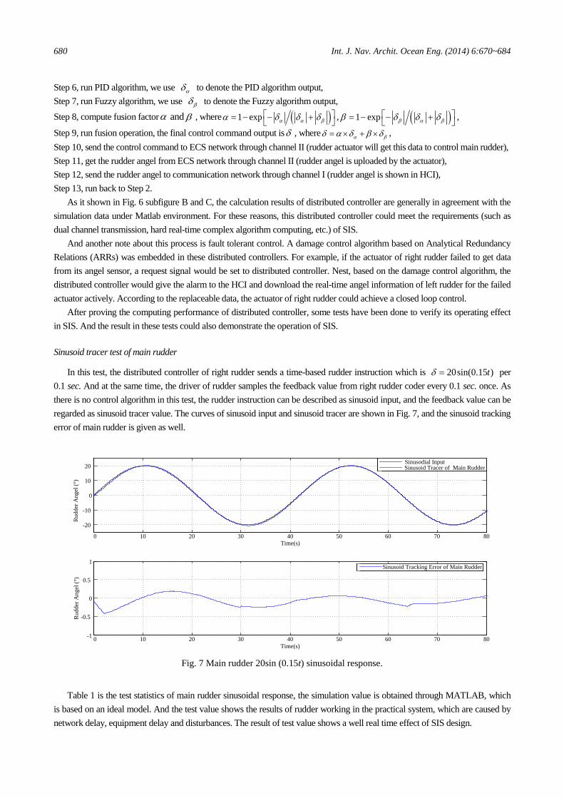
Sinusoid tracer test of main rudder
In this test, the distributed controller of right rudder sends a time-based rudder instruction which is 20sin(0.15 )tδ = per 0.1 sec. And at the same time, the driver of rudder samples the feedback value from right rudder coder every 0.1 sec. once. As there is no control algorithm in this test, the rudder instruction can be described as sinusoid input, and the feedback value can be regarded as sinusoid tracer value. The curves of sinusoid input and sinusoid tracer are shown in Fig. 7, and the sinusoid tracking error of main rudder is given as well.
0 10 20 30 40 50 60 70 80
-20
-10
0
10
20
Sinusodial Input Sinusoid Tracer of Main Rudder
0 10 20 30 40 50 60 70 80-1
-0.5
0
0.5
1
Time(s)
Rud
der A
ngel
(°)
Sinusoid Tracking Error of Main Rudder
Rud
der A
ngel
(°)
Time(s)
Fig. 7 Main rudder 20sin (0.15t) sinusoidal response.
Table 1 is the test statistics of main rudder sinusoidal response, the simulation value is obtained through MATLAB, which
is based on an ideal model. And the test value shows the results of rudder working in the practical system, which are caused by network delay, equipment delay and disturbances. The result of test value shows a well real time effect of SIS design.

Int. J. Nav. Archit. Ocean Eng. (2014) 6:670~684 681
Table 1 Test statistics of main rudder sinusoidal response.
Amplitude error Lagging of phase angel
Test value Simulation value Test value Simulation value
20sin (0.15t) 0.43° 0.026° 0.045 rad 0.002 rad
Synchronism test of fin rudders
In this test, the distributed controllers are in synchronous mode that right rudder and left rudder get a same time-based rudder instruction which is δ = 20sin (0.15t) per 0.1 sec. through the distributed controller of right rudder. And at the same time, each driver of rudder samples the feedback value from its coder every 0.1 sec. once. Similar to the test above, the curves of this test are shown in Fig. 8. And the test values are shown in Table 2. The result shows a good autonomous working ability of flap fin. And the sync error is caused by the discrepancy of flap fins.
0 10 20 30 40 50 60 70 80-20-10
01020
0 10 20 30 40 50 60 70 80-0.5
0
0.5
0 10 20 30 40 50 60 70 80-0.5
0
0.5
0 10 20 30 40 50 60 70 80-0.5
0
0.5
Sync Error
Time(s)
Time(s)
Time(s)
Time(s)
Rud
der
Ang
el (°
)
Rud
der
Ang
el
Erro
r (°)
Rud
der
Ang
el
Erro
r (°)
Rud
der
Ang
el
Erro
r (°)
Sinusodial Input Sinusoid Tracer of Right Flap Rudder Sinusoid Tracer of Left Flap Rudder
Sinusoid Tracer Error of Right Flap Rudder
Sinusoid Tracer Error of Left Flap Rudder
Fig. 8 Test of double flap rudder of 20sin (0.15t) synchronization control.
Table 2 Test statistics of double flap rudder synchronization control.
Error of right flap rudder Error of left flap rudder Sync error
20sin (0.15t) 0.43° 0.4° 0.16°
Roll-main/flap fin and yaw-main/flap rudder cooperative control
In this test, the SIS is required to complete a cooperative control mission which should schedule both rudders and fins to control rolling and yaw of the ship. The cooperative control mission is course-keeping. And the control algorithm we used in this test is based on vector control algorithm. The significant wave height set by the programmable generator is 3.8 meters high and the encounter angle here is 90°. The test statistics values are shown in Table 3. ( )E ⋅ and ( )STD ⋅ represent mean value and root mean square respectively. And α, β, r and f refer to main part, flap part, rudder and fin. For example, rα means main rudder angel here. Predictably, the SIS designed in this paper is able to realize the normal data communication between each part of the system, and completely meet the requirements of a cooperative control mission.
Table 3 Test statistics of roll-main/flap fin and yaw-main/flap rudder vector control (nominal, 3.8 m, 90°).
Statistics Object ( )E ψ ( )STD ψ ( )rE α ( )rSTD α ( )rE β ( )rSTD β
Test value -0.0053 0.0434 -0.0006 0.4860 -0.0003 10.9986 Statistics
Object ( )E ϕ ( )STD ϕ ( )fE α ( )fSTD α ( )fE β ( )fSTD β
Test value 0.0121 0.4379 -0.0391 5.1981 -0.0944 12.3709

682 Int. J. Nav. Archit. Ocean Eng. (2014) 6:670~684
Conclusion and future research
In this paper, the SIS and its different forms are introduced. This paper identified some of the main research topics related to SIS. Some of them have been analyzed since the advent of SIS such as communication type and redundant structure. The ones which came into focus later to improve the ability of data analysis of SIS are information fusion and information decision of SIS. Message display and ship control through SIS are also studied in this paper. And finally, some practical problems on SIS design through SPSIM are analyzed and discussed.
Although SIS has been a very promising research topic for decades, there are challenging problems and unsolved problems to be considered for future research.
By the requirement of the ship informatization, there is no doubt that SIS will become even more complex and large-scale which also raises the difficult of design and implementation a perfect SIS. In order to properly handle the big data flow of sen-sors and actuators through SIS, new scheduling methods and routing algorithms are needed urgently. With the increase of message types uploaded to SIS, global information now is able to be considered into many areas. Among them, old DMS should be replaced or upgraded. For example, a trajectory planning DMS may take into account the tilt of ship’s barycenter in the future. Before that, new requirement analysis should be done. On the other hand, as an emerging and rapidly developing interdisciplinary, the research on SIS can get a wealth of useful references from other areas, such as Cyber-Physical Systems and Hybrid system. But now, the connections of these areas are still not closely tied to. Overall, the research of SIS is mostly rest on the level of the system component, integrative research like TSCE will become the major area of SIS in the future.
ACKNOWLEDGEMENTS
This research is funded by National Natural Science Foundation (NNSF) of China under Grant 51279036.
REFERENCES
Andersen, S.C., Boyle, G.G., Kubischta, M.D., Marshik, J.V. and Robinson, R.P., 1990. Unisys SAFENET data transfer system (Layers 1-4). Conference on Local Computer Networks, Minneapolis, USA, 30 Sepember - 3 October 1990, pp. 343-350.
Andrzej, P. and Maciej, M., 2009. On the adaptation of CAN BUS network for use in the ship electronic systems. Polish Maritime Research, 16(4), pp.62-69.
Aniruddha, G., Krishnakumar, B., Arvind, S., Krishna, J.B., George, E., Gan, D., Emre, T., Jeffrey, P. and Douglas, C.S., 2008.Model driven middleware: A new paradigm for developing distributed real-time and embedded systems. Science of Computer Programming, 73(1), pp.39-58.
Balmat, J.F., Lafont, F., Maifret, R. and Pessel, N., 2011. A decision-making system to maritime risk assessment. Ocean Engineering, 38(1), pp.171-176.
Bakkali, M.C., Mascareñas, F., de la Campa, S., Martín, C., Abad, F.J., Barea, M., Valverde, J.M., Valencia, J. and Chover, J.E., 2007. Feasibility study of advancing and sitting up power line communication (PLC) system under environment of electromagnetic compatibility (EMC) into the ships. 9th International Conference on Digital Object Identifier, Bar-celona, Spain, 9-11 October 2007, pp.1-5.
Calabrese, F., Corallo, A., Margherita, A. and Zizzari, A.A., 2012. A knowledge-based decision support system for ship-board damage control. Expert Systems with Applications, 39(9), pp.8204-8211.
Christian, M., Daniel, S., Susan, R.P., Kevin, J., Jeffrey, O., Stephen, W. and Daniel, G., 2007. Multisensor system for fire detection and situational awareness. SPIE Newsroom, 9 July 2007.
Geer, D.W., 1998. Total ship real time control. Naval Engineers Journal, 110(1), pp.225-234. Goff, J.S. and Million, T.P., 2010. Amphibious assault ship local area network. Proceedings of SPIE - The International
Society for Optical Engineering, Optics and Photonics for Information Processing IV, 7797, pp.779705(1-10). Gold, H. and Suggs, C., 1998. Implementing commercial off-the-shelf (COTS) technologies into a Navy tactical display
communication system. Proceedings-IEEE Military Communications Conference MILCOM, Boston, USA, 18-21 Oc-tober 1998, pp.929-933.

Int. J. Nav. Archit. Ocean Eng. (2014) 6:670~684 683
Gonzalez, M.M., Sobrino, P.C., Alvarez, R.T., Casas, V.D., Lopez, A.M. and Pena, F.L., 2012. Fishing vessel stability assessment system. Ocean Engineering, 41, pp.67-78.
Henry, M., Iacovelli, M. and Thatcher, J., 2009. DDG-1000 engineering control system (ECS). ASNE Intelligent Ship VIII Symposium, Philadelphia, USA, 20-21 May 2009, pp.12-26.
Hu, W.H., Xu, K.Y. and Zhou, W.N., 2007. AIS information display system design based-on the embedded system. ICEMI 2007: Proceedings of 2007 8th international conference on electronic measurement & instruments, Xian, China, 16-18 August 2007, pp.191-195.
Jurdana, I., Tomas, V. and Ivce, R., 2011. Availability model of optical communication network for ship's engines control. International Congress on Ultra Modern Telecommunications and Control Systems and Workshops, 2011, Budapest, Hungary, 5-7 October 2011, pp.1-6.
Källberg, B. and Stråhle, R., 2001. Ship System 2000, a stable architecture under continuous evolution. Proceedings of the Annual Washington Ada Symposium and Summer ACM SIGADA Meeting, Bloomigton, USA, 30 September - 2 Oc-tober 2001, pp.47-51.
Kang, H.J., Lee, D.K., Shin, J.G, and Park, B.J., 2011. Location tracking of moving crew members for effective damage control in an emergency. Defence Science Journal, 61(1), pp.57-61.
Kdouh, H., Brousseau, C., Zaharia, G., Grunfeleder, G. and Zein, G.E., 2012. A realistic experiment of a wireless sensor network on board a vessel. 2012 9th International Conference on Communications, COMM 2012 - Conference Pro-ceedings, Bucharest, Romania, 21-23 June 2011, pp.189-192.
Kdouh, H., Zaharia, G., Brousseau, C., El, Z., Ghais and Grunfelder, G., 2011. ZigBee-based sensor network for shipboard environments. ISSCS 2011 - International Symposium on Signals, Circuits and System Proceedings, Iasi, Romania, 30 June - 1 July 2011, pp.229-232.
Li, Z., Yan, X., Guo, Z., Liu, P., Yuan, C. and Peng, Z., 2012. A new intelligent fusion method of multi-dimensional sensors and its application to tribo-system fault diagnosis of marine diesel engines. Tribology Letters, 47(1), pp.1-15.
Lin, C.C., Lin, H., Li, L.N., Zhou, J.W. and Ou, Y.P., 2009. Development of the Integrated Target Information System of the Marine Radar and AIS Based on ECDIS. 2009 5th International Conference on Wireless Communications, Net-working and Mobile Computing, Beijing, China, 24-26 September 2009, pp.4820-4823.
Liu, S., Chang, X.C. and Li, G.Y., 2010. Synchronous-ballistic control for a twin-rudder ship. Control Theory and Appli-cations, 27(12), pp.1631-1636.
Liu, S., Fang, L. and Yu, P., 2007. More effective damping of roll through joint use of rudders and fins. Harbin Gongcheng Daxue Xuebao/Journal of Harbin Engineering University, 28(10), pp.1109-1115.
Liu, S., Fang, L., Li, G.Y. and Li, B., 2008. Fin/Flap fin joint control for ship anti-roll system. Proceedings of 2008 IEEE International Conference on Mechatronics and Automation, ICMA 2008, Takamatsu, Japan, 5-8 August 2008, pp.386-391.
Liu, S., Wang, M. and Zhang, L., 2012. Research on information fusion of infrared and radar sensor based on SVM. Pro-ceedings of 2012 International Conference on Measurement, Information and Control, MIC 2012, Harbin, China, 18-20 May 2012, pp.98-101.
Lister, J.R. and Rosie, J.D., 1995. A digital maritime integrated internal communication system. Journal of Naval Engi-neering, 35(3), pp.504-519.
Lu, H., 2012. Design on IPNCS of electrical propulsion ship based on real-time Ethernet. International Conference on Future Energy, Environment, and Materials (FEEM), 16, pp.1707-1713.
Martin, W. and Richard, F., 1984. Current ttrends in naval data handing systems. Naval Engineers Journal, 96(3), pp.128-141.
Martins, P.T. and Lobo, V.S., 2011. Real-Time decision support system for managing ship stability under damage. IEEE OCEANS Conference, Santander, Spain, 6-9 June 2011, pp.1-7.
Meier, S.J. and Manfredi, A., 2006. Gigabit ethernet data multiplex system (GEDMS) - Enabling the netcentric evolution of navy combatants. IEEE Military Communications Conference (MILCOM 2006), Orlando, USA, 29-31 October 2007, pp.27-33.
Minor, C.P., Johnson, K.J., Rose-Pehrsson, S.L., Owrutsky, J.C., Wales, S.C., Steinhurst, D.A. and Gottuk, D.T., 2007. Data fusion with a multisensor system for damage control and situational awareness. 2007 IEEE Conference on Ad-

684 Int. J. Nav. Archit. Ocean Eng. (2014) 6:670~684
vanced Video and Signal Based Surveillance, AVSS 2007 Proceedings, London, UK, 5-7 September 2007, pp.313-317. Murphy, S.P., 2004. An integrated approach to U.S. Navy shipboard navigation. IEEE Techno-Ocean '04: Bridges across
the Oceans - Conference Proceedings, Kobe, Japan, 9-12 November 2004, pp.802-806. Paik, B.G., Cho, S.R., Park, B.J., Lee, D.K. and Bae, B.D., 2010. Development of real-time monitoring system using wired
and wireless networks in a full-scale ship. International Journal of Naval Architecture and Ocean Engineering, 2(3), pp.132-138.
Paik, B.G., Cho, S.R., Park, B.J., Lee, D.K., Bae, B.D. and Yun, J.H., 2009. Characteristics of wireless sensor network for fullscale ship application. Journal of Marine Science and Technology, 14(1), pp.115-126.
Park, Z.W. and Kim, M.K., 2005. Design of an integrated fieldbus gateway. 9th Russian-Korean International Symposium on Science and Technology, KORUS-2005, Novosibirsk, Russia, 26 June - 2 July 2005, pp.843-846.
Paulos, A.M., Sinclair, A. and Loyall, J.P. 2011. Evaluating QoS-enabled information management services in a Navy operational context. Defense Transformation and Net-Centric Systems 2011, Orlando, USA, 27-28 April 2011, pp. 806203(1-23).
Qi, L. and Yu, M.H., 2011. Research on ship CPP networked control system based on SVM, GPC and QS. Advances in In-telligent and Soft Computing, 111, pp.177-184.
Roa, M., 2007. ABS naval vessel rules (NVR) for mission critical networks, software development, and safety critical con-trol systems. IEEE Electric Ship Technologies Symposium, Arlington, USA, 21-23 May 2007, pp.38-144.
Simoncic, R., Weaver, A.C., Cain, B.G. and Colvin, M.A., 1988. Shipnet: A real-time local area network for ships. Con-ference on Local Computer Networks, Minneapolis, USA, 10-12 October 1988, pp.424-432.
Staroswiecki, M., Hoblos, G. and Aitouche, A., 2004. Sensor network design for fault tolerant estimation. International Journal of Adaptive Control and Signal Processing, 18(1), pp.55-72.
Statheros, T., Howells, G. and McDonald-Maier, K., 2008. Autonomous ship collision avoidance navigation concepts, technologies and techniques. Journal of Navigation, 61, pp.129-142.
Talukdar, K., Stojanovic, M. and Freitag, L., 2006. Through-the-hull acoustic communication technology. Sea Technology, 47(5), pp.45-49.
Thomsett, D.G., 1993. The evolution of successful C3I systems. Journal of Naval Engineering, 34(2), pp.299-307. Vincent, P.S., Gardiner, C.P., Wilson, A.R., Ellery, D. and Armstrong, T., 2008. Installation of a sensor network on an
RAN Armidale Class Patrol Boat. Materials Forum, 33, pp.307-316. Wibowo, S. and Deng, H.P., 2012. Intelligent decision for effectively evaluating and selecting ships under uncertainly in
marine transportation. Expert Systems with Applications, 39(8), pp.8911-6920. Xu, P., 2012. Ship cabin environment monitoring system based on wireless sensor network. World Automation Congress
Proceedings, 2012 World Automation Congress, WAC, Puerto Vallarta, Mexico, 24-28 June 2012, pp.1-4. Young, S.S. and Gubbins, V.R. 1997. Smart ship and reduced manning in the United States Navy. Journal of Naval Engi-
neering, 37(2), pp.226-239. Zhang, X.G., Peng, G.J., Chi, T.H. and Ji, C.L., 2006. Research on sea digital map used for ship navigation. IEEE Confe-
rence on Geoscience and Remoto Sensing Symposium, Denver, USA, 31 July – 4 August 2006, pp.872-875. Zhao, Z.H., Zhou, W. and Wang, N., 2009. Shipping monitoring system based on GPS and GPRS technology. 2009 WASE
International Conference on Information Engineering (ICIE 2009), Taiyuan, China, 10-11 July 2009, pp.346-340. Zhou, Y.Q. and Guo, C., 2010. The coordinate control of ship steering and main propulsion in constrict waters for collision
avoidance. Proceedings of 2010 International Conference on Logistics Systems and Intelligent Management, Harbin, China, 9-10 January 2010, pp.568-572.