shipping, rigging, hoisting and assembly manual …€¦ · shipping, rigging, liting and assemly...
TRANSCRIPT

SHIPPING, RIGGING, HOISTING AND ASSEMBLY MANUALENERGY RECOVERY VENTILATORS
RENEWAIRE.COM
LE6XLE8XLE10X

SHIPPING, RIGGING, LIFTING AND ASSEMBLY: LE MODELS
RENEWAIRE.COM INSTALLATION, OPERATION AND MAINTENANCE MANUAL 1.800.627.44992
IMPORTANT SAFETY INFORMATION WARNING
RISK OF DEATH 0R SERIOUS INJURY
Hoisting heavy equipment overhead is inherently dangerous. Failure to properly rig the ERV for hoisting or the use of incorrect rigging equipment may result in the ERV falling during hoisting.Improper work procedures may result in death or serious injury to workers. Rigging, hoisting and assembly are to be performed by skilled and experienced personnel. OSHA-approved work guidelines are to be strictly followed. Before proceeding with installation, read all instructions, verifying that all the parts are included.The information in this manual is provided as a guideline and does not neccessarily meet all local codes. It is the installer’s responsibility to comply with all local codes and OSHA-approved safety practices.
RISK OF DAMAGE TO ENTHALPIC CORES
Whenever working within the ERV cabinet, protect the enthalpic cores from accidental damage. The core media is subject to damage from dropped tools or other foreign objects.
RISK OF DAMAGE TO ERV CABINET
Incorrect lifting can cause damage to the unit. Do not lift joined unit by the 4 corner lifting lugs only. Secure lifting cables to the center lifting lugs also.All lifting lugs provided must be used. Never lift the unit or modules from the top of the unit.
This unit is intended for general ventilating only. Do not use to exhaust hazardous or explosive materials and vapors. Do not connect this equipment to range hoods, fume hoods or collection systems for toxics.
This unit is for ventilating finished structures only. It is not to be used until after all construction has been completed and construction debris and dust are cleaned from the Occupied Space.
Do not lift joined unit by the 4 corner lifting lugs only. Secure lifting cables to the center lifting lugs also.All lifting lugs provided must be used. Never lift the unit or modules from the top of the unit.Incorrect lifting can cause damage to the unit.
This equipment is to be installed by following Industry Best Practices and all applicable codes. Any damage to components, assemblies, subassemblies or the cabinet which is caused by improper installation practices will void the warranty.
NOTICE
NOTICE
NOTICE
NOTICE
NOTICE
NOTICE
IMPORTANT IMPORTANTIf this unit is installed in an area where it may draw air from a nearby fuel-burning device such as a gas furnace or water heater, verify that the air being extracted by the ERV does not conflict with proper operation of the fuel-burning device.
This unit can be delivered in two modules for on-site assembly or as a completely assembled unit (additional charges apply).See separate unit-specific Installation, Operation and Maintenance manual for further information.

SHIPPING, RIGGING, LIFTING AND ASSEMBLY: LE MODELS
3 1.800.627.4499 INSTALLATION, OPERATION AND MAINTENANCE MANUAL RENEWAIRE.COM
OWNER INFORMATION
IMPORTANT USER INFORMATION
SAVE THIS MANUAL
In the unlikely event that factory assistance is ever required, information located on the unit label will be needed.
UNIT INFORMATION
Configuration (Option) Code
Unit Label (typical)

SHIPPING, RIGGING, LIFTING AND ASSEMBLY: LE MODELS
RENEWAIRE.COM INSTALLATION, OPERATION AND MAINTENANCE MANUAL 1.800.627.44994
OWNER INFORMATION
TABLE OF CONTENTS
UNIT INFORMATION 31.0 SHIPPING 6
1.1 RECEIVING AND HANDLING 61.2 STORAGE BEFORE INSTALLATION 6
2.0 RIGGING 72.1 REQUIRED RIGGING EQUIPMENT 7
3.0 FORKLIFT REQUIREMENTS 9
4.0 MODULE ASSEMBLY 94.1 CONFIGURATION LABEL 94.2 ASSEMBLY PREPARATION 94.3 REMOVE SHIPPING STRAPS 104.4 APPLY FOAM GASKET TAPE 104.5 JOIN MODULES TOGETHER 11
4.5.1 Bolt Together at Lifting Lugs 114.5.2 Bolt Together Mating Roof Beams 124.5.3 Caulk The Seams 134.5.4 Install Joining Roof Cap 134.5.5 Install Assembly Straps 144.5.6 Install Roof End Joining Caps 14
4.6 CONNECT THE WIRING HARNESS 154.7 INSTALL WEATHERHOODS 164.8 INSTALL MERV-8 FILTERS 17
5.0 ROOFTOP CURB DIMENSIONS 185.1 LE6XRT CURBS 185.2 LE8XRT CURBS 185.3 LE10XRT CURBS 19
6.0 ROOFTOP UNIT DIMENSIONS 206.1 LE6XRTH-F DIMENSION DRAWING 206.2 LE6XRTV-R DIMENSION DRAWING 206.3 LE8XRTH-F DIMENSION DRAWING 216.4 LE8XRTV-R DIMENSION DRAWING 216.5 LE10XRTH-F DIMENSION DRAWING 226.6 LE10XRTV-R DIMENSION DRAWING 22
7.0 INDOOR UNIT DIMENSIONS 237.1 LE6XINH DIMENSION DRAWING 237.2 LE6XINV DIMENSION DRAWING 237.3 LE8XINH DIMENSION DRAWING 247.4 LE8XINV DIMENSION DRAWING 247.5 LE10XINH DIMENSION DRAWING 257.6 LE10XINV DIMENSION DRAWING 25
8.0 LE6X CORNER WEIGHTS 268.1 LE6XRT CORNER WEIGHTS 268.2 LE6XINH CORNER WEIGHTS 278.3 LE6XINVH CORNER WEIGHTS 27
9.0 LE8X CORNER WEIGHTS 289.1 LE8XRT CORNER WEIGHTS 289.2 LE8XINH CORNER WEIGHTS 299.3 LE8XINVH CORNER WEIGHTS 29
10.0 LE10X CORNER WEIGHTS 3010.1 LE10XRT CORNER WEIGHTS 3010.2 LE10XINH CORNER WEIGHTS 3110.3 LE10XINVH CORNER WEIGHTS 31

SHIPPING, RIGGING, LIFTING AND ASSEMBLY: LE MODELS
5 1.800.627.4499 INSTALLATION, OPERATION AND MAINTENANCE MANUAL RENEWAIRE.COM
TABLE OF ILLUSTRATIONS
Unit Label (typical) 3LE ERV Hood Shipping Location (typ) 6Rigging Assembly Graphic 1 8Rigging Assembly Graphic 2 8Corner Lifting Lug (typ) 8Shipping Straps Location 10Foam Gasketing Tape Location (typ) 10Module Positioning Technique 11LE Indoor Unit Base Bolt Locations 11LE Rooftop Unit Base Bolt Locations 11Alignment / Spacer Bolt Location 11Roof Beam Assembly Graphic 2 12Roof Beam Assembly Graphic 1 12Roof Beam Assembly Bolt Locations 12Roof Cap Caulking 13Roof Beam Caulking 13Assembly Strap Locations 14Roof End Joining Caps 14Assembly Strap Installation 14Wiring Harness Access Panel 15Wiring Harness Routing 15Access Panel Removal 15Wiring Harness Connections 15OA Hood Screw Locations 16EA Hood Screw Locations 16Access Panel Installation 16OA Hood Installation 16EA Hood Installation 16Filter Spacers 17Filter Racks 17Filter Extractor Hook 17

SHIPPING, RIGGING, LIFTING AND ASSEMBLY: LE MODELS
RENEWAIRE.COM INSTALLATION, OPERATION AND MAINTENANCE MANUAL 1.800.627.44996
SHIPPING
1.0 SHIPPING
1.1 RECEIVING AND HANDLING
1.2 STORAGE BEFORE INSTALLATION
All ERVs are palletized and then shipped by common carrier. It is the installer’s / customer’s responsibility to coordinate delivery and properly handle the shipment during unloading and storage.
Upon delivery of the ERV, inspect it carefully for shipping damage and completeness. Verify the pres-ence of any accessories such as external hoods that are to be field-installed or filters that are shipped loose. If shipping damage is discovered, take digital pictures and note the visible damage on the ship-ping manifest. Notify your RenewAire dealer immediately.
Note that whenever possible, accessories such as weather hoods are assembled and then secured for shipping inside the ERV. See photo below.
LE ERV Hood Shipping Location (typ)
Hoods are assembled at the factory and then secured for shipment inside the ERV.
LE models can be delivered in two modules for on-site assembly or as a complete unit (additional charges apply).
In all cases, extra protective pallet materials may have been added; this material was added at the factory to protect the unit or modules during shipping.
In all cases, when shipped as modules, assembly materials ship loose and can be found inside the modules. Note that assembly materials must be removed and installed prior to unit operation.
For rooftop models, the outdoor air weather hoods ship loose and can be found inside the modules. Note that weather hoods and assembly materials must be removed and installed prior to unit operation.
If installation will not occur immediately following delivery, store equipment in a dry protected area away from construction traffic and in the proper orientation as marked on the packaging with all in-ternal packaging in place.
When placing the ERV on the ground, the placement area should be flat and level. Take care to avoid twisting or wracking of the unit.

SHIPPING, RIGGING, LIFTING AND ASSEMBLY: LE MODELS
7 1.800.627.4499 INSTALLATION, OPERATION AND MAINTENANCE MANUAL RENEWAIRE.COM
RIGGING
2.0 RIGGING
2.1 REQUIRED RIGGING EQUIPMENT
The unit comes equipped with base rail lifting lugs at the lower 4 corners and in the middle of the unit.
Each lifting lugs come equipped with a 2” diameter hole which will accommodate a 1.5” dia. schedule 40 steel pipe (not provided).
Unit or module sections shall be lifted by cables attached to all of the lifting lugs.
If cables or chains are used to lift the unit they must be the same length. Care should be taken not to damage the cabinet, dampers, or electrical box.
Adjustable spreader bars should be used to properly support the unit in order to properly distribute the load thus applying an even vertical lifting force to all of the lifting lugs. This will prevent structural damage to the unit.
Also adjustable spreader bars should be used to maintain the required 10” clearance between the cables and the cabinet or any of the equipment attached to the unit or modules.
Provide additional blocking or covering as required.
Secure hooks and cables at all lifting points.
Take up slack in cables gradually as to avoid sudden movements as this may cause the unit or modules to shift.
Suspending the unit or modules for an extended period of time is not recommended and it is advised to place the unit as soon as possible after lifting.
Do not lift in high winds.
RenewAire will not be responsible for any damage during the rigging, lifting or installing of the unit or modules.
Refer to Corner Weight Charts for exact center of gravity.
All rigging equipment is to be provided by the installing Contractor.
Rigging procedures may differ depending on the physical dimensions of the unit or modules, it’s loca-tion, the job site, or Installing Contractor preferences.
Tools needed (Suggested):Crane to lift proper capacityAdjustable spreader barsCables1.5” Dia. steel pipe schedule 40.Tools to pull modules together, chains, bar clamps, come alongs etc.Miscellaneous (SAE) wrenches and 1/2” drive socket wrenches with short extensions

SHIPPING, RIGGING, LIFTING AND ASSEMBLY: LE MODELS
RENEWAIRE.COM INSTALLATION, OPERATION AND MAINTENANCE MANUAL 1.800.627.44998
RIGGING
www.renewaire.com (800) 627- 4499 [email protected]
www.renewaire.com (800) 627- 4499 [email protected]
www.renewaire.com (800) 627- 4499 [email protected] Lifting Lug (typ)
Rigging Assembly Graphic 1
Rigging Assembly Graphic 2

SHIPPING, RIGGING, LIFTING AND ASSEMBLY: LE MODELS
9 1.800.627.4499 INSTALLATION, OPERATION AND MAINTENANCE MANUAL RENEWAIRE.COM
ASSEMBLY
3.0 FORKLIFT REQUIREMENTS
4.0 MODULE ASSEMBLY
When lifting individual modules, forklift extensions must be used and a minimum length of 72” (96” preferred).
When lifting modules off the pallets:
If entering from the door side or the open side of the module ensure forks extend in far enough as to catch the furthest away stringer with fork extensions.
If entering from the side of the module, insure forks extend all the way through the module.
NOTICEDo not attempt to lift a rooftop module off the pallet from the door side or open side as there are no stringers under the unit to carry the load.Assembled modules should never be lifted using a forklift.
4.1 CONFIGURATION LABEL
4.2 ASSEMBLY PREPARATION
RenewAire LE series Energy Recovery Ventilators can either be built and shipped factory assembled or be ordered unassembled for applications where modules must be manipulated separately. If the unit was ordered unassembled, then you will need to assemble the modules in the field.
Each module is labeled with a configuration and serial number label. Locate these labels and insure each module assembled together have the same configuration and serial number. See the image on page 3 of this manual.
If for any reason you are unable to identify a module or its position in the final assembly, then consult the Installation Contractor or RenewAire Customer Service.
Extra protective pallet material has to be removed prior to assembly. This additional pallet material was added at the factory to protect the unit during shipping.
Also, plywood protective packaging material has to be removed from modules before assembly.
It is desirable to situate all required modules in the installation location as near as possible to the order in which they will be connected. Be sure to leave enough space to work between modules before connection. Gasket tape will be applied before assembling the modules.
All materials for assembling the modules are supplied by RenewAire.

SHIPPING, RIGGING, LIFTING AND ASSEMBLY: LE MODELS
RENEWAIRE.COM INSTALLATION, OPERATION AND MAINTENANCE MANUAL 1.800.627.449910
ASSEMBLY
4.3 REMOVE SHIPPING STRAPS
4.4 APPLY FOAM GASKET TAPE
Remove shipping straps from opening/mating ends before joining modules and operating the unit. Shipping straps are attached to the modules at the factory. These straps insure proper rigidity when shipping and lifting. Once the straps are removed they may be disposed of along with the screws that held them in place.
www.renewaire.com (800) 627- 4499 [email protected]
Apply 1/2” X 1” gasket tape (provided), as shown below. Gasket tape creates an airtight seal between modules. The adhesive backing on the gasket tape is easily repositioned during assembly if needed. However, if gasket tape is allowed to set more than 48 hours, it will be difficult to reposition.
INSTALL FOAM GASKETING TAPE AS SHOWN HERE.
(Gasketing is shown in red for clarity)
NOTE: Failure to apply foam gasketing tape as shown here will compromise water and
airtight seal of the unit.
Foam Gasketing Tape Location (typ)
Shipping Straps Location

SHIPPING, RIGGING, LIFTING AND ASSEMBLY: LE MODELS
11 1.800.627.4499 INSTALLATION, OPERATION AND MAINTENANCE MANUAL RENEWAIRE.COM
ASSEMBLY
4.5 JOIN MODULES TOGETHER
4.5.1 Bolt Together at Lifting Lugs
Align modules and push together using forklift or other means, compressing the gasket tape. The lower lifting lugs are equipped with 2” diameter holes that 1.5” dia. (2” OD) steel pipe could be used to assist in alignment. See Lifting Lug illustration on page 8 of this manual. Joining lift lugs also have a spacing bolt at the tip of one lug that will fit into the empty lug hole of the other module for alignment and lug tip spacing.
After positioning the modules together, compressing the gasket tape, insert eight 3/8” - 16 x 1-1/4 plated hex head bolts through the holes on the lifting lugs and base rail (LE-IN) or base supports (LE-RT) of the two adjacent modules. Use 3/8” washers between the bolt head and the unit and between the nut and the unit. Fasten the nuts to the bolts secure the bases of the two modules together tightly.
ALIGNMENT / SPACER
BOLT
LE INDOOR UNITS:INSTALL 2 BOLTS IN THE MATING LIFT-ING LUGS AND THEN 2 MORE BOLTS IN THE MATING BASE RAILS. TYPICAL
EACH SIDE OF LE UNIT.
2 BOLTS THROUGH LIFTING LUGS (EACH SIDE OF UNIT)
HAND HOLES (TYP, EACH SIDE OF UNIT)
2 BOLTS THROUGH LIFTING LUGS (EACH SIDE OF UNIT)
2 BOLTS THROUGH BASE RAILS (EACH SIDE OF UNIT). ACCESS BOLT AND NUT THROUGH
THE HAND HOLES IN EACH MODULE SIDE BASE RAIL TO BE JOINED.
2 BOLTS THROUGH BASE SUP-PORTS (EACH SIDE OF UNIT).
ACCESS BOLT AND NUT THROUGH HAND HOLES IN
EACH MODULE SIDE BASE RAIL TO BE JOINED.
LE ROOFTOP UNITS:INSTALL 2 BOLTS IN THE
MATING LIFTING LUGS AND THEN 2 MORE BOLTS IN BASE
SUPPORT.
LE Indoor Unit Base Bolt Locations
LE Rooftop Unit Base Bolt Locations
Alignment / Spacer Bolt LocationModule Positioning Technique

SHIPPING, RIGGING, LIFTING AND ASSEMBLY: LE MODELS
RENEWAIRE.COM INSTALLATION, OPERATION AND MAINTENANCE MANUAL 1.800.627.449912
ASSEMBLY
4.5.2 Bolt Together Mating Roof Beams
Use bar clamps, or other non-destructive winching device to pull the top of the modules together tightly compressing the gasket. After aligning the 4 roof bolt locations, insert 1/4” - 20 x 1.00” Grade 5 zinc plated hex head bolts through the holes in the roof beam. Secure the nuts to secure the roof section.
www.renewaire.com (800) 627- 4499 [email protected]
AFTER THE LIFTING LUG AS-SEMBLIES HAVE BEEN BOLTED TOGETHER, RAISE ONE END OF THE UNIT TO COMPRESS THE GASKETING AND BRING BOTH OF THE MATING ROOF BEAMS
INTO TIGHT CONTACT.
USE A PIPE CLAMP TO ADJUST THE ROOF BEAMS LATERALLY AND THEN BOLT TOGETHER
THE TWO ROOF BEAMS.
Roof Beam Assembly Graphic 1
Roof Beam Assembly Graphic 2
Roof Beam Assembly Bolt Locations

SHIPPING, RIGGING, LIFTING AND ASSEMBLY: LE MODELS
13 1.800.627.4499 INSTALLATION, OPERATION AND MAINTENANCE MANUAL RENEWAIRE.COM
ASSEMBLY
4.5.3 Caulk The Seams
4.5.4 Install Joining Roof Cap
Attention should be taken to assure the modules are forming an air and water tight seal.
Apply a continuous ½” bead of Tremsil 600 Silicone Sealant caulk (provided) at the seam along the entire roof and sides of the unit.
www.renewaire.com (800) 627- 4499 [email protected]
A galvanized cap roof flange is provided to seal the roof seam and to maintain a water and airtight seal. The cap roof flange is provided with pre-drilled holes. #12 X .75 hex head tek screw w/washers are provided to attach the cap roof flange.
For best results, use a lower torque setting on the power drill. Be careful not to over tighten the screw.
www.renewaire.com (800) 627- 4499 [email protected]
NOTE: Failure to apply caulk in these locations will compromise the water and airtight seal
of the unit.
NOTE: Failure to install the roof cap will compromise the water and airtight integrity of
the unit.
Roof Beam Caulking
Roof Cap Caulking

SHIPPING, RIGGING, LIFTING AND ASSEMBLY: LE MODELS
RENEWAIRE.COM INSTALLATION, OPERATION AND MAINTENANCE MANUAL 1.800.627.449914
ASSEMBLY
4.5.5 Install Assembly Straps
4.5.6 Install Roof End Joining Caps
Two (2) galvanized metal assembly straps are used to secure the module seams to assist in maintain-ing a water and airtight seal and provide structural rigidity during lifting. One (1) used on each side of the unit. These straps are provided with pre-drilled holes. #12 X 3/4” hex head tek screw w/washers are provided to attach the joining straps to the unit. For additional protection, caulk sides of straps after attachment.
For best results, use a lower torque setting on the power drill. Be careful not to over tighten the screw.
www.renewaire.com (800) 627- 4499 [email protected]
Two (2) galvanized roof cap ends are provided to seal the top end of each module and maintain a water and airtight seal. The roof cap joining ends are provided with pre-drilled holes. #12 X 3/4” hex head tek screw w/washers are provided to attach these roof cap joining ends to the unit.
www.renewaire.com (800) 627- 4499 [email protected]
NOTE: Failure to install the assembly straps will compromise the structural integrity of the unit and cause damage during lifting. It will also compromise the water and airtight integrity of the unit.
NOTE: Failure to install roof cap ends will compromise the structural integrity of the unit and cause unit damage during lifting. It will also compromise the water and airtight integrity of the unit.
Assembly Strap Locations Assembly Strap Installation
Roof End Joining Caps

SHIPPING, RIGGING, LIFTING AND ASSEMBLY: LE MODELS
15 1.800.627.4499 INSTALLATION, OPERATION AND MAINTENANCE MANUAL RENEWAIRE.COM
ASSEMBLY
4.6 CONNECT THE WIRING HARNESS
Wiring Harness Access Panel
Wiring Harness Routing
Access Panel Removal
Wiring Harness Connections
Internal wiring connections are required after modules are fastened together, and before connection of unit supply power. For INH and RT models, the back module comes pre-wired with the exhaust air blower wires being routed from the motor to the open end of the module. The wiring harnesses end in plugs, ready for connection.
If the back module is equipped with isolation dampers, they are also pre-wired with the damper wires being routed from the damper actuators to the open end of the module. The ends of the damper wiring harnesses also end in plugs, ready for connection.
After the modules are joined together, open the electrical connection cover on the E-Box side of the front module by removing screws in the access panel. The access panel is located in the upper left corner of the front module, to the left of the E-Box.
www.renewaire.com (800) 627- 4499 [email protected]
www.renewaire.com (800) 627- 4499 [email protected]
Inside the access panel are low voltage and high voltage wiring connection compartments. The low voltage compartment is the lower compartment and the high voltage compartment is the upper compartment. Both compartments are open on the left side to access the wiring harness plugs that are coming from the exhaust air blower and isolation dampers (if equipped).
www.renewaire.com (800) 627- 4499 [email protected] (800) 627- 4499 [email protected]
Reach through the open left side of the compartments and into the rear module. Guide the wiring harness(es) into the wiring connection compartments in the front module. Plug each wiring harness into its matching connector, located in the wiring connection compartments. Secure excess wire with wire ties.

SHIPPING, RIGGING, LIFTING AND ASSEMBLY: LE MODELS
RENEWAIRE.COM INSTALLATION, OPERATION AND MAINTENANCE MANUAL 1.800.627.449916
ASSEMBLY
4.7 INSTALL WEATHERHOODS
Rooftop units (RT models) have weatherhoods that are shipped loose and must be field-installed. Installation of the hoods is normally performed after all rigging and hoisting is completed because of the chance of damage to the hoods by the rigging equipment.
All weatherhoods have a flange on the top rear that must be inserted behind the roof panel overhang. To install any hood, remove the factory-installed roof edge screws and keep them for re-use.
www.renewaire.com (800) 627- 4499 [email protected]
www.renewaire.com (800) 627- 4499 [email protected]
www.renewaire.com (800) 627- 4499 [email protected]
www.renewaire.com (800) 627- 4499 [email protected]
Slide the top flange of the OA air hood beneath the roof panel overhang. Reinstall the screws in the roof edge and then install screws along the sides and lower edge of each hood.
Slide the top flange of the EA air hood beneath the roof panel overhang. Reinstall the screws in the roof edge and then install screws along the sides and lower edge of each hood.
OUTSIDE AIR HOODS
EXHAUST AIR HOODS
Replace the access cover by sliding the top edge of the cover behind the edge of the roof pan and replace the screws. Caulk the sides and bottom of the access panel with factory-supplied caulk.
www.renewaire.com (800) 627- 4499 [email protected]
Access Panel Installation
OA Hood Screw Locations
EA Hood Screw Locations
OA Hood Installation
EA Hood Installation
SHIPPING, RIGGING, LIFTING AND ASSEMBLY: LE MODELS
17 1.800.627.4499 INSTALLATION, OPERATION AND MAINTENANCE MANUAL RENEWAIRE.COM
ASSEMBLY
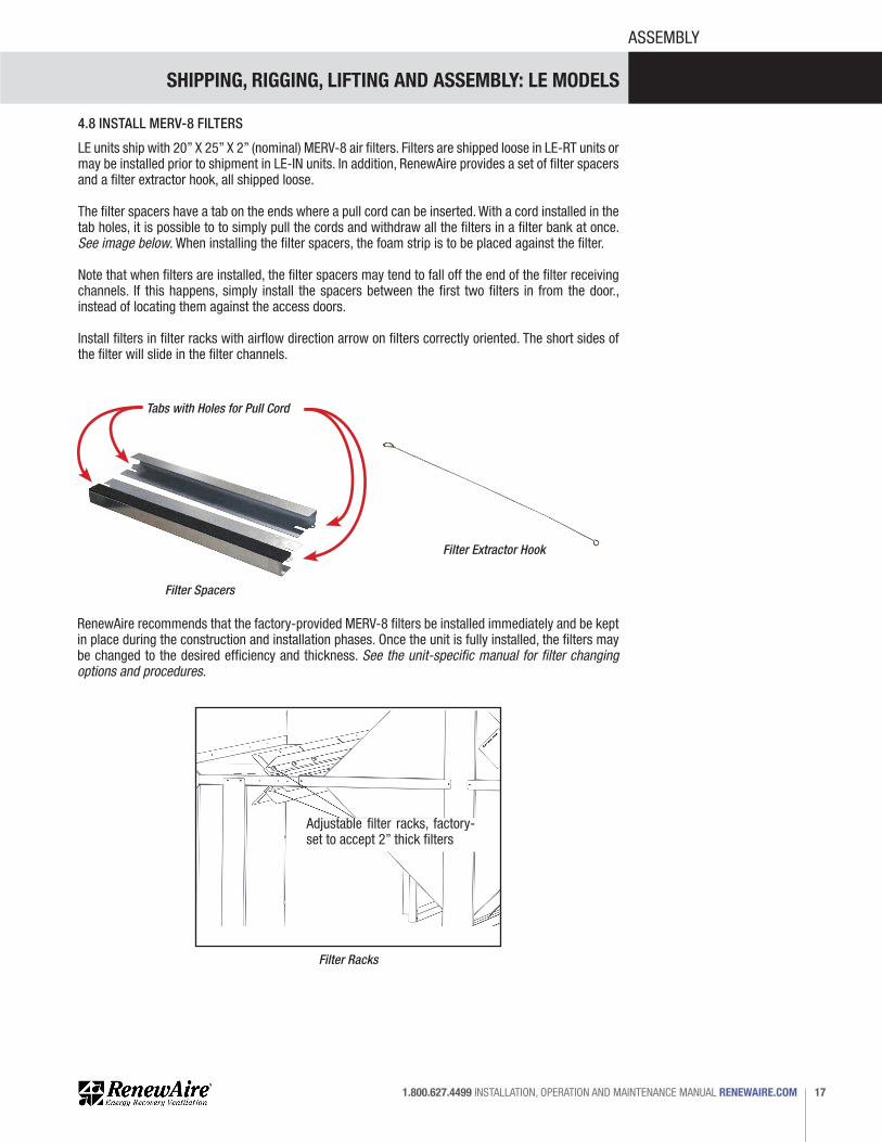
4.8 INSTALL MERV-8 FILTERS
LE units ship with 20” X 25” X 2” (nominal) MERV-8 air filters. Filters are shipped loose in LE-RT units or may be installed prior to shipment in LE-IN units. In addition, RenewAire provides a set of filter spacers and a filter extractor hook, all shipped loose.
The filter spacers have a tab on the ends where a pull cord can be inserted. With a cord installed in the tab holes, it is possible to to simply pull the cords and withdraw all the filters in a filter bank at once. See image below. When installing the filter spacers, the foam strip is to be placed against the filter.
Note that when filters are installed, the filter spacers may tend to fall off the end of the filter receiving channels. If this happens, simply install the spacers between the first two filters in from the door., instead of locating them against the access doors.
Install filters in filter racks with airflow direction arrow on filters correctly oriented. The short sides of the filter will slide in the filter channels.
Filter Extractor Hook
Filter Spacers
Filter Racks
Tabs with Holes for Pull Cord
RenewAire recommends that the factory-provided MERV-8 filters be installed immediately and be kept in place during the construction and installation phases. Once the unit is fully installed, the filters may be changed to the desired efficiency and thickness. See the unit-specific manual for filter changing options and procedures.
www.renewaire.com (800) 627- 4499 [email protected]
Adjustable filter racks, factory-set to accept 2” thick filters

SHIPPING, RIGGING, LIFTING AND ASSEMBLY: LE MODELS
RENEWAIRE.COM INSTALLATION, OPERATION AND MAINTENANCE MANUAL 1.800.627.449918
CURB DIMENSIONS
5.0 ROOFTOP CURB DIMENSIONS5.1 LE6XRT CURBS
5.2 LE8XRT CURBS
FOR THE MOST COM
PLETE AND CURRENT INFORMATION VISIT R
EN
EW
AIR
E.C
OM
LE-SERIES
105
2" DuctFlange Typ. 73 3/8"
Lifting Lugs
19 5/8"Typ.
22 1/4" 69 1/4" Case
111 1/8" Overall
2" Typ.
FRONT VIEW
Pressure Ports(4) Typ.
FA RTRONLY
FARTV
ONLY RA
122 5/8" Case 125 3/8" Overall
OA Inlets,OA Damper
Locations(Optional)
RIGHT VIEW
53
1/2"
44 5/8"
8 7
/8"
25 1/4"
4"
65
5/8"
Cas
e
71
1/8"
Ove
rall
CL 11 3/8"(5) 7/8"Knockouts
CL 5 1/4"(2) 7/8"Knockouts
DisconnectSwitch
E-BoxEA Outlet
13 3/8" X 15 1/2"ElectricalConnectionCover
FA (RTR)32" X 24" Duct ReceivingFlange
18 3/8" 49 5/8"
41"
46"
36" E-BoxMinimum
Service Area
111" MinimumService Area
60 1
/4"
Min
imum
Bl
ower
Ser
vice
A
rea
Typ.
69 3/4" MinimumService Area
TOP VIEW
DoorSwing
DoorSwing
DoorSwing
DoorSwing
OA
OA
EA
FA (RTV)16 1/8" X 19 1/2"
Opening
RA 24" X 32"Opening
RA Damper Location(Optional)
115
1/4
" O.D
.
64 1/4" O.D.
3" 60 1/2" I.D.
17
1/4"
3
3"
20" 25" 9 1/2"
AA
TOP VIEW
CURB LE6X
FA RA
1 7/8"
3"
14"
SECTION A-A
CURB CROSS-SECTION A-A (TYP.)
1 1/2" X 1/4"Neoprene Gasket
3/4" X 3 1/2"Wooden Nailer
LEFT VIEW
Model: LE6X RTV/RTRDrawing Type: Unit DimensionVersion: MAY18
ABBREVIATIONSEA: Exhaust Air to outsideOA: Outside Air intakeRA: Room Air to be exhaustedFA: Fresh Air to insideRTV: Rooftop Vertical RA & FARTR: Rooftop Vertical RA Only
INSTALLATION ORIENTATIONUnit must be installed in orientationshown.
NOTE:1. UNLESS OTHERWISE SPECIFIED,DIMENSIONS ARE ROUNDED TO THE NEAREST EIGHTH OF AN INCH.
2. SPECIFICATIONS MAY BE SUBJECT TO CHANGE WITHOUT NOTICE.
LE6XRT (RTV/RTR) Energy Recovery Ventilator Standard
AIRFLOW CONFIGURATIONAvailable as shown:
UNIT MOUNTING & APPLICATIONMust be mounted as shown. Airstreams can not be switched.
EA
AR
AF
OA
HERT except 6x 8x, LERT
RTV
OA
AR
EA
FA
HERT except 6x 8x, LERT
RTR
NOTE: See Curb Clip Installation Manual and Curb Clips Design Notes document for
LE-RT suggested installation instructions on a rooftop curb.
FOR THE MOST COM
PLETE AND CURRENT INFORMATION VISIT R
EN
EW
AIR
E.C
OM
LE-SERIES
113
111 1/4" Overall
69 1/8" Case 19 3/4" 22 1/2"
73 3/8"Lifting Lugs
2" DuctFlange Typ. 2" Typ.
RTVONLY
FARA
FA RTRONLY
FRONT VIEW
Pressure Ports(4) Typ.
162 5/8" Case 165 3/8" Overall
OA Inlets,OA Damper
Locations(Optional)
RIGHT VIEW
8 7
/8"
27 3/4"
53
1/2"
64 5/8"
38
5/8"
25 1/4"
65 5
/8"
Ca
se
71
1/8"
Ove
rall
CL 5 1/4"(2) 7/8"Knockouts
CL 11 3/8"(5) 7/8"
Knockouts
EA OutletE-Box
13 3/8" X 15 1/2"ElectricalConnectionCover
LEFT VIEW
DisconnectSwitch
FA (RTR)48" X 24" Duct ReceivingFlange
52
1/8"
49 3/8"
38
1/4"
65
1/4"
18 1/4" OA
OA
78 1
/2"
Min
imum
Blow
er S
ervi
ceA
rea
Typ
.
111" MinimumService Area
36" E-BoxMinimum
Service Area
69 3/4" MinimumService Area
EA
RA 24" X 48"Opening
TOP VIEW
RA Damper Location(Optional)FA (RTV)
(2) 16 1/8" X 16 3/8"Openings
DoorSwing
DoorSwing
DoorSwing
DoorSwing
21
1/4"
4
9"
155
1/4
" O.D
.
20" 25" 9 1/2"
151
1/2
" I.D
.
3"
64 1/4" O.D.
60 1/2" I.D.
AA
TOP VIEW
CURB LE8X
FA RA
1 7/8"
3"
14"
CURB CROSS-SECTION A-A (TYP.)
1 1/2" X 1/4"Neoprene Gasket
3/4" X 3 1/2"Wooden Nailer
SECTION A-A
Model: LE8X RTV/RTRDrawing Type: Unit DimensionVersion: MAY18
ABBREVIATIONSEA: Exhaust Air to outsideOA: Outside Air intakeRA: Room Air to be exhaustedFA: Fresh Air to insideRTV: Rooftop Vertical RA & FARTR: Rooftop Vertical RA Only
INSTALLATION ORIENTATIONUnit must be installed in orientationshown.
NOTE:1. UNLESS OTHERWISE SPECIFIED,DIMENSIONS ARE ROUNDED TO THE NEAREST EIGHTH OF AN INCH.
2. SPECIFICATIONS MAY BE SUBJECT TO CHANGE WITHOUT NOTICE.
LE8XRT (RTV/RTR) Energy Recovery Ventilator Standard
AIRFLOW CONFIGURATIONAvailable as shown:
UNIT MOUNTING & APPLICATIONMust be mounted as shown. Airstreams can not be switched.
EA
AR
AF
OA
HERT except 6x 8x, LERT
RTV
OA
AR
EA
FA
HERT except 6x 8x, LERT
RTR

SHIPPING, RIGGING, LIFTING AND ASSEMBLY: LE MODELS
19 1.800.627.4499 INSTALLATION, OPERATION AND MAINTENANCE MANUAL RENEWAIRE.COM
CURB DIMENSIONS
5.3 LE10XRT CURBS
FOR THE MOST COM
PLETE AND CURRENT INFORMATION VISIT R
EN
EW
AIR
E.C
OM
LE-SERIES
113
111 1/4" Overall
69 1/8" Case 19 3/4" 22 1/2"
73 3/8"Lifting Lugs
2" DuctFlange Typ. 2" Typ.
RTVONLY
FARA
FA RTRONLY
FRONT VIEW
Pressure Ports(4) Typ.
162 5/8" Case 165 3/8" Overall
OA Inlets,OA Damper
Locations(Optional)
RIGHT VIEW
8 7
/8"
27 3/4"
53
1/2"
64 5/8"
38
5/8"
25 1/4"
65 5
/8"
Ca
se
71
1/8"
Ove
rall
CL 5 1/4"(2) 7/8"Knockouts
CL 11 3/8"(5) 7/8"
Knockouts
EA OutletE-Box
13 3/8" X 15 1/2"ElectricalConnectionCover
LEFT VIEW
DisconnectSwitch
FA (RTR)48" X 24" Duct ReceivingFlange
52
1/8"
49 3/8"
38
1/4"
65
1/4"
18 1/4" OA
OA
78 1
/2"
Min
imum
Blow
er S
ervi
ceA
rea
Typ
.
111" MinimumService Area
36" E-BoxMinimum
Service Area
69 3/4" MinimumService Area
EA
RA 24" X 48"Opening
TOP VIEW
RA Damper Location(Optional)FA (RTV)
(2) 16 1/8" X 16 3/8"Openings
DoorSwing
DoorSwing
DoorSwing
DoorSwing
21
1/4"
4
9"
155
1/4
" O.D
.
20" 25" 9 1/2"
151
1/2
" I.D
.
3"
64 1/4" O.D.
60 1/2" I.D.
AA
TOP VIEW
CURB LE8X
FA RA
1 7/8"
3"
14"
CURB CROSS-SECTION A-A (TYP.)
1 1/2" X 1/4"Neoprene Gasket
3/4" X 3 1/2"Wooden Nailer
SECTION A-A
Model: LE8X RTV/RTRDrawing Type: Unit DimensionVersion: MAY18
ABBREVIATIONSEA: Exhaust Air to outsideOA: Outside Air intakeRA: Room Air to be exhaustedFA: Fresh Air to insideRTV: Rooftop Vertical RA & FARTR: Rooftop Vertical RA Only
INSTALLATION ORIENTATIONUnit must be installed in orientationshown.
NOTE:1. UNLESS OTHERWISE SPECIFIED,DIMENSIONS ARE ROUNDED TO THE NEAREST EIGHTH OF AN INCH.
2. SPECIFICATIONS MAY BE SUBJECT TO CHANGE WITHOUT NOTICE.
LE8XRT (RTV/RTR) Energy Recovery Ventilator Standard
AIRFLOW CONFIGURATIONAvailable as shown:
UNIT MOUNTING & APPLICATIONMust be mounted as shown. Airstreams can not be switched.
EA
AR
AF
OA
HERT except 6x 8x, LERT
RTV
OA
AR
EA
FA
HERT except 6x 8x, LERT
RTR
FOR THE MOST COM
PLETE AND CURRENT INFORMATION VISIT R
EN
EW
AIR
E.C
OM
LE-SERIES
121
FA RTRONLY
OA
RAFARTV
ONLY
EA
FA RTRONLY
73 3/8"Lift Lugs
4"
111 1/4" Overall 69 1/8" Case
2" Typ. 2" DuctFlange
Typ.
CL 2 1/4"Wiring
PressurePorts(4) Typ.
4 1/2" 93 5/8"
202 5/8" Case 205 3/8" Overall
OA InletsOA Damper
Locations(Optional)
37
7/8"
44 5/8"
69
5/8"
Cas
e
71
1/8"
Ove
rall
29
5/8"
53
1/2"
47 1/4"
84 5/8"
9"
CL 5 1/4"(2) 7/8"Knockouts
CL 11 3/8"1 1/8"
Knockouts
E-Box
DisconnectSwitch
13 3/8" X 15 1/2"Electrical
ConnectionCover
FA (RTR)48" X 24"
Duct ReceivingFlange
49 3/8"
69 3/4" MinimumService Area
72
1/8"
36" E-BoxMinimum
Service Area
111" MinimumService Area
79 7
/8"
Min
imum
Blow
erSe
rvic
e A
rea
Typ.
18 1/4"
58
1/4"
85
1/4"
OA
OA
EARA 24" X 48"Opening
DoorSwing
DoorSwing
DoorSwing
RA Damper Location(Optional)
DoorSwing
FA (RTV)(2) 16 1/8" X 16 3/8" Openings
64 1/4" O.D. 4
1 1/
8"
49"
195
1/4
" O.D
.
20"
9 1/2"
25" 3"
60 1/2" I.D.
191
1/2
" I.D
.
AA
TOP VIEW
CURB LE10X
FA RA
1 7/8"
14"
3"
SECTION A-A
1 1/2" X 1/4"Neoprene Gasket
3/4" X 3 1/2"Wooden Nailer
CURB CROSS-SECTION A-A (TYP.)
TOP VIEW
FRONT VIEWLEFT VIEW RIGHT VIEW
Model: LE10X RTV/RTRDrawing Type: Unit DimensionVersion: MAY18
ABBREVIATIONSEA: Exhaust Air to outsideOA: Outside Air intakeRA: Room Air to be exhaustedFA: Fresh Air to insideRTV: Rooftop Vertical RA & FARTR: Rooftop Vertical RA Only
INSTALLATION ORIENTATIONUnit must be installed in orientationshown.
NOTE1. UNLESS OTHERWISE SPECIFIED,DIMENSIONS ARE ROUNDED TO THENEAREST EIGHTH OF AN INCH.
2. SPECIFICATIONS MAY BE SUBJECTTO CHANGE WITHOUT NOTICE.
LE10XRT (RTV/RTR) Energy Recovery Ventilator Standard
AIRFLOW CONFIGURATIONAvailable as shown:
UNIT MOUNTING & APPLICATIONMust be mounted as shown. Airstreams can not be switched.
EA
AR
AF
OA
HERT except 6x 8x, LERT
RTV
OA
AR
EA
FA
HERT except 6x 8x, LERT
RTR

SHIPPING, RIGGING, LIFTING AND ASSEMBLY: LE MODELS
RENEWAIRE.COM INSTALLATION, OPERATION AND MAINTENANCE MANUAL 1.800.627.449920
UNIT DIMENSIONS
6.0 ROOFTOP UNIT DIMENSIONS6.1 LE6XRTH-F DIMENSION DRAWING
6.2 LE6XRTV-R DIMENSION DRAWING
FOR THE MOST COM
PLETE AND CURRENT INFORMATION VISIT R
EN
EW
AIR
E.C
OM
LE-SERIES
105
2" DuctFlange Typ. 73 3/8"
Lifting Lugs
19 5/8"Typ.
22 1/4" 69 1/4" Case
111 1/8" Overall
2" Typ.
FRONT VIEW
Pressure Ports(4) Typ.
FA RTRONLY
FARTV
ONLY RA
122 5/8" Case 125 3/8" Overall
OA Inlets,OA Damper
Locations(Optional)
RIGHT VIEW
53
1/2"
44 5/8"
8 7
/8"
25 1/4"
4"
65
5/8"
Ca
se
71
1/8"
Ove
rall
CL 11 3/8"(5) 7/8"Knockouts
CL 5 1/4"(2) 7/8"Knockouts
DisconnectSwitch
E-BoxEA Outlet
13 3/8" X 15 1/2"ElectricalConnectionCover
FA (RTR)32" X 24" Duct ReceivingFlange
18 3/8" 49 5/8"
41"
46"
36" E-BoxMinimum
Service Area
111" MinimumService Area
60 1
/4"
Min
imum
Bl
ower
Ser
vice
A
rea
Typ
.
69 3/4" MinimumService Area
TOP VIEW
DoorSwing
DoorSwing
DoorSwing
DoorSwing
OA
OA
EA
FA (RTV)16 1/8" X 19 1/2"
Opening
RA 24" X 32"Opening
RA Damper Location(Optional)
115
1/4
" O.D
. 64 1/4" O.D.
3" 60 1/2" I.D.
17
1/4"
3
3"
20" 25" 9 1/2"
AA
TOP VIEW
CURB LE6X
FA RA
1 7/8"
3"
14"
SECTION A-A
CURB CROSS-SECTION A-A (TYP.)
1 1/2" X 1/4"Neoprene Gasket
3/4" X 3 1/2"Wooden Nailer
LEFT VIEW
Model: LE6X RTV/RTRDrawing Type: Unit DimensionVersion: MAY18
ABBREVIATIONSEA: Exhaust Air to outsideOA: Outside Air intakeRA: Room Air to be exhaustedFA: Fresh Air to insideRTV: Rooftop Vertical RA & FARTR: Rooftop Vertical RA Only
INSTALLATION ORIENTATIONUnit must be installed in orientationshown.
NOTE:1. UNLESS OTHERWISE SPECIFIED,DIMENSIONS ARE ROUNDED TO THE NEAREST EIGHTH OF AN INCH.
2. SPECIFICATIONS MAY BE SUBJECT TO CHANGE WITHOUT NOTICE.
LE6XRT (RTV/RTR) Energy Recovery Ventilator Standard
AIRFLOW CONFIGURATIONAvailable as shown:
UNIT MOUNTING & APPLICATIONMust be mounted as shown. Airstreams can not be switched.
EA
AR
AF
OA
HERT except 6x 8x, LERT
RTV
OA
AR
EA
FA
HERT except 6x 8x, LERT
RTR
RE
NE
WA
IRE
.CO
M 1.800.627.4499
106
SP
EC
IFIC
AT
ION
S &
DIM
EN
SIO
NS
2" Typ. 2" Duct
Flange Typ. 73 3/8"Lifting Lugs
19 5/8"Typ. 22 1/4" 69 1/4" Case
111 1/8" Overall
5" DamperFrames Typ.
FRONT VIEW
Pressure Ports(4) Typ.
FA RTHONLY RA
FARTF
ONLY
122 5/8" Case 125 3/8" Overall
25 3/8"
8 3
/4"
OA Inlets,OA Damper
Locations(Optional)
RIGHT VIEW
RA 32" X 24"
Duct ReceivingFlange
RA DamperLocation(Optional)
53
1/2"
44 5/8"
8 3
/4"
25 1/4"
4"
65
5/8"
Ca
se
71
1/8"
Ove
rall
CL 5 1/4"(2) 7/8"KnockoutsCL 11 3/8"
(5) 7/8"Knockouts
DisconnectSwitch
E-BoxEA Outlet
13 3/8" X 15 1/2"ElectricalConnectionCover
FA (RTH)32" X 24" Duct ReceivingFlange
18 3/8"
46"
36" E-BoxMinimum
Service Area
111" MinimumService Area
60 1
/4"
Min
imum
Bl
ower
Ser
vice
A
rea
Typ
.
69 3/4" MinimumService Area
TOP VIEW
DoorSwing
DoorSwing
DoorSwing
DoorSwing
OA
OA
EA
FA ( RTF)16 1/8" X 19 1/2"
Opening
115
1/4
" O.D
.
64 1/4" O.D.
3" 60 1/2" I.D.
17
1/4"
3
3"
20" 25" 9 1/2"
AA
TOP VIEW
CURB LE6X
FA RA
1 7/8"
3"
14"
SECTION A-A
CURB CROSS-SECTION A-A (TYP.)
1 1/2" X 1/4"Neoprene Gasket
3/4" X 3 1/2"Wooden Nailer
LEFT VIEW
Model: LE6X RTH/RTFDrawing Type: Unit DimensionVersion: MAY18
ABBREVIATIONSEA: Exhaust Air to outsideOA: Outside Air intakeRA: Room Air to be exhaustedFA: Fresh Air to insideRTF: Rooftop Vertical FA OnlyRTH: Rooftop Horizontal RA & FA
INSTALLATION ORIENTATIONUnit must be installed in orientationshown.
NOTE:1. UNLESS OTHERWISE SPECIFIED,DIMENSIONS ARE ROUNDED TO THE NEAREST EIGHTH OF AN INCH.
2. SPECIFICATIONS MAY BE SUBJECT TO CHANGE WITHOUT NOTICE.
LE6XRT (RTH/RTF) Energy Recovery Ventilator Standard
AIRFLOW CONFIGURATIONAvailable as shown:
UNIT MOUNTING & APPLICATIONMust be mounted as shown. Airstreams can not be switched.
AF
OAEA
RA
HERTexcept 6x 8x, LERT
RTF
OA
RA
EA
FA
OA
HERT except 6x 8x, LERT
RTH

SHIPPING, RIGGING, LIFTING AND ASSEMBLY: LE MODELS
21 1.800.627.4499 INSTALLATION, OPERATION AND MAINTENANCE MANUAL RENEWAIRE.COM
UNIT DIMENSIONS
6.3 LE8XRTH-F DIMENSION DRAWING
6.4 LE8XRTV-R DIMENSION DRAWING
FOR THE MOST COM
PLETE AND CURRENT INFORMATION VISIT R
EN
EW
AIR
E.C
OM
LE-SERIES
113
111 1/4" Overall
69 1/8" Case 19 3/4" 22 1/2"
73 3/8"Lifting Lugs
2" DuctFlange Typ. 2" Typ.
RTVONLY
FARA
FA RTRONLY
FRONT VIEW
Pressure Ports(4) Typ.
162 5/8" Case 165 3/8" Overall
OA Inlets,OA Damper
Locations(Optional)
RIGHT VIEW
8 7
/8"
27 3/4"
53
1/2"
64 5/8"
38
5/8"
25 1/4"
65 5
/8"
Ca
se
71
1/8"
Ove
rall
CL 5 1/4"(2) 7/8"Knockouts
CL 11 3/8"(5) 7/8"
Knockouts
EA OutletE-Box
13 3/8" X 15 1/2"ElectricalConnectionCover
LEFT VIEW
DisconnectSwitch
FA (RTR)48" X 24" Duct ReceivingFlange
52
1/8"
49 3/8"
38
1/4"
65
1/4"
18 1/4" OA
OA
78 1
/2"
Min
imum
Blow
er S
ervi
ceA
rea
Typ
.
111" MinimumService Area
36" E-BoxMinimum
Service Area
69 3/4" MinimumService Area
EA
RA 24" X 48"Opening
TOP VIEW
RA Damper Location(Optional)FA (RTV)
(2) 16 1/8" X 16 3/8"Openings
DoorSwing
DoorSwing
DoorSwing
DoorSwing
21
1/4"
4
9"
155
1/4
" O.D
.
20" 25" 9 1/2"
151
1/2
" I.D
.
3"
64 1/4" O.D.
60 1/2" I.D.
AA
TOP VIEW
CURB LE8X
FA RA
1 7/8"
3"
14"
CURB CROSS-SECTION A-A (TYP.)
1 1/2" X 1/4"Neoprene Gasket
3/4" X 3 1/2"Wooden Nailer
SECTION A-A
Model: LE8X RTV/RTRDrawing Type: Unit DimensionVersion: MAY18
ABBREVIATIONSEA: Exhaust Air to outsideOA: Outside Air intakeRA: Room Air to be exhaustedFA: Fresh Air to insideRTV: Rooftop Vertical RA & FARTR: Rooftop Vertical RA Only
INSTALLATION ORIENTATIONUnit must be installed in orientationshown.
NOTE:1. UNLESS OTHERWISE SPECIFIED,DIMENSIONS ARE ROUNDED TO THE NEAREST EIGHTH OF AN INCH.
2. SPECIFICATIONS MAY BE SUBJECT TO CHANGE WITHOUT NOTICE.
LE8XRT (RTV/RTR) Energy Recovery Ventilator Standard
AIRFLOW CONFIGURATIONAvailable as shown:
UNIT MOUNTING & APPLICATIONMust be mounted as shown. Airstreams can not be switched.
EA
AR
AF
OA
HERT except 6x 8x, LERT
RTV
OA
AR
EA
FA
HERT except 6x 8x, LERT
RTR
RE
NE
WA
IRE
.CO
M 1.800.627.4499
114
SP
EC
IFIC
AT
ION
S &
DIM
EN
SIO
NS
111 1/4" Overall 69 1/8" Case 19 3/4" 22 1/2"
73 3/8"Lifting Lugs
2" Typ. 2" DuctFlange Typ.
5" DamperFrames Typ.
RTFONLY
FA
RAFA RTHONLY
FRONT VIEW
Pressure Ports(4) Typ.
8 7
/8"
27 3/8"
162 5/8" Case 165 3/8" Overall
RA 48" X 24" Duct ReceivingFlange
OA Inlets,OA Damper
Locations(Optional)
RIGHT VIEW
RA Damper Location(Optional)
8 7
/8"
27 3/4"
53
1/2"
64 5/8"
38
5/8"
25 1/4"
65 5
/8"
Ca
se
71
1/8"
Ove
rall
CL 5 1/4"(2) 7/8"Knockouts
CL 11 3/8"(5) 7/8"
Knockouts
EA OutletE-Box
13 3/8" X 15 1/2"ElectricalConnectionCover
LEFT VIEW
DisconnectSwitch
FA (RTH)48" X 24" Duct ReceivingFlange
18 1/4"
38
1/4"
65
1/4"
OA
OA
78 1
/2"
Min
imum
Blow
er S
ervi
ceA
rea
Typ
.
111" MinimumService Area
36" E-BoxMinimum
Service Area
69 3/4" MinimumService Area
EA
TOP VIEW
DoorSwing
DoorSwing
DoorSwing
DoorSwing
FA (RTF)(2) 16 1/8" X 16 3/8" Openings
21
1/4"
4
9"
155
1/4
" O.D
.
20" 25" 9 1/2"
151
1/2
" I.D
.
3"
64 1/4" O.D.
60 1/2" I.D.
AA
TOP VIEW
CURB LE8X
FA RA
1 7/8"
3"
14"
CURB CROSS-SECTION A-A (TYP.)
1 1/2" X 1/4"Neoprene Gasket
3/4" X 3 1/2"Wooden Nailer
SECTION A-A
Model: LE8X RTH/RTFDrawing Type: Unit DimensionVersion: MAY18
ABBREVIATIONSEA: Exhaust Air to outsideOA: Outside Air intakeRA: Room Air to be exhaustedFA: Fresh Air to insideRTF: Rooftop Vertical FA OnlyRTH: Rooftop Horizontal RA & FA
INSTALLATION ORIENTATIONUnit must be installed in orientationshown.
NOTE:1. UNLESS OTHERWISE SPECIFIED,DIMENSIONS ARE ROUNDED TO THE NEAREST EIGHTH OF AN INCH.
2. SPECIFICATIONS MAY BE SUBJECT TO CHANGE WITHOUT NOTICE.
LE8XRT (RTH/RTF) Energy Recovery Ventilator Standard
AIRFLOW CONFIGURATIONAvailable as shown:
UNIT MOUNTING & APPLICATIONMust be mounted as shown. Airstreams can not be switched.
AF
OAEA
RA
HERTexcept 6x 8x, LERT
RTF
OA
RA
EA
FA
OA
HERT except 6x 8x, LERT
RTH

SHIPPING, RIGGING, LIFTING AND ASSEMBLY: LE MODELS
RENEWAIRE.COM INSTALLATION, OPERATION AND MAINTENANCE MANUAL 1.800.627.449922
UNIT DIMENSIONS
6.5 LE10XRTH-F DIMENSION DRAWING
6.6 LE10XRTV-R DIMENSION DRAWING
FOR THE MOST COM
PLETE AND CURRENT INFORMATION VISIT R
EN
EW
AIR
E.C
OM
LE-SERIES
121
FA RTRONLY
OA
RAFARTV
ONLY
EA
FA RTRONLY
73 3/8"Lift Lugs
4"
111 1/4" Overall 69 1/8" Case
2" Typ. 2" DuctFlange
Typ.
CL 2 1/4"Wiring
PressurePorts(4) Typ.
4 1/2" 93 5/8"
202 5/8" Case 205 3/8" Overall
OA InletsOA Damper
Locations(Optional)
37
7/8"
44 5/8"
69
5/8"
Ca
se
71
1/8"
Ove
rall
29
5/8"
53
1/2"
47 1/4"
84 5/8"
9"
CL 5 1/4"(2) 7/8"Knockouts
CL 11 3/8"1 1/8"
Knockouts
E-Box
DisconnectSwitch
13 3/8" X 15 1/2"Electrical
ConnectionCover
FA (RTR)48" X 24"
Duct ReceivingFlange
49 3/8"
69 3/4" MinimumService Area
72
1/8"
36" E-BoxMinimum
Service Area
111" MinimumService Area
79 7
/8"
Min
imum
Blow
erSe
rvic
e A
rea
Typ
.
18 1/4"
58
1/4"
85
1/4"
OA
OA
EARA 24" X 48"Opening
DoorSwing
DoorSwing
DoorSwing
RA Damper Location(Optional)
DoorSwing
FA (RTV)(2) 16 1/8" X 16 3/8" Openings
64 1/4" O.D.
41
1/8"
4
9"
195
1/4
" O.D
.
20"
9 1/2"
25" 3"
60 1/2" I.D.
191
1/2
" I.D
.
AA
TOP VIEW
CURB LE10X
FA RA
1 7/8"
14"
3"
SECTION A-A
1 1/2" X 1/4"Neoprene Gasket
3/4" X 3 1/2"Wooden Nailer
CURB CROSS-SECTION A-A (TYP.)
TOP VIEW
FRONT VIEWLEFT VIEW RIGHT VIEW
Model: LE10X RTV/RTRDrawing Type: Unit DimensionVersion: MAY18
ABBREVIATIONSEA: Exhaust Air to outsideOA: Outside Air intakeRA: Room Air to be exhaustedFA: Fresh Air to insideRTV: Rooftop Vertical RA & FARTR: Rooftop Vertical RA Only
INSTALLATION ORIENTATIONUnit must be installed in orientationshown.
NOTE1. UNLESS OTHERWISE SPECIFIED,DIMENSIONS ARE ROUNDED TO THENEAREST EIGHTH OF AN INCH.
2. SPECIFICATIONS MAY BE SUBJECTTO CHANGE WITHOUT NOTICE.
LE10XRT (RTV/RTR) Energy Recovery Ventilator Standard
AIRFLOW CONFIGURATIONAvailable as shown:
UNIT MOUNTING & APPLICATIONMust be mounted as shown. Airstreams can not be switched.
EA
AR
AF
OA
HERT except 6x 8x, LERT
RTV
OA
AR
EA
FA
HERT except 6x 8x, LERT
RTR
RE
NE
WA
IRE
.CO
M 1.800.627.4499
122
SP
EC
IFIC
AT
ION
S &
DIM
EN
SIO
NS
FA RTHONLY
73 3/8"Lift Lugs
111 1/8" Overall 69 1/8" Case
4"
2" Duct Flange Typ.
2" Typ.
5" DamperFrames Typ.
CL 2 1/4"Wiring
PressurePorts(4) Typ.
4 1/2" 93 5/8"
8 7
/8"
47 3/8"
202 5/8" Case 205 3/8" Overall
RA Inlet 48" X 24"Duct ReceivingFlange
OA InletsOA Damper
Locations(Optional)
RA Damper Location(Optional) 2
9 5/
8"
53
1/2"
84 5/8"
37
7/8"
44 5/8"
69
5/8"
Ca
se
71
1/8"
Ove
rall
9"
47 1/4"
CL 5 1/4"(2) 7/8"Knockouts
CL 11 3/8"(5) 1 1/8"Knockouts
E-BoxDisconnect
Switch
13 3/8" X 15 1/2"Electrical
ConnectionCover
FA (RTH)48" X 24"
Duct ReceivingFlange
79 7
/8"
Min
imum
Blow
erSe
rvic
eA
rea
Typ
.
111" MinimumService Area
69 3/4" MinimumService Area
36" E-BoxMinimum
Service Area
18 1/4"
58
1/4"
85
1/4"
DoorSwing
DoorSwing
DoorSwing
DoorSwing
EA
OA
OA
FA (RTF)(2) 16 1/8" X 16 3/8"Openings
64 1/4" O.D.
41
1/8"
4
9"
195
1/4
" O.D
.
20"
9 1/2"
25" 3"
60 1/2" I.D.
191
1/2
" I.D
.
AA
TOP VIEW
CURB LE10X
FA RA
1 7/8"
14"
3"
SECTION A-A
1 1/2" X 1/4"Neoprene Gasket
3/4" X 3 1/2"Wooden Nailer
CURB CROSS-SECTION A-A (TYP.)
TOP VIEW
FRONT VIEWLEFT VIEW RIGHT VIEW
EA OA
RARTHONLYFA
RTV, RTFONLY
FA
Model: LE10X RTH/RTFDrawing Type: Unit DimensionVersion: MAY18
ABBREVIATIONSEA: Exhaust Air to outsideOA: Outside Air intakeRA: Room Air to be exhaustedFA: Fresh Air to insideRTF: Rooftop Vertical FA OnlyRTH: Rooftop Horizontal RA & FA
INSTALLATION ORIENTATIONUnit must be installed in orientationshown.
NOTE1. UNLESS OTHERWISE SPECIFIED,DIMENSIONS ARE ROUNDED TO THENEAREST EIGHTH OF AN INCH.
2. SPECIFICATIONS MAY BE SUBJECTTO CHANGE WITHOUT NOTICE.
LE10XRT (RTH/RTF) Energy Recovery Ventilator Standard
AIRFLOW CONFIGURATIONAvailable as shown:
UNIT MOUNTING & APPLICATIONMust be mounted as shown. Airstreams can not be switched.
AF
OAEA
RA
HERTexcept 6x 8x, LERT
RTF
OA
RA
EA
FA
OA
HERT except 6x 8x, LERT
RTH
SHIPPING, RIGGING, LIFTING AND ASSEMBLY: LE MODELS
23 1.800.627.4499 INSTALLATION, OPERATION AND MAINTENANCE MANUAL RENEWAIRE.COM
UNIT DIMENSIONS
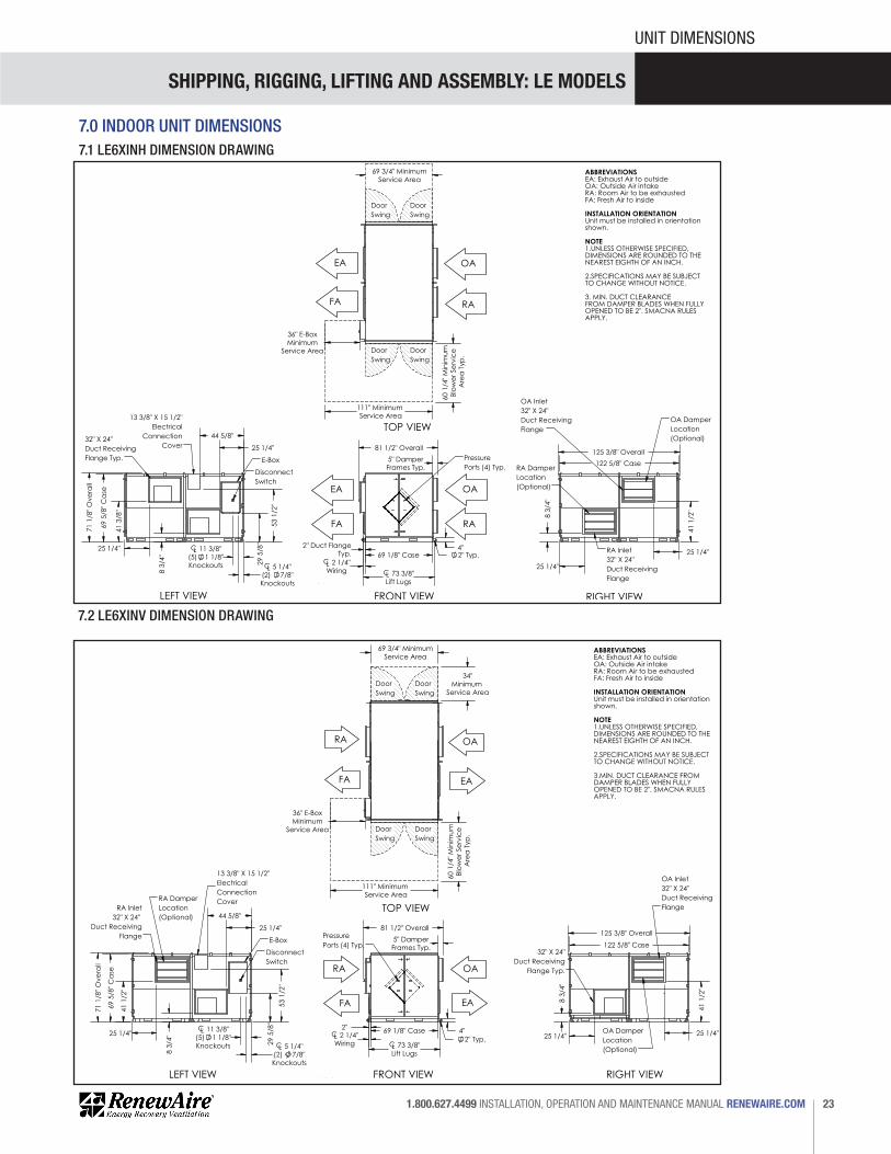
7.0 INDOOR UNIT DIMENSIONS7.1 LE6XINH DIMENSION DRAWING
7.2 LE6XINV DIMENSION DRAWING
FOR THE MOST COM
PLETE AND CURRENT INFORMATION VISIT R
EN
EW
AIR
E.C
OM
LE-SERIES
101
CL 73 3/8"Lift Lugs
69 1/8" Case 2" Duct Flange
Typ. 2" Typ. 4"
5" DamperFrames Typ.
81 1/2" Overall
CL 2 1/4"Wiring
OAEA
PressurePorts (4) Typ.
25 1/4"
41
3/8"
69
5/8"
Ca
se
71
1/8"
Ove
rall
8 3
/4"
29
5/8"
53
1/2"
44 5/8"
25 1/4"
CL 5 1/4"(2) 7/8"Knockouts
CL 11 3/8"(5) 1 1/8"Knockouts
LEFT VIEW
13 3/8" X 15 1/2"Electrical
ConnectionCover
E-Box
DisconnectSwitch
32" X 24"Duct ReceivingFlange Typ.
125 3/8" Overall 122 5/8" Case
25 1/4"
8 3
/4"
25 1/4"
41
1/2"
RIGHT VIEW
OA Inlet32" X 24"Duct ReceivingFlange
RA Inlet32" X 24"Duct ReceivingFlange
RA DamperLocation(Optional)
OA DamperLocation(Optional)
69 3/4" MinimumService Area
60 1
/4" M
inim
um
Blow
er S
ervi
ce
Are
a T
yp.
111" Minimum Service Area
36" E-BoxMinimum
Service Area
FA
Door Swing
Door Swing
Door Swing
Door Swing
FRONT VIEW
TOP VIEW
RA
EA OA
RAFA
Model: LE6XINHDrawing Type: Unit DimensionVersion: MAY18
ABBREVIATIONSEA: Exhaust Air to outsideOA: Outside Air intakeRA: Room Air to be exhaustedFA: Fresh Air to inside
INSTALLATION ORIENTATIONUnit must be installed in orientationshown.
NOTE1.UNLESS OTHERWISE SPECIFIED, DIMENSIONS ARE ROUNDED TO THENEAREST EIGHTH OF AN INCH.
2.SPECIFICATIONS MAY BE SUBJECTTO CHANGE WITHOUT NOTICE.
3. MIN. DUCT CLEARANCEFROM DAMPER BLADES WHEN FULLYOPENED TO BE 2". SMACNA RULES APPLY.
LE6XINH Energy Recovery Ventilator Standard
AIRFLOW CONFIGURATIONAvailable as shown in dimension drawing.
UNIT MOUNTING & APPLICATIONMust be mounted as shown. RA/EA airstream can be switched with OA/FA airstream unless certain options are selected.
FOR THE MOST COM
PLETE AND CURRENT INFORMATION VISIT R
EN
EW
AIR
E.C
OM
LE-SERIES
103
2" Typ. 4"
5" DamperFrames Typ.
81 1/2" Overall
69 1/8" Case
CL 73 3/8"Lift Lugs
2" CL 2 1/4"Wiring
OA
PressurePorts (4) Typ.
RA
69
5/8"
Ca
se
71
1/8"
Ove
rall
8 3
/4"
29
5/8"
5
3 1/
2"
44 5/8"
25 1/4"
CL 5 1/4"(2) 7/8"Knockouts
CL 11 3/8"(5) 1 1/8"Knockouts
25 1/4"
41
1/2"
LEFT VIEW
13 3/8" X 15 1/2"ElectricalConnectionCover
E-Box
DisconnectSwitch
RA Inlet32" X 24"
Duct Receiving Flange
RA DamperLocation(Optional)
125 3/8" Overall 122 5/8" Case
8 3
/4"
25 1/4" 25 1/4"
41
1/2"
RIGHT VIEW
32" X 24"Duct Receiving
Flange Typ.
OA Inlet32" X 24" Duct ReceivingFlange
OA DamperLocation(Optional)
69 3/4" MinimumService Area
60 1
/4" M
inim
um
Blow
er S
ervi
ce
Are
a T
yp.
111" Minimum Service Area
36" E-BoxMinimum
Service Area
34"Minimum
Service Area
FA
Door Swing
Door Swing
Door Swing
Door Swing
FRONT VIEW
TOP VIEW
RA
EA
OA
FA EA
Model: LE6XINVDrawing Type: Unit DimensionVersion: MAY18
ABBREVIATIONSEA: Exhaust Air to outsideOA: Outside Air intakeRA: Room Air to be exhaustedFA: Fresh Air to inside
INSTALLATION ORIENTATIONUnit must be installed in orientationshown.
NOTE1.UNLESS OTHERWISE SPECIFIED, DIMENSIONS ARE ROUNDED TO THENEAREST EIGHTH OF AN INCH.
2.SPECIFICATIONS MAY BE SUBJECTTO CHANGE WITHOUT NOTICE.
3.MIN. DUCT CLEARANCE FROM DAMPER BLADES WHEN FULLYOPENED TO BE 2". SMACNA RULES APPLY.
LE6XINV Energy Recovery Ventilator Standard
AIRFLOW CONFIGURATIONAvailable as shown in dimension drawing.
UNIT MOUNTING & APPLICATIONMust be mounted as shown. RA/EA airstream can be switched with OA/FA airstream unless certain options are selected.

SHIPPING, RIGGING, LIFTING AND ASSEMBLY: LE MODELS
RENEWAIRE.COM INSTALLATION, OPERATION AND MAINTENANCE MANUAL 1.800.627.449924
UNIT DIMENSIONS
7.3 LE8XINH DIMENSION DRAWING
7.4 LE8XINV DIMENSION DRAWING
FOR THE MOST COM
PLETE AND CURRENT INFORMATION VISIT R
EN
EW
AIR
E.C
OM
LE-SERIES
109
5" DamperFrames Typ.
80 3/8" Overall
4"
2" 2" Typ. 69 1/4" Case
CL 73 3/8"Lift LugsCL 2 1/4"
Wiring
Pressure Ports (4) Typ.
41
5/8"
27 3/8" 27 3/8"
8 7/
8"
Typ
.
161 3/8" Case
164 7/8" Overall
OA Inlet48" X 24" Duct ReceivingFlange
RA Inlet48" X 24" Duct ReceivingFlange
OA DamperLocation(Optional)
RA DamperLocation(Optional) 2
9 5/
8"
53
1/2"
27 3/4"
64 5/8"
41
1/8"
27 3/4"
69
5/8"
Ca
se
71
1/8"
Ove
rall
78 1
/2"
Min
imum
Blow
erSe
rvic
eA
rea
Typ
.
111" MinimumService Area
69 3/4"Minimum
Service Area
36" E-BoxMinimum
Service Area
CL 5 1/4"(2) 7/8"Knockouts
CL 11 3/8"(5) 1 1/8Knockouts
48" X 24"Duct Receiving
Flange Typ.
13 3/8" X 15 1/2"Electrical ConnectionCover
E-Box
Disconnect Switch
DoorSwing
DoorSwing
DoorSwing
DoorSwing
RA
EA
FA
OA
FRONT VIEW RIGHT VIEWLEFT VIEW
TOP VIEW
FA
OA
RA
EA
Model: LE8XINHDrawing Type: Unit DimensionVersion: MAY18
ABBREVIATIONSEA: Exhaust Air to outsideOA: Outside Air intakeRA: Room Air to be exhaustedFA: Fresh Air to inside
INSTALLATION ORIENTATIONUnit must be installed in orientationshown.
NOTE1.UNLESS OTHERWISE SPECIFIED, DIMENSIONS ARE ROUNDED TO THENEAREST EIGHTH OF AN INCH.
2.SPECIFICATIONS MAY BE SUBJECTTO CHANGE WITHOUT NOTICE.
3.MIN. DUCT CLEARANCE FROM DAMPER BLADES WHEN FULLYOPENED TO BE 2". SMACNA RULES APPLY.
LE8XINH Energy Recovery Ventilator Standard
AIRFLOW CONFIGURATIONAvailable as shown in dimension drawing.
UNIT MOUNTING & APPLICATIONMust be mounted as shown. RA/EA airstream can be switched with OA/FA airstream unless certain options are selected.
FOR THE MOST COM
PLETE AND CURRENT INFORMATION VISIT R
EN
EW
AIR
E.C
OM
LE-SERIES
111
4"
2" Typ.
2" Duct Flange Typ.
5" DamperFrames Typ.
69 1/4" Case
CL 73 3/8"Lift Lugs
81 1/2" Overall
CL 2 1/4"Wiring
Pressure Ports (4) Typ.
41 3
/4"
Typ
.
26 1/4" 27 5/8"
9" Typ
.
161 3/8" Case 164 7/8" Overall
OA Inlet48" X 24" Duct ReceivingFlange
48" X 24"Duct ReceivingFlange Typ.
OA DamperLocation(Optional)
29
5/8"
53
1/2"
69
5/8"
Ca
se
71
1/8"
Ove
rall
26 1/4" 27 3/4"
64 5/8"
78 1
/2"
Min
imum
Blo
wer
Serv
ice
Are
a
111" MinimumService Area
69 3/4" MinimumService Area
36" E-BoxMinimum
Service Area
CL 5 1/4"(2) 7/8"Knockouts
CL 11 3/8"(5) 1 1/8Knockouts
34"
Min
imum
Serv
ice
Are
a
13 3/8" X 15 1/2"Electrical ConnectionCover
E-Box
Disconnect Switch
RA Inlet48" X 24"
Duct Receiving Flange
RA DamperLocation(Optional)
DoorSwing
DoorSwing
DoorSwing
DoorSwing
RA
EAFA
OA
FRONT VIEW RIGHT VIEWLEFT VIEW
TOP VIEW
FA
OARA
EA
Model: LE8XINVDrawing Type: Unit DimensionVersion: MAY18
ABBREVIATIONSEA: Exhaust Air to outsideOA: Outside Air intakeRA: Room Air to be exhaustedFA: Fresh Air to inside
INSTALLATION ORIENTATIONUnit must be installed in orientationshown.
NOTE1.UNLESS OTHERWISE SPECIFIED, DIMENSIONS ARE ROUNDED TO THENEAREST EIGHTH OF AN INCH.
2.SPECIFICATIONS MAY BE SUBJECTTO CHANGE WITHOUT NOTICE.
3.DUCT CLEARANCE FROM DAMPER BLADES WHEN FULLY OPENED TO BE 2". SMACNA RULES APPLY.
LE8XINV Energy Recovery Ventilator Standard
AIRFLOW CONFIGURATIONAvailable as shown in dimension drawing.
UNIT MOUNTING & APPLICATIONMust be mounted as shown. RA/EA airstream can be switched with OA/FA airstream unless certain options are selected.

SHIPPING, RIGGING, LIFTING AND ASSEMBLY: LE MODELS
25 1.800.627.4499 INSTALLATION, OPERATION AND MAINTENANCE MANUAL RENEWAIRE.COM
UNIT DIMENSIONS
7.5 LE10XINH DIMENSION DRAWING
7.6 LE10XINV DIMENSION DRAWING
FOR THE MOST COM
PLETE AND CURRENT INFORMATION VISIT R
EN
EW
AIR
E.C
OM
LE-SERIES
117
69 1/8" Case 73 3/8"Lift Lugs
4"
80 3/8"Overall
2"Typ.
2"
5" Damper Frames Typ.
CL 2 1/4"Wiring
FRONT VIEW
Pressure Ports (4) Typ. 202 5/8" Case
205 3/8" Overall
41
1/2"
47 1/4" 8
3/4"
Typ
. 47 1/4"
RA Inlet48" X 24"Duct ReceivingFlange
OA Inlet48" X 24"Duct ReceivingFlange
RA DamperLocation(Optional)
OA Damper Location(Optional)
53
1/2"
47 1/4"
84 5/8"
69
5/8"
Ca
se
71
1/8"
Ove
rall
47 1/4"
41
1/8"
29
5/8"
CL 5 1/4"(2) 7/8"Knockouts
CL 11 3/8"(5) 1 1/8"Knockouts
LEFT VIEW
E-Box
DisconnectSwitch
13 3/8" X 15 1/2"Electrical
ConnectionCover
48" X 24"Duct ReceivingFlange Typ.
69 3/4"Minimum
Service Area
36" E-BoxMinimum
Service Area
79 7
/8"
Min
imum
Blow
erSe
rvic
eA
rea
Typ
.
111" MinimumService Area
DoorSwing
DoorSwing
DoorSwing
DoorSwing
RAFA
OAEA
TOP VIEW
RIGHT VIEW
FA
OA
RA
EA
Model: LE10XINHDrawing Type: Unit DimensionVersion: MAY18
ABBREVIATIONSEA: Exhaust Air to outsideOA: Outside Air intakeRA: Room Air to be exhaustedFA: Fresh Air to inside
INSTALLATION ORIENTATIONUnit must be installed in orientationshown.
NOTE1. UNLESS OTHERWISE SPECIFIED,DIMENSIONS ARE ROUNDED TO THE NEAREST EIGHTH OF AN INCH.
2. SPECIFICATIONS MAY BE SUBJECT TO CHANGE WITHOUT NOTICE.
3. MIN. DUCT CLEARANCE FROM DAMPER BLADES WHEN FULLYOPENED TO BE 2". SMACNA RULES APPLY.
LE10XINH Energy Recovery Ventilator Standard
AIRFLOW CONFIGURATIONAvailable as shown in dimension drawing.
UNIT MOUNTING & APPLICATIONMust be mounted as shown. RA/EA airstream can be switched with OA/FA airstream unless certain options are selected.
FOR THE MOST COM
PLETE AND CURRENT INFORMATION VISIT R
EN
EW
AIR
E.C
OM
LE-SERIES
119
69 1/8" Case
73 3/8"Lift Lugs
81 3/8"Overall
4" 2" Typ.
5" DamperFrames Typ.
2" DuctFlange Typ.CL 2 1/4"
Wiring
FRONT VIEW
PressurePorts (4) Typ.
41
5/8"
47 3/8" 47 1/4"
8 7
/8"
202 5/8" Case 205 3/8" Overall
48" X 24"Duct ReceivingFlange Typ.
OA Inlet48" X 24" Duct ReceivingFlange
OA DamperLocation(Optional)
53
1/2"
47 1/4"
84 5/8"
71
1/8"
Ove
rall
69
5/8"
Ca
se
8 7
/8"
47 3/8"
41
5/8"
29
5/8"
CL 11 3/8"(5) 1 1/8"Knockouts
CL 5 1/4"(2) 7/8"Knockouts
E-BoxDisconnect
Switch
13 3/8" X 15 1/2"Electrical
ConnectionCover
RA Inlet48" X 24"
Duct Receiving Flange
RA DamperLocation(Optional)
34" M
inim
umSe
rvic
e A
rea
69 3/4"Minimum
Service Area
79 7
/8"
Min
imum
Blow
erSe
rvic
e A
rea
111" MinimumService Area
36" E-BoxMinimum
Service Area
DoorSwing
DoorSwing
DoorSwing
DoorSwing
RA
FA EA
OA
TOP VIEW
LEFT VIEW RIGHT VIEW
RA
FA
OA
EA
Model: LE10XINVDrawing Type: Unit DimensionVersion: MAY18
ABBREVIATIONSEA: Exhaust Air to outsideOA: Outside Air intakeRA: Room Air to be exhaustedFA: Fresh Air to inside
INSTALLATION ORIENTATIONUnit must be installed in orientationshown.
NOTE1. UNLESS OTHERWISE SPECIFIED,DIMENSIONS ARE ROUNDED TO THE NEAREST EIGHTH OF AN INCH.
2. SPECIFICATIONS MAY BE SUBJECT TO CHANGE WITHOUT NOTICE.
3.DUCT CLEARANCE FROM DAMPER BLADE WHEN FULLYOPENED TO BE 2". SMACNA RULES APPLY.
LE10XINV Energy Recovery Ventilator Standard
AIRFLOW CONFIGURATIONAvailable as shown in dimension drawing.
UNIT MOUNTING & APPLICATIONMust be mounted as shown. RA/EA airstream can be switched with OA/FA airstream unless certain options are selected.

SHIPPING, RIGGING, LIFTING AND ASSEMBLY: LE MODELS
RENEWAIRE.COM INSTALLATION, OPERATION AND MAINTENANCE MANUAL 1.800.627.449926
CORNER WEIGHTS
8.0 LE6X CORNER WEIGHTS
73.5"Lifting Lug
LR RR
LF RF
119.
5" L
iftin
g Lu
gCORNER WEIGHTS AT LIFTING LUGS
BASIC UNIT WEIGHTS (lbs.)
Motors UNIT LF LR RR RF3 HP 2086 579 580 464 463
2100 583 585 466 465
2218 625 630 483 480
5 HP
7.5 HP
Options UNIT LF LR RR RF
ADDITIONAL WEIGHTS FOR OPTIONS (lbs.)
Double Wall 418 105 104 104 105
12 10 1 0 1
47 11 1 10 25
58 2 2 27 27
VFDs
RA or EA Damper
OA or FA Damper
Total Selected Weights
Add the additional weights for options to the Basic Unit weights determined by motor size to determine Unit and Corner weights for a specific unit.Corner weights shown above include weatherhoods INSIDE THE UNIT, as shipped.
"B"
"A"
Center of gravity: A=32" B=61" (+/- 2")
1/30/2014 MFSPECIFICATIONS SUBJECT TO CHANGE WITHOUT NOTICE.
RenewAire LLC
Do not scale drawing
LE-6X-RT_CORNER_WEIGHTS_MAY18.dwg
LE-6X-RT Corner WeightsSheet 1 of 4
73.5"Lifting Lug
LR RR
59.3
" Lift
ing
Lug
REAR MODULE WEIGHTS AT LIFTING LUGS
BASIC MODULE WEIGHTS (lbs.)
Motors UNIT LF LR RR RF3 HP 1017 252 190 247 328
1024 253 190 249 332
1083 268 190 260 365
5 HP
7.5 HP
Options UNIT LF LR RR RF
ADDITIONAL WEIGHTS FOR OPTIONS (lbs.)
Double Wall 209 64 40 40 64
0 0 0 0 0
0 0 0 0 0
27 27
VFDs
RA or EA Damper
OA or FA Damper
Total Selected Weights
Add the additional weights for options to the Basic Unit weights determined by motor size to determine Unit and Corner weights for a specific unit.
58 2 2
Corner weights shown above include weatherhoods INSIDE THE UNIT, as shipped.
"A"
"B"
Door End
Back ModuleLF RF
Center of gravity: A=42" B=25" (+/- 2")
1/30/2014 MFSPECIFICATIONS SUBJECT TO CHANGE WITHOUT NOTICE.
RenewAire LLC
Do not scale drawing
LE-6X-RT_CORNER_WEIGHTS_MAY18.dwg
LE-6X-RT Back ModuleCorner Weights Sheet 4 of 4
73.5"Lifting Lug
LF RF
59.3
" Lift
ing
Lug
FRONT MODULE WEIGHTS AT LIFTING LUGS
BASIC MODULE WEIGHTS (lbs.)
Motors UNIT LF LR RR RF3 HP 1068 281 243 253 292
1076 283 245 254 294
1135 308 258 259 309
5 HP
7.5 HP
Options UNIT LF LR RR RF
ADDITIONAL WEIGHTS FOR OPTIONS (lbs.)
Double Wall 209 64 40 40 64
12 10 1 0 1
47 11 1 10 25
58 2 2 27 27
VFDs
RA or EA Damper
OA or FA Damper
Total Selected Weights
Add the additional weights for options to the Basic Unit weights determined by motor size to determine Unit and Corner weights for a specific unit.Corner weights shown above include weatherhoods INSIDE THE UNIT, as shipped.
"B"
"A"
Door EndCenter of gravity: A=37" B=27" (+/- 2")
Front ModuleLR RR
1/30/2014 MFSPECIFICATIONS SUBJECT TO CHANGE WITHOUT NOTICE.
RenewAire LLC
Do not scale drawing
LE-6X-RT_CORNER_WEIGHTS_MAY18.dwg
LE-6X-RT Front ModuleCorner Weights Sheet 3 of 4
73.5"Lifting Lug
LR RR
LF RF
119.
5" L
iftin
g Lu
gCORNER WEIGHTS AT LIFTING LUGS
BASIC UNIT WEIGHTS (lbs.)
Motors UNIT LF LR RR RF3 HP 2086 579 580 464 463
2100 583 585 466 465
2218 625 630 483 480
5 HP
7.5 HP
Options UNIT LF LR RR RF
ADDITIONAL WEIGHTS FOR OPTIONS (lbs.)
Double Wall 418 105 104 104 105
12 10 1 0 1
47 11 1 10 25
58 2 2 27 27
VFDs
RA or EA Damper
OA or FA Damper
Total Selected Weights
Add the additional weights for options to the Basic Unit weights determined by motor size to determine Unit and Corner weights for a specific unit.Corner weights shown above include weatherhoods INSIDE THE UNIT, as shipped.
"B"
"A"
Center of gravity: A=32" B=61" (+/- 2")
1/30/2014 MFSPECIFICATIONS SUBJECT TO CHANGE WITHOUT NOTICE.
RenewAire LLC
Do not scale drawing
LE-6X-RT_CORNER_WEIGHTS_MAY18.dwg
LE-6X-RT Corner WeightsSheet 1 of 4
8.1 LE6XRT CORNER WEIGHTS
73.5"Lifting Lug
LR RR
59.3
" Lift
ing
Lug
REAR MODULE WEIGHTS AT LIFTING LUGS
BASIC MODULE WEIGHTS (lbs.)
Motors UNIT LF LR RR RF3 HP 1017 252 190 247 328
1024 253 190 249 332
1083 268 190 260 365
5 HP
7.5 HP
Options UNIT LF LR RR RF
ADDITIONAL WEIGHTS FOR OPTIONS (lbs.)
Double Wall 209 64 40 40 64
0 0 0 0 0
0 0 0 0 0
27 27
VFDs
RA or EA Damper
OA or FA Damper
Total Selected Weights
Add the additional weights for options to the Basic Unit weights determined by motor size to determine Unit and Corner weights for a specific unit.
58 2 2
Corner weights shown above include weatherhoods INSIDE THE UNIT, as shipped.
"A"
"B"
Door End
Back ModuleLF RF
Center of gravity: A=42" B=25" (+/- 2")
1/30/2014 MFSPECIFICATIONS SUBJECT TO CHANGE WITHOUT NOTICE.
RenewAire LLC
Do not scale drawing
LE-6X-RT_CORNER_WEIGHTS_MAY18.dwg
LE-6X-RT Back ModuleCorner Weights Sheet 4 of 4
73.5"Lifting Lug
LF RF
59.3
" Lift
ing
Lug
FRONT MODULE WEIGHTS AT LIFTING LUGS
BASIC MODULE WEIGHTS (lbs.)
Motors UNIT LF LR RR RF3 HP 1068 281 243 253 292
1076 283 245 254 294
1135 308 258 259 309
5 HP
7.5 HP
Options UNIT LF LR RR RF
ADDITIONAL WEIGHTS FOR OPTIONS (lbs.)
Double Wall 209 64 40 40 64
12 10 1 0 1
47 11 1 10 25
58 2 2 27 27
VFDs
RA or EA Damper
OA or FA Damper
Total Selected Weights
Add the additional weights for options to the Basic Unit weights determined by motor size to determine Unit and Corner weights for a specific unit.Corner weights shown above include weatherhoods INSIDE THE UNIT, as shipped.
"B"
"A"
Door EndCenter of gravity: A=37" B=27" (+/- 2")
Front ModuleLR RR
1/30/2014 MFSPECIFICATIONS SUBJECT TO CHANGE WITHOUT NOTICE.
RenewAire LLC
Do not scale drawing
LE-6X-RT_CORNER_WEIGHTS_MAY18.dwg
LE-6X-RT Front ModuleCorner Weights Sheet 3 of 4

SHIPPING, RIGGING, LIFTING AND ASSEMBLY: LE MODELS
27 1.800.627.4499 INSTALLATION, OPERATION AND MAINTENANCE MANUAL RENEWAIRE.COM
CORNER WEIGHTS
73.5"Lifting Lug
LR RR
LF RF
119.
5" L
iftin
g Lu
g
CORNER WEIGHTS AT LIFTING LUGS
BASIC UNIT WEIGHTS (lbs.)
Motors UNIT LF LR RR RF3 HP 1975 565 550 424 436
1989 570 555 426 438
2106 611 600 443 452
5 HP
7.5 HP
Options UNIT LF LR RR RF
ADDITIONAL WEIGHTS FOR OPTIONS (lbs.)
Double Wall 418 105 104 104 105
12 10 1 0 1
47 3 1 14 29
47 1 3 29 1
VFDs
RA or EA Damper
OA or FA Damper
Total Selected Weights"B"
"A"
Add the additional weights for options to the Basic Unit weights determined by motor size to determine Unit and Corner weights for a specific unit.Center of gravity: A=32" B=61" (+/- 2")
1/30/2014 MFSPECIFICATIONS SUBJECT TO CHANGE WITHOUT NOTICE.
RenewAire LLC
Do not scale drawing
LE-6X-INH_CORNER_WEIGHTS_MAY18.dwg
LE-6X-INH Corner WeightsSheet 1 of 4
73.5"Lifting Lug
LR RR
59.3
" Lift
ing
Lug
REAR MODULE WEIGHTS AT LIFTING LUGS
BASIC MODULE WEIGHTS (lbs.)
Motors UNIT LF LR RR RF3 HP 943 229 174 233 306
950 230 174 235 310
1009 245 175 246 343
5 HP
7.5 HP
Options UNIT LF LR RR RF
ADDITIONAL WEIGHTS FOR OPTIONS (lbs.)
Double Wall 209 64 40 40 64
0 0 0 0 0
0 0 0 0 0
29 14
VFDs
RA or EA Damper
OA or FA Damper
Total Selected Weights
Add the additional weights for options to the Basic Unit weights determined by motor size to determine Unit and Corner weights for a specific unit.
47 1 3
"A"
"B"
Door End
LF RF
Center of gravity: A=42" B=25" (+/- 2")
1/30/2014 MFSPECIFICATIONS SUBJECT TO CHANGE WITHOUT NOTICE.
RenewAire LLC
Do not scale drawing
LE-6X-INH_CORNER_WEIGHTS_MAY18.dwg
LE-6X-INH Rear ModuleCorner Weights Sheet 4 of 4
8.2 LE6XINH CORNER WEIGHTS 8.3 LE6XINV CORNER WEIGHTS
73.5"Lifting Lug
LF RF
59.3
" Lift
ing
Lug
FRONT MODULE WEIGHTS AT LIFTING LUGS
BASIC MODULE WEIGHTS (lbs.)
Motors UNIT LF LR RR RF3 HP 1032 307 261 213 250
1039 310 263 214 252
1099 338 277 218 266
5 HP
7.5 HP
Options UNIT LF LR RR RF
ADDITIONAL WEIGHTS FOR OPTIONS (lbs.)
Double Wall 209 64 40 40 64
12 10 1 0 1
47 3 1 14 29
0 0 0 0 0
VFDs
RA or EA Damper
OA or FA Damper
Total Selected Weights
"B"
"A"
Door End
Add the additional weights for options to the Basic Unit weights determined by motor size to determine Unit and Corner weights for a specific unit.Center of gravity: A=33" B=27" (+/- 2")
LR RR
1/30/2014 MFSPECIFICATIONS SUBJECT TO CHANGE WITHOUT NOTICE.
RenewAire LLC
Do not scale drawing
LE-6X-INH_CORNER_WEIGHTS_MAY18.dwg
LE-6X-INH Front ModuleCorner Weights Sheet 3 of 4
73.5"Lifting Lug
LR RR
LF RF
119.
5" L
iftin
g Lu
g
CORNER WEIGHTS AT LIFTING LUGS
BASIC UNIT WEIGHTS (lbs.)
Motors UNIT LF LR RR RF3 HP 1984 569 433 424 558
1998 575 434 425 563
2116 626 442 434 614
5 HP
7.5 HP
Motors UNIT LF LR RR RF
ADDITIONAL WEIGHTS FOR OPTIONS (lbs.)
Double Wall 418 105 104 104 105
12 10 1 0 1
47
47
VFDs
RA or EA Damper
OA or FA Damper
Total Selected Weights
Add the additional weights for options to the Basic Unit weights determined by motor size to determine Unit and Corner weights for a specific unit.
1 3 29 14
14 29 3 1
"B"
"A"
Center of gravity: A=32" B=57" (+/- 2")
1/30/2014 MFSPECIFICATIONS SUBJECT TO CHANGE WITHOUT NOTICE.
RenewAire LLC
Do not scale drawing
LE-6X-INV_CORNER_WEIGHTS_MAY18.dwg
LE-6X-INV Corner WeightsSheet 1 of 4
73.5"Lifting Lug
LR RR
59.3
" Lift
ing
Lug
REAR MODULE WEIGHTS AT LIFTING LUGS
BASIC MODULE WEIGHTS (lbs.)
Motors UNIT LF LR RR RF3 HP
715 207 158 151 1985 HP
7.5 HP
Options UNIT LF LR RR RF
ADDITIONAL WEIGHTS FOR OPTIONS (lbs.)
Double Wall 209 64 40 40 64
0 0 0 0 0
3 1
VFDs
Total Selected Weights
Add the additional weights for options to the Basic Unit weights determined by motor size to determine Unit and Corner weights for a specific unit.
47 14 29
29 1447 1 3
Back Module
Door End
"A"
"B"
LF RF
Center of gravity: A=36" B=23" (+/- 2")
OA or FA Damper
RA or EA Damper
1/30/2014 MFSPECIFICATIONS SUBJECT TO CHANGE WITHOUT NOTICE.
RenewAire LLC
Do not scale drawing
LE-6X-INV_CORNER_WEIGHTS_MAY18.dwg
LE-6X-INV Back ModuleCorner Weights Sheet 4 of 4
73.5"Lifting Lug
LF RF
59.3
" Lift
ing
Lug
FRONT MODULE WEIGHTS AT LIFTING LUGS
BASIC MODULE WEIGHTS (lbs.)
Motors UNIT LF LR RR RF3 HP 1269 341 304 294 330
1283 345 306 297 335
1401 387 323 314 376
5 HP
7.5 HP
Options UNIT LF LR RR RF
ADDITIONAL WEIGHTS FOR OPTIONS (lbs.)
Double Wall 209 64 40 40 64
12 10 3 0 1
0 0 0 0 0
0 0 0 0 0
VFDs
Total Selected Weights
Add the additional weights for options to the Basic Unit weights determined by motor size to determine Unit and Corner weights for a specific unit.
Front Module
Door End
"B"
"A"
Center of gravity: A=36" B=27" (+/- 2")
LR RR
OA or FA Damper
RA or EA Damper
1/30/2014 MFSPECIFICATIONS SUBJECT TO CHANGE WITHOUT NOTICE.
RenewAire LLC
Do not scale drawing
LE-6X-INV_CORNER_WEIGHTS_MAY18.dwg
LE-6X-INV Front ModuleCorner Weights Sheet 3 of 4

SHIPPING, RIGGING, LIFTING AND ASSEMBLY: LE MODELS
RENEWAIRE.COM INSTALLATION, OPERATION AND MAINTENANCE MANUAL 1.800.627.449928
CORNER WEIGHTS
9.0 LE8X CORNER WEIGHTS9.1 LE8XRT CORNER WEIGHTS
73.5" Lifting Lug
LR RR
LF RF
159.
5" L
iftin
g Lu
g
BASIC UNIT WEIGHTS (lbs.)
Motors UNIT LF LR RR RF3 HP 2625 753 680 568 624
2645 745 737 578 585
2763 790 780 593 600
5 HP
7.5 HP
Options UNIT LF LR RR RF
ADDITIONAL WEIGHTS FOR OPTIONS (lbs.)
Double Wall 524 131 131 131 131
12 10 1 0 1
66 14 1 12 39
88 2 2 42 42
VFDs
RA or EA Damper
OA or FA Damper
Total Selected Weights
Add the additional weights for options to the Basic Unit weights determined by motor size to determine Unit and Corner weights for a specific unit.
CORNER WEIGHTS AT LIFTING LUGS
Corner weights shown above include weatherhoods INSIDE THE UNIT, as shipped.
"B"
"A"
Center of gravity: A=32" B=80" (+/- 2")
1/31/2014 MFSPECIFICATIONS SUBJECT TO CHANGE WITHOUT NOTICE.
RenewAire LLC
Do not scale drawing
LE-8XRT_CORNER_WEIGHTS_MAY18.dwg
LE-8X-RT Corner WeightsSheet 1 of 473.5" Lifting Lug
RF LF
RR LR
79.5
" Lift
ing
Lug
BASIC UNIT WEIGHTS (lbs.)
Motors UNIT LF LR RR RF3 HP 1320 322 244 325 429
1327 323 244 327 433
1386 330 248 347 460
5 HP
7.5 HP
Options UNIT LF LR RR RF
ADDITIONAL WEIGHTS FOR OPTIONS (lbs.)
Double Wall 263 78 54 54 78
0 0 0 0 0
0 0 0 0 0
88 2 2 42 42
VFDs
RA or EA Damper
OA or FA Damper
Total Selected Weights
Add the additional weights for options to the Basic Module weights determined by motor size to determine Module and Corner weights for a specific unit.
BACK MODULE CORNER WEIGHTS AT LIFTING LUGS
Corner weights shown above include weatherhoods INSIDE THE UNIT, as shipped.
"A"
"B"
Door End
Center of gravity: A=33" B=32-3/4" (+/- 2")
1/31/2014 MFSPECIFICATIONS SUBJECT TO CHANGE WITHOUT NOTICE.
RenewAire LLC
Do not scale drawing
LE-8XRT_CORNER_WEIGHTS_MAY18.dwg
LE-8X-RT Back ModuleCorner Weights Sheet 4 of 4
73.5" Lifting Lug
LF RF
79.5
" Lift
ing
Lug
BASIC MODULE WEIGHTS (lbs.)
Motors UNIT LF LR RR RF3 HP 1311 412 301 252 346
1318 416 302 252 348
1377 448 313 253 363
5 HP
7.5 HP
Motors UNIT LF LR RR RF
ADDITIONAL WEIGHTS FOR OPTIONS (lbs.)
Double Wall 263 78 53 53 78
12 10 1 0 1
66 14 1 12 39
88 2 2 42 42
VFDs
RA or EA Damper
OA or FA Damper
Total Selected Weights
Add the additional weights for options to the Basic Module weights determined by motor size to determine Module and Corner weights for a specific unit.
FRONT MODULE CORNER WEIGHTS AT LIFTING LUGS
LR RR
Corner weights shown above include weatherhoods INSIDE THE UNIT, as shipped.
"B"
"A"
Front Module
Door End
Center of gravity: A=33" B=33" (+/- 2")
1/31/2014 MFSPECIFICATIONS SUBJECT TO CHANGE WITHOUT NOTICE.
RenewAire LLC
Do not scale drawing
LE-8XRT_CORNER_WEIGHTS_MAY18.dwg
LE-8X-RT Front ModuleCorner Weights Sheet 3 of 4
73.5" Lifting Lug
LR RR
LF RF
159.
5" L
iftin
g Lu
g
BASIC UNIT WEIGHTS (lbs.)
Motors UNIT LF LR RR RF3 HP 2625 753 680 568 624
2645 745 737 578 585
2763 790 780 593 600
5 HP
7.5 HP
Options UNIT LF LR RR RF
ADDITIONAL WEIGHTS FOR OPTIONS (lbs.)
Double Wall 524 131 131 131 131
12 10 1 0 1
66 14 1 12 39
88 2 2 42 42
VFDs
RA or EA Damper
OA or FA Damper
Total Selected Weights
Add the additional weights for options to the Basic Unit weights determined by motor size to determine Unit and Corner weights for a specific unit.
CORNER WEIGHTS AT LIFTING LUGS
Corner weights shown above include weatherhoods INSIDE THE UNIT, as shipped.
"B"
"A"
Center of gravity: A=32" B=80" (+/- 2")
1/31/2014 MFSPECIFICATIONS SUBJECT TO CHANGE WITHOUT NOTICE.
RenewAire LLC
Do not scale drawing
LE-8XRT_CORNER_WEIGHTS_MAY18.dwg
LE-8X-RT Corner WeightsSheet 1 of 4
73.5" Lifting Lug
RF LF
RR LR
79.5
" Lift
ing
Lug
BASIC UNIT WEIGHTS (lbs.)
Motors UNIT LF LR RR RF3 HP 1320 322 244 325 429
1327 323 244 327 433
1386 330 248 347 460
5 HP
7.5 HP
Options UNIT LF LR RR RF
ADDITIONAL WEIGHTS FOR OPTIONS (lbs.)
Double Wall 263 78 54 54 78
0 0 0 0 0
0 0 0 0 0
88 2 2 42 42
VFDs
RA or EA Damper
OA or FA Damper
Total Selected Weights
Add the additional weights for options to the Basic Module weights determined by motor size to determine Module and Corner weights for a specific unit.
BACK MODULE CORNER WEIGHTS AT LIFTING LUGS
Corner weights shown above include weatherhoods INSIDE THE UNIT, as shipped.
"A"
"B"
Door End
Center of gravity: A=33" B=32-3/4" (+/- 2")
1/31/2014 MFSPECIFICATIONS SUBJECT TO CHANGE WITHOUT NOTICE.
RenewAire LLC
Do not scale drawing
LE-8XRT_CORNER_WEIGHTS_MAY18.dwg
LE-8X-RT Back ModuleCorner Weights Sheet 4 of 4
73.5" Lifting Lug
LF RF
79.5
" Lift
ing
Lug
BASIC MODULE WEIGHTS (lbs.)
Motors UNIT LF LR RR RF3 HP 1311 412 301 252 346
1318 416 302 252 348
1377 448 313 253 363
5 HP
7.5 HP
Motors UNIT LF LR RR RF
ADDITIONAL WEIGHTS FOR OPTIONS (lbs.)
Double Wall 263 78 53 53 78
12 10 1 0 1
66 14 1 12 39
88 2 2 42 42
VFDs
RA or EA Damper
OA or FA Damper
Total Selected Weights
Add the additional weights for options to the Basic Module weights determined by motor size to determine Module and Corner weights for a specific unit.
FRONT MODULE CORNER WEIGHTS AT LIFTING LUGS
LR RR
Corner weights shown above include weatherhoods INSIDE THE UNIT, as shipped.
"B"
"A"
Front Module
Door End
Center of gravity: A=33" B=33" (+/- 2")
1/31/2014 MFSPECIFICATIONS SUBJECT TO CHANGE WITHOUT NOTICE.
RenewAire LLC
Do not scale drawing
LE-8XRT_CORNER_WEIGHTS_MAY18.dwg
LE-8X-RT Front ModuleCorner Weights Sheet 3 of 4
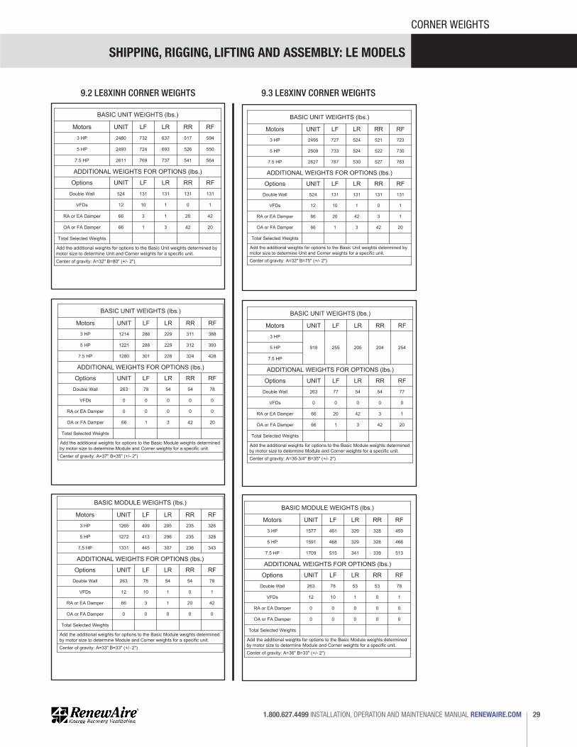
SHIPPING, RIGGING, LIFTING AND ASSEMBLY: LE MODELS
29 1.800.627.4499 INSTALLATION, OPERATION AND MAINTENANCE MANUAL RENEWAIRE.COM
CORNER WEIGHTS
9.2 LE8XINH CORNER WEIGHTS 9.3 LE8XINV CORNER WEIGHTS
73.5" Lifting Lug
LR RR
LF RF
159.
5" L
iftin
g Lu
g
BASIC UNIT WEIGHTS (lbs.)
Motors UNIT LF LR RR RF3 HP 2480 732 637 517 594
2493 724 693 526 550
2611 769 737 541 564
5 HP
7.5 HP
Options UNIT LF LR RR RF
ADDITIONAL WEIGHTS FOR OPTIONS (lbs.)
Double Wall 524 131 131 131 131
12 10 1 0 1
66 3 1 20 42
66 1 3 42 20
VFDs
RA or EA Damper
OA or FA Damper
Total Selected Weights
Add the additional weights for options to the Basic Unit weights determined by motor size to determine Unit and Corner weights for a specific unit.
CORNER WEIGHTS AT LIFTING LUGS
"B"
"A"
Center of gravity: A=32" B=80" (+/- 2")
1/31/2014 MFSPECIFICATIONS SUBJECT TO CHANGE WITHOUT NOTICE.
RenewAire LLC
Do not scale drawing
LE-8X-INH_CORNER_WEIGHTS_MAY18.dwg
LE-8X-INH Corner WeightsSheet 1 of 4
73.5" Lifting Lug
RF LF
RR LR
79.5
" Lift
ing
Lug
BASIC UNIT WEIGHTS (lbs.)
Motors UNIT LF LR RR RF3 HP 1214 286 229 311 388
1221 288 229 312 393
1280 301 228 324 428
5 HP
7.5 HP
Options UNIT LF LR RR RF
ADDITIONAL WEIGHTS FOR OPTIONS (lbs.)
Double Wall 263 78 54 54 78
0 0 0 0 0
0 0 0 0 0
66 1 3 42 20
VFDs
RA or EA Damper
OA or FA Damper
Total Selected Weights
Add the additional weights for options to the Basic Module weights determined by motor size to determine Module and Corner weights for a specific unit.
BACK MODULE CORNER WEIGHTS AT LIFTING LUGS
"A"
"B"
Door End
Center of gravity: A=37" B=35" (+/- 2")
Back Module
1/31/2014 MFSPECIFICATIONS SUBJECT TO CHANGE WITHOUT NOTICE.
RenewAire LLC
Do not scale drawing
LE-8X-INH_CORNER_WEIGHTS_MAY18.dwg
LE-8X-INH Back Module Corner Weights Sheet 4 of 4
73.5" Lifting Lug
LF RF
79.5
" Lift
ing
Lug
BASIC MODULE WEIGHTS (lbs.)
Motors UNIT LF LR RR RF3 HP 1265 409 295 235 326
1272 413 296 235 328
1331 445 307 236 343
5 HP
7.5 HP
Options UNIT LF LR RR RF
ADDITIONAL WEIGHTS FOR OPTIONS (lbs.)
Double Wall 263 78 54 54 78
12 10 1 0 1
66 3 1 20 42
0 0 0 0 0
VFDs
RA or EA Damper
OA or FA Damper
Total Selected Weights
Add the additional weights for options to the Basic Module weights determined by motor size to determine Module and Corner weights for a specific unit.
FRONT MODULE CORNER WEIGHTS AT LIFTING LUGS
LR RR
"B"
"A"
Front Module
Door End
Center of gravity: A=33" B=33" (+/- 2")
1/31/2014 MFSPECIFICATIONS SUBJECT TO CHANGE WITHOUT NOTICE.
RenewAire LLC
Do not scale drawing
LE-8X-INH_CORNER_WEIGHTS_MAY18.dwg
LE-8X-INH Front Module Corner Weights Sheet 3 of 4
73.5" Lifting Lug
LR RR
LF RF
159.
5" L
iftin
g Lu
g
BASIC UNIT WEIGHTS (lbs.)
Motors UNIT LF LR RR RF3 HP 2495 727 524 521 723
2509 733 524 522 730
2627 787 530 527 783
5 HP
7.5 HP
Options UNIT LF LR RR RF
ADDITIONAL WEIGHTS FOR OPTIONS (lbs.)
Double Wall 524 131 131 131 131
12 10 1 0 1
66 20 42 3 1
66 1 3 42 20
VFDs
RA or EA Damper
OA or FA Damper
Total Selected Weights
Add the additional weights for options to the Basic Unit weights determined by motor size to determine Unit and Corner weights for a specific unit.
CORNER WEIGHTS AT LIFTING LUGS
"B"
"A"
Center of gravity: A=32" B=75" (+/- 2")
1/31/2014 MFSPECIFICATIONS SUBJECT TO CHANGE WITHOUT NOTICE.
RenewAire LLC
Do not scale drawing
LE-8X-INV_CORNER_WEIGHTS_MAY18.dwg
LE-8X-INV Corner WeightsSheet 1 of 4
73.5" Lifting Lug
RF LF
RR LR
79.5
" Lift
ing
Lug
BASIC UNIT WEIGHTS (lbs.)
Motors UNIT LF LR RR RF3 HP
918 255 205 204 2545 HP
7.5 HP
Options UNIT LF LR RR RF
ADDITIONAL WEIGHTS FOR OPTIONS (lbs.)
Double Wall 263 77 54 54 77
0 0 0 0 0
66 20 42 3 1
66 1 3 42 20
VFDs
RA or EA Damper
OA or FA Damper
Total Selected Weights
Add the additional weights for options to the Basic Module weights determined by motor size to determine Module and Corner weights for a specific unit.
BACK MODULE CORNER WEIGHTS AT LIFTING LUGS
Door End
Back Module
"A"
"B"
Center of gravity: A=36-3/4" B=35" (+/- 2")
1/31/2014 MFSPECIFICATIONS SUBJECT TO CHANGE WITHOUT NOTICE.
RenewAire LLC
Do not scale drawing
LE-8X-INV_CORNER_WEIGHTS_MAY18.dwg
LE-8X-INV Rear ModuleCorner Weights Sheet 4 of 4
73.5" Lifting Lug
LF RF
79.5
" Lift
ing
Lug
BASIC MODULE WEIGHTS (lbs.)
Motors UNIT LF LR RR RF3 HP 1577 461 329 328 459
1591 468 329 328 466
1709 515 341 339 513
5 HP
7.5 HP
Options UNIT LF LR RR RF
ADDITIONAL WEIGHTS FOR OPTIONS (lbs.)
Double Wall 263 78 53 53 78
12 10 1 0 1
0 0 0 0 0
0 0 0 0 0
VFDs
RA or EA Damper
OA or FA Damper
Total Selected Weights
Add the additional weights for options to the Basic Module weights determined by motor size to determine Module and Corner weights for a specific unit.
FRONT MODULE CORNER WEIGHTS AT LIFTING LUGS
LR RR
Door End
Front Module
"B"
"A"
Center of gravity: A=36" B=33" (+/- 2")
1/31/2014 MFSPECIFICATIONS SUBJECT TO CHANGE WITHOUT NOTICE.
RenewAire LLC
Do not scale drawing
LE-8X-INV_CORNER_WEIGHTS_MAY18.dwg
LE-8X-INV Front ModuleCorner Weights Sheet 3 of 4

SHIPPING, RIGGING, LIFTING AND ASSEMBLY: LE MODELS
RENEWAIRE.COM INSTALLATION, OPERATION AND MAINTENANCE MANUAL 1.800.627.449930
CORNER WEIGHTS
10.0 LE10X CORNER WEIGHTS10.1 LE10XRT CORNER WEIGHTS
73.5" Lifting Lug
LR RR
LF RF
194.
5" L
iftin
g Lu
g
BASIC UNIT WEIGHTS (lbs.)
Motors UNIT LF LR RR RF3 HP 3031 842 841 674 674
3045 847 846 676 676
3163 892 890 690 691
5 HP
7.5 HP
Options UNIT LF LR RR RF
ADDITIONAL WEIGHTS FOR OPTIONS (lbs.)
Double Wall 626 155 158 158 155
12 10 1 0 1
66 14 1 12 39
88 2 2 42 42
VFDs
RA or EA Damper
OA or FA Damper
Total Selected Weights
Add the additional weights for options to the Basic Unit weights determined by motor size to determine Unit and Corner weights for a specific unit.
CORNER WEIGHTS AT LIFTING LUGS
"B"
"A"
10 HP 3201 906 904 695 696
Center of gravity: A=32" B= 101" (+/- 2")
11/24/2015 KMCSPECIFICATIONS SUBJECT TO CHANGE WITHOUT NOTICE.
RenewAire LLC
Do not scale drawing
LE10X-RT_CORNER_WEIGHTS_MAY18.dwg
LE10X-RT Corner WeightsSheet 1 of 473.5" Lifting Lug
RF LF
RR LR
99.5
" Lift
ing
Lug
BACK MODULE CORNER WEIGHTS AT LIFTING LUGS
"A"
"B"
Door End
Back Module
BASIC UNIT WEIGHTS (lbs.)
Motors UNIT LF LR RR RF3 HP 1539 330 334 440 435
1546 354 346 419 427
1605 363 348 437 456
5 HP
7.5 HP
Options UNIT LF LR RR RF
ADDITIONAL WEIGHTS FOR OPTIONS (lbs.)
Double Wall 313 91 66 66 91
0 0 0 0 0
0 0 0 0 0
88 2 2 42 42
VFDs
RA or EA Damper
OA or FA Damper
Total Selected Weights
Add the additional weights for options to the Basic Unit weights determined by motor size to determine Unit and Corner weights for a specific unit.
10 HP 1624 367 349 443 466
Center of gravity: A=41" B= 48" (+/- 2")
11/24/2015SPECIFICATIONS SUBJECT TO CHANGE WITHOUT NOTICE.
RenewAire LLC
Do not scale drawingLE10X-RT Back Module Corner Weights Sheet 4 of 4LE10X-RT_CORNER_WEIGHTS_MAY18.dwg
73.5" Lifting Lug
LF RF
99.5
" Lift
ing
Lug
FRONT MODULE CORNER WEIGHTS AT LIFTING LUGS
LR RR
"B"
"A"
Front Module
Door End
BASIC UNIT WEIGHTS (lbs.)
Motors UNIT LF LR RR RF3 HP 1493 445 396 307 344
1500 448 398 308 346
1559 474 415 313 357
5 HP
7.5 HP
Options UNIT LF LR RR RF
ADDITIONAL WEIGHTS FOR OPTIONS (lbs.)
Double Wall 313 77 79 79 77
12 10 1 0 1
66 14 1 12 39
88 2 2 42 42
VFDs
RA or EA Damper
OA or FA Damper
Total Selected Weights
Add the additional weights for options to the Basic Unit weights determined by motor size to determine Unit and Corner weights for a specific unit.
10 HP 1578 483 420 314 361
Center of gravity: A=31" B= 46" (+/- 2")
11/24/2015SPECIFICATIONS SUBJECT TO CHANGE WITHOUT NOTICE.
RenewAire LLC
Do not scale drawingLE10X-RT Front Module Corner Weights Sheet 3 of 4LE10X-RT_CORNER_WEIGHTS_MAY18.dwg
73.5" Lifting Lug
LR RR
LF RF
194.
5" L
iftin
g Lu
g
BASIC UNIT WEIGHTS (lbs.)
Motors UNIT LF LR RR RF3 HP 3031 842 841 674 674
3045 847 846 676 676
3163 892 890 690 691
5 HP
7.5 HP
Options UNIT LF LR RR RF
ADDITIONAL WEIGHTS FOR OPTIONS (lbs.)
Double Wall 626 155 158 158 155
12 10 1 0 1
66 14 1 12 39
88 2 2 42 42
VFDs
RA or EA Damper
OA or FA Damper
Total Selected Weights
Add the additional weights for options to the Basic Unit weights determined by motor size to determine Unit and Corner weights for a specific unit.
CORNER WEIGHTS AT LIFTING LUGS
"B"
"A"
10 HP 3201 906 904 695 696
Center of gravity: A=32" B= 101" (+/- 2")
11/24/2015 KMCSPECIFICATIONS SUBJECT TO CHANGE WITHOUT NOTICE.
RenewAire LLC
Do not scale drawing
LE10X-RT_CORNER_WEIGHTS_MAY18.dwg
LE10X-RT Corner WeightsSheet 1 of 4
73.5" Lifting Lug
RF LF
RR LR
99.5
" Lift
ing
Lug
BACK MODULE CORNER WEIGHTS AT LIFTING LUGS
"A"
"B"
Door End
Back Module
BASIC UNIT WEIGHTS (lbs.)
Motors UNIT LF LR RR RF3 HP 1539 330 334 440 435
1546 354 346 419 427
1605 363 348 437 456
5 HP
7.5 HP
Options UNIT LF LR RR RF
ADDITIONAL WEIGHTS FOR OPTIONS (lbs.)
Double Wall 313 91 66 66 91
0 0 0 0 0
0 0 0 0 0
88 2 2 42 42
VFDs
RA or EA Damper
OA or FA Damper
Total Selected Weights
Add the additional weights for options to the Basic Unit weights determined by motor size to determine Unit and Corner weights for a specific unit.
10 HP 1624 367 349 443 466
Center of gravity: A=41" B= 48" (+/- 2")
11/24/2015SPECIFICATIONS SUBJECT TO CHANGE WITHOUT NOTICE.
RenewAire LLC
Do not scale drawingLE10X-RT Back Module Corner Weights Sheet 4 of 4LE10X-RT_CORNER_WEIGHTS_MAY18.dwg
73.5" Lifting Lug
LF RF
99.5
" Lift
ing
Lug
FRONT MODULE CORNER WEIGHTS AT LIFTING LUGS
LR RR
"B"
"A"
Front Module
Door End
BASIC UNIT WEIGHTS (lbs.)
Motors UNIT LF LR RR RF3 HP 1493 445 396 307 344
1500 448 398 308 346
1559 474 415 313 357
5 HP
7.5 HP
Options UNIT LF LR RR RF
ADDITIONAL WEIGHTS FOR OPTIONS (lbs.)
Double Wall 313 77 79 79 77
12 10 1 0 1
66 14 1 12 39
88 2 2 42 42
VFDs
RA or EA Damper
OA or FA Damper
Total Selected Weights
Add the additional weights for options to the Basic Unit weights determined by motor size to determine Unit and Corner weights for a specific unit.
10 HP 1578 483 420 314 361
Center of gravity: A=31" B= 46" (+/- 2")
11/24/2015SPECIFICATIONS SUBJECT TO CHANGE WITHOUT NOTICE.
RenewAire LLC
Do not scale drawingLE10X-RT Front Module Corner Weights Sheet 3 of 4LE10X-RT_CORNER_WEIGHTS_MAY18.dwg

SHIPPING, RIGGING, LIFTING AND ASSEMBLY: LE MODELS
31 1.800.627.4499 INSTALLATION, OPERATION AND MAINTENANCE MANUAL RENEWAIRE.COM
CORNER WEIGHTS
10.2 LE10XINH CORNER WEIGHTS 10.3 LE10XINV CORNER WEIGHTS
73.5" Lifting Lug
LR RR
LF RF
194.
5" L
iftin
g Lu
g
BASIC UNIT WEIGHTS (lbs.)
Motors UNIT LF LR RR RF3 HP 2859 837 827 594 601
2872 842 832 595 603
2991 888 877 609 617
5 HP
7.5 HP
Options UNIT LF LR RR RF
ADDITIONAL WEIGHTS FOR OPTIONS (lbs.)
Double Wall 627 156 159 158 154
12 10 1 0 1
66 3 1 20 42
66 1 3 0 1
VFDs
RA or EA Damper
OA or FA Damper
Total Selected Weights
Add the additional weights for options to the Basic Unit weights determined by motor size to determine Unit and Corner weights for a specific unit.
CORNER WEIGHTS AT LIFTING LUGS
"B"
"A"
10 HP 3028 902 891 614 621
Center of gravity: A=32" B= 101" (+/- 2")
11/24/2015 KMCSPECIFICATIONS SUBJECT TO CHANGE WITHOUT NOTICE.
RenewAire LLC
Do not scale drawing
LE10X-INH_CORNER_WEIGHTS_MAY18.dwg
LE10X-INH Corner WeightsSheet 1 of 4
73.5" Lifting Lug
RF LF
RR LR
99.5
" Lift
ing
Lug
BACK MODULE CORNER WEIGHTS AT LIFTING LUGS
"A"
"B"
Door End
Back Module
BASIC UNIT WEIGHTS (lbs.)
Motors UNIT LF LR RR RF3 HP 1423 340 267 359 456
1430 341 268 361 460
1489 350 271 378 490
5 HP
7.5 HP
Options UNIT LF LR RR RF
ADDITIONAL WEIGHTS FOR OPTIONS (lbs.)
Double Wall 313 91 66 66 91
0 0 0 0 0
0 0 0 0 0
66 1 3 42 20
VFDs
RA or EA Damper
OA or FA Damper
Total Selected Weights
Add the additional weights for options to the Basic Unit weights determined by motor size to determine Unit and Corner weights for a specific unit.
10 HP 1508 353 271 384 499
Center of gravity: A=43" B=43" (+/- 2")
11/24/2015SPECIFICATIONS SUBJECT TO CHANGE WITHOUT NOTICE.
RenewAire LLC
Do not scale drawing
LE10X-INH_CORNER_WEIGHTS_MAY18.dwg
LE10X-INH Back Module Corner Weights Sheet 4 of 4
73.5" Lifting Lug
LF RF
99.5
" Lift
ing
Lug
FRONT MODULE CORNER WEIGHTS AT LIFTING LUGS
LR RR
"B"
"A"
Front Module
Door End
BASIC UNIT WEIGHTS (lbs.)
Motors UNIT LF LR RR RF3 HP 1436 384 389 286 322
1443 441 391 287 323
1502 467 408 292 334
5 HP
7.5 HP
Options UNIT LF LR RR RF
ADDITIONAL WEIGHTS FOR OPTIONS (lbs.)
Double Wall 313 78 79 79 78
12 10 1 0 1
66 14 1 12 39
0 0 0 0 0
VFDs
RA or EA Damper
OA or FA Damper
Total Selected Weights
Add the additional weights for options to the Basic Unit weights determined by motor size to determine Unit and Corner weights for a specific unit.
10 HP 1521 477 412 293 339
Center of gravity: A=30" B= 46" (+/- 2")
11/24/2015SPECIFICATIONS SUBJECT TO CHANGE WITHOUT NOTICE.
RenewAire LLC
Do not scale drawing
LE10X-INH_CORNER_WEIGHTS_MAY18.dwg
LE10X-INH Front Module Corner Weights Sheet 3 of 4
73.5" Lifting Lug
LR RR
LF RF
194.
5" L
iftin
g Lu
g
BASIC UNIT WEIGHTS (lbs.)
Motors UNIT LF LR RR RF3 HP 2859 819 665 616 759
2873 825 666 617 765
2990 874 676 628 812
5 HP
7.5 HP
Options UNIT LF LR RR RF
ADDITIONAL WEIGHTS FOR OPTIONS (lbs.)
Double Wall 616 153 155 155 153
12 10 1 0 1
66 20 42 3 1
66 1 3 42 20
VFDs
RA or EA Damper
OA or FA Damper
Total Selected Weights
Add the additional weights for options to the Basic Unit weights determined by motor size to determine Unit and Corner weights for a specific unit.
CORNER WEIGHTS AT LIFTING LUGS
"B"
"A"
10 HP 3028 889 679 632 828
Center of gravity: A=32" B= 96" (+/- 2")
11/24/2015 KMCSPECIFICATIONS SUBJECT TO CHANGE WITHOUT NOTICE.
RenewAire LLC
Do not scale drawing
LE10X-INV_CORNER_WEIGHTS_MAY18.dwg
LE10X-INV Corner WeightsSheet 1 of 4
73.5" Lifting Lug
RF LF
RR LR
99.5
" Lift
ing
Lug
BACK MODULE CORNER WEIGHTS AT LIFTING LUGS
"A"
"B"
Door End
Back Module
BASIC UNIT WEIGHTS (lbs.)
Motors UNIT LF LR RR RF3 HP 1127 349 204 212 362
1127 349 204 212 362
1127 349 204 212 362
5 HP
7.5 HP
Options UNIT LF LR RR RF
ADDITIONAL WEIGHTS FOR OPTIONS (lbs.)
Double Wall 313 91 66 66 91
0 0 0 0 0
66 20 42 3 1
66 1 3 42 20
VFDs
RA or EA Damper
OA or FA Damper
Total Selected Weights
Add the additional weights for options to the Basic Unit weights determined by motor size to determine Unit and Corner weights for a specific unit.
10 HP 1127 349 204 212 362
Center of gravity: A=37" B= 37" (+/- 2")
11/24/2015SPECIFICATIONS SUBJECT TO CHANGE WITHOUT NOTICE.
RenewAire LLC
Do not scale drawing
LE10X-INV_CORNER_WEIGHTS_MAY18.dwg
LE10X-INV Back Module Corner Weights Sheet 4 of 4
73.5" Lifting Lug
LF RF
99.5
" Lift
ing
Lug
FRONT MODULE CORNER WEIGHTS AT LIFTING LUGS
LR RR
"B"
"A"
Front Module
Door End
BASIC UNIT WEIGHTS (lbs.)
Motors UNIT LF LR RR RF3 HP 1732 468 442 399 423
1746 473 443 401 428
1864 511 464 423 466
5 HP
7.5 HP
Options UNIT LF LR RR RF
ADDITIONAL WEIGHTS FOR OPTIONS (lbs.)
Double Wall 308 76 78 78 76
12 10 1 0 1
0 0 0 0 0
0 0 0 0 0
VFDs
RA or EA Damper
OA or FA Damper
Total Selected Weights
Add the additional weights for options to the Basic Unit weights determined by motor size to determine Unit and Corner weights for a specific unit.
10 HP 1902 525 469 428 479
Center of gravity: A=35" B= 47" (+/- 2")
11/24/2015SPECIFICATIONS SUBJECT TO CHANGE WITHOUT NOTICE.
RenewAire LLC
Do not scale drawing
LE10X-INV_CORNER_WEIGHTS_MAY18.dwg
LE10X-INV Front Module Corner Weights Sheet 3 of 4

32
RENEWAIRE LLC COPYRIGHT © MAY 2018
USA
(800) 627-4499 FAX: (608) 221-2824
201 RAEMISCH ROAD WAUNAKEE, WISCONSIN 53597 USA
WWW.RENEWAIRE.COM
CANADA (905) 475-8989
FAX: (905) 475-5231WWW.MITSUBISHIELECTRIC.CA
MEXICO, CENTRAL &SOUTH AMERICA
52 (222) 2 233 911 FAX: 52 (222) 2 233 914WWW.SOLER-PALAU.MX
LERiggingMan_138231_003_MAY1832
ABOUT RENEWAIRE
For over 30 years, RenewAire has been a pioneer in enhancing indoor air quality
(IAQ) in commercial and residential buildings of every size. This is achieved while
maximizing sustainability through our fifth-generation, static-plate, enthalpic-core
Energy Recovery Ventilators (ERVs) that optimize energy efficiency, lower capital
costs via load reduction and decrease operational expenses by minimizing equipment
needs, resulting in significant energy savings. Our ERVs are competitively priced,
simple to install, easy to use and maintain and have a quick payback. They also
enjoy the industry’s best warranty with the lowest claims due to long-term reliability
derived from innovative design practices, expert workmanship and Quick Response
Manufacturing (QRM).
As the pioneer of static-plate core technology in North America, RenewAire is the
largest ERV producer in the USA. We’re committed to sustainable manufacturing and
lessening our environmental footprint, and to that end our Waunakee, WI plant is 100%
powered by wind turbines. The facility is also one of the few buildings worldwide to be
LEED and Green Globes certified, as well as having achieved ENERGY STAR Building
status. In 2010, RenewAire joined the Soler & Palau (S&P) Ventilation Group in order
to provide direct access to the latest in energy-efficient air-moving technologies. For
more information, visit: renewaire.com