shock monitor - tsubakimoto
TRANSCRIPT

CAUTION
Please read this instruction manual carefully and understand the contents before starting the installation, connection (wiring), operation, and maintenance/inspection of this product.
Ensure that this instruction manual is delivered to the end users who will actually use this product.
Keep this instruction manual safe from loss until this product is discarded.
This product is subject to change without prior notice.
Instruction Manual
!!!!
Shock Monitor
Electric power detection type overload protector
Model No.:TSM4000M1
TSM4000M1P Contact Detection Type for Machine Tools
EHM40M106010R2
Published on October 1, 2017
TSUBAKITSUBAKITSUBAKITSUBAKIMOTOMOTOMOTOMOTO CHAINCHAINCHAINCHAIN CO.CO.CO.CO.
- 1 -
1. Introduction1. Introduction1. Introduction1. Introduction
Thank you for purchasing the Shock Monitor.
This instruction manual describes from the installation, wiring, operation, through
maintenance and inspection of the Shock Monitor. Please read this manual carefully
and take due caution while handling the device.
2. Safety Precautions2. Safety Precautions2. Safety Precautions2. Safety Precautions
Be sure to read this manual and other attached documents carefully before starting the
installation, wiring, operation, and maintenance/inspection to ensure proper use.
Familiarize yourself with all of the knowledge of the devices, safety information, and
precautions before using the Shock Monitor.
After reading this manual, be sure to keep it in a place where users can access any time.
This instruction uses two levels of safety precautions: WARNING and CAUTION.
WARNING Failure to follow instructions may lead to dangerous situations where death or severe injury can occur.
CAUTION
Failure to follow instructions may lead to dangerous situation where medium to light injury or property damage can occur.
Even if the instructions are followed, a serious consequence may result depending on
the situation.
Be sure to exercise due caution and follow all of these important instructions.
Table of Contents
!!!!
Co
nte
nts
Co
nte
nts
Co
nte
nts
Co
nte
nts
U
sa
ge
/N
am
es
Sa
fety
Sa
fety
Sa
fety
Sa
fety
In
stallation
/Wirin
g T
ermin
als
Con
nection
O
pe
ra
tion
M
ainten
ance
/Inspection
Specifications
Dim
ension
s W
arra
nty
!!!!
1. Introduction.........................
2. Safety Precautions...............
3. Usage...................................
3.1 What is an M1 model?........
3.2 Other functions...............
4. Checking the Package Contents..
4.1 Model number meaning
(Main unit + Current sensor)
5. Part Names ..........................
6. Installation...........................
6.1 Installation environment
6.2 Mounting or ientation and space..
7. Wiring .................................
8. Terminal Functions .............
8.1 Terminal block................
8.2 Connector CN1...............
1
1
3
3
3
4
4
4
5
5
5
5
7
7
8
9. Connection Diagram....................
9.1 Basic connection
(Driven by commercial power supply)
9.2 Driven by inverter.................
10. Operation..................................
10.1 LED indicators and operation keys
10.2 Switching modes..................
10.3 Monitor mode......................
10.4 Test mode............................
10.5 Program mode.....................
11. Troubleshooting........................
12. Trip Recovery Procedure...........
13. Precautions on Maintenance/Inspection
14. Periodic Inspection....................
15. For Your Safety.........................
16. Specifications............................
17. Outer Dimensions.....................
18. Warranty...................................
10
10
11
12
12
13
13
14
14
20
21
21
21
21
22
23
24

- 2 -
Use the product described in this instruction manual by observing safety-related laws and regulations such as Ordinance on Industrial Safety and Health.
Observe the following during the installation, removal, or maintenance/inspection of the product:
(1) Turn off the power switch. (2) Do not go below any equipment which may fall and drop. (3) Secure moving parts of the equipment so that they will not move unexpectedly. (4) Wear appropriate clothing and protective gear for the work.
Before starting trial operation or regular inspection, be sure to confirm the operation so that the Shock Monitor properly works as a protection device.
The Shock Monitor main unit is subject to conditions when it is used for a megger test. Follow the instruction in the instruction manual.
Do not work while the line is live. Be sure to turn off the power before starting work. Otherwise, an electric shock may result.Otherwise, an electric shock may result.Otherwise, an electric shock may result.Otherwise, an electric shock may result.
The wiring, energization/operation, and maintenance/inspection of the Shock Monitor must be done by an engineer with expert knowledge. Otherwise, an electric shoOtherwise, an electric shoOtherwise, an electric shoOtherwise, an electric shock, injury, or fire may result.ck, injury, or fire may result.ck, injury, or fire may result.ck, injury, or fire may result.
Be sure to ground Terminal E of the Shock Monitor. OtherwiseOtherwiseOtherwiseOtherwise,,,, an accident may result.an accident may result.an accident may result.an accident may result.
When using a 400 VAC motor power supply, ensure that the Shock Monitor unit and 400 V resistor are connected properly. Otherwise, an eOtherwise, an eOtherwise, an eOtherwise, an electric shock or fire may result.lectric shock or fire may result.lectric shock or fire may result.lectric shock or fire may result.
Ensure that this instruction manual is delivered to the end users. Also, let the end users carefully read the manual before using the Shock Monitor to ensure correct use.
If you do not have the instruction manual, contact your TEM dealer or a TEM sales office and request a copy by specifying the product name, model number, etc.
Do not disassemble the product or make additional work for modification. This product contains several consumable parts (electrolyticseveral consumable parts (electrolyticseveral consumable parts (electrolyticseveral consumable parts (electrolytic capacitor, relay, etc.)capacitor, relay, etc.)capacitor, relay, etc.)capacitor, relay, etc.).
Check functions and operation periodically according to the instruction manual. If any malfunction is found, contact your dealer for repair.
Do not use the Shock Monitor in an atmosphere where any corrosive gas exists. Sulfidizing gases (SO2, H2S), in particular, cause corrosion of copper and copper alloy used in the printed circuit boards and components, resulting in breakdowns.
Do not allow the entry of foreign matter such as lint, paper pieces, woodchips, dust, or metal chips into the Shock Monitor.
Clean off dirt periodically because it may cause overheating of the product or fire. When discarding the product, dispose it as industrial waste.
!!!!
Co
nte
nts
U
sa
ge
/N
am
es
Sa
fety
Sa
fety
Sa
fety
Sa
fety
In
stallation
/Wirin
g T
ermin
als
Con
nection
O
pe
ra
tion
M
ainten
ance
/Inspection
Specifications
Dim
ension
s W
arra
nty
!!!! WARNING
CAUTION

- 3 -
3. Usage3. Usage3. Usage3. Usage
3.1 What is an M1 model? The TSM4000M1 is intended for monitoring the contact between a workpiece and a
machine tool driven by a 3-phase induction motor, such as polishing machines,
cylindrical grinders, circular sawing machines, etc. It is best suited for applications to
for reducing the idle time between when the main shaft motor starts and rotates a
grinder or saw blade, and when the grinder or blade makes contact with the workpiece.
Load detection method
The Shock Monitor captures the voltage and current of the motor used for driving
equipment and detects the power consumption of the motor.
Monitoring method
The M1 model operates two systems of relative value monitoring and one system of
absolute value monitoring simultaneously. The relative value monitoring activates
relay OUT1 or OUT2 when a minute change occurs in the load. This signal can be used
as a delivery speed switching signal or a work completion signal. On the other hand,
the absolute value monitoring activates relay OUT3 by detecting an overload when any
machine trouble occurs, such as a foreign material getting stuck. This signal can be
used to stop the motor for protection against overload of the equipment.
Operation of relative value monitoring relays OUT1 and OUT2
When the Start Time finishes, the current load ratio (that is, the reference value for
relative monitoring) is automatically offset to 0%. After that, the load is monitored always
based on the value from which the reference value has been subtracted (that is, the relative
value to the reference value). If the relative value reaches or exceeds the preset OUT1 or
OUT2 level (for example, a relative value of +5% or +10%) and this continues for a specified
period (Shock Time) or longer, relay OUT1 or OUT2 issues an output. The offset operation
can be made in three ways when: 1) the Start Time finishes, 2) the and keys are
pressed, and 3) the section between terminals X5 and CM is short-circuited.
Operation of absolute value monitoring relay OUT3
When the load ratio reaches or exceeds the OUT3 level (for example, an absolute value
of 100%) due to machine trouble such as a foreign material getting stuck and this state
continues for a specified period (Shock Time) or longer, relay OUT3 issues an output.
3.2 Other functions Load condition recording
Detected electric power values can be output as analog voltage signals.
Output relay switching
The output relay can be switched between Self-Hold and Auto-Reset.
Power detection response setting
When the load pulsates frequently due to the resonance or jerking of the equipment,
you can delay the response of the power detection. This suppresses the pulsation of the
detected value and improves the accuracy of the detection of abnormal load.
Selecting detection levels
If the load condition varies for each work process due to different grindstones or
workpieces, up to eight abnormality detection levels can be set and switched.
Co
nte
nts
U
sa
ge
Usa
ge
Usa
ge
Usa
ge
/N
am
es
/Na
me
s/N
am
es
/Na
me
s S
afe
ty
Installation
/W
iring
Term
ina
ls C
onn
ection
Op
era
tion
M
ainten
ance
/Inspection
Specifications
Dim
ension
s W
arra
nty
Main shaft motor
Delivery speed switching
TSM4000M1

- 4 -
4. Checking the Package Contents4. Checking the Package Contents4. Checking the Package Contents4. Checking the Package Contents
Check the following about the product you purchased.
(1) Do the model number and specifications on the name plate match your order?
(2) Were there any damages suffered during transportation?
(3) Are the following contents included? (For their appearances, refer to the outer
dimensions on page 23.)
Shock Monitor unit (including a socket): TSM4000M1
Current sensor: TSM-U*** or TSM-M***
Sensor cable: TSM4-S01
4.1 Model number meaning (Main unit + Current sensor) The model number of the combination of the main unit and current sensor consists
of the model numbers of the main unit and sensor as follows: TSM4000TSM4000TSM4000TSM4000M1M1M1M1‐‐‐‐U010U010U010U010
Model No. of the main unit Model No. of the current sensor (Last 4 digits of TSM-U010)
The model number of the sensor cable indicates the cable length as follows: TSM-S01 ..."01" means 1 m cable The TSM4-S01 sensor cable is included as an accessory. If this cable length is insufficient, optional cables of 3 m, 5 m, 10 m, 20 m and 30 m are available. Contact TEM when necessary.
5. Part Names5. Part Names5. Part Names5. Part Names
① LCD display
② LED indicators
③ Operation keys
④ Connector CN1
⑤ Connecting hooks (4)
⑥ Terminal block for wiring
① LCD display ... Shows load ratio, setting values and parameter settings.
② LED indicators ... Indicates that the motor is running and that the output relay is activated.
③ Operation keys ... Keys used for switching the displayed mode or for changing parameters.
④ Connector CN1 ... Connector for using signals such as control input or analog output.
⑤ Connecting hooks ... Used to connect/disconnect the main unit to/from the socket.
For connection, fully insert the main unit until the hooks lock securely.
For disconnection, press down the four hooks simultaneously and
remove the main unit from the socket.
⑥ Termi na l b lo ck f o r wi r in g ... Terminals for connecting an operational power supply, motor
voltage, relay output, current sensor cable, etc.
Co
nte
nts
U
sa
ge
Usa
ge
Usa
ge
Usa
ge
/N
am
es
/Na
me
s/N
am
es
/Na
me
s S
afe
ty
Installation
/W
iring
Term
ina
ls C
onn
ection
Op
era
tion
M
ainten
ance
/Inspection
Specifications
Dim
ension
s W
arra
nty
Main
unit
Socket
(D-SUB connector, 15P, male)
O U T 1 O U T 2 O U T 3

- 5 -
6. Installation6. Installation6. Installation6. Installation
6.1 Installation environment Install the Shock Monitor in a place where the following conditions are satisfied:
・ Location where the ambient temperature is between 0 to 50°C and the Shock Monitor is not exposed to direct sunlight
・ Location where the relative humidity is between 45 to 85%, no condensation or freezing occurs, and no water splashes onto the Shock Monitor
・ Location where no dust, corrosive gases, or oil mist exist ・ Location where the altitude is 1000 m or less and vibration is 4.9 m/s2 or less
6.2 Mounting orientation and space ・ Mounting method
Insert M4 screws into the DIN rail or the mounting holes of the socket and attach the main unit. Mount the Shock Monitor so that its panel is oriented vertical to the ground. Mounting it upside down or horizontally may cause overheating and breakdown.
・ Space
To ensure the dissipation of the
heat generated from the Shock
Monitor, provide spaces as shown in
the figure on the left from other
equipment, walls, and wiring ducts.
・ Panel mounting type (TSM4000M1P)
Mount the Shock Monitor as shown
in the figure on the right.
Tighten the fixing screw with the tightening torque of 0.12
to 0.16 N・m. Provide a space of 50 mm or more above the
main unit housing to allow access to the lock.
Do not allow the entry of foreign matter such as lint, paper pieces, woodchips, dust, or metal chips into the Shock Monitor. Otherwise, a fire or accident may result.Otherwise, a fire or accident may result.Otherwise, a fire or accident may result.Otherwise, a fire or accident may result.
7. Wiring7. Wiring7. Wiring7. Wiring ① Complete wiring by using only the socket before attaching the Shock Monitor main
unit to the socket. ② Connect a commercial power supply of 90 to 250 VAC, 50/60Hz or a DC power supply of 90
to 250 VDC (no polarity) to the POWER terminals (11 and 12). Do not connect the output from an inverter or a servo driver. An erroneous connection as such may cause breakdown.
③ Use a ring type crimp terminal shown on the right to connect the power supply cable and the terminal block for wiring. Limit the tightening torque to 0.5 to 0.6 N•m.
④ When the connection (wiring) is completed, check the following: a. Are the wires connected properly? b. Are there any remaining disconnected wires? c. Are there any short-circuits or ground fault conditions occurring between terminals or wires?
⑤ After the connection is complete, fully insert the main unit to the socket until the hooks lock securely.
Be sure to ground the grounding wire. Otherwise, an electric shock or fire may result.Otherwise, an electric shock or fire may result.Otherwise, an electric shock or fire may result.Otherwise, an electric shock or fire may result. The wiring must be done by an electric work specialist. Confirm that the power is turned off before start
wiring work. Otherwise, an electric shock may result.Otherwise, an electric shock may result.Otherwise, an electric shock may result.Otherwise, an electric shock may result.
Co
nte
nts
U
sa
ge
/N
am
es
Sa
fety
In
stallationIn
stallationIn
stallationIn
stallation
/Wirin
g/W
iring
/Wirin
g/W
iring
Term
ina
ls C
onn
ection
Op
era
tion
M
ainten
ance
/Inspection
Specifications
Dim
ension
s W
arra
nty
!!!! CAUTION
!!!!WARNING
Panel Recommended panel thickness: 2 to 5 mm
Lock
Fixing screw
10 cm
10 cm
1 c
m
1 c
m
TopTopTopTop
BottomBottomBottomBottom
6.5 mm or less
3.2 mm dia.
O U T 1 O U T 2 O U T 3

- 6 -
⑥ Current sensor
To detect motor current, pass the V-phase motor wire through
the sensor in the direction from the power supply side to
motor side as shown by the arrow. Make sure that the
direction of the wire matches with the arrow on the top of the
current sensor. The number of times to pass the wire through
the sensor depends on the motor capacity and voltage. Refer to
the following table for the specified number.
The figure on the left shows the case where the number of
times to pass the wire through the sensor is two (2).
(Note) Refer to the connection diagrams on pages 10 and 11 for
the current sensor wiring and be sure to pass through the motor
wire of the correct phase which is connected with the voltage
input terminal V[2] of the TSM4000. If the wire of the other
phase is connected, or the wire is passed through in the opposite
direction, the electric power cannot be detected properly. This
wiring is unrelated to the positive/reverse phase of the power
supply or of the forward/reverse rotation switching of the motor.
Number of times to pass the wire through the sensor
Motor capacity
(kW)
200/220 VAC motor 400/440 VAC motor
Motor rated
current (A)
Sensor model No.
No. of times to pass wire
through sensor
Motor rated
current (A)
Sensor model No.
No. of times to pass wire
through sensor 0.1 0.71 TSM-U010 6 0.36 TSM-U010 12
0.2 1.4 TSM-U010 3 0.70 TSM-U010 6
0.4 2.3 TSM-U010 2 1.2 TSM-U010 3
0.75 3.6 TSM-U050 6 1.8 TSM-U010 2
1.5 6.6 TSM-U050 3 3.3 TSM-U050 6
2.2 9.2 TSM-U050 2 4.6 TSM-U050 5
3.7 15 TSM-U050 1 7.5 TSM-U050 3
5.5 22 TSM-U050 1 11 TSM-U050 2
7.5 29 TSM-U100 1 15 TSM-U050 1
11 42 TSM-U100 1 21 TSM-U050 1
15 55 TSM-U150 1 28 TSM-U100 1
18.5 67 TSM-U150 1 34 TSM-U100 1
22 78 TSM-U200 1 39 TSM-U100 1
30 107 TSM-M300 1 54 TSM-U150 1
37 132 TSM-M300 1 66 TSM-U150 1
45 160 TSM-M400 1 80 TSM-U200 1
55 198 TSM-M600 1 99 TSM-M300 1
75 270 TSM-M600 1 135 TSM-M300 1
90 320 TSM-M800 1 160 TSM-M400 1
110 384 TSM-M800 1 192 TSM-M400 1
The motor rated current values in the table are for reference only.
Connecting the sensor cable to the main unit
Connect the sensor cable TSM4-S01 included in the package properly to the current
sensor and Shock Monitor main unit respectively. If the cable length is insufficient,
longer cables are optionally available. Refer to page 4 for the model number of the
sensor cable and contact TEM for ordering.
Mo
tor s
ide
Po
we
r su
pp
ly s
ide
Co
nte
nts
U
sa
ge
/N
am
es
Sa
fety
In
stallationIn
stallationIn
stallationIn
stallation
/Wirin
g/W
iring
/Wirin
g/W
iring
Term
ina
ls C
onn
ection
Op
era
tion
M
ainten
ance
/Inspection
Specifications
Dim
ension
s W
arra
nty
V-phase Note)

- 7 -
8. Terminal 8. Terminal 8. Terminal 8. Terminal FunctionsFunctionsFunctionsFunctions
8.1 Terminal block
Terminal Description
[Power supply/ground] Power supply (Terminals 11 and 12) ・ Terminals used to connect the power supply for
the Shock Monitor. Connect a commercial power supply of 90 to 250 VAC or a DC power supply of 90 to 250 VDC (no polarity). Never connect the output of an inverter or a servo driver (which may cause breakdown).
E (Terminal 10) ・ A noise filter is connected.
This terminal must be grounded.This terminal must be grounded.This terminal must be grounded.This terminal must be grounded. ・ Leakage current of 0.5 mA at maximum will flow
the grounding wire from the power supply through the capacitor inside the noise filter.
[Sensor cable connection] ・ Connector used to input the signals from the current sensor.
CAUTIONCAUTIONCAUTIONCAUTION To prevent noises, route the sensor cable at least To prevent noises, route the sensor cable at least To prevent noises, route the sensor cable at least To prevent noises, route the sensor cable at least 15 cm away from an inverter, a servo driver unit, 15 cm away from an inverter, a servo driver unit, 15 cm away from an inverter, a servo driver unit, 15 cm away from an inverter, a servo driver unit, and their output lines.and their output lines.and their output lines.and their output lines.
[Voltage input] U, V, W (Terminals 1, 2, 3) ・ Terminals used to input the voltage applied to the
motor into the Shock Monitor.
When a 400 V class motor is connected, be sure to connect the 400 V class resistor as shown on the left. Direct connection of a 400 V class motor may cause breakdown. A current of about 2 mA (AC) will flow through each terminal.
20 19 18 17 16 15 14 13 12 11
Co
nte
nts
Usa
ge
/N
am
es
Sa
fety
Installation
/W
iring
Term
ina
lsT
ermin
als
Term
ina
lsT
ermin
als
Con
nection
O
pe
ra
tion
Main
tenan
ce/In
spection
Specifications D
imen
sions
Wa
rra
nty
POWER
E
12
11
10
Noise
filter
TSM4000
1
2
3
U
V
W
2 mA
200/220 VAC
U V
W
U
V
W M
400/440 VAC
U V
W
U
V
W
1
2
3
U
V
W
2 mA
M
400 V class
resistor
TSM4-PR1
TSM4000
TSM4000
Leakage current 0.5 mA max.
Current sensor
Sensor cable
3
4
1
2 16
19 18 17
TSM4000
20
C-
-15V +15V
C+ FG
!!!!
Terminal block Nos.
Current sensor OUT3 output Power supply
Motor voltage input
OUT2
output
OUT1
output Ground
1 2 3 4 5 6 7 8 9 10
U V W E
FG C+ C- +15 -15 Power

- 8 -
Terminal Description
[Output relay] Output relay OUT1 (Terminals 4, 5, 6), OUT2 (Terminals 7, 8, 9), OUT3 (Terminals 13, 14, 15)
・ Output terminals used to notify external devices of an alarm or overload condition. Three relay signals, OUT1, OUT2, and OUT3 will be output. Contact specification: 1c contact: 250 VAC, 0.5A Contact specification: 1c contact: 250 VAC, 0.5A Contact specification: 1c contact: 250 VAC, 0.5A Contact specification: 1c contact: 250 VAC, 0.5A (Inductive load cosφ = 0.4)(Inductive load cosφ = 0.4)(Inductive load cosφ = 0.4)(Inductive load cosφ = 0.4)
Notes: ・ When an electromagnetic contactor is connected as shown
in the left figure ①, limit the operating coil capacity to less than 100 VA at power-on and to less than 10 VA during retention. If an electromagnetic contactor with larger capacity is connected, activate an auxiliary relay with the output of the Shock Monitor as shown in the left figure ②, and then open/close the electromagnetic contactor with the contact of the auxiliary relay.
・ As shown in the left figure, mount a CR absorber to the coils of the electromagnetic contactor and auxiliary relay to prevent noise generation.
・ When a sequencer photocoupler input which operates with minute current (10 mA or less) is connected, activate a relay for minute current with a relay output, and then connect the contact of the relay for minute current to a sequencer photocoupler input.
8.2 Connector CN1 Terminal Description
[Contact input] [Non-contact input]
X1, X2, X3 (CN1 pin Nos. 1, 9, 2) These terminals are used to externally switch preset overload detection levels according to the load condition of the equipment. The level can be switched according to the load condition which varies depending on the selected motor speed, material, process, etc. Up to eight detection levels can be selected by using the combination of the ON (short-circuit) and OFF (open) statuses of terminals X1 to X3. Three individual settings for OUT1 - OUT3 can be set for each selection No. If a number larger than the value set for parameter “5: Process” (No. of selected levels, refer to page 16) is chosen, the selection will be [1].
X4 (CN1 pin No. 10) While the section between X4 and CM is
short-circuited, the load detection is stopped. X5 (CN1 pin No. 11) When the section between X5 and CM is
short-circuited, the current value is offset to zero. Note: When setting [Non-contact input], be sure to use an open collector signal shown in the left figure ① . Using ② or ③ may cause malfunction due to a detour circuit which may be created depending on the condition of the power supply.
OUT1
OUT2
7
8
9
4
5
6
TSM4000
OUT3 14
13
15
Detection level selection No. X1 - CM X2 - CM X3 - CM
Selection [1] OFF OFF OFF
Selection [2] ON OFF OFF
Selection [3] OFF ON OFF
Selection [4] ON ON OFF
Selection [5] OFF OFF ON
Selection [6] ON OFF ON
Selection [7] OFF ON ON
Selection [8] ON ON ON
①
②
X1 1
+12 V TSM4000
CM 4
TSM4000
①
② ××××
③ ××××
X1 1
CM 4
+12 V
X1 1 CM 4
+12 V TSM4000
X1 1 X2 9 X3 2
10
4 X5
10 mA +12 V TSM4000
X4 11
CM
Co
nte
nts
Usa
ge
/N
am
es
Sa
fety
Installation
/W
iring
Term
ina
lsT
ermin
als
Term
ina
lsT
ermin
als
Con
nection
O
pe
ra
tion
Main
tenan
ce/In
spection
Specifications D
imen
sions
Wa
rra
nty
CR absorber
AR MC
AR
TSM4000
EM conta c to r
Aux. relay
MC
TSM4000 EM conta c to r

- 9 -
Terminal Description
Analog output ・ During the monitoring in the Monitor mode, the load ratio is output as DC voltage signals. The maximum output current is 1 mA.
Connector CN1 pin layout and I/O cable color
LCD contrast adjustment
If the LCD display is difficult to read, adjust it with the or key while holding down
the SET key.
(Note that setting the display too dark shortens the life of the LCD.)
Hold down the SET key and press
to make the display darker.
Hold down the SET key and press
to make the display lighter.
12 0 V
V 5 Aout
CN1
TSM4000 DC voltmeter
Co
nte
nts
Usa
ge
/N
am
es
Sa
fety
Installation
/W
iring
Term
ina
lsT
ermin
als
Term
ina
lsT
ermin
als
Con
nection
O
pe
ra
tion
Main
tenan
ce/In
spection
Specifications D
imen
sions
Wa
rra
nty
1 mA max.
100 200 %
5
10
V
0
Load ratio
An
alo
g o
utp
ut
OUT1 OUT2 OUT3
ColorColorColorColor Pin No.Pin No.Pin No.Pin No. Signal nameSignal nameSignal nameSignal name
BlackBlackBlackBlack 1111 X1X1X1X1
WhiteWhiteWhiteWhite 2222 X3X3X3X3
3333 N.C.N.C.N.C.N.C.
RedRedRedRed 4444 CMCMCMCM
GreenGreenGreenGreen 5555 AoutAoutAoutAout
YellowYellowYellowYellow 6666 AinAinAinAin
BrownBrownBrownBrown 7777 V-V-V-V-
BlueBlueBlueBlue 8888 RS-RS-RS-RS-
PurplePurplePurplePurple 9999 X2X2X2X2
GrayGrayGrayGray 10101010 X4X4X4X4
PinkPinkPinkPink 11111111 X5X5X5X5
Sky blueSky blueSky blueSky blue 12121212 0V0V0V0V
13131313 0V0V0V0V
14141414 N.C.N.C.N.C.N.C.
OrangeOrangeOrangeOrange 15151515 RS+RS+RS+RS+

- 10 -
9. Connection Diagram9. Connection Diagram9. Connection Diagram9. Connection Diagram
9.1 Basic connection (Driven by commercial power supply)
CB : Circuit breaker
F : Fuse
MC : Electromagnetic contactor for motor
OCR : Overcurrent relay
CR1 : CR absorber (surge absorbing element)
Notes: (1) Use a current sensor which satisfies the requirement for motor capacity and voltage,
and pass the motor wire through the sensor in the specified direction for the specified number of times.
(2) Set the current sensor on the phase connected to the voltage detection terminal [2] (V-phase) of the Shock Monitor.
(3) To monitor a 400V class motor, install the optional 400 V class resistor TSM4-PR1.
Co
nte
nts
U
sa
ge
/N
am
es
Sa
fety
In
stallation
/Wirin
g T
ermin
als
Con
nection
Con
nection
Con
nection
Con
nection
O
pe
ra
tion
M
ainten
ance
/Inspection
Specifications
Dim
ension
s W
arra
nty
This diagram shows the case where the electromagnetic coil capacity of the electromagnetic contactor for motor [MC] is less than 100 VA at power-on and less than 10 VA during retention.
X1 1
X2 9
X3 2
X4 10
X5 11
CM 4
Aout 5
OV 12
MC
c[13]
Stop Start
MC MC
OCR
CR1
M
Sensor cable
200/220 VAC
400/440 VAC
50/60Hz
R0 R
S0 S
T0 T
CB OCR Current sensor U
V
W
F
100/110 VAC
200/220 VAC
50/60Hz
[11]
[12]
TSM4000M1
POWER
c[6]
[15]b
[14]a
[4]b
[5]a
OUT3
OUT 1 Relative value upper limit 1
E[10]
CN1
[3]W
[2]V
[1]U
Absolute value upper limit
[7]b
[8]a Relative value upper limit 2
OUT2
Indicator
Load resistance: 10 kΩ or moreLoad resistance: 10 kΩ or moreLoad resistance: 10 kΩ or moreLoad resistance: 10 kΩ or more [17]+15
[18]C‐
[19]C+
[16]‐15
[20]FG
TSM4-PR1 W2 W1
V2 V1
U2 U1
F
AR3
AR3
c[9]
AR2
AR1
400 V class resistor (Must be installed when the main circuit is used for a 400 V class motor.)

- 11 -
9.2 Driven by inverter
X1-CM X2-CM X3-CM Inverter Shock Monitor
Process No. OFF OFF OFF Frequency [1] Process [1] ON OFF OFF Frequency [2] Process [2]
OFF ON OFF Frequency [3] Process [3] ON ON OFF Frequency [4] Process [4]
OFF OFF ON Frequency [5] Process [5] ON OFF ON Frequency [6] Process [6]
OFF ON ON Frequency [7] Process [7] ON ON ON Frequency [8] Process [8]
Notes:
(1) Use a current sensor which satisfies the requirement for motor capacity and voltage, and pass
the motor wire through the sensor in the specified direction for the specified number of times.
(2) Set the current sensor on the phase connected to the voltage detection terminal [2]
(V-phase) of the Shock Monitor.
(3) To monitor a 400V class motor, install the optional 400 V class resistor TSM4-PR1.
(4) Use relays for minute current for the contacts used for the input to [X1], [X2], [X3], [X4],
and [X5]
(5) Connect a commercial power supply to the operational power supply. (Do not connect
the secondary side of the inverter.)
Co
nte
nts
U
sa
ge
/N
am
es
Sa
fety
In
stallation
/Wirin
g T
ermin
als
Con
nection
Con
nection
Con
nection
Con
nection
O
pe
ra
tion
M
ainten
ance
/Inspection
Specifications
Dim
ension
s W
arra
nty
CB : Circuit breaker
F : Fuse
OCR : Overcurrent relay
ON : Short-circuit
OFF : Open
X1 1
X2 9
X3 2
X4 10
X5 11
CM 4
Aout 5
OV 12
M
Sensor cable
200/220 VAC
400/440 VAC
50/60Hz
R0 R
S0 S
T0 T
CB OCR Current sensor
U
V
W
F
100/110 VAC
200/220 VAC
50/60Hz
[11]
[12]
TSM4000M1 POWER
c[6]
[15]b
[14]a
[4]b
[5]a
OUT3
OUT1
F
R
S
T
U
V
W
O u t p u t
s t o p X1
X2
CM
c[9]
X1
X2
X1
X2
AR3
OCR
Inverter
[7]b
[8]a
OUT2
c[13]
AR2
AR3
X3
X3 X3
[3]W
[2]V
[1]U
[16]‐15
[17]+15
[18]C‐
[19]C+
[20]FG E[10]
CN1
TSM4-PR1 W2 W1
V2 V1
U2 U1
AR1
Relative value upper limit 1
Absolute value upper limit
Relative value upper limit 2
X4
X5
400 V class resistor (Must be installed when the main circuit is used for a 400 V class motor.)
- 12 -
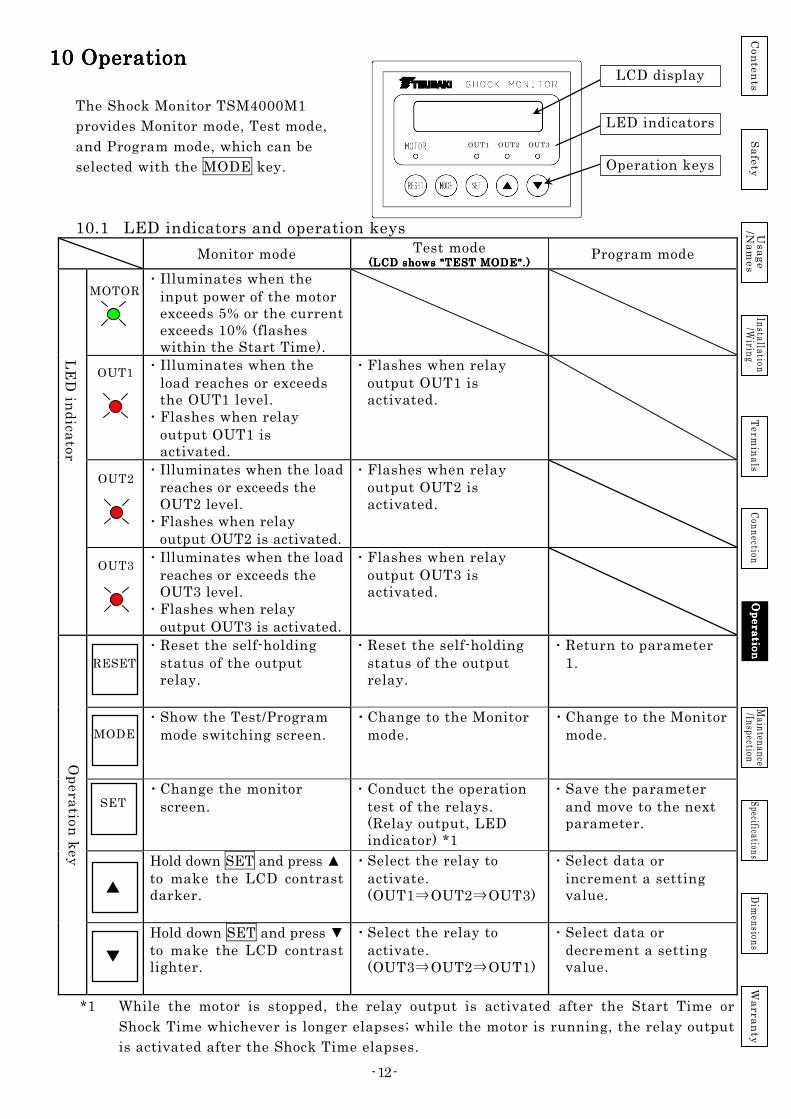
10 Operation10 Operation10 Operation10 Operation
The Shock Monitor TSM4000M1
provides Monitor mode, Test mode,
and Program mode, which can be
selected with the MODE key.
10.1 LED indicators and operation keys Monitor mode Test mode
(LCD shows "TEST MODE".)(LCD shows "TEST MODE".)(LCD shows "TEST MODE".)(LCD shows "TEST MODE".) Program mode
・ Illuminates when the input power of the motor exceeds 5% or the current exceeds 10% (flashes within the Start Time).
・ Illuminates when the load reaches or exceeds the OUT1 level.
・ Flashes when relay output OUT1 is activated.
・ Flashes when relay output OUT1 is activated.
・ Illuminates when the load reaches or exceeds the OUT2 level.
・ Flashes when relay output OUT2 is activated.
・ Flashes when relay output OUT2 is activated.
・ Illuminates when the load reaches or exceeds the OUT3 level.
・ Flashes when relay output OUT3 is activated.
・ Flashes when relay output OUT3 is activated.
・ Reset the self-holding status of the output relay.
・ Reset the self-holding status of the output relay.
・ Return to parameter 1.
・ Show the Test/Program mode switching screen.
・ Change to the Monitor mode.
・ Change to the Monitor mode.
・ Change the monitor screen.
・ Conduct the operation test of the relays. (Relay output, LED indicator) *1
・ Save the parameter and move to the next parameter.
Hold down SET and press to make the LCD contrast darker.
・ Select the relay to activate. (OUT1⇒OUT2⇒OUT3)
・ Select data or increment a setting value.
Hold down SET and press to make the LCD contrast lighter.
・ Select the relay to activate. (OUT3⇒OUT2⇒OUT1)
・ Select data or decrement a setting value.
*1 While the motor is stopped, the relay output is activated after the Start Time or
Shock Time whichever is longer elapses; while the motor is running, the relay output
is activated after the Shock Time elapses.
MOTOR
OUT2
OUT3
LE
D in
dica
tor
OUT1
RESET
SET
LCD display
LED indicators
Operation keys
Op
era
tion
ke
y
MODE
Co
nte
nts
U
sa
ge
/N
am
es
Sa
fety
In
stallation
/Wirin
g T
ermin
als
Con
nection
O
pe
ra
tion
Op
era
tion
Op
era
tion
Op
era
tion
M
ainten
ance
/Inspection
Specifications
Dim
ension
s W
arra
nty
OUT1 OUT2 OUT3

- 13 -
10.2 Switching modes When the Shock Monitor is turned on, the initial screen is displayed for about three
seconds, and then the device enters the Monitor mode.
The Monitor mode is used for load monitoring.
To change parameters,
press the MODE key to
go to the Program mode
selection screen. Press
the SET key to change
to the Program mode.
On the MODE selection
screen, press the MODE
key again to go to the
Test mode selection
screen.
Press the SET key here
to change to the Test
mode. In the Test mode,
you can activate the
output relay to issue
outputs.
Press the MODE key to
return to the Monitor
mode.
10.3 Monitor mode The Monitor mode is used to actually monitor the load. The LCD display shows the current
load ratio, current overload judgment criterion [No.], and the setting values for OUT1,
OUT2 and OUT3. The display can be shown separately for relative and absolute values,
which can be switched with the MODE key.
For power monitoring, the displayed load ratio is a value calculated on the
assumption that the selected motor capacity is 100%. The relative value display
shows the difference between reference value.
Co
nte
nts
U
sa
ge
/N
am
es
Sa
fety
In
stallation
/Wirin
g T
ermin
als
Con
nection
O
pe
ra
tion
Op
era
tion
Op
era
tion
Op
era
tion
M
ainten
ance
/Inspection
Specifications
Dim
ension
s W
arra
nty
PWi 5% [1]o1: 10 o2: 15
OUT2 setting level
0.43kW 2.80A 200V 60Hz
SET SET
TSM4000M1
POWER ON Ver *.**
Monitor mode (Relative value)
PWi 5%
[1]o1: 10 o2: 15
MODE
MODE Program mode
SET
0.43kW 2.80A 200V 60Hz
SET
PWa 58%
[1]o3: 80
Monitor mode (Absolute value)
TEST MODE
PROGRAM MODE
Test mode
1 : P a r a m e t e r L o c k
( 1 ) U n l o c k e d
Set>>>OUT3 Trip
UP>OUT1 Down>OUT3
SET
MODE
MODE
0.43kW 2.80A 200V 60Hz
SET
Turning on the operational power supply
Load ratio (relative value display)
PWi ・・・Relative value
PWa ・・・Absolute value
Detection level selection No. [1]
OUT1 setting level
Detected power, current,
voltage, and frequency

- 14 -
10.4 Test mode In the Test mode, you can check the operation of the output relays and LED
indicators. Since load monitoring is disabled in the Test mode, be sure to return to
the Monitor mode after the operation (or after pressing RESET when the relay output
is in the self-holding status).
10.5 Program mode The Program mode is used for changing and checking parameters.
Press the SET key to save data
and go to the next parameter.
Press the / key
to change data.
Press the RESET key to
return to "1:".
ON
MOTOR LED
Operation LED
Operating relay (Self-Hold) ON
Shock Time
Start Time
Operating relay (Auto-Reset) ON
Resets automatically 1 second.
Press the
RESET key.
Whichever is longer is applied.
PROGRAM MODE
SET
1:Parameter Lock
(1)Unlocked
1:Parameter Lock
(2)Locked
2:Motor Voltage
(1) 200-230V
Co
nte
nts
U
sa
ge
/N
am
es
Sa
fety
In
stallation
/Wirin
g T
ermin
als
Con
nection
O
pe
ra
tion
Op
era
tion
Op
era
tion
Op
era
tion
M
ainten
ance
/Inspection
Specifications
Dim
ension
s W
arra
nty
The OUT3 relay issues output,
and LED OUT3 illuminates.
The OUT2 relay issues output,
and LED OUT2 illuminates.
Hold down the key.
The OUT1 relay issues output,
and LED OUT1 illuminates.
SET
TEST MODE
Set>>>OUT3 Trip
UP>o1 Down>o2
TEST MODE
OUT3 OUT
SET
TEST MODE
OUT2 OUT
TEST MODE
OUT1 OUT
Set>>>OUT2 Trip
UP>o3 Down>o1 SET
Set>>>OUT1 Trip
UP>o2 Down>o3 SET
Hold down the key.
Hold down the key.

- 15 -
Parameter description and setting procedure
Parameter (Default data is shown.)
Data Description
(1)Unlocked ・ All parameters can be changed.
(2)Locked ・ Parameters other than the current parameter cannot be changed.
Motor voltage setting (1)200-230V ・ Select (1) to monitor a 200 V class motor. The allowable maximum voltage is 250 VAC.
(2)380-460V ・ Select (2) to monitor a 400 V class motor. The allowable maximum voltage is 500 VAC. Monitoring a 400 V class motor requires the installation of the optional 400 V class resistor.
Motor capacity setting (1)0.1kW (11)15kW Set the capacity of the motor to be monitored. The load ratio display of the Shock Monitor shows 100% when this motor capacity is detected. When a motor other than listed is used, select the nearest capacity.
(2)0.2kW (12)18.5kW
(3)0.4kW (13)22kW
(4)0.75kW (14)30kW
(5)1.5kW (15)37kW
(6)2.2kW (16)45kW
(7)3.7kW (17)55kW
(8)5.5kW (18)75kW
(9)7.5kW (19)90kW
(10)11kW (20)110kW
Start Time setting 0.1 to 20.0 s (Minimum setting increment: 0.1 s)
・ To prevent unnecessary operation during the startup period of the motor, the Shock Monitor disables the relay output function for a specified period after it is started, even in the Monitor mode.
・ Counting starts when the detected electric power reaches 5% or the current reaches 10% of the rated current.
・ Set the period as short as possible based on the startup time of the motor.
・ The Start Time starts when the Shock Monitor returns from the Test mode or Program mode to the Monitor mode.
2 :2 :2 :2 : M o t o r V o l t a g eM o t o r V o l t a g eM o t o r V o l t a g eM o t o r V o l t a g e
( 1 ) 2 0 0( 1 ) 2 0 0( 1 ) 2 0 0( 1 ) 2 0 0 ---- 2 3 0 V2 3 0 V2 3 0 V2 3 0 V
3 : M o t o r k W3 : M o t o r k W3 : M o t o r k W3 : M o t o r k W
( 4 ) 0 . 7 5 k W( 4 ) 0 . 7 5 k W( 4 ) 0 . 7 5 k W( 4 ) 0 . 7 5 k W
1 : P a r a m e t e r L o c k1 : P a r a m e t e r L o c k1 : P a r a m e t e r L o c k1 : P a r a m e t e r L o c k
( 1 ) U n l o c k e d( 1 ) U n l o c k e d( 1 ) U n l o c k e d( 1 ) U n l o c k e d
… S e l e c t d a t a .
SET…Make the set data effective.
4 : S t a r t T i m e4 : S t a r t T i m e4 : S t a r t T i m e4 : S t a r t T i m e
3 . 0 s3 . 0 s3 . 0 s3 . 0 s
… S e l e c t d a t a .
SET…Make the set data effective.
… S e l e c t d a t a .
SET…Make the set data effective.
SET…Make the set data effective.
…Increment the setting value.
…Decrement the setting value.
Co
nte
nts
U
sa
ge
/N
am
es
Sa
fety
In
stallation
/Wirin
g T
ermin
als
Con
nection
O
pe
ra
tion
Op
era
tion
Op
era
tion
Op
era
tion
M
ainten
ance
/Inspection
Specifications
Dim
ension
s W
arra
nty

- 16 -
Parameter (Default data is shown.) Data Description
No. of selected detection levels
1 to 8 There are up to eight possible combinations of the statuses of 6:OUT1 Level , 9:OUT2 Level , and 12:OUT3 Level . Select how many combinations to use.
Relative value upper limit 1 level setting
OUT1 1 to 99%
Set the OUT1 output level. Output is activated when the load ratio reaches or exceeds this setting value for the period specified at 7:Shock Time or longer.
Shock Time setting MIN (Shock Time:
Minimum)
[Time required for detection and output] ・ Motor power supply frequency: 50 Hz or more
・・・ Approx. 50 ms ・ Motor power supply frequency: Less than 50 Hz
・・・ 2 cycles + Approx. 10 ms (Example: 40 Hz・・・・・60 ms)
0.1 to 10.0 s (Minimum setting increment: 0.1 s)
・ Period between the instant when the load ratio reaches or exceeds the setting value and the instant when the relay output is activated.
・ If the load ratio goes below the value of
6:OUT1 Level within the specified period, the relay output is not activated.
Relay output mode setting (1)Self-Hold (Self holding)
The status of the relay output is retained. The status is reset by pressing the RESET key or by an input to the [RST] terminal.
(2)Auto-Reset (Automatic reset)
The status is reset one second after the relay output condition is cleared.
8:Output Relay O1 (2)Auto-Reset
5 : P r o c e s s5 : P r o c e s s5 : P r o c e s s5 : P r o c e s s
1111
When 2 is
selected
SET…Make the set data effective.
SET
SET
SET
SET
SET
5 : P r o c e s s 2
7:Shock Time O1 1.0s
6:OUT1 Level Process[1] 100%
SET
SET
7 : S h o c k T i m e7 : S h o c k T i m e7 : S h o c k T i m e7 : S h o c k T i m e
O U T 1O U T 1O U T 1O U T 1 1 . 01 . 01 . 01 . 0 ssss
… S e l e c t d a t a .
SET…Make the set data effective.
8 : O u t p u t R e l a y8 : O u t p u t R e l a y8 : O u t p u t R e l a y8 : O u t p u t R e l a y
O 1O 1O 1O 1 ( 2 ) A u t o( 2 ) A u t o( 2 ) A u t o( 2 ) A u t o ---- R e s e tR e s e tR e s e tR e s e t
SET…Make the set data effective.
6 :6 :6 :6 : O U T 1O U T 1O U T 1O U T 1 L e v e lL e v e lL e v e lL e v e l
P r o c e s s [ 1 ] 1 0 0 %P r o c e s s [ 1 ] 1 0 0 %P r o c e s s [ 1 ] 1 0 0 %P r o c e s s [ 1 ] 1 0 0 %
…Increment the setting value.
…Decrement the setting value.
…Increment the setting value.
…Decrement the setting value.
…Increment the setting value.
…Decrement the setting value.
6:OUT1 Level Process[2] 80%
9:OUT2 Level Process[1] 100%
9:OUT2 Level Process[2] 100%
10:Shock Time O2 1.0s
11:Output Relay O2 (1)Self-Hold
SET…Make the set data effective.
SET
Co
nte
nts
U
sa
ge
/N
am
es
Sa
fety
In
stallation
/Wirin
g T
ermin
als
Con
nection
O
pe
ra
tion
Op
era
tion
Op
era
tion
Op
era
tion
M
ainten
ance
/Inspection
Specifications
Dim
ension
s W
arra
nty
- 17 -
Parameter (Default data is shown.)
Data Description
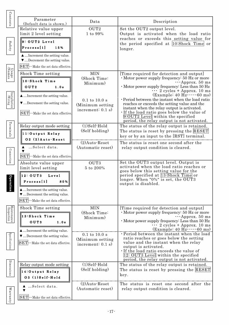
Relative value upper limit 2 level setting
OUT2 1 to 99%
Set the OUT2 output level. Output is activated when the load ratio reaches or exceeds this setting value for the period specified at 10:Shock Time or longer.
Shock Time setting MIN (Shock Time:
Minimum)
[Time required for detection and output] ・ Motor power supply frequency: 50 Hz or more
・・・Approx. 50 ms ・ Motor power supply frequency: Less than 50 Hz
・・・ 2 cycles + Approx. 10 ms (Example: 40 Hz・・・・・60 ms)
0.1 to 10.0 s (Minimum setting increment: 0.1 s)
・ Period between the instant when the load ratio reaches or exceeds the setting value and the instant when the relay output is activated.
・ If the load ratio goes below the value of 9:OUT2 Level within the specified period, the relay output is not activated.
Relay output mode setting (1)Self-Hold (Self holding)
The status of the relay output is retained. The status is reset by pressing the RESET key or by an input to the [RST] terminal.
(2)Auto-Reset (Automatic reset)
The status is reset one second after the relay output condition is cleared.
Absolute value upper limit level setting
OUT3 5 to 200%
Set the OUT3 output level. Output is activated when the load ratio reaches or goes below this setting value for the period specified at 13:Shock Time or longer. When "0%" is set, the OUT3 output is disabled.
Shock Time setting MIN (Shock Time:
Minimum)
[Time required for detection and output] ・ Motor power supply frequency: 50 Hz or more
・・・Approx. 50 ms ・ Motor power supply frequency: Less than 50 Hz
・・・ 2 cycles + Approx. 10 ms (Example: 40 Hz・・・・・60 ms)
0.1 to 10.0 s (Minimum setting increment: 0.1 s)
・ Period between the instant when the load ratio reaches or goes below the setting value and the instant when the relay output is activated.
・ If the load ratio exceeds the value of 12: OUT3 Level within the specified period, the relay output is not activated.
Relay output mode setting
(1)Self-Hold (Self holding)
The status of the relay output is retained. The status is reset by pressing the RESET key.
(2)Auto-Reset (Automatic reset)
The status is reset one second after the relay output condition is cleared.
9 :9 :9 :9 : O U T 2 L e v e lO U T 2 L e v e lO U T 2 L e v e lO U T 2 L e v e l
P r o c e s s [ 1 ] P r o c e s s [ 1 ] P r o c e s s [ 1 ] P r o c e s s [ 1 ] 1 51 51 51 5 %%%%
SET…Make the set data effective.
1 0 : S h o c k T i m e1 0 : S h o c k T i m e1 0 : S h o c k T i m e1 0 : S h o c k T i m e
O U T 2O U T 2O U T 2O U T 2 1 . 0 s1 . 0 s1 . 0 s1 . 0 s
SET…Make the set data effective.
…Increment the setting value.
…Decrement the setting value.
1 1 : O u t p u t R e l a y1 1 : O u t p u t R e l a y1 1 : O u t p u t R e l a y1 1 : O u t p u t R e l a y
O 2O 2O 2O 2 ( 2 ) A u t o( 2 ) A u t o( 2 ) A u t o( 2 ) A u t o ---- R e s e tR e s e tR e s e tR e s e t
SET…Make the set data effective.
1 2 :1 2 :1 2 :1 2 : O U T 3O U T 3O U T 3O U T 3 L e v e lL e v e lL e v e lL e v e l
P r o c e s s [ 1 ] P r o c e s s [ 1 ] P r o c e s s [ 1 ] P r o c e s s [ 1 ] 8 08 08 08 0 %%%%
1 3 : S h o c k T i m e1 3 : S h o c k T i m e1 3 : S h o c k T i m e1 3 : S h o c k T i m e
O U T 3O U T 3O U T 3O U T 3 1 . 0 s1 . 0 s1 . 0 s1 . 0 s
SET…Make the set data effective.
SET…Make the set data effective.
… S e l e c t d a t a .
1 4 : O u t p u t R e l a y1 4 : O u t p u t R e l a y1 4 : O u t p u t R e l a y1 4 : O u t p u t R e l a y
O 3O 3O 3O 3 ( 1 ) S e l f( 1 ) S e l f( 1 ) S e l f( 1 ) S e l f ---- H o l dH o l dH o l dH o l d
SET…Make the set data effective.
… S e l e c t d a t a .
Co
nte
nts
U
sa
ge
/N
am
es
Sa
fety
In
stallation
/Wirin
g T
ermin
als
Con
nection
O
pe
ra
tion
Op
era
tion
Op
era
tion
Op
era
tion
M
ainten
ance
/Inspection
Specifications
Dim
ension
s W
arra
nty
…Increment the setting value.
…Decrement the setting value.
…Increment the setting value.
…Decrement the setting value.
…Increment the setting value.
…Decrement the setting value.

- 18 -
Parameter (Default data is shown.) Data Description
Number of moving average sampling times
(1)QUICK (2)NORMAL (3)SLOW
Set the response time for electric power detection. The moving average of the sampling values obtained at every 20 ms (*) is calculated and treated as effective data. There are three options to set the number of sampling values used for the average calculation.
・ QUICK: Set this option when quick response is required. The data of one sampling value is regarded as effective data (20 ms).
・ NORMAL: Use this setting for normal operation. The average of five sampling values is regarded as effective data (100 ms).
・ SLOW: Set this option when you want to reduce display fluctuation. The average of 20 sampling values is regarded as effective data (400 ms).
*...The sampling cycle is fixed to 20 ms at 50 Hz or higher frequencies, and to one cycle at less than 50 Hz.
Motor power supply frequency: 50 Hz or more Detection time = 20 ms x (Setting value of Parameter 16) Motor power supply frequency: Less than 50 Hz Detection time = 1 cycle x (Setting value of Parameter 16)
IH ・ Load monitoring is disabled while the input signal IH is ON. The load ratio display shows flashing 0%.
・ When the input signal IH turns OFF and the load ratio has reached or exceeded the setting level for the Shock Time period or longer, the relay output is activated immediately.
0.1 to 10.0 s ・ When the input signal IH turns from OFF to ON, load monitoring is disabled within this specified time.
・ After the process switching signals X1, X2, and X3 are changed, load monitoring is disabled within this specified time.
・ When this specified time elapses and the load ratio has reached or exceeded the setting level for the Shock Time period or longer, the relay output is activated immediately.
(1)On When the Shock Monitor detects the change in the motor power supply frequency and the frequency continues changing at the rate of 4 Hz or higher per second, inhibit function is activated regardless of the inhibit time setting.
(2)Off The Auto Inhibit is disabled.
LCD backlight setting (1)Always The backlight illuminates all the time.
(2)2min The backlight will turn off two minutes after the last key operation on the panel. After the backlight turns off, it illuminates again when any key is pressed.
1111 5555 : R e s p o n s e: R e s p o n s e: R e s p o n s e: R e s p o n s e
( 2 ) N O R M A L( 2 ) N O R M A L( 2 ) N O R M A L( 2 ) N O R M A L
SET…Make the set data effective.
…Increment the setting value.
…Decrement the setting value.
SET…Make the set data effective.
1111 6666 : I: I: I: I n h i b i t T i m en h i b i t T i m en h i b i t T i m en h i b i t T i m e
I HI HI HI H
1111 7777 : A u t o I n h i b i t: A u t o I n h i b i t: A u t o I n h i b i t: A u t o I n h i b i t
( 2 ) O f f( 2 ) O f f( 2 ) O f f( 2 ) O f f
… S e l e c t d a t a .
… S e l e c t d a t a .
SET…Make the set data effective.
1 81 81 81 8 : L C D B a c k l i g h t: L C D B a c k l i g h t: L C D B a c k l i g h t: L C D B a c k l i g h t
( 1 ) A l w a y s( 1 ) A l w a y s( 1 ) A l w a y s( 1 ) A l w a y s
SET…Make the set data effective.
… S e l e c t d a t a .
Co
nte
nts
U
sa
ge
/N
am
es
Sa
fety
In
stallation
/Wirin
g T
ermin
als
Con
nection
O
pO
pO
pO
pe
ra
tion
era
tion
era
tion
era
tion
M
ainten
ance
/Inspection
Specifications
Dim
ension
s W
arra
nty

- 19 -
[Contact detection monitoring function]
1. When the reference load ratio is written, SET appears
at the upper right of the LCD display for one secondone secondone secondone second.
2. If the detection level reaches or exceeds 200% when the
reference load ratio is being written, "NG" is displayed
at the upper right of the LCD display.
3. You can write the reference load ratio manually by
pressing the and keys simultaneously while the
motor is running.
Example timing chart for the workpiece contact detection using the relative value monitoring
Emergency stop using the absolute value monitoring when a foreign material gets stuck
ON
ON
Shock Time for OUT1
OUT1 Setting level
RUN indicator
OUT1 indicator
OUT1 output relay ON
Start Time
OffsetOffsetOffsetOffset
Idle Contact with a workpiece
Used for a command to switch to lower delivery speed
ON
ON
OUT3 Setting level
RUN indicator
OUT3 indicator
OUT3 output relay
ON
When parameter 4
is set to Self-Hold
Shock Time for OUT3
Start Time
Used for emergency stop
Normal operation Foreign material gets stuck.
Ele
ctric po
we
r E
lectric p
ow
er
PW 58% SET
[1] o1: 10% o2: 15%
PW 58% NG
[1] o1: 10% o2: 15%
Co
nte
nts
U
sa
ge
/N
am
es
Sa
fety
In
stallation
/Wirin
g T
ermin
als
Con
nection
O
pe
ra
tion
Op
era
tion
Op
era
tion
Op
era
tion
M
ainten
ance
/Inspection
Specifications
Dim
ension
s W
arra
nty

- 20 -
11. Troubleshooting11. Troubleshooting11. Troubleshooting11. Troubleshooting
Problem Inspection item Inspection result Countermeasure
The LCD display shows nothing.
Wiring of the operational power supply (Between terminals 11 and 12)
No wiring installed. Install the wiring properly.
Operational power supply voltage (Between terminals 11 and 12)
Less than 90 VAC Provide voltage of 90 to 250 VAC.
90 to 250 VAC Replace or repair Shock Monitor.
The LCD display is illegible.
Adjust the contrast (Refer to page 9.).
The display becomes dark. Re-adjust the contrast.
The display does not improve.
Replace or repair Shock Monitor.
Output is activated immediately after Shock Monitor starts.
In the Program mode, check the setting value of 4:Start Time.
Short Set a little longer value.
Long (It is clear that the output is activated within the setting value.)
Replace or repair Shock Monitor.
Even when a long value is set to 4:Start Time (20 seconds max.), the relay is activated as soon as the time is up.
Startup time of the motor Acceleration time of the inverter
Longer than 20 seconds Review the motor capacity. Set a shorter acceleration time.
In the Monitor mode, check the load ratio and setting level at startup.
The setting value is small. Set a larger value in the Program mode.
Wrong detection level is selected.
Check the process switching input.
The load ratio is shown as 0%.
Is the current sensor and main unit connected?
The sensor cable is disconnected.
Connect the cable properly.
Does the V-phase motor wire pass through the current sensor?
・ No wire passes through the sensor.
・ Other phase
Install the wiring properly.
Check the wiring of the voltage input U, V, W (Terminals 1, 2, 3).
・ No wiring installed or wiring is disconnected.
・ Incorrect wiring
Install the wiring properly.
Although the motor starts, the displayed load ratio is wrong with respect to the actual load.
Model number of the current sensor
Wrong Replace with a correct sensor.
Does the V-phase motor wire pass through the current sensor?
Other phase (U-phase or W-phase)
Install the wiring properly.
Is the No. of times to pass the wire through the sensor correct?
Wrong
Check the wiring of the voltage input U, V, W (Terminals 1, 2, 3).
・ No wiring installed or wiring is disconnected.
・ Incorrect wiring
Install the wiring properly.
In the Monitor mode, check that the correct motor has been selected.
The selection does not correspond with the actual motor.
Set the parameters (2 and 3) properly.
Start the motor, change the display screen, and check the voltage and current values.
The load ratio far deviate from the displayed current value.
Repair Shock Monitor. Replace Shock Monitor.
The displayed load ratio is negative.
Is the motor operation status negative torque?
Rapid deceleration is caused by inverter operation.
If the actual torque is negative, the display is not abnormal.
The operation is affected by load.
If the actual torque is negative, the display is not abnormal.
Check the wiring of the voltage input U, V, W (Terminals 1, 2, 3).
・ No wiring installed or wiring is disconnected.
・ Incorrect wiring
Install the wiring properly.
Does the motor wire pass through the current sensor in the right direction? (Does the direction match with the arrow on the top of the current sensor?)
Opposite direction Install the wiring properly.
The load torque is positive and the motor wire correctly passes through the current sensor.
・ Replace Shock Monitor. ・ Repair Shock Monitor.
Although the load ratio display is correct, the relay output is not activated.
In the Monitor mode, check the multi-step selection and level setting values.
The process switching selection is incorrect. (X1, X2, X3)
Set the detection level selection input properly.
The level setting values are not set properly.
Set appropriate values.
In the Program mode, check the Shock Time.
Too long. Set a shorter value.
Co
nte
nts
U
sa
ge
/N
am
es
Sa
fety
In
stallation
/Wirin
g T
ermin
als
Con
nection
O
pe
ra
tion
M
ainten
ance
Main
tenan
ceM
ainten
ance
Main
tenan
ce/In
spection/In
spection/In
spection/In
spection
Specifications D
imen
sions
Wa
rra
nty

- 21 -
Problem Inspection item Inspection result Countermeasure
The LED indicator (OUT1, OUT2, OUT3) illuminates, but the relay output is not activated.
Is the load fluctuation too great?
The load fluctuates greatly and it instantaneously exceeds the setting level repeatedly.
Set the parameters (6, 9, 12, and 16) properly.
The load does not fluctuate and there is a great difference from the setting level.
Repair Shock Monitor.
The relay output is activated as soon as Shock Monitor is turned ON.
Is the motor starts when Shock Monitor is turned ON?
The displayed load is larger than the setting value.
Set the parameters (6 and 9) properly.
The output is activated even when the motor is stopped and the displayed load is 0. (Shock Monitor is used in a highly humid environment with corrosive gas.)
Repair Shock Monitor.
12. Trip 12. Trip 12. Trip 12. Trip ResetResetResetReset ProcedureProcedureProcedureProcedure (1) Inspect the equipment for any abnormalities. (2) If an abnormality is found, eliminate the cause and reset the equipment to normal status. (3) If the relay output is in self-holding status, press the RESET key to reset it. The
reset is also possible by turning off the operational power supply for the Shock Monitor for a short time.
(4) After confirming steps (1), (2), and (3), restart the equipment.
13. Precautions on Maintenance/Inspection13. Precautions on Maintenance/Inspection13. Precautions on Maintenance/Inspection13. Precautions on Maintenance/Inspection Be sure to observe the following during the maintenance/inspection work.
(1) To prevent secondary damage, clean up the surrounding area and ensure safety during the work.
(2) Before inspecting the installation or connection of the Shock Monitor, be sure to turn off the power to make the machine completely stop and the LCD display of the Shock Monitor completely turn off. Ensure that the Shock Monitor will not be turned on accidentally.
(3) Observe the guidelines listed in the Labor Safety and Health Regulation. (4) When conducting a megger test or dielectric withstanding voltage test, remove the Shock
Monitor main unit from the socket to avoid test voltage.
14. Periodic Inspection14. Periodic Inspection14. Periodic Inspection14. Periodic Inspection (1) Inspect that the "MOTOR RUN" LED indicator of the Shock Monitor illuminates while the
motor is running, and the load ratio value on the LCD display is normal. (Daily inspection) (2) In the Test mode, inspect the operation of the relay outputs OUT1, OUT2, and OUT3
on a regular basis. (3) Inspect for looseness in the installation of the Shock Monitor main unit and current
sensor on a regular basis. (4) Inspect for looseness in the terminal connection of the Shock Monitor main unit and
sensor cable connection on a regular basis. (5) Although the life of the Shock Monitor varies depending on the installation
environment and operating time, the life of the electrolytic capacitor is normally about 10 years under continuous energization at annual average ambient temperature of 30°C. It is recommended to overhaul the Shock Monitor or replace it with a new one before any problem occurs.
(6) The brightness of the LCD display varies depending on the ambient temperature and operating time. If the display becomes illegible, adjust the contrast.
Perform the periodic inspection during trial operation, and when the equipment was moved, and when the wiring was changed.
15. For Your Safety15. For Your Safety15. For Your Safety15. For Your Safety (1) If any danger is expected as a result of the operation of Shock Monitor, be sure to
take measures to avoid such danger. (2) Also, give due consideration on the equipment side so that, even if Shock Monitor
does not operate normally, no dangerous situation would develop.
!!!!
!!!!
Co
nte
nts
U
sa
ge
/N
am
es
Sa
fety
In
stallation
/Wirin
g T
ermin
als
Con
nection
O
pe
ra
tion
M
ainten
ance
Main
tenan
ceM
ainten
ance
Main
tenan
ce/In
spection/In
spection/In
spection/In
spection
Specifications D
imen
sions
Wa
rra
nty

- 22 -
16161616. Specifications. Specifications. Specifications. Specifications
Model number TSM4000M1 TSM4000 M1P
Applicable motor
Capacity 0.1 to 110 kW Voltage 3-phase, 200/220 VAC or 400/440 VAC
Power supply frequency 5 to 120 Hz
Operational power supply voltage Commercial power supply 90 to 250 VAC 50/60 Hz,
90 to 250 VDC No polarity
Inpu
t
Terminals 17, 18, 19 250 VAC max. *1
Current sensor 2.5 VDC
Se
tting
Power setting range
Relative value upper limit 1 (OUT1)
1 to 99%
Relative value upper limit 2 (OUT2)
1 to 99%
Absolute value upper limit (OUT3)
5 to 200%
Start Time setting range 0.1 to 20.0 s
Shock Time setting range MIN or 0.1 to 10.0 s
When the motor power supply frequency is 50 Hz or more, the Shock Time for "MIN" is approximately 30 ms. *2
No. of processes 1 to 8 Response QUICK, NORMAL, SLOW
Disp
lay
Power percentage display range 0 to +200%
Voltage display range 0 to 500 V (Resolution: 1% of motor rated voltage)
Current display range 0.01 to 999 A (Resolution: 1% of motor rated current)
Frequency display range 5 to 120 Hz
Ou
tpu
t
Relay contact output (OUT1 - OUT3)
250 VAC, 0.5A (Inductive load cosφ = 0.4) 30 VDC, 0.4 A (Inductive load) 110 VDC, 0.2A (Inductive load)
24 VDC, 4 mA 100,000 times of operation
Analog output signal 0 to 10 VDC
Oth
er
Inhibit function
When the frequency changes by 4 Hz/s or more, the electric power detection is stopped.
When the section between X4 and CM is short-circuited, electric power detection is stopped
for a period between 0.1 and 10.0 s or while the section is short-circuited.
Test function Operation check of relays OUT1 - OUT3 in Test mode
Peak-hold function Maximum power value during Shock Time period is
displayed. (Disabled when Auto-Reset is set)
Power consumption 10 VA (Inrush current 5A within 5 ms) Approximate weight 1.0 kg
Operating environment
Ambient temperature 0 to +50
Relative humidity 45 to 85% RH, no condensation Altitude 1,000 m max.
Atmosphere No oil mist, corrosive gases, and dust
Mounting DIN rail, screw mounting Panel mounting
Note) *1. To use a 400/440 VAC motor, the optional 400 V class resistor "TSM-PR1" is required.
*2. When the motor power supply frequency is less than 50 Hz, the Shock Time for "MIN" is 2 cycles of the power supply frequency + Approx. 10 ms. (Example for the case of 50 Hz: 40 + 10 = 50 ms)
Co
nte
nts
U
sa
ge
/N
am
es
Sa
fety
In
stallation
/Wirin
g T
ermin
als
Con
nection
O
pe
ra
tion
M
ainten
ance
/Inspection
SpecificationsSpecificationsSpecificationsSpecifications
Dim
ension
s W
arra
nty

- 23 -
17. Outer Dimensions17. Outer Dimensions17. Outer Dimensions17. Outer Dimensions Main unit TSM4000M1 TSM4000M1P
Current sensor TSM-U010, TSM-U050, TSM-U100 TSM-M300, TSM-M400, TSM-M600 TSM-U150, TSM-U200 TSM-M800
400 V class resistor Panel mounting bracket (for TSM4000M1P) TSM4-PR1 TSM4-PL1
Co
nte
nts
U
sa
ge
/N
am
es
Sa
fety
In
stallation
/Wirin
g T
ermin
als
Con
nection
O
pe
ra
tion
M
ainten
ance
/Inspection
Specifications
Dim
ension
sD
imen
sions
Dim
ension
sD
imen
sions
Wa
rra
nty
37
46
1 4 45
54
5
63
.5 ø20
8
C u r r e n t d i r e c t i o n m a r k Mounting hole: 2 - ø4
20
5
Mounting hole: ø4.6
C u r r e n t d i r e c t i o n m a r k
Mounting hole: R2.3
24
1 4
40 78
90
20
64
2
8
7
Mounti ng ho le d imension
Panel cuto ut d ime nsion
6-M4 s cre ws 2-M4 nuts
Rub ber sheets

- 24 -
Sensor cable I/O cable
TSM4-S01, TSM4-S03, TSM4-S05 TSM4-C01 TSM4-S10, TSM4-S20, TSM4-S30 TSM4-C03
18. Warranty18. Warranty18. Warranty18. Warranty
18.1 Free warranty period TEM shall offer free warranty period of 18 months after the shipment from the factory or 12 months after the beginning of the use (counted from the completion of the installation of the TEM product into your equipment), whichever is shorter.
18.2 Warranty coverage
Any failure or malfunction occurred in the TEM product within the free warranty period shall be repaired or be handled by replacing the failed part with no charge through the return of the product to TEM, as long as the proper installation, usage, and maintenance in accordance with the instruction manual are provided by the customer. Note, however, that this free warranty shall cover only the TEM product delivered to the customer and the following expenses shall not be covered by the warranty.
(1) The cost for the removal or installation of the TEM product from or to the customer's equipment for the purpose of replacement or repair, and the cost associated with such work.
(2) The transportation cost for sending the customer's equipment to the customer's repair plant or other place.
(3) The lost earnings of the customer resulted from the failure and/or repair, as well as other increased damages.
18.3 Paid warranty
Even within the free warranty period, if a failure or malfunction occurs in the TEM product due to any of the following causes, the investigation/repair shall be charged.
(1) The customer did not install the TEM product properly in accordance with the instruction manual.
(2) The customer did not handle the product properly and/or did not provide sufficient maintenance.
(3) The failure or malfunction was resulted from improper connection between the TEM product and other equipment.
(4) The customer changed the structure of the TEM product such as modification. (5) The TEM product was not repaired at TEM or TEM-designated plants. (6) The TEM product was not used in the appropriate operating environment described
in the instruction manual. (7) The failure or malfunction was caused by force majeure such as disasters or by
illegal behavior of a third party. (8) The failure of the TEM product was caused incidentally by the malfunction of the
customer's equipment. (9) The failure was caused by the installed customer-supplied part or by the part used
in accordance with the designation of the customer. (10) The failure was caused by failed wiring or incorrect parameter setting conducted by
the customer. (11) The product has reached its life which is normal for the operating condition. (12) Damage occurred due to the cause for which TEM was not liable.
Co
nte
nts
U
sa
ge
/N
am
es
Sa
fety
In
stallation
/Wirin
g T
ermin
als
Con
nection
O
pe
ra
tion
M
ainten
ance
/Inspection
Specifications
Dim
ension
s W
arr
an
tyW
arr
an
tyW
arr
an
tyW
arr
an
ty

MEMOMEMOMEMOMEMO

MEMOMEMOMEMOMEMO

TSUBAKIMOTO CHAIN CO. 1-1, Kohtari-Kuresumi, Nagaokakyo
Kyoto 617Kyoto 617Kyoto 617Kyoto 617---- 0833, Japan0833, Japan0833, Japan0833, Japan
Internet : http://tsubakimoto.com/
Tsubakimoto Singapore Pte. Ltd.
http://tsubaki.sg/
U.S. Tsubaki Power Transmission, LLC
http://www.ustsubaki.com/
Taiwan Tsubakimoto Co.
http://tsubakimoto.com.tw/
Tsubaki of Canada Limited
http://tsubaki.ca/
Tsubakimoto Chain (Shanghai) Co., Ltd.
http://tsubaki.cn/
Tsubaki Australia Pty. Limited
http://tsubaki.com.au/
Tsubakimoto Europe B.V.
http://tsubaki.eu/
Tsubakimoto U.K. Ltd.
http://tsubaki.eu/
Tsubakimoto Korea Co., Ltd.
http://tsubakimoto-tck.co.kr/