shop manual - sakai america shop manual provides instructions, for the most part, on general...
TRANSCRIPT

SHOP MANUAL
Series


PREFACE
To make a machine working to maximum efficiency over a long period of timewithout any machine troubles, correct OPERATION, PREVENTIVE MAINTE-NANCE, TROUBLE-SHOOTING and REPAIR are of vital importance.
This shop manual provides instructions, for the most part, on GENERALINFORMATION, STRUCTURE/FUNCTION, CHECKING/ADJUSTMENT, andTROUBLE-SHOOTING of the SAKAI SW300 Series Vibrating Rollers.
This manual is designed to serve as a guide for the operator and maintenancepersonnel to acquire correct information and repair procedure on thesemachines in order to give a correct decision on problems which the machineswill confront, thus leading to quality repair. Fully understand the contents of themanual and make the best of it.
We will make utmost efforts to make this manual more useful for you throughrevisions.Your opinions and advices wil l be particularly welcome and wil l becarefully considered.

CONTENTS■ SPECIFICATIONS ・・・・・・・・・・・・・・・・・・・・・・・・・・・・・・・・・・・・・・・・・1-001
■ STRUCTURE & OPERATION ・・・・・・・・・・・・・・・・・・・・・・・・・・・・・2-001
■ INSPECTION & ADJUSTMENT ・・・・・・・・・・・・・・・・・・・・・・・・・・・3-001
■ TROUBLE-SHOOTING ・・・・・・・・・・・・・・・・・・・・・・・・・・・・・・・・・・・・4-001


SPECIFICATIONS


1-001
SPECIFICATIONS1. External Views and Specifications■ 1-1. SW300・・・・・・・・・・・・・・・・・・・・・・・・・・・・・・・・・・・・・・・・・・・・・・・・・・・1-002■ 1-2. SW320・・・・・・・・・・・・・・・・・・・・・・・・・・・・・・・・・・・・・・・・・・・・・・・・・・・1-003■ 1-3. SW330・・・・・・・・・・・・・・・・・・・・・・・・・・・・・・・・・・・・・・・・・・・・・・・・・・・1-004

1-002
1130(44")
1750(69")
1000 (39")
¯700(27.5")
250
1950 (77")
2650 (104")
1000 (39")
SW3001001
(10")
Unit in mm {in}
SPECIFICATIONS
1. External Views and Specifications1-1. SW300
Model SW300 Vibrating power:Weight: Frequency 66.7 Hz {4,000 vpm}
Gross weight 2,700 kg {5,955 lbs}Centrifugal force
27.5 kN(6,175 lbs){2,800 kgf}Empty weight 2,525 kg {5,570 lbs}
Fuel tank
Dimension: Engine:Overall length 2,650 mm {104"} Model KUBOTA “D1703” Diesel EngineOverall width 1,130 mm {44"} Total displacement 1,647 cc {100.5 cu.in}Overall height 1,750 mm {69"}
Rated output25.4 kW/2,800 rpm(34.5 PS/2,800 rpm){34.0 HP/2,800 rpm}
Wheelbase 1,950 mm {77"}Wheel
FrontRoll (width x dia.)
1,000 x 700 mm {39" x 28"} Max. torque108 N•m/1,600 rpm
(11.0 kgf•m/1,600 rpm){79.6 lbf•ft/1,600 rpm}
RearRoll (width x dia.)
1,000 x 700 mm {39" x 28"}
Performance: 50 liters {13.2 gal}
Travel speed(forward/reverse)
0 ~ 12 km/h {0 ~ 7.5mile/h}Hydraulic tank 42 liters {11.1 gal}Sprinkler tank 180 liters {48 gal}
NOTE: Gradability is the calculated value. It may vary with ground surface conditions.
Gradability 24 degreesRolling width 1,000 mm {39"}
Minimum turningradius
3.7 m {146"}
Tank capacity:

SPECIFICATIONS
1-003
1-2. SW320
SW3001002
1330(52")
1750(69")
1200 (47")
¯700
(27.5")
250
1950 (77")
2650 (104")
1200 (47")
(10")
Unit in mm {in}
Model SW320 Vibrating power:Weight: Frequency 66.7 Hz {4,000 vpm}
Gross weight 2,865 kg {6,315 lbs}Centrifugal force
31.4 kN(7,055 lbs){3,200 kgf}Empty weight 2,960 kg {5,930 lbs}
Fuel tank
Dimension: Engine:Overall length 2,650 mm {104"} Model KUBOTA “D1703” Diesel EngineOverall width 1,330 mm {52"} Total displacement 1,647 cc {100.5 cu.in}Overall height 1,750 mm {69"}
Rated output25.4 kW/2,800 rpm(34.5 PS/2,800 rpm){34.0 HP/2,800 rpm}
Wheelbase 1,950 mm {77"}Wheel
FrontRoll (width x dia.)
1,200 x 700 mm {47" x 28"} Max. torque108 N•m/1,600 rpm
(11.0 kgf•m/1,600 rpm){79.6 lbf•ft/1,600 rpm}
RearRoll (width x dia.)
1,200 x 700 mm {47" x 28"}
Performance: 50 liters {13.2 gal}
Travel speed(forward/reverse)
0 ~ 12 km/h {0 ~ 7.5 mile/h}Hydraulic tank 42 liters {11.1 gal}Sprinkler tank 180 liters {48 gal}
NOTE: Gradability is the calculated value. It may vary with ground surface conditions.
Gradability 22 degreesRolling width 1,200 mm {47"}
Minimum turningradius
3.8 m {150"}
Tank capacity:
SPECIFICATIONS
1-004
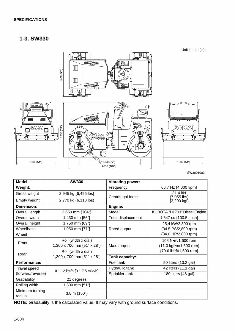
1-3. SW330
SW3001003
1430(56")
1750(69")
1300 (51")
¯700(27.5")
250
1950 (77")
2650 (104")
1300 (51")
(10")
Unit in mm {in}
Model SW330 Vibrating power:Weight: Frequency 66.7 Hz {4,000 vpm}
Gross weight 2,945 kg {6,495 lbs}Centrifugal force
31.4 kN(7,055 lbs){3,200 kgf}Empty weight 2,770 kg {6,110 lbs}
Fuel tank
Dimension: Engine:Overall length 2,650 mm {104"} Model KUBOTA “D1703” Diesel EngineOverall width 1,430 mm {56"} Total displacement 1,647 cc {100.5 cu.in}Overall height 1,750 mm {69"}
Rated output25.4 kW/2,800 rpm(34.5 PS/2,800 rpm){34.0 HP/2,800 rpm}
Wheelbase 1,950 mm {77"}Wheel
FrontRoll (width x dia.)
1,300 x 700 mm {51" x 28"} Max. torque108 N•m/1,600 rpm
(11.0 kgf•m/1,600 rpm){79.6 lbf•ft/1,600 rpm}
RearRoll (width x dia.)
1,300 x 700 mm {51" x 28"}
Performance: 50 liters {13.2 gal}
Travel speed(forward/reverse)
0 ~ 12 km/h {0 ~ 7.5 mile/h}Hydraulic tank 42 liters {11.1 gal}Sprinkler tank 180 liters {48 gal}
NOTE: Gradability is the calculated value. It may vary with ground surface conditions.
Gradability 21 degreesRolling width 1,300 mm {51"}
Minimum turningradius
3.8 m {150"}
Tank capacity:

STRUCTURE & OPERATION

2-001
STRUCTURE & OPERATION1. Location of Engine-related Key Units■ 1-1. Engine mount ・・・・・・・・・・・・・・・・・・・・・・・・・・・・・・・・・・・・・・・・・・・・・・・2-003■ 1-2. Intake system ・・・・・・・・・・・・・・・・・・・・・・・・・・・・・・・・・・・・・・・・・・・・・・・2-004■ 1-3. Exhaust system ・・・・・・・・・・・・・・・・・・・・・・・・・・・・・・・・・・・・・・・・・・・・・・2-005■ 1-4. Cooling piping & radiator ・・・・・・・・・・・・・・・・・・・・・・・・・・・・・・・・・・・・・・2-006■ 1-5. Fuel piping & fuel tank ・・・・・・・・・・・・・・・・・・・・・・・・・・・・・・・・・・・・・・・・2-007■ 1-6. Fuel controls ・・・・・・・・・・・・・・・・・・・・・・・・・・・・・・・・・・・・・・・・・・・・・・・・2-008
2. Description and Operation of Hydraulic System2-1. Description and operation of hydraulic pump and motor■ 2-1-1. Propulsion pump ass'y ・・・・・・・・・・・・・・・・・・・・・・・・・・・・・・・・・・・・・・2-009■ 2-1-2. Propulsion motor ・・・・・・・・・・・・・・・・・・・・・・・・・・・・・・・・・・・・・・・・・・・2-010■ 2-1-3. Description and operation of cam motor ・・・・・・・・・・・・・・・・・・・・・・・2-011■ 2-1-4. Vibrator pump ・・・・・・・・・・・・・・・・・・・・・・・・・・・・・・・・・・・・・・・・・・・・・2-013■ 2-1-5. Vibrator motor・・・・・・・・・・・・・・・・・・・・・・・・・・・・・・・・・・・・・・・・・・・・・・2-014■ 2-1-6. Description and operation of vibrator motor・・・・・・・・・・・・・・・・・・・・・2-015■ 2-1-7. Steering pump ・・・・・・・・・・・・・・・・・・・・・・・・・・・・・・・・・・・・・・・・・・・・・2-016■ 2-1-8. Hydraulic circuit ・・・・・・・・・・・・・・・・・・・・・・・・・・・・・・・・・・・・・・・・・・・・2-017
2-2. Propulsion line ■ 2-2-1. Hydraulic piping [1] ・・・・・・・・・・・・・・・・・・・・・・・・・・・・・・・・・・・・・・・・・2-019■ 2-2-2. Hydraulic piping [2] ・・・・・・・・・・・・・・・・・・・・・・・・・・・・・・・・・・・・・・・・・2-020■ 2-2-3. Propulsion controls ・・・・・・・・・・・・・・・・・・・・・・・・・・・・・・・・・・・・・・・・・2-021■ 2-2-4. Propulsion circuit ・・・・・・・・・・・・・・・・・・・・・・・・・・・・・・・・・・・・・・・・・・・2-022■ 2-2-5. Description and operation of propulsion system・・・・・・・・・・・・・・・・・2-023
2-3. Vibrating system■ 2-3-1. Hydraulic piping [1] ・・・・・・・・・・・・・・・・・・・・・・・・・・・・・・・・・・・・・・・・・2-024■ 2-3-2. Hydraulic piping [2] ・・・・・・・・・・・・・・・・・・・・・・・・・・・・・・・・・・・・・・・・・2-025■ 2-3-3. Vibrating system (SW300) ・・・・・・・・・・・・・・・・・・・・・・・・・・・・・・・・・・・2-026■ 2-3-4. Vibrating system (SW320, SW330)・・・・・・・・・・・・・・・・・・・・・・・・・・・・2-027■ 2-3-5. Vibrator circuit・・・・・・・・・・・・・・・・・・・・・・・・・・・・・・・・・・・・・・・・・・・・・・2-028■ 2-3-6. Description and operation of vibrating system ・・・・・・・・・・・・・・・・・・2-029
2-4. Steering system■ 2-4-1. Hydraulic piping ・・・・・・・・・・・・・・・・・・・・・・・・・・・・・・・・・・・・・・・・・・・・2-030■ 2-4-2. King pin ・・・・・・・・・・・・・・・・・・・・・・・・・・・・・・・・・・・・・・・・・・・・・・・・・・・2-031■ 2-4-3. Steering valve (Orbitrol) ・・・・・・・・・・・・・・・・・・・・・・・・・・・・・・・・・・・・・2-032■ 2-4-4. Description and operation of Orbitrol ・・・・・・・・・・・・・・・・・・・・・・・・・・2-033■ 2-4-5. Steering cylinder ass'y ・・・・・・・・・・・・・・・・・・・・・・・・・・・・・・・・・・・・・・2-037■ 2-4-6. Steering circuit ・・・・・・・・・・・・・・・・・・・・・・・・・・・・・・・・・・・・・・・・・・・・・2-038
2-002
3. Brake System■ 3-1. Brake pedal ・・・・・・・・・・・・・・・・・・・・・・・・・・・・・・・・・・・・・・・・・・・・・・・・・2-039■ 3-2. Description and operation of brake circuit ・・・・・・・・・・・・・・・・・・・・・・・2-040
4. Sprinkler & Scraper■ 4-1. Sprinkler piping ・・・・・・・・・・・・・・・・・・・・・・・・・・・・・・・・・・・・・・・・・・・・・・2-041■ 4-2. Scraper ・・・・・・・・・・・・・・・・・・・・・・・・・・・・・・・・・・・・・・・・・・・・・・・・・・・・・2-042
5.Electric System■ 5-1. Location of instrument panel and relays ・・・・・・・・・・・・・・・・・・・・・・・・・2-043■ 5-2. Location of electric components・・・・・・・・・・・・・・・・・・・・・・・・・・・・・・・・2-044■ 5-3. Electric wiring diagram・・・・・・・・・・・・・・・・・・・・・・・・・・・・・・・・・・・・・・・・2-045

Engine-related Units
2-003
SW3002001
2
2
2
1
11
1.Location of Engine-related Key Units1-1. Engine mount
1. Engine mount (front) 2. Engine mount (rear)

Engine-related Units
2-004
1. Duct hose2. Air cleaner 3. Intake hose
1-2. Intake system
SW3002002
2
3
1
3
2
3

2-005
Engine-related Units
1-3. Exhaust system
SW3002003
1
2
3
1
A
2
3
VIEW A
1. Exhaust pipe 2. Muffler 3. Exhaust pipe

1-4. Cooling piping & radiator
SW3002004
5
4
1
3
2
8
6
7
76
2
Engine-related Units
2-006
1. Reservoir2. Radiator3. Oil cooler4. Radiator inlet hose
5. Radiator outlet hose6. Drain hose (radiator)7. Drain hose (cylinder block) 8. Drain cock

2-007
Engine-related Units
1-5. Fuel piping & fuel tank
SW3002005
2
3
1
5
4
6
1. Suction hose 2. Filter 3. Fuel pump 4. Return hose 5. Fuel gauge unit 6. Fuel tank

2-008
Engine-related Units
1-6. Fuel controls
SW3002006
1
43
1
2
A B
VIEW BDETAIL A
1. Throttle lever 2. Control cable 3. Control lever (fuel injection pump) 4. Operating force adjusting nut

Description and Operation of Hydraulic System
2-009
SW3002007
7
6
6
7
9
2
81 5
4
10
3
2. Description and Operation of Hydraulic System2-1. Description and operation of hydraulic pump and motor
2-1-1. Propulsion pump ass'y
1. Port A (forward travel)2. Port B (reversing)3. High pressure relief valve (forward travel)4. High pressure relief valve (reversing)5. Charge relief valve6. Control lever7. Brake release solenoid valve8. Circuit pressure gauge port (forward travel)9. Circuit pressure gauge port (reversing)
10. Charge pressure gauge port
Specifications• Model : DVN28-504• Displacement : 28cm3/rev• Relief valve setting: 34.5MPa (5000psi) {350kgf/cm2}
• Charge circuit pressure setting: 1.9MPa (280psi) {20kgf/cm2}

2-010
Description and Operation of Hydraulic System
2-1-2. Propulsion motor
SW3002008
2 4
1
3
5 6 987 10 11 12 13
14
15
17
16241819202122
23
1. Port A 2. Port B 3. Drain port 4. Brake release pressure
gauge port 5. Large flange 6. Piston ring 7. Journal bearing 8. Cam ring
9. Roller10. Piston11. Cylinder block12. Distributor13. Brake shaft14. Brake spring 15. Brake cover16. Brake piston17. Friction plate
18. Separate plate19. Roller bearing 20. Oil seal21. Roller bearing 22. Dust seal23. Output shaft 24.Brake housing
Specifications• Model : DCM0280-517• Displacement : 417cm3/rev• Circuit pressure setting : 34.5MPa (5000psi) {350kgf/cm2 }To be set on propulsion pump side

Description and Operation of Hydraulic System
2-011
2-1-3. Description and operation of cam motor
Construction of cam motor• Made up of brake cover (15), brake housing (24), cam ring (8), large flange (5), cylinder block (11),
distributor (12) and output shaft (23).• Eight sets of pistons (10) are assembled into cylinder block (11), while brake housing (24) houses
spring-applied hydraulically released brake.• Brake cover (15), brake housing (24), cam ring (8) and large flange (5) form one body fixed with
fixing bolts.• Cylinder block (11) is spline fitted to output shaft (23) and rotates when under hydraulic pressure.
Cylinder block (11) has twelve oil holes to align with the holes in distributor (12).• Distributor (12) fitted to large flange (5) with dowel pin feeds oil, which is supplied from port A or
port B in large flange (5), to cylinder block (11) and also displaces oil from cylinder block (11). Forthis purpose, there are twelve oil holes in distributor (12). Six holes lead to port B in large flange (5)and other six holes to port A respectively. (See page 2-012)
• Inside surface of cam ring (8) are six cam profiles (see Fig.SW3002011 on page 2-012) alongwhich the pistons move to provide rotary motion.
• Cylinder block (11) is located with eight sets of pistons inside cam ring (8).
SW3002009�
23
58 10 1211
15
24

2-012
Description and Operation of Hydraulic System
SW3002011
Ports in distributor (twelve holes)
Piston (8 sets)10
Roller9
Cam ring (fixed)(Inner surface has six come profiles.)
8
Cylinder block(rotates)
11
Cylinder block ports(8 ports)
Fp
Fs Fn
Fp : Hydraulic forceFn : Vertical reaction from
cam ringFs : Rotary force
23
SW3002012
Port B
Port A
Operation (It is assumed that oil is fedinto port B.)• Pump flow to port B in large flange (5) is dis-
tributed into six holes in distributor (12)which lead to port B.* Oil is displaced from the remaining six
holes.• When the six holes in cylinder block (11)
align with the six holes in distributor (12),pressurized oil lifts pistons (10).
• Movement of pistons (10) which move alongthe cam profiles with rollers (9) in contactwith the profiles creates rotary force in cylin-der block (11). This force rotates outputshaft (23) spline fitted to cylinder block (11).
• Simultaneously, pistons (10) which are lead-ing to port A (discharge port) also movealong the cam formation to retract, displac-ing oil from port A.* If pump flow is fed into port A, the output
shaft rotation is reversed.
: High main pressure
: Low main pressure
Distributor(fixed)
SW3002010
12
To port ATo port B
High and low main pressures arealternately distributed to twelveholes in distributor (6).

2-013
Description and Operation of Hydraulic System
2-1-4. Vibrator pump
SW3002013
9 8 10 7 9
13
321
6 12 5
4
11
1. Outlet port (Pump No.1)2. Outlet port (Pump No.2)3. Suction port4. Drive gear (pump No.1)5. Oil seal
6. Drive gear (pump No.2)7. Driven gear (pump No.1)8. Driven gear (pump No.2)9. Bush
10. Bush
11. Front cover12. Body13. Rear cover
Specifications• Model : DIA14•14R270• Displacement : 13.7+13.7cm3/rev• Pressure setting : 12.7MPa (1840psi) {130kgf/cm2}To be set by valve

Description and Operation of Hydraulic System
2-014
2-1-5. Vibrator motor
SW3002014
SECTION A-A
14 11 12 10
4
5
2
1 3
76 8
A
A
9 13
15
1. Suction port (port A)2. Outlet port (port B)3. Drain port4. Drive shaft5. Oil seal
6. Ball bearing7. Timing ring8. Timing pin9. Cylinder block
10. Piston
11. Piston ring 12. Piston retainer13. Ball bearing14. Casing15. Pintle
Specifications• Model : SHM1• Displacement : 9cm3/rev• Pressure setting : 12.7MPa (1840psi) {130kgf/cm2}To be set by valve

2-015
Description and Operation of Hydraulic System
2-1-6. Description and operation of vibrator motor
* See figures on page 2-014 for construction.
• Pressurized oil fed from a port provided atrear of pintle (15) flows through the low-highpressure selecting section and radiated oilways of cylinder block (9) into one end of thepistons.
* In the center drawing, oil is occupyingspaces shown black in pistons 10-1, 10-2and 10-3.
• Point O is the rotating center of drive shaft(4), and point P shows the center of pintle(15). The center line of all pistons point topoint P. Resultant forces F1, F2 and F3 gen-erated by pistons 10-1, 10-2 and 10-3(center and bottom drawings) act on point Pand create a torque due to eccentric E.Because pintle (15) is fixed, drive shaft (4)which has a pentagon-shaped inner surfacespins.
• Drive shaft (4) and cylinder block (9) rotatewith their respective pentagon remainingparallel with each other because of timingpins (8) provided in cylinder block (9) andtiming ring (7) in drive shaft (4).
• The low-high pressure selecting section ofpintle (15) is made up of two flat faces of theeccentric cylinder and radiated portion (fiveholes into which the pistons are inserted) ofcylinder block (9). One of the two flat facesof the eccentric cylinder leads to high pres-sure inlet port, while the other face corre-sponds to the low pressure outlet port. Withthe rotation of cylinder block (9) which spinstogether with drive shaft (4), pressurized oilis fed into the pistons when the radiated por-tion of cylinder block (9) leads to the highpressure side of eccentric cylinder. On theother hand, oil is exhausted from the pistonsif the radiated portion is open to the lowpressure side.In this way, torque is created continuouslythrough flow in and flow out processes of oil.The motor runs continuously.
SW3002015
7 8 9
10
15
SW3002016
87
O�
P
4
10-5
910-1
10-2
10-3
SW3002017
E
O
F3
F123F2
F12
F1
P
(C) Moment created by hydraulic pressure

2-016
Description and Operation of Hydraulic System
2-1-7. Steering pump
SW3020187
6
5
3
5
5
9
52
8
1
4
1. Outlet port2. Suction port3. Drive gear
4. Driven gear5. Bush6. Oil seal
7. Ring8. Body9. Rear cover
Specifications• Displacement : 8.85cm3/rev• Pressure setting : 13MPa (1890psi) {133kgf/cm2}To be set on Orbitrol side

2-017
Description and Operation of Hydraulic System
2-1-8. Hydraulic circuit

2-018

2-019
Description and Operation of Hydraulic System
2-2. Propulsion line2-2-1. Hydraulic piping [1]
SW3002020
13 79
85
3 1
10
8
A
A
B
B
11
75
3
2
4
8
6
4
8
5
12
VIEW A-AVIEW B-B
1. Propulsion pump2. High pressure hose (front, forward travel)3. High pressure hose (front, reversing)4. High pressure hose (rear, forward travel)5. High pressure hose (rear, reversing)6. Charge hose7. Brake release hose (front)
8. Brake release hose (rear)9. Drain hose (pump to oil cooler)
10. Drain hose (pump to hydraulic tank)11. Oil cooler12. Drain hose (rear motor to hydraulic tank)13. Drain hose (front motor to hydraulic tank)

2-020
Description and Operation of Hydraulic System
2-2-2. Hydraulic piping [2]
SW3002021
VIEW A VIEW B
B
A
3
4
5
1
2
1
7
9
10
8
6
6
1. Propulsion motor2. High pressure hose (forward travel)3. High pressure hose (reversing)4. Brake release hose5. Drain hose
6. Propulsion motor (rear)7. High pressure hose (forward travel)8. High pressure hose (reversing)9. Brake release hose
10. Drain hose

2-021
Description and Operation of Hydraulic System
2-2-3. Propulsion controls
SW3002022
6
5
7
8
C
B
D
B
SECTION A-A
C
SECTION C-C
SECTION B-B
SECTION E-E
DETAIL DE A
AE
1 1
2
4
3
1. F-R lever2. Vibrator switch3. Control cable4. Pump control lever
5. Holder6. Detent7. Reverse alarm switch8. Interlock switch

Description and Operation of Hydraulic System
2-022
2-2-4. Propulsion circuit
SW3002023
7
6
4
8 5
f
f
d
c
e
a
b
b
11
3
2110
913
12
f f
g g
1. Engine 2. Coupling3. Propulsion pump a. Control valveb. Servo pistonc. High pressure relief valved. Charge relief valvee. Brake release solenoid valvef. Bypass valveg. Check valve
4. Vibrator pump5. Rear propulsion motor6. Rear drum7. Front propulsion motor8. Front drum9. Steering pump
10. Steering valve (Orbitrol)11. Line filter12. Oil cooler13. Suction filter

Description and Operation of Hydraulic System
2-023
2-2-5. Description and operation of propulsion system
♦ See the hydraulic circuit on pages 2-022.
Description of propulsion system• Made up of propulsion pump (3), front propulsion motor (4), front drum (8), rear propulsion motor
(5) and rear drum (6). Brake release solenoid (e) is built into the propulsion pump.
Basic function of propulsion pump and propulsion motor • Propulsion pump
A piston pump is used which selects forward travel, neutral and backing by varying the swashplateinclination, and thus varying the piston stroke.
• Propulsion motorA piston motor is used in which the displacement is fixed.
Operation (It is assumed that the machine travels forward.)★The spring-applied hydraulically released brake is supposed to have been released.♦ Assemblies such as pump ass'y and motor ass'y are indicated by numbers such as (1) and (2),
while component parts of assemblies are shown by small letters such as (a) and (b). • The circuit of the front motor and that of the rear motor connect in parallel with each other.• When the forward-reverse lever (F-R lever) is moved forward, control valve (a) functions to tilt the
pump swashplate in the forward travel direction.• Propulsion pump (3) feeds oil from its port A into the forward travel circuit, then the oil flow branches
into two lines; one line connecting to forward travel port B of front motor (7) and the other lineconnecting to port A of rear motor (5).
• The oil fed to the forward travel ports of the motors drives the motors, flowing out from the oppositeside ports and joins again to flow into suction port B in propulsion pump (3).
NOTE: Because the propulsion circuit is a closed loop circuit, the relationship between thesuction port and discharge port is reversed when the travel direction is reversed. (Thedirection of oil flow is reversed.)
Releasing of spring-applied hydraulically released brake• When brake release solenoid valve (e) is energized, it functions to feed oil from the charge circuit
into brake release ports in the propulsion motors.• Oil then flows into the cylinder built in brake unit (h). The piston inside the cylinder of the brake unit
releases brake against the spring compression.
Circuit protection against high pressure:• Multi-function valve (c) fitted in the propulsion pump relieves pressure if the circuit pressure
exceeds the setting of the valve, thus protecting the circuit.
Charge circuit• The propulsion circuit is of a closed circuit, which needs feeding of oil into it for making up deficien-
cy, cooling off or for other purposes.• In the charge circuit, oil from steering pump (9) flows into steering valve (10) (Orbitrol), then the
whole oil goes to propulsion pump (3) via filter (11) irrespective of the steering wheel operation.• The pressure adjustment is achieved by charge relief valve (d) built in the propulsion pump (3).

2-024
Vibrating System
2-3. Vibrating system2-3-1. Hydraulic piping [1]
SW3002024
C
D
DETAIL C
B
A
A
B
VIEW B-B
VIEW D
VIEW A-A
10
11
12
10
11
1
4
9 8 7
3
2
2146
5 13
12
3
4
1. Vibrator pump2. Suction hose3. Outlet hose (pump No.1)4. Outlet hose (pump No.2)5. Vibration mode selector solenoid valve (front)6. Vibration mode selector solenoid valve (rear)7. High pressure hose (front motor rotating side)8. Return hose (front motor to hydraulic tank)
9. Drain hose (front motor to hydraulic tank)10. High pressure hose (rear motor rotating side)11. Return hose (rear motor to hydraulic tank)12. Drain hose (rear motor to hydraulic tank)13. Return hose (front solenoid valve to hydraulic
tank)14. Return hose (rear solenoid valve to hydraulic
tank)

2-025
Vibrating System
2-3-2. Hydraulic piping [2]
SW3002025
4
3
1
4
3 2
1
VIEW A
5
8
7 6
5
A
B
VIEW B
1. Vibrator motor (front)2. High pressure hose [B] (high pressure side)3. Return hose (motor to hydraulic tank)4. Drain hose (motor to hydraulic tank)
5. Vibrator motor (rear)6. High pressure hose [B] (high pressure side)7. Return hose (motor to hydraulic tank)8. Drain hose (motor to hydraulic tank)

2-026
Vibrating System
2-3-3. Vibrating system (SW300)
SW3002026
9
10
20
19 18 16 16 15 14
10
9
8
6,7
54321
12,13
1117
A
VIEW A
Oil filler plug
Level plug
Drain Plug
Vibrator motor side
1. Vibrator shaft2. Boss3. Oil seal4. Taper roller bearing5. Cover6. Cover7. Shim
8. Vibrator motor9. Damper
10. Plate11. Breather12. Sleeve13. Spring pin14. Disc
15. Plug16. Roller bearing17. Drum18. Holder19. Propulsion motor20. Disc

Vibrating System
2-027
2-3-4. Vibrating system (SW320,SW330)
SW3002027
9
10
20
19 18 16 16 15 14
12,1311
10
9
8
6,7
17
54321
Oil Filler plug
Level Plug
Drain Plug
Vibrator motor side
1. Vibrator shaft2. Boss3. Oil seal4. Taper roller bearing5. Cover6. Cover7. Shim
8. Vibrator motor9. Damper
10. Plate11. Breather12. Sleeve13. Spring pin14. Disc
15. Plug16. Roller bearing17. Drum18. Holder19. Propulsion motor20. Disc
2-028
Vibrating System
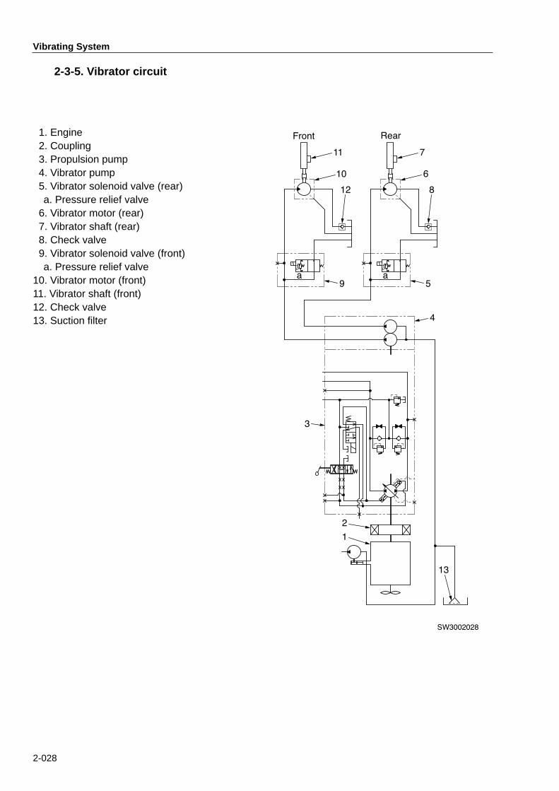
2-3-5. Vibrator circuit
SW3002028
11
10
12
9
7
6
8
a a5
4
3
2
1
13
Front Rear1. Engine2. Coupling3. Propulsion pump4. Vibrator pump5. Vibrator solenoid valve (rear)a. Pressure relief valve
6. Vibrator motor (rear)7. Vibrator shaft (rear)8. Check valve9. Vibrator solenoid valve (front)a. Pressure relief valve
10. Vibrator motor (front)11. Vibrator shaft (front)12. Check valve13. Suction filter

2-029
Vibrating System
2-3-6. Description and operation of vibrating system
Description of vibrator circuit• Made up of vibrator pump (4), front vibrator
solenoid valve (9), front vibrator motor (10),front vibrator shaft (11), rear vibratorsolenoid valve (5), rear vibrator motor (6)and rear vibrator shaft (7).
Basic function of vibrator pump andmotor:• Vibrator pump A gear pump is in use. With a gear pump, itsdisplacement is not variable.
• Vibrator motor A radial piston motor is used.
Operation• The vibrator pump discharges oil as long as
it is driven, as it is of a gear type. When thevibrator is not in use, the pump is put underno load by vibrator solenoid valves (5) and(9).
• With the vibrator switch ON, valves (5) and(9) close the unload circuit, making thevibrator operative. Vibrator motors (6) and(10) are driven. Oil displaced from themotors is dumped to the tank via checkvalves (8) and (12).
Circuit protection against high pres-sure• Pressure relief valve (a) built in vibrator
solenoid valves (5) and (9) opens to relievethe pressure if the system pressure exceedsthe setting of valve (a).

2-4. Steering system2-4-1. Hydraulic piping
SW3002029
A
9
8
2
DETAIL A
7
6
4
2
6
5
3
2
1
1. Steering pump2. Outlet hose3. Suction hose4. Steering valve (Orbitrol)5. High pressure hose (left turn)
6. High pressure hose (right turn)7. Steering cylinder8. Charge circuit hose9. Line filter
2-030
Steering System

2-031
Steering System
2-4-2. King pin
SW3002030
7
1
5
3
6
4
6
2
5
3
1. Yoke2. Bearing ass’y 3. Bracket (upper )4. Bracket (lower)5. Ball bearing6. Cover7. Grease fitting

2-032
Steering System
2-4-3. Steering valve (Orbitrol)
1. Stator2. Drive3. Spool4. Sleeve5. Cross pin6. Centering spring7. Thrust needle8. Retaining ring9. Oil seal
10. Dust seal11. Seal gland bush
12. Rotor13. End cap14. Guide15. Poppet16. Spring17. Body18. Valve seal19. Poppet20. Spring21. Plug22. O-ring23. Housing
Specifications• Valve system
: Open center non-loadreaction
• Displacement : 96.0cc/rev • Relief valve setting: 13MPa (1890psi) {133kgf/cm2}
A A
22
21
20
19
18
10 119
23
14
15
16
17
12
8
7
6
5
4
3
2
1
13
SW3002031
SECTION A-A

Steering System
2-033
2-4-4. Description and operation of Orbitrol
The steering valve (Orbitrol) is of a load-sensing type which allows the steering pumpto feed an amount of oi l into the valvecorresponding to the speed at which thesteering wheel is rotated.
Description* Valve section• The valve section makes itself a rotary type
direction control valve consisting of spool(1) and sleeve (2) as main components. Thesteering wheel is spline-connected to spool(1).
• When the steering wheel is not operated,spool (1) and sleeve (2) stay in the neutralposition with each other due to centeringsprings (6) with the oil grooves in spool (1)and oil holes in sleeve (2) not aligned. Thisblocks oil flow to the steering cylinder.
• When the steering wheel is turned, the oilgrooves in spool (1) and oil holes in sleeve(2) are aligned to feed oil to the cylinder.
* Rotor section• The rotor is an external gear which meshes
with the internal gear of stator (3). When thevalve section (spool-sleeve ass’y) opens,the rotor-stator ass’y acts as a hydraulicmotor.
• The rotation of rotor (4) is conveyed to thevalve section through drive shaft (5) spline-connected to rotor (4). An extent to whichthe valve opens is controlled by the speedat which the steering wheel is rotated.
SV4002042
8
6
7
1
2
5
4
3
Valve section
Roter section
SV4002043
3
4
SV4002044
1 2
To tank
From pump
To steeringcylinderTo steeringcylinder
Oil hole
Oil groove
1. Spool 2. Sleeve 3. Stator 4. Rotor
5. Drive shaft6. Centering spring7. Cross pin8. Check valve

Steering System
2-034
Operation* Neutral state (Steering wheel not
operated)• Centering springs (6) (flat springs) are locat-
ed in spring notches provided at end ofspool (1) and sleeve (2).
• With the steering wheel not operated, cen-tering springs (6) make the spool-sleeveass’y stay in neutral.
* This steering valve (Orbitrol) is of a load-sensing, non-load reaction, normal closetype. In the neutral position, the oil groovesand oil holes are not aligned, blocking oilflow to the steering cylinder.
* Turning (Steering wheel operated)* In neutral, all the valve holes stay closed
and oil remains trapped in the spacebetween rotor (4) and stator (3). Rotor (4) isin a fixed state, being unable to rotate in anydirection. Sleeve (2) is also unable to rotate,as it is connected to rotor (4) through crosspin (7) and drive shaft (5).
• When the steering wheel is spined, therotating force is conveyed to spool (1).Spool (1) compresses centering springs (6).Then, there is a relative movement betweenspool (1) and sleeve (2). This aligns the oilgrooves with oil holes.
• As a result, the whole ports (pump port, tankport and cylinder ports) open, allowing oilflow to related components. Rotor (4) spins.
SV4002045
6
1
2
Oil hole
Oil grooves
SV4002046
8
67
12
5
4
3
To tank
From pump
1. Spool 2. Sleeve 3. Stator 4. Rotor
5. Drive shaft6. Centering spring7. Cross pin8. Check valve
SV4002047
6
1
2
Oil hole
Oil groove

Steering System
2-035
Operation of feed back mechanism• Operation of the steering wheel creates an
angular divergence in circumferential direc-tions between spool (1) and sleeve (2) dueto centering springs (6). This makes the oilgrooves align with oil holes, allowing pumpflow into the steering valve (Orbitrol). Rotor(4) spins and feeds oil into the steeringcylinder.
• As a result, sleeve (2) rotates trailing spool(1) with an angular divergence maintainedbetween the two components. This enablesspool (1) to spin continuously with the rota-tion of the steering wheel. The machinemakes a turn continuously.
• Stopping the steering wheel operationbrings spool (1) rotation to an instant halt.However, the spool-sleeve ass’y does notget back to the neutral condition instantly.Oil continues to flow into Orbitrol, allowingrotor (4) to continue to rotate. This rotatingmotion lets sleeve (2) catch up to spool (1),blocking the hydraulic circuit to stop oil flow-ing.Finally, centering springs (6) restore thespool-sleeve ass’y to the neutral position,stopping the oil flow completely.
SV4002048

Steering System
2-036
Steering wheel rotating speed andcontrolling the flow* In the steering mechanism, it is essential to
increase or decrease oil f low into thesteering cylinder according to the rotatingspeed of the steering wheel.
• The steering valve (Orbitrol) controls the oilflow by varying the angular displacementbetween spool (1) and sleeve (2) as statedbelow: With the steering wheel rotated, sleeve (2)runs after spool (1) attempting to block thehydraulic circuit.
• The angular displacement between spool(1) and sleeve (2) increases with increasingrotating speed of the steering wheel. The oilflow increases.
Pump flow and force required to rotatesteering wheel• When the pump allows sufficient oil flow, the
force to rotate the steering wheel equals thesliding resistance offered by sleeve (2) androtor (4), etc. The steering wheel is light torotate.
• If pump flow is insufficient, the angular dis-placement between spool (1) and sleeve (2)stays maximum. The amount of oil fed torotor (4) from the pump is small. Rotor (4)spins slowly.
• For this reason, spool (1) rotates faster thanrotor (4), making the angular displacementmaximum. Spool (1) drives rotor (4) throughcross pin (7) and drive shaft (5). Then, rotor(4) acts as a hydraulic pump. A heavy steer-ing wheel results.
SW3002041
1
6
2
Small angulardisplacement
Large angulardisplacement
High steering speedLow steering speed
1. Spool 2. Sleeve 6. Centering spring

2-037
Steering System
2-4-5. Steering cylinder ass'y
2
11
12
7
8
3
9
6
4
5
10
1
11
12
SW3002034
1. Cylinder2. Piston rod3. Bush4. Piston
5. Nut6. Piston seal7. Dust seal8. Packing
9. O-ring10. O-ring11. Spherical bearing12. Lock ring
2-038
Steering System
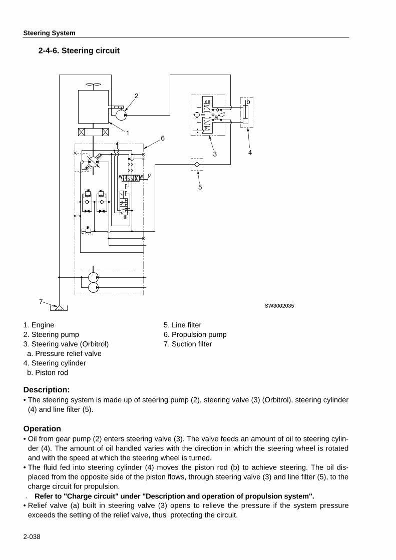
2-4-6. Steering circuit
SW30020357
2
16
43
a
b
5
1. Engine2. Steering pump3. Steering valve (Orbitrol)a. Pressure relief valve
4. Steering cylinderb. Piston rod
5. Line filter6. Propulsion pump7. Suction filter
Description:• The steering system is made up of steering pump (2), steering valve (3) (Orbitrol), steering cylinder
(4) and line filter (5).
Operation• Oil from gear pump (2) enters steering valve (3). The valve feeds an amount of oil to steering cylin-
der (4). The amount of oil handled varies with the direction in which the steering wheel is rotatedand with the speed at which the steering wheel is turned.
• The fluid fed into steering cylinder (4) moves the piston rod (b) to achieve steering. The oil dis-placed from the opposite side of the piston flows, through steering valve (3) and line filter (5), to thecharge circuit for propulsion. ★ Refer to "Charge circuit" under "Description and operation of propulsion system".• Relief valve (a) built in steering valve (3) opens to relieve the pressure if the system pressure
exceeds the setting of the relief valve, thus protecting the circuit.

Brake System
2-039
3. Brake System3-1. Brake pedal
SW3002036
4
1
3
2
5
VIEW A
3
4
1
A
2
1. Brake pedal2. Return spring3. Rod (for neutral position of F-R lever)4. Rod (for neutral position of F-R lever)5. Foot brake switch

Brake System
2-040
3-2. Description and operation of brake circuit
AC
1
5
3
4
1 3
7
6
9 8
10
SW3002037
3
1
5
4
Brake applied
Fuse
Fuse
Brake released
Rear wheel
Front wheel
From charge circuit
To oil tank
Starter switch
* Switch is OFF whenpedal is depressed.
Description:• Consists of brake pedal (1), foot brake switch
(brake release switch) (5), F-R levers (6),return-to-neutral rods (3), (4), parking brakeswitch (7), brake release solenoid (8) andparking brakes (negative brakes) (9), (10).
Operation:Parking brake switch set to position PARK-ING:• The contacts in parking brake switch (7) open
the brake release solenoid (8) circuit andclose the indicator lamp (on Combinationmeter) circuit.
• The indicator lamp comes on. The parkingbrakes (9) and (10) are applied. ★ The parking brake solenoid is deener-
gized.
Parking brake switch set to positionRELEASE:• The contacts in parking brake switch (7) close
the circuit of brake release solenoid (8) andopen the indicator lamp circuit.
• The indicator lamp comes off. The parkingbrakes (9) and (10) are disengaged. ★ The parking brake solenoid is ener-
gized.
Braking in an emergency:• Pushing down on the brake pedal (1) as far
as it will go breaks the contact in foot brakeswitch (brake release switch) (5), opening theparking brake solenoid circuit. At the sametime, the pedal movement moves either ofrods (3), (4) to bring F-R levers (6) to the neu-tral position.The parking brake solenoid is deenergized toapply the brake by means of the compressionsprings, and simultaneously, hydrostatic brak-ing takes place.
Sprinkler and Scraper
2-041
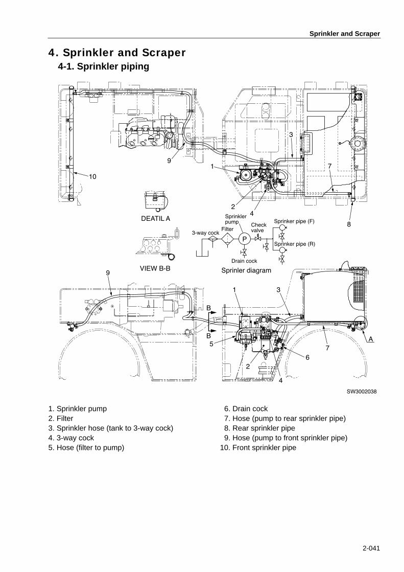
4. Sprinkler and Scraper4-1. Sprinkler piping
SW3002038
p
1/2
F
10
91
24
3
7
8
7
A
6
31
5
9
B
B
2
4
VIEW B-B
DEATIL A
P3-way cock
Filter
Sprinklerpump
Drain cock
Checkvalve
Sprinker pipe (F)
Sprinker pipe (R)
Sprinler diagram
1. Sprinkler pump2. Filter3. Sprinkler hose (tank to 3-way cock)4. 3-way cock5. Hose (filter to pump)
6. Drain cock7. Hose (pump to rear sprinkler pipe)8. Rear sprinkler pipe9. Hose (pump to front sprinkler pipe)
10. Front sprinkler pipe
Sprinkler and Scraper
2-042
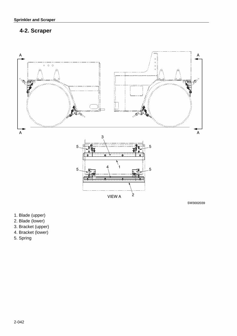
4-2. Scraper
SW3002039
A
A
A
A
3
2VIEW A
14
5
5
5
5
1. Blade (upper)2. Blade (lower)3. Bracket (upper)4. Bracket (lower)5. Spring
2-043
Electric System
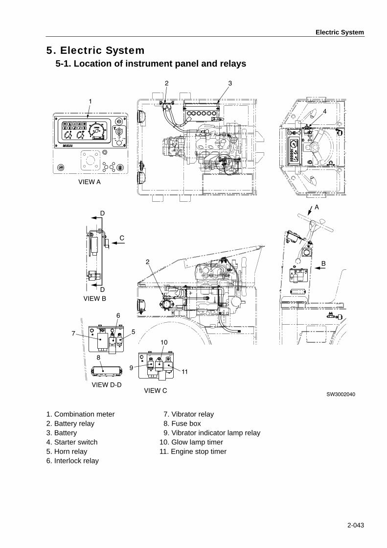
5. Electric System5-1. Location of instrument panel and relays
SW3002040
1
VIEW A
VIEW B
VIEW CVIEW D-D
2 3
4
A
B2
D
D
C
7
8
6
5
9
10
11
1. Combination meter2. Battery relay3. Battery4. Starter switch5. Horn relay6. Interlock relay
7. Vibrator relay8. Fuse box9. Vibrator indicator lamp relay
10. Glow lamp timer11. Engine stop timer

2-044
Electric System
5-2. Location of electric components
SW3002032
2
1
1211
3 4 5 6
9
10
7
8
12
13
514
16
15
1
1. Headlamp2. Brake release solenoid valve3. Engine oil pressure switch4. Starter5. Alternator6. Thermo sensor
7. Fuel gauge unit 8. Reverse alarm9. Engine revolution sensor
10. Engine stop solenoid11. Glow plug12. Vibrator solenoid valve (rear)
13. Vibrator solenoid valve (front)14. Fuse box15. Fuel pump16. Sprinkler pump relay

Electric System
2-045
5-3. Electric wiring diagram


INSPECTION & ADJUSTMENT


3-001
INSPECTION & ADJUSTMENT1.Standard Value Chart・・・・・・・・・・・・・・・・・・・・・・・・・・・・・・・・・・・・・・・・・・・・・3-002
2.Inspection & Adjustment■ 2-1. Measurement and adjustment of pressure in propulsion main circuit・・・・3-101■ 2-2. Measurement of propulsion charge circuit pressure・・・・・・・・・・・・・・・・・3-103■ 2-3. Measurement of brake release pressure・・・・・・・・・・・・・・・・・・・・・・・・・・・3-104■ 2-4. Measurement of vibrator circuit pressure ・・・・・・・・・・・・・・・・・・・・・・・・・・3-105■ 2-5. Measurement of steering circuit pressure・・・・・・・・・・・・・・・・・・・・・・・・・・3-106■ 2-6. Throttle linkage adjustment・・・・・・・・・・・・・・・・・・・・・・・・・・・・・・・・・・・・・・3-107■ 2-7. Adjustment of F-R lever linkage ・・・・・・・・・・・・・・・・・・・・・・・・・・・・・・・・・・3-108
★Precautions for Use of Standard Value Chart1) Values in the chart are based upon ones when the machine leaves the factory. They should be
used for estimation of wear after extended operation and for guidance when the machine isrepaired.
2) Values in the chart are ones based on various test results etc. They should be used as a guide tofault finding practice in due consideration of the past repair frequency and operating record of themachine.
3) Values in the chart should not be used for the standard for claim application.
★Precautions for Checking, Adjustment and Fault FindingFor checking, adjustment and fault finding practices, park the machine on level ground
and block with the safety pins or chocks.
When working with other workers, use hand signals positively and keep people not
concerned away from the work area.
Cool off the coolant or hydraulic fluid when removing the radiator cap or the hydraulic
tank filler cap. Hot fluids can burn you.
Do not put your hands close to parts in motion such as fan belts.

Standard Value Chart
3-002
1. Standard Value Chart1-1. Standard value chart for roller body
Item Measuring conditions Unit Standard valuefor new machine
Permissiblerange
Engine Speed
Low idle • Coolant temp.: Green zone on gauge
• Hydraulic oiltemperature : 50 ± 5°C(122 ± 41°C)
min-1
(rpm)
1000±50 ---------
High idle 2800±50 ---------
Rated speed 2800 ---------
Travelspeed
Forward• Engine at full throttle• Coolant temp.: Green zone on gauge
• Hydraulic oiltemperature : 50 ± 5°C(122 ± 41°C)
km/h(mile/h)
0~12(0~7.5) ←
Reverse0~12
(0~7.5) ←
Oil pressure
Propulsion
Main circuitpressure
• Engine at full throttle• Hydraulic oil
temperature : 50 ± 5°C(122 ± 41°C)
MPa(psi)
{kgf/cm2}
34.5±1.0(5000±140){352±10}
31.7(4600){324}
Charge circuitpressure
1.9±0.19(270±27){19±1.9}
1.7(240){17}
Vibrator Circuit pressure12.7±0.5
(1840±70){130±5}
11(1580){113}
Steering circuit pressure13.8±0.5
(2000±70){141±5}
11.9(1720){121}
Brake release circuitpressure
1.9±0.19(270±27){19±1.9}
1.7(240{17}
Inspection & Adjustment
3-101
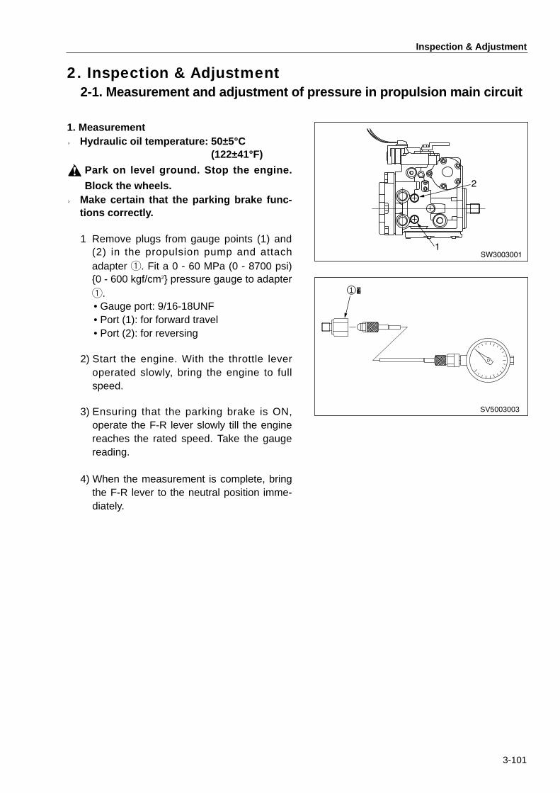
2. Inspection & Adjustment2-1. Measurement and adjustment of pressure in propulsion main circuit
SW3003001
2
1
1. Measurement★ Hydraulic oil temperature: 50±5°C
(122±41°F)
Park on level ground. Stop the engine.
Block the wheels.★ Make certain that the parking brake func-
tions correctly.
1) Remove plugs from gauge points (1) and(2) in the propulsion pump and attachadapter 1. Fit a 0 - 60 MPa (0 - 8700 psi){0 - 600 kgf/cm2} pressure gauge to adapter1. • Gauge port: 9/16-18UNF• Port (1): for forward travel • Port (2): for reversing
2) Start the engine. With the throttle leveroperated slowly, bring the engine to fullspeed.
3) Ensuring that the parking brake is ON,operate the F-R lever slowly till the enginereaches the rated speed. Take the gaugereading.
4) When the measurement is complete, bringthe F-R lever to the neutral position imme-diately.
SV5003003
①�

Inspection & Adjustment
3-102
SW3003002
8
7
2. AdjustmentIf the measured value falls outside the per-missible range, clean or renew pressure reliefvalves (7) (forward travel) and (8) (reversing).•Tightening torque for valve seat plug (9): 40 - 95 N•m (30 - 70 lbf•in) {300 kgf•cm}
★ Carefully perform disassembly andreassembly taking necessary measuresto prevent ingress of foreign matter.
SW3003003
9

Inspection & Adjustment
3-103
2-2. Measurement of propulsion charge circuit pressure
1. Measurement★ Hydraulic oil temperature: 50±5°C
(122±41°F)
Park the machine on level ground. Stopthe engine and block the wheels.
★ Make sure, before the test, that the parkingbrake works correctly.
1) Remove the plug from propulsion pumpgauge port (1) (9/16-18UNF) and mountadapter 1. Attach a 0 - 6.0 MPa (0 - 870psi) {0 - 60 kgf/cm2} pressure gauge toadapter 1.
2) Start the engine. Slowly operate the throttlelever to run the engine at maximum speed.
3) Ensuring that F-R lever is in the neutralposition, take the reading of the pressuregauge.
2. AdjustmentIf the measured value is not within the permis-sible range, adjust as follows:1) Loosen locknut (11) on the charge relief
valve. Adjust by rotating screw (12).•Clockwise rotation raises the pressure.When turned counterclockwise, the pres-sure decreases.
•A quarter turns (90 degrees) of the screwincreases or decreases the pressure by0.27 MPa (39 psi) {2.8 kgf/cm2}.
•Tightening torque for locknut: 47 - 57 N•m (34 - 42 lbf•in) {48 - 58 kgf•cm}
2) When adjustment is complete, check forcorrect setting.
3) If the valve is beyond adjustment, disas-semble and clean or renew the pressurerelief valve assembly.★ Carefully perform disassembly and
reassembly taking necessary meansto prevent ingress of foreign matter.
SW3003004
1
SV5003003
①�
SW3003005
12
11
Inspection & Adjustment
3-104
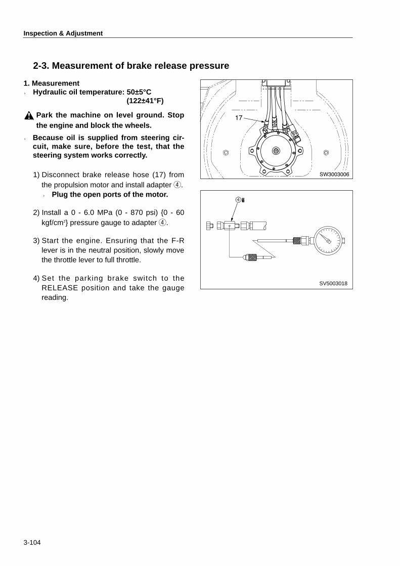
2-3. Measurement of brake release pressure
1. Measurement★ Hydraulic oil temperature: 50±5°C
(122±41°F)
Park the machine on level ground. Stopthe engine and block the wheels.
★ Because oil is supplied from steering cir-cuit, make sure, before the test, that thesteering system works correctly.
1) Disconnect brake release hose (17) fromthe propulsion motor and install adapter 4.★ Plug the open ports of the motor.
2) Install a 0 - 6.0 MPa (0 - 870 psi) {0 - 60kgf/cm2} pressure gauge to adapter 4.
3) Start the engine. Ensuring that the F-Rlever is in the neutral position, slowly movethe throttle lever to full throttle.
4) Set the parking brake switch to theRELEASE position and take the gaugereading.
SW3003006
17
SV5003018
④�

Inspection & Adjustment
3-105
2-4. Measurement of vibrator circuit pressure
1. Measurement★ Hydraulic oil temperature: 50±5°C
(122±41°F)
Park the machine on level ground. Stopthe engine and block the wheels.
1) Disconnect high pressure inlet hose (1)from the vibrator motor and mount adapter4.★Plug the open ports of the motor.
2) Install a 0 - 25 MPa (0 - 3600 psi) {0 - 250kgf/cm2} pressure gauge to adapter 4.
3) Start the engine. Slowly operate the throttlelever to run the engine at maximum speed.
4) Shift the vibration mode selector switchfrom OFF to CONT. Switch ON the vibratorswitch on top of the F-R lever and take thegauge reading.
1
SW3003007
SV5003018
④�
SW3003008
1
2
2. AdjustmentIf the measured value is not within the permis-sible range, adjust as follows:1) Loosen lock nut (1) on the relief valve and
turn adjusting screw (2). Clockwise rotationraises the pressure. The pressure lowers ifturned counter-clockwise.
2) When adjustment is complete, check forcorrect setting.
3) If the valve is beyond adjustment, disas-semble and clean or renew the pressurerelief valve assembly.★ Carefully perform disassembly and
reassembly taking necessary meansto prevent ingress of foreign matter.

Inspection & Adjustment
3-106
2-5. Measurement of steering circuit pressure
1. Measurement★ Hydraulic oil temperature: 50±5°C
(122±41°F)
Park on level ground. Stop the engine.
★ Because the return line of the steering cir-cuit feeds the charge line in the propulsioncircuit, check to see if the charge pressurein the propulsion circuit is as specified.
1) Disconnect outlet hose (1) from steeringpump. Reconnect after installing adapter 5.
2) Install a 0 - 25 MPa (0 - 3600 psi) {0 - 250kgf/cm2} pressure gauge to adapter 5.
3) Start the engine. Ensuring that the F-Rlever is in the neutral position, slowly movethe throttle lever to full throttle.
4) Turn the steering wheel counter-clockwiseto full lock. Take the gauge reading.
When rotating the steering wheel, do notallow anyone to enter the pinch area ofthe articulated frame.
2. AdjustmentIf the measured value is not within the permis-sible range, disassemble and clean or renewthe relief valve assembly built in Orbitrol. Thevalve is not adjustable.★ Carefully perform disassembly and
reassembly taking necessary means toavoid ingress of foreign matter.
SW3003009
1
SV5003021
⑤� 1

Inspection & Adjustment
3-107
2-6. Throttle linkage adjustment
★When the throttle linkage has beenrenewed (or reconnected) or if the highidle or low idle rpm is not to specification,adjust as follows:
1. Adjustment★ Coolant temperature: Green area on
gauge.
1) Set throttle lever (1) to the LOW IDLE posi-tion.
2) Connect throttle cable (2) to fuel injectionpump governor lever (3).
3) Start the engine. Slacken lock nut (4) andadjust stop bolt (5) until correct low idle rev-olution is reached.★ Low idle: 1000±50min-1 (rpm)
4) Screw in stop bolt (6) so that it makes con-tact with throttle lever (1). Then screw outby 1/4 to 1/2 turns and fix with lock nut (7).
5) Move throttle lever (1) to full throttle side.Loosen lock nut (8) and adjust stop bolt (9)to set the high idle speed to specification.
6) Start the engine and check that the highidle rpm is to specification.★High idle: 2850±50min-1 (rpm)
7) Screw in stop bolt (10) until it makes con-tact with throttle lever (1). Then screw outby 1/4 to 1/2 turns and fix with lock nut (11).
SW3003010
1
2
SW3003011
3
8 9
4
5
SW3003012
1 6
7
11
10
Inspection & Adjustment
3-108
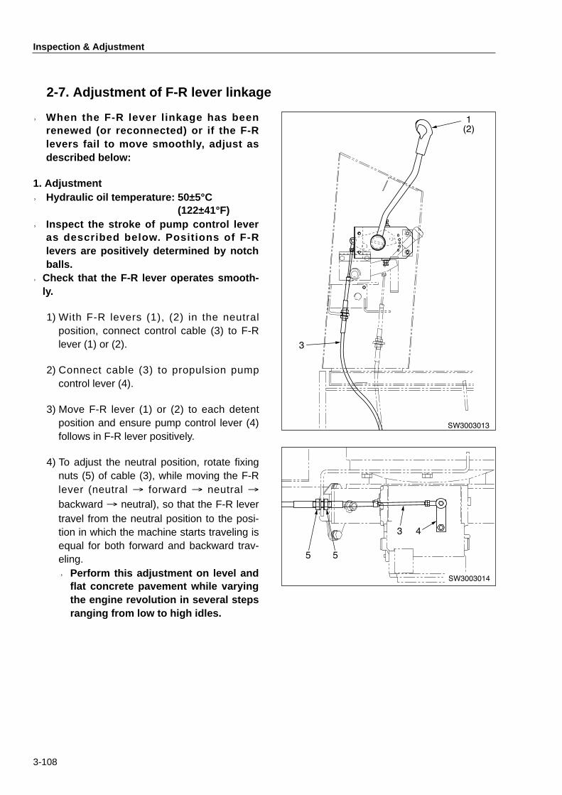
2-7. Adjustment of F-R lever linkage
★When the F-R lever linkage has beenrenewed (or reconnected) or if the F-Rlevers fail to move smoothly, adjust asdescribed below:
1. Adjustment★ Hydraulic oil temperature: 50±5°C
(122±41°F)★ Inspect the stroke of pump control lever
as described below. Positions of F-Rlevers are positively determined by notchballs.
★Check that the F-R lever operates smooth-ly.
1) With F-R levers (1), (2) in the neutralposition, connect control cable (3) to F-Rlever (1) or (2).
2) Connect cable (3) to propulsion pumpcontrol lever (4).
3) Move F-R lever (1) or (2) to each detentposition and ensure pump control lever (4)follows in F-R lever positively.
4) To adjust the neutral position, rotate fixingnuts (5) of cable (3), while moving the F-Rlever (neutral → forward → neutral →backward → neutral), so that the F-R levertravel from the neutral position to the posi-tion in which the machine starts traveling isequal for both forward and backward trav-eling.★Perform this adjustment on level and
flat concrete pavement while varyingthe engine revolution in several stepsranging from low to high idles.
SW3003013
1(2)
3
SW3003014
5 5
3 4

TROUBLESHOOTING


4-001
TROUBLESHOOTING■ 1. Precautions for Troubleshooting ・・・・・・・・・・・・・・・・・・・・・・・・・・・・・・・・・4-002
■ 2. How to Diagnose the Machine ・・・・・・・・・・・・・・・・・・・・・・・・・・・・・・・・・・・4-003
■ 3. How to use the Troubleshooting Flow ・・・・・・・・・・・・・・・・・・・・・・・・・・・・4-004
■ 4. Precautions for Diagnosis of Electric Circuit ・・・・・・・・・・・・・・・・・・・・・4-006
■ 5. Troubleshooting for Electric System (Mode E) ・・・・・・・・・・・・・・・・・・・4-201
■ 6. Fault Finding for Hydraulic and Mechanical Systems (Mode H) ・・4-401

Precautions for Troubleshooting
4-002
1. Precautions for TroubleshootingPark the machine on level ground. Make sure that the safety pins are engaged, wheelschocked and parking brake applied.
When working with other workers, use hand signals authorized, and keep people notconcerned away from the work area.
If the radiator cap is carelessly removed from a hot engine, hot coolant will gush out tocause a burn. Remove the cap only when the engine has been cooled off.
Exercise care not to touch hot parts or not to be caught in rotating parts.
When disconnecting electric wires, disconnect the battery negative (-) cable.
When taking off plugs or caps from units which are under pressure such as hydraulic,water and air pressures, do the works after removing residual pressure. If gauges areto be connected, attach them surely.
• Troubleshooting is to determine the root cause of troubles, repair faulty parts as quickly as prac-ticable, and prevent recurrence of the troubles.
• Important when conducting troubleshooting practice is of course to well understand the struc-ture and function of machines to be handled. For effective troubleshooting, however, it is ofprime importance to have a clear picture of the trouble concerned by contacting the operator.
1. When a trouble has occurred, do notattempt to disassemble blindly.Disassembling in a hurry will invite disadvan-tageous situations as described below: • Parts which need not be disassembled
may be disassembled. • Tracing the cause of trouble will become
more difficult. These will cause increased service costsbecause of wasteful service hours, spareparts or expendables like oil or grease. Tomake matters worse, such a careless prac-tice will invite operators’ (customers’) dis-trust. For these reasons, sufficient advanceinvestigations and diagnosis in accordancewith troubleshooting procedures specifiedare essential for efficient fault finding prac-tices.
2. Questions to be addressed to the opera-tor (customer) . 1) Are there any trouble other than the one
in question?2) Was there any abnormal condition with
the machine before the trouble occurs?3) Did the trouble occur suddenly without
signs of abnormal conditions in advance? 4) In what occasion did the trouble occur?5) Has the machine been repaired before
the trouble occurs? If so, when has itbeen repaired?
6) Did similar trouble occur in the past?
3. Before-diagnosis inspection1) Perform daily inspections. 2) Perform other inspections required for
diagnosis.
4. Confirmation of troubleKnow the degree of the trouble. Determinewhether it is a trouble caused by improperdesign etc. or the trouble was caused byincorrect handling.★When making the trouble recur to
trace the cause of the trouble byputting the machine in motion, usecare not to cause more damages tothe machine.
5. TroubleshootingFrom the results of items 2 to 4 above, nar-row down the cause of the trouble, and pin-point the source of the trouble by utilizingthe diagnosis flow chart.★ The basic points of the diagnosis are:1) Start from the portion simple.2) Start from the portion having a high prob-
ability to solve the problem.3) Investigate related matters.
6. Basic remedy for the trouble Even if a trouble has been rectified, it willdevelop again if its cause is not determined.It is of prime importance to trace the verycause of the trouble.

How to Diagnose the Machine
4-003
2. How to Diagnose the Machine
Procedure 1. Confirmation of trouble
1) Make an inquiry about the following items
upon request of repair.
¥ Customer's name
¥ Model and serial number of machine
¥ Work site and working condition, etc.
2) Seize outline of trouble by questioning.
¥ Details of trouble
¥ Details of work when trouble occured
¥ Working environment
¥ Information of services conducted in the
past
Procedure 2. Estimation of source of trouble
1) Determine source of trouble by referring
to "TROUBLESHOOTING" in this manual.
Procedure 3. Preparation of necessary tools
1) Prepare tools recommended in the shop
manual.
¥ Tester and extension cable, etc.
¥ Pressure gauge etc.
2) Prepare spare parts referring to the parts
catalogue.
Procedure 4. Going to site where the faulty
machine stays idle.
Procedure 7.
¥ Troubleshooting
¥ Determination of remedy
1) Before troubleshooting, find out and rectify simple
failure.
¥ Daily inspections
¥ Other inspections required
2) With reference to "TROUBLESHOOTING" in this
manual, make a diagnosis by following proper
diagnosis flows best applicable to rectify the trouble.
Procedure 5. Getting detailed information from operator
concerning the trouble
¥ Was there any abnormal signs before the trouble
occurs?
¥ Did the trouble occur all of a sudden?
¥ Was the machine repaired before?
Office and repair shop (Our side)
Procedure 6. Making the machine recur the trouble
¥ By letting the machine travel or performing the work,
check to see if the trouble is attributable to a serious
cause like the defect of component parts or the
trouble was only caused by improper handling.
Site (CustomerÕs side)
Customer Work site
Work shop
Field repair
Shop repair

How to Use this Chapter, "TROUBLESHOOTING" and How to Follow the Troubleshooting Flow
4-004
3. How to Use the Troubleshooting Flow1. Troubleshooting codes
1) Electric system: E-01 to E-142) Hydraulic and mechanical systems: H-01 to H-11
2. How to follow the troubleshooting flow
1Troubleshooting code No. and fault symptomOn top of the flow chart are code No. and fault symptom.
2General precautionsUnder the code No. and fault symptom are precautions (marked ★) for the whole items in theflow chart. Though these precautions are not indicated inside each box (□ ) which containschecking instructions, pay attention to the precautions when making inspections described in thebox (□ ).
3Sub classificationTo make diagnosis easier or for simplified flow chart, fault symptom is subclassified. Ex. a)Starter does not run
4How to forward the diagnosis• Each box ( □ ) contains diagnosis procedure. Depending upon the results of inspection or
measurement, proceed to YES or NO line.• Normally, if the result is YES then proceed to upper line. If NO then go to the lower line. NOTE: The number above each box (□ ) is a reference number. It does not mean a diagnosis
order.
Is stated voltagefed to lamp switchterminals 1 and 4that carry wire R?
Possible cause Remedy
Lighting switch faulty. Renew.
1
¥ 10~14V
NO
YES
Repair or renewwire.
Is stated voltagefed to lightingswitch terminal 2that carries wireGB?
2
¥ 10~14V NO
YES
Wire R from fuse to lightingswitch terminals 1, 4 notconnected or incorrectlyconnected (including fuse).
Repair or renewwire.
Wire GB from lighting switchterminal 2 to headlamp (tobranch point) not connectedor incorrectly connected.
1 E-08 Headlamps do not light (Example)
2 ★Measure the voltage with the starter switch ON.
3 a) Both headlamps do not come on.
4
YES
NO
1

How to Use this Chapter, "TROUBLESHOOTING" and How to Follow the Troubleshooting Flow
4-005
• As a result of diagnosis, if YES line or NO line directly goes to the description in POSSIBLECAUSE column, take necessary action as indicated in REMEDY column.
• Under each box ( □ ) are normal values and conditions necessary for inspection andadjustment. If the result gives an affirmative answer to the question in the box ( □ ) or agreesto the normal value indicated under the box, go to YES line. Otherwise, go to NO line.
• The normal values were taken from the standard value list. • For locations of component parts such as relay mentioned in the flow chart, see "Location of
key units". Line colors mentioned in the flow charts are indicated in the electric wiring diagramshown under the flow charts. In the machine, each harness is identified by color.

Precautions for Diagnosis of Electric Circuit
4-006
4. Precautions for Diagnosis of Electric Circuit
1. When disconnecting or connecting connectors or harnesses, cut the power supply.
2. Before making a diagnosis, check the connectors or harnesses for poor connection.★ If a connector is at fault, check it by repeating connection and disconnection several
times.
3. Before proceeding to the next step, reconnect removed connectors or harnesses in place.★ Care must be used for the controller circuit. If the power source is switched on with the
connector disconnected, this can cause an incorrect measurement.
4. When making a diagnosis of circuits (measurement of voltage, resistance, current, test for conti-nuity, etc.), check to see if tester readings vary by shaking connectors or harnesses.
★ If readings vary, a possible cause is a poor connection of the circuit.
5. For voltage measurement, turn the starter switch ON. For resistance checking, let the switch stayin the Off position. ★ If necessary to take a measurement of resistance by energizing relays or other units with
the starter switch ON, necessary instructions are given in the flow charts.

Troubleshooting for Electric System
4-201
■ E-01 Engine does not start ・・・・・・・・・・・・・・・・・・・・・・・・・・・・・・・・・・・・・・・・・・・・4-202■ E-02 Engine does not stop ・・・・・・・・・・・・・・・・・・・・・・・・・・・・・・・・・・・・・・・・・・・・4-205■ E-03 Glow plug does not become red-hot (difficult starting) ・・・・・・・・・・・・・・・・4-206■ E-04 No charging (charge lamp stays bright)・・・・・・・・・・・・・・・・・・・・・・・・・・・・・4-207■ E-05 Fuel pump does not work ・・・・・・・・・・・・・・・・・・・・・・・・・・・・・・・・・・・・・・・・4-207■ E-06 Reverse alarm does not sound ・・・・・・・・・・・・・・・・・・・・・・・・・・・・・・・・・・・4-208■ E-07 Horn does not sound・・・・・・・・・・・・・・・・・・・・・・・・・・・・・・・・・・・・・・・・・・・・・4-209■ E-08 Headlamps do not light ・・・・・・・・・・・・・・・・・・・・・・・・・・・・・・・・・・・・・・・・・・4-210■ E-09 Vibrator does not operate・・・・・・・・・・・・・・・・・・・・・・・・・・・・・・・・・・・・・・・・・4-211■ E-10 Sprinkler does not work ・・・・・・・・・・・・・・・・・・・・・・・・・・・・・・・・・・・・・・・・・・4-215■ E-11 Parking brake not released ・・・・・・・・・・・・・・・・・・・・・・・・・・・・・・・・・・・・・・・4-216■ E-12 Fuel gauge reads wrong ・・・・・・・・・・・・・・・・・・・・・・・・・・・・・・・・・・・・・・・・・4-217■ E-13 Water temperature gauge reads wrong ・・・・・・・・・・・・・・・・・・・・・・・・・・・・4-218■ E-14 Tachometer reads wrong ・・・・・・・・・・・・・・・・・・・・・・・・・・・・・・・・・・・・・・・・・4-219
5. Troubleshooting for Electric System (Mode E)
Wire color code
B Black BrY Brown/Yellow stripe L Blue LgY Light green/
Yellow stripe W White YL Yellow/Blue stripe
BR Black/Red stripe G Green LR Blue/
Red stripe R Red WB White/Black stripe YR Yellow/
Red stripe
BW Black/White stripe GB Green
Black stripe LW Blue/White stripe RB Red/
Black stripe WL White/Blue stripe YW Yellow/
White stripe
BY Black/Yellow stripe GL Green
Blue stripe LY Blue/Yellow stripe RG Red/
Green stripe WR White/Red stripe Gy Gray
Br Brown GR GreenRed stripe Lg Light green RL Red/
Blue stripe WY White/Yellow stripe O Orange
BrB Brown/Black stripe GW Green
White stripe LgB Light green/Black stripe RW Red/
White stripe Y Yellow Sb Sky blue
BrR Brown/Red stripe GY Green
Yellow stripe LgR Light green/Red stripe RY Red/
Yellow stripe YB Yellow/Black stripe P Pink
BrW Brown/White stripe LgW Light green/
White stripe YG Yellow/Green stripe

Troubleshooting for Electric System
4-202
1
NO
NO
YES
YES
NO
NO
YES
NO
Is stated voltagepresent at starterterminal B?
Does battery relaygive a click whenstarter switch is setfrom ON to OFFand vice versa?
Are battery voltageand fluid specificgravity asspecified?
YES
YES
NO
3
¥ Higher than 13V.
¥ Higher than 1.26(specific gravity)
¥ 10~14V
Is stated voltagepresent at starterterminal S thatcarries wire BR?
Is stated voltagepresent at batteryrelay terminal thatcarries wire LW?
Is stated voltagepresent at starterswitch terminal BRthat carries wireLgR?
Is stated voltagepresent at interlockrelay terminal thatcarries wire BR?
YES
YES
YES
NO
NO
¥ 10~14V
¥ Turn starter switchto START.
Is stated voltagepresent at batteryrelay terminal BRthat carries wireLgW?
10
11
9
¥ 10~14V
4
5
2
¥ 10~14V
¥ Turn starter switchto START.
¥ 10~14V
¥ 10~14V
E-01 Engine does not start★Set the F-R lever to the neutral position.★For voltage measurement, turn the starter switch ON.
a) Starter motor does not operate. (1/2)

Troubleshooting for Electric System
4-203
Is specified voltagefed to interlockrelay terminal thatcarries wire W?
Starter faulty.
Interlock relay faulty.
Renew.
Renew.
Renew.
Renew.
6
8 YES
NO
¥ 10~14V
¥ Turn starter switchto START.
Is specified voltagefed to starter switchterminal C thatcarries wire W?
Repair or renewwire.
Renew.
Renew.
7 YES
NO
Is specified voltagefed to interlockrelay coil terminalthat carries wireGY?
NO
YES
Repair or renewwire.
Repair or renewwire.
Safety switch on F-R leverdefective.
Starter switch defective(between B and C)
Battery relay contact faulty.
Battery relay coil faulty.
To A on page 4-204.
Battery capacity lowered.Charge orrenew battery.
Possible cause Remedy
¥ 10~14V
¥ Turn starter switchto START.
¥ 10~14V
¥ Turn starter switchto START.
Wire BR from interlock relayterminal to starter terminal Snot connected or incorrectlyconnected.
Wire W(W) from starterterminal C to interlock relaynot connected or incorrectlyconnected.
Wire from battery relay tostarter not connected orincorrectly connected.
Wire LgR (LgW) from starterswitch terminal BR to batteryrelay terminal BR notconnected or incorrectlyconnected (including fuse).
Repair or renewwire.

Troubleshooting for Electric System
4-204
Is specified voltagefed to starter switchterminal B thatcarries wire WR?
Possible cause Remedy
Starter switch faulty(between B and BR). Renew.
Is specified voltagefed to battery relayterminal thatcarries wire W?
12
13
¥ 10~14V
NO
YES
YES
NO
Repair or renewwire.Renew fuse.
Repair or renewwire.
A
¥ 10~14V
Wire WR(W) from batteryrelay terminal BR to starterswitch tereminal B notconnected or incorrectlyconnected (including fuse).
Wire from battery to batteryrelay not connected orincorrectly connected.
B
BR
C
WR W
LW
LW L
L
LgW
LgW LgW
LgR
W
BR
W BR
BR
RY GY
GR
B
S
SW3004001
SOL
3 41 2
65A
Fuse15A
Fuse15A
Fuse20A
Fuse15A
Interlock relay
Starterswitch
Battery
Battery relay
Starter
F-R lever switch
Fusible link
Engine stopsolenoid Timer
a) Starter motor does not operate. (2/2)
Electric wiring diagram for modes E-01 and E-02
Troubleshooting for Electric System
4-205
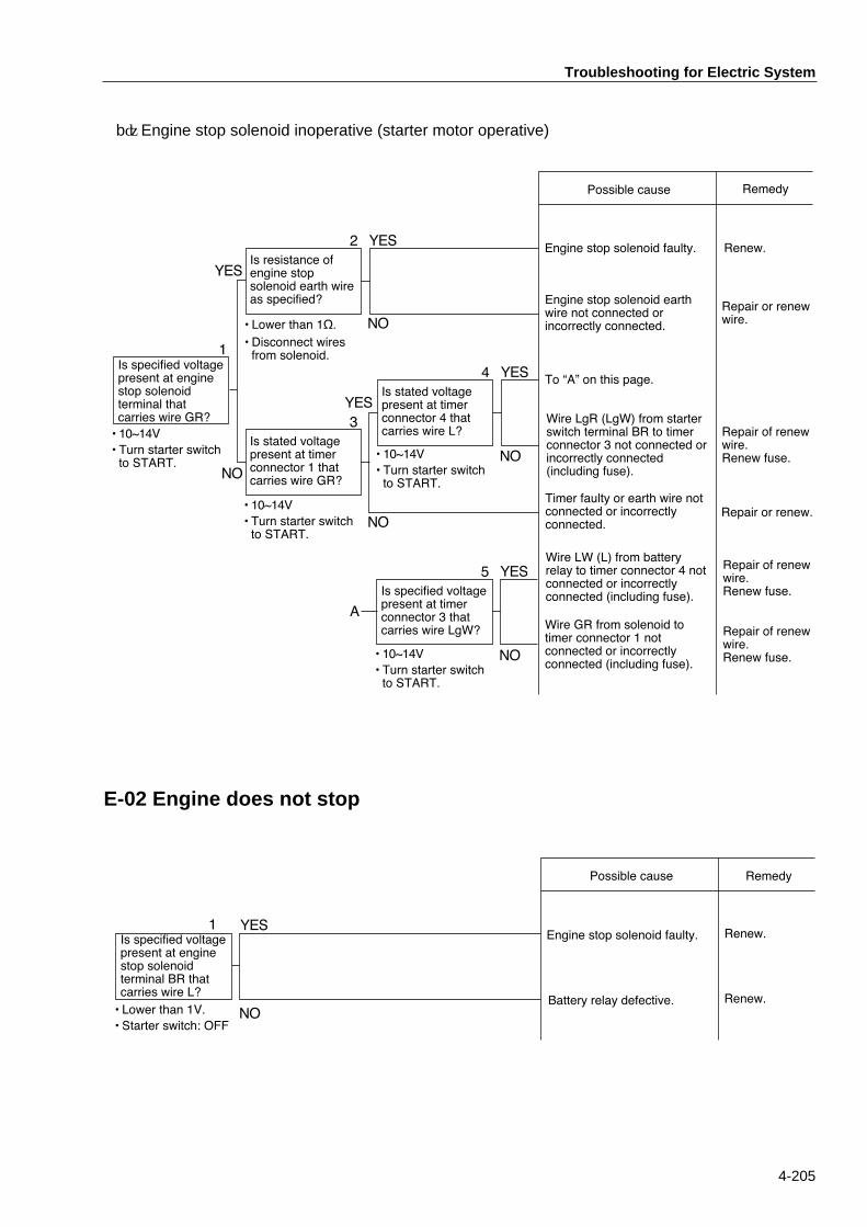
b)Engine stop solenoid inoperative (starter motor operative)
Is specified voltagepresent at enginestop solenoidterminal thatcarries wire GR?
Possible cause Remedy
Engine stop solenoid faulty. Renew.Is resistance ofengine stopsolenoid earth wireas specified?
1
2
¥ 10~14V
¥ Turn starter switchto START.
NO
NO
YES
YES
YES
NO
Is stated voltagepresent at timerconnector 4 thatcarries wire L?
4 YES
NO
Repair or renewwire.¥ Lower than 1½.
¥ Disconnect wiresfrom solenoid.
Engine stop solenoid earthwire not connected orincorrectly connected.
Repair of renewwire.Renew fuse.
Wire LgR (LgW) from starterswitch terminal BR to timerconnector 3 not connected orincorrectly connected(including fuse).
Is stated voltagepresent at timerconnector 1 thatcarries wire GR?
3
Is specified voltagepresent at timerconnector 3 thatcarries wire LgW?
5 YES
NO
¥ 10~14V
¥ Turn starter switchto START.
¥ 10~14V
¥ Turn starter switchto START.
To ÒAÓ on this page.
Timer faulty or earth wire notconnected or incorrectlyconnected.
Repair or renew.
¥ 10~14V
¥ Turn starter switchto START.
Wire LW (L) from batteryrelay to timer connector 4 notconnected or incorrectlyconnected (including fuse).
Repair of renewwire.Renew fuse.
Repair of renewwire.Renew fuse.
Wire GR from solenoid totimer connector 1 notconnected or incorrectlyconnected (including fuse).
A
E-02 Engine does not stop
Is specified voltagepresent at enginestop solenoidterminal BR thatcarries wire L?
Battery relay defective.
1
¥ Lower than 1V.
¥ Starter switch: OFFNO
YES
Possible cause Remedy
Engine stop solenoid faulty. Renew.
Renew.

Troubleshooting for Electric System
4-206
E-03 Glow plugs do not become red-hot (difficult starting)★It is assumed that the starter is normal.★Measure the voltage with the starter switch ON.
a) Glow lamp does not become bright. (Other lamps light up.)★The glow indicator should become bright when the starter switch is turned to the
HEAT position, and come off when preheating is complete.
YES
1
NO
Does statedvoltage appear atglow lamp timerconnector 4 thatcarries wire WG.
Does statedvoltage appear atglow lamp timerconnector 6 thatcarries wire YW?
Possible cause Remedy
4
¥ Starter switchON: 10 to 14VHEAT: Lower
than 1V.
Glow lamp relay faulty.
Glow indicator faulty.
¥ 10~14V
¥ Turn starter switchto HEAT.
2YES
NO
Starter switch faulty(between B and R2).
Renew.
Renew.
Does statedvoltage appear atstarter switchterminal R2 thatcarries wire WG?
NO
YES
Repair or renewwire.
Renew.
3 YES
NO
Does statedvoltage appear atcombination meterterminal thatcarries wire YW?
Does statedvoltage appear atglow plug terminalthat carries wireWG?
Glow plug faulty. Renew.1
NO
YES
¥ 10~14V
¥ Turn starter switchto HEAT.
¥ 10~14V
¥ Turn starter switchto HEAT.
¥ Starter switchON: 10 to 14VHEAT: Lower than 1V.
Wire YW from combinationmeter to glow lamp timerconnector 6 not connected orincorrectly connected.
Wire WG from starter switchterminal R2 to glow plug notconnected or incorrectlyconnected.
Repair or renewwire.
Repair or renewwire.
Wire WG from starter switchterminal R2 to glow plug notconnected or incorrectlyconnected.
b) Glow indicator becomes bright but hard starting
Electric wiring diagram for mode E-03
CB
ACCR2
R1
WG
WG
WL
BrB
Y
43 5 6
YW
SW3004002
5A
Starter switch
Glow plugs
Glow indicatorFrom batteryrelay
Glow lamptimer
Combination meter
Fuse

Troubleshooting for Electric System
4-207
E-04 No charging (charge lamp stays bright.)★Measure the voltage with the starter switch ON.
Does specifiedvoltage appear atalternator terminalIG that carries wireY?
Possible cause Remedy
Regulator faulty.
Alternator faulty.
Renew.
Does specifedvoltage appear atalternator terminalB that carries wireWY?
1
¥ 13.5~14.5V
¥ Run engine athigher thanmedium speed.
¥ 10~14V
NO
YES
YES
NO
Repair or renewwire.
2Renew.
Wire WY from alternatorterminal B to starter terminalB not connected orincorrectly connected.
Electric wiring diagram for mode E-04
B ACC
BrB
WR
Y
Y
SW3004003
5A
B
B
IG
LE
WYY
WR
Fuse
Charge lamp
Starter
Alternator
Combination meter
Starter switch
From batteryrelay
E-05 Fuel pump does not work★Measure the voltage with the starter switch ON.
Does specifiedvoltage appear atfuel pump terminalthat carries wireRB?
Is resistance of fuelpump earth wire asspecified?
Fuel pump faulty.
1
2
¥ 10~14V
¥ Lower than 1½.
¥ Disconnect wiresfrom pump.
NO
NO
YES
YES
Possible cause Remedy
Renew.
Repair or renewwire.
Repair or renewwire.
Fuel pump earth wire notconnected or incorrectlyconnected.
Wire RB from fuse to fuelpump not connected orincorrectly connected.
Electric wiring diagram for mode E-05
SW3004004
Fuse
15A RBR
B

Troubleshooting for Electric System
4-208
Electric wiring diagram for mode E-06
RG BY BY R
SW3004005
NOFuse15A
Back-up switchReverse alarm
E-06 Reverse alarm does not sound★First, check that the fuse is not blown.★The voltage measurement should be taken with the starter switch ON.
YES
NO
1
YES
NO
Does specifiedvoltage appear atreverse alarmterminal thatcarries wire BY?
Possible cause Remedy
Wire BY from back-up switchto reverse alarm not connectedor incorrectly connected.3
Reverse alarm earth wire notconnected or incorrectlyconnected.¥ Less than 1½
¥ Disconnect wire fromreverse alarm.
Reverse alarm faulty.
¥ 10~14V¥ Move F-R leverBACKWARD.
2
YES
NO
Is resistance ofreverse alarmground wire asspecified?
Wire RG from back-up switchto fuse not connected orincorrectly connected.
Renew.
Repair or renewwire.
Does specifiedvoltage appear atback-up switch thatcarries wire BY?
Repair or renewwire.
Back-up switch faulty. Renew.
Repair or renewwire.
4 YES
NO¥ 10~14V
Is specified voltagepresent at back-upswitch terminal thatcarries wire RG?
¥ 10~14V¥ Move F-R leverBACKWARD.

Troubleshooting for Electric System
4-209
E-07 Horn does not sound★First, check that fuse is not blown.★The voltage measurement should be taken with the starter switch ON.
YES
NO
1
YES
NO
Is stated voltagepresent at hornterminal thatcarries wire Lg?
Possible cause Remedy
3
Horn earth wire not connectedor incorrectly connected.¥ Lower than 1½.
¥ Disconnect wirefrom horn.
Horn faulty.
¥ 10~14V
¥ Switch on hornswitch.
2
YES
NO
Is resistance ofhorn earth wire asspcified?
Renew.
Is stated voltagepresent at hornrelay terminal thatcarries wire Lg?
Repair or renewwire.
To ÒAÓ on this page.4 YES
NO¥ 10~14V
Is stated voltagepresent at hornrelay terminal thatcarries wire RG?
A
Horn relay faulty.
Horn switch earth wire notconnected or incorrectlyconnected.
Horn switch faulty.
¥ 10~14V
¥ Switch OFF hornswitch.
Is stated voltagepresent at hornswitch terminal thatcarries wire LgW?
Is resistancebetween hornswitch terminalsnormal?
YES
NO
5¥ Lower than 1½when switched ON.
¥ Disconnect wiresfrom horn switch.
YES
NO
6
7
8 YES
NO¥ 10~14V
¥ Switch OFF hornswitch.
Is stated voltagepresent at hornrelay coil terminalthat carries wireLgW?
Is resistance ofhorn switch earthwire as specified?
¥ Lower than 1½.¥ Disconnect wiresfrom horn switch.
YES
NO
¥ 10~14V
¥ Switch on hornswitch.
Wire Lg from horn to hornrelay not connected orincorrectly connected.
Repair or renewwire.
Repair or renewwire.
Wire RG from fuse to hornrelay terminal not connectedor incorrectly connected.
Renew.
Repair or renewwire.
Renew.
Repair or renewwire.
Renew.
Wire LgW from horn relay coilto horn switch not connectedor incorrectly connected.
Horn relay coil defective orwire RG from horn relay coilto fuse ( from branch point)not connected or incorrectlyconnected.
Electric wiring diagram for mode E-07
RG Lg Lg
LgW
SW3004006
RG
RG
Fuse15A
Horn relay
Horn button
Horn

Troubleshooting for Electric System
4-210
E-08 Headlamps do not light★Measure the voltage with the starter switch ON.
a) Both headlamps do not come on.
Is stated voltagefed to lamp switchterminals 1 and 4that carry wire R?
Possible cause Remedy
Lighting switch faulty. Renew.
1
¥ 10~14V
NO
YES
Repair or renewwire.
Is stated voltagefed to lightingswitch terminal 2that carries wireGB?
2
¥ 10~14V NO
YES
Is filament of bulbburnt?
Filament is burnt. Renew.1
Is stated voltagefed to inoperativelamp terminal thatcarries wire GB?
2
NO
YES
YES
NO
¥ Repair.
¥ Repair or renewwire.
Wire R from fuse to lightingswitch terminals 1, 4 notconnected or incorrectlyconnected (including fuse).
Repair or renewwire.
Wire GB from lighting switchterminal 2 to headlamp (tobranch point) not connectedor incorrectly connected.
¥ 10~14V
¥ Lighting switch:Select headlamp.
Poor contact of bulb or earthwire not connected orincorrectly connected.
Wire GB from lighting switchterminal 2 to headlamps(from branch point) notconnected or incorrectlyconnected.
Repair or renewwire.
b) Either left or right headlamp does not come on.
1
4
3
5
62R
SW3004007
GB GB R
RGB
Fuse30A
Headlamp
Lighting switch
Headlamp
Combination meter
Instrument panel lamp
Electric wiring diagram for mode E-08

Troubleshooting for Electric System
4-211
Electric wiring diagram for mode E-09
SW3004008
2
6
5
31
4
E FGGY
Br
Br
Br
Br
(F)
Br
RW RWRL BrB
B
B
B BrR
B
RL
RLRLRr
BrR
BrR
BrR BrY
BrY
H
X DX B
Fuse15A
Vibrator relay
Vibrator switch (R)
Vibrator switch (L)
Vibration modeselector switch
Vibrator solenoid (R)
Vibrator solenoid (F)
F-R
leverswitch
Vibrator indicatorlamp
Vibrator indicatorlamp relay
Fuse15A
E-09 Vibrator does not operate ★Measure the voltage with the starter switch ON.
a) Inoperative in MANUAL mode.★Diagnose with vibration mode selector switch set to MANUAL.
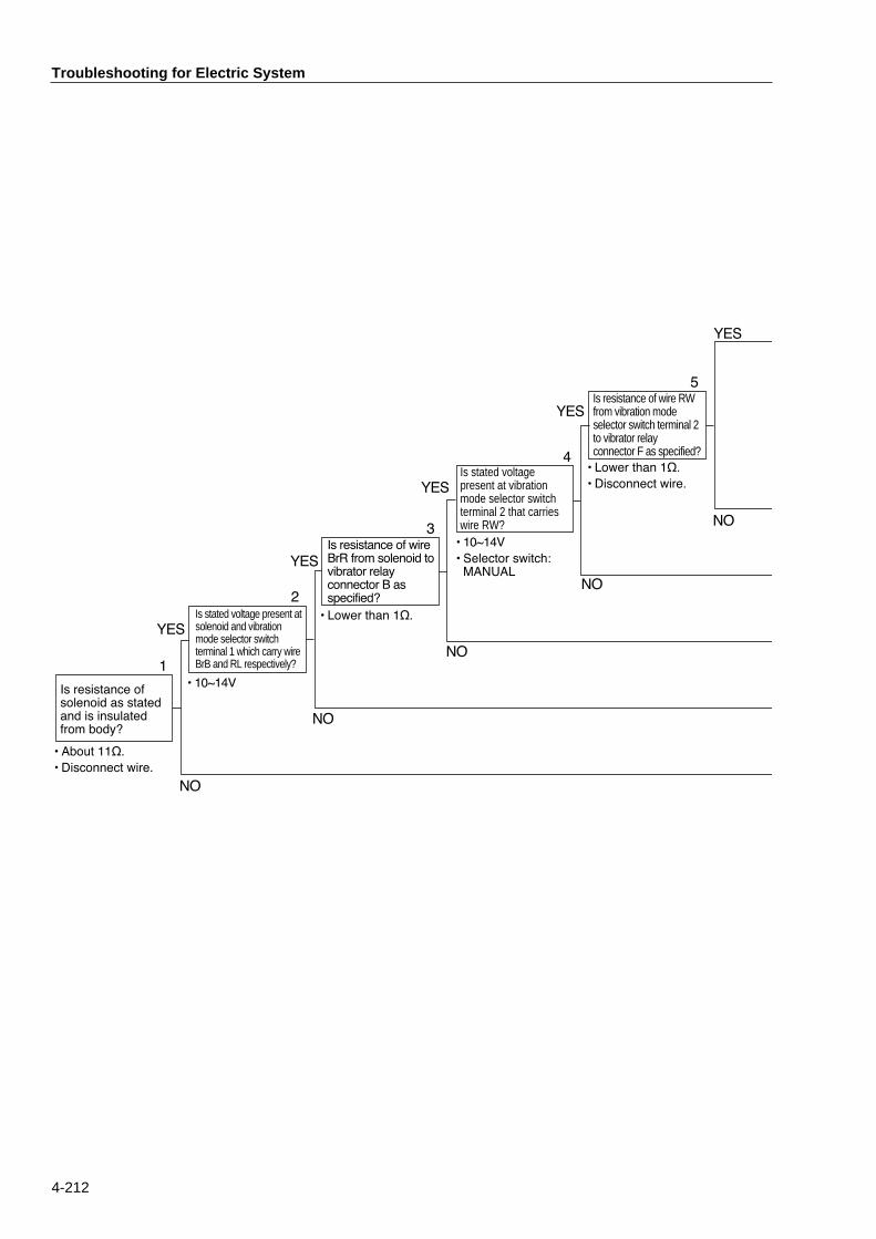
Troubleshooting for Electric System
4-212
1
NO
YES
NO
Is resistance of wire RW from vibration mode selector switch terminal 2 to vibrator relay connector F as specified?
Is resistance ofsolenoid as statedand is insulatedfrom body?
YES
NO
YES
5
¥ Lower than 1½.
¥ Disconnect wire.
¥ About 11½.
¥ Disconnect wire.
¥ 10~14V
¥ Selector switch:MANUAL
¥ Lower than 1½.Is stated voltage present at solenoid and vibration mode selector switch terminal 1 which carry wire BrB and RL respectively?
3
Is stated voltage present at vibration mode selector switch terminal 2 that carries wire RW?
Is resistance of wireBrR from solenoid tovibrator relayconnector B asspecified?
YES
4
NO
YES
NO
2
¥ 10~14V

Troubleshooting for Electric System
4-213
Is stated voltagepresent at vibratorswitch that carrieswire Br?
Possible cause Remedy
Vibrator switch faulty.
Vibrator relay faulty.
Renew.
6
¥ 10~14V
YES
Renew.
Renew.
Repair or renewwire.
7
NO
YES
Repair or renewwire.
Is resistance ofvibrator switchearth wire asspecified?
8
NO
YESIs resistance of wireBr from vibratorswitch to vibratorrelay connector Has specified?
Wire Br from vibrator switchto vibrator relay connector Hnot connected or incorrectlyconnected.
Repair or renewwire.
Renew.
Wire RW from vibration modeselector switch to vibratorrelay connector F notconnected or incorrectlyconnected.
Repair or renewwire.
Wire BrR from vibratorsolenoid to vibrator relayconnector B not connected orincorrectly connected.
NO
Solenoid faulty.
¥ Lower than 1½.¥ Disconnect wires.
¥ Lower than 1½.¥ Disconnect wires.
Vibrator switch earth wire notconnected or incorrectlyconnected.
Vibration mode selector switchfaulty.
Repair or renewwire.
Wire RL (BrB) from vibrationmode selector switch terminal1 to fuse not connected orincorrectly connected.

Troubleshooting for Electric System
4-214
b) Inoperative in AUTO mode (Operative in MANUAL mode) ★Set vibration mode selector switch to AUTO.
Is stated voltagepresent at vibrationmode selectorswitch terminal 4that carries wire RL?
Is stated voltage present at vibration mode selector switch terminal 5 that carries wire BrY?
Is resistance of wire BrY from vibration mode selector switch terminal 5 to vibrator relay connector G as specified?
Possible cause Remedy
3To ÒAÓ on this page.
1
2
YES
YES
NO
NO
YES
NO
¥ 10~14V
Repair or renewwire.
Renew.
Is resistance of wireGY from vibratorrelay connector E toF-R lever switch asspecified?
¥ Lower than 1½.¥ Disconnect wires.
4 YES
NO
A
¥ 10~14V
Wire BrY from vibrator relayconnector G to selectorswitch not connected orincorrectly connected.
Wire RL from vibration modeselector switch termianl 4 tofuse not connected orincorrectly connected.
¥ Repair or renewwire.
¥ Renew fuse.
Repair or renewwire.
Renew.
Wire GY from vibrator relayconnector E to F-R leverswitch not connected orincorrectly connected.
¥ Lower than 1½.¥ Disconnect wires.
Vibration mode selector switchfaulty.
Vibrator relay faulty.

Troubleshooting for Electric System
4-215
E-10 Sprinkler does not work★Measure the voltage with the starter switch ON.
YES
NO
1
YES
NO
Is specified voltagepresent at sprinklermotor that carrieswire LB?
Possible cause Remedy
3
¥ Lower than 1½.¥ Disconnect wirefrom motor.
Sprinkler motor faulty.
¥ 10~14V¥ Operate sprinklerswitch.
2
YES
NO
Is resistance ofsprinkler motorearth wire asspecified?
Renew.
Is specified voltagepresent at sprinklerrelay terminal thatcarries wire LB?
Repair or renewwire.
To ÒAÓ on this page.4 YES
NO¥ 10~14V
Is specified voltagepresent at sprinklerrelay terminal thatcarries wire LY?
A
Sprinkler relay faulty. Renew.
Sprinkler relay earth wire notconnected or incorrectlyconnected.
Sprinkler switch faulty. Renew.
Is specified voltagepresent at sprinklerrelay coil thatcarries wire LW?
Is resistance ofsprinkler relayearth wire asspecified?
YES
NO
5
YES
NO
6
7
8
YES
YES
NO
NO
Is specified voltagepresent at sprinklerswitch terminal 2that carries wireLW? Is specified voltage
present at sprinklerswitch terminal 1that carries wireLY?
¥ 10~14V
Sprinkler motor earth wire notconnected or incorrectlyconnected.
Repair or renewwire.
Wire LB from sprinkler relayto sprinkler motor notconnected or incorrectlyconnected.
Repair or renewwire.
Wire LY from fuse to sprinklerrelay not connected orincorrectly connected.
¥ Lower tnan 1½.¥ Disconnect wirefrom relay.
Repair or renewwire.
Repair or renewwire.
Wire LW from sprinkler switchterminal 2 to sprinkler relaycoil not connected orincorrectly connected.
Repair or renewwire.
Wire LY from fuse to sprinklerswitch terminal 1 (frombranch point) not connectedor incorrectly connected.
¥ 10~14V¥ Operate sprinklerswitch.
¥ 10~14V¥ Operate sprinklerswitch.
¥ 10~14V¥ Operate sprinklerswitch.
Electric wiring diagram for mode E-10
SW3004009
1
2
3
LW
LY LY
LW
LW
LY
LB Or BM
Fuse20A
Sprinkler switch
Sprinkler relay Sprinkler motor
Sprinklerindicatorlamp
Combination meter

Troubleshooting for Electric System
4-216
E-11 Parking brake not released★Measure the voltage with the starter switch ON.★Set the parking brake to DISENGAGE and keep the foot brake pedal not depressed.
YES
1
NO
Is stated voltagepresent at brakerelease solenoidterminal thatcarries wire WB?
Possible cause Remedy
Brake release solenoid faulty.
4
¥ About 8.5 ½.¥ Disconnect wiresfrom solenoid.
¥ 10~14V¥ Set parking brakeswitch to RELEASE.
2
YES
YES
NO
NO
Is solenoidresistance asspecified and issolenoid insulatedfrom body?
Is stated voltagepresent at parkingbrake switchterminal 3 thatcarries wire WB? Is stated voltage
present at parkingbrake switchterminal 1 thatcarries wire RW?
Repair or renewwire.
Renew.
Parking brake switch faulty.
To ÒAÓ on this page.
Renew.
Foot brake switch faulty.
5 YES
NO
3 YES
NO
¥ 10~14V
6
YES
NO
Is stated voltagepresent at footbrake switch thatcarries wire RW?
Is stated voltagepresent at footbrake switch thatcarries wire RY?
7 YES
NO
A
Is resistance ofsolenoid earth wireas specified?
¥ Lower than 1½.¥ Disconnect wiresfrom solenoid
¥ 10~14V
Hydraulic system faulty(Use H-08.)
Brake release solenoid earthwire not connected orincorrectly connected.
Repair or renewwire.
Wire WB from brake releasesolenoid to parking brakeswitch terminal 3 notconnected or incorrectlyconnected.
¥ 10~14V
¥ 10~14V
Wire RW from parking brakeswitch terminal 1 to footbrake switch not connectedor incorrectly connected.
Repair or renewwire.
Renew.
Wire RY from fuse to footbrake switch not connectedor incorrectly connected.
Repair or renewwire.
Electric wiring diagram for modes E-11
WB
SW3004010
3
5
1
4
RY
YL
RW NCFuse15A
Parking brakerelease solenoid Foot brake switchParking brake swistch
Parking brakeindicator lamp
Combination meter
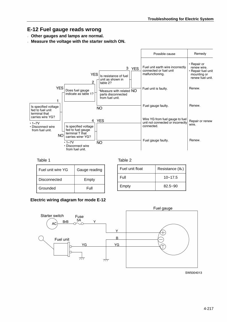
Troubleshooting for Electric System
4-217
E-12 Fuel gauge reads wrong★Other gauges and lamps are normal. ★Measure the voltage with the starter switch ON.
1
Possible cause Remedy
Fuel unit is faulty.
Fuel unit earth wire incorrectlyconnected or fuel unitmalfunctioning.
2
Renew.
¥ Repair orrenew wire.¥ Repair fuel unitmounting orrenew fuel unit.
Fuel gauge faulty.
YES
NO
Is resistance of fuelunit as shown intable 2?
Does fuel gaugeindicate as table 1?
Is specified voltagefed to fuel gaugeterminal T thatcarries wirer YG?
*Measure with relatedparts disconnectedfrom fuel unit.
Is specified voltagefed to fuel unitterminal thatcarries wire YG?
YES
YES
NO
NO
4 Wire YG from fuel gauge to fuelunit not connected or incorrectlyconnected.
Repair or renewwire.
YES
NO
3
Renew.
Fuel gauge faulty. Renew.
¥ 1~7V¥ Disconnect wirefrom fuel unit.
¥ 1~7V¥ Disconnect wirefrom fuel unit.
Electric wiring diagram for mode E-12
Fuse5A Y
Y
YGYG
B
SW5004013
ACBrB
Starter switch
Fuel unit
Fuel gauge
Table 1 Table 2
Fuel unit wire YG Gauge reading
Disconnected Empty
Grounded Full
Fuel unit float Resistance (Ω)
Full 10~17.5
Empty 82.5~90
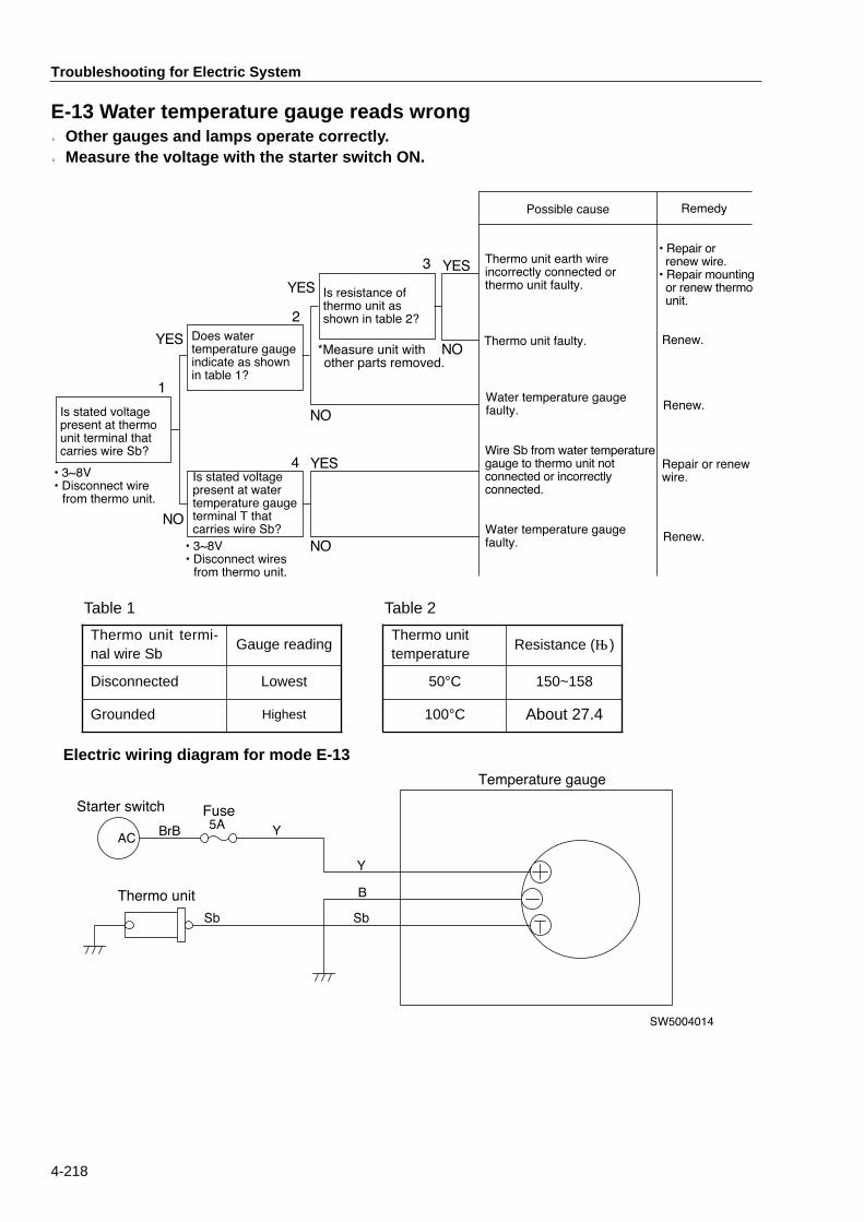
Troubleshooting for Electric System
4-218
E-13 Water temperature gauge reads wrong★Other gauges and lamps operate correctly.★Measure the voltage with the starter switch ON.
1
Possible cause Remedy
Thermo unit faulty.
Thermo unit earth wireincorrectly connected orthermo unit faulty.
2
Renew.
¥ Repair orrenew wire.¥ Repair mountingor renew thermounit.
Water temperature gaugefaulty.
YES
NO
Is resistance ofthermo unit asshown in table 2?
Does watertemperature gaugeindicate as shownin table 1?
Is stated voltagepresent at watertemperature gaugeterminal T thatcarries wire Sb?
*Measure unit withother parts removed.
Is stated voltagepresent at thermounit terminal thatcarries wire Sb?
YES
YES
NO
NO
4
¥ 3~8V¥ Disconnect wiresfrom thermo unit.
Wire Sb from water temperaturegauge to thermo unit notconnected or incorrectlyconnected.
Repair or renewwire.
YES
NO
3
Renew.
Water temperature gaugefaulty. Renew.
¥ 3~8V¥ Disconnect wirefrom thermo unit.
Electric wiring diagram for mode E-13
Sb
Fuse5A Y
Y
Sb
B
SW5004014
ACBrB
Starter switch
Thermo unit
Temperature gauge
Table 1 Table 2
Thermo unit termi-nal wire Sb
Gauge reading
Disconnected Lowest
Grounded Highest
Thermo unittemperature
Resistance (Ω)
50°C 150~158
100°C About 27.4

Troubleshooting for Electric System
4-219
E-14 Tachometer reads wrong★Other gauges and lamps operate correctly.★Measure the voltage with the starter switch ON.
1
Possible cause Remedy
To ÒAÓ on this page.
Tachometer unit incorrectlyfitted.2
YES
NO
Is resistance ofwire YR betweentachometer sensorand tachometer asspecified?
Is specifed voltagefed to tachometerterminal (+) thatcarries wire Y?
Is fault corrected iftachometer unit isrefitted?
¥ Lower than 1½.
¥ Disconnect wires.
Is continuity oftachometer sensornormal (gives 4signals perrotation)?
YES
NO
Repair or renewwire.
YES
NO
3
YES
NO
4
Refit correctly.
Renewcombinationmeter.
Tachometer sensor faulty.
Tachometer sensormalfunctions.
Feed wire inside combinationmeter is faulty
Renew.
¥ Remove unit androtate its shaft byhand.
A
Wire YR from tachometersensor to tachometer notconnected or incorrectlyconnected.
Renewcombinationmeter.¥ 10~14V
Electric wiring diagram for mode E-14
YR
Fuse5A
Y
YR
B
+
P
SW5004015
ACBrB
Starter switch
Tachometer sensor
Tachometer
-

MEMO

Fault Finding for Hydraulic and Mechanical Systems
4-401
6. Fault Finding for Hydraulic and Mechanical Systems(Mode H)
■ H-01 Noisy (unusual sounds) ・・・・・・・・・・・・・・・・・・・・・・・・・・・・・・・・・・・・・・・・4-404■ H-02 Hot hydraulic oil・・・・・・・・・・・・・・・・・・・・・・・・・・・・・・・・・・・・・・・・・・・・・・・4-404■ H-03 Not propelled ・・・・・・・・・・・・・・・・・・・・・・・・・・・・・・・・・・・・・・・・・・・・・・・・・4-405■ H-04 Speed not gained or low traction ・・・・・・・・・・・・・・・・・・・・・・・・・・・・・・・・4-407■ H-05 Vibrator does not work ・・・・・・・・・・・・・・・・・・・・・・・・・・・・・・・・・・・・・・・・・4-409■ H-06 Weak vibration force・・・・・・・・・・・・・・・・・・・・・・・・・・・・・・・・・・・・・・・・・・・4-409■ H-07 Steering not performed・・・・・・・・・・・・・・・・・・・・・・・・・・・・・・・・・・・・・・・・・4-410■ H-08 Heavy or slow steering・・・・・・・・・・・・・・・・・・・・・・・・・・・・・・・・・・・・・・・・・4-410■ H-09 Parking brake not released ・・・・・・・・・・・・・・・・・・・・・・・・・・・・・・・・・・・・・4-411■ H-10 Parking brake is not applied sufficiently・・・・・・・・・・・・・・・・・・・・・・・・・・・4-411■ H-11 No sprinkling on tires・・・・・・・・・・・・・・・・・・・・・・・・・・・・・・・・・・・・・・・・・・・4-412

Fault Finding for Hydraulic and Mechanical Systems
4-402
Trouble modes for hydraulic and mechanic systems and sources of trouble
Trouble mode
Source-of-trouble units
Unusualsounds
Hydraulicfluid toohot
Propulsion
Not propelleda) Forward and
reverseb) Either forward
or reverse
Propulsion
Pump
Propulsion pump ● ●Charge pump (Steering pump) ●
Servo valve/servolinkage ● ●
High pressure reliefvalve ●
Charge relief valve ●
Frontmotor
Motor unit ● ● ●Negative brake(parking brake) ●
Drum ●
Rearmotor
Motor unit ● ● ●Negative brake(parking brake) ●
Drum ●Brake valve ●
Vibrator
Rear
Pump
Motor unit
Vibrator
Vibrator solenoid valve(pressure relief valve)
Front
Pump
Motor unit
Vibrator
Vibrator solenoid valve(pressure relief valve)
Steering
Steering pump
Steering valve (Orbitrol)
Pressure relief valve
Steering cylinder
Steering mechanism
Steering column
SprinklerSprinkler pump
Hose/Valve/Nozzle/Filter
Others
F-R lever linkage ● ●Oil cooler ●Coupling ● ●Filter/piping, etc. ● ●
Diagnosis code H-01 H-02 H-03a H-03b H-04a
●
●
●
●
●
●
●●
●
●
●
a) Forward andreverse
Speed not gained or low traction
H-04b
●
●
●
●
●
b) Either forwardor reverse

Fault Finding for Hydraulic and Mechanical Systems
4-403
Vibrator does not work
Week vibratingforce
Parking brakeis not appliedsufficiently
No sprinklingon tires
Not performed Heavy or slow
● ●
● ●
● ●● ●● ●●
● ●
● ●● ●●
● ●
● ●●● ●
●● ●
●●●
SteeringParking brakeis not released
H-05 H-06 H-07 H-08 H-09 H-10 H-11

Fault Finding for Hydraulic and Mechanical Systems
4-404
H-01 Noisy (Unusual sounds)
Possible cause Remedy
1
3 YES
NO
Is pumpsuction hoseloose?NO
YES
Loose suction hose clamp.
Repair or renew.2
Is noisecoming fromfront ofpump?
Around pump.
5 YES
NO
Are foreignmaterials ormetal chipsnoticeable inhydraulic oil?
6 YES
NO
Are bearingsor boltsloose?
NO
YES4
Is suctionfilterclogged?
A
Where isnoise comingfrom?
Internal fault of propulsionmotor (Diagnose from item4 above.)
Coupling faulty.
Retighten.
To ÒAÓ on this page.
Filter clogged. Clean or renew.
Propulsion pump or motorfaulty. Inspect.
Operate machine for sometime and inspect change offaulty condition.
Around drum.
Loose bearings or fixing bolts,etc.
Remove drumand inspect.
H-02 Hot hydraulic oil
Is machinehandled asinstructed byoperatorÕs manual?
Possible cause Remedy
3
Collaped or clogged piping.
1
2
YES
NO
YES
NO
Are other faultsymptonsnoticeable?
NO
YES
Improper handling.(Overload operation etc.) Handle correctly.
Is oil coolerclogged?
Diagnose by using relatedtrouble mode.
Clean or renew.
¥ Such as slow speedand low traction
Oil cooler clogged.
Clean or renew.

Fault Finding for Hydraulic and Mechanical Systems
4-405
H-03 Not Propelled★Diagnose electric systems first then proceed as follows.★First, check the oil level of the hydraulic tank.
a) Not propelled in both directions.
Is bypass valvecompletely closed?
2Servo valve and servo linkagemalfunction.Does F-R lever
move adequately?1
YES
NO
Adjust.
NO
YESDo pump servovalve and servolinkage functioncorrectly?
Is charge pressurenormal?
4
YES
NO
3
YES
NO
YESRelease brake byscrewing releasebolt. Does machinerun?
NO
6
YES
NO
Block port A andport B of rearmotor. Does frontmotor run?
9
F-R lever linkage not adjustedcorrectly.
Repair or renew.
Clean or renew.
Adjust or renew.
5
Is parking brakerelease pressureas specified?
NO
YES
YES
Bypass valve partly open.
Charge relief valvemalfunctions due to presenceof dust etc.
YES
NO
Disassemble andclean charge reliefvalve. Is it restoredto normalcondition?
7
YES
NO
Block port A andport B of frontmotor. Does rearmotor run?
8
B
A
Rear motor faulty.
Possible cause Remedy
To ÒAÓ on this page.
¥ See STANDARDVALUE CHART.
¥ See STANDARDVALUE CHART.
¥ Do this workseparately for leftand right brake units.
Parking brake faulty.
To ÒBÓ on this page.
Repair or renew.
Brake valve faulty. Repair or renew.
Repair or renew.
Charge pump performancelowered. Renew.
¥ Engine: Low idle .¥ Raise rear ofmachine.
¥ Engine: Low idle .¥ Raise rear ofmachine.
Front motor faulty. Repair or renew.
Repair or renew.
Renew.Rear motor or coupling faulty.

Fault Finding for Hydraulic and Mechanical Systems
4-406
b) Machine travels in one direction only, either forward or in reverse.
Does F-R levermover adequately?
Possible cause Remedy
3
5
Servo valve and servo linkageof pump are faulty.
1
2
YES
NO
YES
NO
YES
NO
Do servo valve andservo linkage ofpump functionproperly?
4Exchange high pressure relief valve for forward travel with that for reversing. Is faulty condition reversed?
NO
YES
F-R lever linkage faulty.
Disconnect high pressure hose from front motor and block the hose. Does rear motor run?
With F-R lever operated, is there any diffrence in charge pressure between forward travel and reversing?
High pressure relief valvefaulty.
Leaky pump servo system.
YES
NO
A
Repair or renew.
To ÒAÓ on this page.
Repair or renew.
Adjust or renew.
Clean or adjust.Renew asnecessary.
Front motor faulty.
Rear motor faulty.
Repair or renew.
Repair or renew.¥ Engine: Low idle .¥ Raise rear ofmachine.

Fault Finding for Hydraulic and Mechanical Systems
4-407
Does bypass valvestay closedcompletely?
2Servo valve and servo linkageare faulty.Does F-R lever
move properly?1
YES
NO
Adjust.
NO
YESDo servo valve andservo system ofpump functioncorrectly?
Is propulsioncharge pressure asspecified?
4
YES
NO
3
YES
NO
YES
Release parkingbrake by screwingrelease bolt. Ismachinepropelled?
NO
6
YES
NO
Is there anydifference ininternal leakagebetween left andright motors?
9
F-R lever linkage incorrectlyadjusted.
Clean or renew.
Adjsut or renew.
5
Is parking brakerelease pressureas specified?
NO
YES
YES
Bypass valve partly open.
Brake valve malfunctions.YES
NO
Disassemble andclean charge reliefvalve. Is it restoredto normalcondition?
7
YES
NO
Does motor giveoff unusual soundswhen operating?
8
B
A
Excessive leakage.
Possible cause Remedy
To ÒAÓ on this page.
¥ See STANDARDVALUE CHART.
¥ See STANDARDVALUE CHART.
¥ Release left andright brakesseparately.
Parking brake drags.
To ÒBÓ on this page.
Repair or renew.
Brake valve malfunctions. Repair or renew.
Clean or renew.
Charge pump performancelowered. Renew.
¥ Check both motorsseparately.
Use procedures in H-01. Repair or renew.
Repair or renew.
Renew.�Propulsion pump faulty.
H-04 Speed not gained or low traction★Diagnose electric systems first then use procedures as listed below.★Check oil level in hydraulic tank in advance.
a) Speed not gained in both directions; forward and reverse.

Fault Finding for Hydraulic and Mechanical Systems
4-408
b) Faulty in one travel direction only.
Does F-R levermove adequately?
Possible cause Remedy
3
5
Servo valve and servo linkageof pump are faulty.
1
2
YES
NO
YES
NO
YES
NO
Do servo valve andservo linkage ofpump functionproperly?
4Exchange high pressure relief valve for forward travel with that for reversing. Is faulty condition reversed?
NO
YES
F-R lever linkage faulty.
Is there any difference in internal leakage in motor between forward travel and reversing?
With F-R lever operated, is there any diffrence in charge pressure between forward travel and reversing?
High pressure relief valvefaulty.
Leaky pump servo system.
YES
NO
A
Repair or renew.
To ÒAÓ on this page.
Adjust or renew.
Clean or adjust.Renew asnecessary.
Excessive internal leakage.
Propulsion motor performancelowered.
Repair or renew.
Repair or renew.¥ Check both motorsseparately.
Adjust or renew.

Fault Finding for Hydraulic and Mechanical Systems
4-409
H-05 Vibrator does not work★Diagnose electric systems first then use procedures as listed bellow.
Possible cause Remedy
Vibrator solenoid valve faulty.
Vibrator pump faulty.
1
3 YES
NO
Which isfaulty? Frontvibrator orrear or both?
Renew.
Repair of renew.
Is relief pressureas specified withhose blocked atmotor inlet port?
Vibrator motor faulty.
Both
Frontorrear
2Disconnect outlet hoses from vibrator solenoid valve and reconnect so that their connecting locations are changed with each other.
Vibrator pump faulty.
Repair of renew.
Repair of renew.¥ 12.7MPa(1840psi){130kgf/cm2)
H-06 Weak vibratory force★Diagnose electric systems first then use procedures as listed bellow.
1
2 YES
NO
Disconnect outlet hoses from vibrator solenoid valve and reconnect so that their connecting locations are changed with each other. Is relief pressure
as specified withhose blocked atmotor inlet port?
YES
NO
Possible cause Remedy
Vibrator solenoid valve faulty. Renew.
Lowered performance of vi-brator motor.
Lowered performance of vi-brator pump.¥ See STANDARD
VALUE CHART.
Repair of renew.
Repair of renew.

Fault Finding for Hydraulic and Mechanical Systems
4-410
H-07 Steering not performed★Check oil level in hydraulic tank first.
Is relief pressure asspecified?
Possible cause Remedy
3
Steering mechanism faulty.
Orbitrol faulty.
1
2
YES
NO
YES
NO
Repair.
NO
YES
Steering pump faulty.
Repair or renew.
Disconnect inlethose from Orbitrol.Does oil flow out?
Renew.
Clean and adjust.Renew asnecessary.
Foreign matter in Orbitrolrelief valve or low pressuresetting.
Does Orbitrolrestore normalcondition ifdisassembled andcleaned?
¥ See STANDARDVALUE CHART.
H-08 Heavy or slow steering★Check oil level in hydraulic tank first.
Is relief pressure asspecified?
Possible cause Remedy
4
Steering column faulty.
Foreign matter in Orbitrol reliefvalve or low pressure setting.
1
3
YES
NO
YES
NO
Disassembleand clean.Renew asnecessary.
NO
YES
Lowered performance ofsteering pump.
Clean or renew.
Is leak at steeringcylinder normal?
Renew.
Steering mechanism faulty.
Does Orbitrolrestore normalcondition ifdisassembled andcleaned?
¥ See STANDARDVALUE CHART.
3 YES
NO
Does steeringbecome light ifsteering column isdisassembled andrepaired?
Steering cylinder faulty.
Repair.
Repair or renew.

Fault Finding for Hydraulic and Mechanical Systems
4-411
H-09 Parking brake not applied sufficiently★Diagnose electric systems first then use procedure as listed below.
1 YES
NO
Is brake releasepressure asspecified?
Possible cause Remedy
Worn inner parts of parkingbrake. Repair or renew.
Parking brake releasesolenoid valve faulty. Clean or renew.
¥ See STANDARDVALUE CHART.
¥ Parking brakeswitch: release position.
H-10 Parking brake not released★Diagnose electric systems first then use procedure as listed below.
1 YES
NO
Is brake releasepressure asspecified?
Possible cause Remedy
Parking brake piston sealfaulty or warped discs orplates.
Renew motor.
Brake release solenoid valvefaulty.
Clean and repair.Renew asnecessary.¥ See STANDARD
VALUE CHART.¥ Parking brakeswitch: release position.

Fault Finding for Hydraulic and Mechanical Systems
4-412
H-11 No sprinkling on tires★Diagnose electric systems first then use procedure as listed below.
1
2 YES
NO
Does filter stayclogged?
YES
NO
Possible cause Remedy
Filter clogged. Renew.
Hoses or nozzles clogged.
Sprinkler pump faulty.
Clean or renew.
Renew.
Diconnect outlethose from sprinklerpump. Does oilflow out?


Printed in Japan 2001.11.100 0 C.D
Head office: 1-4-8, Shiba-Daimon, Minato-kuTokyo, Japan
Telephone: Tokyo(03) 3431-9971Facsimile: (03) 3431-6212
No. 98056-0