shop online at omega · shop online at omega.com rohs 2 compliant user’s guide ... ctxl-dpr .......
TRANSCRIPT

e-mail: [email protected] For latest product manuals:
www.omegamanual.info
TM
Shop online at omega.com
User’s GuideRoHS 2 Compliant
CTXL High Performance
Universal Portable Circular Chart SuperecorderTM

The information contained in this document is believed to be correct, but OMEGA accepts no liability for any errors it contains, and reserves the right to alter specifications without notice.
omega.com [email protected]
Servicing North America:U.S.A. Omega Engineering, Inc. Headquarters: Toll-Free: 1-800-826-6342 (USA & Canada only) Customer Service: 1-800-622-2378 (USA & Canada only) Engineering Service: 1-800-872-9436 (USA & Canada only) Tel: (203) 359-1660 Fax: (203) 359-7700 e-mail: [email protected] For Other Locations Visit omega.com/worldwide

i
CTXL High Performance UniversalPortable Circular Chart Recorder
TABLE OFCONTENTS
PageChapter 1 Introduction ...................................................................... 1-1
1.1 Parts of the Recorder ........................................................................... 1-21.2 Membrane Keypad & Display Functions ........................................ 1-6
Chapter 2 Setting Up the Recorder .................................................... 2-12.1 Placing the Recorder on the Bench Top ........................................... 2-12.2 Mounting the Recorder on the Wall ................................................. 2-32.3 Using Batteries ..................................................................................... 2-4 2.3.1 Installing Batteries .................................................................. 2-4 2.3.2 Connecting ac power ............................................................. 2-52.4 Installing the Chart Paper .................................................................. 2-6 2.4.1 Changing Chart Speed & Scale ............................................ 2-62.5 Installing and Removing Pens ........................................................... 2-7 2.5.1 Installing the Pens .................................................................. 2-7 2.5.2 Removing the Pens ................................................................. 2-92.6 Setting Alarms and Time Clock ...................................................... 2-102.7 Reviewing Parameter Values .......................................................... 2-122.8 Using the Remote Sensor Cable - Temperature/Humidity Model ....................................................... 2-132.9 Using the Sensor Clip ....................................................................... 2-142.10 Open/Out Range Input .................................................................... 2-152.11 Pen Jamming ...................................................................................... 2-152.12 Pen Re-Scaling ................................................................................... 2-152.13 Chart Lights & Display Back Light ................................................. 2-162.14 Lock/Unlock Keypad Functions (White Box) .............................. 2-162.15 pH & RTD Input Chart Recorder .................................................... 2-16
Chapter 3 PC Interface Software ...................................................... 3-13.1 Get Display Data In Real Time .......................................................... 3-13.2 Re-scaling One or Both Pens on Chart Paper .................................. 3-23.3 Download Stored Chart Data from Recorder to PC ....................... 3-33.4 Humidity Probe Calibration Procedure (CTXL-TRH) ................... 3-43.5 Changing Thermocouple Input Type (CTXL-DTC) ....................... 3-53.6 Changing Process Voltage Input Range (CTXL-DPR-V) ............... 3-53.7 Changing Process Current Input Range (CTXL-DPR-I) ................. 3-63.8 PC User Application, CTXL-TRH ..................................................... 3-63.9 PC User Application, CTXL-DPR ................................................... 3-113.10 PC User Application, CTXL-DTC ................................................... 3-16 3.11 PC User Application, CTXL-PH ..................................................... 3-22
Chapter 4 Specifications ................................................................... 4-14.1 General .................................................................................................. 4-14.2 Temperature/Humidity Model ........................................................ 4-34.3 Dual Thermocouple Input Model ..................................................... 4-44.4 Dual Process Input Model ................................................................. 4-54.5 pH & RTD Input Model ..................................................................... 4-6
Chapter 5 Maintaining the Recorder ................................................. 5-15.1 General Considerations ...................................................................... 5-1
Chapter 6 List of Accessories and Chart Papers ................................. 6-1Chapter 7 Troubleshooting the Recorder ........................................... 7-1Chapter 8 Wireless Temperature/Humidity Chart Recorder ................. 8-1Index ......... ............................................................................................. I
ii
CTXL High Performance UniversalPortable Circular Chart Recorder
TABLE OFFIGURES
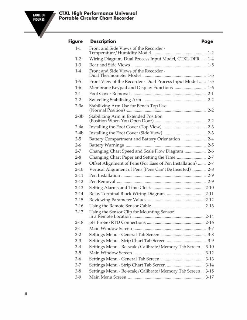
Figure Description Page 1-1 Front and Side Views of the Recorder - Temperature/Humidity Model ................................................ 1-2 1-2 Wiring Diagram, Dual Process Input Model, CTXL-DPR .... 1-4 1-3 Rear and Side Views ................................................................... 1-5 1-4 Front and Side Views of the Recorder - Dual Thermometer Model ......................................................... 1-5 1-5 Front View of the Recorder - Dual Process Input Model ...... 1-5 1-6 Membrane Keypad and Display Functions ............................ 1-6 2-1 Foot Cover Removal ................................................................... 2-1 2-2 Swiveling Stabilizing Arm ......................................................... 2-2 2-3a Stabilizing Arm Use for Bench Top Use (Normal Position) ....................................................................... 2-2 2-3b Stabilizing Arm in Extended Position (Position When You Open Door) .............................................. 2-2 2-4a Installing the Foot Cover (Top View) ...................................... 2-3 2-4b Installing the Foot Cover (Side View) ...................................... 2-3 2-5 Battery Compartment and Battery Orientation ...................... 2-4 2-6 Battery Warnings ........................................................................ 2-5 2-7 Changing Chart Speed and Scale Flow Diagram ................... 2-6 2-8 Changing Chart Paper and Setting the Time .......................... 2-7 2-9 Offset Alignment of Pens (For Ease of Pen Installation) ....... 2-7 2-10 Vertical Alignment of Pens (Pens Can’t Be Inserted) ............ 2-8 2-11 Pen Installation ............................................................................ 2-9 2-12 Pen Removal ................................................................................ 2-9 2-13 Setting Alarms and Time Clock .............................................. 2-10 2-14 Relay Terminal Block Wiring Diagram ................................. 2-11 2-15 Reviewing Parameter Values .................................................. 2-12 2-16 Using the Remote Sensor Cable .............................................. 2-13 2-17 Using the Sensor Clip for Mounting Sensor in a Remote Location ................................................................ 2-14 2-18 pH Probe/RTD Connections ................................................... 2-16 3-1 Main Window Screen ................................................................. 3-7 3-2 Settings Menu - General Tab Screen ........................................ 3-8 3-3 Settings Menu - Strip Chart Tab Screen ................................... 3-9 3-4 Settings Menu - Re-scale/Calibrate/Memory Tab Screen .. 3-10 3-5 Main Window Screen ............................................................... 3-12 3-6 Settings Menu - General Tab Screen ...................................... 3-13 3-7 Settings Menu - Strip Chart Tab Screen ................................. 3-14 3-8 Settings Menu - Re-scale/Calibrate/Memory Tab Screen .. 3-15 3-9 Main Menu Screen .................................................................... 3-17

iii
CTXL High Performance UniversalPortable Circular Chart Recorder
3-10 Settings Menu - General Tab Screen ...................................... 3-18 3-11 Settings Menu (Strip Chart Tab0 Screen ................................ 3-19 3-12 Settings Menu (Re-scale/Calibrate/Memory Tab) Screen .. 3-20 3-13 Typical Data File Screen ........................................................... 3-21 3-14 Main Menu Screen .................................................................... 3-23 3-15 Settings Menu - General Tab Screen ...................................... 3-24 3-16 Settings Menu (Strip Chart Tab) Screen ................................ 3-25 3-17 Settings Menu (Re-scale/Calibrate/Memory Tab) Screen . 3-26 4-1 Using Internal Excitation to Power External Transmitters (CTXL-DPR) ................................................................................. 4-5 8-1 Temperature/Humidity Wireless Transmitter, General
Dimensions, Labels and Descriptions ... 8-2 8-2 Battery Location in the Wireless Transmitter ......................... 8-2 8-3 Temperature/Humidity Wireless Receiver, General
Dimensions, Labels and Descriptions ... 8-3 8-4 Mounting Bracket Plate General Dimensions ......................... 8-3 8-5 Wireless Transmitter Mounting Bracket Assembly ............... 8-4 8-6 Wireless Transmitter Mounting Bracket Assembly For
Tripod Assembly ...................................... 8-4 8-7 Transmitter Mounting Bracket With DIN Rail Mount .......... 8-4 8-8 Wireless Transmitter, Main Menu ............................................ 8-5 8-9 Wireless Receiver, Main Menu ................................................. 8-6 8-10 Settings Menu - Transmitter/Receiver .................................... 8-7

iv
CTXL High Performance UniversalPortable Circular Chart Recorder
CAUTION & SAFETY INFORMATIONIf the equipment is used in a manner not specified in this manual, the protection provided by the equipment may be impaired.The Installation category is one (1).There is no user replaceable fuse in this product.The output terminals of this product are for use with equipment (digital meters, chart recorders, etc.) which have no accessible live parts. Such equipment should comply with all the applicable safety requirements.Do not operate the equipment in flammable or explosive environments.Power must be disconnected before making any electrical connections.A recommended DC adaptor is included with this product, 9 Vdc @ 1.7 A.
SAFETY WARNINGS AND IEC SYMBOLSThis device is marked with international safety and hazardous symbols in accordance with IEC1010. It is important to read and follow all the precautions and instructions in this manual before operating or commissioning this device as it contains important information relating to safety and EMC. Failure to follow all the safety precautions may result in injury and/or damage to your equipment.IEC Symbol Description
Caution - Refer to the accompanying document(s).
Direct Current

�1-1
Introduction1
This advanced Universal Circular Chart SUPERECORDER™ monitors and records data on a 1, 7, or 32 Days chart. The microprocessor based portable recorder provides many powerful and practical features as follows:• Four models are offered:
Temperature/Relative Humidity –TRH [-17 to 49ºC (2 to 120ºF) & 2 to 98% RH] Dual Thermocouple Input –DTC [ J , K , or T type TC ] Dual Process Input –DPR [ (0-1, 0-5, 0-10) VDC, (0-20, 4-20) mA ] pH and RTD Input - pH
• 203 mm (8") Chart paper for 1, 7, or 32 Day recording• Custom backlit LCD display shows two channels simultaneously• Membrane keypad provides full access to all functions of the recorder• Minimum, Maximum, and Average values are monitored and can be displayed• Chart data is stored in non-volatile memory• Chart paper can be re-scaled from the PC via RS232 interface• Temp/RH sensor probe can be up to 12.2 m (40 feet) away from the recorder without any sacrifice in performance• Universal Female Thermocouple Connector accepts either a sub-miniature or
standard male connector as inputs.• Battery as well as ac power operation.• Battery icon displays the status of the battery voltage• High & Low alarm points set via keypad• Audible & visual alarms with built-in Relay contacts• Additional two drive lines to power external Relays• Wall Mount or Bench top Mount• Built-in Real time Clock to monitor two channels vs. time• Electronic Lock/Unlock key for unauthorized access• RS232 Computer interface allows downloading of recorded chart data to PC• Recorder comes with two built-in chart lights, and time reference arrow• Decorative Foot cover for wall mounting• Double sided Linear Radial Chart Paper

1.1 Parts of the Recorder
M4098-F1-1.eps
H 35 T 2
T E M P E R A T U R E
H U M I D I T Y
1
11
5
11
2
21 22
4
9
2
8 13
10
7
6 9V 1A
12
14
13
°C °F SCALE
CLOCK SPEED SET LIGHT NO
DISPLAY
POWER
CHART ALARM
CONFIG YES MODE
°C °F SCALE
CLOCK SPEED SET LIGHT NO
DISPLAY
POWER
CHART ALARM
CONFIG YES MODE
PRINTED PANEL WHITE, PMS 427, PMS 430
°F RH % 7D
Figure 1-1. Front and Side Views of the Recorder - Temperature/Humidity Model
Item Description Function
1 Chart Paper Knob (magnetic) Holds chart paper in place.
2 Chart Lights Lights up the chart paper. The light comes on for 3 seconds in battery mode and permanently in ac adapter mode.
4 Time Reference Arrow Helps align the time on the new chart paper with the actual time.
5 Chart Paper Linear Radial Double sided charts are available for 1, 7, and 32 day recording. See the inside back cover for a detailed list of paper available.
Introduction1
�1-2
FRONT VIEW SIDE VIEW

Item Description Function 6 ac Power Jack Allows the unit to be powered from ac power using the universal
100/240 Vac adapter supplied.
7 Membrane Keypad Provides full access to all functions of the recorder.
8 Backlit LCD Display Displays temperature and relative humidity values simultaneously.
9 Temperature/Humidity Sensor Houses the electronic sensor which measures ambient temperature and relative humidity (CTXL-TRH only).
10 Sensor Holder (clip) Holds the temperature/humidity probe to the side of the recorder (CTXL-TRH only).
11 Pen Arm and Holder (2 each) Holds and moves the temperature and humidity pens. Upper pen, Temperature or Channel 1 Lower pen, Humidity or Channel 2
12 Latch Button Releases and secures the recorder’s door.
13 Decorative Foot Cover Stays in place for wall-mounting the recorder. The cover must be removed for upright bench-top use (otherwise the recorder topples over)!
14 Door Key It locks/unlocks the chart door.
15 “Keyhole” Slot Mounting Holes Allows the recorder to be mounted on the wall.
16 Carrying Slot Allows the user to carry the recorder conveniently.
17 Product Label Product information label.
18 Alarm/Relay Terminal Block Allows the user to connect to built-in relay contacts or power external mechanical relays.
19 Battery Compartment Holds 4 “D” size batteries which provide power if the ac adapter is not used, or provide power backup in case of ac power failure.
20 RS232 Connection Serial PC interface
21 Recorder Door It contains pen drive mechanisms. Open the door to change chart paper.
22 Ferrite Core Attach the snap-on Ferrite Core (included) on the Sensor Probe cable to minimize RF radiation emission.
23 Thermocouples Beaded Thermocouples with Mini-Spool Cappies.
24 Universal TC Connector (2 each) Allows thermocouple probes to be connected through a sub-mini or standard TC connector for Channel 1 and Channel 2 inputs
25 Cable with Stripped Leads Cable for Channel 1 and Channel 2 process input connections
26 Process Input Connectors 6 Pin Mini DIN Connector for voltage current input
Introduction 1
�1-3

Figure 1-2. Wiring Diagram, Dual Process Input Model, CTXL-DPR
Introduction1
�1-4
TORECORDER
PINS 3, 4, 6 ARE TIEDTOGETHER INTERNALLYTO COMMON GROUND
MINI-DINCONNECTOR
132 BROWN
15 VDC @ 50mAEXCITATION(INTERNAL)
GREEN
+
+
+
RED
BLK
PROCESSINPUT #1
–
–
–
654
ORANGE
YELLOW
PROCESSINPUT #2

°C °F SCALE
CLOCK SPEED SET LIGHT NO
DISPLAY
POWER
CHART ALARM
CONFIG YES MODE
°F
7D
°C °F SCALE
CLOCK SPEED SET LIGHT NO
DISPLAY
POWER
CHART ALARM
CONFIG YES MODE %
%
7D
°F
19
9V 1A
SEE WIRING DIAGRAM ON FIG. 1-2
VOLTAGE CURRENT
SENSOR/ PROCESS
INPUT
SENSOR/ PROCESS
INPUT
– +
20
23
24
25
26
15
16
18 10
1
17
17
H 35 T 2
CHAN 1
CHAN 2
INPUT TC
REAR AND SIDE VIEWS
Foot Cover Removed
FRONT AND SIDE VIEW OF RECORDER - DUAL THERMOCOUPLE MODEL
FRONT VIEW OF RECORDER - DUAL PROCESS INPUT MODEL
M4098-F1-2.eps
SEE PAGE 1-3 FOR DIAGRAM KEY
21
Figure 1-3. Rear and Side Views
Figure 1-4. Front and Side Views of the Recorder - Dual Thermocouple Model
Figure 1-5. Front View of the Recorder - Dual Process Input Model
Introduction 1
�1-5
REAR VIEW SIDE VIEW
°C °F SCALE
CLOCK SPEED SET LIGHT NO
DISPLAY
POWER
CHART ALARM
CONFIG YES MODE
°F
7D
°C °F SCALE
CLOCK SPEED SET LIGHT NO
DISPLAY
POWER
CHART ALARM
CONFIG YES MODE %
%
7D
°F
19
9V 1A
SEE WIRING DIAGRAM ON FIG. 1-2
VOLTAGE CURRENT
SENSOR/ PROCESS
INPUT
SENSOR/ PROCESS
INPUT
– +
20
23
24
25
26
15
16
18 10
1
17
17
H 35 T 2
CHAN 1
CHAN 2
INPUT TC
REAR AND SIDE VIEWS
Foot Cover Removed
FRONT AND SIDE VIEW OF RECORDER - DUAL THERMOCOUPLE MODEL
FRONT VIEW OF RECORDER - DUAL PROCESS INPUT MODEL
M4098-F1-2.eps
SEE PAGE 1-3 FOR DIAGRAM KEY
21
°C °F SCALE
CLOCK SPEED SET LIGHT NO
DISPLAY
POWER
CHART ALARM
CONFIG YES MODE
°F
7D
°C °F SCALE
CLOCK SPEED SET LIGHT NO
DISPLAY
POWER
CHART ALARM
CONFIG YES MODE %
%
7D
°F
19
9V 1A
SEE WIRING DIAGRAM ON FIG. 1-2
VOLTAGE CURRENT
SENSOR/ PROCESS
INPUT
SENSOR/ PROCESS
INPUT
– +
20
23
24
25
26
15
16
18 10
1
17
17
H 35 T 2
CHAN 1
CHAN 2
INPUT TC
REAR AND SIDE VIEWS
Foot Cover Removed
FRONT AND SIDE VIEW OF RECORDER - DUAL THERMOCOUPLE MODEL
FRONT VIEW OF RECORDER - DUAL PROCESS INPUT MODEL
M4098-F1-2.eps
SEE PAGE 1-3 FOR DIAGRAM KEY
21
Introduction1
�1-6
R
MIN
HAL1 2
MAX
LAL COM
AVG
°C°F
°C°FT1-T2
32D
7D
1D
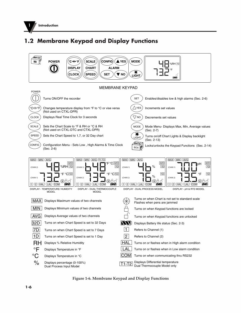
Turns ON/OFF the recorder
POWER
°C °F Changes temperature display from °F to °C or vise versa(Not used on CTXL-DPR)
SPEED Sets the Chart Speed to 1,7, or 32 Day chart
CLOCK Displays Real Time Clock for 3 seconds
SCALE Sets the Chart Scale to °F & RH or °C & RH(Not used on CTXL-DTC and CTXL-DPR)
CONFIG Configuration Menu - Sets Low , High Alarms & Time Clock(Sec. 2-6)
SET Enables/disables low & high alarms (Sec. 2-6)
YES Increments set values
NO Decrements set values
MODE Mode Menu- Displays Max, Min, Average values(Sec. 2-7)
LIGHT Turns on/off Chart Lights & Display backlight(Sec. 2-13)
Locks/unlocks the Keypad Functions (Sec. 2-14)
MEMBRANE KEYPAD
MAX Displays Maximum values of two channels
MIN Displays Minimum values of two channels
AVG Displays Average values of two channels
32D Turns on when Chart Speed is set to 32 Days
7D1D
Turns on when Chart Speed is set to 7 Days
Turns on when Chart Speed is set to 1 Day
RH
%
°F°C
Displays % Relative Humidity
Displays Temperature in °F
Displays Temperature in °C
Displays percentage (0-100%)Dual Process Input Model
Turns on when Chart is not set to standard scaleFlashes when pens are jammed
Turns on when Keypad functions are locked
Turns on when Keypad functions are unlocked
Displays Battery life status (Sec. 2-3)
1 Refers to Channel (1)
2 Refers to Channel (2)
HAL Turns on or flashes when in High alarm condition
LAL Turns on or flashes when in Low alarm condition
COM
T1-T2
Turns on when communicating thru RS232
Displays Differential temperatureDual Thermocouple Model only
DISPLAY - DUAL THERMOCOUPLEMODEL
MIN
HAL1 2
MAX
LAL COM
AVG
°F
pH 32D
7D
1D
DISPLAY - pH & RTD MODEL
MIN
HAL1 2
MAX
LAL COM
AVG
%
%
32D
7D
1D
DISPLAY - DUAL PROCESS MODEL
MIN
HAL1 2
MAX
LAL COM
AVG
°C°F
RH%32D
7D
1D
DISPLAY - TEMPERATURE/ HUMIDITYMODEL
°C °F SCALE
CLOCK SPEED SET LIGHTNO
DISPLAY
POWER
CHART ALARM
CONFIG YES MODE
°F
RH% 7D
(CHAN 1)
(CHAN 2)
(CHAN 1)
(CHAN 2)
(CHAN 1)
(CHAN 2)
(CHAN 2)
(CHAN 1)
1.2 Membrane Keypad and Display Functions
Figure 1-6. Membrane Keypad and Display Functions

�2-1
Setting Up the Recorder2
2.1 Placing the Recorder on the Bench TopFigure 2-1 shows the removal of the decorative foot cover.1. Place the recorder on its back (so it is face up).
2. Remove the clip-on foot cover by lifting up on the cover and releasing it from the stabilizing arm at the bottom of the recorder. This exposes the rubber feet and stabilizing arm. The rubber feet protect the bench top surface.
CAUTION
DO NOT ATTEMPT TO SET THE RECORDER UPRIGHT ON THE BENCH WHEN THE CLIP-ON FOOT COVER IS IN PLACE. THE RECORDER WILL TOPPLE OVER.
Clip
Cutaway View
M4098-F2-1.eps
Figure 2-1. Foot Cover Removal
!

3. Swing out the stabilizing arm and extend it towards you. Figure 2-2 shows how to swing out the stabilizing arm. Make sure the slot in the stabilizing arm extends out the rear of the recorder.
Swing
TEMPERATURE
HUMIDITY
HO TO
M4098-F2-2.eps
°C °F SCALE
CLOCK SPEED SET LIGHTNO
DISPLAY
POWER
CHART ALARM
CONFIG YES MODE
°C °F SCALE
CLOCK SPEED SET
LIGHTNO
DISPLAY
POWER
CHARTALARM
CONFIG YES MODE
Figure 2-2. Swiveling Stabilizing Arm
NOTE
When the recorder is in normal operating position (chart door is closed), the stabilizing arm should be pushed to middle position (the bumps on the arm will click in place under the recorder). Refer to Figure 2-3a.
Before opening the chart door, pull the stabilizing arm out to its full extension position to provide full stability. Refer to Figure 2-3b. After closing the door, return the arm to its middle position. Refer to Figure 2-3a.
Note that the arm extends towards the front or rear of the case. If the unit is placed on a bench top snug against the wall, extend the stabilizing arm fully to the front of the unit. Refer to Figure 2-3b.
TEMPERATURE
HUMIDITY
HO TO
M4098-F2-3a.eps
°C °F SCALE
CLOCK SPEED SET
LIGHTNO
DISPLAY
PO� ER
CHARTALARM
CONFIG YES MODE
TEMPERATURE
HUMIDITY
HO TO
M4098-F2-3b.eps
°C °F SCALE
CLOCK SPEED SET
LIGHTNO
DISPLAY
PO� ER
CHARTALARM
CONFIG YES MODE
Figure 2-3a. Stabilizing Arm Use Figure 2-3b. Stabilizing Arm in Extended for Bench Top Use (Normal Position) Position (Position When You Open Door)
Setting Up the Recorder2
�2-2
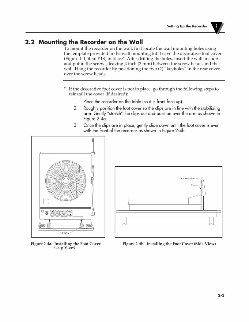
2.2 Mounting the Recorder on the WallTo mount the recorder on the wall, first locate the wall mounting holes using the template provided in the wall mounting kit. Leave the decorative foot cover (Figure 1-1, item #18) in place*. After drilling the holes, insert the wall anchors and put in the screws, leaving 1⁄8 inch (3 mm) between the screw heads and the wall. Hang the recorder by positioning the two (2) “keyholes” in the rear cover over the screw heads.
* If the decorative foot cover is not in place, go through the following steps to reinstall the cover (if desired):
1. Place the recorder on the table (so it is front face up). 2. Roughly position the foot cover so the clips are in line with the stabilizing
arm. Gently “stretch” the clips out and position over the arm as shown in Figure 2-4a.
3. Once the clips are in place, gently slide down until the foot cover is even with the front of the recorder as shown in Figure 2-4b.
Clips
H35 T2
TEMPERATURE
HUMIDITY
M4098-F2-4a.eps
°C °F SCALE
CLOCK SPEED SET LIGHTNO
DISPLAY
POWER
CHART ALARM
CONFIG YES MODE
Clip
Cutaway View
M4098-F2-4b.eps
Figure 2-4a. Installing the Foot Cover Figure 2-4b. Installing the Foot Cover (Side View) (Top View)
Setting Up the Recorder 2
�2-3

2.3 Using BatteriesThe recorder operates on either four “D” size non-rechargeable alkaline batteries or a universal (100-240 Vac, 50-60 Hz) ac adapter.
NOTE
In the event of ac power failure, the unit will switch over to battery power automatically. Keep a fresh set of batteries in the unit in case of power outage.
2.3.1 Installing BatteriesYou may power the recorder with four “D” size alkaline batteries. Under normal conditions, the recorder operates full time on battery power for up to three months when using fresh alkaline batteries. When replacing batteries, we recommend that you use Alkaline “D” size batteries for long life and for best performance at low temperatures.To install the batteries (refer to Figure 2-5):
Press Down To Open Battery Door
Battery Orientation
+ – + – + – + –
M4098-F2-5.eps
Figure 2-5. Battery Compartment and Battery Orientation
Setting Up the Recorder2
�2-4

The battery icon on the LCD shows the status of the batteries as shown below.
M4098-BatteryIcons.eps
Full Battery Life (100%)
75% Battery Life
50% Battery Life
25% Battery Life
Low Battery - Replace Battery
No Battery Icon – AC adapter
Figure 2-6. Battery Warnings
2.3.2 Connecting ac PowerThe recorder can be ac powered using the universal 100-240 Vac adapter supplied. The dc power jack is located on the right side of the unit (refer to Figure 1-1, item #6.). The ac adapter provides 9 Vdc @ 1.7A power output and comes with a 1.8 meters (6 ft.) long cable.
The following parameters are stored in the non-volatile memory and will not be lost when batteries or main power are removed • Chart speed & scale • High & low alarm set points for the two channel • Chart Data points
When the recorder runs only on AC adaptor, and the main power restores after a power failure, the recorder turns on automatically without pressing the Power Key. All LCD segments turn on momentarily, then there is a 20 second delay before the revision screen. This only happens when the power is removed without pressing the Power Key. The pens go to the home position and back to the correct chart scale everytime the recorder powers up.
Setting Up the Recorder 2
�2-5
NOTE
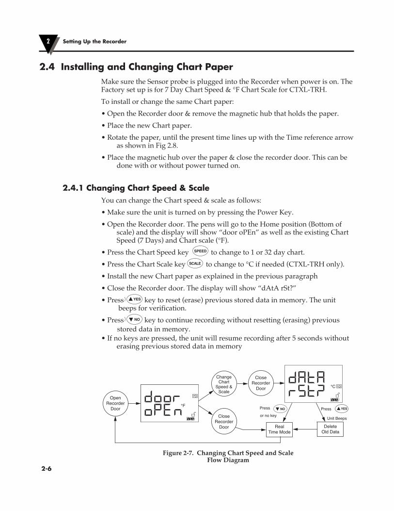
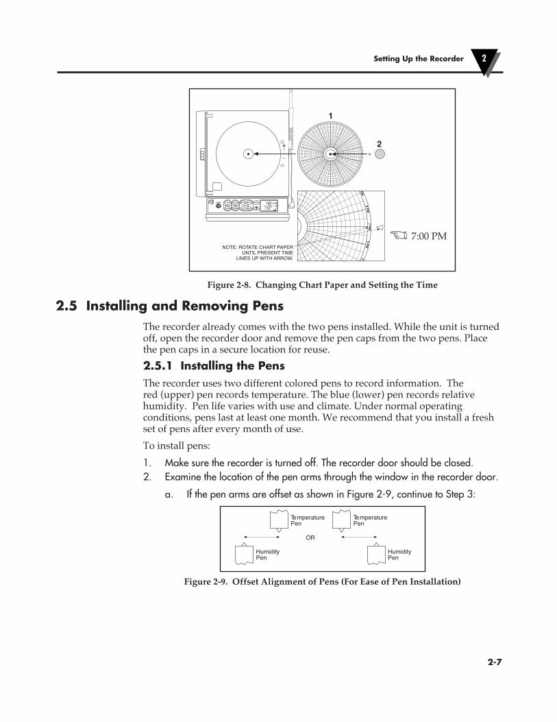
2.4 Installing and Changing Chart PaperMake sure the Sensor probe is plugged into the Recorder when power is on. The Factory set up is for 7 Day Chart Speed & °F Chart Scale for CTXL-TRH.To install or change the same Chart paper:• Open the Recorder door & remove the magnetic hub that holds the paper.• Place the new Chart paper.• Rotate the paper, until the present time lines up with the Time reference arrow
as shown in Fig 2.8.• Place the magnetic hub over the paper & close the recorder door. This can be
done with or without power turned on.
2.4.1 Changing Chart Speed & ScaleYou can change the Chart speed & scale as follows:• Make sure the unit is turned on by pressing the Power Key.• Open the Recorder door. The pens will go to the Home position (Bottom of
scale) and the display will show “door oPEn” as well as the existing Chart Speed (7 Days) and Chart scale (°F).
• Press the Chart Speed key
°C °F SCALE
CLOCK SPEED SET LIGHTNO
POWER CONFIG YES MODE
to change to 1 or 32 day chart.• Press the Chart Scale key°C °F SCALE
CLOCK SPEED SET LIGHTNO
POWER CONFIG YES MODE to change to °C if needed (CTXL-TRH only).• Install the new Chart paper as explained in the previous paragraph• Close the Recorder door. The display will show “dAtA rSt?”• Press °C °F SCALE
CLOCK SPEED SET LIGHTNO
POWER CONFIG YES MODE key to reset (erase) previous stored data in memory. The unit beeps for verification.
• Press
°C °F SCALE
CLOCK SPEED SET LIGHTNO
POWER CONFIG YES MODE
key to continue recording without resetting (erasing) previous stored data in memory.• If no keys are pressed, the unit will resume recording after 5 seconds without
erasing previous stored data in memory
°F
7D
°C 1D
OpenRecorder
DoorClose
RecorderDoor
CloseRecorder
Door
ChangeChart
Speed &Scale
DeleteOld Data
RealTime Mode
Press Press
Unit Beepsor no key
Figure 2-7 Changing Chart Speed & Scale Flow Chart
NO YES
Figure 2-7. Changing Chart Speed and ScaleFlow Diagram
Setting Up the Recorder2
�2-6
NOTE: ROTATE CHART PAPERUNTIL PRESENT TIME
LINES UP WITH ARROW.
H35 T2
1
2
°C °F SCALE
CLOCK SPEED SET LIGHTNO
DISPLAY
POWER
CHART ALARM
CONFIG YES MODE
°FRH% 7D
1D
M4098-F2-8.eps
7 PM8 PM
9 PM
6 PM5 P
Figure 2-8. Changing Chart Paper and Setting the Time
2.5 Installing and Removing PensThe recorder already comes with the two pens installed. While the unit is turned off, open the recorder door and remove the pen caps from the two pens. Place the pen caps in a secure location for reuse.2.5.1 Installing the PensThe recorder uses two different colored pens to record information. The red (upper) pen records temperature. The blue (lower) pen records relative humidity. Pen life varies with use and climate. Under normal operating conditions, pens last at least one month. We recommend that you install a fresh set of pens after every month of use.To install pens:1. Make sure the recorder is turned off. The recorder door should be closed.2. Examine the location of the pen arms through the window in the recorder door.
a. If the pen arms are offset as shown in Figure 2-9, continue to Step 3:
M4098-F2-9
OR
TemperaturePen
TemperaturePen
HumidityPen
HumidityPen
Figure 2-9. Offset Alignment of Pens (For Ease of Pen Installation)
Setting Up the Recorder 2
�2-7
X 7:00 PM
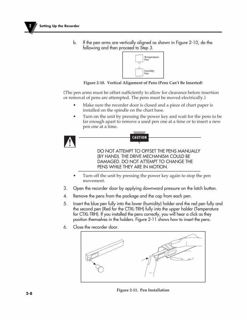
b. If the pen arms are vertically aligned as shown in Figure 2-10, do the following and then proceed to Step 3.
TemperaturePen
HumidityPen
M4098-F2-10
Figure 2-10. Vertical Alignment of Pens (Pens Can’t Be Inserted)
(The pen arms must be offset sufficiently to allow for clearance before insertion or removal of pens are attempted. The pens must be moved electrically.) • Make sure the recorder door is closed and a piece of chart paper is
installed on the spindle on the chart base. • Turn on the unit by pressing the power key and wait for the pens to be
far enough apart to remove a used pen one at a time or to insert a new pen one at a time.
CAUTION
DO NOT ATTEMPT TO OFFSET THE PENS MANUALLY (BY HAND). THE DRIVE MECHANISM COULD BE DAMAGED. DO NOT ATTEMPT TO CHANGE THE PENS WHILE THEY ARE IN MOTION.
• Turn off the unit by pressing the power key again to stop the pen movement.
3. Open the recorder door by applying downward pressure on the latch button.
4. Remove the pens from the package and the cap from each pen.
5. Insert the blue pen fully into the lower (humidity) holder and the red pen fully and the second pen (Red for the CTXL-TRH) fully into the upper holder (Temperature for CTXL-TRH). If you installed the pens correctly, you will hear a click as they position themselves in the holders. Figure 2-11 shows how to insert the pens.
6. Close the recorder door.
M4098-F2-12
Figure 2-11. Pen Installation
Setting Up the Recorder2
�2-8
!
2.5.2 Removing the Pens1. Check to see that the pens are offset as shown in Figure 2-9. Otherwise, you
can damage the arm and drive mechanism if you try to remove them.
CAUTION
DO NOT ATTEMPT TO OFFSET THE PENS MANUALLY (BY HAND). THE DRIVE MECHANISM COULD BE DAMAGED. DO NOT ATTEMPT TO CHANGE THE PENS WHILE THEY ARE IN MOTION.
2. Perform Step 2b in Section 2.5.1 to offset the pens.
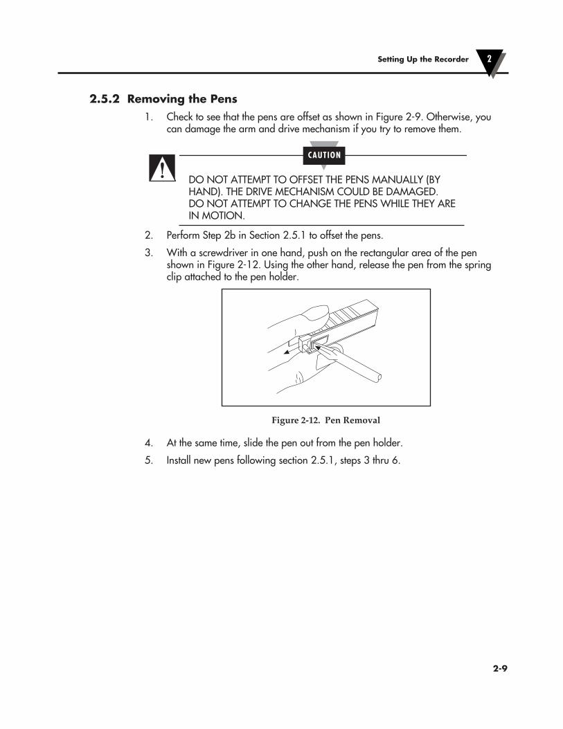
3. With a screwdriver in one hand, push on the rectangular area of the pen shown in Figure 2-12. Using the other hand, release the pen from the spring clip attached to the pen holder.
M4098-F2-13
Figure 2-12. Pen Removal
4. At the same time, slide the pen out from the pen holder.
5. Install new pens following section 2.5.1, steps 3 thru 6.
Setting Up the Recorder 2
�2-9
!

2.6 Setting Alarms and Time ClockThe following flow chart shows how to set the alarms and the time clock in a Temperature/Humidity model recorder.
Setting Up the Recorder2
�2-10
RH
°F
% 7D
1
°F
7D
1
°F
7D
Press or keys to set high alarm
Press key to enable/disable alarm
7DRH%
2
High Alarm - Channel 1 (Temperature)
Real Time Mode
Low Alarm - Channel 1 (Temperature)
Press or keys to set low alarm
Press key to enable/disable alarm
High Alarm - Channel 2 (Humidity)Press or keys to set high alarm
Press key to enable/disable alarm
2
RH% 7D
Press key to enable/disable alarm
Low Alarm - Channel 2 (Humidity)Press or keys to set low alarm
7D
7D
HAL icon is on when high alarm enabled
icon is on when low alarm enabledLAL
HAL
LAL icon is on when low alarm enabled
(Military time 0-23)
Clock - Display HourPress or keys to set the hour
icon is on when high alarm enabled
CONFIG
CONFIG
CONFIG
CONFIG
CONFIG
CONFIG
(00-59)
Clock - Display MinutePress or keys to set the minute
MODE
MODE
MODE
MODE
MODE
MODE
7D
CONFIG
(1-12)
Clock - Display MonthPress or keys to set the month
MODE
7D
CONFIG
CONFIG
(01-31)
Clock - Display DayPress or keys to set the day
HAL
LAL
HAL
LAL
SET
SET
SET
SET
NO
NO
YES
YES
NOYES
NOYES
NOYES
NOYES
NOYES
NOYES
Figure 2-13. Setting Alarms and Time Clock
Press °C °F SCALE
CLOCK SPEED SET LIGHTNO
POWER CONFIG YES MODE key to get into the Configuration mode. In this mode, you can set High & Low alarm points as well as the Time Clock as shown in the flow chart on the previous page.You can exit the configuration menu at any time by pressing the °C °F SCALE
CLOCK SPEED SET LIGHTNO
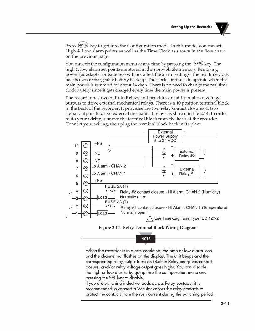
POWER CONFIG YES MODE key. The high & low alarm set points are stored in the non-volatile memory. Removing power (ac adapter or batteries) will not affect the alarm settings. The real time clock has its own rechargeable battery back up. The clock continues to operate when the main power is removed for about 14 days. There is no need to change the real time clock battery since it gets charged every time the main power is present.The recorder has two built-in Relays and provides an additional two voltage outputs to drive external mechanical relays. There is a 10 position terminal block in the back of the recorder. It provides the two relay contact closures & two signal outputs to drive external mechanical relays as shown in Fig 2.14. In order to do your wiring, remove the terminal block from the back of the recorder. Connect your wiring, then plug the terminal block back in its place.
71
2
4
3
6
5
7
8
9
10
NC
–PS
+PSFUSE 2A (T)
FUSE 2A (T)
Lo Alarm - CHAN 2
Lo Alarm - CHAN 1
NC
ExternalPower Supply5 to 24 VDC
+
+
+
–
–
–
Relay #2 contact closure - Hi Alarm, CHAN 2 (Humidity) Normally open
Relay #1 contact closure - Hi Alarm, CHAN 1 (Temperature)Normally open
Use Time-Lag Fuse Type IEC 127-2
FIG 2-14 Terminal Block Wiring Diagram
ExternalRelay #1
ExternalRelay #2
Load
Load
Figure 2-14. Relay Terminal Block Wiring Diagram
When the recorder is in alarm condition, the high or low alarm icon and the channel no. flashes on the display. The unit beeps and the corresponding relay output turns on (Built-in Relay energizes-contact closure- and/or relay voltage output goes high). You can disable the high or low alarms by going thru the configuration menu and pressing the SET key to disable. If you are switching inductive loads across Relay contacts, it is recommended to connect a Varistor across the relay contacts to protect the contacts from the rush current during the switching period.
Setting Up the Recorder 2
�2-11
NOTE

2.7 Reviewing Parameter Values
You can review the Maximum, Minimum, and Average values of the two channels by pressing the °C °F SCALE
CLOCK SPEED SET LIGHTNO
POWER CONFIG YES MODE key. You can review the differential temperature between the two channels (T1-T2) on the Dual Thermocouple models. You can reset the values and start fresh at any time by pressing the
°C °F SCALE
CLOCK SPEED SET LIGHTNO
POWER CONFIG YES MODE
key.
Figure 2-15. Reviewing Parameter Values
NOTE
The Minimum, Maximum, and Average values will reset when power is removed.
Setting Up the Recorder2
�2-12
%
%7D
Real Time Mode
MAX
2.7 Reviewing Parameter values
MAX
%
%7D
MIN
%
%7D
AVG
%
%7D
You can review the Maximum, Minimum, and Average temperature &relative humidity values by pressing the key. You can reset thevalues and start fresh at any time by pressing the key.
MIN
icon is on. Display AverageProcess valuesPress key to reset all values
AVG
MODE
MODE
MODE
MODE
MODE
SET
SET
SET
SET
RH
°F
% 7D
Real Time Mode
MAXMAX
RH
°F
% 7D
MIN
°F
RH% 7D
AVG
RH%
°F
7D
MIN
icon is on. Display AverageTemperature and RelativeHumidity values Press key to resetall values
AVG
MODE
MODE
MODE
MODE
SET
SET
SET
°F
°F7D
Real Time Mode
MAXMAX
°F
°F7D
MIN
°F
°F7D
AVG
°F
°F7D
icon is on. Display Minimum Temperature valuesPress key to reset all values
MIN
icon is on. Display Average Temperature valuesPress key to reset all values
AVG
MODE
MODE
MODE
SET
SET
SET
T1-T2°F
7D icon is on. Display Differential Temperature valuesPress key to reset all values
T1-T2MODE
MODE
SET
icon is on. Display MaximumProcess valuesPress key to reset all values
icon is on. Display MaximumTemperature valuesPress key to reset all values
icon is on. Display MinimumProcess valuesPress key to reset all values
icon is on. Display MaximumTemperature and RelativeHumidity valuesPress key to resetall values
icon is on. Display MinimumTemperature and RelativeHumidity valuesPress key to resetall values
Temperature/Humidity Model Dual Process Model Dual Thermocouple Model
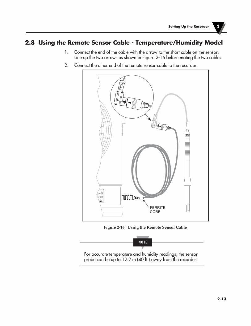
2.8 Using the Remote Sensor Cable - Temperature/Humidity Model1. Connect the end of the cable with the arrow to the short cable on the sensor.
Line up the two arrows as shown in Figure 2-16 before mating the two cables.
2. Connect the other end of the remote sensor cable to the recorder.
M4098-F2-16.eps
H35 T2 H35 T2
TEMPERATURE
OM
°C°F
RH%32D7D
1D
FERRITECORE
Figure 2-16. Using the Remote Sensor Cable
NOTE
For accurate temperature and humidity readings, the sensor probe can be up to 12.2 m (40 ft.) away from the recorder.
Setting Up the Recorder 2
�2-13
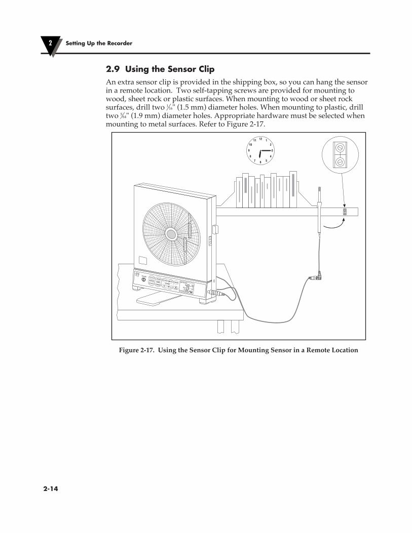
2.9 Using the Sensor ClipAn extra sensor clip is provided in the shipping box, so you can hang the sensor in a remote location. Two self-tapping screws are provided for mounting to wood, sheet rock or plastic surfaces. When mounting to wood or sheet rock surfaces, drill two 1⁄16" (1.5 mm) diameter holes. When mounting to plastic, drill two 5⁄64" (1.9 mm) diameter holes. Appropriate hardware must be selected when mounting to metal surfaces. Refer to Figure 2-17.
M4098-F2-17.eps
TEMPERATURE
HUMIDITY
678
9
54
3
2112
1011
°C °� �CA�E
C��C� �PEED �ET�I�HT
��
DI�P�AY
P�� ER
CHARTA�ARM
C���I� YE� M�DE MIN
HAL1 2
MAX
LAL COM
AVG
°C°F
RH%32D7D
1D
Figure 2-17. Using the Sensor Clip for Mounting Sensor in a Remote Location
Setting Up the Recorder2
�2-14

2.10 Open/Out of Range InputIf the input to the recorder is open or out of range, the chart motor continues to run but the recorder handles the situation as follows:1. Temperature/Humidity Model: When the sensor probe is disconnected, the
pens go to the home position and the display shows “Prb Err”. When the probe is out of range, the display flashes.
2. Dual Thermocouple Model: When any of the two thermocouple inputs open up, the pens go to the home position, and the display shows “Prb Err”. When the input is out of range, the display flashes.
3. Dual Process input Model: When the two inputs are out of range, the display flashes.
2.11 Pen JammingEach pen drive mechanism has two optical sensors. One is to detect the home position, the other is to detect pen movement. If the pen drive mechanism skips steps due to wear & tear or dirt & dust over a period of time, the recorder can compensate for it so that the pens are at the right location on the chart. If the pens have too much friction or get jammed for any reason, the recorder detects the situation. It turns off both the pen and the chart motors. It continues to display the parameters on the LCD and stores data in the memory. The Chart icon starts to flash to indicate Pen Jamming.Once the pen drive mechanisms are serviced, and the recorder is powered back on, the unit continues to operate normally and the chart icon flashing will disappear.
2.12 Pen Re-scalingEach or both pens can be re-scaled within the range of the input sensor. Here are the standard chart ranges for the three models:Temperature/ Humidity Model -17.7 to 49ºC (0 to 120ºF) 0 to 100% RHDual Thermocouple Input Type K -40 to 560ºC (-40 to 1040ºF) Type J -40 to 260ºC (-40 to 500ºF) Type T -40 to 160ºC (-40 to 320ºF)Dual Process Input 0 to 100%The pens can be re-scaled thru RS232 from the PC using certain commands. See Chapter 3 for more details. Once the pens are re-scaled, the Chart icon turns on. The unit remembers the new pen scales even if the main power is removed. The chart icon will disappear if the pens are scaled back to factory settings.
Setting Up the Recorder 2
�2-15
pH PROBE
RTD
2.13 Chart Lights & Display Backlight
You can turn ON/OFF the chart lights and the display backlight by pressing the
R
MIN
HAL1 2
MAX
LAL COM
AVG
°C°F
°C°FT1-T2
32D
7D
1D
Turns ON/OFF the recorder
POWER
°C °F Changes temperature display from °F to °C or vise versa(Not used on CTXL-DPR)
SPEED Sets the Chart Speed to 1,7, or 32 Day chart
CLOCK Displays Real Time Clock for 3 seconds
SCALE Sets the Chart Scale to °F & RH or °C & RH(Not used on CTXL-DTC and CTXL-DPR)
CONFIG Configuration Menu - Sets Low , High Alarms & Time Clock(Sec. 2-6)
SET Enables/disables low & high alarms (Sec. 2-6)
YES Increments set values
NO Decrements set values
MODE Mode Menu- Displays Max, Min, Average values(Sec. 2-7)
LIGHT Turns on/off Chart Lights & Display backlight(Sec. 2-13)
Locks/unlocks the Keypad Functions (Sec. 2-14)
MEMBRANE KEYPAD
MAX Displays Maximum values of two channels
MIN Displays Minimum values of two channels
AVG Displays Average values of two channels
32D Turns on when Chart Speed is set to 32 Days
7D1D
Turns on when Chart Speed is set to 7 Days
Turns on when Chart Speed is set to 1 Day
RH
%
°F°C
Displays % Relative Humidity
Displays Temperature in °F
Displays Temperature in °C
Displays percentage (0-100%)Dual Process Input Model
Turns on when Chart is not set to standard scaleFlashes when pens are jammed
Turns on when Keypad functions are locked
Turns on when Keypad functions are unlocked
Displays Battery life status (Sec. 2-3)
1 Refers to Channel (1)
2 Refers to Channel (2)
HAL Turns on or flashes when in High alarm condition
LAL Turns on or flashes when in Low alarm condition
COM
T1-T2
Turns on when communicating thru RS232
Displays Differential temperatureDual Thermocouple Model only
DISPLAY - DUAL THERMOCOUPLEMODEL
MIN
HAL1 2
MAX
LAL COM
AVG
°F
pH 32D
7D
1D
DISPLAY - pH & RTD MODEL
MIN
HAL1 2
MAX
LAL COM
AVG
%
%
32D
7D
1D
DISPLAY - DUAL PROCESS MODEL
MIN
HAL1 2
MAX
LAL COM
AVG
°C°F
RH%32D
7D
1D
DISPLAY - TEMPERATURE/ HUMIDITYMODEL
°C °F SCALE
CLOCK SPEED SET LIGHTNO
DISPLAY
POWER
CHART ALARM
CONFIG YES MODE
°F
RH% 7D
(CHAN 1)
(CHAN 2)
(CHAN 1)
(CHAN 2)
(CHAN 1)
(CHAN 2)
(CHAN 2)
(CHAN 1)
key on the front panel keypad. In Battery mode (Battery Powered), the lights stay on for 3 seconds. In DC adaptor mode, the lights say on until pressing the
R
MIN
HAL1 2
MAX
LAL COM
AVG
°C°F
°C°FT1-T2
32D
7D
1D
Turns ON/OFF the recorder
POWER
°C °F Changes temperature display from °F to °C or vise versa(Not used on CTXL-DPR)
SPEED Sets the Chart Speed to 1,7, or 32 Day chart
CLOCK Displays Real Time Clock for 3 seconds
SCALE Sets the Chart Scale to °F & RH or °C & RH(Not used on CTXL-DTC and CTXL-DPR)
CONFIG Configuration Menu - Sets Low , High Alarms & Time Clock(Sec. 2-6)
SET Enables/disables low & high alarms (Sec. 2-6)
YES Increments set values
NO Decrements set values
MODE Mode Menu- Displays Max, Min, Average values(Sec. 2-7)
LIGHT Turns on/off Chart Lights & Display backlight(Sec. 2-13)
Locks/unlocks the Keypad Functions (Sec. 2-14)
MEMBRANE KEYPAD
MAX Displays Maximum values of two channels
MIN Displays Minimum values of two channels
AVG Displays Average values of two channels
32D Turns on when Chart Speed is set to 32 Days
7D1D
Turns on when Chart Speed is set to 7 Days
Turns on when Chart Speed is set to 1 Day
RH
%
°F°C
Displays % Relative Humidity
Displays Temperature in °F
Displays Temperature in °C
Displays percentage (0-100%)Dual Process Input Model
Turns on when Chart is not set to standard scaleFlashes when pens are jammed
Turns on when Keypad functions are locked
Turns on when Keypad functions are unlocked
Displays Battery life status (Sec. 2-3)
1 Refers to Channel (1)
2 Refers to Channel (2)
HAL Turns on or flashes when in High alarm condition
LAL Turns on or flashes when in Low alarm condition
COM
T1-T2
Turns on when communicating thru RS232
Displays Differential temperatureDual Thermocouple Model only
DISPLAY - DUAL THERMOCOUPLEMODEL
MIN
HAL1 2
MAX
LAL COM
AVG
°F
pH 32D
7D
1D
DISPLAY - pH & RTD MODEL
MIN
HAL1 2
MAX
LAL COM
AVG
%
%
32D
7D
1D
DISPLAY - DUAL PROCESS MODEL
MIN
HAL1 2
MAX
LAL COM
AVG
°C°F
RH%32D
7D
1D
DISPLAY - TEMPERATURE/ HUMIDITYMODEL
°C °F SCALE
CLOCK SPEED SET LIGHTNO
DISPLAY
POWER
CHART ALARM
CONFIG YES MODE
°F
RH% 7D
(CHAN 1)
(CHAN 2)
(CHAN 1)
(CHAN 2)
(CHAN 1)
(CHAN 2)
(CHAN 2)
(CHAN 1)
key again to turn them off.2.14 Lock/Unlock Keypad Functions (White Box)
You can Lock/Unlock the front panel keypad functions by pressing & holding the key for 3 seconds. When in lock mode, the lock icon comes on and the configuration menu will be inactive (Config, Set, Yes, No). When in unlock mode, the Unlock icon comes on and all the keys are active.
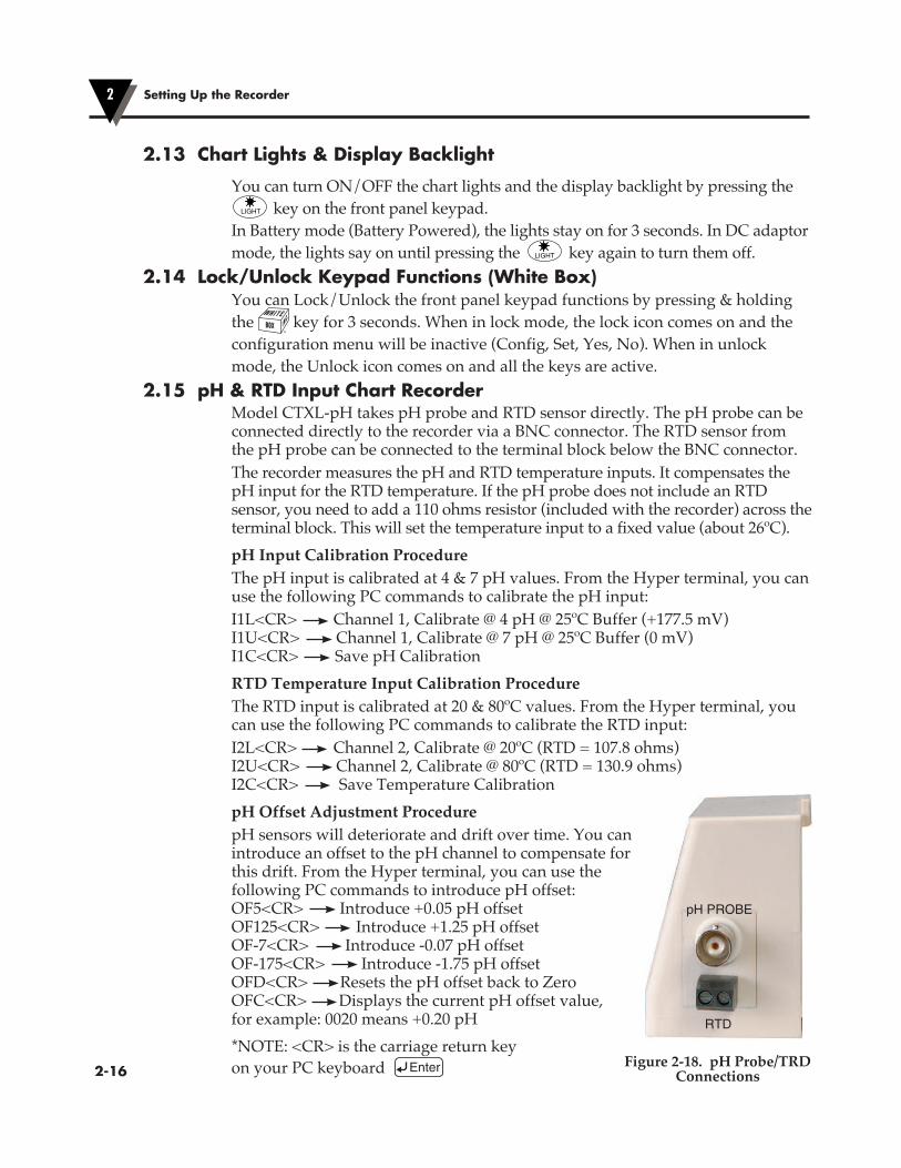
2.15 pH & RTD Input Chart RecorderModel CTXL-pH takes pH probe and RTD sensor directly. The pH probe can be connected directly to the recorder via a BNC connector. The RTD sensor from the pH probe can be connected to the terminal block below the BNC connector.The recorder measures the pH and RTD temperature inputs. It compensates the pH input for the RTD temperature. If the pH probe does not include an RTD sensor, you need to add a 110 ohms resistor (included with the recorder) across the terminal block. This will set the temperature input to a fixed value (about 26ºC).pH Input Calibration ProcedureThe pH input is calibrated at 4 & 7 pH values. From the Hyper terminal, you can use the following PC commands to calibrate the pH input:I1L<CR> Channel 1, Calibrate @ 4 pH @ 25ºC Buffer (+177.5 mV) I1U<CR> Channel 1, Calibrate @ 7 pH @ 25ºC Buffer (0 mV) I1C<CR> Save pH CalibrationRTD Temperature Input Calibration ProcedureThe RTD input is calibrated at 20 & 80ºC values. From the Hyper terminal, you can use the following PC commands to calibrate the RTD input:I2L<CR> Channel 2, Calibrate @ 20ºC (RTD = 107.8 ohms) I2U<CR> Channel 2, Calibrate @ 80ºC (RTD = 130.9 ohms) I2C<CR> Save Temperature CalibrationpH Offset Adjustment ProcedurepH sensors will deteriorate and drift over time. You can introduce an offset to the pH channel to compensate for this drift. From the Hyper terminal, you can use the following PC commands to introduce pH offset:OF5<CR> Introduce +0.05 pH offset OF125<CR> Introduce +1.25 pH offset OF-7<CR> Introduce -0.07 pH offset OF-175<CR> Introduce -1.75 pH offset OFD<CR> Resets the pH offset back to Zero OFC<CR> Displays the current pH offset value, for example: 0020 means +0.20 pH*NOTE: <CR> is the carriage return key on your PC keyboard Enter
Setting Up the Recorder2
�2-16Figure 2-18. pH Probe/TRD
Connections

�3-1
PC Interface Software3
3 PC CommunicationYou can communicate with the CTXL recorder thru RS232 port from a PC. There are a number of PC commands that allows the user to do the following functions:• Get the data (Like Temperature & Relative Humidity) in real time. This is the
same data displayed on the LCD.• Download the stored chart data from the recorder to the PC. It will save the
data into a data file. It can then be imported into the Excel spread sheet program for further review and analysis.
• Re-scale the Chart paper for one or both Pens to any range within the input operating range.
• Reset the Chart scale back to the Factory standard scales.You can initiate the PC commands from the Hyper terminal or can develop your own program and incorporate these commands. Here are the steps to work from the Hyper terminal:• From Start Programs Accessories Hyper Terminal• Create a name for your communication• Set the communication settings as follows (In the Properties Menu): - COM port (1, 2, 3) - Baud Rate (9600) - Data Bits (8) - Parity (None) - Stop Bit (1) - Flow Control (None)
3.1 Get Display Data in Real TimeYou can get the data for channels 1 & 2 in real time. It will be the same data displayed on the LCD. The following two commands perform such functions.In the Temperature/Humidity Model, the temperature data is multiplied by 10 using the AT command. Please note that all the PC commands terminate with a Carriage Return. In the Example section of the following tables, the PC commands are in Bold, and the response is in regular text.
Command Description Example
AT Get display data from Chan 1 (Temperature) AT;0748
AH Get display data from Chan 2 (Humidity) AH;0048
PC Interface Software3
�3-2
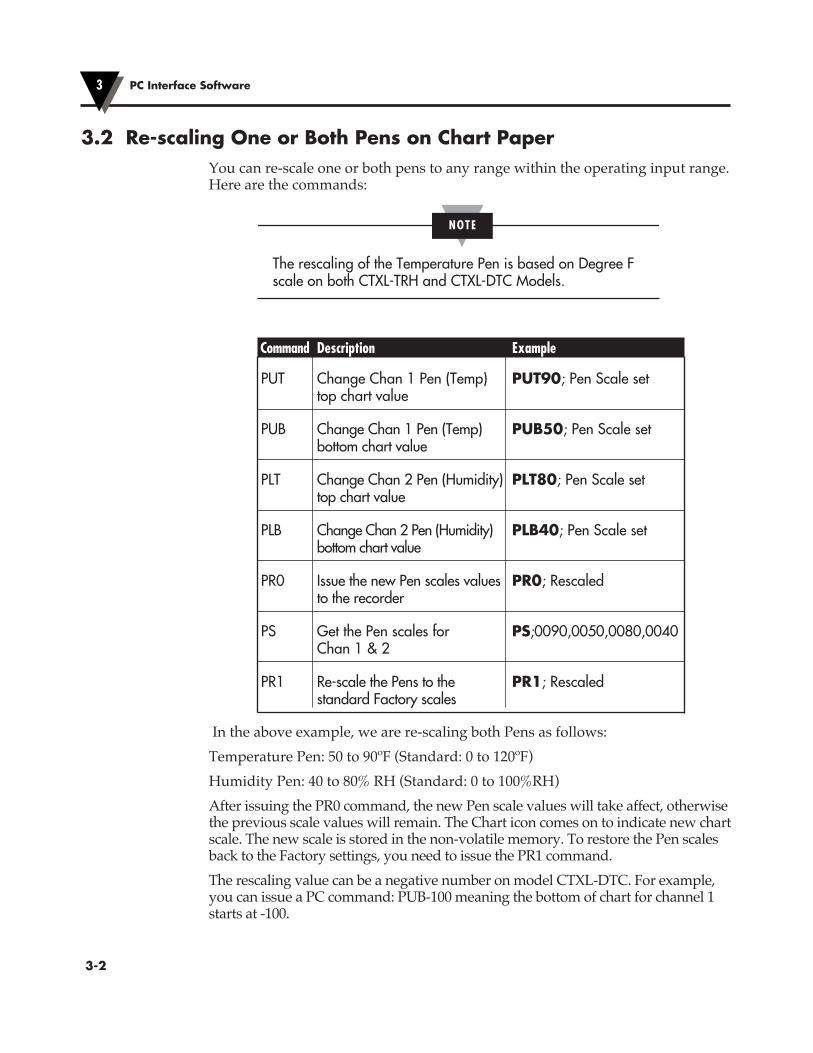
3.2 Re-scaling One or Both Pens on Chart PaperYou can re-scale one or both pens to any range within the operating input range. Here are the commands:
NOTE
The rescaling of the Temperature Pen is based on Degree F scale on both CTXL-TRH and CTXL-DTC Models.
Command Description Example
PUT Change Chan 1 Pen (Temp) PUT90; Pen Scale set top chart value
PUB Change Chan 1 Pen (Temp) PUB50; Pen Scale set bottom chart value
PLT Change Chan 2 Pen (Humidity) PLT80; Pen Scale set top chart value
PLB Change Chan 2 Pen (Humidity) PLB40; Pen Scale set bottom chart value
PR0 Issue the new Pen scales values PR0; Rescaled to the recorder
PS Get the Pen scales for PS;0090,0050,0080,0040 Chan 1 & 2
PR1 Re-scale the Pens to the PR1; Rescaled standard Factory scales
In the above example, we are re-scaling both Pens as follows:Temperature Pen: 50 to 90ºF (Standard: 0 to 120ºF)Humidity Pen: 40 to 80% RH (Standard: 0 to 100%RH)After issuing the PR0 command, the new Pen scale values will take affect, otherwise the previous scale values will remain. The Chart icon comes on to indicate new chart scale. The new scale is stored in the non-volatile memory. To restore the Pen scales back to the Factory settings, you need to issue the PR1 command.The rescaling value can be a negative number on model CTXL-DTC. For example, you can issue a PC command: PUB-100 meaning the bottom of chart for channel 1 starts at -100.

3
�3-3
PC Interface Software 3
3.3 Download Stored Chart Data from Recorder to PCYou need to create a Text file for saving the data from the recorder before issuing the MD command. While in Hyperterminal, go to: Transfer Capture Text (Create a Text file) Start
Command Description Example
MD Download stored Chart data & save it in a data file MD;
MI Erase stored Chart data from recorder’s memory MI;Done
When you issue the MD command, it will download the Chart data (Chan 1 & 2) stored in the non-volatile memory of the recorder. It will save the data into a text file which can be imported into the Excel spread sheet program. Depending on the amount of data stored in the non-volatile memory of the recorder, the data transfer could take up to 3 minutes.Here is a sample of data downloaded from the recorder.CTXL Circular Chart Recorder Ver: 10.12 OnLine Chart Speed: 1d Hum% Temp Deg F0012 00750011 00760012 00770013 00780014 00790014 00790015 00800017 00790020 0078 ,,Month, Day, Hour, Minute, ,,0012, 0019, 009, 0012 Ending TimePlease note that the data file begins with the Chart Speed (1, 7, 32 Days). Then it follows the headings of the data (Humidity % RH, Temp Deg F). Then it follows the chart data. Then the Ending Time of the Chart data in Month, Day, Hour, Minute.You can stop data transfer at any time by pressing the Q key. You can restart data transfer by issuing the MD command again.
NOTE
The download data is always in Degree F scale on models CTXL-TRH and CTXL-DTC.

PC Interface Software3
�3-4
3.4 Humidity Probe Calibration Procedure (CTXL-TRH)This is a two point humidity calibration, 33% RH and 75% RH. The temperature does not require calibration although it can be certified at room or any other temperature within its operating range. Before the humidity calibration, you must record the humidity reading of the probe at 33% RH & 75% RH environments. If the reading accuracy at these two points are within +/-3% RH, no calibration is required. Otherwise the probe needs calibration as described below:Example: The probe humidity reading at 33% RH is 37% RH and at 75% RH is 72% RH.(PC commands are in Bold)1. Connect the CTXL recorder to a PC with the RS232 cable provided.2. Run HyperTerminal program from the PC. The COM port setting are: Baud rate: 9600 Data Bits: 8 Parity: None Stop Bit: 13. Turn on the power to the CTXL. The probe does not have to be at any specific
humidity environment (Regular room environment).4. Type HH then press Enter key from the Hyper Terminal. The following
message shows the previous two calibration data (Factory Default setting are 33% RH and 75% RH) saved in the CTXL memory. HH; Humidity calibration saved data are: 00033 00075
5. Type HC then press Enter key to start the humidity calibration, and the following message will appear. HC; Humidity calibration begins, Please type HUL followed by the measurement value at 33% RH.
6. Type HUL37 then press Enter key. (37 is the value that the probe was reading at 33% RH humidity), and the following message will appear: HUL37; 00037 Please type HUH followed by the measurement value at 75% RH.
7. Type HUH72 then press Enter key. (72 is the value that the probe was reading at 75% RH humidity), and the following message will appear: HUH72; 00072 Humidity calibration is done. 00037 000728. Now the humidity calibration is complete and the probe reading should be in
specs.

3.5 Changing Thermocouple Input Type (Model CTXL-DTC)The dual thermocouple input model CTXL-DTC can accommodate J, K, or T thermocouple types. The factory default setting is Dual K type thermocouple input. You can configure the recorder for other thermocouple types (J or T) from the PC without re-calibration as follows:Once the PC is connected to the recorder thru RS232 cable, use the following PC commands (in Bold):
Command Description Example
IT0 Change to K Type TC IT0; Toggle Power to use new input type
IT1 Change to J Type TC IT1; Toggle Power to use new input type
IT2 Change to T Type TC IT2; Toggle Power to use new input type
After issuing the command, the response is “Toggle Power to use new input type” which means to remove and then apply power to the recorder for the command to take affect. At the power up, the LCD screen always shows the thermocouple type for two seconds. This is the way to confirm thermocouple input type.
3.6 Changing Process Voltage Input Range (Model CTXL-DPR-V)The dual process voltage input model CTXL-DPR-V can accommodate 0-1V, 0-5V and 0-10V input range. The factory default setting is 0-5V voltage input. You can configure the recorder for other voltage input range (0-1V, 0-10V) from the PC without re-calibration as follows:Once the PC is connected to the recorder thru RS232 cable, use the following PC commands (in Bold):
Command Description Example
IP0 Change to 0-5V IP0; Toggle Power to use new input type
IP1 Change to 0-1V IP1; Toggle Power to use new input type
IP2 Change to 0-10V IP2; Toggle Power to use new input type
After issuing the command, the response is “Toggle Power to use new input type” which means to turn off recorder and then turn it on for the command to take affect. At the power up, the LCD screen always shows the voltage input range for two seconds. This is the way to confirm volatge input range.
PC Interface Software 3
�3-5
PC Interface Software3
�3-6
3.7 Changing Process Current Input Range (Model CTXL-DPR-I)The dual process current input model CTXL-DPR-I can accommodate 4-20mA and 0-20mA input range. The factory default setting is 4-20mA current input. You can configure the recorder for other current input range (0-20mA) from the PC without re-calibration as follows:Once the PC is connected to the recorder thru RS232 cable, use the following PC commands (in Bold):
Command Description Example
IP3 Change to 4-20mA IP3; Toggle Power to use new input type
IP4 Change to 0-20mA IP4; Toggle Power to use new input type
After issuing the command, the response is “Toggle Power to use new input type” which means to turn off recorder and then turn it on for the command to take affect. At the power up, the LCD screen always shows the current input range for two seconds. This is the way to confirm current input range.
3.8 PC User Application, CTXL-TRHThe CTXL-TRH temperature/relative humidity circular chart recorder comes with a Windows based user application. This application allows you to perform the following functions:• Monitor temperature & relative humidity in real time based on 1 hour, 1 Day,
7 Days, and 32 Days Chart.• Save the temperature/relative humidity data to a file.• Select the Pen colors for the two channels on the screen• Select the Upper & Lower values for the two channels, Auto scale, or
Logarithmic scale.• Re-scale the chart paper to any other value within the channel range.• Re-calibrate the humidity channel at 33% & 75%.• Download the recorded data from the chart recorder into a file.• Erase the recorded data from the chart recorder.• Print temperature and relative humidity screen graphs to a printer.
3.8.1 OperationThe user application can run on Windows 2000, XP, Vista, and Windows 7. After installing the application, run the application, and you will see the following main window.
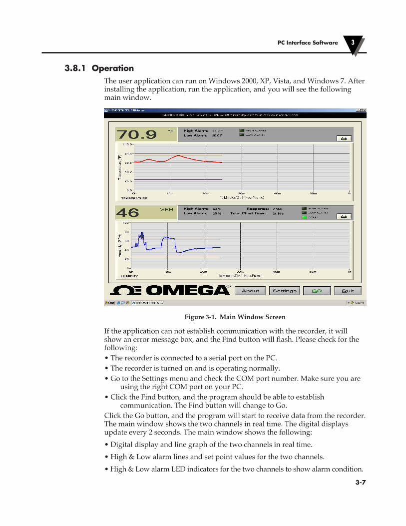
Figure 3-1. Main Window Screen
If the application can not establish communication with the recorder, it will show an error message box, and the Find button will flash. Please check for the following:• The recorder is connected to a serial port on the PC.• The recorder is turned on and is operating normally.• Go to the Settings menu and check the COM port number. Make sure you are
using the right COM port on your PC.• Click the Find button, and the program should be able to establish
communication. The Find button will change to Go.Click the Go button, and the program will start to receive data from the recorder. The main window shows the two channels in real time. The digital displays update every 2 seconds. The main window shows the following:• Digital display and line graph of the two channels in real time.• High & Low alarm lines and set point values for the two channels.• High & Low alarm LED indicators for the two channels to show alarm condition.
PC Interface Software 3
�3-7

• Response time & Total Chart time• Communication LED indicator.
Figure 3-2. Settings Menu - General Tab Screen
In the Settings menu (General Tab)• Selecting the “Save to File”, allows you to save the charted data coming from
the recorder into a data file. You can save up to 300,000 data points per channel @ 2 seconds sampling time.
• Selecting the “Show History Viewer”, displays a log of all the events happening with the application such as high & low alarm, start & stop of the application, etc.
PC Interface Software3
�3-8

PC Interface Software 3
�3-9
Figure 3-3. Settings Menu - Strip Chart Tab Screen
In the Setting menu (Strip Chart Tab)• You can select the Screen Chart Speed from 1 hour up to 32 days.• You can select the Pen (trace) colors for the two channels on the screen.• You can select the scaling of the two channels, either auto, manual, or logarithmic.In order to perform manual scaling, uncheck the “Auto Scale” and enter your desired upper and lower values for temperature and relative humidity.

PC Interface Software3
�3-10
Figure 3-4. Settings Menu - Re-scale/Calibrate/Memory Tab Screen
In the settings menu Re-scale/Calibrate/Memory Tab• You can re-scale the chart paper of the recorder within its range, both
temperature & humidity.• You can re-scale the chart paper to the factory default values by clicking the
“Defaults” button.• You can re-calibrate the humidity channel. The calibration procedure is the
same as what is described in section 3.4 of the manual, except you select the calibration values (33 & 75% RH), and click the Calibrate button.
• You can download the recorded data from the chart recorder.• You can erase the recorded data from the chart recorder.

3.9 PC User Application, CTXL-DPRThe CTXL-DPR dual process input circular chart recorder comes with a Windows based user application. This application allows you to do the following:• Monitor your dual process inputs in real time based on 1 hour, 1 Day, 7 Days,
and 32 Days Chart.• Save the dual process input data to a text file.• Select your process input range (Can be set anywhere from -10000 to +10000),
and Engineering units.• Select the Pen colors for the two channels on the screen.• Select your Chart time base (On the PC) from 1 hour up to 32 days.• Select the Upper & Lower values of the Y axis of the two channels, or
Logarithmic scale.• Perform Paper Chart re-scaling. To re-scale the chart paper to any other value
within the chart range.• Download the recorded data from the chart recorder to a text file.• Erase the recorded data from the chart recorder.• Change your process input Voltage or Current scale• COM port auto detect.• Enable/disable audible indicationsOperationThe user application runs on Windows 2000, XP, Vista, and Windows 7. After installing the application, run the application, and you will see the following on the main menu:• The line graph of the two process inputs in real time with the corresponding
Process input ranges and Engineering units.• The high & low alarm lines for the two channels.• The digital display of the two process inputs in real time.• The high & low alarm set points for the two channels as well as alarm LED
indicators.• Communication LED indicator.• Total chart time and Response time. The digital display updates every 2
seconds.• Print icon for two channels. You can print the line graph of each channel
separately to a printer (By clicking on the Print icon) after stopping the recording process.
PC Interface Software 3
�3-11

PC Interface Software3
�3-12
Figure 3-5. Main Window Screen
If the application can not establish communication with the recorder, it will show an error text message box, and the Find button will flash. Please check the following for communication error:• The recorder is connected to a serial port on the PC.• The recorder is turned on and is operating normally.• Go to the Settings menu and check the COM port number. Make sure you are
using the right COM port on your PC.• Click the Find button, and the program should be able to establish
communication. The Find button will then change to Go.Click the Go button, and the program starts to receive data from the recorder.

PC Interface Software 3
�3-13
3.9.1 Settings MenusThe settings menu has 3 tabs. In the General tab, you can do the following:• Select audible indication. The PC will beep every time either of the two
channels goes to high or low alarm conditions.• COM port auto detect. The program shows the available COM ports for your
selection.• Selecting the “Show History Viewer”, provides a log of all the events
happening with the application such as high & low alarm events, start & stop of the application, etc.
• Selecting the “Save to File”, allows you to save the charted data coming from the recorder into a data file. When you stop recording, the program will ask if you would like to save the data.
• Select your Engineering units (Up to 5 characters) for the two channels.• The menu shows the current input type and range. You can change the input
range by selecting other options. Please note that you can change the input rang within its type. For example, you can change the input from 4-20 mA to 0-20 mA, or 0-5 V to 0-10V, etc.
Figure 3-6. Settings Menu - General Tab Screen
PC Interface Software3
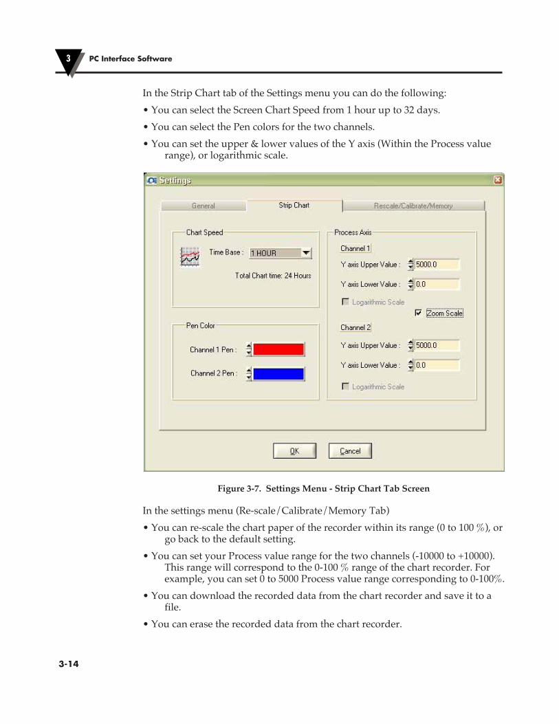
�3-14
In the Strip Chart tab of the Settings menu you can do the following:• You can select the Screen Chart Speed from 1 hour up to 32 days.• You can select the Pen colors for the two channels.• You can set the upper & lower values of the Y axis (Within the Process value
range), or logarithmic scale.
Figure 3-7. Settings Menu - Strip Chart Tab Screen
In the settings menu (Re-scale/Calibrate/Memory Tab)• You can re-scale the chart paper of the recorder within its range (0 to 100 %), or
go back to the default setting.• You can set your Process value range for the two channels (-10000 to +10000).
This range will correspond to the 0-100 % range of the chart recorder. For example, you can set 0 to 5000 Process value range corresponding to 0-100%.
• You can download the recorded data from the chart recorder and save it to a file.
• You can erase the recorded data from the chart recorder.
PC Interface Software 3
�3-15
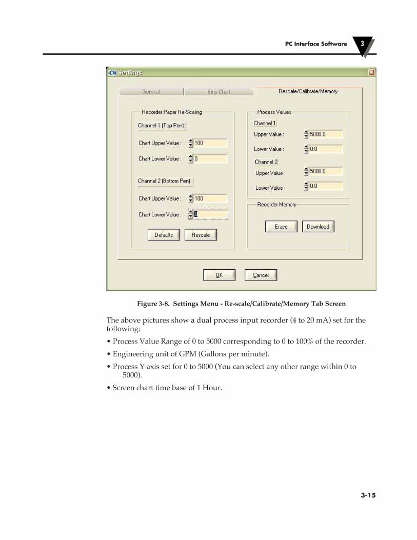
Figure 3-8. Settings Menu - Re-scale/Calibrate/Memory Tab Screen
The above pictures show a dual process input recorder (4 to 20 mA) set for the following:• Process Value Range of 0 to 5000 corresponding to 0 to 100% of the recorder.• Engineering unit of GPM (Gallons per minute).• Process Y axis set for 0 to 5000 (You can select any other range within 0 to
5000).• Screen chart time base of 1 Hour.
3.10 PC User Application, CTXL-DTCThe CTXL-DTC dual thermocouple input circular chart recorder comes with a Windows based user application. This application allows you to do the following:• Monitor your dual thermocouple inputs in real time based on 1 hour, 1 Day, 7
Days, and 32 Days Chart.• Save the input data to a text file.• Select the Pen colors for the two channels on the screen.• Select your Chart time base (On the PC) from 1 hour up to 32 days.• Select the Upper & Lower values of the Y axis of the two channels, or
Logarithmic scale.• Perform Chart paper re-scaling. To re-scale the chart paper to any other value
within the chart range.• Download the recorded data from the chart recorder to a text file.• Erase the recorded data from the chart recorder.• Change the thermocouple input (both channels) from K to J or T.• Perform Thermocouple input calibration (if necessary) at the temperature
points indicated in the menu.• COM port auto detect.• Enable/disable audible indications
OperationThe user application runs on Windows 2000, XP, Vista, and Seven. After installing the application, run the application, and you will see the following on the main menu:• The line graph of the two process inputs in real time with the corresponding
Process input ranges and Engineering units.• The high & low alarm lines for the two channels.• The digital display of the two thermocouple inputs in real time.• The high & low alarm set points for the two channels as well as alarm LED
indicators.• Communication LED indicator.• Total chart time and Response time. The digital display updates every 2
seconds.• Print icon for two channels. You can print the line graph of each channel
separately to a printer (By clicking on the Print icon) after stopping the recording process.
PC Interface Software3
�3-16
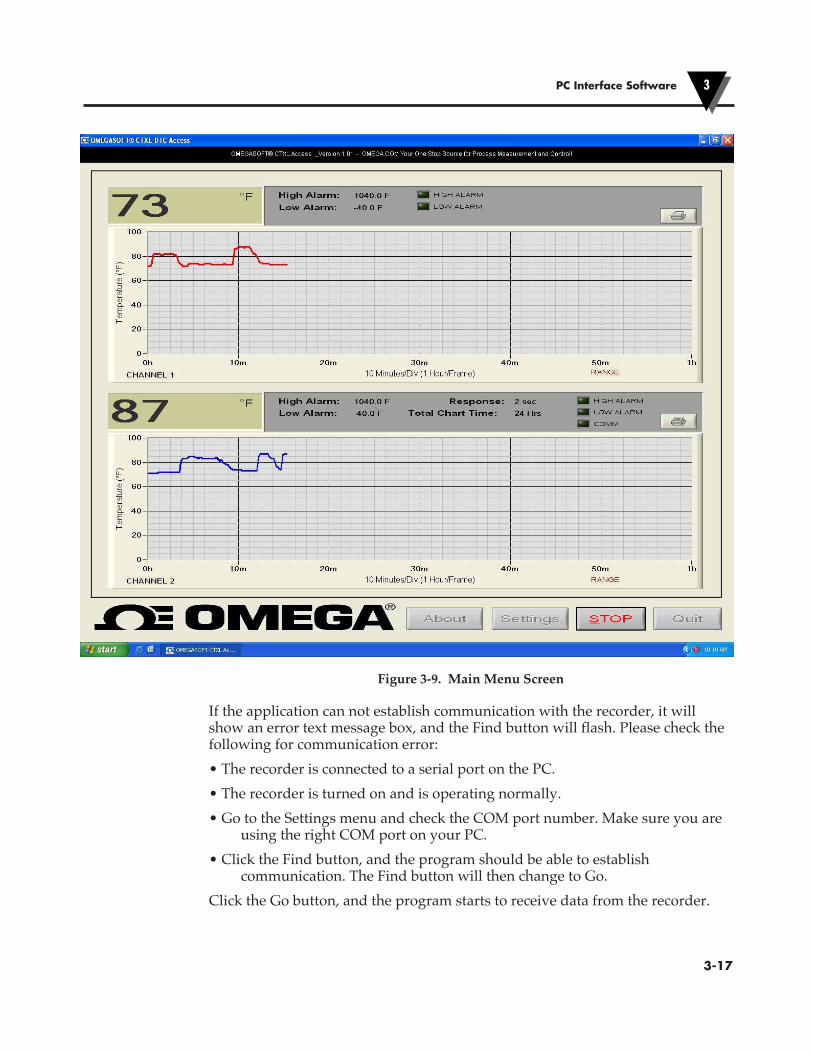
Figure 3-9. Main Menu Screen
If the application can not establish communication with the recorder, it will show an error text message box, and the Find button will flash. Please check the following for communication error:• The recorder is connected to a serial port on the PC.• The recorder is turned on and is operating normally.• Go to the Settings menu and check the COM port number. Make sure you are
using the right COM port on your PC.• Click the Find button, and the program should be able to establish
communication. The Find button will then change to Go.Click the Go button, and the program starts to receive data from the recorder.
PC Interface Software 3
�3-17

Settings MenusThe settings menu has 3 tabs. In the General tab, you can do the following:• Select audible indication. The PC will beep every time either of the two
channels goes to high or low alarm conditions.• COM port auto detect. The program shows the available COM ports for your
selection.• Selecting the “Show History Viewer”, provides a log of all the events
happening with the application such as high & low alarm events, start & stop of the application, etc.
• Selecting the “Save to File”, allows you to save the charted data coming from the recorder into a data file. When you stop recording, the program will ask if you would like to save the data.
Figure 3-10. Settings Menu - General Tab Screen
PC Interface Software3
�3-18

In the Strip Chart tab of the Settings menu you can do the following:• You can select the Screen Chart Speed from 1 hour up to 32 days.• You can select the Pen colors for the two channels.• You can set the upper & lower values of the Y axis, auto or logarithmic scale.
Figure 3-11. Settings Menu (Strip Chart Tab) Screen
In the settings menu (Re-scale/Calibrate/Memory Tab)• You can re-scale the chart paper of the recorder within its range, or go back to
the default setting.• You can download the recorded data from the chart recorder and save it to a
file.• You can erase the recorded data from the chart recorder.• You can change the thermocouple input type from K to J or T.
PC Interface Software 3
�3-19
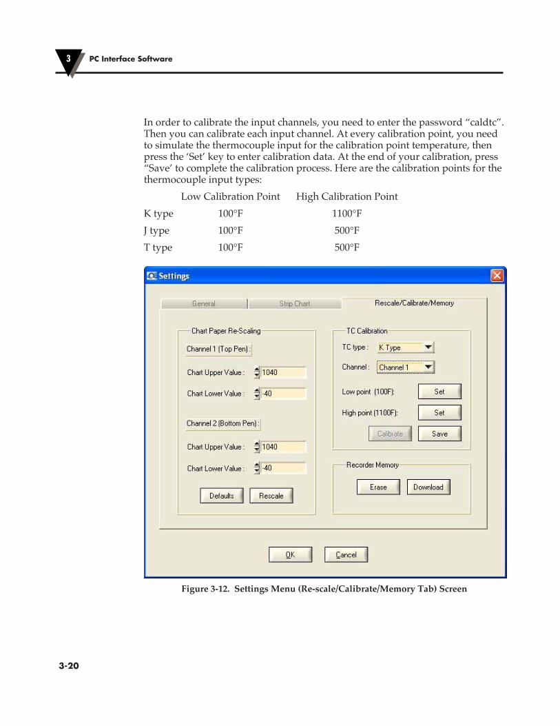
In order to calibrate the input channels, you need to enter the password “caldtc”. Then you can calibrate each input channel. At every calibration point, you need to simulate the thermocouple input for the calibration point temperature, then press the ‘Set’ key to enter calibration data. At the end of your calibration, press “Save’ to complete the calibration process. Here are the calibration points for the thermocouple input types: Low Calibration Point High Calibration PointK type 100°F 1100°FJ type 100°F 500°FT type 100°F 500°F
Figure 3-12. Settings Menu (Re-scale/Calibrate/Memory Tab) Screen
PC Interface Software3
�3-20
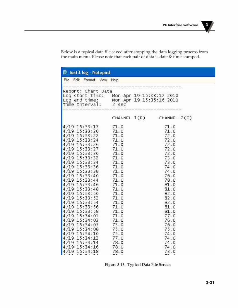
Below is a typical data file saved after stopping the data logging process from the main menu. Please note that each pair of data is date & time stamped.
Figure 3-13. Typical Data File Screen
PC Interface Software 3
�3-21

3.11 PC User Application, CTXL-PHThe CTXL-PH pH & RTD input circular chart recorder comes with a Windows based user application. This application allows you to do the following:• Monitor your pH and RTD temperature inputs in real time based on 1 hour, 1
Day, 7 Days, and 32 Days Chart.• Save the input data to a text file.• Select the Pen colors for the two channels on the screen.• Select your Chart time base (On the PC) from 1 hour up to 32 days.• Select the Upper & Lower values of the Y axis of the two channels, or
Logarithmic scale.• Perform Chart paper re-scaling. To re-scale the chart paper to any other value
within the chart range.• Download the recorded data from the chart recorder to a text file.• Erase the recorded data from the chart recorder.• Perform pH & RTD input calibration (if necessary) at the points indicated in
the menu.• COM port auto detect.• Enable/disable audible indications
OperationThe user application runs on Windows 2000, XP, Vista, and Seven. After installing the application, run the application, and you will see the following on the main menu:• The line graph of pH and RTD temperature inputs in real time.• The high & low alarm lines for the two channels.• The digital display of pH and temperature inputs in real time.• The high & low alarm set points for the two channels as well as alarm LED
indicators.• Communication LED indicator.• Total chart time and Response time. The digital display updates every 2
seconds.• Print icon for two channels. You can print the line graph of each channel
separately to a printer (By clicking on the Print icon) after stopping the recording process.
PC Interface Software3
�3-22
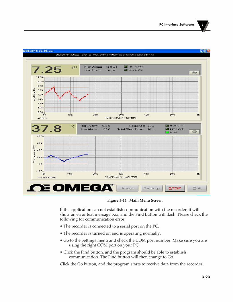
Figure 3-14. Main Menu Screen
If the application can not establish communication with the recorder, it will show an error text message box, and the Find button will flash. Please check the following for communication error:• The recorder is connected to a serial port on the PC.• The recorder is turned on and is operating normally.• Go to the Settings menu and check the COM port number. Make sure you are
using the right COM port on your PC.• Click the Find button, and the program should be able to establish
communication. The Find button will then change to Go.Click the Go button, and the program starts to receive data from the recorder.
PC Interface Software 3
�3-23

Settings MenusThe settings menu has 3 tabs. In the General tab, you can do the following:• Select audible indication. The PC will beep every time either of the two
channels goes to high or low alarm conditions.• COM port auto detect. The program shows the available COM ports for your
selection.• Selecting the “Show History Viewer”, provides a log of all the events
happening with the application such as high & low alarm events, start & stop of the application, etc.
• Selecting the “Save to File”, allows you to save the charted data coming from the recorder into a data file. When you stop recording, the program will ask if you would like to save the data.
Figure 3-15. Settings Menu – General Tab Screen
PC Interface Software3
�3-24
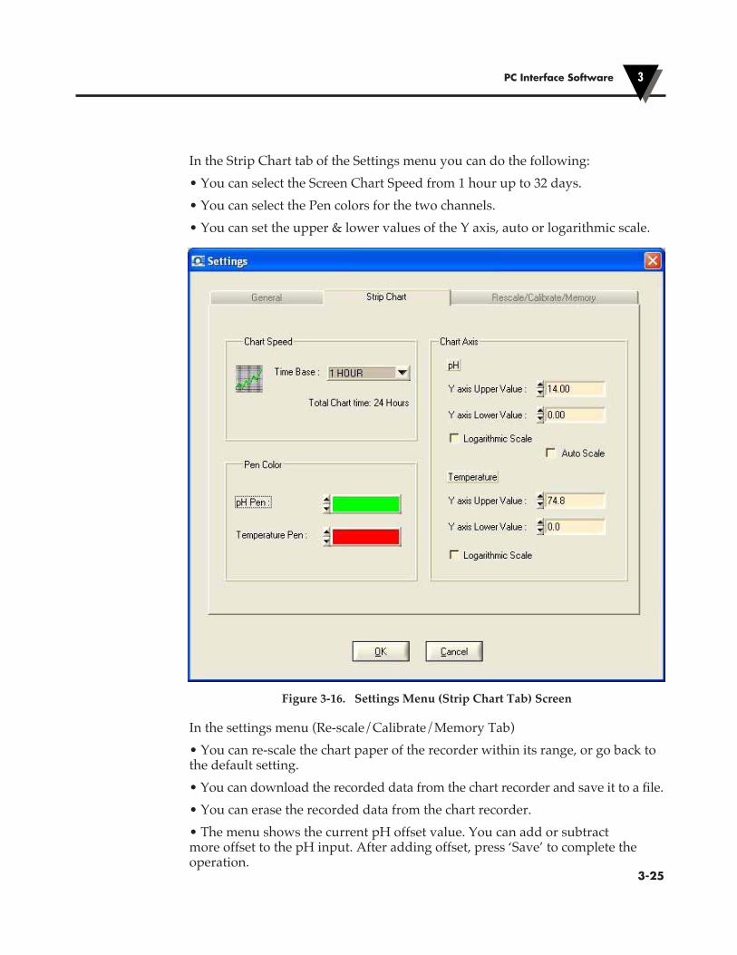
In the Strip Chart tab of the Settings menu you can do the following:• You can select the Screen Chart Speed from 1 hour up to 32 days.• You can select the Pen colors for the two channels.• You can set the upper & lower values of the Y axis, auto or logarithmic scale.
Figure 3-16. Settings Menu (Strip Chart Tab) Screen
In the settings menu (Re-scale/Calibrate/Memory Tab)• You can re-scale the chart paper of the recorder within its range, or go back to the default setting.• You can download the recorded data from the chart recorder and save it to a file.• You can erase the recorded data from the chart recorder.• The menu shows the current pH offset value. You can add or subtract more offset to the pH input. After adding offset, press ‘Save’ to complete the operation.
PC Interface Software 3
�3-25
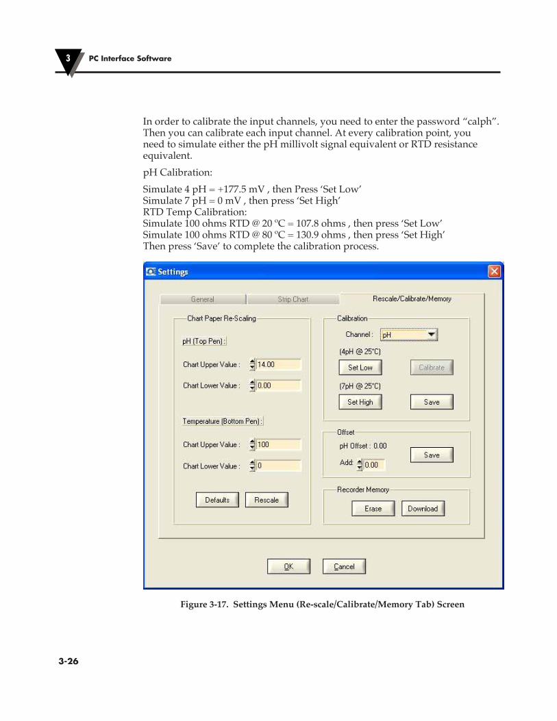
In order to calibrate the input channels, you need to enter the password “calph”. Then you can calibrate each input channel. At every calibration point, you need to simulate either the pH millivolt signal equivalent or RTD resistance equivalent.pH Calibration:Simulate 4 pH = +177.5 mV , then Press ‘Set Low’ Simulate 7 pH = 0 mV , then press ‘Set High’ RTD Temp Calibration: Simulate 100 ohms RTD @ 20 ºC = 107.8 ohms , then press ‘Set Low’ Simulate 100 ohms RTD @ 80 ºC = 130.9 ohms , then press ‘Set High’ Then press ‘Save’ to complete the calibration process.
Figure 3-17. Settings Menu (Re-scale/Calibrate/Memory Tab) Screen
PC Interface Software3
�3-26

�4-1
Specifications4
4.1 GeneralDisplay: Custom made 4 Digit Dual LCD, BacklitDisplay Data Sampling Rate: Once per 2 secondsChart Speed: 1 Day, 7 Days, 32 DaysChart Response time: 0.5 min, 3.5 min, 16 min for 1, 7, 32 days respectivelyKeypad response: 250 msecChart Paper: 203 mm (8") circular, Linear radial divisions,Double Sided: Chart Drive Type: Stepper Motor Accuracy: 1% RotationChart Hold Down: Magnetic HubPen Drive Type: Stepper Motor, Linear screw drive Deadband: 1ºF (0.5ºC) or 1% RH reference to - TRH modelPen Lift: Automatic on Door opening- Pens are door
mounted and swing clear of the chart when door opens
Lights: LCD Backlight & Chart lights Turns on/off using Light key In Battery mode, it turns on for 3 seconds In DC adapter mode, it toggles on/offDisplay Modes – Press Mode Key MAX: Displays Maximum value MIN: Displays Minimum value AVG: Displays Average value T1-T2: Displays differential temperature between Channel 1 & 2 (Dual Thermocouple Model only)ºC ºF Key: Displays temperature in Degree C or F
(Model CTXL-TRH and CTXL-DTC)Clock key: Displays the clock time & date for 3 secondsConfiguration Modes – Press Config key High Alarm – Channel 1 Low Alarm – Channel 1 High Alarm – Channel 2 Low Alarm – Channel 2 Clock – Hour (Military time 0-23) Clock- Minute (0-59) Date - Month (1-12) Date – Day (1-31)

Clock Battery Backup: 0.33 F Super Capacitor, Holds Clock information for about 14 days when main power is removed.
White Box Key: Press & hold for 3 seconds to Lock/Unlock When in Lock mode, all keys are inactive except for the Power, Light, Mode, Clock, and the White Box keys
Pens Going to Home Position: At the Power Up Chart Door is opened Input Probe is open Chart is re-scaledAudible Alarm: Piezo-electric beeperAlarm Outputs Two separate relay contacts & two voltage outputs Relay Contacts: 2A @ 30 Vdc Voltage Output: 100 mA to drive an external relayOperating Ambient Temperature: 0 to 49ºC (32 to 120ºF)Operating Relative Humidity: 0 to 98% RHPower: Four “D” size alkaline Batteries or DC adaptorBattery Life: 3 Months under normal conditionsBattery Status Indication: Icon on the LCDAC Adapter 100 to 240 VAC, 50-60 Hz input Output: 9Vdc @ 1.7A, UL, CE, FCC Marked Output Plug (Female): Center Positive, Coax 2.0/5.5/10 mm Output Cable: 1.8 m (6 Ft.) LongSerial PC Communication: RS232, 2 way, 9600 Baud, 8 Bits Data, 1 Stop Bit, No ParityRS232 Adaptor - RJ12 to 9 pin RJ12 Pin # 9 pin D connector Pin # D - Sub Connector, Female 3 Tx 2 Rx 4 Rx 3 Tx 5 GND 5 GND Memory: 256K EEPROM, Circular Buffer - Holds 2.8 Chart
revolutions worth of dataPC Communication – See Chapter 3 for more details Chart Rescale: Rescale one or both pens
Restore Default Factory settings Data Transfer: Download stored data and save into a data file Erase stored data from recorder’s memory Get Data in Real Time: Read current data from channel 1 and 2Mounting: Key hole slots for wall mounting Foot cover for Bench top use
Specifications4
�4-2
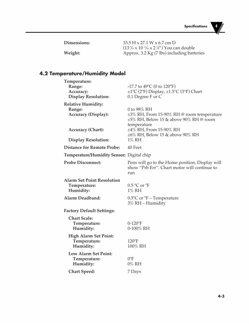
Specifications 4
�4-3
Dimensions: 33.5 H x 27.1 W x 6.7 cm D (13 3⁄16 x 10 11⁄16 x 2 5⁄8”) You can double Weight: Approx. 3.2 Kg (7 lbs) including batteries
4.2 Temperature/Humidity ModelTemperature: Range: -17.7 to 49ºC (0 to 120ºF) Accuracy: ±1ºC (2ºF) Display, ±1.5°C (3°F) Chart Display Resolution: 0.1 Degree F or CRelative Humidity: Range: 0 to 98% RH Accuracy (Display): ±3% RH, From 15-90% RH @ room temperature ±5% RH, Below 15 & above 90% RH @ room temperature Accuracy (Chart): ±4% RH, From 15-90% RH ±6% RH, Below 15 & above 90% RH Display Resolution: 1% RHDistance for Remote Probe: 40 FeetTemperature/Humidity Sensor: Digital chipProbe Disconnect: Pens will go to the Home position, Display will
show “Prb Err”. Chart motor will continue to run
Alarm Set Point Resolution Temperature: 0.5 ºC or ºF Humidity: 1% RHAlarm Deadband: 0.5ºC or ºF – Temperature 3% RH – HumidityFactory Default Settings: Chart Scale: Temperature: 0-120ºF Humidity: 0-100% RH High Alarm Set Point: Temperature: 120ºF Humidity: 100% RH Low Alarm Set Point: Temperature: 0ºF Humidity: 0% RH Chart Speed: 7 Days
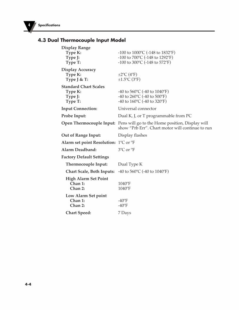
Specifications4
�4-4
4.3 Dual Thermocouple Input ModelDisplay Range Type K: -100 to 1000ºC (-148 to 1832ºF) Type J: -100 to 700ºC (-148 to 1292ºF) Type T: -100 to 300ºC (-148 to 572ºF)Display Accuracy Type K: ±2ºC (4ºF) Type J & T: ±1.5ºC (3ºF)Standard Chart Scales Type K: -40 to 560ºC (-40 to 1040ºF) Type J: -40 to 260ºC (-40 to 500ºF) Type T: -40 to 160ºC (-40 to 320ºF)Input Connection: Universal connectorProbe Input: Dual K, J, or T programmable from PCOpen Thermocouple Input: Pens will go to the Home position, Display will
show “Prb Err”. Chart motor will continue to runOut of Range Input: Display flashesAlarm set point Resolution: 1ºC or ºFAlarm Deadband: 3ºC or ºFFactory Default Settings Thermocouple Input: Dual Type K Chart Scale, Both Inputs: -40 to 560ºC (-40 to 1040ºF) High Alarm Set Point Chan 1: 1040ºF Chan 2: 1040ºF Low Alarm Set point Chan 1: -40ºF Chan 2: -40ºF Chart Speed: 7 Days
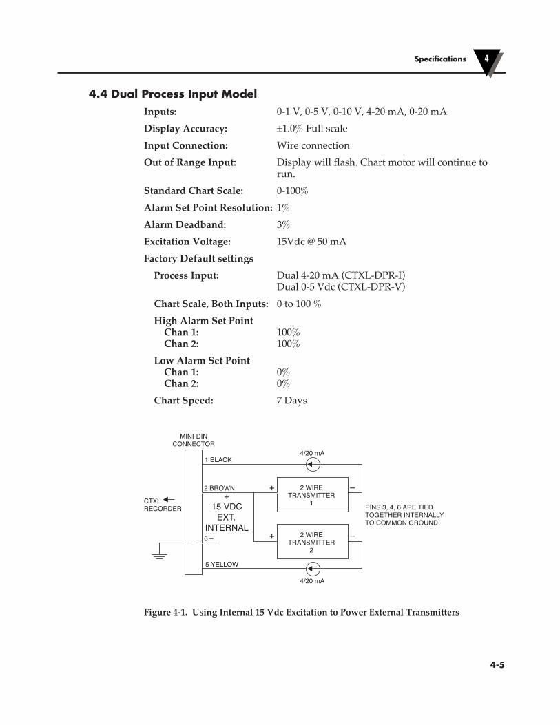
Specifications 4
�4-5
4.4 Dual Process Input ModelInputs: 0-1 V, 0-5 V, 0-10 V, 4-20 mA, 0-20 mADisplay Accuracy: ±1.0% Full scaleInput Connection: Wire connectionOut of Range Input: Display will flash. Chart motor will continue to
run.Standard Chart Scale: 0-100%Alarm Set Point Resolution: 1%Alarm Deadband: 3%Excitation Voltage: 15Vdc @ 50 mAFactory Default settings Process Input: Dual 4-20 mA (CTXL-DPR-I) Dual 0-5 Vdc (CTXL-DPR-V) Chart Scale, Both Inputs: 0 to 100 % High Alarm Set Point Chan 1: 100% Chan 2: 100% Low Alarm Set Point Chan 1: 0% Chan 2: 0% Chart Speed: 7 Days
Figure 4-1. Using Internal 15 Vdc Excitation to Power External Transmitters
2 WIRETRANSMITTER
1
2 BROWN
5 YELLOW
6 –
1 BLACK4/20 mA
+
+
–
–
4/20 mA
MINI-DINCONNECTOR
+15 VDC
EXT.INTERNAL
CTXL RECORDER PINS 3, 4, 6 ARE TIED
TOGETHER INTERNALLYTO COMMON GROUND
2 WIRETRANSMITTER
2

Specifications4
�4-6
4.5 CTXL-pH ModelpH Input
Range: 0 to 12 pH (Chart paper) 0 to 14 pH (Display)Accuracy: 0.1 pH (Display and Chart)Resolution: 0.1 pH (Chart paper) 0.01 pH (Display)Response Time: 2 secondspH Connection: BNC connectorInput Impedance: 1012 ohms, TypicalAutomatic Temperature 0 to 100ºC (32 to 212ºF) Compensation:
Temperature InputInput: 100 Ohms RTD, European curve (0.00385)Range: 0 to 100ºC (32 to 212ºF)Accuracy: 1ºC (Display and Chart)Resolution: 1ºC (Chart paper) 0.1ºC or ºF (Display)Response Time: 2 secondsRTD Connection: Terminal Block
The Chart paper is printed for pH (0 – 12) and ºC (0 – 120). The following table shows all the optional accessories:
Model No. Description
CTPH-CDC 100 Double sided 1 Day chart paper
CTPH-CWC 100 Double sided 7 Days chart paper
CTPH-CMC 100 Double sided 32 Days chart paper
PHE-7352-15-PT100 Heavy Duty pH Electrode with 100 ohms RTD sensor
PHE-6510 Submersible Flat surface pH Electrode
PHE-1311 General Purpose pH Electrode
PHA-4 4 pH Buffer Solution, 475 ml bottle
PHA-7 7 pH Buffer Solution, 475 ml bottle
PHA-10 10 pH Buffer Solution, 475 ml bottle

�5-1
Maintaining the Recorder5
5.1 General Considerations
73
DUST
DUST
DUST
DUST
73
SO
LVE
NT
12131
Keep the recorder in a dry place. If it gets wet, wipe the case as soon as possible to get rid of any moisture.
Do not expose the recorder to temperatures other than those stated in the specifications. The recorder can operate in temperatures as high as 120°F (49°C) or as low as 32°F (0°C).
73
DUST
DUST
DUST
DUST
73
SO
LVE
NT
12131
73
DUST
DUST
DUST
DUST
73
SO
LVE
NT
12131
Handle the recorder carefully (DO NOT DROP IT).
Keep the recorder away from excessive dirt and dust. Do not use the recorder or the sensor in a corrosive air environment.
Do not use strong cleaning solvents or alcohol when cleaning the outer case. Refer to Section 8.3 for more details.
Do not use old or weak batteries in the recorder. It is important to change the batteries monthly or when you see the LO BAT indicator (see Fig. 2-6).
73
DUST
DUST
DUST
DUST
73
SO
LVE
NT
12131
73
DUST
DUST
DUST
DUST
73
SO
LVE
NT
12131
73
DUST
DUST
DUST
DUST
73
SO
LVE
NT
12131
�5-2
Notes
Maintaining the Recorder5
NOTE
All humidity sensors are susceptible to contamination from outside sources that can affect accuracy and response time. Take care to prevent excessive contamination by dirt, oil, grease, solvents, or a corrosive air environment.
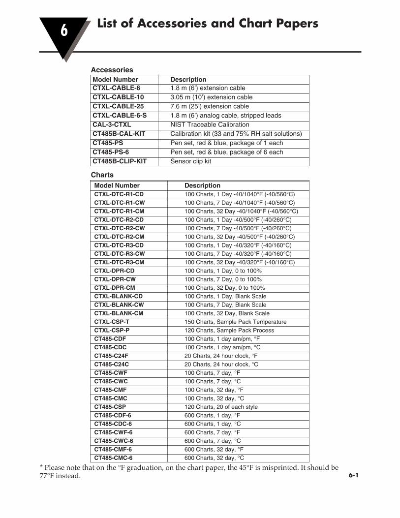
�6-1
List of Accessories and Chart Papers6
Model Number Description CTXL-DTC-R1-CD 100 Charts, 1 Day -40/1040°F (-40/560°C) CTXL-DTC-R1-CW 100 Charts, 7 Day -40/1040°F (-40/560°C) CTXL-DTC-R1-CM 100 Charts, 32 Day -40/1040°F (-40/560°C) CTXL-DTC-R2-CD 100 Charts, 1 Day -40/500°F (-40/260°C) CTXL-DTC-R2-CW 100 Charts, 7 Day -40/500°F (-40/260°C) CTXL-DTC-R2-CM 100 Charts, 32 Day -40/500°F (-40/260°C) CTXL-DTC-R3-CD 100 Charts, 1 Day -40/320°F (-40/160°C) CTXL-DTC-R3-CW 100 Charts, 7 Day -40/320°F (-40/160°C) CTXL-DTC-R3-CM 100 Charts, 32 Day -40/320°F (-40/160°C) CTXL-DPR-CD 100 Charts, 1 Day, 0 to 100% CTXL-DPR-CW 100 Charts, 7 Day, 0 to 100% CTXL-DPR-CM 100 Charts, 32 Day, 0 to 100% CTXL-BLANK-CD 100 Charts, 1 Day, Blank Scale CTXL-BLANK-CW 100 Charts, 7 Day, Blank Scale CTXL-BLANK-CM 100 Charts, 32 Day, Blank Scale CTXL-CSP-T 150 Charts, Sample Pack Temperature CTXL-CSP-P 120 Charts, Sample Pack Process CT485-CDF 100 Charts, 1 day am/pm, °F CT485-CDC 100 Charts, 1 day am/pm, °C CT485-C24F 20 Charts, 24 hour clock, °F CT485-C24C 20 Charts, 24 hour clock, °C CT485-CWF 100 Charts, 7 day, °F CT485-CWC 100 Charts, 7 day, °C CT485-CMF 100 Charts, 32 day, °F CT485-CMC 100 Charts, 32 day, °C CT485-CSP 120 Charts, 20 of each style CT485-CDF-6 600 Charts, 1 day, °F CT485-CDC-6 600 Charts, 1 day, °C CT485-CWF-6 600 Charts, 7 day, °F CT485-CWC-6 600 Charts, 7 day, °C CT485-CMF-6 600 Charts, 32 day, °F CT485-CMC-6 600 Charts, 32 day, °C
Accessories
Charts
Model Number Description CTXL-CABLE-6 1.8 m (6’) extension cable CTXL-CABLE-10 3.05 m (10’) extension cable CTXL-CABLE-25 7.6 m (25’) extension cable CTXL-CABLE-6-S 1.8 m (6’) analog cable, stripped leads CAL-3-CTXL NIST Traceable Calibration CT485B-CAL-KIT Calibration kit (33 and 75% RH salt solutions) CT485-PS Pen set, red & blue, package of 1 each CT485-PS-6 Pen set, red & blue, package of 6 each CT485B-CLIP-KIT Sensor clip kit
* Please note that on the °F graduation, on the chart paper, the 45°F is misprinted. It should be 77°F instead.

�6-2
List of Accessories and Charts Papers6
Notes
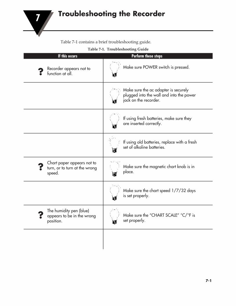
�7-1
Troubleshooting the Recorder7
Table 7-1 contains a brief troubleshooting guide.Table 7-1. Troubleshooting Guide
If this occurs Perform these steps
?
Recorder appears not to function at all.
Make sure POWER switch is pressed.
Make sure the ac adapter is securely plugged into the wall and into the power jack on the recorder.
If using fresh batteries, make sure they are inserted correctly.
If using old batteries, replace with a fresh set of alkaline batteries.
?
Chart paper appears not to turn, or to turn at the wrong speed.
Make sure the magnetic chart knob is in place.
Make sure the chart speed 1/7/32 days is set properly.
?
The humidity pen (blue) appears to be in the wrong position.
Make sure the “CHART SCALE” °C/°F is set properly.

Troubleshooting the Recorder7
�7-2
Make sure the pens are fresh. Remove a pen and test it on a piece of chart paper. Insert new pens if necessary.
Bulbs don’t light.Bulbs are blown. Replace them with new bulbs.
Make sure pen caps are removed (and secured in a safe location).
Check that the pens are locked firmly in position in their holders.
?
?
The pens do not appear to be leaving traces on the paper.
?The pens do not appear to be leaving traces on the paper.
Make sure the door is completely closed and the latch button is in the uppermost position. It may be necessary to squeeze the case slightly to close the latch completely.
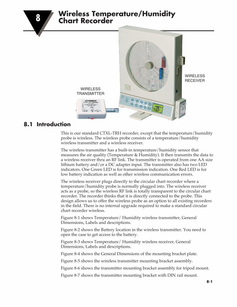
�8-1
Wireless Temperature/Humidity Chart Recorder8
8.1 IntroductionThis is our standard CTXL-TRH recorder, except that the temperature/humidity probe is wireless. The wireless probe consists of a temperature/humidity wireless transmitter and a wireless receiver.The wireless transmitter has a built-in temperature/humidity sensor that measures the air quality (Temperature & Humidity). It then transmits the data to a wireless receiver thru an RF link. The transmitter is operated from one AA size lithium battery and/or a DC adapter input. The transmitter also has two LED indicators. One Green LED is for transmission indication. One Red LED is for low battery indication as well as other wireless communication errors.The wireless receiver plugs directly to the circular chart recorder where a temperature/humidity probe is normally plugged into. The wireless receiver acts as a probe, so the wireless RF link is totally transparent to the circular chart recorder. The recorder thinks that it is directly connected to the probe. This design allows us to offer the wireless probe as an option to all existing recorders in the field. There is no internal upgrade required to make a standard circular chart recorder wireless.Figure 8-1 shows Temperature/ Humidity wireless transmitter, General Dimensions, Labels and descriptions.Figure 8-2 shows the Battery location in the wireless transmitter. You need to open the case to get access to the battery.Figure 8-3 shows Temperature/ Humidity wireless receiver, General Dimensions, Labels and descriptions.Figure 8-4 shows the General Dimensions of the mounting bracket plate.Figure 8-5 shows the wireless transmitter mounting bracket assembly.Figure 8-6 shows the transmitter mounting bracket assembly for tripod mount.Figure 8-7 shows the transmitter mounting bracket with DIN rail mount.
WIRELESS RECEIVER
WIRELESS TRANSMITTER

Wireless Temperature/Humidity Chart Recorder8
�8-2
Figure 8-1. Temperature/Humidity Wireless Transmitter, General Dimensions, Labels and Descriptions
Figure 8-2. Battery Location in the Wireless Transmitter
CTXL-PT SeriesWireless
Temperature/HumidityTransmitter
BATTERY POWER SWITCH
DC ADAPTER INPUT
USB PCINTERFACE
TRANSMIT LEDINDICATOR
LOW BATTERY& COMM ERRORLED INDICATOR
2.750
2.00
2.125
Ø.500
TEMPERATURE/HUMIDITYSENSOR PROBE
FCC LABEL LOCATEDON BACK SIDE OF TRANSMITTER.
OFFON
POWERDC POWERINPUT
5V100 mA
- +
ROMEGA
-W9(915MHz)
-W8(868MHz)
LO-B
AT/E
RR
OR
TX
US
BP
OR
T
CONFIG
PR
OB
E
This device complies with Part 15 of the FCC rules. Operation is subject to the following two conditions: 1) This device may not cause harmful interference; 2) This device must accept any interference received, including interference that may cause undesired operation.
FCC ID: WR3-CTXLPTIC: 8205A-CTXLPT
PATENT PENDING
LO-B
AT
/ER
RO
R
TX
POWEROFF
CONFIGONDC POWER
INPUT
5 V100 MA
– +
PR
OB
E
US
BP
OR
T
–W9(915MHz)
–W8(868MHz)
CTXL-PT SERIESWIRELESS
TEMPERATURE/HUMIDITYTRANSMITTER
!
TM
+– 3.6VDC LITHIUM BATT
J3
J7 S1
J1D4D3

Wireless Temperature/Humidity Chart Recorder 8
�8-3
Figure 8-3. Temperature/Humidity Wireless Receiver, General Dimensions, Labels and Descriptions
Figure 8-4. Mounting Bracket Plate General Dimensions
USB PCINTERFACE
NORMAL/CONFIGURATIONSWITCHSELECTION
COMM ERRORLED INDICATOR
RECEIVELED
INDICATOR
2.750
2.00
TO C
TX
L C
HA
RT
RE
CO
RD
ER
0.8000.300
FCC LABEL LOCATEDON BACK SIDE OF
RECEIVER
CTXL-PR SERIES
WIRELESSTEMPERATUREAND HUMIDITY
RECEIVER NORMAL
USBPORT
CONFIG
ERROR
RX –W9(915MHz)–W8(868MHz)
TM
This device complies with Part 15 of the FCC rules. Operation is subject to the following two conditions: 1) This device may not cause harmful interference; 2) This device must accept any interference received,including interference that may cause undesiredoperation.
!
LOCATION OF CASEMOUNTING SCREWS CL
LC
2.125
1.375
0.125 DIA.2 PLCSMOUNTINGHOLES
1.00
2.500
3.200
3.500
2.000
0.090
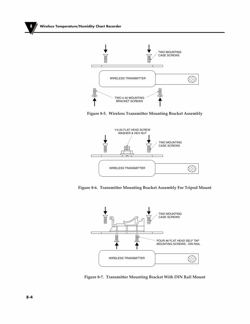
Wireless Temperature/Humidity Chart Recorder8
�8-4
Figure 8-5. Wireless Transmitter Mounting Bracket Assembly
Figure 8-6. Transmitter Mounting Bracket Assembly For Tripod Mount
Figure 8-7. Transmitter Mounting Bracket With DIN Rail Mount
WIRELESS TRANSMITTER
TWO MOUNTINGCASE SCREWS
TWO 4-40 MOUNTINGBRACKET SCREWS
FOUR #6 FLAT HEAD SELF TAPMOUNTING SCREWS - DIN RAIL
TWO MOUNTINGCASE SCREWS
WIRELESS TRANSMITTER
1/4-20 FLAT HEAD SCREWWASHER & HEX NUT
TWO MOUNTINGCASE SCREWS
WIRELESS TRANSMITTER

Wireless Temperature/Humidity Chart Recorder 8
�8-5
8.2 ConfigurationThe wireless transmitter and receiver have the following factory default configuration:Transmission time interval: 2 secondsChannel Frequency: 915 MHz (US & Canada) or 868 MHz (Europe) Unit ID: 00 (Both transmitter & receiver)The user does not have to do any configuration to the transmitter or the receiver if the factory configuration is satisfactory. However, if the user wants to change the configuration, then you need to run the configuration software that comes with the unit. Through the configuration software, the user can change the transmission interval, channel frequency and the unit ID number. First install the configuration software on your PC.Configuring the wireless Transmitter – Turn off the battery power. Connect the transmitter to the USB port of the PC with the cable provided. Run the configuration software. Figure 8-8 shows the main menu of the software. The buttons and the menu selections are described as follows: Run – It will display the temperature/humidity in real time. Program – It will save the new settings to the transmitter. Read – It will read the current settings of the transmitter Settings – It will take you to the communication settings menu Frequency – You can select between 910/ 915/920 MHz frequencies. Time interval – You can select from 2 seconds up to 2 minutes. Unit ID - You can select a unit ID from 00 to 63.
Figure 8-8. Wireless Transmitter, Main Menu

Wireless Temperature/Humidity Chart Recorder8
�8-6
You can have up to a total of 64 wireless transmitters in one location with different unit ID numbers, so that there will not be any conflict between any of the transmitters.If you select the Broadcast option, the transmitter will transmit to any receiver in the area at the same frequency regardless of its unit ID number.After saving the new configuration, exit the program. Un-plug the transmitter from the USB port, turn the battery power back on and you are good to go.Configuring the wireless Receiver – Unplug the receiver from the chart recorder. Connect the receiver to the USB port of the PC with the cable provided. Set the slide switch to “Config”. Run the configuration software. Figure 8-9 shows the main menu of the software. The buttons and the menu selections are described as follows:Run – It will display the temperature/humidity in real time from the transmitter. There is an RF signal strength gauge where it shows the signal strength of the transmitter being received by the wireless receiver. This is a guide to show the user how to install the transmitter with respect to the receiver so that you maintain good signal strength and as a result good and reliable RF communication.Program – It will save the new settings to the receiver. Read – It will read the current settings of the receiver Settings – It will take you to the communication settings menu Frequency – You can select between 910/915/920 MHz frequencies. Time interval – You can select from 2 seconds up to 2 minutes. Unit ID - You can select a unit ID from 00 to 63.
Figure 8-9. Wireless Receiver, Main Menu
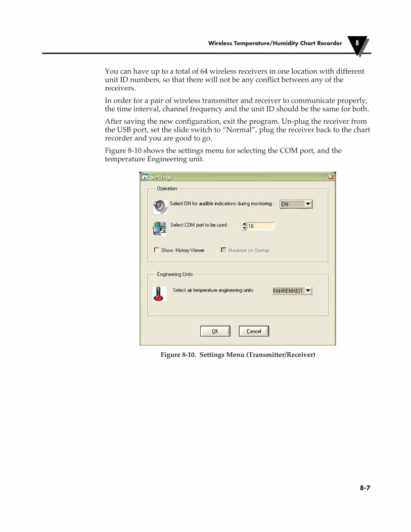
Wireless Temperature/Humidity Chart Recorder 8
�8-7
You can have up to a total of 64 wireless receivers in one location with different unit ID numbers, so that there will not be any conflict between any of the receivers.In order for a pair of wireless transmitter and receiver to communicate properly, the time interval, channel frequency and the unit ID should be the same for both.After saving the new configuration, exit the program. Un-plug the receiver from the USB port, set the slide switch to “Normal”, plug the receiver back to the chart recorder and you are good to go.Figure 8-10 shows the settings menu for selecting the COM port, and the temperature Engineering unit.
Figure 8-10. Settings Menu (Transmitter/Receiver)

Wireless Temperature/Humidity Chart Recorder8
�8-8
8-3 - SpecificationsGENERAL Temperature: Range: -18 to 49°C (0 to 120°F) Display Accuracy: 1°C (2°F) Chart Accuracy: 1.5°C (3°F) Display Resolution: 0.1° F or CRelative Humidity: Range: 2 to 98% RH Display Accuracy: 3% RH (From 15 to 90% RH), 5% RH (< 15 or >90 % RH) Chart Accuracy: 4% RH (From 15 to 90% RH), 6% RH (<15 or >90 % RH) Display Resolution: 1% RHDisplay Data Sampling Rate: Once every 2 seconds
WIRELESS TRANSMITTER Transmit time interval: 2 seconds – default, 10 seconds,
30 seconds, 1 minute, 2 minutesRadio Frequency: ISM 915 MHz or ISM 868 MHzRF Power Output: 5 dBm (3.16 mW)Approvals: Model: CTXL-TRH-(W or G)-W9: FCC, Class A, 915 MHz (US & Canada) Model: CTXL-TRH-(W or G)-W8: CE, 868 MHz (Europe) Model: CTXL-PT-W9: FCC, Class A, 915 MHz (US & Canada) Model: CTXL-PT-W8: CE, 868 MHz (Europe)RF Link Range: Outdoor, line of sight: Up to 90 m (300’) Indoor/urban: Up to 33.5 m (110’)PC Interface: USB, 115200 baud rate, 8-bit Data, 1 Stop bit, No ParityOperating Environment: -18 to 49°C (0 to 120°F), 2 to 98% RHLED indicators: Green LED: Transmit indication, blinks every time interval Red LED: Low Battery and other communication
error indicationsPower: One 3.6 Vdc AA size Lithium Battery,
400 mAH capacity or Optional AC adapterBattery Life: 1 year typical at transmitting every minute
6 months typical at transmitting every 2 seconds
Dimensions: 70 x 51 x 20 mm (2.75 x 2 x 0.8")
Wireless Temperature/Humidity Chart Recorder 8
�8-9
WIRELESS RECEIVER PC Interface: USB, 115200 baud rate, 8-bit Data, 1 Stop
bit, No ParityOperating Environment: -18 to 49°C (0 to 120°F), 2 to 98% RHLED indicators: Green LED: Receive indication, blinks every time interval Red LED: Reflects transmitter low battery and other communication error indicationsPower: From the CTXL recorder through the
round DIN connectorDimensions: 70 x 51 x 20 mm (2.75 x 2 x 0.8")
8.4 Error CodesTransmitter Error CodesThe wireless transmitter uses the Red LED to provide different error information to the user and to the wireless receiver as follows:2 Red LED Blinks means there is an RF communication error such as Framing, CRC, buffer overflow, etc.3 Red LED Blinks means that the transmitter fails to communicate with the sensor probe4 Red LED Blinks means Low Battery indication.The highest priority error code is 2 blinks for RF communication error. The lowest priority error code is 4 blinks to indicate low battery. If multiple errors occur at the same time such as bad sensor probe and low battery, the transmitter’s red LED will blink 3 times. Only when this error clears, then the transmitter’s red LED will blink 4 times to indicate the low battery.The red LED error reporting occurs every 30 seconds regardless of the transmission time interval.Receiver Error CodesThe wireless receiver basically reflects all the error codes of the wireless transmitter as follows:1 Red LED Blink means No good message has been received from the transmitter within 4 transmission time intervals (like 4 minutes for 1 minute time interval), or 30 seconds minimum. The receiver will continue to search for the transmitter’s message 10 more minutes before deciding that the transmitter is either off, out of order, or out of range at which point the receiver will shut itself off to conserve power.If the wireless transmitter is back on line after 10 minutes, then the user needs to un-plug the receiver from the recorder and plug it back in to reset the wireless receiver.
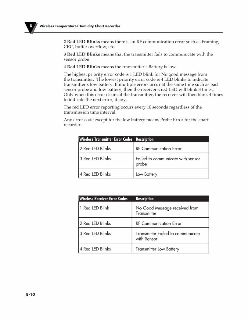
2 Red LED Blinks means there is an RF communication error such as Framing, CRC, buffer overflow, etc.3 Red LED Blinks means that the transmitter fails to communicate with the sensor probe4 Red LED Blinks means the transmitter’s Battery is low.The highest priority error code is 1 LED blink for No good message from the transmitter. The lowest priority error code is 4 LED blinks to indicate transmitter’s low battery. If multiple errors occur at the same time such as bad sensor probe and low battery, then the receiver’s red LED will blink 3 times. Only when this error clears at the transmitter, the receiver will then blink 4 times to indicate the next error, if any.The red LED error reporting occurs every 10 seconds regardless of the transmission time interval.Any error code except for the low battery means Probe Error for the chart recorder.
Wireless Transmitter Error Codes Description
2 Red LED Blinks RF Communication Error
3 Red LED Blinks Failed to communicate with sensor probe
4 Red LED Blinks Low Battery
Wireless Receiver Error Codes Description
1 Red LED Blink No Good Message received from Transmitter
2 Red LED Blinks RF Communication Error
3 Red LED Blinks Transmitter Failed to communicate with Sensor
4 Red LED Blinks Transmitter Low Battery
Wireless Temperature/Humidity Chart Recorder8
�8-10
Wireless Temperature/Humidity Chart Recorder 8
�8-11
8.5 Statement on FCC and CE Marking: 8.5.1 FCC - USA & Canada
FCC ID: WR3-CTXLPT IC: 8205A-CTXLPTThis device complies with Part 15 of the FCC rules. Operation is subject to the following two conditions: 1. This device may not cause harmful interference. 2. This device must accept any interference received, including interference that
may cause undesired operation
Changes or modifications not expressly approved by Omega Engineering, Inc. could void user’s authority to operate this equipment.
NOTE
This equipment has been tested and found to comply with the limits for a Class A digital device, pursuant to part 15 of the FCC Rules. These limits are designed to provide reasonable protection against harmful interference when the equipment is operated in a commercial environment. This equipment generates, uses, and can radiate radio frequency energy and, if not installed and used in accordance with the instruction manual, may cause harmful interference to radio communications. Operation of this equipment in a residential area is likely to cause harmful interference in which case the user will be required to correct the interference at his own expense.
8.5.2 International Usage & CE Marking (Pending)The Wireless CTXL (868 MHz mode) Series system components are CE marked and certified for use in several European countries. Please contact OMEGA for information on International Regulatory Compliance for each country.It is your (the user’s) responsibility to insure that these products are operated within the guidelines here in this manual and in conformance with all local or national regulations and laws.PRE-CAUTIONS - Transmitter Operation• Do not operate your wireless device outside the recommended environmental
limits specified in this manual.• Do not operate your wireless device in flammable or explosive environments.• Do not operate your wireless device in medical, nuclear, or other dangerous
applications.

• No co-location with other radio transmitters is allowed. By definition, co-location is when another radio device or it’s antenna is located within 20 cm of your wireless device and can transmit simultaneously.
• Do not install two wireless CTXL transmitters within 20 cm of each other.• Do not operate your wireless transmitter closer than 20 cm to nearby persons.PRE-CAUTIONS - Battery OperationYour wireless transmitter is supplied with one AA size 3.6V Lithium battery (Omega p/n OM-NOMAD-BATT). This battery is not re-chargeable. An optional 5V DC adapter is available (Omega p/n UNI-AC-100/240-5V) for permanent power installation.• Do not operate your wireless transmitter with any other battery other than
what is specified in this manual.• Do not place the battery in fire or heat the battery.• Do not solder to or short the battery terminals.• Do not disassemble or modify
the battery.• Dispose of your discharged batteries in accordance with your local, state, and
national laws.
Wireless Temperature/Humidity Chart Recorder8
�8-12

NOTES:
�8-13

NOTES:
�8-14

I
IndexI
Aac Adapter ............................................ 2-5ac Power Failure .................................. 2-5Alarms Deadband .............................. 4-3, 4 Enable/Disable ................ 2-10, 11 High ................................... 2-10, 11 Low .................................... 2-10, 11 Relay Outputs ........................ 2-11 Setting the Alarm ................... 2-10
BBatteries Compartment ....................... 1-3, 4 Installation/replacement ........ 2-4 Life ...................................... 2-4, 4-2 Indication/status ..................... 2-5Bulb replacement ................................ 1-2
CCarrying Slot . ................................... 1-3, 4Chart Door . ...................................... 1-2, 3 Icon ................................... 1-5, 2-15 Lights ..................................... 1-2, 3Chart Data Download ............................. 3-2, 3 Storage ....................................... 4-2Chart Paper Installing ................................... 2-6 Changing ................................... 2-6Chart Scale ..................................... 1-5, 2-6Chart Speed ................................... 1-5, 2-6CLOCK Key ................................ 1-5, 2-10 Battery back-up ........................ 4-2CONFIG Key ............................... 1-5, 2-10Control Panel Display ...................................... 1-5 Keypad ...................................... 1-5Cover for Feet & Stabilizing Arm ..... 2-2
D“D” Size Batteries ................................ 2-4Decorative Foot Cover ............. 1-2, 3, 2-3Display Backlite .................................. 1-3, 5 Configuration .................. 1-5, 2-10 Functions .................... 1-5, 2-10, 12 Mode ................................. 1-5, 2-12
Door Latch Button ......................... 1-2, 3 Lock (Key) ............................. 1-2, 3 Recorder ................................ 1-2, 3Dual Process Input ................... 1-3, 4, 4-5Dual Thermocouple Input ....1-4, 2-12, 4-4
EElectronic Data Storage ............................. 1-1 Lock/Unlock ............................ 1-5 Sensor ........................................ 4-3Extension Cable ................................. 2-13
FFoot Cover ................................. 1-2, 3, 2-3
HHigh Alarm ........................................ 2-10
IInput Range .......................... 1-1, 4-3, 4, 5 Open ........................................ 2-15 Out of Range ........................... 2-15Installing Batteries ..................................... 2-4 Chart Paper ............................... 2-6 Pens ............................................ 2-7
JJack, DC Power Input .................... . 1-2, 3Jamming Pen ...................................... 2-15
KKeypad .................................................. 1-5
LLatch Button for Door ..................... 1-2, 3LCD Display ........................................ 1-5LIGHT Key .................................... 1-5, 4-1Lock Key for Door ........................... 1-2, 3Lock/Unlock Keypad ......................... 1-5Low Alarm .................................. 1-5, 2-10Low Battery .......................................... 2-5

IndexI
MMaintenance ......................................... 5-1Memory ......................................... 3-2, 4-2MODE Key .................................. 1-5, 2-12Mounting Holes (Key Holes) ... 1-3, 4, 2-3
OOn/Off Power Switch ................. 1-5, 2-5
PPC Commands ................................. 3-1, 2PC Communication ............................. 3-1Pen Holders .......................................... 2-9Pen Jamming ...................................... 2-15Pen Replacing ...................................... 2-9Pen Rescaling .............................. 2-15, 3-2Power Battery ................................ 1-5, 2-4 DC Adapter .............................. 2-5 Failure ........................................ 2-5 Switch ........................................ 1-5Process Input ....................................... 4-5
RRelative Humidity .................... 1-2, 3, 4-3RelayAlarm Contact Closure ............... 2-11, 4-2 Wiring Diagram ..................... 2-11 Outputs ............................ 2-11, 4-2Remote Sensor ................................... 2-13Rescaling ...................................... 2-15, 3-2
SSCALE Key .................................... 1-5, 2-6Sensor Clip ......................................... 2-14SET Key ........................................ 1-5, 2-10Specifications ....................................... 4-1SPEED Key .................................... 1-5, 2-6Stabilizing Arm ................................... 2-2
TTemperature/Humidity Sensor ........ 4-3Thermocouple Input .................. 2-12, 4-4Time Set Arrow ............................ 1-2, 2-7Trouble Shooting ................................. 6-1
WWall Mounting ............................. 1-4, 2-3WHITE BOX Key ................. 1-5, 2-16, 4-2
I
II

OMEGA’s policy is to make running changes, not model changes, whenever an improvement is possible. This affords our customers the latest in technology and engineering.OMEGA is a trademark of OMEGA ENGINEERING, INC.© Copyright 2018 OMEGA ENGINEERING, INC. All rights reserved. This document may not be copied, photocopied, reproduced, translated, or reduced to any electronic medium or machine-readable form, in whole or in part, without the prior written consent of OMEGA ENGINEERING, INC.
FOR WARRANTY RETURNS, please have the following information available BEFORE contacting OMEGA:1. Purchase Order number under which the product
was PURCHASED,2. Model and serial number of the product under
warranty, and3. Repair instructions and/or specific problems relative to the product.
FOR NON-WARRANTY REPAIRS, consult OMEGA for current repair charges. Have the following information available BEFORE contacting OMEGA:1. Purchase Order number to cover the COST of the repair,2. Model and serial number of the product, and3. Repair instructions and/or specific problems relative to the product.
RETURN REQUESTS/INQUIRIESDirect all warranty and repair requests/inquiries to the OMEGA Customer Service Department. BEFORE RETURNING ANY PRODUCT(S) TO OMEGA, PURCHASER MUST OBTAIN AN AUTHORIZED RETURN (AR) NUMBER FROM OMEGA’S CUSTOMER SERVICE DEPARTMENT (IN ORDER TO AVOID PROCESSING DELAYS). The assigned AR number should then be marked on the outside of the return package and on any correspondence.The purchaser is responsible for shipping charges, freight, insurance and proper packaging to prevent breakage in transit.
WARRANTY/DISCLAIMEROMEGA ENGINEERING, INC. warrants this unit to be free of defects in materials and workmanship for a period of 25 months from date of purchase. OMEGA’s WARRANTY adds an additional one (1) month grace period to the normal two (2) year product warranty to cover handling and shipping time. This ensures that OMEGA’s customers receive maximum coverage on each product.If the unit malfunctions, it must be returned to the factory for evaluation. OMEGA’s Customer Service Department will issue an Authorized Return (AR) number immediately upon phone or written request. Upon examination by OMEGA, if the unit is found to be defective, it will be repaired or replaced at no charge. OMEGA’s WARRANTY does not apply to defects resulting from any action of the purchaser, including but not limited to mishandling, improper interfacing, operation outside of design limits, improper repair, or unauthorized modification. This WARRANTY is VOID if the unit shows evidence of having been tampered with or shows evidence of having been damaged as a result of excessive corrosion; or current, heat, moisture or vibration; improper specification; misapplication; misuse or other operating conditions outside of OMEGA’s control. Components in which wear is not warranted, include but are not limited to contact points, fuses, and triacs.OMEGA is pleased to offer suggestions on the use of its various products. However, OMEGA neither assumes responsibility for any omissions or errors nor assumes liability for any damages that result from the use of its products in accordance with information provided by OMEGA, either verbal or written. OMEGA warrants only that the parts manufactured by the company will be as specified and free of defects. OMEGA MAKES NO OTHER WARRANTIES OR REPRESENTATIONS OF ANY KIND WHATSOEVER, EXPRESSED OR IMPLIED, EXCEPT THAT OF TITLE, AND ALL IMPLIED WARRANTIES INCLUDING ANY WARRANTY OF MERCHANTABILITY AND FITNESS FOR A PARTICULAR PURPOSE ARE HEREBY DISCLAIMED. LIMITATION OF LIABILITY: The remedies of purchaser set forth herein are exclusive, and the total liability of OMEGA with respect to this order, whether based on contract, warranty, negligence, indemnification, strict liability or otherwise, shall not exceed the purchase price of the component upon which liability is based. In no event shall OMEGA be liable for consequential, incidental or special damages.CONDITIONS: Equipment sold by OMEGA is not intended to be used, nor shall it be used: (1) as a “Basic Component” under 10 CFR 21 (NRC), used in or with any nuclear installation or activity; or (2) in medical applications or used on humans. Should any Product(s) be used in or with any nuclear installation or activity, medical application, used on humans, or misused in any way, OMEGA assumes no responsibility as set forth in our basic WARRANTY/DISCLAIMER language, and, additionally, purchaser will indemnify OMEGA and hold OMEGA harmless from any liability or damage whatsoever arising out of the use of the Product(s) in such a manner.

M4098/0218
Where Do I Find Everything I Need for Process Measurement and Control?
OMEGA…Of Course!Shop online at omega.com
TEMPERATUREMU Thermocouple, RTD & Thermistor Probes, Connectors, Panels & Assemblies MU Wire: Thermocouple, RTD & ThermistorMU Calibrators & Ice Point ReferencesMU Recorders, Controllers & Process MonitorsMU Infrared Pyrometers
PRESSURE, STRAIN AND FORCEMU Transducers & Strain GagesMU Load Cells & Pressure GagesMU Displacement TransducersMU Instrumentation & Accessories
FLOW/LEVELMU Rotameters, Gas Mass Flowmeters & Flow ComputersMU Air Velocity IndicatorsMU Turbine/Paddlewheel SystemsMU Totalizers & Batch Controllers
pH/CONDUCTIVITYMU pH Electrodes, Testers & AccessoriesMU Benchtop/Laboratory MetersMU Controllers, Calibrators, Simulators & PumpsMU Industrial pH & Conductivity Equipment
DATA ACQUISITIONMU Communications-Based Acquisition SystemsMU Data Logging SystemsMU Wireless Sensors, Transmitters, & ReceiversMU Signal ConditionersMU Data Acquisition Software
HEATERSMU Heating CableMU Cartridge & Strip HeatersMU Immersion & Band HeatersMU Flexible HeatersMU Laboratory Heaters
ENVIRONMENTAL MONITORING AND CONTROLMU Metering & Control InstrumentationMU RefractometersMU Pumps & TubingMU Air, Soil & Water MonitorsMU Industrial Water & Wastewater TreatmentMU pH, Conductivity & Dissolved Oxygen Instruments