short communication corrosion resistance of super
TRANSCRIPT

Int. J. Electrochem. Sci., 13 (2018) 6190 – 6200, doi: 10.20964/2018.07.29
International Journal of
ELECTROCHEMICAL SCIENCE
www.electrochemsci.org
Short Communication
Corrosion Resistance of Super-Hydrophobic Coating on AZ31B
Mg Alloy
Zhengwei Song
1, Zhihui Xie
2,*, Lifeng Ding
1, Yike Zhang
1
1 Department of Chemistry and Chemical Engineering, Taiyuan Institute of Technology, Taiyuan
030024, Shanxi, China 2
Chemical Synthesis and Pollution Control Key Laboratory of Sichuan Province, China West Normal
University, Nanchong 637002, Sichuan, China *E-mail: [email protected]
Received: 31 March 2018 / Accepted: 8 May 2018 / Published: 5 June 2018
A super-hydrophobic coating was prepared on AZ31B Mg alloy in this paper. Electroless Ni-P coating
as the inner layer was deposited on the AZ31 substrate via an electroless planting process, and Cu was
electroplated as the intermediate layer. Then, the electroplating Ni method was employed to form the
micro/nano structure, and the super-hydrophobic coating was prepared after the composite coating
modified by stearic acid. The modified coating exhibited super-hydrophobic properties with a static
water contact angle of 155°. Potentiodynamic polarization and electrochemical impedance
spectroscopy (EIS) tests were conducted in 3.5 wt.% NaCl solution at room temperature. The test
results indicated that the corrosion resistance of AZ31 was improved significantly by this super-
hydrophobic coating. The super-hydrophobic samples had much more corrosion resistance in
comparison with freshly prepared samples.
Keywords: Corrosion resistance; Super-hydrophobic; Mg alloy
1. INTRODUCTION
Mg alloy, as the lightest alloy, has attracted industrial interest due to its high castability, low
density, bio-compatibility, and so on [1]. Magnesium alloys are intensively applied in the 3C,
automobile and clinical medicine fields. However, the high chemical reactivity of magnesium alloys
leads to poor corrosion resistance that limits its more widespread applications. Therefore, how to
enhance the corrosion resistance of magnesium and its alloys has been widely studied[2-6] .
Various surface treatment methods have been studied to enhance the corrosion resistance of
magnesium alloys[7-10]. Super-hydrophobic surfaces, with a water contact angle (CA) larger than
150°, have attracted particular interest of researchers due to the widespread potential applications in

Int. J. Electrochem. Sci., Vol. 13, 2018
6191
the fields of coatings, textiles, construction, and so on. Using super-hydrophobic surfaces as a new
method to improve the corrosion performance of metals has been reported in recent years[11-16].
Super-hydrophobic coatings have been successfully prepared on the surfaces of various engineering
materials, such as Fe, Al and Cu. This coating acts as a barrier layer that can reduce the portion of real
contact between the corrosive electrolyte and the metal surface[17]; hence, the corrosion resistance of
pre-treated substrate is better than before. As we know, the corrosion of Mg or Mg alloys usually
occurs in the presence of water, and it is significant to prepare an anticorrosion super-hydrophobic
surface on the Mg alloy surface for wide application of magnesium alloys.
To prepare super-hydrophobic coatings on metal surfaces, the following two conditions should
be met simultaneously[18]: first, a rough surface with hierarchical rough structures is required; second,
the material on the surface layer has to have low surface energy. Hence, super-hydrophobic surfaces
are often fabricated via two processes[19]: (1) creation of micro/nanometre-scale binary rough
structures on the surface; and (2) modification of an appropriate rough surface with low surface energy
materials.
In this paper, a simple method was designed for fabricating a super-hydrophobic coating on
AZ31B Mg alloy. The fabrication process of the super-hydrophobic surface mainly contains four steps:
electroless Ni-P coating, electrodeposition of Cu, electrodeposition of Ni, and modification. The
uniform electroless Ni-P coating as an inner layer can protect the substrate, and electrodeposition of
Cu provides a uniform distribution of the electric field for the Ni electrodeposition process. Then, the
process of Ni electrodeposition creates a micro/nanometre-scale binary rough structure surface. The
samples were then modified by immersing in 1 wt.% ethanol solution of stearic acid to reduce the
surface energy. The corrosion behaviour of this coating was also explored in this paper.
2. EXPERIMENT
2.1 Materials
Commercial AZ31B (wt.%: 3% Al, 1% Zn, 0.2% Mn, Fe < 0.005%, balanced Mg) was
purchased from Hong Di Metal Materials Co., Ltd (Dongguan, China). All chemical reagents were
obtained from Sinopharm Chemical Reagent Co., Ltd. and were used as received.
2.2 Specimen preparation
AZ31 Mg alloy with dimensions of 20×30×1.5 mm was ground with SiC paper with different
grit sizes (240, 600, 1200#) successively and then washed with distilled water and acetone step by step.
2.3 Coating preparation
The process flow and the main parameters for the pretreatment and electroless Ni-P coating
were introduced in our previous studies[20-22], and the conditions for electroplating Cu and

Int. J. Electrochem. Sci., Vol. 13, 2018
6192
electroplating Ni are listed in Table 1. The samples were cleaned thoroughly with deionized water as
quickly as possible between any two steps of the treatments.
Table 1. The bath composition and operation conditions of electroplating Cu and Ni
Process Composition Contents Conditions
Electroplating Cu Cu2P2O7 60 g·dm3
0.8~1 A·dm2
15 min
pH=9±0.5
45±2 °C
K4P2O7·3H2O 290 g·dm3
(NH4)3C6H5O7 25 g·dm3
Electroplating Ni NiCl∙6H2O 237 g·dm3
2 A·dm2
1-15 min
pH=4.0±0.5
60±2 °C
H3BO3 31 g·dm3
Ethylene diamine hydrochloride 140 g·dm3
2.4 Surface characterization
The morphology of the coatings was characterized by Field Emission Scanning Electron
Microscopy (FE-SEM) complemented by energy dispersive spectroscopy.
X-ray diffraction (XRD) with a Cu target was employed to characterize the crystal texture of
different coatings.
2.5 Electrochemical tests
The electrochemical workstation (PMC 2000, Princeton, USA) was used to research the
electrochemical corrosion behaviour of the samples. All electrochemical measurements were measured
by a three-electrode system at room temperature. The pre-treated samples as the working electrode
were embedded in epoxy resin, and the surface with a 10×10 mm2 area as the effective working side
was exposed. The Pt electrode and saturated calomel electrode were used as the reference and counter
electrodes. In general, 3.5 wt.% NaCl aqueous solution as the corrosive medium was used in all
electrochemical corrosion measurements.
Electrochemical impedance spectroscopy (EIS) and the electrochemical polarization curve
were tested to evaluate the extent of corrosion in 3.5 wt.% NaCl solution. EIS was tested at an open
circuit potential of 5 mV and AC amplitude in the frequency region from 100,000 to 0.01 Hz. The
electrochemical polarization curve was obtained at room temperature with a potential scanning rate of
1 mV·s1
from cathodic to anodic in the potential range from the open circuit potential to ±400 mV.
The tests were repeated three or more times to ascertain the creditability of the test results.

Int. J. Electrochem. Sci., Vol. 13, 2018
6193
2.6 Contact angle measurement
A contact angle meter was used to measure the water contact angles (CAs) at room
temperature. Five or more different points were measured to calculate the average value reported as the
CA value.
3. RESULTS AND DISCUSSION
3.1 The preparation of the nanometre-scale Ni coating
Figure 1 shows the morphology of the Ni-P and Cu coatings on AZ31B. The distribution of the
nodular structure on the Ni-P surface is uniform as shown in Figure 1, and the size of the nodular
structure is in the range of 5-10 μm. No cracks and pores were seen on both the nodular structural
surface and on the border of the two nodular structures. The surface became smoother through
electroplating Cu for 15 min (as shown in Figure 1b), and no visible nodular structure can be detected.
The uniform coating can provide a uniform electric field distribution for electroplating Ni. After 20
cycles of the thermal shock experiment according to ASTM B733-04, no blistering, crinkling, or
breakage was observed at 4 times magnification[23]. The result shows that the adhesion of the Ni-P/Cu
coating is excellent. In the next process of electroplating, the compact and uniform coating of Ni-P/Cu
could protect the substrate from corrosion. The CAs of Ni-P and Cu are about 52° and 70°, which
indicated that the Ni-P and Cu coatings are hydrophilic coatings.
Figure 1. The morphology of electroless Ni-P and electroplated Cu coatings: a: Ni-P; b: Cu

Int. J. Electrochem. Sci., Vol. 13, 2018
6194
Figure 2 shows the morphology of the Ni coatings electroplated on the Cu surface for 1, 5, 10,
and 15 min, respectively. After electroplating Ni, more rough pinecone-like structures can be formed
on the surface of Cu. The pinecone-like structures are mainly composed of scales with a size
distribution ranging from 50–300 nm as shown in Figure 2b. As the plating time increased from 1 min
to 15 min, the pinecone structures grow larger as the gap between the pinecones becomes narrow. The
substrate becomes better covered after 15 min of plating.
Figure 2. The morphology of the Ni coating electroplated on the Ni-P/Cu surface after different
plating times: a: 1 min; b: 5 min; c: 10; d: 15 min
Figure 3 compares the XRD patterns of the Mg alloy, pure Ni, Ni-P coating, and stearic acid-
modified Ni-P/Cu/Ni composite coating. The Mg alloy is mainly composed of Mg and intermetallic
compounds Mg17Al12. The Ni-P coating shows a wide peak of Ni (111), which is evidence of an
amorphous structure. The amorphous structure of the Ni-P coating exhibits good corrosion resistance.
After electrodeposition of Ni on Cu, it is clear that the three diffraction peaks of Ni at 2θ = 44.51°,
52.00° and 76.57° correspond to the characteristic peaks of the Ni(111), Ni(200) and Ni(220) planes of
the face-centred cubic Ni crystals, respectively [24]. The other three peaks at 2θ values of 43.64°,
50.80°, and 74.42° corresponding to the (111), (200), and (220) planes of copper were observed and
compared with the standard powder diffraction card of JCPDS, copper file No. 04–0836[25]. The
relative intensity of the Ni(200) peak in the electrodeposited Ni coating was weaker than that in pure
Ni, and this result indicated that the Ni(200) crystal plane was covered by other crystal planes in the

Int. J. Electrochem. Sci., Vol. 13, 2018
6195
process of electrodeposition[26], which can also explain why pinecone-like structures of the Ni coating
were formed.
20 30 40 50 60 70
0
500
1000
1500
2000
2500
3000
Ni
2
kC
nt
electroplating Ni
Pure Ni
eletroplating Cu
electroless Ni
Cu
Ni
CuNi
Cu
Figure 3. XRD patterns of the pure Ni, Ni-P coating, electroplated Cu coating and Ni-P/Cu/Ni
composite coating
3.2 CAs of the coating
Figure 4 shows the CA change in water droplets on Ni-P/Cu/Ni and stearic acid-modified Ni-
P/Cu/Ni composite coating. The Cu coating has a hydrophilic character with a CA of about 70°. As the
roughness of the Ni coating increases with plating time, the contact angles will decrease with Ni
plating time, and CA becomes 0° after plating Ni for 5 min. The results were consistent with Wenzel’s
conclusion. According to the Wenzel model[27], for a hydrophilic surface, roughness increases the
surface area of the solid, which geometrically enhances hydrophilicity.
ccos cosr (1)
where r is the roughness defined as the ratio between the real and projected solid liquid contact
areas and θc and θ are the contact angles on the rough and smooth surfaces, respectively. A
hierarchically micro/nano-structured Ni-P/Cu/Ni coating was prepared on the Mg alloy. Hence, the
first condition was reached for the formation of a hydrophobic coating. After modifying with stearic
acid, the CAs of the composite coating increase gradually from 0 to 155°. It is well-known that stearic
acid contains a carboxyl group and a long alkyl chain, and Ni coating has some hydroxyl groups. In the
process of modification, the reaction between a carboxyl group and a hydroxyl group takes off a
molecule of water, and then the long alkyl chain is modified on the surface of the Ni coating. The
second condition is then reached for the formation of a hydrophobic coating, according to the Cassie-
Baxter model[28], and the hydrophobicity of the hydrophobic coating increases with the surface
roughness because air is trapped in the hierarchical structure.
Int. J. Electrochem. Sci., Vol. 13, 2018
6196
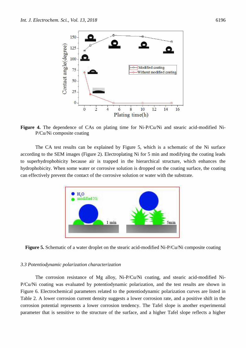
Figure 4. The dependence of CAs on plating time for Ni-P/Cu/Ni and stearic acid-modified Ni-
P/Cu/Ni composite coating
The CA test results can be explained by Figure 5, which is a schematic of the Ni surface
according to the SEM images (Figure 2). Electroplating Ni for 5 min and modifying the coating leads
to superhydrophobicity because air is trapped in the hierarchical structure, which enhances the
hydrophobicity. When some water or corrosive solution is dropped on the coating surface, the coating
can effectively prevent the contact of the corrosive solution or water with the substrate.
Figure 5. Schematic of a water droplet on the stearic acid-modified Ni-P/Cu/Ni composite coating
3.3 Potentiodynamic polarization characterization
The corrosion resistance of Mg alloy, Ni-P/Cu/Ni coating, and stearic acid-modified Ni-
P/Cu/Ni coating was evaluated by potentiodynamic polarization, and the test results are shown in
Figure 6. Electrochemical parameters related to the potentiodynamic polarization curves are listed in
Table 2. A lower corrosion current density suggests a lower corrosion rate, and a positive shift in the
corrosion potential represents a lower corrosion tendency. The Tafel slope is another experimental
parameter that is sensitive to the structure of the surface, and a higher Tafel slope reflects a higher

Int. J. Electrochem. Sci., Vol. 13, 2018
6197
resistance of the electrode reaction in the Tafel region. For the unmodified coating and modified
coating, the corrosion current density icorr was decreased by one or two orders of magnitude after
modification. A positive shift of 1150 mV in Ecorr was observed compared with the Mg alloy substrate.
For the modified sample, the anode polarization slope (ba) value was higher than for the unmodified
coating and Mg alloy, and an obvious passivation region was observed in the polarization curve, which
suggested that a passivation film may have formed on the surface of the sample during the corrosion
process[29]. The previous test results indicated that more air can be trapped on the super-hydrophobic
coating surface, the air cushion was formed between coating and NaCl solution when the sample
immersion in NaCl solution, that led to small contact area of surface with NaCl solution and
passivation film easily formed on the modified coating surface compared with unmodified coating.
Thus the modified composite coating has lower icorr and higher E and ba than the unmodified coating.
The results were consistent with the conclusions of the other previous work in this area [29, 30]. It
indicated that the coating exhibits a lower corrosion tendency and corrosion rate after modification by
stearic acid.
Figure 6. Potentiodynamic polarization curves of Mg alloy, Ni-P/Cu/Ni coating and stearic acid-
modified Ni-P/Cu/Ni coating in 3.5 wt.% NaCl solution
Table 2. The values of the electrochemical parameters obtained from the polarization curves in Figure
6
Specimens Mg alloy Ni-P/Cu/Ni coating Ni-P/Cu/Ni/stearic acid-modified coating
Ecorr/VvsSCE 1.52 0.38 0.37
icorr/(A·cm2
) 3.66×10⁴
1.07×10⁵
4.02×10⁶
ba/(mV·dec1
) 119.34 416.32 887.61
bc/(mV·dec1
) 156.52 431.49 785.94
3.4 EIS characteristics
EIS was also employed to evaluate the protective performances of the samples. The test results
are shown in Figure 7. The Nyquist plots and Bode plots are presented in Figures 7(a) and (b),
Int. J. Electrochem. Sci., Vol. 13, 2018
6198
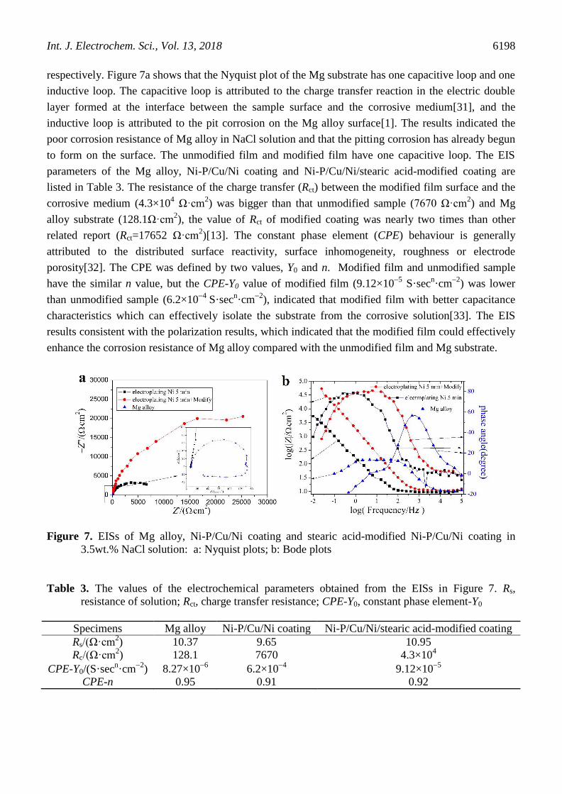
respectively. Figure 7a shows that the Nyquist plot of the Mg substrate has one capacitive loop and one
inductive loop. The capacitive loop is attributed to the charge transfer reaction in the electric double
layer formed at the interface between the sample surface and the corrosive medium[31], and the
inductive loop is attributed to the pit corrosion on the Mg alloy surface[1]. The results indicated the
poor corrosion resistance of Mg alloy in NaCl solution and that the pitting corrosion has already begun
to form on the surface. The unmodified film and modified film have one capacitive loop. The EIS
parameters of the Mg alloy, Ni-P/Cu/Ni coating and Ni-P/Cu/Ni/stearic acid-modified coating are
listed in Table 3. The resistance of the charge transfer (Rct) between the modified film surface and the
corrosive medium (4.3×10⁴ Ω·cm
2) was bigger than that unmodified sample (7670 Ω·cm
2) and Mg
alloy substrate (128.1Ω·cm2), the value of Rct of modified coating was nearly two times than other
related report (Rct=17652 Ω·cm2)[13]. The constant phase element (CPE) behaviour is generally
attributed to the distributed surface reactivity, surface inhomogeneity, roughness or electrode
porosity[32]. The CPE was defined by two values, Y0 and n. Modified film and unmodified sample
have the similar n value, but the CPE-Y0 value of modified film (9.12×10⁵
S·secn·cm
2) was lower
than unmodified sample (6.2×10⁴
S·secn·cm
2), indicated that modified film with better capacitance
characteristics which can effectively isolate the substrate from the corrosive solution[33]. The EIS
results consistent with the polarization results, which indicated that the modified film could effectively
enhance the corrosion resistance of Mg alloy compared with the unmodified film and Mg substrate.
Figure 7. EISs of Mg alloy, Ni-P/Cu/Ni coating and stearic acid-modified Ni-P/Cu/Ni coating in
3.5wt.% NaCl solution: a: Nyquist plots; b: Bode plots
Table 3. The values of the electrochemical parameters obtained from the EISs in Figure 7. Rs,
resistance of solution; Rct, charge transfer resistance; CPE-Y0, constant phase element-Y0
Specimens Mg alloy Ni-P/Cu/Ni coating Ni-P/Cu/Ni/stearic acid-modified coating
Rs/(Ω·cm2) 10.37 9.65 10.95
Rc/(Ω·cm2) 128.1 7670 4.3×10
4
CPE-Y0/(S·secn·cm
2) 8.27×10
6 6.2×10
4 9.12×10
5
CPE-n 0.95 0.91 0.92

Int. J. Electrochem. Sci., Vol. 13, 2018
6199
4. CONCLUSIONS
A super-hydrophobic composite coating was prepared on AZ31B via electroless Ni-P coating,
electroplating Cu, electroplating Ni and modification with stearic acid. The micro/nanometre-scale
binary rough structures surface was formed via electroless Ni-P coating for 90 min, electroplating Cu
for 15 min, and electroplating Ni for 5 min. The CA of the coating was about 155° after the prepared
coating was modified in 1% stearic acid ethanol solution for 2 h. The corrosion resistance of the super-
hydrophobic composite coating was characterized by potentiodynamic polarization and EIS. The
potentiodynamic polarization results showed that the super-hydrophobic composite coating had lower
icorr (4.02×10⁶
A·cm2
) and higher E (0.37 VvsSCE) than the unmodified coating. The EIS results
showed that the resistance of the charge transfer between the modified film surface and the corrosive
medium was bigger than that between the unmodified film surface and the corrosive medium. All of
the test results indicated that the modified composite coating exhibited higher corrosion resistance than
the unmodified coating.
ACKNOWLEDGEMENT
This study are jointly funded by the National Natural Science Foundation of China (51501157,
51604180), the Fundamental Research Funds of China West Normal University (17B005), and the
Chemical Synthesis and Pollution Control Key Laboratory of Sichuan Province (CSPC2014-4-2).
References
1. Z. Song, Z. Xie, G. Yu, B. Hu, X. He, and X. Zhang, J. Alloys Compd., 623(2015) 274-281.
2. T. Xiang, S. Ding, C. Li, S. Zheng, W. Hu, J. Wang, and P. Liu, Mater. Des., 114(2017) 65-72.
3. N.V. Phuong, M. Gupta, and S. Moon, Prog. Org. Coat., 102, Part B(2017) 144-150.
4. A.D. Forero López, I.L. Lehr, and S.B. Saidman, J. Alloys Compd., 702(2017) 338-345.
5. L.-Y. Cui, S.-D. Gao, P.-P. Li, R.-C. Zeng, F. Zhang, S.-Q. Li, and E.-H. Han, Corros. Sci.,
118(2017) 84-95.
6. Y. Zhang, S. Tang, J. Hu, and T. Lin, Corros. Sci., 111(2016) 334-343.
7. J. Zhang, C. Gu, Y. Tong, W. Yan, and J. Tu, Adv. Mater. Interfaces, 3(2016) 1500694.
8. J.A. Fairfield, C.G. Rocha, C. O'Callaghan, M.S. Ferreira, and J.J. Boland, Nanoscale, 8(2016)
18516-18523.
9. F. Zhang, L. Zhao, H. Chen, S. Xu, D.G. Evans, and X. Duan, Angew. Chem. Int. Ed. Engl.,
47(2008) 2466-9.
10. C. Gu, J. Lian, J. He, Z. Jiang, and Q. Jiang, Surf. Coat. Technol., 200(2006) 5413-5418.
11. D. Zang, R. Zhu, W. Zhang, X. Yu, L. Lin, X. Guo, M. Liu, and L. Jiang, Adv. Funct. Mater.,
27(2017) 1605446.
12. Q. Liu, D. Chen, and Z. Kang, ACS Appl. Mater. Interfaces, 7(2015) 1859-67.
13. Y. Liu, X. Yin, J. Zhang, S. Yu, Z. Han, and L. Ren, Electrochim. Acta, 125(2014) 395-403.
14. Z. Wang, Q. Li, Z. She, F. Chen, and L. Li, J. Mater. Chem., 22(2012) 4097.
15. F. Tian, A. Hu, M. Li, and D. Mao, Appl. Surf. Sci., 258(2012) 3643-3646.
16. H. Ogihara, T. Katayama, and T. Saji, J. Mater. Chem., 21(2011) 14890.
17. R. Gan, D. Wang, Z.H. Xie, and L. He, Corros. Sci., 123 (2017) 147-157.
18. Z.P. Zhang, Y.H. Qi, Y. Zhang, G.K. Mo, and J.Z. Wang, Mater. Sci. Forum, (2010) 1900-1903.
19. J.L. Song, W.J. Xu, Y. Lu, X. Liu, and J. Sun, Mater. Corros., 64(2013) 979-987.
20. J. Zhao, X. Xie, and C. Zhang, Corros. Sci., 114(2017) 146-155.

Int. J. Electrochem. Sci., Vol. 13, 2018
6200
21. D. Li, F. Chen, Z.H. Xie, S. Shan, and C.J. Zhong, J. Alloys Compd., 705(2017) 70-78.
22. Z.H. Xie, F. Chen, S.R. Xiang, J.L. Zhou, Z.W. Song, and G. Yu, J. Electrochem. Soc., 162(2015)
D115-D123.
23. D. Yan, G. Yu, B. Hu, J. Zhang, Z. Song, and X. Zhang, J. Alloys Compd., 653(2015) 271-278.
24. Z. She, Q. Li, Z. Wang, L. Li, F. Chen, and J. Zhou, Chem. Eng. J., 228(2013) 415-424.
25. T. Theivasanthi and M. Alagar, Epl, 53(2010) 169-175.
26. Z. Chen, F. Tian, A. Hu, and M. Li, Surf. Coat. Technol., 231(2013) 88-92.
27. R.N. Wenzel, Ind.eng.chem, 28(1936) 988-994.
28. A.B.D. Cassie, Discuss. Faraday Soc., 3(1948) 11-16.
29. Y. Wang, Z. Gu, Y. Xin, N. Yuan, and J. Ding, Colloids Surf. Physicochem. Eng. Aspects,
538(2018) 500-505.
30. Y. Zhong, J. Hu, Y. Zhang, and S. Tang, Appl. Surf. Sci., 427(2018) 1193-1201.
31. H. Zhao, S. Cai, Z. Ding, M. Zhang, Y. Li, and G. Xu, Rsc Adv., 5(2015) 24586-24590.
32. Y. Song, D. Shan, R. Chen, and E.-H. Han, Corros. Sci., 51(2009) 1087-1094.
33. Z. Song, G. Yu, Z. Xie, B. Hu, X. He, and X. Zhang, Surf. Coat. Technol., 242(2014) 83-91
© 2018 The Authors. Published by ESG (www.electrochemsci.org). This article is an open access
article distributed under the terms and conditions of the Creative Commons Attribution license
(http://creativecommons.org/licenses/by/4.0/).