short form catalog - anatech electronics
TRANSCRIPT
CONTACT US TODAY! [email protected] 973.772.4242ANATECH ELECTRONICS, INC. 70 Outwater Lane, Garfield, New Jersey 07026 anatechelectronics.com
SHORT FORM CATALOG
MG007 ANATECH_FINAL_Layout 1 7/28/14 4:42 PM Page 1

2
ABOUT USAnatech Electronics, Inc. (AEI), is a privately-held, ISO9001 Cer-tified company founded in January of 1990 that focuses on thedesign and manufacturing of RF and microwave filters and re-lated products. Our broad array of products is used in commer-cial, aerospace and defense, and industrial applicationsthroughout the world. We specialize in rapidly responding to cus-tomer needs, creating cost-effective solutions to meet them.
APPLICATIONS WE SERVEOur products are used in a broad array of applications, such as:Wireless communication systemsDefense electronic systems (electronic warfare, electroniccountermeasures, radar, and communications)Public safetyMedical systemsGPS navigation systemsSatellite communications terminalsIEEE 802.11a/b/g/n WiFi systemsPoint-to-point microwave links
… And many others.
PRODUCTS FOR DEFENSE APPLICATIONSThe aerospace and defense industry is one of AIE’s primary mar-kets, and it has developed the capabilities, facilities, and qualitycontrol procedures required by defense customers. AnatechElectronics (AEI) is an ISO9001-2008 certified company, and alsofollows the guidelines of MIL-STD-45208A and MIL-F-18327.AIE is a registered supplier with Aerospace Corp., L-3 Commu-nications, BAE Systems, Boeing, General Dynamics, Harris Corp.,Lockheed Martin, NAVSUP, Northrop Grumman, Peterson AirForce Base, Raytheon, Rockwell Collins, SPAWAR, and other de-fense contractors.
CAPABILITIES AND FACILITIESAEI’s capabilities include a technical staff with many decades ofexperience in RF and microwave design, which is supported byhighly-qualified sales engineers, administrators, quality control,marketing, IT, and accounting staff. The company maintains afull manufacturing facility, geared for low and high volume man-ufacturing and testing.
CONTENTSTANDARD & CUSTOM RF FILTERS
BANDPASS FILTERS
Cavity Bandpass & Ceramic Bandpass ............... 3Connectorized Ceramic Bandpass ...................... 3Surface Mount LC Bandpass .............................. 4Crystal Bandpass ............................................... 4LC Bandpass & Saw Bandpass .......................... 4
DUPLEXERSCavity Duplexers ................................................ 5Ceramic Duplexers ............................................ 5LC Duplexers ..................................................... 5SAW Duplexers .................................................. 6Connectorized Ceramic Duplexers ..................... 6
BANDPASS FILTERSBandpass-LNA .................................................. 6Duplexers-LNA .................................................. 7
Multi-band Cavity Multiplexers/Combiners ......... 7Multi-band Ceramic Multiplexers/Combiners ..... 7LC Lowpass ....................................................... 8Surface-Mount LC Lowpass ............................... 8LC Highpass ...................................................... 8Surface-Mount LC Highpass .............................. 9LC Bandstop ...................................................... 9 Helical Filters Series .......................................... 10Key Definitions .................................................. 11More About AEI .................................................. 14Ordering ............................................................ 15
Bring us your challenge, we’ll provide the answer!
EMAIL: [email protected] HONE: (973) 772-4242
WEB: www.anatechelectronics.com
MG007 ANATECH_FINAL_Layout 1 7/28/14 4:42 PM Page 2

3
AEI BANDPASS FILTERSAnatech Electronics (AEI) bandpass filters are available from 10 kHz to 40 GHz with 2 to 15 sections with bandwidths rangingfrom 0.5% to 100%. The most commonly used topology types are Chebyshev, Butterworth, Elliptic and other special topologiesare also used depending on the requirements. Our designs are optimized to reduce package size as much as possible, whilekeeping the insertion loss to a minimum, and meet the electrical requirements with a reasonable margin. Our proprietary designtechniques allow us to design very complex filters for a broad range of bandwidths from very narrow to very wide, with excellentperformance, such as very sharp passband to stopband transition, high power handling, and very low insertion loss. The filters canbe optimized for other performance parameters such as group delay variation, amplitude matching, and phase matching.
CAVITY BANDPASS Anatech Electronics cavity bandpass filters are available in a wide range of frequencies, power levels,bandwidths, and rejection. The resonators and cavities are silver plated for low RF resistivity, in order toachieve low insertion loss and high selectivity. Filter size depends on performance requirements, frequencyof operation, RF power handling, insertion loss, and number of sections. AEI uses the best topology requiredto achieve the requirements. The cavity bandpass filters range in length from 1 in. to more than 18 in., dependingon number of sections, insertion loss, power handling, and center frequency. Packaging and mounting options include sur-face mount, connectorized, printed circuit board mount, and drop-in. AEI offers a broad range of customization possibilities,from electrical characteristics to size, mounting, and weatherization.
CERAMIC BANDPASS AEI’s ceramic bandpass filters deliver extremely high performance and reliability and serve a broad array of applicationsfrom 400 to 6500 MHz. Their size depends on the dielectric constant of the ceramic resonator (typically between 30and 90), and the lower the dielectric constant the larger the resonator and the better the temperature coeffi-cient (and vice versa). Ceramic bandpass filters can be made from discrete ceramic resonators or asa single piece of ceramic material called a “monoblock” structure. Monoblock ceramic filters are bestsuited for high-volume applications in which their higher manufacturing cost can be amortized overa large number of devices. Other than reduced size, monoblock ceramic filters have performancenearly identical to that of their discrete counterpart.
CONNECTORIZED CERAMIC BANDPASS Connectorized ceramic bandpass filters have the same performance and characteristics as their SMT ceramicbandpass filter counterparts except that they are conveniently enclosed inside a connectorized metalenclosure. This makes them usable in both indoor and outdoor applications when housed in a weather-proof enclosure, and they can withstand extreme environmental conditions. Connectorized ceramic filterscan be fitted with SMA, Type-N, SMC, SMB, F, or TNC connectors in any combination.
FrequencyRange(MHz)
3dB Bandwith
(%)Nunber
of SectionsVSWR (typ.)
Impedance(Ohms)
Maximum power (W)
Package styles
Operating temp. (deg.C) Shock Vibration
20-40000 0.3 to morethan 100
2 to 15 1.5:1 50 500 Connectorized PCMount, Drop In
-55 to +85 30G, 11ms 20G, 5-200Hz
FrequencyRange(MHz)
3dB Bandwith
(%)Nunber
of SectionsVSWR (typ.)
Impedance(Ohms)
Maximum power (W)
Package styles
Operating temp. (deg.C) Shock Vibration
400-6500 2 to 35 2 to 8 1.5:1 50 5 to 8 Surface Mount -55 to +85 20G, 11ms 10G, 5-200Hz
FrequencyRange(MHz)
3dB Bandwith
(%)Nunber
of SectionsVSWR (typ.)
Impedance(Ohms)
Maximum power (W)
Package styles
Operating temp. (deg.C) Shock Vibration
400 to 6500 2 to 35 2 to 8 1.5:1 50 5 to 8 Connectorized -55 to +85 20G, 11ms 10G, 5-200Hz
MG007 ANATECH_FINAL_Layout 1 7/28/14 4:42 PM Page 3
4
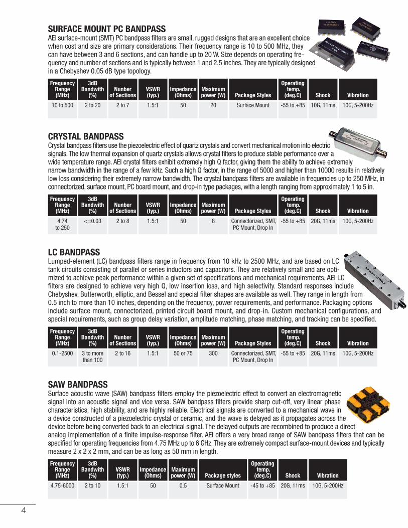
SURFACE MOUNT PC BANDPASS AEI surface-mount (SMT) PC bandpass filters are small, rugged designs that are an excellent choicewhen cost and size are primary considerations. Their frequency range is 10 to 500 MHz, theycan have between 3 and 6 sections, and can handle up to 20 W. Size depends on operating fre-quency and number of sections and is typically between 1 and 2.5 inches. They are typically designedin a Chebyshev 0.05 dB type topology.
CRYSTAL BANDPASSCrystal bandpass filters use the piezoelectric effect of quartz crystals and convert mechanical motion into electricsignals. The low thermal expansion of quartz crystals allows crystal filters to produce stable performance over awide temperature range. AEI crystal filters exhibit extremely high Q factor, giving them the ability to achieve extremelynarrow bandwidth in the range of a few kHz. Such a high Q factor, in the range of 5000 and higher than 10000 results in relativelylow loss considering their extremely narrow bandwidth. The crystal bandpass filters are available in frequencies up to 250 MHz, inconnectorized, surface mount, PC board mount, and drop-in type packages, with a length ranging from approximately 1 to 5 in.
LC BANDPASS Lumped-element (LC) bandpass filters range in frequency from 10 kHz to 2500 MHz, and are based on LCtank circuits consisting of parallel or series inductors and capacitors. They are relatively small and are opti-mized to achieve peak performance within a given set of specifications and mechanical requirements. AEI LCfilters are designed to achieve very high Q, low insertion loss, and high selectivity. Standard responses includeChebyshev, Butterworth, elliptic, and Bessel and special filter shapes are available as well. They range in length from0.5 inch to more than 10 inches, depending on the frequency, power requirements, and performance. Packaging optionsinclude surface mount, connectorized, printed circuit board mount, and drop-in. Custom mechanical configurations, andspecial requirements, such as group delay variation, amplitude matching, phase matching, and tracking can be specified.
SAW BANDPASSSurface acoustic wave (SAW) bandpass filters employ the piezoelectric effect to convert an electromagneticsignal into an acoustic signal and vice versa. SAW bandpass filters provide sharp cut-off, very linear phasecharacteristics, high stability, and are highly reliable. Electrical signals are converted to a mechanical wave ina device constructed of a piezoelectric crystal or ceramic, and the wave is delayed as it propagates across thedevice before being converted back to an electrical signal. The delayed outputs are recombined to produce a directanalog implementation of a finite impulse-response filter. AEI offers a very broad range of SAW bandpass filters that can bespecified for operating frequencies from 4.75 MHz up to 6 GHz. They are extremely compact surface-mount devices and typicallymeasure 2 x 2 x 2 mm, and can be as long as 50 mm in length.
FrequencyRange(MHz)
3dB Bandwith
(%)Nunber
of SectionsVSWR (typ.)
Impedance(Ohms)
Maximum power (W) Package Styles
Operating temp. (deg.C) Shock Vibration
10 to 500 2 to 20 2 to 7 1.5:1 50 20 Surface Mount -55 to +85 10G, 11ms 10G, 5-200Hz
FrequencyRange(MHz)
3dB Bandwith
(%)Nunber
of SectionsVSWR (typ.)
Impedance(Ohms)
Maximum power (W) Package Styles
Operating temp. (deg.C) Shock Vibration
4.74to 250
<=0.03 2 to 8 1.5:1 50 8 Connectorized, SMT,PC Mount, Drop In
-55 to +85 20G, 11ms 10G, 5-200Hz
FrequencyRange(MHz)
3dB Bandwith
(%)Nunber
of SectionsVSWR (typ.)
Impedance(Ohms)
Maximum power (W) Package Styles
Operating temp. (deg.C) Shock Vibration
0.1-2500 3 to morethan 100
2 to 16 1.5:1 50 or 75 300 Connectorized, SMT,PC Mount, Drop In
-55 to +85 20G, 11ms 10G, 5-200Hz
FrequencyRange(MHz)
3dB Bandwith
(%)VSWR (typ.)
Impedance(Ohms)
Maximum power (W) Package styles
Operating temp. (deg.C) Shock Vibration
4.75-6000 2 to 10 1.5:1 50 0.5 Surface Mount -45 to +85 20G, 11ms 10G, 5-200Hz
MG007 ANATECH_FINAL_Layout 1 7/28/14 4:42 PM Page 4

5
AEI DUPLEXERSAnatech Electronics (AEI) duplexers are custom products that combine receive and transmit channels to allow a single antennato be used, as well as splitting the received RX, and TX signals. They are available with operating frequencies of 1 MHz to 17 GHzand in 2 to 15 sections with isolation up to 100 dB, and RF power handling ability of 500 W or more. Technologies used are cavity,ceramic, LC, and SAW. Duplexers designed specifically for commercial and military wireless applications, such as GSM, PCS,WCDMA, LTE, and Wi-Fi, as well as multi-band applications are available in custom and standard models. AEI will match the spec-ification, and form-fit factor of duplexers from other manufacturers as well. AEI duplexers can be manufactured with SMA, Type-N, BNC, TNC, SMC, SMB, 7/16 connectors. Duplexers are also available in surface mount, PC mount, and drop-in style enclosures.Special packaging and connectors can also be specified.
CAVITY DUPLEXERS AEI cavity duplexers are available with 2 to 18 resonators and bandwidths ranging from 3% to 100%.The resonator and cavity are silver plated for low insertion loss and high selectivity. The cavity duplexersrange in frequencies from 20 MHz to 20 GHz, and can handle RF power inputs up to 500 W. Duplexers areavailable that can withstand hostile environments encountered in outdoor installations. Standard designsuse a 0.05-dB Chebyshev response and other response types such as Butterworth and elliptic are also useddepending on the performance. They range in length from 1.5 to more than 10 in. depending on the insertion loss, powerhandling, and center frequency requirements. The duplexers are available in surface mount, connectorized, PC mount, drop-in,as well as special configurations specified by the requirements.
CERAMIC DUPLEXERS AEI ceramic duplexers are fabricated with the highest quality ceramic material with a dielectric constantbetween 30 to more than 90. The dielectric constant is chosen based on size and performance re-quirements. The lower dielectric constant ceramic material will result in higher Q factors, high tem-perature stability, and large size, while the high dielectric constant material will result in lowerperformance, lower temperature stability, but very small size. Their high Q factor leads to higher per-formance in a minimal size with lower insertion loss and better selectivity. AEI ceramic duplexers areavailable in surface mount packages, as well as connectorized packages available on request. The size of a ceramic duplexer de-pends on the frequency range, insertion loss, and selectivity of the filter and can range in length from 10 to 80 mm.
LC DUPLEXERS AEI LC duplexers are manufactured using inductors and capacitors with a high Q factor thatresults in low insertion loss and high selectivity. LC duplexers can be designed to operate from100 kHz up to 2500 MHz and can handle up to 40 W. Standard designs use the 0.05-dB Cheby-shev Butterworth, elliptic, and Bessel response topology, and other special shapes using inhouse developed design tools. AEI LC duplexers range in length from 1 to more than 18 in. dependingon frequency of operation, power handling, insertion loss, and other parameters. The LC duplexers are available in connec-torized, surface mount, PC mount, drop-in, and any other special configurations required by the customer.
FrequencyRange(MHz)
3dB Bandwith
(%)Nunber
of SectionsIsolation(dB)
VSWR (typ.)
Impedance(Ohms)
Maximum power (W) Package Styles
Operating temp. (deg.C) Vibration
20 to 40 0.7 to 50 2 to 13 30 to 120 1.5:1 50 500 Connectorized, Drop-in
-55 to +85 20G, 5-200Hz
FrequencyRange(MHz)
3dB Bandwith
(%)Nunber
of SectionsIsolation(dB)
VSWR (typ.)
Impedance(Ohms)
Maximum power (W) Package Styles
Operating temp. (deg.C) Vibration
400 to 6500 2 to 35 2 to 8 25 to 80 1.5:1 50 5 to 8 Surface Mount -45 to +85 10G, 5-200Hz
FrequencyRange(MHz)
3dB Bandwith
(%)Nunber
of SectionsIsolation(dB)
VSWR (typ.)
Impedance(Ohms)
Maximum power (W) Package Styles
Operating temp. (deg.C) Vibration
0.1 to 2500 2 to 100 2 to 10 30 to 120 1.5:1 50 or 75 300 Connectorized, PCMount, Drop-in, SMT
-55 to +85 20G, 5-200Hz
MG007 ANATECH_FINAL_Layout 1 7/28/14 4:42 PM Page 5

6
SAW DUPLEXERS Surface Acoustic Wave (SAW) duplexers provide high stability and sharp rejection characteristics in acompact surface-mount package ranging in size from 3 x 3 x 2 mm to 30 x 15 x 2.5 mm. Insertionloss ranges from 1.8 dB to 6 dB with isolation ranging from 20 dB to more than 50 dB. The maximumRF power of a SAW duplexer is about 1 W.
CONNECTORIZED CERAMIC DUPLEXERS Connectorized ceramic duplexers have the same electrical characteristics as their SMT ceramic duplexercounterparts but are housed in a connectorized metal enclosure. They can also be a lower-cost alternativeto cavity duplexers in low-power applications. Connectorized duplexers have the same functionality as theirSMT counterparts and are used to duplex a receive/transmit communication system, combine signals to useonly one antenna in transceivers, and in many other wireless applications. Connectorized ceramic duplexers have op-erating frequencies between 400 MHz and 6 GHz. Their enclosure size depends on the size of the ceramic duplexer within themand is typically between 0.75 and 3.5 in. Available connectors can be SMA, Type-N, TNC, or F in any combination. Special con-nectors are available per customer requirement.
BANDPASS-LNA Anatech Electronics (AEI) bandpass-LNA filters and duplexer-LNA filters combine a bandpassfilter or duplexer with a low-noise amplifier, bringing two essential components together ina compact, ruggedized package that is well suited for military applications from C thru Kuband (2 to 20 GHz). Some of our duplexer-LNA filters are tailored for satellite communicationsapplications and feature increased dynamic range and receive sensitivity. LNA amplification range is up to 40 dB and noisefigure is between 2 to 4 dB. Size depends on the operating frequency, selectivity, isolation (duplexer only), amplification, andpower levels. Customized designs are welcome.
FrequencyRange(MHz)
3dB Bandwith
(%)Nunber
of SectionsIsolation(dB)
VSWR (typ.)
Impedance(Ohms)
Maximum power (W)
Package Styles
Operating temp. (deg.C)
Vibration
50 to 3500 1 to 10 ApplicationDependant
25 to 60 1.5:1 50 0.5 Surface Mount -45 to +75 10G, 5-200Hz
FrequencyRange(MHz)
3dB Bandwith
(%)Nunber
of SectionsIsolation(dB)
VSWR (typ.)
Impedance(Ohms)
Maximum power (W) Package Styles
Operating temp. (deg.C) Vibration
400 to 6500 2 to 35 2 to 8 25 to 80 1.5:1 50 5 to 8 Connectors -45 to +85 10G, 5-200Hz
FrequencyRange(GHz)
3dB Bandwith
(%)Nunber
of SectionsGain(dB)
VSWR (typ.)
Impedance(Ohms)
Maximum power (W) Package Styles
Operating temp. (deg.C)
Noise Figure (typ.)
2 to 20 0.7 to 50 2 to 13 10 to 50 1.5:1 50 100 Connectorized, Drop-in
-45 to +85 2 to 10
MG007 ANATECH_FINAL_Layout 1 7/28/14 4:42 PM Page 6
DUPLEXERS-LNAAEI duplexer/LNAs combine a duplexer filter with the same high performance characteristicsas our standard and custom duplexers with an integrated low-noise amplifier. They arewell suited for both commercial and military applications. The LNA/duplexers operate inthe C, X, and Ku bands (2 to 20 GHz) with isolation ranging from 30 to 90 dB. The LNA in-creases the dynamic range and sensitivity of the receive portion of the duplexer or whencombining signals will increase the sensitivity of the receiver. The LNA/duplexers can be supplied in either connectorized or drop-in styles, with SMA or Type-N connectors in any combination. Overall package size depends on duplexer size as well as powerhandling ability. For space-constricted applications, AEI can optimize their performance within the confines of a given footprint.
FrequencyRange(GHz)
3dB Bandwith
(%)Nunber
of SectionsIsolation(dB)
VSWR (typ.)
Impedance(Ohms)
Maximum power (W) Package Styles
Operating temp. (deg.C)
Noise Figure (typ.)
2 to 20 0.7 to 50 2 to 13 30 to 90 1.5:1 50 100 Connectors,Drop-in
-40 to +85 2 to 3

7
AEI MULTI-BAND MULTIPLEXERS/COMBINERSAnatech Electronics (AEI) multiband multiplexers provide a cost-effective solution for carriers operating in multiple frequency bands to multiplex both transmit and receive paths into a single antenna (or vice versa), or split signals from a single antenna into multiple base stations, allowing the system to accommodate a greater number of users. The units can combine or split two ways (duplexer) or three ways (triplexer) with up to six wireless bands in any combination, regardless of the wireless standard. Multiband multiplexers can be designed with cavity or ceramic filter technologies, each with advantages for specific applications. They can be used in commercial as well as military and public safety wireless systems from VHF through microwave frequencies.
MULTI-BAND CAVITY MULTIPLEXERS/COMBINERSAEI multiband cavity multiplexers/combiners allow multiple frequency bands to be combined into one antennaor processing unit or split from a receiving antenna to multiple paths. Two bands can be combined (duplexer)or three bands (triplexer) covering up to six bands. The units have isolation from 30 to 100 dB and they canbe designed with passive intermodulation distortion (PIM) as low as 165 dB. Operating frequencies rangefrom about 30 MHz to 20 GHz. Connectors can be Type-N, SMA, 7/16-DIN, or UPC-7. Please contact us for moreinformation or to submit your requirements.
MULTI-BAND CERAMIC MULTIPLEXERS/COMBINERSOur multiband ceramic multiplexers allow multiple frequency bands to be combined into one antenna orprocessing unit or split from a receiving antenna to multiple paths. Combining or splitting two bands resultsin a duplexer, three bands in a triplexer, and four bands in a quadruplexer. Isolation ranges from 20 to 50dB depending on the proximity of the bands to each other. The multiband ceramic multiplexers are designedas either surface mount or connectorized with SMA, or Type-N connectors depending on the application. Weath-erproof designs for outdoor application are also available. Operating frequencies range from 400 MHz and extend to6000 MHz. Please contact us more information or to submit your requirements.
FrequencyRange(MHz)
3dB Bandwith
(%)Number
of SectionsNumber of Ports
VSWR (typ.)
Isolation(dB)
Impedance(Ohms)
Maximum power (W)
Package Styles
Operating temp. (deg.C) Vibration
30 to 20000 0.2 to 50 2 to 13 3 to 8 1.5:1 30 to 120 50 500 Connectorized, Drop-in
-55 to +85 20G, 5-200Hz
FrequencyRange(MHz)
3dB Bandwith
(%)Number
of SectionsNumber of Ports
VSWR (typ.)
Isolation(dB)
Impedance(Ohms)
Maximum power (W)
Package Styles
Operating temp. (deg.C) Vibration
400 to 6500
2 to 30 2 to 8 3 to 5 1.5:1 20 to 50 50 5 to 7 Connectorized, or Surface Mount
-55 to +85 20G, 5-200Hz
MG007 ANATECH_FINAL_Layout 1 7/28/14 4:42 PM Page 7
AEI LC LOWPASS FILTERSLC (LUMPED CONSTANT) LOWPASS FILTERSAEI lumped element (LC) lowpass filters have a high Q factor resulting in low insertionloss and high selectivity. Standard designs have a 0.05-dB Chebyshev response, But-terworth, or elliptic response are available in non-standard filter shapes. AEI LC lowpassfilters range in length from 1 in. to more than 15 in. depending on the operating frequency, powerhandling, insertion loss, and other requirements with power handing capability up to 500 W. Special requirements such asgroup delay variation, phase linearity, impedance matching, and other special characteristics can also be specified. Packagescan be surface mount, connectorized, PC mount, drop-in, or a mixed combination.
Cutoff Freq. range
Number ofSections VSWR (Typ.)
Impedance(Ohms)
Maximumpower (W) Package Styles
Operating temp. (deg.C) Shock Vibration
100 KHz to 10 GHz
4 to 20 1.5:1 50 or 75 500 Connectorized, PC Mount, Drop-in
-55 to +85 30G, 11ms 10G, 5-200Hz
8
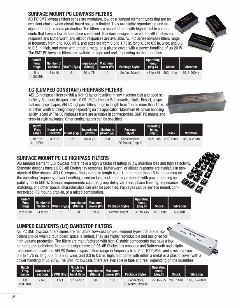
SURFACE MOUNT PC LOWPASS FILTERSAEI PC SMT lowpass filters series are miniature, low-cost lumped element types that are anexcellent choice when circuit board space is limited. They are highly reproducible and de-signed for high-volume production. The filters are manufactured with high-Q stable compo-nents that have a low temperature coefficient. Standard designs have a 0.05-dB Chebyshevresponse and Butterworth and elliptic responses are available. AEI PC Series lowpass filters rangein frequency from 5 to 1000 MHz, and sizes are from 0.5 to 1.75 in. long, 0.3 to 0.5 in. wide, and 0.3to 0.5 in. high, and come with either a metal or a plastic cover, with a power handling of up 20 W.The SMT PC lowpass filters are available in tape and reel, depending on the quantities.
LC (LUMPED CONSTANT) HIGHPASS FILTERSAEI LC highpass filters exhibit a high Q factor resulting in low insertion loss and good se-lectivity. Standard designs have a 0.05-dB Chebyshev, Butterworth, elliptic, Bessel, or spe-cial response shapes. AEI LC highpass filters range in length from 1 in. to more than 15 in.and their width and height vary depending on the application. Maximum RF power handlingability is 500 W. The LC highpass filters are available in connectorized, SMT, PC mount, anddrop-in style packages. Other configurations can be specified.
Cutoff Freq. range
Number ofSections VSWR (Typ.)
Impedance(Ohms)
Maximumpower (W) Package Styles
Operating temp. (deg.C) Shock Vibration
5 to1,000MHz
3 to 16 1.5:1 50 or 75 10 Surface Mount -45 to +85 20G, 11ms 5G, 5-200Hz
Cutoff Freq. range
Number ofSections VSWR (Typ.)
Impedance(Ohms)
Maximumpower (W)
Package styles
Operating temp. (deg.C) Shock Vibration
10 KHz to 10 GHz
3 to 16 1.5:1 50 or 75 500 Connectorized, PC Mount, Drop-in
-55 to +85 20G, 11ms 10G, 5-200Hz
MG007 ANATECH_FINAL_Layout 1 7/28/14 4:42 PM Page 8
SURFACE MOUNT PC LC HIGHPASS FILTERSAEI lumped element (LC) lowpass filters have a high Q factor resulting in low insertion loss and high selectivity.Standard designs have a 0.05-dB Chebyshev response, Butterworth, or elliptic response are available in non-standard filter shapes. AEI LC lowpass filters range in length from 1 in. to more than 15 in. depending onthe operating frequency, power handling, insertion loss, and other requirements with power handing ca-pability up to 500 W. Special requirements such as group delay variation, phase linearity, impedancematching, and other special characteristics can also be specified. Packages can be surface mount, con-nectorized, PC mount, drop-in, or a mixed combination.
Cutoff Freq. range
Number ofSections VSWR (Typ.)
Impedance(Ohms)
Maximumpower (W) Package Styles
Operating temp. (deg.C) Shock Vibration
2 to 2000 4 to 20 1.5:1 50 1 to 20 Surface Mount -45 to +45 10G, 11ms 5-200Hz
LUMPED ELEMENTS (LC) BANDSTOP FILTERSAEI PC SMT lowpass filters series are miniature, low-cost lumped element types that are an ex-cellent choice when circuit board space is limited. They are highly reproducible and designed forhigh-volume production. The filters are manufactured with high-Q stable components that have a lowtemperature coefficient. Standard designs have a 0.05-dB Chebyshev response and Butterworth and ellipticresponses are available. AEI PC Series lowpass filters range in frequency from 5 to 1000 MHz, and sizes are from0.5 to 1.75 in. long, 0.3 to 0.5 in. wide, and 0.3 to 0.5 in. high, and come with either a metal or a plastic cover, with apower handling of up 20 W. The SMT PC lowpass filters are available in tape and reel, depending on the quantities.
Notch Freq. range
Number ofSections VSWR (Typ.)
Notch BWto Pass-band Ratio
Impedance(Ohms)
Maximumpower (W) Package Styles
Operating temp. (deg.C) Shock Vibration
1 to1000MHz
2 to 8 1.5:1 2:1 to 10:1 50 100 Connectors, PC Mount, Drop-in
-55 to +85 20G, 11ms 10 G, 5-200Hz

11
BANDPASS FILTERA bandpass filter passes energy within a certain bandwidthand rejects frequencies below and above this bandwidth.
BANDSTOP/NOTCH FILTERA bandstop or band-rejection filter passes most frequencieswithout disrupting them but significantly attenuates frequen-cies over a specific region. A bandstop filter is essentially theopposite of a bandpass filter. A notch filter is a specific typeof bandstop filter that has a narrow stopband.
HIGHPASS FILTERA bandpass filter passes energy within a certain bandwidthand rejects frequencies below and above this bandwidth.
LOWPASS FILTER A bandpass filter passes energy within a certain bandwidthand rejects frequencies below and above this bandwidth.
DIPLEXERA diplexer is used to combine signals or channels at widelydifferent frequencies. Consequently, diplexers are used tocombine channels in wireless base station transceivers (forexample
DUPLEXERSA duplexer can accommodate frequencies or channels thatare much closer to each other. Duplexers are used to combinesignals in radar or other systems in which the two frequenciesare far apart.
TYPE OF FILTERS
BW
CENTER FREQ.
REJECTION BELOW
PASSBANDREJECTIONABOVE PASSBAND
START OF PASSBAND
BELOW NOTCH
CUTOFF FREQ.
CUTOFF FREQ.LOW BAND
LOW BANDCUTOFF FREQ.HIGH BAND
HIGH BAND
CUTOFF FREQ.
REJECTIONFREQ.
REJECTIONFREQ.
START OF PASSBANDABOVE NOTCH
NOTCH BW
MG007 ANATECH_FINAL_Layout 1 7/28/14 4:42 PM Page 11

14
MORE ABOUT AEIDEFENSE
Our broad range of filters and related products are designed tomeet the tough requirements of EW, ECM, ESM, radar, commu-nications, and other military systems.
SATELLITEWe design filters to cover the uplink and downlink frequenciesfor satcom systems operating up to 20 GHz.
PUBLIC SAFETY Our RF and microwave filters and related products cover all pub-lic safety frequencies from VHF through UHF, as well as thenewly assigned LTE bands. Products can be designed for indoorand outdoor installations.
AVIONIC AND RADARWe specialize in products designed for indoor and outdoor in-stallation within radar, air traffic management, and avionics sys-tems.
WIRELESSAEI specializes in filters, duplexers, multiplexers, multi-bandcombiners/separators for wireless applications, as well as di-rectional couplers, power dividers, and circulators for use in-doors and outdoors in base stations, repeaters, mini-cells,micro-cells operating in all wireless bands, such as GSM, LTE,WCDMA, GPS, WiFi, and more. Filters can be designed for indooror outdoor applications.
POINT TO POINT MICROWAVE COMMUNICATION AEI designs filters, power dividers/combiners duplexers, andcouplers for every microwave point-to-point radio band up to38 GHz.
INDUSTRIAL, SCIENTIFIC, AND MEDICALFrom industrial telemetry and automation system to precisionscientific and measurement set-ups, and MRI or patient moni-toring, AIE’s products deliver high-performance and reliability.
Our Website is the ultimate source of informationabout our products, please visit us frequently.
MG007 ANATECH_FINAL_Layout 1 7/28/14 4:42 PM Page 14

15
IT’S EASY TO ORDERCUSTOM AND STANDARD PRODUCTSStep 1: On Anatech Electronics Home page (www.anatechelec-
tronics.com), click the standard products navigation, orthe specific category you're interested in.
Step 2: Browse and locate the product(s) that matches your re-quirements and click on the part number or anywherein the row of the product.
Step 3: A technical datasheet page will appear, and on the topof the page you can enter the quantity you're interestedin in the "Add to Quote" box, and click.
Step 4: If you are a new user, please register, and if you are al-ready registered please log in. In the Request for Quotepage, click on Submit.
You will receive an Email confirming that you placed a requestfor quote. A quote proposal will be sent to you within 48 hours.You can ask for multiple products quotes just by going to the ap-propriate product, and click on add to quote. All the items in theadd to quote cart will be listed, and you will be able to submit aRequest for Quote for the multiple items listed in you Cart quote.
CUSTOM PRODUCTSStep 1: E-mail, place a Request for Quote on our website the
specific category request quote form, or submit a generalrequest technical info or request a quote standard form.
Step 2: An AEI sales engineer will review your specificationsand provide technical feedback.
Step 3: Once the final specifications are agreed on, AEI will giveyou a unique model number, a quotation for the productin the quantity desired, and a projected delivery date.
Step 4: Once all details have been finalized, submit a purchaseorder to us by e-mail or Call it in.
Step 5: We will ship most products in 4 to 6 weeks ARO viaUPS unless specified otherwise.
FROM-FIT REPLACEMENTAEI can also supply filters that match those offered by othermanufacturers at very competitive prices. Just provide the com-petitor's full part number, a specification control drawing, ormeasured response and mechanical information. The more in-formation you can give to us the more precisely we can matchthe specifications of the filters.
PAYMENTAccepted forms of payment are: Credit Cards: Visa, Master-Card, or American Express. Corporate Check, Wire Transfer,Bank Check.
All orders must be prepaid unless your company has an openaccount with AEI. In order to be approved for an open account,AEI requires the following: 1) A minimum of three business creditreferences. 2) Bank information.
Time required for approval depends on how quickly your busi-ness references and bank respond to our inquiries. Once ap-proved, a letter or e-mail of approval will be sent to you by ourfinance department advising you of payment terms and yourcredit limit (if applicable).
Note: Anatech Electronics (AEI) is a business-to-business or-ganization and will not sell to private individuals. Cor-respondence (e-mail, written, or fax) must indicate acompany affiliation. Referencing a company websitewill be appreciated.
YOUR NOTES
MG007 ANATECH_FINAL_Layout 1 7/28/14 4:42 PM Page 15

CONTACT US TODAY! [email protected] 973.772.4242ANATECH ELECTRONICS, INC. 70 Outwater Lane, Garfield, New Jersey 07026 anatechelectronics.com
MG007 ANATECH_FINAL_Layout 1 7/28/14 4:42 PM Page 16