short term scientific mission (stsm) scientific report · 2019-07-16 · using different types of...
TRANSCRIPT

SHORT TERM SCIENTIFIC MISSION (STSM) – SCIENTIFIC REPORT
The STSM applicant submits this report for approval to the STSM coordinator
Action number: CM 1404 SMARTCATs STSM title: Experimental investigation of kinetic parameters characterizing the combustion of solid biofuels STSM start and end date: 26/03/2018 to 06/04/2018 Grantee name: Tsvetelina Stanimirova Petrova
PURPOSE OF THE STSM
Biomass is considered as good alternative of the fossil fuels. Moreover, the biomass is the largest renewable
energy source. It is characterized with huge availability and low emissions of CO2 [1]. Other advantage of
this energy source is that it can be converted into liquid or gas, to be formed to the pellets/chips or directly
burned [2, 3, 4]. The food and furniture industry, tourism and agriculture produce significant quantities of rest
biomass every year [5].
Biomass based fuels are used in both residential heating and industrial energy systems [6, 7, 8]. Therefore,
it is important to study secondary combustion by-products.
The aim of this STSM was to investigate specific characteristics of biomass based fuel, which is currently
produced and distributed at the Bulgarian fuel market. For that purpose, softwood residues were pelletized
[9] and investigated according to the work plan. In the frame of this mission the emissions of several specific
air pollutants were measured during biomass combustion: soot, char, fly ash, tar and various gaseous
products (O2, CO, CO2, NOx, HC).
This Short Term Scientific Mission is good opportunity to set up a collaboration between our institution in the
field of renewable energy source within the SMARTCATs COST Action CM 1404. The global objective is to
further extend this particular research for detailed investigations and characterization of the
combustion/pyrolysis/gasification of different types of biomass matter.
In particular, the STSM allows to extend my knowledge and to gain experience in an area which is very
promising regarding to its energy potential and impact on the environment.
DESCRIPTION OF WORK CARRIED OUT DURING THE STSMS
The research group of prof. Mario Costa at the Instituto Superior Técnico, Lisboa has significant expertise
in this field of biomass combustion and utilisation. The laboratory has proper equipment based on drop tube
2
furnace (DTF) that allows the performance of the planned experiments. In this installation the combustion
process can be conducted at well controlled conditions, covering wide temperature range.
Prior to this STSM proximate and ultimate analyses of the studied fuel were performed at Technical
University of Sofia. The results are shown on Table 1 and 2.
Table 1. Proximate analysis
Parameter measured Dark pellets (with softwood bark)
Moisture (Wa), % 6.89
Ashes (Aa), % 0.65
Volatile organic compounds (Va), % 78.77
Fixed carbon, % 13.64
Table 2. Ultimate analysis
Fuel Parameter
measured
Unit of measure Mean value Range
Dark pellets
w-% C % 47.77 47.75 – 47.79
w-% H % 6.48 6.40 – 6.56
w-% N % 0.1435 0.136 – 0.151
w-% S % 0.02 NA
w-% O2 % 45.59
Net calorific value
Qid - dry mass
MJ/kg 19.00 18.94 – 19.06
Net calorific value
Qir - as received
MJ/kg 17.38 17.33 – 17.43
Experimental equipment
The current experiment was conducted using the equipment (drop tube furnace - DTF), assembled and
tested in the work group of prof. Mario Costa, Instituto Tecnico Superior, Lisboa, Portugal. This equipment
allows conducting the experiments at well controlled conditions. The DTF operates at maximum temperature
of 13000C. Three thermocouples, type K, are distributed uniformly along the combustion chamber. The
combustion chamber is cylindrical ceramic tube with inner diameter 35 mm and length 1.75 mm. Detailed
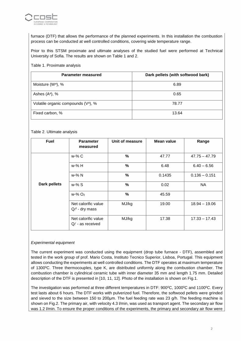
description of the DTF is presented in [10, 11, 12]. Photo of the installation is shown on Fig.1.
The investigation was performed at three different temperatures in DTF: 9000C, 10000C and 11000C. Every
test lasts about 6 hours. The DTF works with pulverized fuel. Therefore, the softwood pellets were grinded
and sieved to the size between 150 to 200μm. The fuel feeding rate was 23 g/h. The feeding machine is
shown on Fig.2. The primary air, with velocity 4.3 l/min, was used as transport agent. The secondary air flow
was 1.2 l/min. To ensure the proper conditions of the experiments, the primary and secondary air flow were
3
continuously controlled during the tests. A pump drives the exhausted gases from the total filter to the gas
analyzer. Its suction flow rate was 10 l/min.
Fig.1 The installation Fig.2 The feeding machine
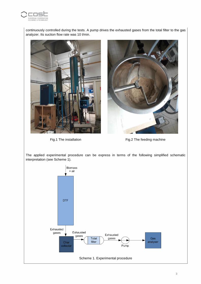
The applied experimental procedure can be express in terms of the following simplified schematic
interpretation (see Scheme 1).
Scheme 1. Experimental procedure

4
The exhausted gases initially pass through the char collector (Fig.3). In this part of the installation the char
is separated from the total flow of the exhaust gases. The next step envisages that the soot, PMs, tar and
other species will be collected in the total filter. The total filter is quartz-microfiber disc with diameter 47 mm.
It is placed in the total filter holder, shown on Fig.4. The gas analyser was connected after the total filter. In
this way, it was possible to measure the following gas phase products: O2, CO, CO2 and NOx.
Fig. 3 The char collector and the total filter Fig. 4 The total filter holder
A morphology and chemical composition of the collected char and soot were done by Scanning electron
microscope (SEM) equipped with energy dispersive X-ray spectroscopy (EDS) detector.
Both samples, collected at the char collector and total filter were additionally examined via burnout.
DESCRIPTION OF THE MAIN RESULTS OBTAINED
Scheme 2 presents general interpretation of the implemented work plan during this STSM.

5
Scheme 2. Experiments performed according to the work plan
After every experiment, the collected amounts of the char and the soot were weighted and stored for further
investigations. The received samples at three different temperatures are given in Table 3.
Table 3. Mass of the collected samples
Temperature in DTF 900OC* 1000OC 1100OC
Mass of the char (g) 0.06375 0.18759 0.18567
Mass of the soot (g) 0.06215 0.13692 0.13154
*Results obtained at 900OC need to be repeated
Fig. 5 Char collector after an experiment Fig. 6 Total filter after an experiment

6
Char and soot were obtained in terms of their mass rate. Thus, the samples in this experiment were collected at
three different temperatures. The results are presented on Fig. 7 and 8. As expected, the results obtained at
1100OC show slightly lower mass rate than those obtained at 1000OC. However, surprisingly the results obtained
at 900OC show opposite trend. Revision of the implemented experimental procedure suggests that this result is
assumed to be due to incorrect test sample preparation. Therefore, the experiment at th is experiment test will be
repeated.
Fig. 7 Char at three different temperatures Fig. 8 Soot at three different temperatures
The main gas phase products obtained simultaneously with the char and the soot are given in Table 4.
Table 4. Gas analyser measurements
Time
duration
(h)
DTF wall
temperature
(OC)
Biomass
feed rate
(g/h)
Average amount of
O2 (%) CO (ppm) CO2 (%) NOx
(ppm)
HC (ppm)
6:15 900 23 19.9952 4.1500 0.1368 0.42 0.42
6:12 1000 23 19.4132 117.3235 0.7656 6.62 0
6:13 1100 23 19.1583 227.2 0.9643 3.09 0
Morphology analyses was carried out of the collected samples of char. Fig. 9 and 10 show SEM images from char
samples taken at different temperatures (1000OC and 1100OC). Obviously the collected material consists not only
of char but also tar was observed. It is assumed that the tar is formed due to eventual condensation that is occurring
during the sampling process. It is expected that this process is caused by the lower temperature in the char
collector.

7
Fig.9 Char at 10000C Fig.10 Char at 11000C
Morphology analyses was done also for the soot collected from the total filter during the experiments. The results
obtained with SEM are shown on Fig. 11 and Fig. 12 for the soot samples collected at two different temperatures.
The images show two general type of structures - particulate matter and tar.
Fig.11 Soot at 10000C Fig.12 Soot at 11000C
Chemical composition analysis was carried out for the samples of char and soot described above. Fig. 13 is an
example of the results for the chemical composition of the char collected at 11000C. The results were obtained by
the SEM and are herein presented in weight %: C - 80.91, O2 – 13.27, Mg– 0.59, Si – 0.25, S – 0.66, K– 1.18, Ca
– 3.14.

8
Fig.13 SEM results for a char collected at 11000C
Furthermore, detailed analysis of the chemical composition was done by energy dispersive X-ray spectroscopy
detector for the samples of char and soot. Fig. 14 and 15 demonstrate the relative distribution of the main elements
in the samples of char and soot, obtained during the biomass combustion at 1100OC. The results show that the
predominant elements are carbon, oxygen and calcium.
Fig.14 Chemical composition of the char at 1100OC Fig.15 Chemical composition of the soot at 1100OC
In addition, the collected test samples from the total filter were subsequently analyzed for the ash content following
the procedures used for the proximate analysis of solid fuels.
The results are summarised in Table 5. As expected, higher combustion temperature leaded to smaller amount of
ash and larger amount of soot, respectively (see the results for the soot test samples). However, the results for
the char did not follow the same trend.
80,91
13,27
1,183,14 0,59 0,25 0,66
Weight % at 1100OC
C O K Ca Al Mn
Fe Mg Si P S
14,76
34,91
4,81
0,831,34
0,71
40,09
1,51 1,05
Weight % at 1100OC
C O2 Mg Al Si
P K Ca Mn Fe
CaSiMgO S K
Ca
C
0 1 2 3 4 5 6 7 8 9 10
keVFull Scale 1086 cts Cursor: -0.088 (29 cts)
Spectrum 5

9
Table 5. Total ash content after burnout
Char Soot
Temperature (oC) 900 1000 1100 900 1000 1100
Initial (g) 14.45634 15.39537 14.73784 14.42493 14.26727 15.51291
Final (g) 14.45068 15.37793 14.72977 14.42296 14.2563 14.49111
Ash (%) 99.96085 99.88672 99.94524 99.98634 99.92311 93.41323
FUTURE COLLABORATIONS
The STSM was focused on the combustion of alternative bio-fuels that are usually characterized with low
level of the air pollutants. But there is plenty of biomass that have been seen as such recently. However,
their chemical-kinetic parameters are not fully understood in terms of the mechanisms of soot, tar and char
formation.
During this STSM the work plan was successfully implemented despite the limited time constrains. There is
ongoing work on the ash analysis. The results will be available within few weeks.
The outcome of this collaboration can be summarised as follows:
This work aimed at laying down the foundations of long term collaboration between the two institutions –
Technical University of Sofia (Bulgaria) and Instituto Tecnico Superior, Lisboa (Portugal) in the field of
renewable energy source investigation. Based on the received results, further investigation was planned
using different types of biomass matter, mainly agriculture residue (e.g. coffee husk, sunflower pellets and
cherry stones). These residues from the food industry are received in big amount every year and they have
big energy potential. Both research teams, consider the good option for further investigations in the field of
biomass combustion and air pollutants. This future study will be in line with the goals of WG2 - Chemistry
for control of by-products in Smart Energy Carrier conversion. It would be very useful also to measure the
PMs for each fuel.
Currently, there is an ongoing discussion about future possibility of:
modeling of the biomass combustion process which was studied in the frame of this STSM;
new investigations on combustion and/or gasification of the above mentioned biomass.
References
[1] D. Koruba, J. Piotrowski, J. Latosinska, Biomass – alternative renewable energy source to the fossil fuels,
E3S Web of Conference 14, 02015 (2017), Energy and Fuels 2016, DOI: 10.1051/e3sconf/20171402015
[2] http://eco-globe.com/biomass-energy-alternative-fossil-fuels/
[3] V. Kirubakaran, V. Sivaramakrishnan, R. Nalini, T. Sekar, M. Premalatha, P. Subramanian, A review on
gasification of biomass, Renewable and Sustainable Energy Reviews 13 (2009) 179–186
[4] http://www.volund.dk/Biomass_energy/Technologies/Gasification_of_biomass
[5] E. Vandamme, T. Anthonis, S. Dobbelaere, Industrial Biomass: Source of Chemicals, Materials, and
Energy!, Royal Belgian Academy of Science, ISBN 9789065690777, February 2011
[6] https://www.renewableenergyhub.co.uk/biomass-boiler-information/commercial-and-industrial-
biomass.html
[7] https://www.sigmathermal.com/wood-biomass-energy/

10
[8] N.S. Rathore, N. L. Panwar, Industrial Application of Biomass Based Gasification System, World Applied
Sciences Journal 5 (4): 406-409, 2008, ISSN 1818-4952
[9] Axel Trade 2009 LTD, Samokov, Bulgaria
[10] G. Wang, R.B. Silva, J.L.T. Azevedo, S. Martins-Dias, M. Costa, Evaluation of the combustion behaviour
and ash characteristics of biomass waste derived fuels, pine and coal in a drop tube furnace, Fuel 117 (2014)
809–824.
[11] T. Botelho, M. Costa, M. Wilk, A. Magdziarz, Evaluation of the combustion characteristics of raw and
torrefied grape pomace in a thermogravimetric analyzer and in a drop tube furnace, Fuel 212 (2018) 95–100
[12] Vera Branco, M. Costa, Effect of particle size on the burnout and emissions of particulate matter from
the combustion of pulverized agricultural residues in a drop tube furnace, Energy Conversion and
Management 149 (2017) 774–780