should google go nuclear - askmar.com google go nuclear.pdf · should google go nuclear? inertial...
TRANSCRIPT
Should Google Go Nuclear?
Inertial electrostatic confinement fusion provides a potential breakthrough in designing and implementing practical fusion power plants.by Mark Duncan, askmar, www.askmar.com
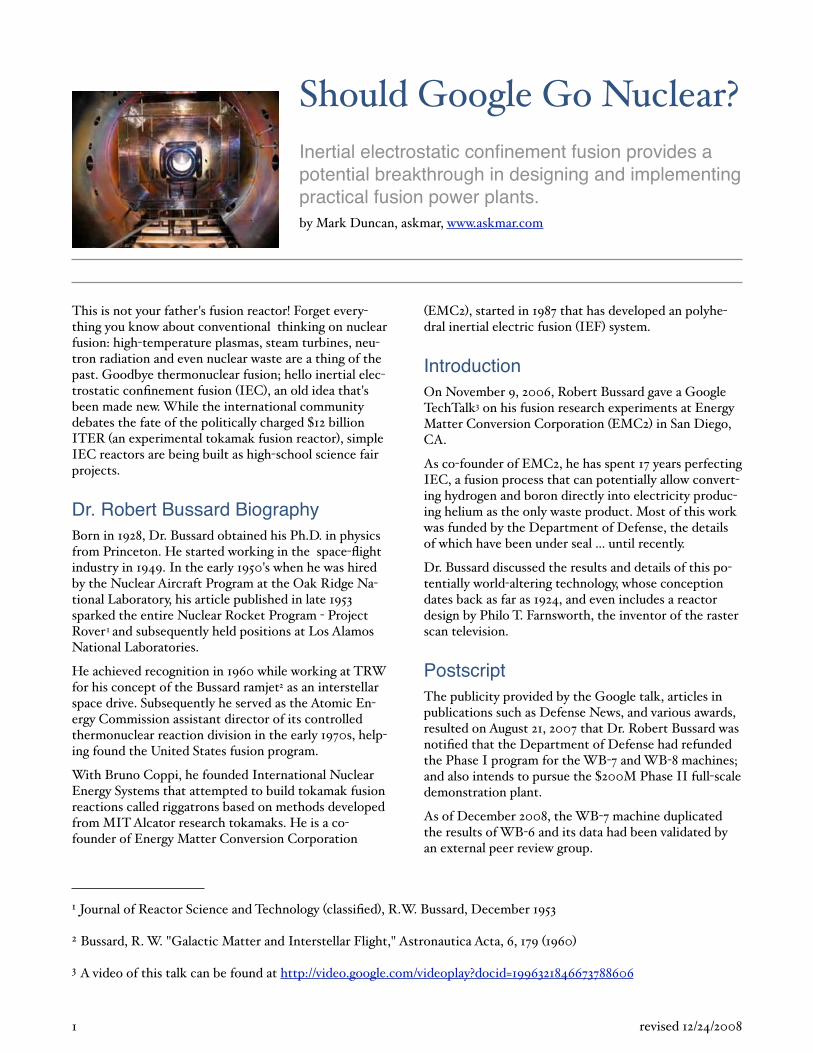
This is not your father's fusion reactor! Forget everything you know about conventional thinking on nuclear fusion: high temperature plasmas, steam turbines, neutron radiation and even nuclear waste are a thing of the past. Goodbye thermonuclear fusion; hello inertial electrostatic confinement fusion IEC , an old idea that's been made new. While the international community debates the fate of the politically charged 12 billion ITER an experimental tokamak fusion reactor , simple IEC reactors are being built as high school science fair projects.
Dr. Robert Bussard BiographyBorn in 1928, Dr. Bussard obtained his Ph.D. in physics from Princeton. He started working in the space flight industry in 1949. In the early 1950's when he was hired by the Nuclear Aircraft Program at the Oak Ridge National Laboratory, his article published in late 1953 sparked the entire Nuclear Rocket Program Project Rover1 and subsequently held positions at Los Alamos National Laboratories.
He achieved recognition in 1960 while working at TRW for his concept of the Bussard ramjet2 as an interstellar space drive. Subsequently he served as the Atomic Energy Commission assistant director of its controlled thermonuclear reaction division in the early 1970s, helping found the United States fusion program.
With Bruno Coppi, he founded International Nuclear Energy Systems that attempted to build tokamak fusion reactions called riggatrons based on methods developed from MIT Alcator research tokamaks. He is a cofounder of Energy Matter Conversion Corporation
EMC2 , started in 1987 that has developed an polyhedral inertial electric fusion IEF system.
IntroductionOn November 9, 2006, Robert Bussard gave a Google TechTalk3 on his fusion research experiments at Energy Matter Conversion Corporation EMC2 in San Diego, CA.
As co founder of EMC2, he has spent 17 years perfecting IEC, a fusion process that can potentially allow converting hydrogen and boron directly into electricity producing helium as the only waste product. Most of this work was funded by the Department of Defense, the details of which have been under seal ... until recently.
Dr. Bussard discussed the results and details of this potentially world altering technology, whose conception dates back as far as 1924, and even includes a reactor design by Philo T. Farnsworth, the inventor of the raster scan television.
PostscriptThe publicity provided by the Google talk, articles in publications such as Defense News, and various awards, resulted on August 21, 2007 that Dr. Robert Bussard was notified that the Department of Defense had refunded the Phase I program for the WB 7 and WB 8 machines; and also intends to pursue the 200M Phase II full scale demonstration plant.
As of December 2008, the WB 7 machine duplicated the results of WB 6 and its data had been validated by an external peer review group.
1 revised 12/24/2008
1 Journal of Reactor Science and Technology classified , R.W. Bussard, December 1953
2 Bussard, R. W. "Galactic Matter and Interstellar Flight," Astronautica Acta, 6, 179 1960
3 A video of this talk can be found at http://video.google.com/videoplay?docid=1996321846673788606
Inertial Electric Fusion IEF : An Old Idea TriumphantThe talk is structured into five sections:
• Fundamental issues regarding approaches to fusion, and relevant problems
• The research that EMC2 did from 1994 to 2005
• What we learned from our research
• Applications for fusion power
• Time and money required to do it
Nuclear Fusion: What It Is and How to Get ItFire, Fission, and FusionAn example of a chemical reaction is when you burn hydrogen and water to produce water and energy.
PH1
PH1
+ [10 eV]P
H1
P
H1
Fire
NP
P
P
NN N
N
PO16
N
P
P
PN
N
N
N
P
NP
P
P
NN N
N
PO16
N
P
P
PN
N
N
N
P
Figure 1 — Fire
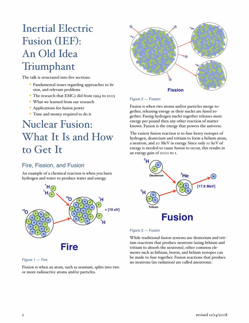
Fission is when an atom, such as uranium, splits into two or more radioactive atoms and/or particles.
P
PP
P
P
NN
NN
N
U235 P
PP
P
P
NN
NN
N
P
PP
P
P
NN
NN
N
P
PP
P
P
NN
NN
N
P
P
P
P
P
N
N
N
N
N
P
PP
P
P
NN
N
N
N
P
PP
P
P
NN
NN
N
P
PP
P
P
NN
NN
N
P
PP
P
P
NN
NN
NP
PP
P
P
NN
N
N
N
P
PP
P
P
NN
NN
N
P
PP
P
P
NN
NN
N
P
PP
P
P
NN
NN
N
P
PP
P
P
NN
NN
N
P
P
P
P
P
N
N
N
N
N
P
PP
P
P
NN
NN
N
P
PP
P
P
NN
NN
N
P
PP
P
P
NN
NN
N
PPNN
N
NNN
N
N
N
N
N
N
N
N
N
NN
N N
N
N
N
N
N
N
NN
N
N
N
N
N
NN
N
N
N
NN
N
NN
NN
N
N
N N
N
N
N
N
N
Fission
P
P
P
P
P
N
N
N
NN
Kr92
P
PP
P
P N
N
N
N
N
P
PP
P
P
N
N
N
N
N
P
PP
P
P
NN
NN
N
P
P
P
P
P
N
N
N
N
N
P
P
PP
P
N
N
N
N
N
P
PP
P
P
NN
NN
N
P
PP
P
P
NN
NN
N
P
PP
P
P
NN
N
N
N
P
P
P
P
P
N
N
N
N
N
P
PP
P
P
NN
N
N
N
P
PP
P
P
NN
N
N
N
P
PP
P
P
NN
NN
N
P
PP
P
P
NN
NN
N
P
PP
P
P
N
N
N
N
N
P
P
P
P
P
N
N
N
N
N
P
P
PP
P
N
N
N
NN
P
PP
P
P
N
N
N
N
N
P
P
N
N
N
NNN
N
N
N
N
N N
N
N
N
N
N
N N
N
N
N
N
N
N
NN
N
N
N
N
N
N
NN
N
N
NN
N
NN
N
N
N
N
N
N
N
NN
N
N
Ba141N
Figure 2 — Fission
Fusion is when two atoms and/or particles merge together, releasing energy as their nuclei are fused together. Fusing hydrogen nuclei together releases more energy per pound then any other reaction of matter known. Fusion is the energy that powers the universe.
The easiest fusion reaction is to fuse heavy isotopes of hydrogen, deuterium and tritium to form a helium atom, a neutron, and 20 MeV in energy. Since only 10 keV of energy is needed to cause fusion to occur, this results in an energy gain of 2000 to 1.
P
P
N
N
He4
[17.6 MeV]
PN
H2
P N
NH3
Deuterium
Tritium
N
FusionFigure 3 — Fusion
While traditional fusion systems use deuterium and tritium reactions that produce neutrons using lithium and tritium to absorb the neutrons , other common elements such as lithium, boron, and helium isotopes can be made to fuse together. Fusion reactions that produce no neutrons no radiation are called aneutronic.
2 revised 12/24/2008
NP
PP
P
P
NN
NN
N
NP
PP
P
P
NN
NN
N
P
P
P
P
N
N
B11
C12
He4
P
P
P
NN N
N
PBe12
P
P
N
N
He4
P
P
N
N
He4
e
[3.76 MeV] [2.46 MeV]
[2.46 MeV]
Figure 4 — Aneutronic Fusion Example
In the above example, a proton fuses with Boron 11 and becomes unstable Carbon 12 that quickly decays, producing three Helium 4 atoms and three photons. The problem with aneutronic fusion is that much higher energies are required to get the same cross section then are needed for deuterium and tritium fusion. Aneutronic fusion is the exception, most fusion events cause some radiation hazards. The following table provides examples of other common types of fusion:
Fusion Type
Fusion Reaction
Reaction Energy
Totally neutron free
p + 11B > 3 4He6Li + 6Li > 3 4He p, 3He cycle
8.70 MeV10.44 MeV
Small neutron output 5 to 9
2H + 2H 3H + p2H + 2H > 3He + n 2.45 MeV3He > 2H + 4He + p
10.24 MeV
High neutron radiation >80
2H + 3H > 4He + n 14.1 MeV
Fusion can be used to generate heat, steam and electric power, as well as produce isotopes and cause nuclear transmutation.
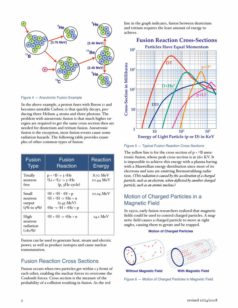
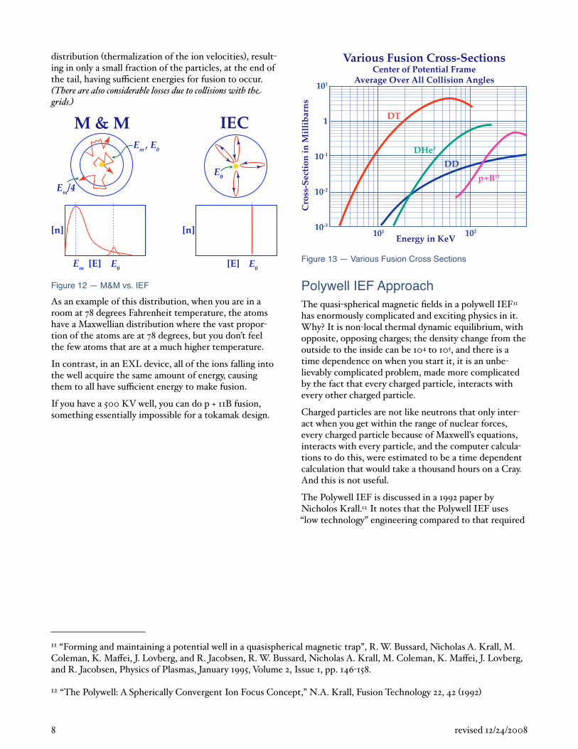
Fusion Reaction Cross SectionsFusion occurs when two particles get within 1.3 fermi of each other, enabling the nuclear forces to overcome the Coulomb forces. Cross section is the measure of the probability of a collision resulting in fusion. As the red
line in the graph indicates, fusion between deuterium and tritium requires the least amount of energy to achieve.
DD
DT
p+Li6
D+He3
Fusion Reaction Cross-Sections
Cro
ss-S
ecti
on in
Mil
lib
arn
s
104
103
102
10
1 10 103102
Energy of Light Particle (p or D) in KeV
Particles Have Equal Momentum
p+B11
Figure 5 — Typical Fusion Reaction Cross Sections
The yellow line is for the cross section of p + 11B aneutronic fusion, whose peak cross section is at 560 KV. It is impossible to achieve this energy with a plasma having with a Maxwellian energy distribution since most of its electrons and ions are emitting Bremsstrahlung radiation. This radiation is caused by the acceleration of a charged particle, such as an electron, when deflected by another charged particle, such as an atomic nucleus.
Motion of Charged Particles in a Magnetic FieldIn 1950s, early fusion researchers realized that magnetic fields could be used to control charged particles. A magnetic field causes a charged particle to move at right angles, causing them to gyrate and be trapped.
Without Magnetic Field With Magnetic Field
Motion of Charged Particles
Figure 6 — Motion of Charged Particles in Magnetic Field
3 revised 12/24/2008
This resulted in various di erent magnetic confinement systems being tried:
• Magnetic mirror
• Closed system torus
• Basic tokamak
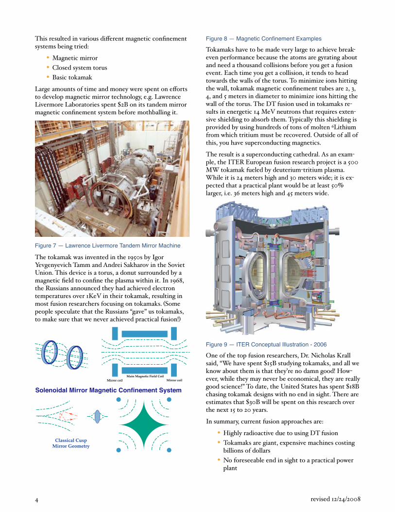
Large amounts of time and money were spent on e orts to develop magnetic mirror technology, e.g. Lawrence Livermore Laboratories spent 2B on its tandem mirror magnetic confinement system before mothballing it.
Figure 7 — Lawrence Livermore Tandem Mirror Machine
The tokamak was invented in the 1950s by Igor Yevgenyevich Tamm and Andrei Sakharov in the Soviet Union. This device is a torus, a donut surrounded by a magnetic field to confine the plasma within it. In 1968, the Russians announced they had achieved electron temperatures over 1KeV in their tokamak, resulting in most fusion researchers focusing on tokamaks. Some people speculate that the Russians “gave” us tokamaks, to make sure that we never achieved practical fusion!
Mirror coil Mirror coil Main Magnetic Field Coil
Classical Cusp Mirror Geometry
Solenoidal Mirror Magnetic Confinement System
Figure 8 — Magnetic Confinement Examples
Tokamaks have to be made very large to achieve breakeven performance because the atoms are gyrating about and need a thousand collisions before you get a fusion event. Each time you get a collision, it tends to head towards the walls of the torus. To minimize ions hitting the wall, tokamak magnetic confinement tubes are 2, 3, 4, and 5 meters in diameter to minimize ions hitting the wall of the torus. The DT fusion used in tokamaks results in energetic 14 MeV neutrons that requires extensive shielding to absorb them. Typically this shielding is provided by using hundreds of tons of molten 6Lithium from which tritium must be recovered. Outside of all of this, you have superconducting magnetics.
The result is a superconducting cathedral. As an example, the ITER European fusion research project is a 500 MW tokamak fueled by deuterium tritium plasma. While it is 24 meters high and 30 meters wide; it is expected that a practical plant would be at least 50 larger, i.e. 36 meters high and 45 meters wide.
Figure 9 — ITER Conceptual Illustration - 2006
One of the top fusion researchers, Dr. Nicholas Krall said, “We have spent 15B studying tokamaks, and all we know about them is that they’re no damn good! However, while they may never be economical, they are really good science!” To date, the United States has spent 18B chasing tokamak designs with no end in sight. There are estimates that 30B will be spent on this research over the next 15 to 20 years.
In summary, current fusion approaches are:
• Highly radioactive due to using DT fusion
• Tokamaks are giant, expensive machines costing billions of dollars
• No foreseeable end in sight to a practical power plant
4 revised 12/24/2008
• No predictability all empirical
We believe that the tokamak approach to fusion doesn’t have a practical solution.4
Fusion Can Be DoneWe know that fusion works, just walk outside and look up at the stars at night. They are held together by a direct force field that works well and e ciently; gravity pulling them together from all directions.
Only one other force is like gravity: the electric field or “coulomb” force between electrically charged particles. Charged particles of opposite sign attract each other with direct forces; charged particles in electric fields feel forces along field gradients. This is the basis for electric fusion, using electric forces and electric fields to eciently hold fusion fuel plasmas together.
Inertial Electrostatic Confinement (IEC) Fusion HistorySo how do you use an electric field to make it accelerate the particles you want to collide towards each other? The solution is to use a spherical electric field. Since a spherical field has 1/r2 convergence, the density increases by 1/r4, causing all of the fusion to be focused in a very small area at the center of the sphere called the core. Furthermore, fusion power is a function of:
Fusion power = particle density 2 x cross section x particle velocity x volume
But we were not the first to understand this. Work on inertial electrostatic confinement IEC fusion systems first started in 1924 with a paper5 by Irving Langmuir and Katharine B. Blodgett who were working on the East Coast.
Their work was followed in 1959 by a paper by William Watson6 at Los Alamos National Laboratories. In his
fusion machine, you charged one grid to a positive potential, creating a negative potential well, between it and a negative charged grid. When you dropped ions into it at the edge, they would go back and forth, recirculating like marbles in a well. If the ions didn’t collide, they rode back up the well instead of getting lost like in a tokamak.
The problem with Watson’s approach was the grid. You needed 100,000 transits of electrons before you would get a fusion from the ion population. But the best grids that they could make were only 90 to 95 transparent with the result that you typically had a collision with the grid before a fusion event could occur. The high grid interception rate resulted both in losing energy and melting the grids. It simply wasn’t workable.
Filo Farnsworth7, who pioneered raster scan television, had a post doctoral student, Bob Hirsch who wrote a classic IEC paper8 in 1967. The Hirsch Farnsworth machine eliminated the electron interception problem by inverting the grid, biasing it negatively, causing it to accelerate the ions directly, so you would only need several thousand transits before fusion would occur.
Unfortunately they now had the problem of ion interception, so they were only able to get a recirculating factor of 7 or 10 before a grid collision occurred. Still, their machine set and still holds a world record for this particular type of machine with 2 1010 neutrons/second for DT fusion in the late 1960s. In fact, Bob Hirsch still has it sitting on his desk in Alexandra, Virginia.
Bob was a brilliant designer who used ion guns that were spherically focused at each other. However his machine only achieved 10 6 gain power output / power input due to grid loss problem and secondary losses due to wall collisions.
5 revised 12/24/2008
4 “Inherent Characteristics of Fusion Power Systems: Physics, Engineering, and Economics,” Robert W. Bussard and Nicholas Krall, December 1994, Fusion Technology, Volume 26, pp. 1326 1336.
5 "Currents Limited by Space Charge Between Concentric Spheres," Irving Langmuir and Katharine B. Blodgett, Physics Review, 23, pp. 49 59, 1924.
6 “On the inertial electrostatic confinement of a plasma,” William C. Elmore, James L. Tuck, and Kenneth M. Watson, Los Alamos Scientific Laboratory, Los Alamos, New Mexico, Physics of Fluids 2, 239 1959
7 “Electric Discharge Device for Producing Interactions Between Nucleii,” P.T. Farnsworth, U.S. Patent No. 3,358,402, issued June 28, 1966, initially filed May 5, 1956, reviewed Oct. 18, 1960, filed Jan. 11, 1962.
8 “Inertial Electrostatic Confinement of Ionized Fusion Gases,” R.L. Hirsch, Journal of Applied Physics 38, 4522 1967R.L. Hirsch, “Experimental studies of a deep, negative, electrostatic potential well in spherical geometry,” Physics of Fluids 11, 2486 1968 .
IonAccelerating
Well
Ion/Grid Collision Losses Cusp Electron Losses
Injectionat High Ei
Injectionat High E0
IonGun
ElectronGun
MagnetCoils
Grids
Cusp BFields
Q
E0
0
E0
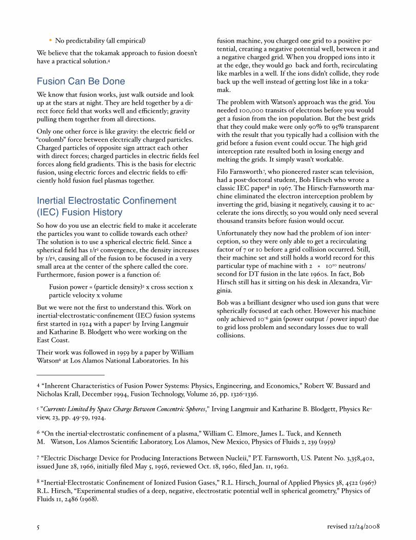
IXL - Ion Acceleration EXL - Electron Acceleration
IonGun
Injectionat Low Ei
Figure 10 — IXL vs. EXL Machine Geometry
IEC machines can be built in two ways. One we call IXL for ion acceleration, which is what Robert Hirsch and Filo Farnsworth did by building two spherical grids, one inside the other. Once ionized, the ionized plasma was drawn to the inner negatively charged electrode. As we mentioned before, the grids killed them.
The EXL or electron acceleration method9 takes the William Watson concept and replaces the grids with magnetic fields. While magnetic fields do not contain neutral plasma worth a darn, which is the tokamak problem; they contain electrons very well, since they don’t weigh anything. A deuterium atom is 3,600 times heavier then an electron. It is easy to contain electrons, or you wouldn’t find Varian Associates being able to build high power klystron tubes.
This eliminates the problem of losses due to the grids, and replaces it with the problem of the rate at which electrons transport themselves across the magnetic fields and hit the walls of the magnets.
EXL is a system that provides recirculation. Low energy electrons and ions are heated by incoming high energy electrons in microsecond time scales and become part
of the circulating system. Fusion products escape to the system walls.
You prime the EXL device by using a quasi spherical magnetic fields to trap energetic electrons to build up a William Watson spherical negative potential well. With just electrons and no ions, you get a well that is very sharp at the edges and flat in the middle.
Then you drop ions over the edge of the well that see the well and begin to accumulate in the middle, becoming focused at the 1/r2 core that oscillate back and forth across the core, acting like a spherical colliding beam machine. The fuel gas input at the potential well edge is neutral ions that are ionized by the incoming electrons. As more ions are added, they form a quasi central anode, pushing it up in the center as shown, you want to be slightly ion rich. You can keep doing this up to the point that you finally blow the well out. The range from flatness to blowout is about 5 or 8, so there is a lot of room to play around with in ion flow control.
The device is almost electrically neutral. The departure from neutrality to create a 100 KV well is only one part in a million, when you have a density of 1012 cm3. The
6 revised 12/24/2008
9 “Some Physics Considerations of Magnetic Inertial Electrostatic Confinement: a New Concept for Spherical Converging Flow Fusion,” R.W. Bussard, Fusion Technology 19, 273 1991 .
departure from neutrality is so small that we found current computer codes and computers available to us were incapable of analyzing it because of the numeric noise in the calculations by a factor of a thousand.
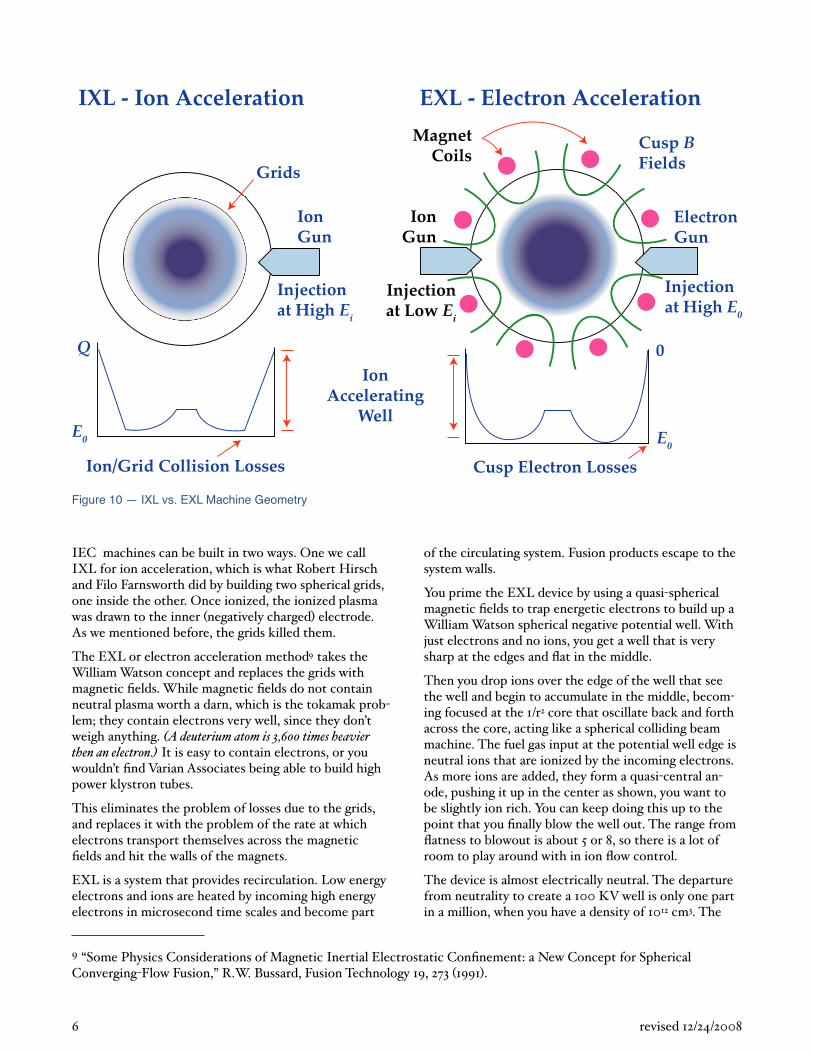
The fundamental problem in constructing this device is making a good quasi spherical magnetic field. We can’t tolerate the mirror losses at the equator that Livermore spent time and money on. We needed a magnetic field having only point cusps. If you put a north pole and north pole together, you get an enormous loss at the equator.
There is only one configuration that works, and that is the one that we patented. It is a configuration that is a polyhedron where the coils are all on the edges of the polyhedron, and the polyhedron has the property that there are an even number of faces around every vertex so that alternate faces are north, south, north, south, north, south.
If you look at the cube which constitutes the normal biconic cusp, it only has three faces around every vertex, so you have the line cusp problem. The only thing we could find to solve it is to make a system that is quasispherical with no magnetic monopole, so you have to do it from the surface, so you only have have point cusp losses.
With the EXL device we have decoupled two problems. The first problem is the electron losses necessary to drive the well; how many electrons you can lose and still make fusion. The main losses occur through magnetic cusps to the wa s . The power balance is set by the injected electron losses. The second problem is the number of ions necessary to be dropped into the well to make fusion.
Point cusps are what we earlier showed in the mirror machine illustrations. The reflection coe cient in a low density mirror machine varies as 1/B field. But this wasn’t adequate for our needs. The kinetic pressure of the electrons needs to be balanced by the magnetic field pressure, it is very much like blowing up a balloon. As you push the magnetic field out, the scaling ceases to be mirror scaling and becomes cusp confinement scaling that scales at 1/B2.
� �Plasmapressure
Magnetic field pressure
�� � Eq. 1
We’re making the loss holes that the electrons can go out, smaller and smaller, the harder we drive it with electron injection, up until the point where we inject too many electrons and it begins to open up the cusp holes and those equations are all understood now . We call
this the wi eball e ect10 that enables cusp scaling.
�������������� ������������������ ���
�����������
�������� ���
�������� ���
�������� ���
���������� ��
�������������
�������������
���������� ��
������������������������������������ ���
Figure 11 — Wiffleball
The other problem with electron confinement is magnetic insulation Magrid . The walls for the structure, the containers for the coils, all the metal parts, have to be kept from being seen directly by the electrons by means of magnetic insulation. It has turned out to be that the devil is in the details; we finally resolved them at the end of 2005. You have to have e ective Magrid insulation to have a practical machine.
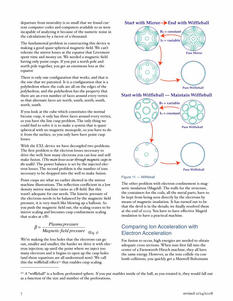
Comparing Ion Acceleration with Electron AccelerationFor fusion to occur, high energies are needed to obtain adequate cross sections. When ions first fall into the center of a Farnsworth Hirsch machine, they all have the same energy. However, as the ions collide via coulomb collisions, you quickly get a Maxwell Boltzmann
7 revised 12/24/2008
10 A “wi eball” is a hollow, perforated sphere. If you put marbles inside of the ball, as you rotated it, they would fall out as a function of the size and number of the perforations.
distribution thermalization of the ion velocities , resulting in only a small fraction of the particles, at the end of the tail, having su cient energies for fusion to occur. There are also considerable losses due to co isions with th
grids.
M & M IEC
E0Em [E] E0
[E]
[n][n]
E0
Em , E0
Em/4
Figure 12 — M&M vs. IEF
As an example of this distribution, when you are in a room at 78 degrees Fahrenheit temperature, the atoms have a Maxwellian distribution where the vast proportion of the atoms are at 78 degrees, but you don’t feel the few atoms that are at a much higher temperature.
In contrast, in an EXL device, all of the ions falling into the well acquire the same amount of energy, causing them to all have su cient energy to make fusion.
If you have a 500 KV well, you can do p + 11B fusion, something essentially impossible for a tokamak design.
DD
DT
p+B11
DHe3
Various Fusion Cross-Sections
Cro
ss-S
ecti
on in
Mil
lib
arn
s
101 102
Energy in KeV
Center of Potential FrameAverage Over All Collision Angles
101
1
10-1
10-2
10-3
Figure 13 — Various Fusion Cross Sections
Polywell IEF ApproachThe quasi spherical magnetic fields in a polywell IEF11 has enormously complicated and exciting physics in it. Why? It is non local thermal dynamic equilibrium, with opposite, opposing charges; the density change from the outside to the inside can be 104 to 105, and there is a time dependence on when you start it, it is an unbelievably complicated problem, made more complicated by the fact that every charged particle, interacts with every other charged particle.
Charged particles are not like neutrons that only interact when you get within the range of nuclear forces, every charged particle because of Maxwell’s equations, interacts with every particle, and the computer calculations to do this, were estimated to be a time dependent calculation that would take a thousand hours on a Cray. And this is not useful.
The Polywell IEF is discussed in a 1992 paper by Nicholos Krall.12 It notes that the Polywell IEF uses “low technology” engineering compared to that required
8 revised 12/24/2008
11 “Forming and maintaining a potential well in a quasispherical magnetic trap”, R. W. Bussard, Nicholas A. Krall, M. Coleman, K. Ma ei, J. Lovberg, and R. Jacobsen, R. W. Bussard, Nicholas A. Krall, M. Coleman, K. Ma ei, J. Lovberg, and R. Jacobsen, Physics of Plasmas, January 1995, Volume 2, Issue 1, pp. 146 158.
12 “The Polywell: A Spherically Convergent Ion Focus Concept,” N.A. Krall, Fusion Technology 22, 42 1992
to build a tokamak. While, the physics of an IEC is very involved and complex, such devices are small, cheap, and quick to build compared to tokamak. They are classical physics machines. Unfortunately, there are few people who are trained in gaseous electronics, nobody is trained on gyrotrons13 and thyratrons,14 thus you can’t find people similar to those who did this type of work in the 1920s and 1930s.
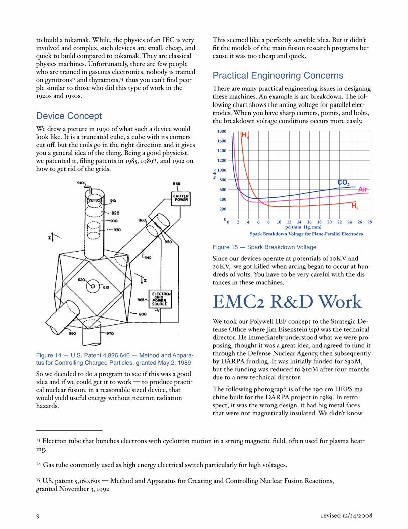
Device ConceptWe drew a picture in 1990 of what such a device would look like. It is a truncated cube, a cube with its corners cut o , but the coils go in the right direction and it gives you a general idea of the thing. Being a good physicist, we patented it, filing patents in 1985, 198915, and 1992 on how to get rid of the grids.
Figure 14 — U.S. Patent 4,826,646 — Method and Appara-tus for Controlling Charged Particles, granted May 2, 1989
So we decided to do a program to see if this was a good idea and if we could get it to work to produce practical nuclear fusion, in a reasonable sized device, that would yield useful energy without neutron radiation hazards.
This seemed like a perfectly sensible idea. But it didn’t fit the models of the main fusion research programs because it was too cheap and quick.
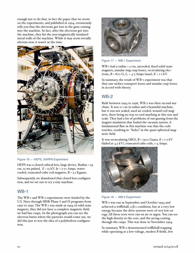
Practical Engineering ConcernsThere are many practical engineering issues in designing these machines. An example is arc breakdown. The following chart shows the arcing voltage for parallel electrodes. When you have sharp corners, points, and bolts, the breakdown voltage conditions occurs more easily.
Spark Breakdown Voltage for Plane-Parallel Electrodes
pd (mm. Hg. mm)
Vol
ts
1800
1600
1400
1200
1000
800
600
400
200
00 2 4 6 8 10 12 14 16 18 20 22 24 26 28
H 2
Air CO 2
H 2
Figure 15 — Spark Breakdown Voltage
Since our devices operate at potentials of 10KV and 20KV, we got killed when arcing began to occur at hundreds of volts. You have to be very careful with the distances in these machines.
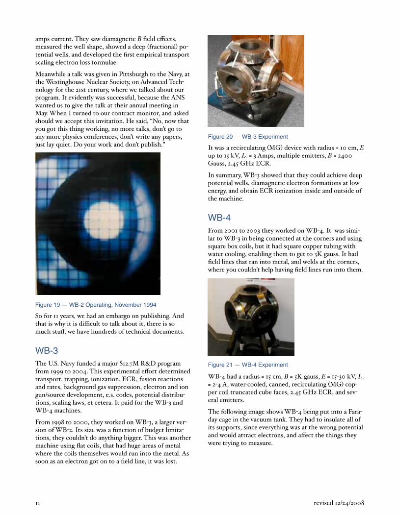
EMC2 R&D WorkWe took our Polywell IEF concept to the Strategic Defense O ce where Jim Eisenstein sp was the technical director. He immediately understood what we were proposing, thought it was a great idea, and agreed to fund it through the Defense Nuclear Agency, then subsequently by DARPA funding. It was initially funded for 30M, but the funding was reduced to 10M after four months due to a new technical director.
The following photograph is of the 190 cm HEPS machine built for the DARPA project in 1989. In retrospect, it was the wrong design, it had big metal faces that were not magnetically insulated. We didn’t know
9 revised 12/24/2008
13 Electron tube that bunches electrons with cyclotron motion in a strong magnetic field, often used for plasma heating.
14 Gas tube commonly used as high energy electrical switch particularly for high voltages.
15 U.S. patent 5,160,695 Method and Apparatus for Creating and Controlling Nuclear Fusion Reactions, granted November 3, 1992
enough not to do that, in fact the paper that we wrote on the experiments, and published in 1994, erroneously tells you that the electrons got lost in the guns coming into the machine. In fact, after the electrons got into the machine, they hit the non magnetically insulated metal walls of the machine. While it may seem trivially obvious now, it wasn’t at the time.
Figure 16 — HEPS, DARPA Experiment
HEPS was a closed cubical box, large device, Radius = 93 cm, 25 ms pulsed, E = 15 kV, Ie = 5 10 Amps, watercooled, truncated cube coil magnets, B = 3.5 Kgauss.
Subsequently, we abandoned that closed box configuration, and we set out to try a tiny machine.
WB-1The WB 1 and WB 2 experiments were funded by the U.S. Navy through SBIR Phase I and II programs from 1992 to 1995. The WB 1 was made in 1994 of solid state magnets, they did not have a complete magnetic field, we had line cusps. In the photograph you can see the electron burns where the particles would come out, we did this just to test the idea of a polyhedron configuration.
Figure 17 — WB-1 Experiment
WB 1 had a radius = 5 cm, uncooled, fixed solid state magnets, annular ring cusp losses, recirculating electrons, B = 800 G, I = 4 5 Amps max , E = 1 2 kV.
In summary, the result of WB 1 experiment was that they saw surface transport losses and annular cusp losses in accord with theory.
WB-2Built between 1994 to 1996, WB 2 was their second machine. It was 10 cm in radius and a beautiful machine, but it was not sealed, used air cooled, wound coil magnets, there being no way to cool anything at this size and scale. They had a lot of problems of out gassing from the magnet insulation that fouled the vacuum system. A fundamental flaw in this machine was that the coils touches, resulting in “holes” in the quasi spherical magnetic field.
It was recirculating MG , B = 1300 Gauss, E = 1 2 kV failed at 4.5 kV , truncated cube coils, 1 4 Amps.
Figure 18 — WB-2 Experiment
WB 2 was run in September and October 1994 and achieved a wi eball, a =1 condition, but at a very low energy, because the drive systems were of very low energy. All these tests were run on air or argon. You can see the high density in the core, and the arcing coming through the cusps. This was done in November 1994.
In summary, WB 2 demonstrated wi eball trapping while operating at a low voltage, modest B fields, few
10 revised 12/24/2008
amps current. They saw diamagnetic B field e ects, measured the well shape, showed a deep fractional potential wells, and developed the first empirical transport scaling electron loss formulae.
Meanwhile a talk was given in Pittsburgh to the Navy, at the Westinghouse Nuclear Society, on Advanced Technology for the 21st century, where we talked about our program. It evidently was successful, because the ANS wanted us to give the talk at their annual meeting in May. When I turned to our contract monitor, and asked should we accept this invitation. He said, “No, now that you got this thing working, no more talks, don’t go to any more physics conferences, don’t write any papers, just lay quiet. Do your work and don’t publish.”
Figure 19 — WB-2 Operating, November 1994
So for 11 years, we had an embargo on publishing. And that is why it is di cult to talk about it, there is so much stu , we have hundreds of technical documents.
WB-3The U.S. Navy funded a major 12.7M R&D program from 1999 to 2004. This experimental e ort determined transport, trapping, ionization, ECR, fusion reactions and rates, background gas suppression, electron and ion gun/source development, e.s. codes, potential distributions, scaling laws, et cetera. It paid for the WB 3 and WB 4 machines.
From 1998 to 2000, they worked on WB 3, a larger version of WB 2. Its size was a function of budget limitations, they couldn’t do anything bigger. This was another machine using flat coils, that had huge areas of metal where the coils themselves would run into the metal. As soon as an electron got on to a field line, it was lost.
Figure 20 — WB-3 Experiment
It was a recirculating MG device with radius = 10 cm, E up to 15 kV, I = 3 Amps, multiple emitters, B = 2400 Gauss, 2.45 GHz ECR.
In summary, WB 3 showed that they could achieve deep potential wells, diamagnetic electron formations at low energy, and obtain ECR ionization inside and outside of the machine.
WB-4From 2001 to 2003 they worked on WB 4. It was similar to WB 3 in being connected at the corners and using square box coils, but it had square copper tubing with water cooling, enabling them to get to 3K gauss. It had field lines that ran into metal, and welds at the corners, where you couldn’t help having field lines run into them.
Figure 21 — WB-4 Experiment
WB 4 had a radius = 15 cm, B = 5K gauss, E = 15 30 kV, I = 2 4 A, water cooled, canned, recirculating MG copper coil truncated cube faces, 2.45 GHz ECR, and several emitters.
The following image shows WB 4 being put into a Faraday cage in the vacuum tank. They had to insulate all of its supports, since everything was at the wrong potential and would attract electrons, and a ect the things they were trying to measure.
11 revised 12/24/2008
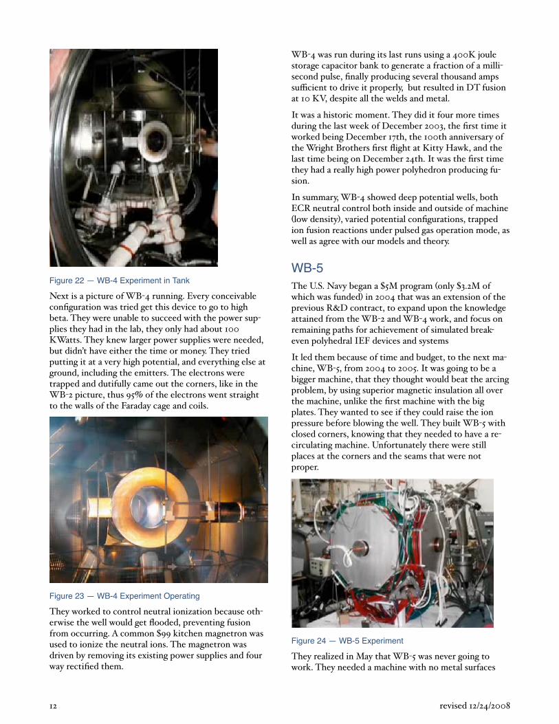
Figure 22 — WB-4 Experiment in Tank
Next is a picture of WB 4 running. Every conceivable configuration was tried get this device to go to high beta. They were unable to succeed with the power supplies they had in the lab, they only had about 100 KWatts. They knew larger power supplies were needed, but didn’t have either the time or money. They tried putting it at a very high potential, and everything else at ground, including the emitters. The electrons were trapped and dutifully came out the corners, like in the WB 2 picture, thus 95 of the electrons went straight to the walls of the Faraday cage and coils.
Figure 23 — WB-4 Experiment Operating
They worked to control neutral ionization because otherwise the well would get flooded, preventing fusion from occurring. A common 99 kitchen magnetron was used to ionize the neutral ions. The magnetron was driven by removing its existing power supplies and four way rectified them.
WB 4 was run during its last runs using a 400K joule storage capacitor bank to generate a fraction of a millisecond pulse, finally producing several thousand amps su cient to drive it properly, but resulted in DT fusion at 10 KV, despite all the welds and metal.
It was a historic moment. They did it four more times during the last week of December 2003, the first time it worked being December 17th, the 100th anniversary of the Wright Brothers first flight at Kitty Hawk, and the last time being on December 24th. It was the first time they had a really high power polyhedron producing fusion.
In summary, WB 4 showed deep potential wells, both ECR neutral control both inside and outside of machine low density , varied potential configurations, trapped
ion fusion reactions under pulsed gas operation mode, as well as agree with our models and theory.
WB-5The U.S. Navy began a 5M program only 3.2M of which was funded in 2004 that was an extension of the previous R&D contract, to expand upon the knowledge attained from the WB 2 and WB 4 work, and focus on remaining paths for achievement of simulated breakeven polyhedral IEF devices and systems
It led them because of time and budget, to the next machine, WB 5, from 2004 to 2005. It was going to be a bigger machine, that they thought would beat the arcing problem, by using superior magnetic insulation all over the machine, unlike the first machine with the big plates. They wanted to see if they could raise the ion pressure before blowing the well. They built WB 5 with closed corners, knowing that they needed to have a recirculating machine. Unfortunately there were still places at the corners and the seams that were not proper.
Figure 24 — WB-5 Experiment
They realized in May that WB 5 was never going to work. They needed a machine with no metal surfaces
12 revised 12/24/2008
available to the electrons to enable it to be recirculating. All the coil containers have to be conformal to the magnetic fields they produce.
So they built another machine in great haste since they were running out of money. Their budget had run out in fiscal 2005 the entire Navy Energy Program was cut to zero , and they were going to have to terminate sta and start closing down our laboratory in April. But they were saved by Admiral Cohen who gave them an 900K survival money infusion to carry them through fiscal 2005, to the point where they were forced to shut down..
The WB 5a device had circular torroidal coils that were spaced at the corners. The key is the spacing. The original patent was based on the idea that you have coils that have zero dimension, a brilliant physics idea. But the minute you have a coil with finite thickness and try to put them together, the coils and currents on one coil, interact with the coils and currents adjacent to them. You can’t have those coils touching, otherwise the field lines will run into the metal. They had to space the coils so there was room for the magnetic fields to go out. And the spacing has to be a certain number of gyro radius.
They built WB 5a like this, but the connectors remained as problems. They built it in July and August 2005, ran it in August and September 2005, and early October, to get
= 1 data. Then we ran it in November 2005.
The following image shows how WB 5a looked when it finally went in a vacuum tank.
In summary, WB 5 showed deep potential wells, potential well formation, fusion and oscillatory well collapse arising from limited power supply current capability, and the performance limits of closed configuration.
WB-62005 saw the operation of the WB 6, it worked like a champ. It did everything they imagined it should have done in the beginning. For 15 years, none of their consultants, review board members, opponents, Dr. Bussard, or his sta , had seen the problem of electrons grounding themselves on the metal surfaces of the machines.
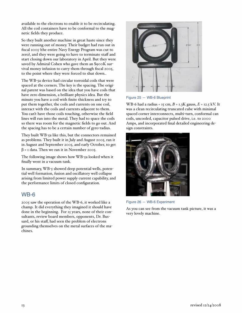
Figure 25 — WB-6 Blueprint
WB 6 had a radius = 15 cm, B = 1.3K gauss, E = 12.5 kV. It was a clean recirculating truncated cube with minimal spaced corner interconnects, multi turn, conformal can coils, uncooled, capacitor pulsed drive, i.e. to 2000 Amps, and incorporated final detailed engineering design constraints.
Figure 26 — WB-6 Experiment
As you can see from the vacuum tank picture, it was a very lovely machine.
13 revised 12/24/2008
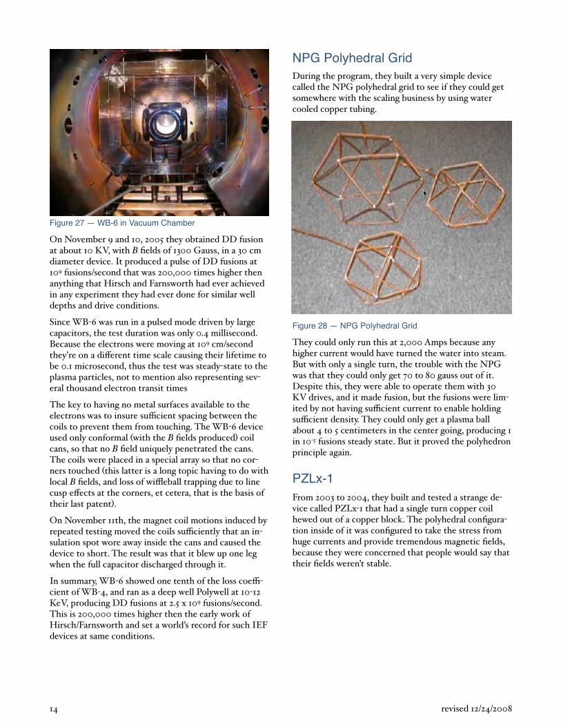
Figure 27 — WB-6 in Vacuum Chamber
On November 9 and 10, 2005 they obtained DD fusion at about 10 KV, with B fields of 1300 Gauss, in a 30 cm diameter device. It produced a pulse of DD fusions at 109 fusions/second that was 200,000 times higher then anything that Hirsch and Farnsworth had ever achieved in any experiment they had ever done for similar well depths and drive conditions.
Since WB 6 was run in a pulsed mode driven by large capacitors, the test duration was only 0.4 millisecond. Because the electrons were moving at 109 cm/second they’re on a di erent time scale causing their lifetime to be 0.1 microsecond, thus the test was steady state to the plasma particles, not to mention also representing several thousand electron transit times
The key to having no metal surfaces available to the electrons was to insure su cient spacing between the coils to prevent them from touching. The WB 6 device used only conformal with the B fields produced coil cans, so that no B field uniquely penetrated the cans. The coils were placed in a special array so that no corners touched this latter is a long topic having to do with local B fields, and loss of wi eball trapping due to line cusp e ects at the corners, et cetera, that is the basis of their last patent .
On November 11th, the magnet coil motions induced by repeated testing moved the coils su ciently that an insulation spot wore away inside the cans and caused the device to short. The result was that it blew up one leg when the full capacitor discharged through it.
In summary, WB 6 showed one tenth of the loss coecient of WB 4, and ran as a deep well Polywell at 10 12 KeV, producing DD fusions at 2.5 x 10⁹ fusions/second. This is 200,000 times higher then the early work of Hirsch/Farnsworth and set a world’s record for such IEF devices at same conditions.
NPG Polyhedral GridDuring the program, they built a very simple device called the NPG polyhedral grid to see if they could get somewhere with the scaling business by using water cooled copper tubing.
Figure 28 — NPG Polyhedral Grid
They could only run this at 2,000 Amps because any higher current would have turned the water into steam. But with only a single turn, the trouble with the NPG was that they could only get 70 to 80 gauss out of it. Despite this, they were able to operate them with 30 KV drives, and it made fusion, but the fusions were limited by not having su cient current to enable holding su cient density. They could only get a plasma ball about 4 to 5 centimeters in the center going, producing 1 in 10 5 fusions steady state. But it proved the polyhedron principle again.
PZLx-1From 2003 to 2004, they built and tested a strange device called PZLx 1 that had a single turn copper coil hewed out of a copper block. The polyhedral configuration inside of it was configured to take the stress from huge currents and provide tremendous magnetic fields, because they were concerned that people would say that their fields weren’t stable.
14 revised 12/24/2008
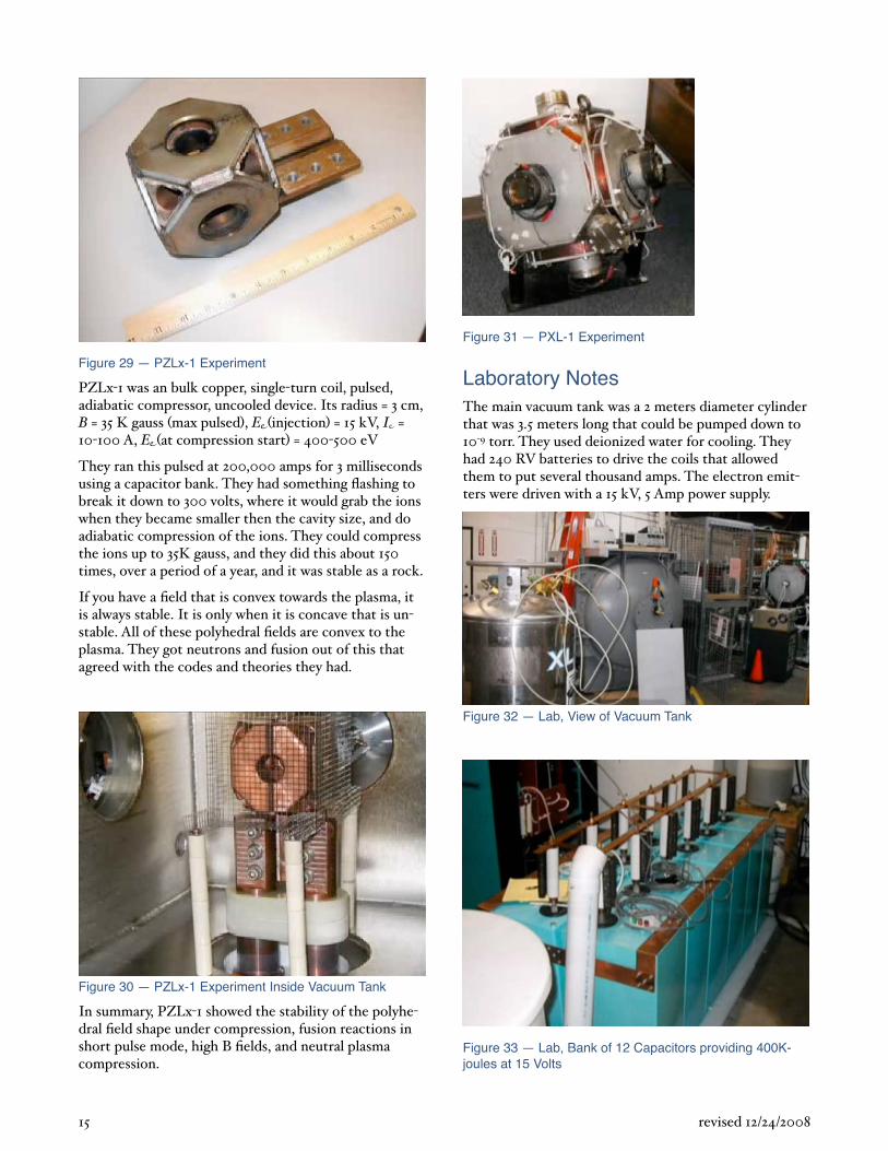
Figure 29 — PZLx-1 Experiment
PZLx 1 was an bulk copper, single turn coil, pulsed, adiabatic compressor, uncooled device. Its radius = 3 cm, B = 35 K gauss max pulsed , E injection = 15 kV, I = 10 100 A, E at compression start = 400 500 eV
They ran this pulsed at 200,000 amps for 3 milliseconds using a capacitor bank. They had something flashing to break it down to 300 volts, where it would grab the ions when they became smaller then the cavity size, and do adiabatic compression of the ions. They could compress the ions up to 35K gauss, and they did this about 150 times, over a period of a year, and it was stable as a rock.
If you have a field that is convex towards the plasma, it is always stable. It is only when it is concave that is unstable. All of these polyhedral fields are convex to the plasma. They got neutrons and fusion out of this that agreed with the codes and theories they had.
Figure 30 — PZLx-1 Experiment Inside Vacuum Tank
In summary, PZLx 1 showed the stability of the polyhedral field shape under compression, fusion reactions in short pulse mode, high B fields, and neutral plasma compression.
Figure 31 — PXL-1 Experiment
Laboratory NotesThe main vacuum tank was a 2 meters diameter cylinder that was 3.5 meters long that could be pumped down to 10 9 torr. They used deionized water for cooling. They had 240 RV batteries to drive the coils that allowed them to put several thousand amps. The electron emitters were driven with a 15 kV, 5 Amp power supply.
Figure 32 — Lab, View of Vacuum Tank
Figure 33 — Lab, Bank of 12 Capacitors providing 400K-joules at 15 Volts
15 revised 12/24/2008
Results and ConclusionsIncreasing Neutral Gas DensityThe following graph shows the potential well as a function of the density of the starting neutral gas. The DARPA HEPS 190 cm data is shown on the left.
0.8
0.6
0.4
0.2
0 10-410-510-610-710-810-910-10
Fwell
Density
WB-5 HEPS
Figure 34 — Fwell vs. Density for HEPS and WB-5
If the starting pressure and density was somewhere between 1.0 and a 1.0 x 108 cm3 and we had to run this in 25 millisecond pulse mode that the potential well that was set up died because the pulse created ions out of the neutrals. The ions would immediately see the well, rush in and flood the well, and blow it out. It couldn’t be stopped because we didn’t have steady state control. We didn’t have the budget or the money to develop the necessary controls.
We initially had 30M, then the DARPA director changed four months after it started. He said, “We don’t do fusion in DARPA”, so he killed our remaining budgeted money. But we went ahead and built what we started out to build.
On the right part of the graph shows what happened when we built WB 5. We were able to move the starting pressure at which the well died up by a factor of a thousand. We said, “oh, boy, we’re winning!” But we need to go to where the pressure is about a hundred times higher then WB 5 to get the densities high enough to make useful fusion. We just needed to get a hundred times more current in it. So we thought, hey, we have this capacitor bank, we can put that current into it for a short while, so we did. We put a factor 100 times more current into the magnets, but only got a factor of 2 improvement in ion pressure.
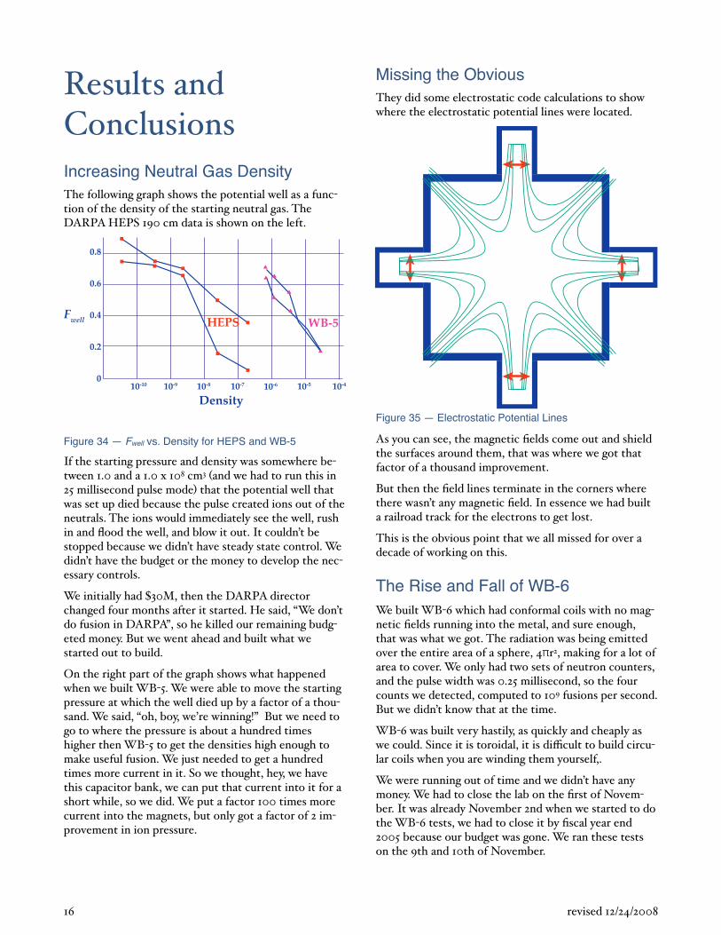
Missing the ObviousThey did some electrostatic code calculations to show where the electrostatic potential lines were located.
Figure 35 — Electrostatic Potential Lines
As you can see, the magnetic fields come out and shield the surfaces around them, that was where we got that factor of a thousand improvement.
But then the field lines terminate in the corners where there wasn’t any magnetic field. In essence we had built a railroad track for the electrons to get lost.
This is the obvious point that we all missed for over a decade of working on this.
The Rise and Fall of WB-6We built WB 6 which had conformal coils with no magnetic fields running into the metal, and sure enough, that was what we got. The radiation was being emitted over the entire area of a sphere, 4 r2, making for a lot of area to cover. We only had two sets of neutron counters, and the pulse width was 0.25 millisecond, so the four counts we detected, computed to 109 fusions per second. But we didn’t know that at the time.
WB 6 was built very hastily, as quickly and cheaply as we could. Since it is toroidal, it is di cult to build circular coils when you are winding them yourself,.
We were running out of time and we didn’t have any money. We had to close the lab on the first of November. It was already November 2nd when we started to do the WB 6 tests, we had to close it by fiscal year end 2005 because our budget was gone. We ran these tests on the 9th and 10th of November.
16 revised 12/24/2008
The problem was that we had run WB 6 quite a lot at lower voltages and higher densities to study = 1 configurations, running it on a high current, low voltage power supply. We would run it 50 or 100 times to get su cient data for the transfer equations.
Each time you turned a coil on, the magnetic forces in the wires tended to push them apart; they had been moved a lot in those tests. We ran WB 6 on the 9th and 10th of November, four times, and got these neutron results.
On November 11th, we tried running WB 6 at a much higher voltage and drive. The coils had moved suciently they were just normal coils covered with varnish insulation that at one corner they had worn through the varnish and shorted at the feed through. When the battery bank discharged through the coils, it blew the machine apart.
Closing the LabThat was 11 days past the shutdown of the laboratory, and on the following Monday we started to tear the lab down. Nobody had time to reduce the data that was stored on the computer. It wasn’t until early December that we reduced the data and looked at it, and realized what we had done, beating H&F by 100,000.
Once we knew that, what do you do, since nobody seemed to care? We closed the lab and put all the equipment together, and the woman who was the president of EMC2, said, “why don’t we save the equipment?” We can’t save it, we have a 1 million of Navy equipment sitting there. She said, “can you find a company locally that we can transfer the equipment to them as a DOD contractor?”
Dr. Bussard knew a man who was running a company like that, 10 minutes away from them, Jim Benson at SpaceDev in San Diego who had built the engines for Spaceship One.
He had known him for 30 years, a very bright guy, who is absolutely intent on making fusion power happen for space flight that was Dr. Bussard’s original goal, since it makes tremendous engines if it works.
They got together with Jim Benson and transfered all the vacuum pumps, tanks, and power supplies in the laboratory to him, who also hired their three best laboratory people.
17 revised 12/24/2008
SummaryEMC2 spent 12 years with 5 to 10 people working on 1/8 to 1/10 scale models to prove and validate the physics and associated engineering physics constraints, scaling laws, et cetera of IEC devices that use quasi spherical magnetic fields.
It is critical that no metal surface penetrated by the magnetic fields occupy more then 10 4 to 10 5 of the total surface available to the recirculating electrons. If this dead fraction is larger, there is NO hope of obtaining net power from such designs since it is essential that electrons be able to recirculate out and back through the cusps all over the machine. About 100,000 electron circuits are needed before being lost to a collision with the structure in order to obtain net power.
Their IEC device has the property that the electron flow and losses are decoupled from the ion flow and fusion generation. Power balance depends on suppression of the electron losses, which are derived from the energetic electron injection that forms the grid less negative potential well that traps the ions.
EMC2 AccomplishmentsSpecific accomplishments by EMC2 included:
• High energy potential well depth
• Ion focussing and trapping
• Fusion reactions
• Electron trapping
• Electron MG transport loss scaling
• Cusp loss mechanisms
• Well and field macro stability
• Neutral gas wall reflux suppression
• Limiting configurations and detailed design constraints for minimal losses
• Computer code design ability for machine B and E fields
• Fusion/electric power systems design codes
• World’s record DD fusion output in final experiments
• Determined and verified all design scaling laws for physics and engineering constraints
• Definition of RDT&E for full scale net power demonstration
• Prototype development plans
• Schedules and costs
PapersDr. Robert Bussard wrote a paper16 that was submitted to the 57th International Astronautical Conference www.aiaa.org held October 2 6. 2006 in Valencia,
Spain, with 1500 people attending from 150 nations. The paper discussed what they did, what they learned, and what it is all about. It is not a physics paper that provides all the equations and theories. The end of the paper provides many references.
He hope to begin writing a very long, 120 page paper on some of the mathematics in the near future.
18 revised 12/24/2008
16 “The Advent of Clean Nuclear Fusion: Superperformance Space Power and Propulsion,” Robert W. Bussard, 57th International Astronautical Congress IAC 2006
Proposed Demonstration ProgramEngineering IssuesWhile all of the fundamental physics issues have been identified, there are many key engineering issues that will need to be addressed:
• Instrumentation and control: the best way to provide ion and electron feeds
• Central anode height
• Drive current/voltage
• Magnetic field drive
• Associated diagnostics
• Machine structure and cooling
• Magnet cooling or super conducting supplies
• Vacuum exhaust system and separation
• Total system design and operation
Machine ScalingThere is no point in building anything half size. There are two scaling factors involved in this type of device: the power output scales as the seventh power of the size, and the power gain as the fifth power of the size.
There is little to be gained by building a half size model; it is too weak to give anything definitive about power production or gain.
A full scale fusion test machine will have approximately a 3 meter diameter, use 15K to 25K gauss magnetic fields, drive energies up to 180 KV, and produce 40 MWatts power.
Demonstration Costs and ActivitiesIt will take four to five years to implement the following full scale demonstration plan:
• 150 to 200M DD fusion
• 200 to 250M for p + 11B fusion no neutrons
Activities for the first year will cost 2M and will include:
• Two small test machines, WB 7 and WB 8
• Major high level review panel
• Demonstration program plan development
The WB 7 truncated cub machine is intended to be an improved and better version of WB 6 that should give 3 to 5 times more output, during which 50 tests will be run to validate its performance. WB 8 will be similar to WB8 except it will be a truncated decahedron machine.
The high level panel of experts will review the WB 7 and WB 8 work and will provide a recommendation either against or for proceeding with a full scale demonstration capable of generating power that will cost
200M.
The second and third year will require:
• Developing test site / facility
• Design and building first main test machines
• Test key engineering issues
The last two years of the demonstration project will result in building and testing the demonstration fusion plant.
19 revised 12/24/2008
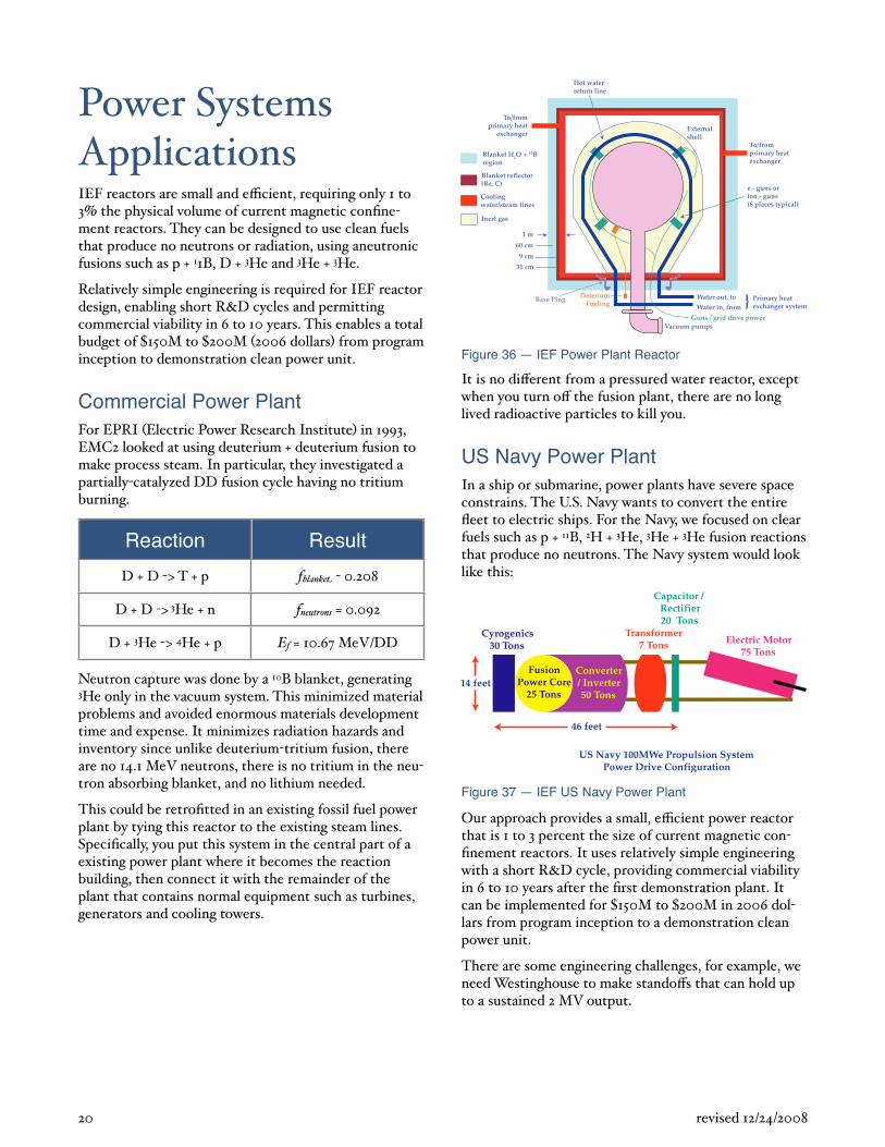
Power Systems ApplicationsIEF reactors are small and e cient, requiring only 1 to 3 the physical volume of current magnetic confinement reactors. They can be designed to use clean fuels that produce no neutrons or radiation, using aneutronic fusions such as p + 11B, D + 3He and 3He + 3He.
Relatively simple engineering is required for IEF reactor design, enabling short R&D cycles and permitting commercial viability in 6 to 10 years. This enables a total budget of 150M to 200M 2006 dollars from program inception to demonstration clean power unit.
Commercial Power PlantFor EPRI Electric Power Research Institute in 1993, EMC2 looked at using deuterium + deuterium fusion to make process steam. In particular, they investigated a partially catalyzed DD fusion cycle having no tritium burning.
Reaction Result
D + D > T + p fblanke 0.208
D + D > 3He + n fneutrons = 0.092
D + 3He > 4He + p Ef = 10.67 MeV/DD
Neutron capture was done by a 10B blanket, generating 3He only in the vacuum system. This minimized material problems and avoided enormous materials development time and expense. It minimizes radiation hazards and inventory since unlike deuterium tritium fusion, there are no 14.1 MeV neutrons, there is no tritium in the neutron absorbing blanket, and no lithium needed.
This could be retrofitted in an existing fossil fuel power plant by tying this reactor to the existing steam lines. Specifically, you put this system in the central part of a existing power plant where it becomes the reaction building, then connect it with the remainder of the plant that contains normal equipment such as turbines, generators and cooling towers.
DeteriumFueling
Water out, to
Water in, from
Blanket H2O + 10Bregion
Blanket reflector(Be, C)
Coolingwater/steam lines
Inert gas
To/fromprimary heat
exchanger
To/fromprimary heatexchanger
Externalshell
Hot waterreturn line
e - guns orion - guns(6 places typical)
Primary heatexchanger system
Guns / grid drive powerVacuum pumps
}
1 m
60 cm
9 cm
31 cm
Base Plug
Figure 36 — IEF Power Plant Reactor
It is no di erent from a pressured water reactor, except when you turn o the fusion plant, there are no long lived radioactive particles to kill you.
US Navy Power PlantIn a ship or submarine, power plants have severe space constrains. The U.S. Navy wants to convert the entire fleet to electric ships. For the Navy, we focused on clear fuels such as p + 11B, 2H + 3He, 3He + 3He fusion reactions that produce no neutrons. The Navy system would look like this:
����������������
�� �������!�"�������#$������
���������������%�����
&'����
(��)��*�+$$������ ��������*����������,���������-�������
�*��-�����.$�����
+&�������������!���������%$�����
/���������������#%�����
Figure 37 — IEF US Navy Power Plant
Our approach provides a small, e cient power reactor that is 1 to 3 percent the size of current magnetic confinement reactors. It uses relatively simple engineering with a short R&D cycle, providing commercial viability in 6 to 10 years after the first demonstration plant. It can be implemented for 150M to 200M in 2006 dollars from program inception to a demonstration clean power unit.
There are some engineering challenges, for example, we need Westinghouse to make stando s that can hold up to a sustained 2 MV output.
20 revised 12/24/2008
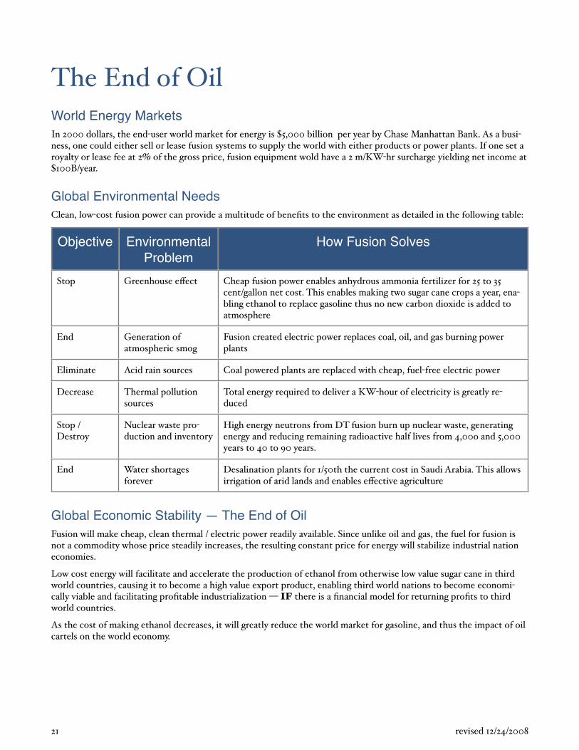
The End of OilWorld Energy MarketsIn 2000 dollars, the end user world market for energy is 5,000 billion per year by Chase Manhattan Bank. As a business, one could either sell or lease fusion systems to supply the world with either products or power plants. If one set a royalty or lease fee at 2 of the gross price, fusion equipment wold have a 2 m/KW hr surcharge yielding net income at
100B/year.
Global Environmental NeedsClean, low cost fusion power can provide a multitude of benefits to the environment as detailed in the following table:
Objective Environmental Problem
How Fusion Solves
Stop Greenhouse e ect Cheap fusion power enables anhydrous ammonia fertilizer for 25 to 35 cent/gallon net cost. This enables making two sugar cane crops a year, enabling ethanol to replace gasoline thus no new carbon dioxide is added to atmosphere
End Generation of atmospheric smog
Fusion created electric power replaces coal, oil, and gas burning power plants
Eliminate Acid rain sources Coal powered plants are replaced with cheap, fuel free electric power
Decrease Thermal pollution sources
Total energy required to deliver a KW hour of electricity is greatly reduced
Stop / Destroy
Nuclear waste production and inventory
High energy neutrons from DT fusion burn up nuclear waste, generating energy and reducing remaining radioactive half lives from 4,00o and 5,000 years to 40 to 90 years.
End Water shortages forever
Desalination plants for 1/50th the current cost in Saudi Arabia. This allows irrigation of arid lands and enables e ective agriculture
Global Economic Stability — The End of OilFusion will make cheap, clean thermal / electric power readily available. Since unlike oil and gas, the fuel for fusion is not a commodity whose price steadily increases, the resulting constant price for energy will stabilize industrial nation economies.
Low cost energy will facilitate and accelerate the production of ethanol from otherwise low value sugar cane in third world countries, causing it to become a high value export product, enabling third world nations to become economically viable and facilitating profitable industrialization IF there is a financial model for returning profits to third world countries.
As the cost of making ethanol decreases, it will greatly reduce the world market for gasoline, and thus the impact of oil cartels on the world economy.
21 revised 12/24/2008
QuestionsMetastatic materials have strange indexes of r
action. Wi this give us any hope in doing magnetic confinement?
I don’t think so, it has nothing to do with their properties, they are just in another world that we don’t interact with. Everything that we are doing is at enormously high magnetic fields, it is a very hostile environment, very hot with energetic particle, in the case of p + 11B, particles at 200 keV, causing huge surface damage from impacts, so I don’t see how these solid state devices will have any role to play in the machine. However they might have some role in external control systems.
What would it take to rebuild the WB 6?
That would be the first year of our program, the WB 7 and WB 8 machines. They are similar to WB 6, but would not use circular coils, rather they will use coils that follow the polyhedral configuration, but will be carefully spaced, and we expect them to work 3 to 5 times better then WB 6.
WB 7 will be a truncated cube, and WB 8 will be a truncated decahedron. Our hope to be provide 50 times better performance then WB 6, so the senior review board will have something to look at, i.e. we wouldn’t hold the review board until we had the test run data for them to review. This will take 2 million. But you really should program the overall five year program, so you can get some run up on the following years to come.
What other information is available?
I hope to get to be writing a very long, 120 page paper on some of the mathematics. There is also the paper that was recently published in the 57th International Astronautical Conference held at Valencia, Spain in October 2006.
In steady state, how do you actua y extract the eergy om the helium atoms?
When you do p + 11B, you get three helium nuclei at various energies. You have external, electrically biased grids. When the helium atoms hit a grid, they become neutral. It is like a giant beta decay battery. You have an external pumping exhaust system that gathers all the gas because you can’t a ord to lose the boron fuel, using separation systems to separate the helium from the boron. We did a study for Los Alamos looking at centrifuges and electromagnetic separation. It is very straightforward, since these are all light elements, yet the relative di erences are quite sizable, and they condense at di erent temperatures.
Other then engineering, what other cha enges rmain?
You need really good people. You need expertise and assistance from companies like Westinghouse, GE, and Raytheon. For example, if you want 200 kV stando s, you need someone like Westinghouse to design and build them. But the major impediment has always been money. Since 1989 we’ve told the Navy and the Department of Defense that the cost of this program in today’s dollars is 200M, in report after report after report. They’ve known this from the beginning.
But they say, we can’t do that. Because if we do that, it becomes visible to the sta ers on Capital Hill. Then everyone becomes aware that this is what the Navy is doing. The Department of Energy will see it. Everyone will say, no, you can’t do that. We have the charter to do fusion. And that is the end of the program. Because they will co opt it and shut the Navy down.
So we got funded at a level below the radar level and politics. The funding has always been way too small. We had a sta of 5 to 10 people working for 12 years. The result was that we learned all the physics slowly, but we learned it all. And the engineering problems are way beyond those budgets. We couldn’t run the machine steady state, we had to use small coils and capacitor banks. That made things very di cult. You don’t have time, you have problems with cooling, you can’t control the gas flow we had 7 millisecond gas pulses that we couldn’t turn o in time . It is much easier to build a big machine from a control problem. Who ever does this will need a lot of help.
You said that a lot of the people in this area are over 70 years old. That seems like a problem.
I made a rather jocular remark that most of the people on the review board would be in their 70s. There will be some people in their 30s, since I know some very bright people. The problem is that engineering, nuclear engineering, and related physics schools, don’t train people in this field anymore. They haven’t for 20 or 25 years, because it is an archaic field that doesn’t fit modern technology; we’ve all gone to silicon, microchips, and solid state devices.
There are very few companies who make giant, four foot high tubes. It is not like the days of Nikola Tesla; its really back in that world. It’s not that anyone is evil, it is just that there wasn’t any market for people like that. So the people that lived through that, I’ll give you one example, one guy I’d like on the review board is Bob Simons. He was head of research at Varian Associates, then was head of Litton Electron Devices in San Carlos, CA. He’s been working in this field and following it for 35 years. He’s 86 years old, but is smart as a tack. He comes from another world. There is no one trained in the schools that you can turn to.
I know some good people at Sandia and Los Alamos that are really bright, for this panel because they think out of
22 revised 12/24/2008
the conventional, magnetic confinement box. And that is the problem. The box has become so big and so well funded, with thousands of people in labs all over the world that everyone for decades has been thinking about Maxwellian plasmas, and it is very hard to break that mindset. If you live in that box, and your income comes from doing research in that box, how do you ever break out of it? Well, I know of a few people who can.
It is a very di cult problem that I discussed with Bob Hirsch in Alexandra, Virginia. I asked him, “Where can we find people, particularly those that are credible?” You can find a lot of people over 65 who are really credible, who have been brilliant engineers in their lifetime, who have national and international stature, who I trust. I don’t own these guys, they are just friends of mine who don’t lie to me. They would tell me what they really think. I want to get the brightest guys I know to tell me what they really think Should we go ahead, or is it too big a risk?
Where are you looking for funding?
We’ve given up on the government in the sense that we can’t find anyone that is remotely interested in doing it. The government is run largely by people without a physics background. And many of the sta ers that support them, don’t really have one either. We are doing very complex and archaic physics. This is not a fault, it is just the way things are. The government will always turn to its government labs for an assessment. And the labs will say, “no good.” I’ve been through this for so many years, it is beyond belief. These are my labs, I used to be an assistant director of Los Alamos and the AEC. I know these guys, they’re all going to say, “No,” except for a handful of guys in those labs who think outside the box.
What about the possibility of using computer simulations to advance some of the state of the art here?
We have been doing computer simulations since 1989, starting with Bruce Goplin at Mission Research <www.mrcwdc.com> using their Magic Code which was a particle and cell code from which we could make beautiful movies of these little particles moving in and out. We did numerics with Jack Watkins in Albuquerque, New Mexico doing more particles and cells, but halfway through their contract, they said, “We give up.” They couldn’t calculate the problem. How do you do a calculation for a magnetic field expanding towards the beta = 1 condition, and the pressure balance calculation in a transient sort of way, with all these Maxwellian interconnections, when you are only one part in a million from quasi neutrality? They couldn’t make the grid small enough to eliminate the numeric noise for the one part in a million environments we were interested in; the calculations would have taken eons to run for such small grids. They quit.
We have a lot of numeric calculation capability code that was developed by an ex Sandia guy in Albuquerque and modified by him to some degree. It is a brilliant, wonderful code that was originally developed for particle beam accelerators, but the code only works in a collision less regimen. As soon as we get beyond a few hundred nanoseconds, we have collisions causing expansion of the B field. The code only helps us for startup conditions. Numeric simulation is great, but it has horrifying limitations due to the nature of the physics of the problem.
At DARPA, we were going to have five parallel processors working on this problem as part of a 8M e ort, but we never had the money.
What about financing?
We ran out of money because for the fiscal 2006 budget, the Navy R&D budget was cut 26 because of the Iraq conflict. The entire Advanced Energy Development line item was cut, and we were under that line item, so we had no money coming in. Rear Admiral Jay Cohen, Chief of Naval Research, Assistant Deputy Commandant for Science & Technology, saved us just enough to get our last results.
There is no way in the current budget situation with the ongoing Iraq conflict and current administration to get any money for anything other then 700 mile border security fences and such. There is no way that the Department of Energy will ever support it, or at least, not until it is running in China, because it is a threat to their existing 2M a day rice bowl. Everyone is running down the road to the ITER tokamak facility being built in Cadarache, France since they can do research for the next 20 and 30 years and retire.
I don’t see government doing it anywhere, in any Western nation. That is why I think it will only be done by a nation that is not part of the tokamak program. But for
40M a year, it can be done by a lot of di erent countries, and probably will be.
Do I have a plan for private money? No, I’m here by accident. Knowle called me and said, “Why don’t you come to Google and give a talk.” I knew something about Google, its people, and its stockholders, I think it has an exciting outlook, an interesting point of view, and a very exciting way of doing things around here, that I haven’t seen in a long time, and you have a lot of money. If there is any serious interest in changing the world, on a long time scale that isn’t going to return anything in two or three years, this may be a place that you might want to pay some attention. Obviously we need an angel.
There are many people in this country worth billions of dollars that could fund this at lunchtime. I have no intention of running around talking to them all. I’m too tired. If someone wants to do it, they’ll figure it out. If
23 revised 12/24/2008
they don’t, it will be in print, all over the world, and I’ll give it away. We have the patents on it. Someone will pick it up, somewhere. There are a lot of people in other countries that don’t have the mental constrains that we have in this country. While I would prefer that it be done in the United States, with people like Google who have vision and will power; I simply want it to happen.
My objective at age 7 was to fly to Mars, and I still want to do that today! Fusion power will enable a very remarkable space engine that is a thousand times better then anything else. It will enable a single stage rocket to Mars trip in four weeks. You can do HTOL to LEO horizontal take o and landing to low earth orbit for 25/kilogram. You can travel to Titan, a moon of Saturn,
in 76 days!
During the years that the U.S.Navy imposed an embargo o publishing EMC2 research, Dr. Bussard wrote 8 papers on how you could make space flight practical using fusion reactors. 17 1819
I wish I had a plan. I could tell you what a plan would be going to all the foundations, all the multi billionaires,
the people involved in Space X. But I’m too tired of talking to people. The problem is that the fusion community is so old and entrenched.
The question you immediately get when you talk to people who do not personally understand how the physics will work, they’ll say, “It sounds good, but I’ll have to have it vetted by someone.” They don’t know where to go.
The other initial question we get is, “How come, if it is so good, the United States government isn’t already doing it?” And it is not unreasonable question. The answer is very long and tedious and it sounds like sour grapes, but it is just reality. In private industry, where people don’t think like government, they can understand that. You do what you do because it is right and you try it. That is what you do here, I think.
Has anyone else reproduced the results?
No, we published it for the first time in October 2006.
The only other people working on this in the field are at the University of Illinois, George Miley <www.ne.uiuc.edu/miley.html> who is working on the Hirsch Farnsworth regime with grids, Gerald Kulcinski
and John Santarius at the University of Wisconsin <fti.neep.wisc.edu/iec/ftisite1.htm> where they have been working on Hirsch Farnsworth machines for a long time. They are all stuck with the grid systems. Nobody is trying to do the magnetic confinement system, possibly because we held all the patents on it. Not that it was stopping them from doing research.
I’ve known all these guys for 30 years. They are good guys, they just took a di erent path, trying to see if they could make Hirsch Farnsworth better. But they haven’t been able to. And there is a group in Japan doing some similar with Hirsch Farnsworth Professor Kiyoshi Yoshikawa at the Institute of Advanced Energy at Kyoto University . There is a man in Germany, John Sved, who is building semi cylindrical systems for neutron sources for measuring paper thickness in paper mills at NSDFusion, <www.nsd fusion.com>. But that’s not fusion power, it is making a diagnostic instrument. It is similar to oil well instrumentation where they use pulsed neutrons in oil fields to scatter o hydrocarbon deposits.
I don’t know anyone who is doing what we’ve done. That is a problem in forming the review committee; there is no group of people to turn to who have been working on it, except for people who worked on it 25 and 30 years ago.
Why did you choose to publish where you did?
Partly because I’m a Fellow of the Institute of Aeronautics, partly because I’m a space flight enthusiast, and partly because the meeting was being held at a time that coincided with my time schedule. I didn’t go to deliver the paper in Spain since there are certain medical limitations on what I can do.
I hope to publish a much larger paper in the Journal of Fusion Technology, but I haven’t written it yet. It is a daunting task to try and condense 11 years of work and hundreds of government technical reports. And who will review my paper once I’ve written it?
24 revised 12/24/2008
17 "From SSTO to Saturn's Moons, Superperformance Fusion Propulsion for Practical Spaceflight", R.W. Bussard and L. W. Jameson, 30th AIAA/ASME/SAE/ASEE Joint Propulsion Conference, 27 29 June 1994, AIAA 94 3269
18 “An advanced fusion energy system for outer planet space propulsion,” Robert W. Bussard, January 14, 2002, AIP Conference Proceedings Volume 608, Issue 1, Space technology and applications international forum, Albuquerque, New Mexico, pg. 768 779.
19 "Inertial Electrostatic Propulsion Spectrum: Airbreathing to Interstellar Flight", R.W. Bussard and L. W. Jameson, Journal of Propulsion and Power, volume 11, no 2.

About the Author
Mark Duncan is a marketing consultant who focuses on emerging technologies, assisting companies in entering new markets and developing new business opportunities. He can be contacted at [email protected].
25 revised 12/24/2008