shredding eagle - guitarpcb
TRANSCRIPT

Shredding Eagle When this Eagle sinks it’s Talons in, you’ll know you have reached SHREDDING territory! Board Dimensions (W x H) 2.15” x 1.95” (6) On-Board 16mm Right Angle Pots or Hand Wired, your choice.
Take a ride on this fabulous new OVERDRIVE and EQ combination. Go from clean, smooth overdrive to outrageous full blown SHREDDING tones that will blow your mind! SHREDDERS REJOICE!!! The SHREDDING EAGLE combines a high gain overdrive with a full 3 band active Baxandall EQ stage and even adds a versatile PRESENCE control to shape the tone into many different tones you could sink your Talons into.
Build Notes: * IC: TL072 – You may also try other Dual Opamps like NE5532, 4558, Burr Brown 2134 etc... ** D1 – D2 – Clipping LEDs – Try Red, Blue or Violet for a warm tube tone or you may also try our “hand tested” Germanium Diodes for a different character. Since the circuit uses a Baxandall Active EQ you will still have enough Gain on tap. Also feel free to try Silicon Diodes as well. Socket and See!

Bill of Materials
Part Value Part Value Part Value Part Value
R1 2M2 R12 10k C4 1u D1 **Clipping LED
R2 1k R13 10k C5 3n3 D2 **Clipping LED
R3 220k R14 10k C6 1u D3 1N4001
R4 4k7 R15 1k C7 4n7 D4 CA - Status LED
R5 1k R16 10k C8 4n7 IC *TL072
R6 1k R17 10k C9 22n VOL A100k
R7 2k2 R18 1k8 C10 22n GAIN A500k
R8 3k3 C11 2u2 BASS B50k
R9 10k C1 100p C12 100u MID B50k
R10 2k2 C2 100n C13 100u TREB B100k
R11 3k3 C3 100p IC1 *TL072 PRES B5k
Additional Build Notes: C6 and C11 have extra pads (XP1 & XP2) to accept either electrolytic capacitors or the preferred MLCC type. MLCC are non polar & take up less room in height & width. Only slightly more expensive but will last a lifetime. Choose MLCC with a 5mm lead spread (hence the extra XP Pads). I’ve hyperlinked choices below from Mouser.
GuitarPCB prefers MLCC capacitors for both sound quality, price and their small size. Potentiometer Wiring: You may use 16mm right angle pots or hand wire, your choice. If using our Anti-Static Pot Condoms as a protective and cushioned shield be careful not to push the leads in completely before soldering as you want the potentiometers to be even and level. We recommend drilling 5/16” min. slightly large to allow an easier fit and the Pot Condoms will compress or you may use an Exacto blade to trim of the sides of each Center Condom. The best option is to install the pots (with Pot Condoms) in the enclosure first before soldering them to the board. The board can then be removed for final testing, etc.. Potentiometer Sourcing: All required Potentiometer values of 16mm Right Angle potentiometer, may be purchased at Small Bear as well as the rest of them. In Europe they are also available at Das Musikding. If you are going to use In/Out Jacks that mount from the top we suggest Switchcraft #111 which can also be purchased at Small bear in the USA or Das Musikding in Europe.
Notes about the Tone Section: This stage is an active, true tone equalizer. Each band will boost or cut the signal. Start with each control in the center or 50% position. Turn the control clockwise, CW to BOOST and counter-clockwise, CCW to CUT the signal. After achieving the desired tone setting, adjust the final volume level to suit. As with all active equalizers, best results are usually achieved by cutting frequencies rather than over- boosting. There is some interaction between adjacent bands. This permits smooth transitions in the tonal setup. Combo Ultra Gain Mod: Add an AfterBlaster or Stage 3 Booster to your order which adds an extra transistor stage for those wanting even more out of this fantastic circuit. See Video. The amount of gain is also adjustable. The After Blaster volume control can be set with a trimmer for a set and forget gain boost that fits right over your footswitch with no extra enclosure controls. This is a Mod only. Mods do not come with kits. Disclosure: GuitarPCB is not affiliated with any of versions of this circuit that may be available commercially or any modified versions. This is our own take on a popular circuit. All copyrights, trademarks, and artworks remain the property of their owners. GuitarPCB.com claims no rights or affiliation to those names or owners.

STATUS LED D4 is a common anode bi-color LED. The diagram at right shows the pin-out, schematic symbol and pad connection for a common anode LED. The pin-out for the bi-color LED is typically (but not always) as follows: The lead 1 pad on the circuit board is marked with a white box. When connected correctly, the LED will light red when power is applied and the circuit is in bypass mode. The LED will light green when in effects mode. If you wish to use a standard LED, connect the anode to the middle pad and the cathode to the right pad to show the circuit in effects mode. If you use a 3PDT wiring board that includes an LED, you can omit this LED and R18. *R18 is the LED’s Current Limiting Resistor (CLR). If you use a different LED, you may want to change this value to adjust LED brightness. If you are using one of GuitarPCB’s handy 3PDT wiring boards, pads S4, S5, S6 and D8 would be ignored and R18 would not be installed. See wiring guide below for reference.
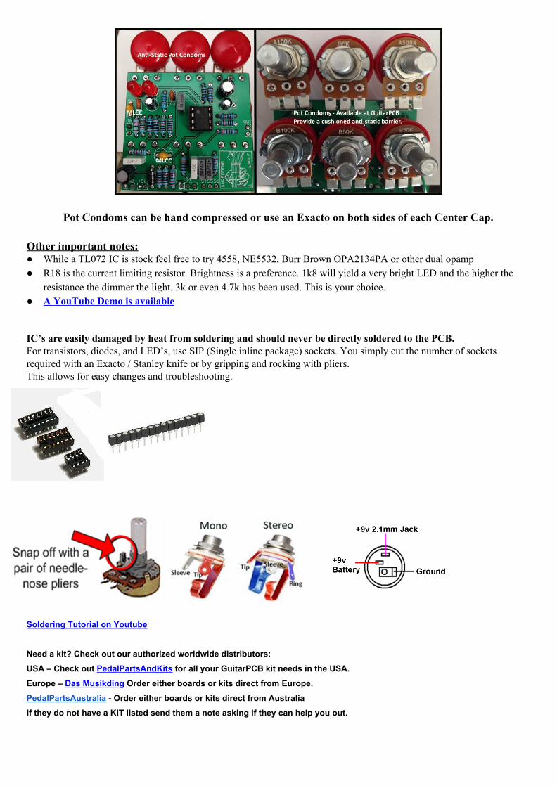
Pot Condoms can be hand compressed or use an Exacto on both sides of each Center Cap.
Other important notes: ● While a TL072 IC is stock feel free to try 4558, NE5532, Burr Brown OPA2134PA or other dual opamp ● R18 is the current limiting resistor. Brightness is a preference. 1k8 will yield a very bright LED and the higher the
resistance the dimmer the light. 3k or even 4.7k has been used. This is your choice. ● A YouTube Demo is available
IC’s are easily damaged by heat from soldering and should never be directly soldered to the PCB. For transistors, diodes, and LED’s, use SIP (Single inline package) sockets. You simply cut the number of sockets required with an Exacto / Stanley knife or by gripping and rocking with pliers. This allows for easy changes and troubleshooting.
Soldering Tutorial on Youtube
Need a kit? Check out our authorized worldwide distributors: USA – Check out PedalPartsAndKits for all your GuitarPCB kit needs in the USA. Europe – Das Musikding Order either boards or kits direct from Europe. PedalPartsAustralia - Order either boards or kits direct from Australia If they do not have a KIT listed send them a note asking if they can help you out.

Drill Template for Top Mounted Jacks – Switchcraft #111 recommended. Templates are customizable based on need. If you are using top mount In/Out Jacks we suggest Switchcraft #111 can also be purchased from Small Bear like the 16mm Right Angle On-Board Potentiometers. If you want side jacks try P.P.A.K.’s Mini Open Jacks. We recommend drilling Pot holes 5/16” minimum or 8mm to allow an easier fit of the Potentiometers. Drill at your own risk. Templates are only a guide. Print at 300 resolution.
We recommend drilling Pot holes 5/16” min. or 8mm to allow an easier fit and the Pot Condoms will compress or you may use an Exacto blade to trim of the sides of each Center Condom. The best option is to install the pots (with Pot Condoms) in the enclosure first before soldering them to the board. The board can then be removed for final testing, etc..
This document, PCB Artwork and Schematic Artwork © GuitarPCB.com. Schematic, PCB and this document by Bruce R. and Barry S. All copyrights, trademarks, and artworks remain the property of their owners. Distribution of this document is prohibited without written consent from GuitarPCB.com. GuitarPCB.com claims no rights or affiliation to those names or owners.