sht1x / sht7x humidity & temperature sensorpcbheaven.com/datasheet/sht1x_7x.pdfsht1x / sht7x...
TRANSCRIPT
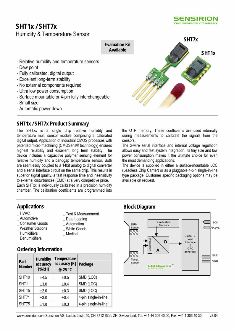
SHT1x / SHT7x Humidity & Temperature Sensor
SHT1x
Evaluation KiAvailable
- Relative humidity and temperature sensors - Dew point - Fully calibrated, digital output - Excellent long-term stability - No external components required - Ultra low power consumption - Surface mountable or 4-pin fully interchangeable- Small size - Automatic power down
SHT1x / SHT7x Product Summary The SHTxx is a single chip relative humidity and temperature multi sensor module comprising a calibrated digital output. Application of industrial CMOS processes with patented micro-machining (CMOSens® technology) ensures highest reliability and excellent long term stability. The device includes a capacitive polymer sensing element for relative humidity and a bandgap temperature sensor. Both are seamlessly coupled to a 14bit analog to digital converter and a serial interface circuit on the same chip. This results in superior signal quality, a fast response time and insensitivity to external disturbances (EMC) at a very competitive price. Each SHTxx is individually calibrated in a precision humidity chamber. The calibration coefficients are programmed into
the OTP memory. These coefficients are used internally during measurements to calibrate the signals from the sensors. The 2-wire serial interface and internal voltage regulation allows easy and fast system integration. Its tiny size and low power consumption makes it the ultimate choice for even the most demanding applications. The device is supplied in either a surface-mountable LCC (Leadless Chip Carrier) or as a pluggable 4-pin single-in-line type package. Customer specific packaging options may be available on request.
1
Applications _ HVAC _ Automotive _ Consumer Goods _ Weather Stations _ Humidifiers _ Dehumidifiers
Block Diagram
VDD
GND
SCK
DATA
Calibration Memory
14-bit
%RH Sensor
Digital 2-wire
Interface&
CRC generator
Am
plifi
catio
n
D
Temp. Sensor
A
Ordering InformationPart Number
Humidity accuracy
[%RH]
Temperature accuracy [K]
@ 25 °C Package
SHT10 ±4.5 ±0.5 SMD (LCC) SHT11 ±3.0 ±0.4 SMD (LCC) SHT15 ±2.0 ±0.3 SMD (LCC) SHT71 ±3.0 ±0.4 4-pin single-in-line SHT75 ±1.8 ±0.3 4-pin single-in-line
www.sensirion.com Sensirion AG, Laubisrütistr. 50, CH-8712 Stäfa ZH, Switze
SHT7x t
_ Test & Measurement _ Data Logging _ Automation _ White Goods _ Medical
rland, Tel: +41 44 306 40 00, Fax: +41 1 306 40 30 v2.04

SHT1x / SHT7x Relative Humidity & Temperature Sensor System
1 Sensor Performance Specifications
Parameter Conditions Min. Typ. Max. Units Humidity Resolution (2) 0.5 0.03 0.03 %RH 8 12 12 bit Repeatability ±0.1 %RH Accuracy (1)
Uncertainty linearized see figure 1
Interchangeability Fully interchangeable raw data ±3 %RH Nonlinearity linearized <<1 %RH
Range 0 100 %RH Response time 1/e (63%)
slowly moving air 4 s
Hysteresis ±1 %RH Long term stability typical < 0.5 %RH/yr Temperature
0.04 0.01 0.01 °C 0.07 0.02 0.02 °F
Resolution (2)
12 14 14 bit ±0.1 °C Repeatability ±0.2 °F
Accuracy see figure 1 -40 123.8 °C Range -40 254.9 °F
Response Time 1/e (63%) 5 30 s Table 1 Sensor Performance Specifications
2 Interface Specifications
SHT1x(slave)
uC(master)
DATA
SCK
Vdd 2.4 - 5.5V
GNDVdd
Figure 2 Typical application circuit
2.1 Power Pins The SHTxx requires a voltage supply between 2.4 and 5.5 V. After powerup the device needs 11ms to reach its “sleep” state. No commands should be sent before that time. Power supply pins (VDD, GND) may be decoupled with a 100 nF capacitor.
2.2 Serial Interface (Bidirectional 2-wire) The serial interface of the SHTxx is optimized for sensor readout and power consumption and is not compatible with I2C interfaces, see FAQ for details. (1) Each SHTxx is tested to be fully within RH accuracy specifications at 25 °C (7(2) The default measurement resolution of 14bit (temperature) and 12bit (humidity
www.sensirion.com v2.04 May
Figure 1 Rel. Humidity, Temperature and Dewpoint accuracies
2.2.1 Serial clock input (SCK) The SCK is used to synchronize the communication between a microcontroller and the SHTxx. Since the interface consists of fully static logic there is no minimum SCK frequency.
2.2.2 Serial data (DATA) The DATA tristate pin is used to transfer data in and out of the device. DATA changes after the falling edge and is valid on the rising edge of the serial clock SCK. During transmission the DATA line must remain stable while SCK is high. To avoid signal contention the microcontroller should only drive DATA low. An external pull-up resistor (e.g. 10 kΩ ) is required to pull the signal high. (See Figure 2) Pull-up resistors are often included in I/O circuits of microcontrollers. See Table 5 for detailed IO characteristics.
7 °F) and 48 °C (118.4 °F) ) can be reduced to 12 and 8 bit through the status register.
2005 2/9

SHT1x / SHT7x Relative Humidity & Temperature Sensor System
2.2.3 Sending a command To initiate a transmission, a “Transmission Start” sequence has to be issued. It consists of a lowering of the DATA line while SCK is high, followed by a low pulse on SCK and raising DATA again while SCK is still high.
DATA
SCK
Figure 3 "Transmission Start" sequence
The subsequent command consists of three address bits (only “000” is currently supported) and five command bits. The SHTxx indicates the proper reception of a command by pulling the DATA pin low (ACK bit) after the falling edge of the 8th SCK clock. The DATA line is released (and goes high) after the falling edge of the 9th SCK clock.
Table 2 SHTxx list of commands
2.2.4 Measurement sequence (RH and T) After issuing a measurement command (‘00000101’ for RH, ‘00000011’ for Temperature) the controller has to wait for the measurement to complete. This takes approximately 11/55/210 ms for a 8/12/14bit measurement. The exact time varies by up to ±15% with the speed of the internal oscillator. To signal the completion of a measurement, the SHTxx pulls down the data line and enters idle mode. The controller must wait for this “data ready” signal before restarting SCK to readout the data. Measurement data is stored until readout,
therefore the controller can continue with other tasks and readout as convenient. Two bytes of measurement data and one byte of CRC checksum will then be transmitted. The uC must acknowledge each byte by pulling the DATA line low. All values are MSB first, right justified. (e.g. the 5th SCK is MSB for a 12bit value, for a 8bit result the first byte is not used). Communication terminates after the acknowledge bit of the CRC data. If CRC-8 checksum is not used the controller may terminate the communication after the measurement data LSB by keeping ack high. The device automatically returns to sleep mode after the measurement and communication have ended. Warning: To keep self heating below 0.1 °C the SHTxx should not be active for more than 10% of the time (e.g. max. 2 measurements / second for 12bit accuracy).
2.2.5 Connection reset sequence If communication with the device is lost the following signal sequence will reset its serial interface: While leaving DATA high, toggle SCK 9 or more times. This must be followed by a “Transmission Start” sequence preceding the next command. This sequence resets the interface only. The status register preserves its content.
DATA
SCK
Transmission Start
1 2 3 4 -8 9
Figure 4 Connection reset sequence
Command Code Reserved 0000x Measure Temperature 00011 Measure Humidity 00101 Read Status Register 00111 Write Status Register 00110 Reserved 0101x-1110x Soft reset, resets the interface, clears the status register to default values wait minimum 11 ms before next command
11110
2.2.6 CRC-8 Checksum calculation The whole digital transmission is secured by a 8 bit checksum. It ensures that any wrong data can be detected and eliminated. Please consult application note “CRC-8 Checksum Calculation” for information on how to calculate the CRC.
Figure 5 Example RH measurement sequence for value “0000’1001 ’ 0011’0001”= 2353 = 75.79 %RH (without temperature compensation)
www.sensirion.com v2.04 May 2005 3/9

SHT1x / SHT7x Relative Humidity & Temperature Sensor System
Figure 6 Overview of Measurement Sequence (TS = Transmission Start)
2.3 Status Register Some of the advanced functions of the SHTxx are available through the status register. The following section gives a brief overview of these features. A more detailed description is available in the application note “Status Register”
Figure 7 Status Register Write
Figure 8 Status Register Read
Bit Type Description Default 7 reserved 0 6 R End of Battery (low voltage detection)
‘0’ for Vdd > 2.47 ‘1’ for Vdd < 2.47
X No default value, bit is only updated after a measurement
5 reserved 0 4 reserved 0 3 For Testing only, do not use 0 2 R/W Heater 0 off 1 R/W no reload from OTP 0 reload 0 R/W ’1’ = 8bit RH / 12bit Temperature resolution
’0’ = 12bit RH / 14bit Temperature resolution 0 12bit RH
14bit Temp.
Table 3 Status Register Bits
2.3.1 Measurement resolution The default measurement resolution of 14bit (temperature) and 12bit (humidity) can be reduced to 12 and 8bit. This is especially useful in high speed or extreme low power applications.
2.3.2 End of Battery The “End of Battery” function detects VDD voltages below 2.47 V. Accuracy is ±0.05 V
2.3.3 Heater An on chip heating element can be switched on. It will increase the temperature of the sensor by 5-15 °C (9-27 °F). Power consumption will increase by ~8 mA @ 5 V. Applications: By comparing temperature and humidity values before and
after switching on the heater, proper functionality of both sensors can be verified. • In high (>95 %RH) RH environments heating the sensor
element will prevent condensation, improve response time and accuracy
Warning: While heated the SHTxx will show higher temperatures and a lower relative humidity than with no heating.
2.4 Electrical Characteristics(1) VDD=5V, Temperature = 25 °C unless otherwise noted Parameter Conditions Min. Typ. Max. Units Power supply DC 2.4 5 5.5 V
measuring 550 µA Supply current average 2(2) 28(3) µA
sleep 0.3 1 µA Low level output voltage 0 20% Vdd High level output voltage 75% 100% Vdd Low level input voltage Negative going 0 20% Vdd High level input voltage Positive going 80% 100% Vdd Input current on pads 1 µA Output peak current on 4 mA Tristated (off) 10 µA
Table 4 SHTxx DC Characteristics
Parameter Conditions Min Typ. Max. UnitVDD > 4.5 V 10 MHz FSCK SCK frequency VDD < 4.5 V 1 MHz Output load 5 pF 3.5 10 20 ns TRFO DATA fall time Output load 100 pF 30 40 200 ns
TCLx SCK hi/low time 100 ns TV DATA valid time 250 ns TSU DATA set up time 100 ns THO DATA hold time 0 10 ns TR/TF SCK rise/fall time 200 ns
Table 5 SHTxx I/O Signals Characteristics
Figure 9 Timing Diagram
1) Parameters are periodically sampled and not 100% tested (2) With one measurement of 8 bit accuracy without OTP reload per second (3) With one measurement of 12bit accuracy per second
www.sensirion.com v2.04 May 2005 4/9

SHT1x / SHT7x Relative Humidity & Temperature Sensor System
3 Converting Output to Physical Values 3.1 Relative Humidity To compensate for the non-linearity of the humidity sensor and to obtain the full accuracy it is recommended to convert the readout with the following formula1:
2RH3RH21linear SOcSOc c RH •+•+=
SORH c1 c2 c3 12 bit -4 0.0405 -2.8 * 10-6 8 bit -4 0.648 -7.2 * 10-4
Table 6 Humidity conversion coefficients
For simplified, less computation intense conversion formulas see application note “RH and Temperature Non-Linearity Compensation”. Values higher than 99% RH indicate fully saturated air and must be processed and displayed as 100% RH. The humidity sensor has no significant voltage dependency.
Figure 10 Conversion from SORH to relative humidity
3.1.1 Humidity Sensor RH/Temperature compensation For temperatures significantly different from 25 °C (~77 °F) the temperature coefficient of the RH sensor should be considered:
linearRH21Ctrue RH)SOt (t25) - (T RH +•+•= ° SORH t1 t2 12 bit 0.01 0.00008 8 bit 0.01 0.00128
Table 7 Temperature compensation coefficients
This equals ~0.12 %RH / °C @ 50 %RH
1 Where SORH is the sensor output for relative humidity
3.2 Temperature The bandgap PTAT (Proportional To Absolute Temperature) temperature sensor is very linear by design. Use the following formula to convert from digital readout to temperature:
T21 SOdd e Temperatur •+= VDD d1 [°C] d1 [°F] SOT d2 [°C] d2 [°F] 5V -40.00 -40.00 14bit 0.01 0.018 4V -39.75 -39.50 12bit 0.04 0.072
3.5V -39.66 -39.35 3V -39.60 -39.28
2.5V -39.55 -39.23
Table 8 Temperature conversion coefficients
For improved accuracies in extreme temperatures with more computation intense conversion formulas see application note “RH and Temperature Non-Linearity Compensation”.
3.3 Dewpoint Since humidity and temperature are both measured on the same monolithic chip, the SHTxx allows superb dewpoint measurements. See application note “Dewpoint calculation” for more.
www.sensirion.com v2.04 May 2005 5/9

SHT1x / SHT7x Relative Humidity & Temperature Sensor System
4 Applications Information 4.1 Operating and Storage Conditions
Figure 11 Recommended operating conditions
Conditions outside the recommended range may temporarily offset the RH signal up to ±3 %RH. After return to normal conditions it will slowly return towards calibration state by itself. See 4.3 “Reconditioning Procedure” to accelerate this process. Prolonged exposure to extreme conditions may accelerate ageing.
4.2 Exposure to Chemicals Chemical vapors may interfere with the polymer layers used for capacitive humidity sensors. The diffusion of chemicals into the polymer may cause a shift in both offset and sensitivity. In a clean environment the contaminants will slowly outgas. The reconditioning procedure described below will accelerate this process. High levels of pollutants may cause permanent damage to the sensing polymer.
4.3 Reconditioning Procedure The following reconditioning procedure will bring the sensor back to calibration state after exposure to extreme conditions or chemical vapors. 80-90 °C (176-194°F) at < 5 %RH for 24h (baking) followed by 20-30 °C (70-90°F) at > 74 %RH for 48h (re-hydration)
4.4 Temperature Effects The relative humidity of a gas strongly depends on its temperature. It is therefore essential to keep humidity sensors at the same temperature as the air of which the relative humidity is to be measured. If the SHTxx shares a PCB with electronic components that give off heat it should be mounted far away and below the heat source and the housing must remain well ventilated. To reduce heat conduction copper layers between the SHT1x and the rest of the PCB should be minimized and a slit may be milled in between (see figure 13).
4.5 Membranes A membrane may be used to prevent dirt from entering the housing and to protect the sensor. It will also reduce peak concentrations of chemical vapors. For optimal response times air volume behind the membrane must be kept to a minimum. For the SHT1x package Sensirion recommends the SF1 filter cap for optimal IP67 protection.
4.6 Light The SHTxx is not light sensitive. Prolonged direct exposure to sunshine or strong UV radiation may age the housing.
4.7 Materials Used for Sealing / Mounting Many materials absorb humidity and will act as a buffer, increasing response times and hysteresis. Materials in the vicinity of the sensor must therefore be carefully chosen. Recommended materials are: All Metals, LCP, POM (Delrin), PTFE (Teflon), PE, PEEK, PP, PB, PPS, PSU, PVDF, PVF For sealing and gluing (use sparingly): High filled epoxy for electronic packaging (e.g. glob top, underfill), and Silicone. Outgassing of these materials may also contaminate the SHTxx (cf. 4.2). Store well ventilated after manufacturing or bake at 50°C for 24h to outgas contaminants before packing.
4.8 Wiring Considerations and Signal Integrity Carrying the SCK and DATA signal parallel and in close proximity (e.g. in wires) for more than 10cm may result in cross talk and loss of communication. This may be resolved by routing VDD and/or GND between the two data signals. Please see the application note “ESD, Latchup and EMC” for more information. Power supply pins (VDD, GND) should be decoupled with a 100 nF capacitor if wires are used.
4.9 Qualifications Extensive tests were performed in various environments. Please contact SENSIRION for detailed information. Environment Norm Results(1) Temperature Cycles
JESD22-A104-B -40 °C / 125 °C, 1000 cy
Within Specifications
HAST Pressure Cooker
JESD22-A110-B 2.3 bar 125 °C 85 %RH
Reversible shift by +2 %RH
High Temperature and Humidity
JESD22-A101-B 85 °C 85 %RH 1250h
Reversible shift by +2 %RH
Salt Atmosphere DIN-50021ss Within Spec. Condensing Air - Within Spec. Freezing cycles fully submerged
-20 / +90 °C, 100 cy 30min dwell time
Reversible shift by +2 %RH
Various Automotive Chemicals
DIN 72300-5 Within Specifications
Table 9 Qualification tests (excerpt)
4.10 ESD (Electrostatic Discharge) ESD immunity is qualified according to MIL STD 883E, method 3015 (Human Body Model at ±2 kV)). Latch-up immunity is provided at a force current of ±100 mA with Tamb = 80 °C according to JEDEC 17. See application note “ESD, Latchup and EMC” for more information.
(1) The temperature sensor passed all tests without any detectable drift. Package and electronics also passed 100%www.sensirion.com v2.04 May 2005 6/9

SHT1x / SHT7x Relative Humidity & Temperature Sensor System
www.sensirion.com v2.04 May 2005 7/9
5 Package Information 5.1 SHT1x (surface mountable)
Table 10 SHT1x Pin Description
5.1.1 Package type The SHT1x is supplied in a surface-mountable LCC (Leadless Chip Carrier) type package. The sensors housing consists of a Liquid Crystal Polymer (LCP) cap with epoxy glob top on a standard 0.8 mm FR4 substrate. The device is free of Pb, Cd and Hg. (Fully ROHS, WEEE compliant) Device size is 7.42 x 4.88 x 2.5 mm (0.29 x 0.19 x 0.1 inch) Weight 100 mg The production date is printed onto the cap in white numbers in the form wwy. e.g. ”351” = week 35, 2001.
5.1.2 Delivery Conditions The SHT1x are shipped in 12mm tape at 100pcs or 400pcs. (SHT10 at 2000pcs only). Reels are individually labelled with barcode and human readable labels. The lot numbers allow full traceability through production, calibration and test.
Figure 12 Tape configuration and unit orientation
5.1.3 Soldering Information Standard reflow soldering ovens may be used. For details please see application note “soldering procedure”.
For manual soldering contact time must be limited to 5 seconds at up to 350 °C. Pin Name Comment
1 GND Ground 2 DATA Serial data, bidirectional 3 SCK Serial clock, input 4 VDD Supply 2.4 - 5.5 V NC Remaining pins must be left unconnected
After soldering the devices should be stored at >74 %RH for at least 24h to allow the polymer to rehydrate. Please consult the application note “Soldering procedure” for more information.
5.1.4 Mounting Examples
Slit to minimize heat transfer from the PCB
Figure 13 SHT1x PCB Mounting example
The SF1 membrane filter cap is available for optimal IP67 protection. When mounted through a housing the interior can be protected from the environment while still allowing high quality humidity measurements (see example below).
housing housing
P C B
o-ring
S H T 1 x F i l t e r c a p
melt e d p l a s t i c p i n Figure 14 SF1 IP67 filter cap mounting example
Figure 15 SHT1x drawing and footprint dimensions in mm (inch)
NC
7.08 (0.278)
1.27
7.42
(0.
29)
4.88 (0.19)
1.81
(0.0
7)
2.44(0.1)
3.99
(0.1
6)
No
copp
er in
side
this
fiel
d
1
2
3
4
sensor opening
NC
NC
NC
NC
NC
1.9(0.07)
5.22
(0.
2)0.
6(0
.02)
1.49(0.06)
(0.0
5)
6.88
(0.2
7)
1.15(0.04)
2.5
(0.1
)
actual size
0.8
(0.0
3)
Top View Side View Recommended PCB Footprint
4.61
(0.
2)
0.8
(0.0
3)
0.47
(0.0
18)
1.8(0.07)
1.8(0.07)
3.48 (0.137)
1.27
(0.0
5)1.
271.
27

SHT1x / SHT7x Relative Humidity & Temperature Sensor System
www.sensirion.com v2.04 May 2005 8/9
5.2 SHT7x (4-pin single-in-line) 3.7
13.5
1.27
5.08
3.4
3.71.2
0.46~6
2.2
3.1
0.6
0.2
2
(0.15)
(0.05)
(0.2)
(0.05)(0.018) (0.01)
(0.08)
(0.024)
(0.12)
(0.09)
(0.13)
(0.15)
(~0.24)
(0.53)
0.4
(0.02)
1 2 43
Figure 17 SHT7x dimensions in mm (inch)
Pin Name Comment 1 SCK Serial clock input 2 VDD Supply 2.4 - 5.5 V 3 GND Ground 4 DATA Serial data bidirectional
Table 11 SHT7x Pin Description
5.2.1 Package type1 The device is supplied in a single-in-line pin type package. The sensor housing consists of a Liquid Crystal Polymer (LCP) cap with epoxy glob top on a standard 0.6 mm FR4 substrate. The device is Cd and Hg free. The sensor head is connected to the pins by a small bridge to minimize heat conduction and response times. The gold plated back side of the sensor head is connected to the GND pin. A 100nF capacitor is mounted on the back side between VDD and GND. All pins are gold plated to avoid corrosion. They can be soldered or mate with most 1.27 mm (0.05’’) sockets e.g.: Preci-dip / Mill-Max 851-93-004-20-001 or similar Total weight: 168 mg, weight of sensor head: 73 mg The production date is printed onto the cap in white numbers in the form wwy. e.g. ”351” = week 35, 2001.
5.2.2 Delivery Conditions The SHT7x are shipped in 32 mm tape. These reeled parts in standard option are shipped with 500 units per 13 inch diameter reel. Reels are individually labelled with barcode and human readable labels.
Figure 16 Tape configuration and unit orientation
5.2.3 Soldering Information2 Standard wave SHT7x soldering ovens may be used at maximum 235 °C for 20 seconds. For manual soldering contact time must be limited to 5 seconds at up to 350 °C. After wave soldering the devices should be stored at >74 %RH for at least 24 h to allow the polymer to rehydrate. Please consult the application note “Soldering procedure” for more information.
1 Other packaging options may be available on request. 2 For maximum accuracy do not solder SHT75!

SHT1x / SHT7x Relative Humidity & Temperature Sensor System
www.sensirion.com v2.04 May 2005 9/9
6 Revision history Date Version Page(s) Changes February 2002 Preliminary 1-9 First public release June 2002 Preliminary Added SHT7x information March 2003 Final v2.0 1-9 Major remake, added application information etc.
Various small modifications V2.01 1-9 Typos, Graph labeling July 2004 V2.02 1-9 Improved specifications, added SF1 information, improved wording April 2005 V2.03 1-2 Added SHT10 information May 2005 V2.04 1-9 Changed company address
The latest version of this document and all application notes can be found at: www.sensirion.com/humidity
7 Important Notices 7.1 Warning, personal injury Do not use this product as safety or emergency stop devices or in any other application where failure of the product could result in personal injury. Failure to comply with these instructions could result in death or serious injury. Should buyer purchase or use SENSIRION AG products for any such unintended or unauthorized application, Buyer shall indemnify and hold SENSIRION AG and its officers, employees, subsidiaries, affiliates and distributors harmless against all claims, costs, damages and expenses, and reasonable attorney fees arising out of, directly or indirectly, any claim of personal injury or death associated with such unintended or unauthorized use, even if such claim alleges that SENSIRION AG was negligent regarding the design or manufacture of the part.
7.2 ESD Precautions The inherent design of this component causes it to be sensitive to electrostatic discharge (ESD). To prevent ESD-induced damage and/or degradation, take normal ESD precautions when handling this product. See application note “ESD, Latchup and EMC” for more information.
7.3 Warranty SENSIRION AG makes no warranty, representation or guarantee regarding the suitability of its product for any particular purpose, nor does SENSIRION AG assume any liability arising out of the application or use of any product or circuit and specifically disclaims any and all liability, including without limitation consequential or incidental damages. “Typical” parameters can and do vary in different applications. All operating parameters, including “Typical” must be validated for each customer applications by customer’s technical experts. SENSIRION AG reserves the right, without further notice, to change the product specifications and/or information in this document and to improve reliability, functions and design. Copyright© 2001-2005, SENSIRION AG. All rights reserved.
Headquarters and Sales Office SENSIRION AG Phone: + 41 (0)44 306 40 00
Sensirion humidity sensors are available from: find your local representative at: www.sensirion.com/reps
Laubisrütistr. 50 Fax: + 41 (0)44 306 40 30 CH-8712 Stäfa ZH e-mail: [email protected] Switzerland http://www.sensirion.com/