side dump gravel trailer
TRANSCRIPT
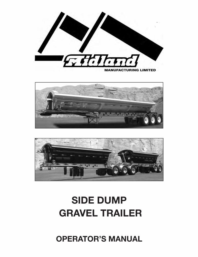
SIDE DUMP GRAVEL TRAILER
OPERATOR’S MANUAL

SIDE DUMP TRAILER
Warranty Registration FormInspection Report
WARRANTY REGISTRATION
This form must be filled out by the dealer and signed by both the dealer and the customer at the time of delivery.
Customer’s Name: Dealer’s Name:
Address: Address:
City: City:
Province/State: Province/State:
Postal/Zip Code: Postal/Zip Code:
Phone Number: ( )
Email:
Trailer Model:
Serial Number:
Delivery Date:
DEALER INSPECTION REPORT SAFETY
Landing Gear Moves Freely and Crank Stowed Safety Signs / Decals Installed Air Lines Properly Stowed (No Air Leaks) Manual Supplied Electrical Lines Stowed All Reflectors Installed and Clean Tires at Specified Pressure All Lights Functioning Wheels Properly Torqued Brakes Release at Proper Pressure Brakes Adjusted Check Integrity of All Frame & Hoist Pins
I have thoroughly instructed the buyer on the above described equipment which review included the
Operator’s Manual content, equipment care, adjustments, safe operation and applicable warranty policy.
Date: Dealer’s Rep. Signature:
The above equipment and Operator’s Manual has been received by me and I have been thoroughly
instructed and understood as to care, adjustments, safe operation and applicable warranty policy.
Date: Owner’s Signature:
WHITE
MIDLAND
YELLOW
DEALER
PINK
CUSTOMER
Box 249Rosenort, MBR0G 1W0CANADA
FOREWORD
The following instructions provide a general description of the proper procedures which must be considered before starting operations with any of Midland Manufacturing Limited's dump equipment.
Although the information in this manual was current on the date of issue, Midland Manufacturing Limited reserves the right to effect changes as the need occurs without notice or liability.


MIDLAND MANUFACTURING LIMITED TRAILER WARRANTY
Midland Manufacturing Limited (hereafter referred to as “Midland”) warrants directly to you, the first retail customer; that each new trailer manufactured by Midland is free from defects in material and workmanship; provided that the trailer is being properly maintained; and that the trailer is being used in it’s normal intended service free from accident or collision.
Normal service means usage in the manner and for the purpose for which such trailer is generally manufactured, purchased and utilized; including the loading, unloading, and carriage of uniformly distributed legal loads of non corrosive cargo, in a manner which does not subject this vehicle to strains, impacts, and dump cycles greater than normally imposed by lawful use over properly maintained public roads, with gross vehicle weight, gross axle weights and concentrated loads not exceeding the labeled gross vehicle weight, gross axle weight and concentrated load ratings (also see "Usage Qualifier" note below).
The warranty shall (unless otherwise specified) be for the following period following the date of delivery:
- Structural components (manufactured by Midland) – five years (conditional / prorated)*- Non-structural components (manufactured by Midland) – one year- Midland does not warrant parts and accessories supplied by others. Midland assigns to the
customer any warranties provided in favor of Midland with respect to any such parts and accessories; which may be legally assigned by Midland.
* Prorated / Conditional warranty of components manufactured by Midland:
- Structural components1st & 2nd year - 100% of repair.3rd year - 75% of repair.4th year - 50% of repair.5th year - 25% of repair.
- Non-structural componentsOne year - 100% parts and labor.
- Usage (years) Qualifier: Midland's warranty may be modified; at Midland's discretion, if said trailer(s) is subjected to exceptionally heavy use; i.e.: Trailer(s) running 24 hours/day, 7 days a week, or some similar scenario. Thus, for example, for every year in use; the trailer(s) is considered to be two (2) or more "usage" years old.
Midland’s warranty will not cover any repairs done without prior discussion;quotation; and express written approval by Midland
Midland’s warranty coverage does not include:
- freight (of parts, components, or the trailer)- downtime (loss of income)- other incidental or consequential damages

Midland warranty does not cover:
- Parts that are not defective but which may wear out and have to be replaced; including but not limited to seals, lights, paint, suspension components, brake system components, brake linings, brake drums, bushings (suspension, joints, hinges, and knuckles), tires, wood pieces and the like.
- Alignments or adjustments which are normal maintenance items; not caused by a defect in any components or in the trailer.
- Any trailer or component of a trailer that has been altered (other than by Midland) in any way so as in the judgement of Midland; to affect its operation or reliability, or which has been subject to misuse, neglect or accident.
Warranty claims:
ON ANY REPAIRS UNDER WARRANTY, MIDLAND MUST BE CONTACTED AND OUR APPROVAL RECEIVED IN THE FORM OF A WARRANTY PURCHASE ORDER BEFORE ANY WORK IS DONE.
THE PURCHASER CLAIMING UNDER THIS WARRANTY SHALL SUBMIT A WARRANTY CLAIM IN THE PRESCRIBED FORM TO MIDLAND OR AN AUTHORIZED DEALER FOR INSPECTION BY AN AUTHORIZED COMPANY REPRESENTATIVE.
1) We will not accept warranty bills / invoices under any circumstances that have not received our prior authorization (including a warranty authorization number); based on a written quotation for the required repair work.
2) We are to supply all warranty parts unless agreed otherwise.
3) Any invoices covering warranty parts and / or labor that we consider excessive will be paid on the basis of our cost of such parts and / or labor as if the work had been done at our factory.
4) No warranty on parts will be paid for until the faulty parts have been returned prepaid, for our inspection, unless agreed otherwise.Midland will not be responsible for freight for returned parts except by prior arrangement and written authorization.
5) All invoices submitted, requesting warranty, must show the number of hours of labor and the rate being charged.
6) Midland must receive notice of a defect immediately after such defect is discovered and at the request of Midland or an authorized agent return the trailer to Midland or an authorized agent or other agreed upon location within 20 days after the trailer return is requested. Note: Warranty consideration may be influenced by "when a defect ought to have been discovered under normal circumstances"; in cases where the defect notification is not made in a timely manner.
7) Transportation expenses to and from a repair facility are the responsibility of the trailer owner.
WARRANTY DISCLAIMER AND LIMITATIONS OF LIABILITY:
Except for the above warranty, Midland makes no other express warranties and HEREBY EXCLUDES ANY IMPLIED WARRANTY OF MERCHANTABILITY OR FITNESS FOR PARTICULAR PURPOSE.
IT IS AGREED THAT MIDLAND SHALL NOT BE LIABLE FOR INCIDENTAL OR CONSEQUENTIAL DAMAGES RESULTING FROM ANY BREACH OF WARRANTY including, but not limited to, loss of income, damage to vehicle, attachments, trucks or cargo, towing expenses, or injury to or death of persons.
No person is authorized to give any warranties or to assume any other liability on Midland’s behalf unless
made and assumed in writing by Midland and signed by an officer of Midland.TIME LIMIT ON COMMENCING LEGAL ACTION:
While Midland undertakes to make reasonable efforts to resolve every warranty claim, if Midland does not accept as valid all or any part of a particular claim, then Midland will only be responsible under this warranty for such claim if it is enforced by legal action commenced within one year from the date that the breach of warranty occurred.
WARRANTY TRANSFER:
Warranty transfers to a second owner will be recognized provided:
- the said transfer takes place in the first twelve (12) months of service- the said trailer is fully inspected and approved by Midland by way of a personal inspection by
an authorized Midland agent- a new warranty form is filled out and sent to Midland Manufacturing Limited immediately upon
close of the transaction. (New Equipment Warranty forms are available from Midland). - the second warranty form must be returned to Midland showing name of original purchaser
and date the trailer was put into service as well as the date and name of the new owner. Any and all warranty periods are begun on the date of sale of the new trailer to the original retail customer.
OPERATORS MANUAL:
The purchaser acknowledges having received training in the safe operation of the trailer unit and further acknowledges that Midland does not assume any liability resulting from the operation of the trailer unit in any manner other than described in the operator’s manual supplied at the time of purchase.
THIS AGREEMENT IS NOT VALID UNLESS A SIGNED COPY OF THE WARRANTY REGISTRATION FORM IS RECEIVED BY MIDLAND WITH 15 DAYS OF DATE OF DELIVERY; TO THE FIRST RETAIL CUSTOMER.
Midland Manufacturing LimitedBox 249
Rosenort, Manitoba, Canada R0G 1W0

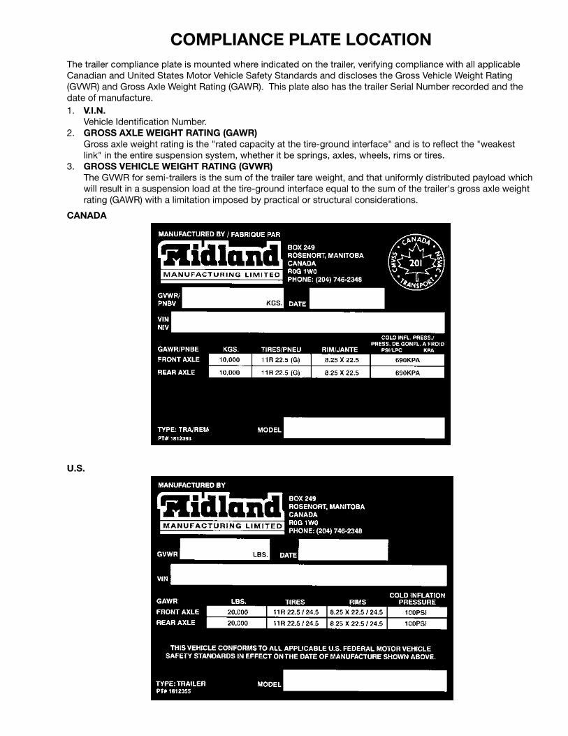
COMPLIANCE PLATE LOCATIONThe trailer compliance plate is mounted where indicated on the trailer, verifying compliance with all applicable Canadian and United States Motor Vehicle Safety Standards and discloses the Gross Vehicle Weight Rating (GVWR) and Gross Axle Weight Rating (GAWR). This plate also has the trailer Serial Number recorded and the date of manufacture.1. V.I.N. Vehicle Identification Number.2. GROSS AXLE WEIGHT RATING (GAWR) Gross axle weight rating is the "rated capacity at the tire-ground interface" and is to reflect the "weakest
link" in the entire suspension system, whether it be springs, axles, wheels, rims or tires.3. GROSS VEHICLE WEIGHT RATING (GVWR) The GVWR for semi-trailers is the sum of the trailer tare weight, and that uniformly distributed payload which
will result in a suspension load at the tire-ground interface equal to the sum of the trailer's gross axle weight rating (GAWR) with a limitation imposed by practical or structural considerations.
U.S.
CANADA

V.I.N. PLATE LOCATIONAlways give your dealer the V.I.N. (Vehicle Identification Number) of your Midland End Dump Trailer unit when ordering parts or requesting service or other information.
The plate is located where indicated. Please mark the number in the space provided for easy reference. Also obtain and mark down the Model Number, Production Year and other pertinent information of your Trailer unit in the spaces provided.
SERIAL NUMBER LOCATION
V.I.N. Number
Model Number
Length
Suspension
Axles
Wheels
Tires
Date Purchased
Dealer Purchased From
Address

TABLE OF CONTENTS
SECTION DESCRIPTION PAGE
1 Introduction ............................................................1 2 Safety .......................................................................2 2.1 General Safety ..........................................................3 2.2 Operating Safety .......................................................4 2.3 Maintenance Safety ..................................................4 2.4 Hydraulic Safety .......................................................5 2.5 Travel Safety .............................................................5 2.6 Loading Safety ..........................................................5 2.7 Tire Safety .................................................................6 2.8 Safety Signs/Decals .................................................6 2.9 Sign-Off Form ...........................................................7 3 Safety Sign (Decal) Locations ................................8 4 Operation Guidelines ............................................10 4.1 To the New Operator or Owner ...............................10 4.2 Terminology ............................................................11 4.3 Break-In ..................................................................12 4.4 Controls ..................................................................14 4.5 Pre-Operation Vehicle Inspection Procedure .........18 4.6 Hooking Up/Unhooking ..........................................21 4.6.1 Hooking Up .............................................................21 4.6.2 Unhooking ..............................................................23 4.7 Loading/Unloading .................................................24 4.8 Transporting ............................................................27 4.8.1 Operating Instructions ............................................27 4.8.2 Braking Guidelines..................................................28 4.8.3 Tires ........................................................................29 5 Service and Maintenance ....................................30 5.1 Service ....................................................................30 5.1.1 Fluids and Lubricants .............................................30 5.1.2 Greasing .................................................................30 5.1.3 Servicing Intervals ..................................................31 5.1.4 Servicing Record Summary (Lubrication) ...............44
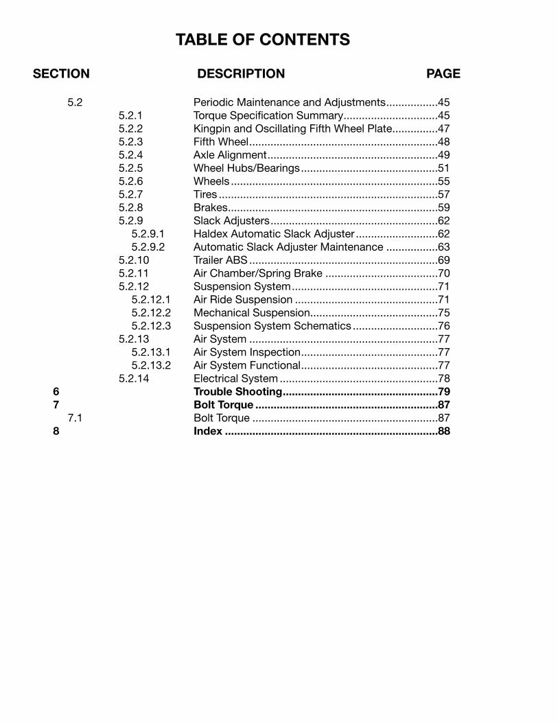
TABLE OF CONTENTS
SECTION DESCRIPTION PAGE
5.2 Periodic Maintenance and Adjustments .................45 5.2.1 Torque Specification Summary ...............................45 5.2.2 Kingpin and Oscillating Fifth Wheel Plate ...............47 5.2.3 Fifth Wheel ..............................................................48 5.2.4 Axle Alignment ........................................................49 5.2.5 Wheel Hubs/Bearings .............................................51 5.2.6 Wheels ....................................................................55 5.2.7 Tires ........................................................................57 5.2.8 Brakes .....................................................................59 5.2.9 Slack Adjusters .......................................................62 5.2.9.1 Haldex Automatic Slack Adjuster ...........................62 5.2.9.2 Automatic Slack Adjuster Maintenance .................63 5.2.10 Trailer ABS ..............................................................69 5.2.11 Air Chamber/Spring Brake .....................................70 5.2.12 Suspension System ................................................71 5.2.12.1 Air Ride Suspension ...............................................71 5.2.12.2 Mechanical Suspension..........................................75 5.2.12.3 Suspension System Schematics ............................76 5.2.13 Air System ..............................................................77 5.2.13.1 Air System Inspection .............................................77 5.2.13.2 Air System Functional .............................................77 5.2.14 Electrical System ....................................................78 6 Trouble Shooting ...................................................79 7 Bolt Torque ............................................................87 7.1 Bolt Torque .............................................................87 8 Index ......................................................................88

1 INTRODUCTIONMidland Manufacturing appreciates having you for our customer and trust this unit will give you many years of trouble-free use. We are pleased to have you join a growing number of operators pulling Midland trailers.
We take pride in building products to meet the demands of a discriminating buyer in the transportation industry. We have sought to anticipate your needs with respect to safety, convenience, design and engineering of your unit. Midland Manufacturing provides information and service support to its customers through its distributor and dealer network. Contact the dealer or Midland should you need assistance.
Safe, efficient and trouble free operation of your Midland Trailer requires that you and anyone else who will be operating or maintaining the Trailer, read this manual carefully and understand the Safety, Operation, Maintenance and Trouble Shooting information contained within the Operator's Manual. Failure to read and follow the instructions in the manual could lead to costly repairs; and even more importantly could lead to serious injury and possibly death.
1
This manual covers all the Side Dump Gravel Trailer models built by Midland.
Although some of the diagrams and pictures may not apply to all trailers, we have tried to show details of common adjustments and features that are on standard production units.
Use the Table of Contents or Index as a guide in locating the specific information applicable to your Trailer. Keep this manual handy for frequent reference and to pass on to new operators or owners.
OPERATOR ORIENTATION - The directions left and right as mentioned throughout this manual, are taken as if the operator was standing behind the trailer facing forward.

3 Big Reasons
SIGNAL WORDS:
This Safety Alert symbol means ATTENTION! BECOME ALERT! YOUR SAFETY IS INVOLVED!
2 SAFETY
SAFETY ALERT SYMBOL
2
The Safety Alert symbol identifies important safety messages on the Midland Trailer and in the manual. When you see this symbol, be alert to the possibility of personal injury or death. Follow the instructions in the safety message.
Why is SAFETY important to you?
Note the use of the signal words DANGER,WARNING and CAUTION with the safety messages. The appropriate signal word for each message has been selected using thefollowing guide-lines:
Indicates an imminently hazardous situation that, if not avoided, will result in death or serious injury. This signal word is to be limited to the most extreme situations, typically for machine components that, for functional purposes, cannot be guarded.
Indicates a potentially hazardous situation that, if not avoided, could result in death or serious injury, and includes hazards that are exposed when guards are removed. It may also be used to alert against unsafe practices.
Indicates a potentially hazardous situation that, if not avoided, may result in minor or moderate injury. It may also be used to alert against unsafe practices.
WARNING:
CAUTION:
Accidents Disable and Kill Accidents Cost Accidents Can Be Avoided
DANGER:

3
2.1 GENERAL SAFETY
1. Read and understand the Operators Manual and all safety signs before operating, maintaining or adjusting the Trailer.
2. Only trained competent persons shall operate the Trailer. An untrained operator is not qualified to operate the unit.
3. Have a first-aid kit available for use should the need arise and know how to use it.
4. Do not allow riders.
5. Have a fire extinguisher available for use should the need arise and know how to use it.
6. Wear appropriate protective gear. This list includes but is not limited to:
- A hard hat - Protective
shoes with slip resistant soles
- Heavy gloves
7. Place all controls in neutral, stop truck engine, set park brake, remove ignition key and wait for all moving parts to stop and all air pressure to be fully exhausted before servicing, adjusting or repairing.
8. Do not drink and drive.
SAFETY
YOU are responsible for the SAFE operation and maintenance of your Midland Trailer. YOU MUST ensure that you and anyone else who is going to operate, maintain or work around the Trailer be familiar with all the operating and maintenance procedures and related SAFETY information contained in this manual.
Remember, YOU are the key to safety. Good safety practices not only protect you but also the people around you. Make these practices a working part of your safety program. Be certain that EVERYONE operating this equipment is familiar with the recommended procedures and follows all the safety precautions. Remember, accidents can be prevented. Do not risk injury or death.
• Remember, you are not just a driver; you are expected to be an effective and efficient operator. Drivers may only drive but an operator is a very safe, cost efficient and professional person.
• Trailer owners MUST give operating instructions to operators or employees before allowing them to operate the equipment, and at least annually thereafter.
• The most important safety device on this equipment is a SAFE operator. It is the operator’s responsibility to read and understand ALL Safety and Operating instructions in the manual and to follow these. "All" accidents can be avoided.
• Midland feels that a person who has not read, understood and been trained to follow all operating and safety instructions is not qualified to operate the equipment. An untrained operator exposes himself and bystanders to possible serious injury or death.
• DO NOT modify the equipment in any way. Modification may impair the function and/or safety of the equipment and affect Trailer life.
• Think SAFETY! Work SAFELY!

4
2.2 OPERATING SAFETY
1. Read and understand all of the Operator’s Manual and all safety signs before operating or adjusting the Midland Trailer.
2. Do not allow riders on any part of the trailer during either field operation or road and highway travel.
3. Drive very carefully when negotiating hilly or uneven terrain.
4. Keep hands, feet, clothing and hair away from all moving parts.
5. Place all controls in neutral, stop the truck engine, remove ignition key, set the park brake before adjusting, servicing or maintaining any part of the Trailer unit.
6. Stay away from side of trailer when truck engine is running. Keep others away.
7. Use care when dumping load. Always know where your operating partner is before moving tub to prevent injury.
8. Stay away from the side of tub when dumping load. Large objects in load or load itself can hit personnel. Keep others away.
9. Maintain king pin, fifth wheel assembly and all
running gear in good condition at all times.
10. Clear the area of all bystanders, especially children, before starting up and operating the tractor and trailer.
11. Make sure that all lights and reflectors that are required by the local highways and transport authorities are in place, clean and can be seen clearly by all overtaking and oncoming traffic.
12. Do not operate unit with spring brakes caged or brakes disabled. Block wheels if unhooked.
13. Before disconnecting the tractor from the trailer unit(s) make sure that the tractor and trailer are on level ground and that the trailer wheels are securely blocked. Lower landing gear and provide extra support if the ground is soft. Do not unhook if trailer is loaded.
14. Do not dump unless the trailer is on firm level surface.
15. Review safety items with all personnel annually.
2.3 MAINTENANCE SAFETY
1. Read and understand all the information in the Operator’s Manual regarding maintenance, adjusting and servicing the Trailer unit.
2. Place all controls in neutral, stop the truck engine, remove ignition key, set the park brake before adjusting, servicing or maintaining any part of the Trailer unit.
3. Follow good shop practices: - Keep service area
clean and dry. - Be sure electrical
outlets and tools are properly grounded.
- Use adequate light for the job at hand.
4. Cage spring brake chamber before disassembling.
5. Block wheels before de-activating brakes.
6. Disconnect air lines and exhaust air system before working on discharge gates.
7. Maintain fasteners in running gear systems at their specified torque at all times.
8. Establish and maintain a Trailer Preventative Maintenance (TPM) program on your equipment. Some jurisdictions require this program and the maintenance of records on every commercial vehicle on the road for future reference.

5
2.4 HYDRAULIC SAFETY
1. Make sure that all components in the hydraulic system are kept in good condition and are clean.
2. Replace any worn, cut, abraded, flattened or crimped hoses or lines.
3. Relieve hydraulic pressure completely before working on hydraulic system.
4. Do not attempt any makeshift repairs to the hydraulic fittings or hoses by using tape, clamps or cements. The hydraulic system operates under extremely high-pressure. Such repairs will fail suddenly and create a hazardous and unsafe condition.
5. Wear proper hand and eye protection when searching for a high-pressure hydraulic leak. Use a piece of wood or cardboard as a backstop instead of hands to isolate and identify a leak.
6. If injured by a concentrated high-pressure stream of hydraulic fluid, seek medical attention immediately. Serious infection or toxic reaction can develop from hydraulic fluid piercing the skin surface.
7. Before applying pressure to the system, make sure all components are tight and that lines, hoses and couplings are not damaged.
2.5 TRAVEL SAFETY
1. Read and understand all the information in the operator’s manual regarding procedures and safety when operating the Trailer unit in the field or on the road.
2. Make sure all the lights and reflectors that are required by the local highway and transport authorities are in place, are clean and can be seen clearly by all overtaking and oncoming traffic.
3. Drive carefully and defensively at all times and especially when negotiating uneven or hilly terrain.
4. Do not allow riders on any part of the trailer.
5. Make sure you are in compliance with all local regulations regarding transporting on public roads and highways. Consult your local law enforcement agency for further details.
2.6 LOADING SAFETY
1. Do not drop load on trailer to prevent damaging sides or bottom.
2. Use common sense when loading material containing large rocks or frozen chunks to prevent damaging tub.
3. Do not exceed total carrying specifications for trailer.
6
2.7 TIRE SAFETY
1. Failure to follow proper procedures when mounting a tire on a wheel or rim can produce an explosion which may result in serious injury or death.
2. Do not attempt to mount a tire unless you have the proper equipment and experience to do the job.
3. Have a qualified tire dealer or repair service perform required tire maintenance.
2.8 SAFETY SIGNS
1. Keep safety signs clean and legible at all times.
2. Replace safety signs that are missing or have become illegible.
3. Replaced parts that displayed a safety sign should also display the current sign.
4. Safety signs are available from your Distributor or the factory.
How to Install Safety Signs/Decals:
• Be sure that the installation area is clean and dry.
• Be sure temperature at the area of contact is above 50°F (10°C).
• Decide on the exact position before you remove the backing paper.
• Remove the smallest portion of the split backing paper.
• Align the sign over the specified area and carefully press the small portion with the exposed sticky backing in place.
• Slowly peel back the remaining paper and carefully smooth the remaining portion of the sign in place.
• Small air pockets can be pierced with a pin and smoothed out using the piece of sign backing paper.
DATE EMPLOYEE'S SIGNATURE EMPLOYER'S SIGNATURE
SIGN-OFF FORM
2.9 SIGN-OFF FORM
Midland Manufacturing follows the general Safety Standards specified by the Society of Automotive Engineers (SAE) and the Occupational Safety and Health Administration (OSHA). Anyone who will be operating and/or maintaining the Midland Trailer must read and clearly understand ALL Safety, Operating and Maintenance information presented in this manual.
Do not operate or allow anyone else to operate this equipment until such information has been reviewed and understood. Annually review this information with all personnel.
Make these periodic reviews of SAFETY and OPERATION a standard practice for all of your equipment.
A sign-off sheet is provided for your record keeping to show that all personnel who will be working with the equipment have read and understand the information in the Operator’s Manual and have been instructed in the operation of the equipment.
7
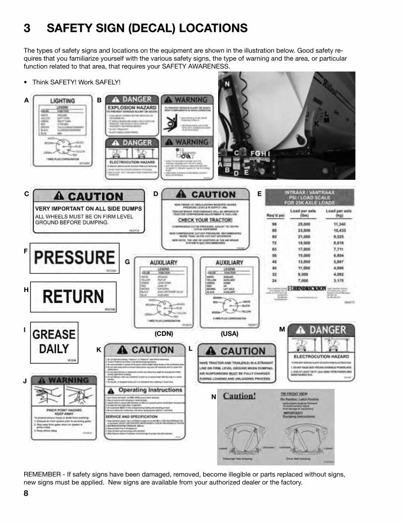
3 SAFETY SIGN (DECAL) LOCATIONS
The types of safety signs and locations on the equipment are shown in the illustration below. Good safety re-quires that you familiarize yourself with the various safety signs, the type of warning and the area, or particular function related to that area, that requires your SAFETY AWARENESS.
• Think SAFETY! Work SAFELY!
8
REMEMBER - If safety signs have been damaged, removed, become illegible or parts replaced without signs, new signs must be applied. New signs are available from your authorized dealer or the factory.
A
J
I
H
F
EDC
B
L
M
N
K
(USA)(CDN)
G
9
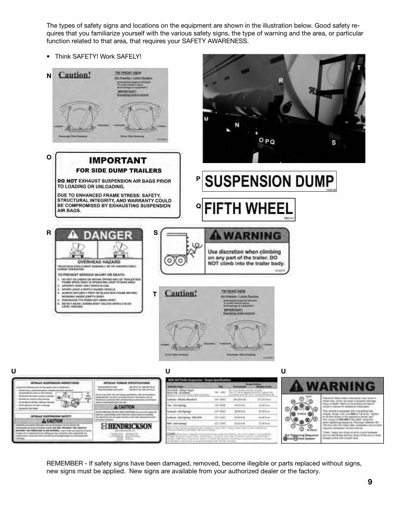
The types of safety signs and locations on the equipment are shown in the illustration below. Good safety re-quires that you familiarize yourself with the various safety signs, the type of warning and the area, or particular function related to that area, that requires your SAFETY AWARENESS.
• Think SAFETY! Work SAFELY!
REMEMBER - If safety signs have been damaged, removed, become illegible or parts replaced without signs, new signs must be applied. New signs are available from your authorized dealer or the factory.
T
SR
Q
P
O
N
U U U
10
4 OPERATION GUIDELINES
OPERATING SAFETY
4.1 TO THE NEW OPERATOR OR OWNER
The Midland Side Dump Gravel Trailers combine light weight construction methods and high strength materials to become a safe, reliable and efficient material hauling unit. Be sure to familiarize yourself with the Trailer by reading and understanding this Operator's Manual and the Safety Alerts before attempting to operate it. With careful use and a good maintenance schedule, the unit will give many years of trouble-free use.
It is the responsibility of the owner and operator to be familiar with the weight and loading of your trailer or combinations of trailers. Trailer weight and loading vary from jurisdiction to jurisdiction. Be familiar with yours and any that you will be travelling through.
1. Read and understand all the Operator’s Manual and all safety signs before operating or adjusting the Midland Trailer.
2. Do not allow riders on any part of the trailer during either field operation or road and highway travel.
3. Drive very carefully when negotiating hilly or uneven terrain.
4. Keep hands, feet, clothing and hair away from all moving parts.
5. Place all controls in neutral, stop the truck engine, set park brake, remove ignition key and wait for all moving parts to stop and all air pressure be fully exhausted before servicing, adjusting, repairing or maintaining.
6. Stay away from side of trailer when truck engine is running. Keep others away.
7. Use care when dumping load. Always know where your operating partner is before moving trailer body to prevent injury.
8. Stay away from the side of trailer body when dumping load. Large objects in load or load itself can hit personnel. Keep others away.
9. Maintain king pin, fifth wheel assembly and all running gear in good condition at all times.
10. Clear the area of all bystanders, especially children, before starting up and operating the tractor and trailer.
11. Make sure that all lights and reflectors that are required by the local highways and transport authorities are in place, clean and can be seen clearly by all overtaking and oncoming traffic.
12. Do not operate unit with spring brakes caged or brakes disabled. Block wheels if unhooked.
13. Before disconnecting the tractor from the trailer unit(s) make sure that the tractor and trailer are on level ground and that the trailer wheels are securely blocked. Lower landing gear and provide extra support if the ground is soft. Do not unhook if trailer is loaded.
14. Do not dump unless vehicle is on firm level surface.
15. Review safety items with all personnel annually.

4.2 TERMINOLOGY
The Midland Side Dump Trailers are designed with hydraulic cylinders at the front and rear of the tub to lift and tilt for unloading. Each side of the tub is equipped with 2 latches/pivots to release/anchor the unit during unloading. They are available in dual or tri-axle models and single trailer or B-Train designs. Some of the standard models and typical features are shown.
11
Fig. 1 PRINCIPLE SYSTEMS
A Tri-Axle TrailerB Tandem-Axle
TrailerC Trailer BodyD Front CylinderE Rear CylinderF Latch/PivotG Push Block
4.2 TERMINOLOGY
The Midland Side Dump Trailers are designed with hydraulic cylinders at the front and rear of the tub to lift and tilt for unloading. Each side of the tub is equipped with 2 latches/pivots to release/anchor the unit during unloading. They are available in dual or tri-axle models and single trailer or B-Train designs. Some of the standard models and typical features are shown.
11Fig. 1 PRINCIPLE SYSTEMS
A Tri-Axle TrailerB Tandem-Axle
TrailerC Trailer BodyD Front CylinderE Rear CylinderF Latch/PivotG Push Block

12
4.3 BREAK-IN
Break-in is the most important time in a Trailer's life. It is critical that the unit be checked frequently during the first 5000 miles to be sure that all components and systems are properly adjusted and performing as required.
The following inspection schedule is provided as a guide for normal operating conditions. More frequent inspections are recommended in severe or extreme conditions.
Inspect at:50-100 miles, 1-2 hours500 miles, 8-10 hours1500 miles, 25-30 hours5000 miles, 100 hours: 1. Brakes It takes a few weeks of operation for the brake
shoes to mate with the drum contour and burnish the surface. During this period of time, the operator should check the brakes every day. After the first month, inspection of the brakes before each trip or every 10,000 miles is required. Check the function and adjustment of the brakes on each axle. All brakes should apply evenly. No shoes should drag on the drum when the brakes are not applied.
2. Tires Tires are designed to provide maximum life and
performance when maintained at their specified inflation pressure. Although the tires are inflated to their specified pressure at the factory, the pressure can change and should be checked before going into service. Always use an accurate gauge to check the pressure when the tire is cold.
3. Wheels/Rims Although lug bolts and rim fasteners are always
tightened to their specified torque at the factory, it is normal for them to lose some of their torque during the first few miles of operation. Always retorque lug bolts and rim fasteners to be sure that they stay tight. Then go to the retorquing interval defined in the Maintenance section of every 25,000 miles or more often if necessary. Keep all fasteners tightened to their specified torque to prevent damaging any components.
Whenever a wheel is removed from an axle, the above retorquing procedure must be followed to be sure that the wheel is secured to the axle. If any component is damaged due to loose fasteners, it will have to be replaced.
4. Axles Each wheel bearing is assembled at the factory
with the required pre-load (refer to Section 5.2.4). This pre-load should be checked to insure proper axle and bearing function. Check the temperature of the hub by hand after 10 to 15 miles (15 to 25 km) during the first trip. A hot hub must have the bearing pre-load reset before continuing.
Jack the axle up and support it on a stand. Turn the wheel by hand. The wheel should turn freely. If it does not, check if the brakes are dragging or if the bearing has too much pre-load. If either of these conditions exist, correct before proceeding.
Move the wheel laterally on the axle shaft. If the wheel wobbles, the bearing has lost its pre-load. Tighten bearing and set pre-load before continuing.
5. Hub Oil Levels: Oil bath hubs are used on all trailers and are filled
at the factory. Check hubs frequently (at least daily) during the first few weeks of operation. Always check when the oil is cold and the trailer is on the level. Use the level mark on the hub face when checking oil level. Replace seals and gaskets if hub has an oil leak. Do not operate without oil in the hub.

4.3 BREAK-IN (cont'd)
6. Suspension A suspension system connects the axles to the
frame. All fasteners must be maintained at their specified torque to ensure that all clamping and anchoring forces remain intact. If these forces are not maintained, components can shift or move and affect the performance and component life. Refer to Maintenance Section for the list of required torque values for all fasteners in suspension system. Any loosening can lead to component shifting, misalignment and/or twisting. Any of these items can cause erratic handling, broken components or rapid tire wear. Always tighten the nut end of fastener. Specified torque values apply only to nut end torquing.
7. Axle Alignment Axle alignment is properly set at the factory
when the unit is new and will remain aligned unless fasteners loosen or components wear. Use a steel measuring tape to check the alignment. Refer to Maintenance Section for alignment checking procedure. Axles that are out of alignment can cause erratic handling characteristics, broken components and accelerated tire wear.
8. Fifth Wheel Assembly Components The king pin, upper and lower fifth wheel
assemblies must be inspected to check for mechanical integrity of all components. All components and systems must be kept in good condition to safely and reliably transmit the accelerating, braking and side loads between the trailer, fifth wheel and towing vehicle.
a. King Pin: Check the king pin for cracks, chips, or
whether it is bent. Check that there are no cracks or distortions between the king pin and its anchor plate before resuming work.
b. Fifth Wheel Assembley: The fifth wheel assembly consists of the king
pin locking mechanism, surface plate, frame, pivot and anchor system. Check that the king pin locking mechanism locks and unlocks easily and that all moving surfaces are coated with grease. Check that the surface plate is clean and coated with grease.
Check the surface plate, pivot and anchor frame for cracks, bends or distortions. Replace any damaged components. Retorque fasteners to maintain the proper clamping forces on all components to move or bend and create mechanical or safety problems during operation.
9. Electrical and Air Lines Electrical and air lines extend from the front of the
unit to each light and air operated component. Although they are all anchored along their routing pathways from the factory, they occasionally do come loose and will sag. Inspect all electrical and air lines. Use plastic ties to secure line to frame if any are loose and sag. Replace if any are pinched, kinked, cut or abraded. Extra care should be taken in cold or extreme operating conditions. Ice, mud or brush can pull lines loose from their anchors and cause damage. Clean components, repair damage, re-anchor and install protectors if appropriate. Do not operate with damaged components.
13
Hydraulic valve with air-shift control TW3500
14
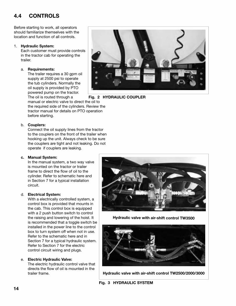
4.4 CONTROLS
Before starting to work, all operators should familiarize themselves with the location and function of all controls.
1. Hydraulic System: Each customer must provide controls
in the tractor cab for operating the trailer.
a. Requirements: The trailer requires a 30 gpm oil
supply at 2500 psi to operate the tub cylinders. Normally the oil supply is provided by PTO powered pump on the tractor. The oil is routed through a manual or electric valve to direct the oil to the required side of the cylinders. Review the tractor manual for details on PTO operation before starting.
b. Couplers: Connect the oil supply lines from the tractor
to the couplers on the front of the trailer when hooking up the unit. Always check to be sure the couplers are tight and not leaking. Do not operate if couplers are leaking.
c. Manual System: In the manual system, a two way valve
is mounted on the tractor or trailer frame to direct the flow of oil to the cylinder. Refer to schematic here and in Section 7 for a typical installation circuit.
d. Electrical System: With a electrically controlled system, a
control box is provided that mounts in the cab. This control box is equipped with a 2 push button switch to control the raising and lowering of the hoist. It is recommended that a toggle switch be installed in the power line to the control box to turn system off when not in use. Refer to the schematic here and in Section 7 for a typical hydraulic system. Refer to Section 7 for the electric control circuit wiring and plugs.
e. Electric Hydraulic Valve: The electric hydraulic control valve that
directs the flow of oil is mounted in the trailer frame.
Fig. 2 HYDRAULIC COUPLER
Fig. 3 HYDRAULIC SYSTEM
Hydraulic valve with air-shift control TW2500/2000/3000
15
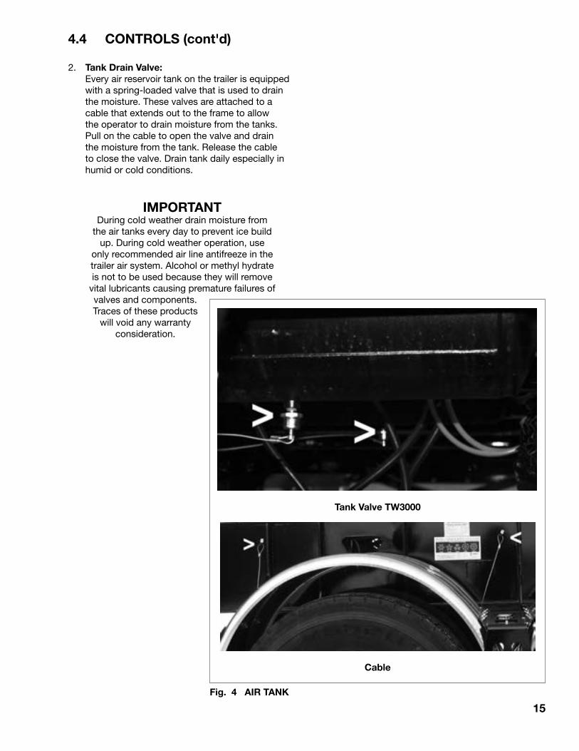
4.4 CONTROLS (cont'd)
2. Tank Drain Valve: Every air reservoir tank on the trailer is equipped
with a spring-loaded valve that is used to drain the moisture. These valves are attached to a cable that extends out to the frame to allow the operator to drain moisture from the tanks. Pull on the cable to open the valve and drain the moisture from the tank. Release the cable to close the valve. Drain tank daily especially in humid or cold conditions.
IMPORTANTDuring cold weather drain moisture from
the air tanks every day to prevent ice build up. During cold weather operation, use
only recommended air line antifreeze in the trailer air system. Alcohol or methyl hydrate is not to be used because they will remove
vital lubricants causing premature failures of valves and components. Traces of these products
will void any warranty consideration.
Fig. 4 AIR TANK
Cable
Tank Valve TW3000

16
4.4 CONTROLS (cont'd)
3. Latches/Pivots: Each side of the frame is
designed with 2 latches/pivots to control the motion of the tub when unloading. Each anchor has a pinned latch that holds or releases the pivot.
Fig. 5 LATCHES/PIVOTS
Latched
Location
17
4.4 CONTROLS (cont'd)
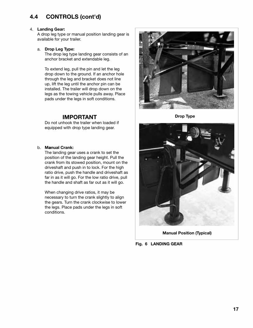
4. Landing Gear: A drop leg type or manual position landing gear is
available for your trailer.
a. Drop Leg Type: The drop leg type landing gear consists of an
anchor bracket and extendable leg.
To extend leg, pull the pin and let the leg drop down to the ground. If an anchor hole through the leg and bracket does not line up, lift the leg until the anchor pin can be installed. The trailer will drop down on the legs as the towing vehicle pulls away. Place pads under the legs in soft conditions.
IMPORTANT Do not unhook the trailer when loaded if
equipped with drop type landing gear.
b. Manual Crank: The landing gear uses a crank to set the
position of the landing gear height. Pull the crank from its stowed position, mount on the driveshaft and push in to lock. For the high ratio drive, push the handle and driveshaft as far in as it will go. For the low ratio drive, pull the handle and shaft as far out as it will go.
When changing drive ratios, it may be necessary to turn the crank slightly to align the gears. Turn the crank clockwise to lower the legs. Place pads under the legs in soft conditions.
Fig. 6 LANDING GEAR
Manual Position (Typical)
Drop Type

18
4.5 PRE-OPERATION VEHICLE INSPECTION PROCEDURE
The safe and trouble-free use of a Midland Trailer requires the operator to maintain the unit in good operating condition. To assist the operator, a pre-operation checklist is provided that should be followed each time before the trailer is used.
NOTEThe tractor items, part of the Department of Transport (D.O.T.) walk around sequence, have been omitted.
WALK AROUND SEQUENCE
Step 1 - Trailer Frontal Area
1. Air and Electrical Connections a. Glad hands properly mounted, free of
damage, not leaking and not worn.
b. Electrical line receptacle properly mounted, free of damage, plug adequately seated and safety catch engaged to prevent accidental disconnection.
c. Hydraulic couplers properly seated and tightened, no leaks and properly secured against tangling, snagging and chafing, with sufficient slack for turning.
d. Air, electrical and hydraulic lines properly secured to avoid tangling, snagging and chafing with sufficient slack for turns.
2. Lights and Reflectors a. Front trailer clearance and identification lights
- should be clean, operating and proper color.
b. Reflectors and conspicuousy tape clean and proper color.
3. Hydraulic Cylinder a. Free to move on pivot.
b. No oil leaks.
Step 2 - Coupling System Area
1. Fifth Wheel (Lower) a. Securely mounted to frame.
b. No missing or damaged parts.
c. No visible space between upper and lower fifth wheel.
d. Locking jaws around the shank and not the head of Kingpin.
e. Release lever properly seated and safety latch lock engaged.
Fig. 7 WALKAROUND SEQUENCE

19
4.5 PRE-OPERATION (cont'd)
2. Fifth Wheel (Upper) a. Kingpin not worn, bent or damaged.
b. Anchor frame not cracked, bent, worn or damaged.
3. Air, Hydraylic and Electric Lines Visible From This Point a. Should be secure from dangling, snagging
and chafing.
b. Should be free from damage and clean.
Step 3 - Right of Trailer Area
1. Front Trailer Support (Landing Gear) a. Fully raised and secured, no missing parts,
not bent or otherwise damaged.
b. Crank handle present and secured (typically on left side).
2. Spare Tires a. Carrier or rack not damaged.
b. Tire and/or wheel securely mounted in the rack.
c. Tire and wheel condition adequate. Proper spare tire size, correctly inflated.
3. Lights and Reflectors a. Trailer side clearance lights clean, operating
and proper colour.
b. Reflectors and conspicuously tape clean and proper colour.
4. Frame and Body a. Frame and cross members not bent, cracked,
damaged or missing.
b. Body parts not damaged or missing.
5. Air Tank a. Drain moisture from air tank(s) daily. Pull on
cable attached to drain valve. Hold cable until the tank moisture is drained and the stream is clear.
NOTE During cold weather drain moisture from
the air tanks every day to prevent ice build up. During cold weather operation, use only recommended air line anti freeze in the trailer air system. Alcohol or methyl hydrate is not to be used because they will remove vital lubricants causing premature
failures of valves and components. Traces of these products will void any warranty consideration.
Step 4 - Right Rear Trailer Wheel Area
1. Dual Wheels a. Condition of wheels and rims, no cracked or
bent rims, broken spacers, studs, clamps or lugs.
b. Condition of tires - properly inflated, valve stems not touching wheel rims or brake drums, valve caps in place, no serious cuts, bulges, tread wear or any signs of misalignment and no debris stuck between the tires.
c. Tires all same type e.g. do not mix radial and
bias types on the same axles.
d. Wheel bearings and hub - no obvious leaking.
e. Mud flaps in place and in good condition.
2. Tandem or Triaxles a. Repeat wheel and tire inspection as above.
b. Flexible air lines not cracked, cut, crimped or otherwise damaged, secured against tangling, dragging or chafing.
3. Suspension a. Mechanical: Condition of spring(s), spring
hangers, equalizers and U-bolts.
b. Air: Condition of air bag(s), axle clamping bolts, pivot arm and height control valve.
c. Axle alignment.
d. Retorque all fasteners.
Step 5 - Brakes
1. Brakes a. Condition of brake drum(s).
b. Condition of hoses, lines and valves.
c. Check slack adjusters.
d. Check air chamber mounting.
e. Check spring brakes (if so equipped).
f. Drain moisture from air tank with cable.

20
4.5 PRE-OPERATION (cont'd)
Step 6 - Right of Trailer Area
1. Lights and Reflectors a. Rear clearance and identification lights, clean
and operating and proper colour.
b. Reflectors and conspicuously tape clean and proper colour.
2. Hydraulic Cylinder a. Free to move on pivot.
b. No oil leaks.
3. Check "B" train 5th wheel: Repeat same as Step 2 "Coupling System Area".
Step 7 - Left Rear Trailer Wheel Area
Check all items as done on right side (Step 4 "Right Rear Trailer Wheel Area").
Step 8 - Left Side of Trailer Area
Check all items as done on right side (Step 3 "Right Side of Trailer Area").
Step 9 - Trailer(s) Functional Check (Tractor Attatched)
1. Check for proper connection of the air brake glad-hands, hydraulic system couplers and secure contact of electrical connection.
2. Start engine.
3. Build up air pressure in the tractor-trailer systems.
4. Turn on lights and inspect for proper function of: a. Clearance lights. b. Identification lights. c. Turn signals and 4-way flasher. d. Sidemarker lights. e. Tail lights. f. Stop lights.
5. Check the function of brakes. a. Apply service brakes. b. Apply parking brakes. c. Apply emergency brakes. d. Stop engine. i. Release trailer emergency brakes. ii. Apply service brakes.
Air loss should not exceed 3 psi per minute on single vehicles. 4 psi per minute on combination.
Fig. 8 WALKAROUND SEQUENCE
Step10 - On Trailer Transporting Hazardous Material
1. Check marking and placards.
2. Check for proper shipping papers.
21
4.6 HOOKING UP/UNHOOKING
Special care should be taken when hooking up or unhooking trailer to be sure the equipment is in good condition and all systems are functioning as required.
4.6.1 HOOKING UP
Follow this procedure when hooking up the trailer to towing vehicle (tractor or lead trailer):
1. Back the towing vehicle up in a straight line to the trailer and align the fifth wheel opening with the trailer king pin.
2. Stop before the fifth wheel makes contact with the trailer and apply the towing vehicle parking brake.
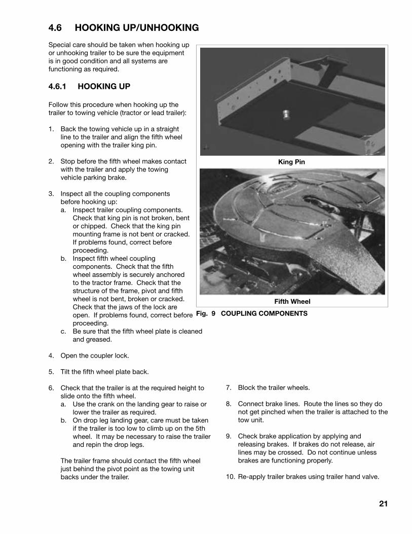
3. Inspect all the coupling components before hooking up:
a. Inspect trailer coupling components. Check that king pin is not broken, bent or chipped. Check that the king pin mounting frame is not bent or cracked. If problems found, correct before proceeding.
b. Inspect fifth wheel coupling components. Check that the fifth wheel assembly is securely anchored to the tractor frame. Check that the structure of the frame, pivot and fifth wheel is not bent, broken or cracked. Check that the jaws of the lock are open. If problems found, correct before proceeding.
c. Be sure that the fifth wheel plate is cleaned and greased.
4. Open the coupler lock.
5. Tilt the fifth wheel plate back.
6. Check that the trailer is at the required height to slide onto the fifth wheel.
a. Use the crank on the landing gear to raise or lower the trailer as required.
b. On drop leg landing gear, care must be taken if the trailer is too low to climb up on the 5th wheel. It may be necessary to raise the trailer and repin the drop legs.
The trailer frame should contact the fifth wheel
just behind the pivot point as the towing unit backs under the trailer.
King Pin
Fifth Wheel
Fig. 9 COUPLING COMPONENTS
7. Block the trailer wheels.
8. Connect brake lines. Route the lines so they do not get pinched when the trailer is attached to the tow unit.
9. Check brake application by applying and releasing brakes. If brakes do not release, air lines may be crossed. Do not continue unless brakes are functioning properly.
10. Re-apply trailer brakes using trailer hand valve.

22
5th Wheel
Lock
Fig. 10 COUPLER LOCKS
4.6.1 HOOKING UP (cont'd)
11. Back slowly under trailer keeping the king pin centered in the fifth wheel jaws.
12. Back up until the fifth wheel coupler locks on the trailer king pin.
13. Gently move the towing vehicle back and forth while the trailer brakes are engaged to check that the jaws have locked around the king pin.
14. Set parking brake, stop engine and dismount.
15. Visually check that the coupler jaws are securely locked around the king pin and the coupler release lever is in the locked position. Release and hook up again if the jaws are not securely locked around the king pin.
16. Check that the trailer front frame is resting on the fifth wheel.
17. Connect and secure the hydraulic line. Start hydraulic pump and check that there are no leaks.
18. Connect and secure the electrical terminal. Check that all electrical circuits are completed and that all lights are working.
19. Route the electrical, air and hydraulic lines to prevent snagging, dragging and pinching.
20. Raise the landing gear. a. Remove the anchor pins, raise leg and repin
on the drop leg style. b. Use the crank to raise the legs if equipped
with the crank style. Stow crank.
21. Remove blocks or chocks from the wheels.
22. Perform Pre-Trip Inspection before starting.
4.6.2 UNHOOKING
1. Position towing unit and trailer in a straight line on a clear, level and firm surface.
2. Apply the trailer brakes and the parking brakes on the tractor before dismounting.
3. Place blocks or chocks in front of and behind trailer wheels if not on a level surface.
4. Place large blocks or planks under landing gear if the ground is soft.
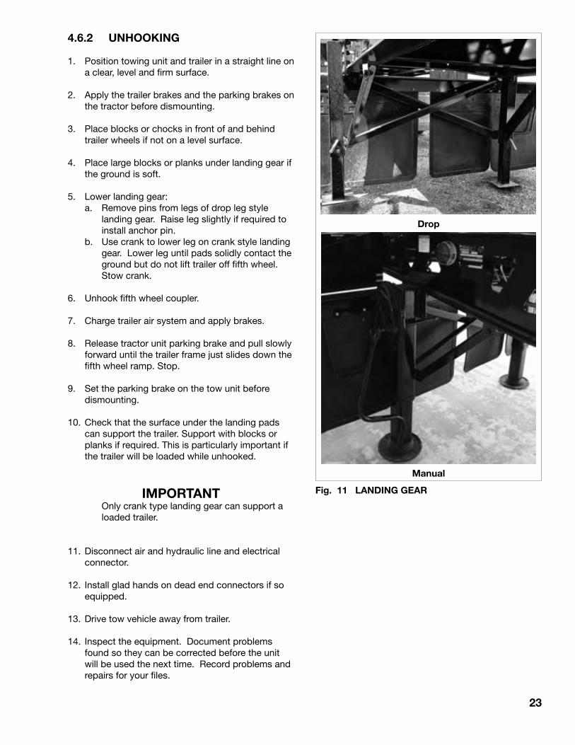
5. Lower landing gear: a. Remove pins from legs of drop leg style
landing gear. Raise leg slightly if required to install anchor pin.
b. Use crank to lower leg on crank style landing gear. Lower leg until pads solidly contact the ground but do not lift trailer off fifth wheel. Stow crank.
6. Unhook fifth wheel coupler.
7. Charge trailer air system and apply brakes.
8. Release tractor unit parking brake and pull slowly forward until the trailer frame just slides down the fifth wheel ramp. Stop.
9. Set the parking brake on the tow unit before dismounting.
10. Check that the surface under the landing pads can support the trailer. Support with blocks or planks if required. This is particularly important if the trailer will be loaded while unhooked.
IMPORTANT Only crank type landing gear can support a
loaded trailer.
11. Disconnect air and hydraulic line and electrical connector.
12. Install glad hands on dead end connectors if so equipped.
13. Drive tow vehicle away from trailer.
14. Inspect the equipment. Document problems found so they can be corrected before the unit will be used the next time. Record problems and repairs for your files.
23
Fig. 11 LANDING GEAR
Manual
Drop
24
4.7 LOADING/UNLOADING
It is the responsibility of the operator to review and be familiar with the trailer loading capacity specifications and be sure that you comply with any and all load limitations or restrictions applicable in the jurisdictions where you will be travelling. Exceeding the trailer weight specifications can result in damage to the structure and voids the manufacturer's warranty. Exceeding the road restrictions is illegal.
Loading/unloading procedures and instructions are covered but not limited to those summarized below:
A. Loading 1. Clear the area of bystanders
and remove debris from loading area.
2. Position the trailer as required and set park brake before dismounting.
3. Be sure the tub is fully down resting on the latching/pivot points.
4. Minimize the drop height when loading.
a. Position the loading equipment as close to the bottom of the trailer as possible.
b. Do not load trailer unless hooked to towing unit.
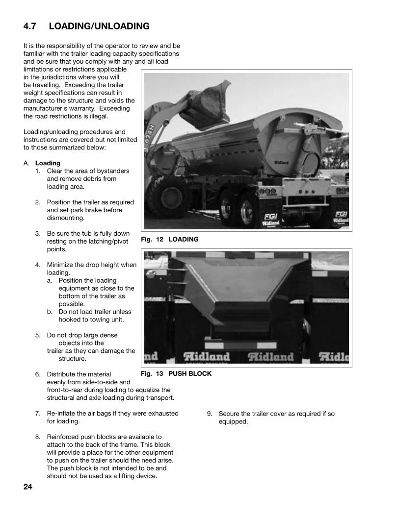
5. Do not drop large dense objects into the
trailer as they can damage the structure.
6. Distribute the material evenly from side-to-side and front-to-rear during loading to equalize the structural and axle loading during transport.
7. Re-inflate the air bags if they were exhausted for loading.
8. Reinforced push blocks are available to attach to the back of the frame. This block will provide a place for the other equipment to push on the trailer should the need arise. The push block is not intended to be and should not be used as a lifting device.
Fig. 12 LOADING
Fig. 13 PUSH BLOCK
9. Secure the trailer cover as required if so equipped.

25
4.7 LOADING/UNLOADING (cont'd)
B. Unloading 1. Clear the area of bystanders and
remove debris from unloading area.
2. Determine the unloading side. Latch the pivot side and release lifting side.
3. Open and remove the tarp if so equipped.
4. Proceed to the unloading area.
5. Stop when in position for unloading.
Fig. 14 ANCHORS
Latched
6. When unloading a TW train configuration, always unload the pup prior to unloading the lead.
26
4.7 LOADING/UNLOADING (cont'd)
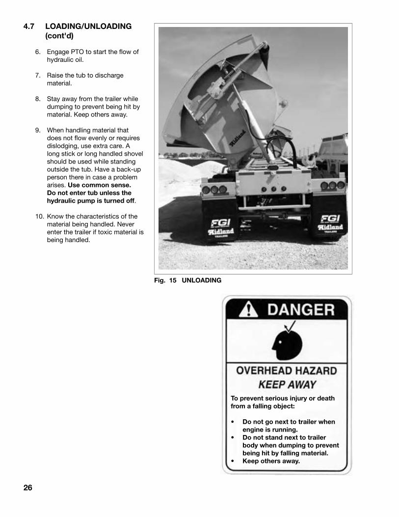
6. Engage PTO to start the flow of hydraulic oil.
7. Raise the tub to discharge material.
8. Stay away from the trailer while dumping to prevent being hit by material. Keep others away.
9. When handling material that does not flow evenly or requires dislodging, use extra care. A long stick or long handled shovel should be used while standing outside the tub. Have a back-up person there in case a problem arises. Use common sense. Do not enter tub unless the hydraulic pump is turned off.
10. Know the characteristics of the material being handled. Never enter the trailer if toxic material is being handled.
Fig. 15 UNLOADING
To prevent serious injury or death from a falling object:
• Do not go next to trailer when engine is running.
• Do not stand next to trailer body when dumping to prevent being hit by falling material.
• Keep others away.

27
4.8 TRANSPORTING
By following the previous instructions, your Midland trailer unit has been hooked-up and is ready to go. Although all operating instructions are common sense, it is wise to review them periodically to refresh your memory. Good operational procedures result in a safe workplace for the operator and others.
4.8.1 OPERATING INSTRUCTIONS
Since this equipment can be used in a variety of conditions, it is difficult to give instructions appropriate for all applications. However, these general guidelines apply to all situations:
1. Be sure that the trailer is securely attached to the towing vehicle and locked into position.
2. Be sure that the air and hydraulic lines are securely connected and that they have sufficient slack for turns.
3. Ensure that the brakes are properly adjusted and in good working condition.
4. Ensure that the electrical harness is securely attached and all lights and reflectors are clean
and operating.
5. Maintain the mud flaps in good condition to minimize road splash in wet conditions.
6. Always maintain the trailer in good mechanical condition.

28
4.8.2 BRAKING GUIDELINES
Safe, reliable and trouble-free operation of your trailer requires that the brakes be maintained in good operating condition at all times and the driver follows good application techniques when driving. The irresponsible use of brakes by the driver when travelling can contribute to low brake life or result in system malfunctions, short tire life and poor tire wear patterns. The following list summarizes some basic operational guidelines for the driver.
1. Check the function of the brake system before starting a trip.
2. Maintain a safe vehicle speed at all times. Slow down for rough road or slippery surface conditions, winding roads or congested areas.
3. Always provide sufficient vehicle spacing on the road to allow for a safe stopping distance.
4. Apply brakes gradually to produce an even deceleration until the vehicle is stopped.
5. Watch traffic patterns ahead. Anticipate pattern changes that could result in an emergency. Apply the brakes gradually in sufficient time to produce a controlled stop.
6. Shift to a lower gear to use engine compression as the retarding force when going down steep grades.
7. Do not apply brakes for a long period of time such as when travelling on a long downgrade. The brakes will overheat. Instead, apply both the tractor and trailer brakes for short periods of time giving the brakes a chance to cool between applications.
8. Dry the brakes by applying them several times after going through water.
9. Release the brakes just before going over railroad tracks or other rough conditions. By allowing the wheels to turn over rough road surfaces, there will be no shock loads to the brake system components or produce flat spots on the tires.
10. Wet, icy or snow-packed surfaces require special care. Make cautious, intermittent applications by fanning or pumping the brakes to reduce speed without skidding or locking the wheels.
11. Use caution when applying the tractor driveline brake should you lose the service brake system. Rapid and hard application of the driveline brake can result in axle or driveline component failures with the resulting loss of all braking systems.
12. Use wheel chocks, apply trailer and tractor parking brakes and place tractor in low gear when parking the unit.
13. Maximum brake retarding occurs just before the wheels lock up and the tires skid. Release the brakes should you feel them lock-up and reapply them.
14. When trailer brakes are applied with hot drums, it may result in a cracked drum. Allow them to cool before reapplying the brakes.
15. Fanning or repeated on-and-off applications will use up the system air reserves. This procedure is not recommended unless adverse road conditions are encountered. The wasting of air reserves in this way could result in insufficient application pressure should an emergency arise.
16. Hard or panic stops can overheat the linings and drums. Overheating will cause brake fade. Severe overheating and fade can result in the complete loss of braking capability. This will substantially reduce the expected life of brakes.

29
4.8.3 TIRES
When operating the trailer, it is the responsibility of the driver to check the tires frequently. Inflation pressures, wear patterns and matching are critical parameters that must be monitored. The following factors affect tire care:
1. Inspection frequency: Tires should always be checked before the start of a run and twice during the day or every 4 operating hours, whichever comes first. It is also a good practice to check the tires at each rest period during the day. When a driver hears unusual noise or experiences unusual handling characteristics, the first item to check is the tires. Problems found early, during frequent tire checks, can save more serious problems later on. A sampling of typical abnormal wear patterns are shown in the Maintenance section along with their causes. Always correct the cause of the tire wear problem before proceeding.
2. Inflation pressure: Tires should always be operated at their specified pressures. At their specified pressures, the tire is designed to run with the full width of the tread flat on the contact surface. Operating at other than specified pressures will change the tread
contact patterns and can dramatically shorten tire life. In addition, the tires will run hotter and can lead to blow-outs.
Check tire pressure when the tire is cold. A hot tire can read as much as 20 psi higher than a cold tire. If tires are over-inflated, check for poor load distribution, uneven surface contact, over-loading or poor operating conditions.
3. Tire matching: Do not mix ply types on the same axle. Their operating characteristics are different and will lead to uneven tire loading, rapid tire wear and adverse handling characteristics. Matching also includes combining tires that have the same amount of tread remaining. A tire with more tread has a larger rolling radius and will have to carry a higher load. The best performance will be obtained when the rolling radius is within 1/8" for all tires on an axle.

30
5 SERVICE AND MAINTENANCEThis section provides information on daily and periodic service and maintenance of the Trailer unit. Follow these recommendations for safe and dependable operation of the Trailer unit. Refer to the safety section at the front of the operator's manual for all applicable safe maintenance and operating procedures.
Be sure that all operators are familiar with the operation and maintenance procedures and related safety information contained in the operator's manual.
5.1 SERVICE
5.1.1 FLUIDS AND LUBRICANTS
1. Grease: Use an SAE multi-purpose lithium based grease
with extreme pressure (EP) characteristics.
2. Wheel Hub Oil: a. Use an SAE 80W90 for normal temperature
conditions (-10°F to 100°F ambients).
b. Use an SAE 85W140 for hot temperature conditions (100°F and hotter ambients).
c. Use an SAE 30W motor oil for ambients below -10°F.
Capacity: 1 pint (500 ml)
3. Hydraulic Oil: Use an SAE 10W or 20-20W viscosity standard
industrial hydraulic oil for all operating conditions.
Cylinder Capacity: 265 - 230 litres, 60 U.S. gal 250 & smaller - 200 litres, 50 U.S. gal. 4. Storing Lubricants Your Trailer can operate at top efficiency only if
clean lubricants are used. Use clean containers to handle all lubricants. Store them in an area protected from dust, moisture and other contaminants.
MAINTENANCE SAFETY
1. Read and understand all the information in the Operator’s Manual regarding maintenance, adjusting and servicing the Trailer unit.
2. Place all controls in neutral, lower box or block box, stop the engine, remove ignition key and set the park brake before adjusting, servicing or maintaining any part of the Trailer unit.
3. Follow good shop practices: - Keep service area clean and dry. - Be sure electrical outlets and tools are
properly grounded. - Use adequate light for the job at hand.
4. Cage spring brake chamber before disassembling.
5. Block wheels before de-activating brakes.
6. Disconnect air lines and exhaust air system before working on end gate.
7. Maintain fasteners in running gear systems at their specified torque at all times.
8. Establish and maintain a Trailer Preventative Maintenance (TPM) program on your equipment. Some jurisdictions require this program and the maintenance of records on every commercial vehicle on the road for future reference.
5.1.2 GREASING
Refer to Section 5.1.1 for recommended grease. Use the Service Record checklist provided tokeep a record of all scheduled servicing.
1. It is recommended that a high-pressure air greaser be used for greasing to insure that the bushings receive sufficient lubricant.
2. Wipe grease fitting with a clean cloth before greasing, to avoid injecting dirt and grit.
3. Replace and repair broken fittings immediately.
4. If fittings will not take grease, remove and clean thoroughly. Also clean lubricant passageway. Replace fitting if necessary.

31
5.1.3 SERVICING INTERVALS
A standard servicing schedule is provided as a guide for your convenience. In unusual or extreme operating conditions, increase the frequency or perform additional service items to customize this schedule to your application.
Daily, 10 hours or 500 Miles
1. Grease the top and bottom hydraulic cylinder bushings on the front and rear (2 locations each cylinder).
Fig. 16 CYLINDER BUSHINGS
Rear
Front

32
5.1.3 SERVICING INTERVALS (cont'd)
2. Drain moisture from air tanks (use cables to open drain valves).
IMPORTANT During cold weather drain
moisture from the air tanks every day to prevent ice build up. During cold weather operation, use only recommended air line anti freeze in the trailer air system. Alcohol or methyl hydrate is not to be used because they will remove vital lubricants causing premature failures of valves and components. Traces of these products will void any warranty consideration.
Fig. 17 AIR TANK
Drain Cable
Valve (TW3000)
33
5.1.3 SERVICING INTERVALS (cont'd)
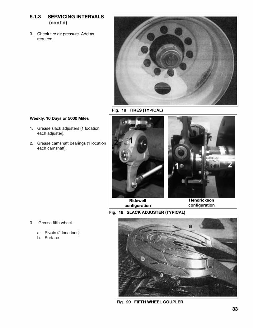
3. Check tire air pressure. Add as required.
Weekly, 10 Days or 5000 Miles
1. Grease slack adjusters (1 location each adjuster).
2. Grease camshaft bearings (1 location each camshaft).
3. Grease fifth wheel.
a. Pivots (2 locations). b. Surface
Fig. 18 TIRES (TYPICAL)
Fig. 20 FIFTH WHEEL COUPLER
Fig. 19 SLACK ADJUSTER (TYPICAL)
Hendricksonconfiguration
Ridewellconfiguration

34
5.1.3 SERVICING INTERVALS (cont'd)
4. Check wheel hub oil levels.
5. Retorque the following fasteners:
a. Brake/wheel end system fasteners. Refer to Section 5.2.7.
Schematic
Hub
Fig. 21 HUB OIL LEVEL
Manual Bearing Adjustmenta. Tighten to 100 ft-lbs. c. Tighten to 50 ft-lbs.b. Completelt loosen. d. Loosen 1/4 turn.
Fig. 22 BRAKE/WHEEL END
35
5.1.3 SERVICING INTERVALS (cont'd)
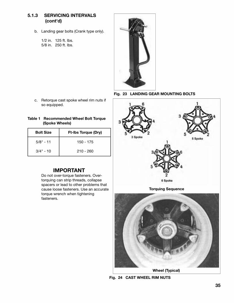
b. Landing gear bolts (Crank type only).
1/2 in. 125 ft. lbs. 5/8 in. 250 ft. lbs.
c. Retorque cast spoke wheel rim nuts if so equipped.
Table 1 Recommended Wheel Bolt Torque (Spoke Wheels)
IMPORTANT Do not over-torque fasteners. Over-
torquing can strip threads, collapse spacers or lead to other problems that cause loose fasteners. Use an accurate torque wrench when tightening fasteners.
Wheel (Typical)
Fig. 24 CAST WHEEL RIM NUTS
Torquing Sequence
Fig. 23 LANDING GEAR MOUNTING BOLTS
Bolt Size Ft-lbs Torque (Dry)
5/8" - 11
3/4" - 10
150 - 175
210 - 260
36
5.1.3 SERVICING INTERVALS (cont'd)
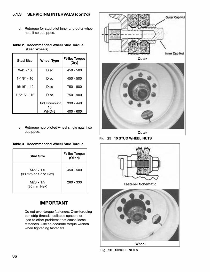
d. Retorque for stud pilot inner and outer wheel nuts if so equipped.
Table 2 Recommended Wheel Stud Torque (Disc Wheels)
e. Retorque hub piloted wheel single nuts if so equipped.
Table 3 Recommended Wheel Stud Torque
IMPORTANT
Do not over-torque fasteners. Over-torquing can strip threads, collapse spacers or lead to other problems that cause loose fasteners. Use an accurate torque wrench when tightening fasteners.
Fig. 25 10 STUD WHEEL NUTS
Outer
Outer
Wheel
Fastener Schematic
Fig. 26 SINGLE NUTS
Stud SizeFt-lbs Torque
(Dry)
3/4" - 16
1-1/8" - 16
15/16" - 12
1-5/16" - 12
Wheel Type
Disc
Disc
Disc
Disc
Bud Unimount10
WHD-8
450 - 500
450 - 500
750 - 900
750 - 900
390 - 440
400 - 600
Ft-lbs Torque (Oiled)Stud Size
M22 x 1.5(33 mm or 1-1/2 Hex)
M20 x 1.5(30 mm Hex)
450 - 500
280 - 330
37
5.1.3 SERVICING INTERVALS (cont'd)
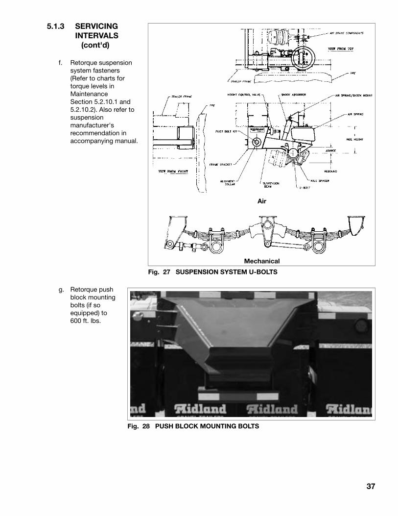
f. Retorque suspension system fasteners (Refer to charts for torque levels in Maintenance Section 5.2.10.1 and 5.2.10.2). Also refer to suspension manufacturer's recommendation in accompanying manual.
g. Retorque push block mounting bolts (if so equipped) to 600 ft. lbs.
Air
Fig. 27 SUSPENSION SYSTEM U-BOLTS
Mechanical
Fig. 28 PUSH BLOCK MOUNTING BOLTS

38
5.1.3 SERVICING INTERVALS (cont'd)
10,000 Miles (15,000 kms) or Monthly
1. Grease landing gear bearings (3 locations) (crank type only).
Fig. 29 LANDING GEAR (TYPICAL)
39
5.1.3 SERVICING INTERVALS (cont'd)
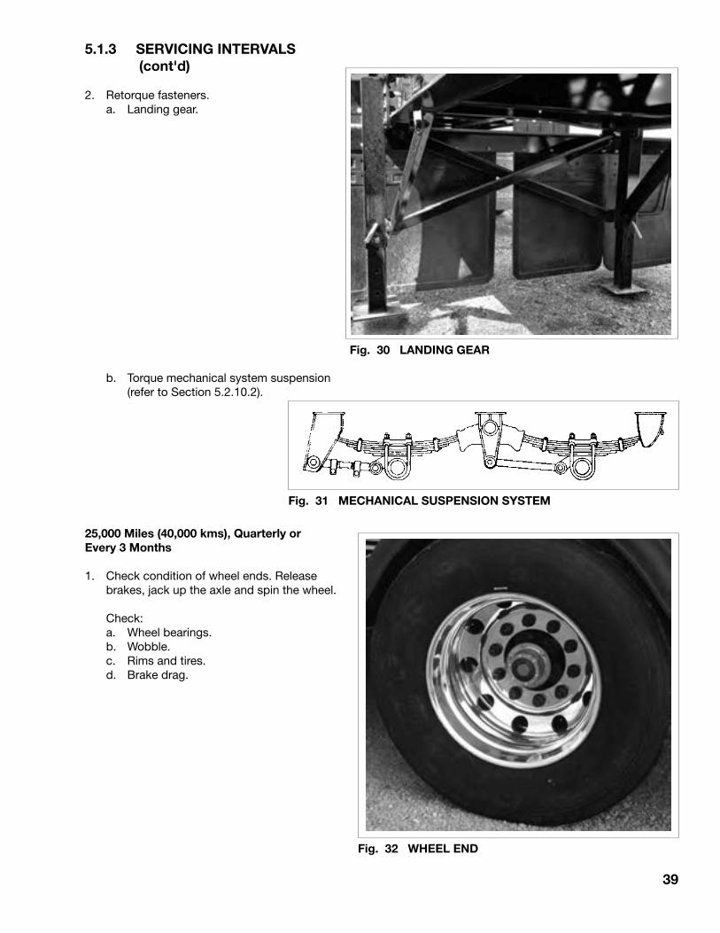
2. Retorque fasteners. a. Landing gear.
25,000 Miles (40,000 kms), Quarterly or Every 3 Months
1. Check condition of wheel ends. Release brakes, jack up the axle and spin the wheel.
Check: a. Wheel bearings. b. Wobble. c. Rims and tires. d. Brake drag.
Fig. 30 LANDING GEAR
Fig. 31 MECHANICAL SUSPENSION SYSTEM
Fig. 32 WHEEL END
b. Torque mechanical system suspension (refer to Section 5.2.10.2).

40
5.1.3 SERVICING INTERVALS (cont'd)
2. Inspect frame and structure for bends, distortion or cracks.
a. Kingpin. b. Fifth wheel and mounts. c. Longitudinal
and transverse frames. d. Latch/Pivot structure. e. Hydraulic cylinder anchor structure. f. Suspension system anchorage. g. Axles. h. Optional accessories. i. Push block.
3. Inspect electrical system components for:
a. Binding. b. Rubbing/abrasion. c. Looseness/dangling. d. Cracks/tears in harness. e. Burned out lights. f. Check that front electrical connector plug anchor female trailer receptacle.
Fig. 33 TRAILER (TW3500 &TW2000)
Fig. 34 ELECTRICAL (TYPICAL)
41
5.1.3 SERVICING INTERVALS (cont'd)
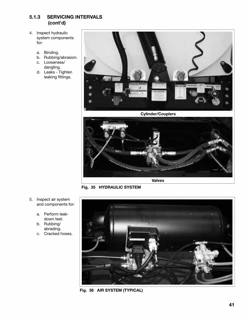
4. Inspect hydraulic system components for:
a. Binding. b. Rubbing/abrasion. c. Looseness/ dangling. d. Leaks - Tighten leaking fittings.
5. Inspect air system and components for:
a. Perform leak- down test. b. Rubbing/ abrading. c. Cracked hoses.
Cylinder/Couplers
Fig. 35 HYDRAULIC SYSTEM
Valves
Fig. 36 AIR SYSTEM (TYPICAL)

42
5.1.3 SERVICING INTERVALS (cont'd)
6. Clean gladhand screens.
7. Check brake lining thickness. Replace as required.
Fig. 37 SCREENS
Fig. 38 BRAKE LINING

43
5.1.3 SERVICING INTERVALS (cont'd)
100,000 Miles (150,000 kms) or Annually
1. Reline brakes as required.
2. Change oil in hubs.
Fig. 39 BRAKE LINING
Fig. 40 HUB OIL (TYPICAL)

44
5.1.4 SERVICING RECORD SUMMARY (LUBRICATION)
LOCATION DESCRIPTION FREQUENCY LUBRICANT
Fifth wheel Coat bearing surface Daily or as needed. Chassi grease.*Coat pivot pins and lock
Landing gear Gearbox and screws. Periodic basis (weekly). Chassi grease.*
Wheels Check oil level. Weekly, 10 Days or 5000 miles (8000 km).
Bearings. 25,000 miles (40,000 km). SAE 80W90 gear oil.
Change oil. 100,000 miles (150,000 km). SAE 80W90 gear oil.
Brakes
Camshaft bearing Lubricate. 5,000 miles (8,000 km) Chassi grease.* or monthly.
Slack Adjuster Lubricate. 5,000 miles (8,000 km) Chassi grease.* or monthly.
Brake shoe anchor Lubricate. 30,000 miles (50,000 km) Chassi grease.*pin bushing or yearly.
Also at brake reline. As appropriate.
* Use good quality lithium based extreme pressure grease throughout. MIL-G25013C in below -40°F.
NOTE: Do not use excessive lubricant.
45
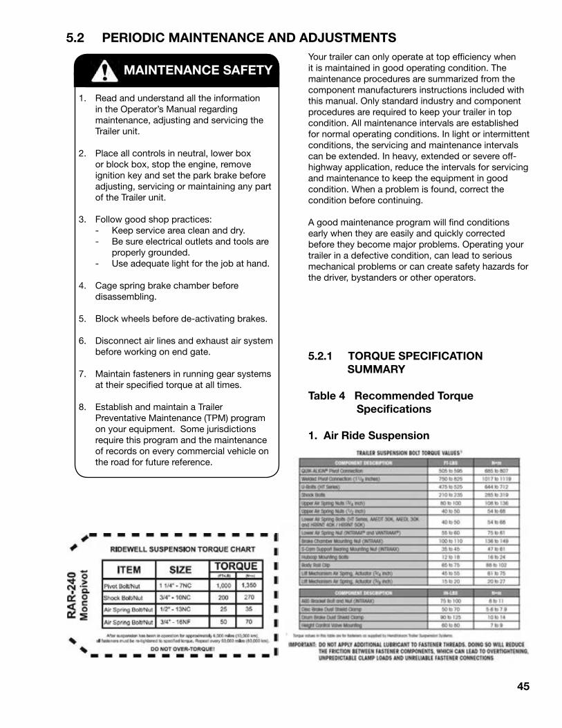
5.2 PERIODIC MAINTENANCE AND ADJUSTMENTS
5.2.1 TORQUE SPECIFICATION SUMMARY
Table 4 Recommended Torque Specifications
1. Air Ride Suspension
Your trailer can only operate at top efficiency when it is maintained in good operating condition. The maintenance procedures are summarized from the component manufacturers instructions included with this manual. Only standard industry and component procedures are required to keep your trailer in top condition. All maintenance intervals are established for normal operating conditions. In light or intermittent conditions, the servicing and maintenance intervals can be extended. In heavy, extended or severe off-highway application, reduce the intervals for servicing and maintenance to keep the equipment in good condition. When a problem is found, correct the condition before continuing.
A good maintenance program will find conditions early when they are easily and quickly corrected before they become major problems. Operating your trailer in a defective condition, can lead to serious mechanical problems or can create safety hazards for the driver, bystanders or other operators.
MAINTENANCE SAFETY
1. Read and understand all the information in the Operator’s Manual regarding maintenance, adjusting and servicing the Trailer unit.
2. Place all controls in neutral, lower box or block box, stop the engine, remove ignition key and set the park brake before adjusting, servicing or maintaining any part of the Trailer unit.
3. Follow good shop practices: - Keep service area clean and dry. - Be sure electrical outlets and tools are
properly grounded. - Use adequate light for the job at hand.
4. Cage spring brake chamber before disassembling.
5. Block wheels before de-activating brakes.
6. Disconnect air lines and exhaust air system before working on end gate.
7. Maintain fasteners in running gear systems at their specified torque at all times.
8. Establish and maintain a Trailer Preventative Maintenance (TPM) program on your equipment. Some jurisdictions require this program and the maintenance of records on every commercial vehicle on the road for future reference.

46
5.2.1 TORQUE SPECIFICATION SUMMARY (cont'd)
Table 4 Recommended Torque Specifications (cont'd)
2. Mechanical Suspension
3. Wheel End Components
Description Fastener SizeTorque Range
(lb-ft) N.m
1. Hub-cap bolts2. Hub fill plug3. Adjustment nut - manual bearing adjustment (double nut)
4. Jam nut - manual bearing adjustment5. Brake mounting bolt6. Two-piece dust shield bolts (shown) * Forged spider7. Bolt-on bushing bolts8. Cam bushing bolts9. Air chamber nuts
10-1515-20
Tighten to 100,loosen, tightento 50, loosen
1/4 turn250-300130-165
15-2025-3525-35
80-125
13-2020-2713668
340-408177-224
20-2734-4834-48
109-170
5/16"3/8"
Size depends on axle model and adjustment
method.
5/8"
3/8"3/8"3/8"5/8"
4. Wheel Nut
Ft-lbs Torque (Dry)Bolt SizeFt-lbs Torque (Dry)
Stud Size Wheel Type
3/4" - 16
1-1/8" - 16
Disc
Disc
Bud Unimount 10WHD-8
450 - 500
450 - 500
390 - 440
400 - 600
5/8" - 11
3/4 ' - 10
150 - 175
210 - 260
47
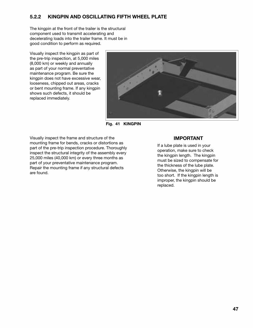
5.2.2 KINGPIN AND OSCILLATING FIFTH WHEEL PLATE
The kingpin at the front of the trailer is the structural component used to transmit accelerating and decelerating loads into the trailer frame. It must be in good condition to perform as required.
Visually inspect the kingpin as part of the pre-trip inspection, at 5,000 miles (8,000 km) or weekly and annually as part of your normal preventative maintenance program. Be sure the kingpin does not have excessive wear, looseness, chipped out areas, cracks or bent mounting frame. If any kingpin shows such defects, it should be replaced immediately.
Visually inspect the frame and structure of the mounting frame for bends, cracks or distortions as part of the pre-trip inspection procedure. Thoroughly inspect the structural integrity of the assembly every 25,000 miles (40,000 km) or every three months as part of your preventative maintenance program. Repair the mounting frame if any structural defects are found.
Fig. 41 KINGPIN
IMPORTANTIf a lube plate is used in your operation, make sure to check the kingpin length. The kingpin must be sized to compensate for the thickness of the lube plate. Otherwise, the kingpin will be too short. If the kingpin length is improper, the kingpin should be replaced.

48
5.2.3 FIFTH WHEEL
A fifth wheel system is used on the rear of the front B train unit and on the towing tractor to secure the kingpin and carry the weight of the attached trailer. It must be maintained in good condition to perform as intended.
Visually inspect the fifth wheel as part of the pre-trip inspection to check for cracks, bends, chips or distortions of the frame and upper plate.
NOTEUse a high-pressure washer or steam cleaner to remove all the grit and grease from the fifth wheel assembly prior to each weekly inspection. Apply a fresh coat of grease to the fifth wheel assembly prior to hooking-up the trailer.
Clean the assembly every 5,000 miles (8,000 km) or weekly and annually to perform a thorough inspection. Check the frame and upper plate for cracks, bends, chips or distortions.
When the components are clean, check that the lock closes completely around the kingpin.
To Adjust the lock:
1. Obtain a Holland kingpin lock tester and place in the throat of the lock. Close the lock.
2. The jaws should be snug around the tester but not binding.
3. Use the adjusting nut on the front edge of the fifth wheel to set the clearance of the jaws.
4. Use a light oil to lubricate all moving parts prior to returning to service.
Fig. 43 KINGPIN LOCK
Fig. 42 FIFTH WHEEL

49
5.2.4 AXLE ALIGNMENT
A standard axle is used as the main transverse structural member to transmit loads between the trailer frame and the surface contacting components. All running gear components are attached to or part of the axle assembly.
Although there is very little that can go wrong with the axle itself, loose, bent or damaged attaching components can cause the axle to go out of alignment. This misalignment will be found during the regularly scheduled 25,000 mile inspection. However, axle misalignment shows itself most commonly by accelerated tire wear and dogtracking by the trailer. Visually check the tire wear when checking air pressure. The driver should identify these handling characteristics to service personnel or correction.
To check axle alignment, follow this procedure:
1. Select a working area that is level, with a compacted surface and is large enough to provide access from all sides.
2. Move the trailer forward and backward several times to remove any binding from the components.
3. Stop the trailer when moving in the forward direction without using trailer brakes. This will give the components a forward bias with no binding.
4. Unhook the trailer and support on the landing gear at the normal highway height and parallel to the ground.
5. Install a commercially available axle extender on each axle or remove the wheels to prevent any components from interfering with the measurements.
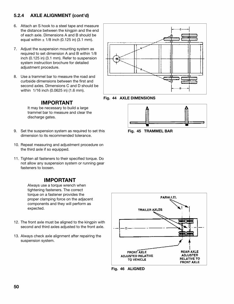
50
Fig. 44 AXLE DIMENSIONS
5.2.4 AXLE ALIGNMENT (cont'd)
6. Attach an S hook to a steel tape and measure the distance between the kingpin and the end of each axle. Dimensions A and B should be equal within ± 1/8 inch (0.125 in) (3.1 mm).
7. Adjust the suspension mounting system as required to set dimension A and B within 1/8 inch (0.125 in) (3.1 mm). Refer to suspension system instruction brochure for detailed adjustment procedure.
8. Use a trammel bar to measure the road and curbside dimensions between the first and second axles. Dimensions C and D should be within 1/16 inch (0.0625 in) (1.6 mm).
IMPORTANTIt may be necessary to build a large trammel bar to measure and clear the discharge gates.
9. Set the suspension system as required to set this dimension to its recommended tolerance.
10. Repeat measuring and adjustment procedure on the third axle if so equipped.
11. Tighten all fasteners to their specified torque. Do not allow any suspension system or running gear fasteners to loosen.
IMPORTANTAlways use a torque wrench when tightening fasteners. The correct torque on a fastener provides the proper clamping force on the adjacent components and they will perform as expected.
12. The front axle must be aligned to the kingpin with second and third axles adjusted to the front axle.
13. Always check axle alignment after repairing the suspension system.
Fig. 45 TRAMMEL BAR
Fig. 46 ALIGNED
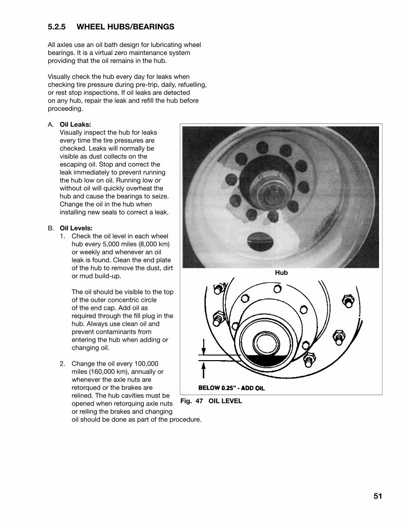
51
5.2.5 WHEEL HUBS/BEARINGS
All axles use an oil bath design for lubricating wheel bearings. It is a virtual zero maintenance system providing that the oil remains in the hub.
Visually check the hub every day for leaks when checking tire pressure during pre-trip, daily, refuelling, or rest stop inspections. If oil leaks are detected on any hub, repair the leak and refill the hub before proceeding.
A. Oil Leaks: Visually inspect the hub for leaks
every time the tire pressures are checked. Leaks will normally be visible as dust collects on the escaping oil. Stop and correct the leak immediately to prevent running the hub low on oil. Running low or without oil will quickly overheat the hub and cause the bearings to seize. Change the oil in the hub when installing new seals to correct a leak.
B. Oil Levels: 1. Check the oil level in each wheel hub every 5,000 miles (8,000 km) or weekly and whenever an oil leak is found. Clean the end plate of the hub to remove the dust, dirt or mud build-up.
The oil should be visible to the top of the outer concentric circle of the end cap. Add oil as required through the fill plug in the hub. Always use clean oil and prevent contaminants from entering the hub when adding or changing oil.
2. Change the oil every 100,000 miles (160,000 km), annually or whenever the axle nuts are retorqued or the brakes are relined. The hub cavities must be opened when retorquing axle nuts or reiling the brakes and changing oil should be done as part of the procedure.
Fig. 47 OIL LEVEL
Hub

52
5.2.5 WHEEL HUBS/BEARINGS (cont'd)
C. Wheel Bearings: Wheel bearings carry and transmit the load
between the wheels and the axles. In addition to proper lubrication, the bearings must have the recommended pre-load to perform as expected. Bearing pre-load is set and controlled by the torque of the wheel nuts on the end of each spindle. Each hub must seat securely on its bearings to prevent wobble or stop in the system. Turning the wheel or wobbling it indicates the condition and tightness of the hub/bearing assembly.
1. Turning/Wobble: a. Park the trailer on a level, hard surface and release the brakes.
b. Place chocks in front of and behind each wheel.
c. Jack each axle up until the tire clears the ground.
d. Support the axle on a safety stand to prevent slipping or tipping.
e. Turning the wheel slowly to check the condition of the bearings and to determine if the brakes are dragging.
f. Dragging Brakes: Can be felt as a steady drag on the turning of the wheel or at the same position or arc or the rotation. Adjust the brakes to eliminate the drag before resuming work.
g. Bearing Condition: Can be felt as the wheel turns. Bearings in good condition turn easily and smoothly. Bearings in poor or bad condition can be felt through the wheels as scraping, grinding, dragging or bumps. Replace bearings before resuming work.
h. Wobble: Grasp each side of the wheel or tire and wiggle the wheel and assembly. If the wheel or hub wobble on the spindle, the bearings have lost their pre-load and the wheel bearing adjusting nut requires tightning.
Fig. 48 WHEELS
NOTEIf the bearings are not in good condition, replace them before setting the pre-load.

53
5.2.5 WHEEL HUBS/BEARINGS (cont'd)
C. Wheel Bearings (cont'd): 2. Bearing Pre-load: a. Place a pan under the hub drain plug. b. Remove the drain plug from the hub and drain the oil. c. Remove the hub end
plate and lay to the side.
d. Remove the set screw from the jam nut.
e. Remove the jam nut and perforated lock washer from the spindle.
f. Use a torque wrench to tighten the adjusting nut 100 ft-lbs. (136 N.m) while rotating the wheel assembly in both directions.
g. Back the adjusting nut off to zero torque.
h. Retorque the adjusting nut again to 50 ft-lbs (68 N.m) of torque while rotating the wheel assembly in both directions.
i. Loosen the nut 1/4 turn.
j. Install the perforated lock washer. Be sure the adjusting nut pin aligns with the hole in the lock washer. Turn washer over and/or adjusting parts as required.
k. Install jam nut and tighten to 250-300 ft-lbs. (340-408 N.m.)
Fig. 49 SPINDLE COMPONENTS
23456789101112131415161718192021
CapscrewLockwasherHub capGasketWheel bearing jam nutLockwasherWheel bearing adjusting nutCone outer wheel bearingCup - bearing outerBrake drumCup - bearing innerCone - bearing innerSeal wheel-bearingBushing anchor pinPin anchorBeam axleCamshaft (left)Camshaft (right)WasherSealBushingSnap ring
DESCRIPTIONITEM1
CapscrewAir chamberLockwasherLocknutCamshaft bushing assemblyCapscrewWasher slack adjusterLocknut - slack adjusterAutomatic slack adjusterWasher slack adjusterSnap ring slack adjusterSpring - brake shoe returnBrake show and lining assy.Spring - brake shoe retainingRetainer - brake shoe rollerRoller - brake shoePin - shoe return springDust shield Hub
2223242526272829303132333435363738394041
DESCRIPTIONITEM
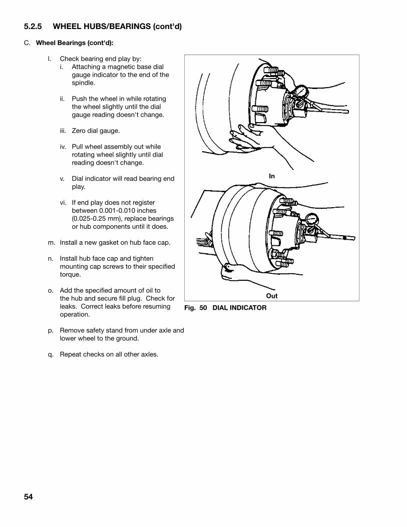
54
5.2.5 WHEEL HUBS/BEARINGS (cont'd)
C. Wheel Bearings (cont'd): l. Check bearing end play by: i. Attaching a magnetic base dial
gauge indicator to the end of the spindle.
ii. Push the wheel in while rotating the wheel slightly until the dial gauge reading doesn't change.
iii. Zero dial gauge.
iv. Pull wheel assembly out while rotating wheel slightly until dial reading doesn't change.
v. Dial indicator will read bearing end play.
vi. If end play does not register between 0.001-0.010 inches (0.025-0.25 mm), replace bearings or hub components until it does.
m. Install a new gasket on hub face cap.
n. Install hub face cap and tighten mounting cap screws to their specified torque.
o. Add the specified amount of oil to the hub and secure fill plug. Check for leaks. Correct leaks before resuming operation.
p. Remove safety stand from under axle and lower wheel to the ground.
q. Repeat checks on all other axles.
In
Out
Fig. 50 DIAL INDICATOR

55
5.2.6 WHEELS
A variety of steel or aluminum wheels can be used on the trailer depending on customer preference or application requirements. Wheels must be maintained in good condition and all fasteners tightened to their specified torque level to obtain the expected life and performance.
Loose fasteners are the most common cause of wheel problems on a trailer. Always retorque the wheel fasteners per the break-in schedule of 100, 500, 1500 and 5,000 miles (160, 800, 2500 and 8000 km) when the unit is new and after a wheel has been removed. Always use an accurate or calibrated torque wrench when tightening fasteners. A loose fastener is defined as one that is not tightened to its specified torque. A loose fastener does not provide the required clamping, anchoring or holding forces to stabilize the adjacent components. Insufficient clamping forces can lead to flexing, bending, cracking, hole elongation or other component deterioration that cause failures and/or accidents. Always keep fasteners tightened to their specified torque. Over-torquing can overload certain components, causing compression cracks and strip nuts or studs. Over-torquing fasteners can be as detrimental as under-torquing. Always tighten fasteners to their specified torque.
Use an accurate torque wrench to retorque wheel fasteners every 10,000 miles (15,000 km) or monthly whichever comes first. Always retorque wheels per the break-in schedule whenever a wheel is removed and remounted.
Always follow the recommended mounting procedure when installing wheels to the trailer.
1. Disc Wheels (Stud Pilot Style): a. Mount single or inner dual wheel on hub. Be
careful not to damage the threads on any of the studs.
b. Snug the nuts up in the alternating sequence shown to center it on the hub and insure an even contact between the wheel and hub.
c. Tighten nuts to their specified torque using the same alternating sequence.
IMPORTANTLeft-hand threads are used on the left side of the vehicle. Right-hand threads on right.
d. Mount outer dual. Do not damage the
threads when sliding the wheel over the studs.
e. Snug up the nuts in the alternating sequence shown to center it on the hub and to provide even contact.
f. Tighten the outer wheel nuts to their specified torque
IMPORTANTWhen retorquing inner nuts of double nut design, always back off outer nut several turns, then retorque them.
Fig. 51 NUT TORQUE SEQUENCE
10 Stud
Table 5 Recommended Wheel Stud Torque (Disc Wheels)
Stud Size
3/4"-16
1-1/8"-16
15/16-12
1-5/16-12
Ft-lbs Torque (Dry)
450 - 500
450 - 500
750 - 900
750 - 900
390 - 440
400 - 600
Wheel Type
Disc
Disc
Disc
Disc
Bud Unimount 10
WHD-8
6 StudSTUD PILOTED
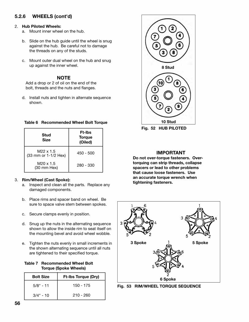
56
8 Stud
5 Spoke3 Spoke
6 Spoke
M22 x 1.5(33 mm or 1-1/2 Hex)
M20 x 1.5(30 mm Hex)
450 - 500
280 - 330
3. Rim/Wheel (Cast Spoke): a. Inspect and clean all the parts. Replace any
damaged components.
b. Place rims and spacer band on wheel. Be sure to space valve stem between spokes.
c. Secure clamps evenly in position. d. Snug up the nuts in the alternating sequence
shown to allow the inside rim to seat itself on the mounting bevel and avoid wheel wobble.
e. Tighten the nuts evenly in small increments in the shown alternating sequence until all nuts are tightened to their specified torque.
Table 7 Recommended Wheel Bolt Torque (Spoke Wheels)
150 - 175
210 - 260
5/8" - 11
3/4" - 10
Table 6 Recommended Wheel Bolt Torque 10 Stud
Fig. 52 HUB PILOTED
5.2.6 WHEELS (cont'd)
2. Hub Piloted Wheels: a. Mount inner wheel on the hub.
b. Slide on the hub guide until the wheel is snug against the hub. Be careful not to damage the threads on any of the studs.
c. Mount outer dual wheel on the hub and snug up against the inner wheel.
NOTEAdd a drop or 2 of oil on the end of the bolt, threads and the nuts and flanges.
d. Install nuts and tighten in alternate sequence
shown.
Stud Size
Ft-lbs Torque (Oiled)
Bolt Size Ft-lbs Torque (Dry)
Fig. 53 RIM/WHEEL TORQUE SEQUENCE
IMPORTANTDo not over-torque fasteners. Over-torquing can strip threads, collapse spacers or lead to other problems that cause loose fasteners. Use an accurate torque wrench when tightening fasteners.

57
5.2.7 TIRES
Tires are one of the most important components on a trailer and must be maintained in top condition to obtain their desired load carrying capacity and durability. Tire wear rate can be used as an indicator of the condition of the axle alignment or suspension system. Poorly maintained tires will wear rapidly or deteriorate and fail quickly and suddenly. A poorly maintained tire can and will affect adjacent components leading to their potential failure as well.
Proper tire maintenance includes but is not limited to:
1. Inflation Pressure: Operating at an incorrect inflation pressure is the
most common maintenance problem with tires. Tires should be checked frequently to be sure they are at their specified pressure.
It is recommended that tire pressure be checked at the start of each working day and at least one other time during the day. Always use an accurate hand gauge when checking the pressure and check each tire. Carry it with your unit so it is always available when needed. The most accurate pressure is obtained when the tire is cold. Every tire has its specified operating pressure molded into the sidewall. Adjust the pressure as required to obtain the specified inflation pressure when the tire is cold.
Tire pressure will normally increase 10 to 15 psi during operation as the tire heats up. If the pressure exceeds this normal increase, it indicates the tire may be overloaded, underinflated, driven too fast, improperly sized or a combination of these factors. Identify the cause of the problem and correct it before resuming work.
a. Underinflation: Operating at lower than the specified
pressure is a tire's worst enemy. Use an accurate tire pressure gauge to check the pressure at the start of each working day, every few hours during the day and/or whenever the handling characteristics change suddenly. Underinflation will increase tread wear and cause a deterioration of the tire body leading to a separation of the tread from the body. An underinflated tire is soft and deflects more than it should causing fatigue cracks or breaks in the body cord construction leading to sudden air loss.
Operation with a low or flat tire on a dual will generate a lot of heat in the underinflated tire from internal friction that it can and will disintegrate or catch on fire. It also causes overloading of the adjacent tire on the axle or axles and could lead to their failure also.
b. Overinflation: Inflating a tire over its specified pressure can
lead to serious problems also. Overinflation creates a more rigid tire that does not absorb road shocks as well as it should. Shock loading from impacting bumps or pot holes can break the fabric of the tire and/or transmit the higher loads into the rim, wheel and adjacent components causing them to fail as well. Overinflated tires cut, snag or puncture more easily than properly inflated tires. Also overinflating tire will not increase its load carrying capacity.

58
5.2.7 TIRES (cont'd)
2. Tire Matching and Spacing on Duals Tires on a dual assembly must be matched
for size (diameter or rolling radius) and type of construction to obtain the desired and expected performance and life.
a. Matching of Size: Tire sizes can vary between manufacturers
and as they wear. Special care must be taken to be sure the tire size (rolling radius, diameter or circumference) is within the following dimensions:
Rolling radius: 1/8 inch (3 mm) Diameter: 1/4 inch (6 mm) Circumference: 3/4 inch (19 mm) Measure the tire when it is mounted, inflated
to its specified pressure and not loaded. The easiest method is to use a steel tape to measure the circumference of the tire.
Unequal sized tires will require the larger tire to carry more of the load and potentially overload it. Overloading accelerates the wear and can lead to tire failure. When the one tire fails, the remaining tire or tires will then also be overloaded. The smaller tire will not contact the road surface properly and will wear in an irregular manner giving poor durability.
b. Tire Construction: Customers can use radial or bias ply
tires on their trailer. However, it is recommended that different types of tires not be mixed on an axle. Each type of tire has different deflection, cornering and spring characteristics. These differing characteristics cause the tires to always fight each other during operation and will give erratic handling and poor wear characteristics when mounted on the same axle. Different types can be mounted on different axles but not on the same axle.
c. Tire Spacing: A wide variety of rims can be used on the
trailer and each will provide a different offset. Select the rims to provide sufficient space and clearance between the sidewalls of the tires. Normally there should be at least 2 inches (50 mm) and 3 inches (75 mm) between the sidewall of a bias ply and radial dual tire assembly respectively. This spacing will provide sufficient clearance for each type of tire to deflect as they rotate and when they impact a pothole or bump in the road. If they touch during operation, they will wear or abrade at the contact point. In addition, tires that are too close do not shed dirt, trash or stones that can get between them during operation as well as properly spaced tires.
Fig. 54 TIRE DIMENSIONS
ROLLING RADIUS

59
5.2.8 BRAKES
All components in the brake system must be maintained in good condition for the system to perform at top efficiency. It is recommended that brakes and associated components be checked, serviced and maintained per the Preventative Maintenance Schedule (PMP) for the trailer. In this section, the basic brake disassembly and assembly procedure will be covered. Refer to the axle manufacturers service manual for a more detailed repair and rebuilding procedure.
Check brakes frequently to keep them in top condition. Poorly maintained brakes will not stop the trailer as effectively as well-maintained brakes and in the extreme could fail completely leaving no brakes or no ability to stop the unit.
It is recommended that the driver checks the brakes at least once during each working day when checking tire pressure and performing a quick visual of the unit. Place your hand on each brake drum to check the temperature of the drum. All drums should be approximately the same temperature if the system is functioning properly. If any drum is significantly warmer or colder than the rest, it indicates a problem. Determine the cause of the problem and correct it before resuming work. By discovering and correcting it while it is a minor issue; major repair, expense and down time can be prevented.
At 25,000 miles (40,000 km) or every 3 months when the axle is raised off the ground for the complete wheel end inspection, check the brakes at the same time. When the wheels are turned by hand, the wheel end should decrease speed slowly. If it does not, the brakes could be dragging or there could be a problem with the bearings. Dragging brakes will also be detected by hot drums during the daily drum temperature checks. Adjust the brakes to correct the problem.
Fig. 55 BRAKE SYSTEM
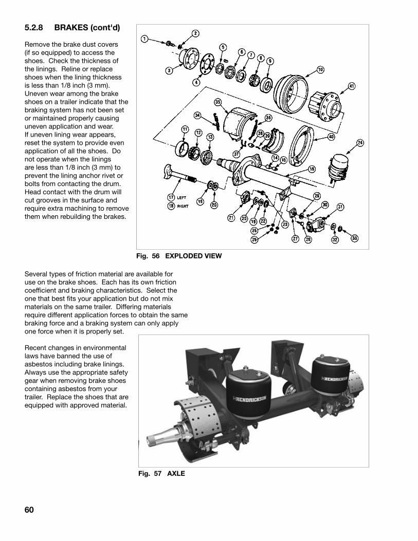
60
5.2.8 BRAKES (cont'd)
Remove the brake dust covers (if so equipped) to access the shoes. Check the thickness of the linings. Reline or replace shoes when the lining thickness is less than 1/8 inch (3 mm). Uneven wear among the brake shoes on a trailer indicate that the braking system has not been set or maintained properly causing uneven application and wear. If uneven lining wear appears, reset the system to provide even application of all the shoes. Do not operate when the linings are less than 1/8 inch (3 mm) to prevent the lining anchor rivet or bolts from contacting the drum. Head contact with the drum will cut grooves in the surface and require extra machining to remove them when rebuilding the brakes.
Several types of friction material are available for use on the brake shoes. Each has its own friction coefficient and braking characteristics. Select the one that best fits your application but do not mix materials on the same trailer. Differing materials require different application forces to obtain the same braking force and a braking system can only apply one force when it is properly set.
Recent changes in environmental laws have banned the use of asbestos including brake linings. Always use the appropriate safety gear when removing brake shoes containing asbestos from your trailer. Replace the shoes that are equipped with approved material.
Fig. 56 EXPLODED VIEW
Fig. 57 AXLE
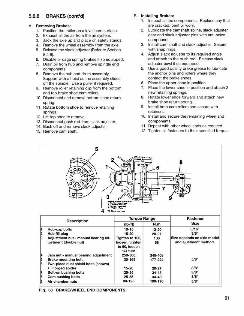
61
5.2.8 BRAKES (cont'd)
A. Removing Brakes: 1. Position the trailer on a level hard surface. 2. Exhaust all the air from the air system. 3. Jack the axle up and place on safety stands. 4. Remove the wheel assembly from the axle. 5. Release the slack adjuster (Refer to Section
5.2.6). 6. Disable or cage spring brakes if so equipped. 7. Drain oil from hub and remove spindle end
components. 8. Remove the hub and drum assembly.
Support with a hoist as the assembly slides off the spindle. Use a puller if required.
9. Remove roller retaining clip from the bottom and top brake shoe cam rollers.
10. Disconnect and remove bottom shoe return spring.
11. Rotate bottom shoe to remove retaining springs.
12. Lift top shoe to remove. 13. Disconnect push rod from slack adjuster. 14. Back off and remove slack adjuster. 15. Remove cam shaft.
B. Installing Brakes: 1. Inspect all the components. Replace any that
are cracked, bent or worn. 2. Lubricate the camshaft spline, slack adjuster
gear and slack adjuster pins with anti-seize compound.
3. Install cam shaft and slack adjuster. Secure with snap rings.
4. Adjust slack adjuster to its required angle and attach to the push rod. Release slack adjuster pawl if so equipped.
5. Use a good quality brake grease to lubricate the anchor pins and rollers where they contact the brake shoes.
6. Place the upper shoe in position. 7. Place the lower shoe in position and attach 2
new retaining springs. 8. Rotate lower shoe forward and attach new
brake shoe return spring. 9. Install both cam rollers and secure with
retainers. 10. Install and secure the remaining wheel and
components. 11. Repeat with other wheel ends as required. 12. Tighten all fasteners to their specified torque.
1. Hub-cap bolts2. Hub fill plug3. Adjustment nut - manual bearing ad-
justment (double nut)
4. Jam nut - manual bearing adjustment5. Brake mounting bolt6. Two-piece dust shield bolts (shown) • Forged spider7. Bolt-on bushing bolts8. Cam bushing bolts9. Air chamber nuts
10-1515-20
Tighten to 100, loosen, tighten to 50, loosen
1/4 turn 250-300130-165
15-2025-3525-35
80-125
5/16"3/8"
Size depends on axle model and ajustment method.
5/8"
3/8"3/8"3/8"5/8"
13-2020-2713668
340-408177-224
20-2734-4834-48
109-170
DescriptionTorque Range Fastener
Size (lb-ft) N.m
Fig. 58 BRAKE/WHEEL END COMPONENTS

62
5.2.9 SLACK ADJUSTERS
5.2.9.1 HALDEX AUTOMATIC SLACK ADJUSTER
The Haldex S-ABA automatic brake adjuster is a clearance sensing brake adjuster that maintains a nominal distance or clearance between lining and drum.
When the Adjuster is Installed:With the brake in the released position, the control arm is fixed to the anchor bracket.The adjustment hex is rotated until the shoes contact the brake drum and then backedoff 1/2 turn. When the brake is applied on the first application, the endless rack rotates to the correct position and sets itself.
When the Brake Applies:When the brake is applied, the adjustment regulator rotates through the normal clearance angle and the shoes contact the drum. The torque increases and the wormshaft is moved axially, causing the coilspring to be compressed and the clutch wheel to disengage. The adjustment components are free to rotate as the brake continues to apply.
When the Brake Releases:When the brake is released, the torque decreases returning the wormshaft to the clutch wheel and re-engaging the teeth. The adjustment regulator rotates through the normal clearance angle and the brake is released. If lining wear has taken place the adjustment regulator advances the clutch wheel reducing the excess clearance during the release
stroke.
Fig. 59 HALDEX SLACK ADJUSTER (TYPICAL)
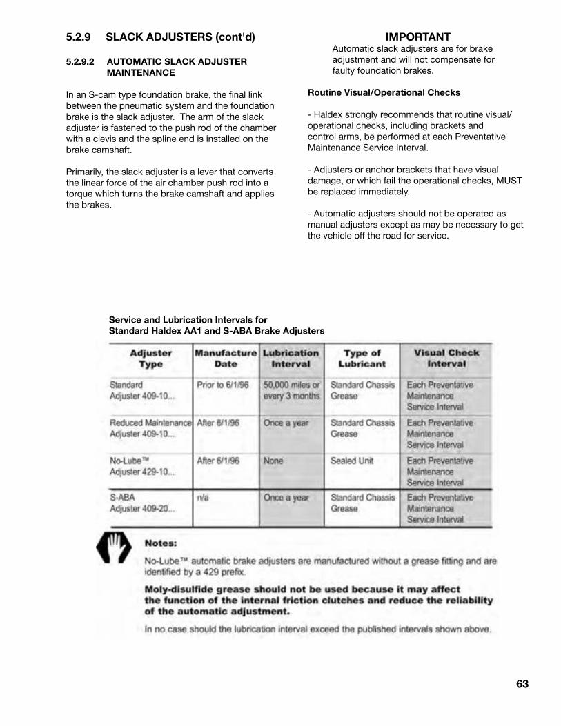
63
5.2.9 SLACK ADJUSTERS (cont'd)
5.2.9.2 AUTOMATIC SLACK ADJUSTER MAINTENANCE
In an S-cam type foundation brake, the final link between the pneumatic system and the foundation brake is the slack adjuster. The arm of the slack adjuster is fastened to the push rod of the chamber with a clevis and the spline end is installed on the brake camshaft.
Primarily, the slack adjuster is a lever that converts the linear force of the air chamber push rod into a torque which turns the brake camshaft and applies the brakes.
Service and Lubrication Intervals forStandard Haldex AA1 and S-ABA Brake Adjusters
IMPORTANTAutomatic slack adjusters are for brake adjustment and will not compensate for faulty foundation brakes.
Routine Visual/Operational Checks
- Haldex strongly recommends that routine visual/operational checks, including brackets and control arms, be performed at each Preventative Maintenance Service Interval.
- Adjusters or anchor brackets that have visual damage, or which fail the operational checks, MUST be replaced immediately.
- Automatic adjusters should not be operated as manual adjusters except as may be necessary to get the vehicle off the road for service.
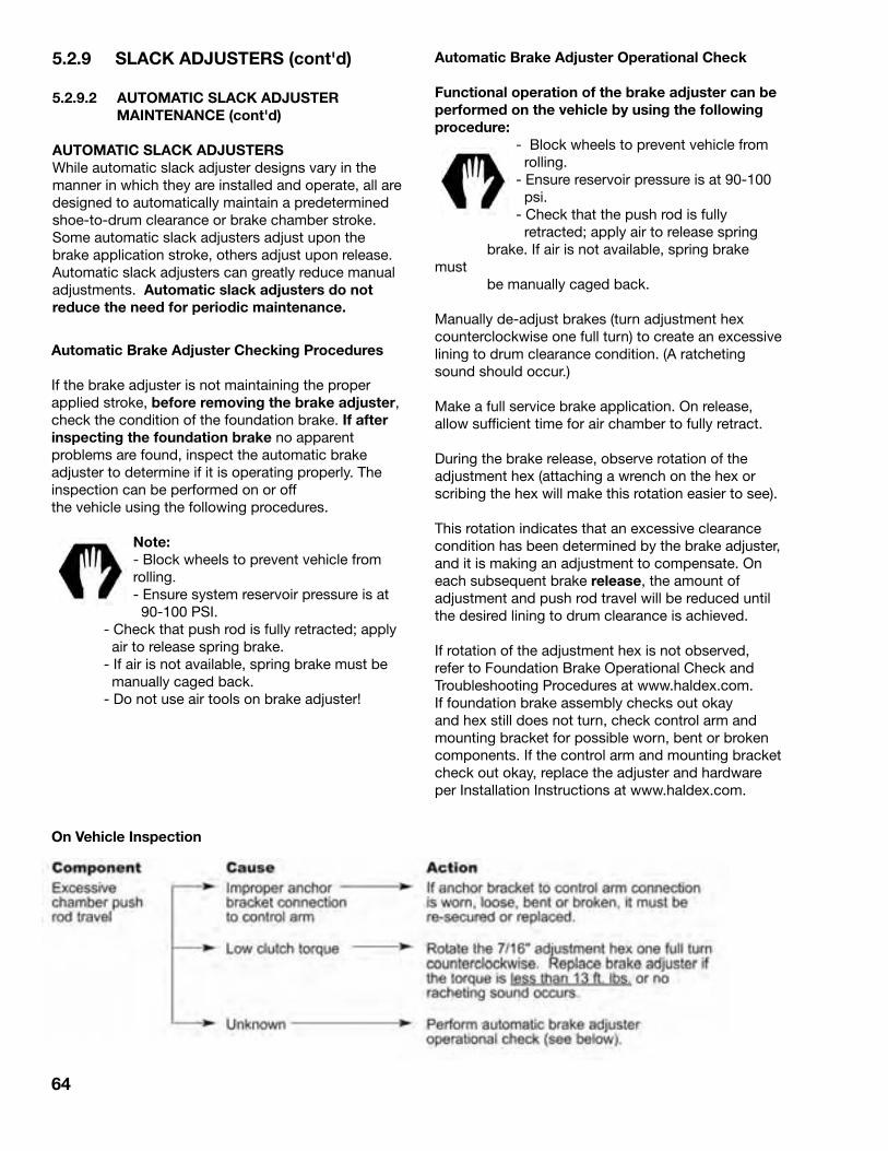
5.2.9 SLACK ADJUSTERS (cont'd)
5.2.9.2 AUTOMATIC SLACK ADJUSTER MAINTENANCE (cont'd)
AUTOMATIC SLACK ADJUSTERSWhile automatic slack adjuster designs vary in the manner in which they are installed and operate, all are designed to automatically maintain a predetermined shoe-to-drum clearance or brake chamber stroke. Some automatic slack adjusters adjust upon the brake application stroke, others adjust upon release. Automatic slack adjusters can greatly reduce manual adjustments. Automatic slack adjusters do not reduce the need for periodic maintenance.
64
Automatic Brake Adjuster Checking Procedures
If the brake adjuster is not maintaining the proper applied stroke, before removing the brake adjuster, check the condition of the foundation brake. If after inspecting the foundation brake no apparent problems are found, inspect the automatic brake adjuster to determine if it is operating properly. The inspection can be performed on or offthe vehicle using the following procedures.
Note: - Block wheels to prevent vehicle from
rolling. - Ensure system reservoir pressure is at 90-100 PSI. - Check that push rod is fully retracted; apply air to release spring brake. - If air is not available, spring brake must be manually caged back. - Do not use air tools on brake adjuster!
On Vehicle Inspection
Automatic Brake Adjuster Operational Check
Functional operation of the brake adjuster can be performed on the vehicle by using the following procedure: - Block wheels to prevent vehicle from
grolling. - Ensure reservoir pressure is at 90-100
gpsi.- Check that the push rod is fully gretracted; apply air to release spring
brake. If air is not available, spring brake must be manually caged back.
Manually de-adjust brakes (turn adjustment hex counterclockwise one full turn) to create an excessive lining to drum clearance condition. (A ratcheting sound should occur.)
Make a full service brake application. On release, allow sufficient time for air chamber to fully retract.
During the brake release, observe rotation of the adjustment hex (attaching a wrench on the hex or scribing the hex will make this rotation easier to see).
This rotation indicates that an excessive clearance condition has been determined by the brake adjuster, and it is making an adjustment to compensate. On each subsequent brake release, the amount of adjustment and push rod travel will be reduced until the desired lining to drum clearance is achieved.
If rotation of the adjustment hex is not observed, refer to Foundation Brake Operational Check and Troubleshooting Procedures at www.haldex.com. If foundation brake assembly checks out okay and hex still does not turn, check control arm and mounting bracket for possible worn, bent or broken components. If the control arm and mounting bracket check out okay, replace the adjuster and hardware per Installation Instructions at www.haldex.com.

65
5.2.9 SLACK ADJUSTERS (cont'd)
5.2.9.2 AUTOMATIC SLACK ADJUSTER MAINTENANCE (cont'd)
BRAKE ADJUSTMENT PROCEDURE
NOTEAll adjustments should be made with cold brake drums and the brakes fully released.
To avoid possible injury, proper precautions must be taken to prevent automatic actuation of the brake chambers while adjusting slack adjusters. Always block the wheels or me-chanically secure the vehicle. Spring brakes must be mechanically caged or released with air. All brakes should be released.
WARNING
Foundation Brake Operational Check and Troubleshooting
Note: - Block wheels to prevent vehicle from grolling.
- Ensure system reservoir pressure is at g90-100psi. - Check that push rod is fully retracted; apply air to release spring brake.
North American Commercial Vehicle Safety Alliance (CVSA) Uniform Vehicle Inspection CriteriaThe applied stroke of the brake should be checked per CVSA guidelines at 90-100 PSI reservoir pressure. Applied stroke should be at or less than the specified re-adjustment limits as follows:

66
5.2.9 SLACK ADJUSTERS (cont'd)
5.2.9.2 AUTOMATIC SLACK ADJUSTER MAINTENANCE (cont'd)
Free Stroke
Measuring the Free Stroke Free stroke is the amount of movement of the adjuster arm required to move the brake shoes against the drum. With brakes released, measure from the face of the chamber to the center of the clevis pin “A” (fig. 13). Use a lever to move the brake adjuster until the brake shoes contact the drum “B” (fig. 13). The difference between the fully retracted and drum contact measurement “B”–“A” (fig. 13), is the free stroke. The free stroke range should fall between 3/8"–3/4".
Free Stroke Within RangeIf the free stroke is good, but the applied stroke is too long, there is probably a problem with the foundation brake. Check the following and reference CVSA out-of-service criteria:

67
5.2.9 SLACK ADJUSTERS (cont'd)
5.2.9.2 AUTOMATIC SLACK ADJUSTER MAINTENANCE (cont'd)
Free Stroke Above the Range If the free stroke is above the range and the applied stroke is too long, there is a problem with the foundation brake or the adjuster. Check the following:
A(Fully Retracted)
B(Drum Contact Using a Lever)
C(Brake Application at 90-100 PSI
reservoir pressure.)
Free Stroke = B minus AApplied Stroke = C minus A
Figure13 Stroke Measurements (taken from face of air chamber to center of clevis pin)
Free Stroke Above the Range
If the free stroke is above the range and the applied stroke is too long, there is a problem with the foundation brake or the adjuster. Check the following:
Component Cause ActionCamshaft Binding Remove, replace, lubricate camshaftCamshaft bushings Excessive movement Remove and replace cam bushings per OEM specsCamshaft bushings Binding shaft Lubricate camshaft bushings or replaceAir chamber return springs Broken, weak, missing Replace chamberAir chamber push rod Binding on chamber housing Check adjuster for proper shimming and air chamber
position for proper adjuster arm lengthAir system Not exhausting completely Check for cause of air problem and repairShoe return springs Broken, weak, missing Replace springsAutomatic brake adjuster Unknown Check automatic brake adjuster for proper
installation. Refer to Installation Instructions at
Automatic brake adjuster Unknown Refer to Automatic Brake Adjuster Checking Procedures and Operational Check at www.haldex.com.
Free Stroke Below the RangeIf the free stroke is less than 3/8”, a dragging brake can occur. Check the following:
Component Cause ActionWheel bearing Out of adjustment Readjust per OEM specsAutomatic brake adjuster Unknown Check automatic brake adjuster for proper control
arm position. Refer to Installation Instructions at
Automatic brake adjuster Unknown Refer to Automatic Brake Adjuster Checking Procedures and Operational Check .
8
www.haldex.com.
www.haldex.com.
at www.haldex.com
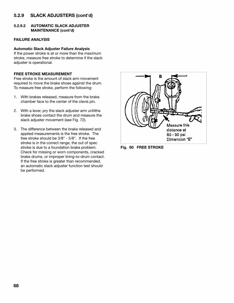
68
5.2.9 SLACK ADJUSTERS (cont'd)
5.2.9.2 AUTOMATIC SLACK ADJUSTER MAINTENANCE (cont'd)
FAILURE ANALYSIS
Automatic Slack Adjuster Failure AnalysisIf the power stroke is at or more than the maximum stroke, measure free stroke to determine if the slack adjuster is operational.
FREE STROKE MEASUREMENTFree stroke is the amount of slack arm movement required to move the brake shoes against the drum. To measure free stroke, perform the following:
1. With brakes released, measure from the brake chamber face to the center of the clevis pin.
2. With a lever, pry the slack adjuster arm untilthe brake shoes contact the drum and measure the slack adjuster movement (see Fig. 72).
3. The difference between the brake released and applied measurements is the free stroke. The free stroke should be 3/8" - 5/8". If the free stroke is in the correct range, the out of spec stroke is due to a foundation brake problem. Check for missing or worn components, cracked brake drums, or improper lining-to-drum contact. If the free stroke is greater than recommended, an automatic slack adjuster function test should be performed.
Fig. 60 FREE STROKE

69
5.2.10 TRAILER ABS
Each trailer is designed with an ABS (Automatic Braking System) to increase the effectiveness of the brakes during stopping. The system consists of valves, sensors, exciter rings and an Electric Control Unit.
Review the brochures included in the documentation package to become familiar with the ABS system and installation. The system is installed on each axle and controlled by the air system.
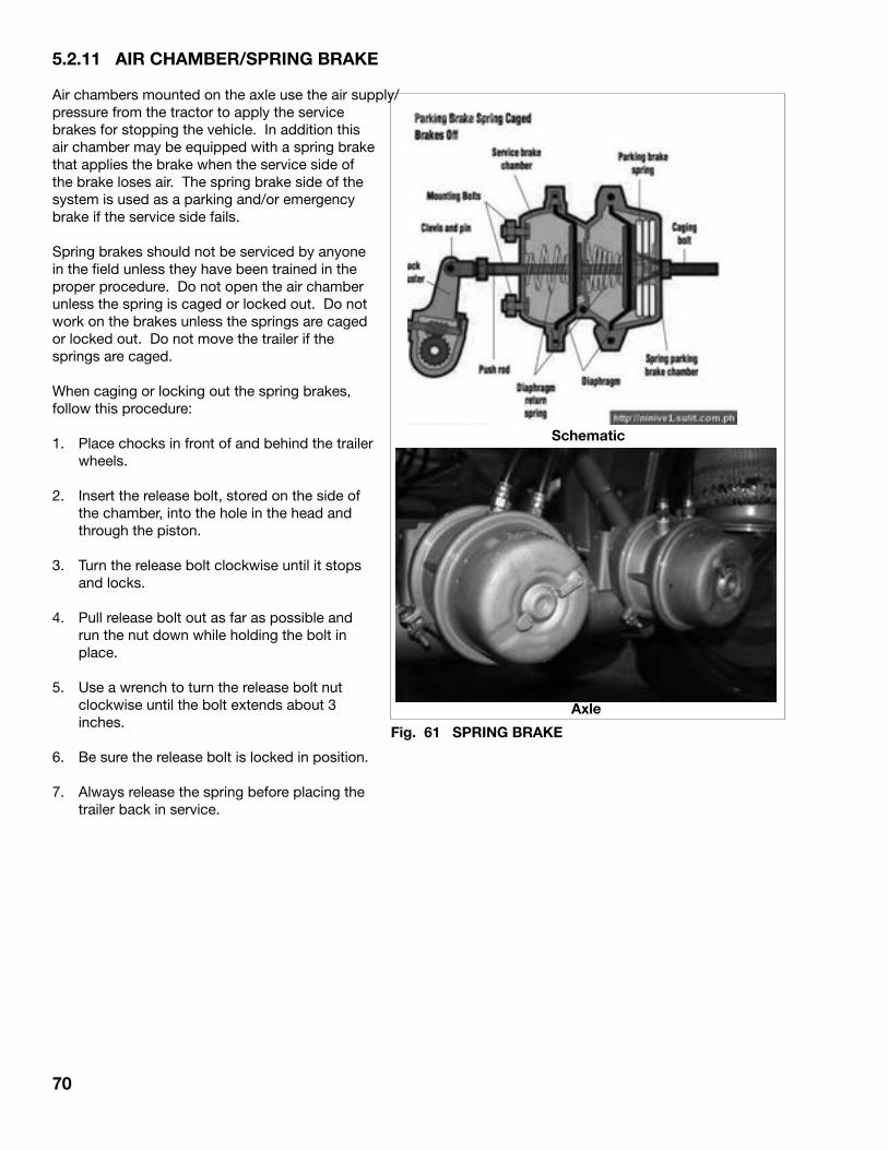
5.2.11 AIR CHAMBER/SPRING BRAKE
Air chambers mounted on the axle use the air supply/pressure from the tractor to apply the service brakes for stopping the vehicle. In addition this air chamber may be equipped with a spring brake that applies the brake when the service side of the brake loses air. The spring brake side of the system is used as a parking and/or emergency brake if the service side fails.
Spring brakes should not be serviced by anyone in the field unless they have been trained in the proper procedure. Do not open the air chamber unless the spring is caged or locked out. Do not work on the brakes unless the springs are caged or locked out. Do not move the trailer if the springs are caged.
When caging or locking out the spring brakes, follow this procedure:
1. Place chocks in front of and behind the trailer wheels.
2. Insert the release bolt, stored on the side of the chamber, into the hole in the head and through the piston.
3. Turn the release bolt clockwise until it stops and locks.
4. Pull release bolt out as far as possible and run the nut down while holding the bolt in place.
5. Use a wrench to turn the release bolt nut clockwise until the bolt extends about 3 inches.
6. Be sure the release bolt is locked in position.
7. Always release the spring before placing the trailer back in service.
Axle
Schematic
70
Fig. 61 SPRING BRAKE

71
5.2.12 SUSPENSION SYSTEM
The suspension system is the group of components that connect the axle to the main trailer frame and absorb the shock loads from the road. Midland trailers can be equipped with either a mechanical or air ride suspension system. Either system works well and will provide many years of trouble-free service.
5.2.21.1 AIR RIDE SUSPENSION
An air ride suspension consists of air springs that are inflated and pressurized by the trailer air system and controlled by a height control valve. It is a simple system that requires minimal servicing and maintenance to perform well.
Visually inspect the trailer at the start of the day or trip to check the condition of the suspension. Ensure that the ride height is set as per proper specifications. Also, check for loose fasteners or damaged components. Correct any problems before placing the trailer into service. Problems caught early and corrected minimize cost and downtime.
Every 5,000 miles (8,000 km) or monthly, check the clearance around all the suspension system components. Correct any interference problem. Retorque all the fasteners to their specified torque.
Every 25,000 miles (40,000 km) or 3 months, visually inspect all components and welds for cracks, distortions or other damage. Repair or replace all defective components before placing unit into service.
Fig. 62 HENDRICKSON SUSPENSION BOLT TORQUE VALUES
Fig. 63 RIDEWELL SUSPENSION BOLT TORQUE VALUES
72
2. Shock Absorber Replacement: Shock absorbers remove energy from the
suspension system as the trailer encounters holes and bumps on the road surface. They also act as a stop for the air springs to prevent the axle from moving too far away from the frame and tearing or damaging the air spring.
a. Remove the upper and lower mounting bolts.
b. Remove old shock and install new one.
c. Secure shock by tightening mounting bolts to their specified torque of 250 ft. lbs. (338 N.m).
IMPORTANTUse only correct manufacturer specific components replacement parts. Substitute parts do not work with the suspension system.
3. Pivot Bushing: For pivot bushing replacements please see your
dealer or trailer repair shop.
5.2.12 SUSPENSION SYSTEM (cont'd)
5.2.12.1 AIR RIDE SUSPENSION (cont'd)
Typical repairs include but are not limited to:
1. Air Spring Replacement: Air springs are designed to be virtually trouble-
free throughout their life. Problems seldom occur unless they are cut, punctured, abraded, pinched or torn and then they must be replaced.
a. Block the wheels to prevent trailer movement.
b. Exhaust air from the suspension system.
c. Raise and support the frame on safety stands.
d. Disconnect the air lines to the air spring(s).
NOTEDo not raise frame too high unless shock absorbers are installed to prevent over-extending the air spring.
e. Loosen mounting bolts and remove air spring(s).
f. Install new air spring(s).
g. Tighten mounting bolts to their specified torque of 50 ft. lbs. (68 N.m).
h. Install air lines and tighten to their specified torque.
i. Repeat on other air springs.
j. Remove stands from under frame.

73
5.2.12 SUSPENSION SYSTEM (cont'd)
5.2.12.1 AIR RIDE SUSPENSION (cont'd)
4. Air Control (Ride Height Control): An air ride suspension system uses the air
from the tractor to pressurize the air springs. A single height control valve is used to monitor the height of the frame above the axle and add/exhaust air from the system as required to maintain this dimension. Normally this dimension is set for your trailer and seldom changes.
The height control valve is located on one of the axles and controls the adding/exhausting of air to the air springs. As the dimension between the frame and axle increases, the control lever moves down and air is exhausted from the system. As the dimension decreases, air is added to raise the frame. All valves incorporate a 5 to 15 second time delay to minimize jerking or cycling. Replace valve if not functioning properly.
Check ride height after first use and periodically thereafter to maintain proper ride height. Improper ride height can cause severe component damage and void your warranty. Maintaining correct ride height is the responsibility of the operator.
There are two different ride heights (15" and 17"). All trailers with the exception of B-Train Lead are 17" ride height. The B-Train Lead is 15". This measurement is taken from the center of the axle to the underside of the frame.
NOTEMeasure the axle that has the ride height control mounted to it. The other axle(s) may have more or less distance between the frame and axle depending on the height of fifth wheel. If ride height is incorrect contact your dealer.
Valve Schematic
System Schematic
Valve
Fig. 64 RIDE HEIGHT CONTROL
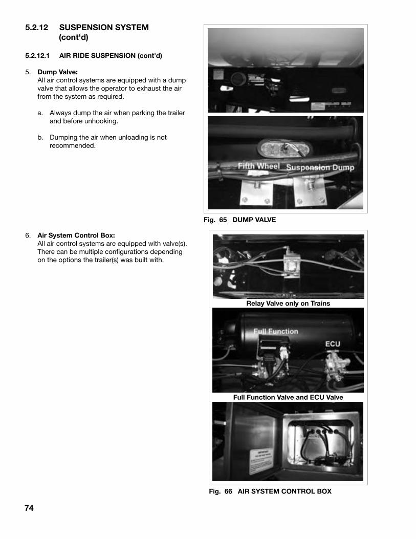
74
5.2.12 SUSPENSION SYSTEM (cont'd)
5.2.12.1 AIR RIDE SUSPENSION (cont'd)
5. Dump Valve: All air control systems are equipped with a dump
valve that allows the operator to exhaust the air from the system as required.
a. Always dump the air when parking the trailer and before unhooking.
b. Dumping the air when unloading is not recommended.
6. Air System Control Box: All air control systems are equipped with valve(s).
There can be multiple configurations depending on the options the trailer(s) was built with.
Relay Valve only on Trains
Fig. 65 DUMP VALVE
Fig. 66 AIR SYSTEM CONTROL BOX
Full Function Valve and ECU Valve

REYCO 21B LEAF SPRING SUSPENSION
75
5.2.12 SUSPENSION SYSTEM (cont'd)
5.2.12.2 MECHANICAL SUSPENSION
Two types of mechanical suspensions are available on the trailer and must be specified and ordered from the factory. Both work well and provide the customer with a choice.
The two types of suspension for the tandem and triaxle models are the Reyco 21B 8 leaf and the Hutch 9700 3 leaf. Both are designed to require minimal service and maintenance on a trailer. However, these service intervals and maintenance procedures must be followed:
Service Intervals:
1. Follow the break-in procedure specified in Section 4.3.
2. Visually inspect the suspension at the start of the day or trip for bent, broken or loose components. Always correct these conditions and perform a complete check-out of the suspension before placing the trailer back in service.
3. After each additional 25,000 miles (40,000 km), or every 3 months, retorque all the fasteners to their specified torque per the following table. Always use an accurate torque wrench when retorquing fasteners and attach to the nut.
4. 25,000 miles (40,000 km) or every 3 months, inspect the following:
a. Check position of clamp if moveable clamps used. Clamping legs must be centered over slot in end tube.
b. Check fit and function of all bushings.
c. Check all hanger and hanger bracing welds for cracks.
d. Check all other welds for signs of cracks or distortion.
e. Check fit of springs in hangers and equalizers.
f. Check equalizers for excessive wear at spring ends.
g. Check suspension system alignment.
5. In addition to checking the alignment at the recommended intervals, axle alignment should be checked when any of the following conditions occur:
a. Discovery of loose fasteners or components.
IMPORTANTA loose fastener is defined as one whose torque has dropped below its specified level.
b. Discovery of elongated holes in a suspension system component.
c. Whenever bushings are replaced.
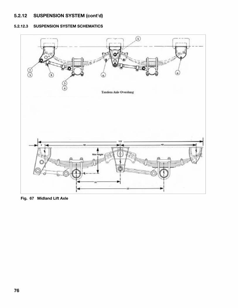
76
5.2.12 SUSPENSION SYSTEM (cont'd)
5.2.12.3 SUSPENSION SYSTEM SCHEMATICS
Fig. 67 Midland Lift Axle

77
5.2.13 AIR SYSTEM
Trailers are equipped with an air system, that is pressurized by a compressor on the tractor, for operating the "discharge gates", brakes and air suspension (if so equipped). All components must be in good condition for the system to function and perform as intended. The air system must be inspected to be kept in good condition and functional checks performed to be sure it is operating as required.
5.2.13.1 AIR SYSTEM INSPECTION
The pre-trip or pre-start inspection include several air system related checks, inspections or tasks including but not limited to:
Daily1. Check that the glad hands are clean and in good
condition. Check seals in glad hand Clean, repair or replace as required.
2. Check that the air hoses between the tractor and the trailer are routed to prevent rubbing, chaffing or pinching. Reroute to correct condition if required.
3. Drain moisture from all air tanks. Pull on the cable attached to drain valve on the bottom of each tank until the water or spray no longer can be seen.
IMPORTANTTanks must be drained daily in high humidity and cold temperature conditions to prevent getting water or ice in the system. During cold weather operation use only recommended air line anti freeze in the trailer air system. Alcohol or methyl hydrate is not to be used because they will remove vital lubricants causing premature failures of valves and components. Traces of these products will void any warranty consideration.
4. Check that all the lines and hoses conveying air along the frame are tied up and secured to prevent dragging, scuffing or snagging. Tie up or protect as required to correct the condition. Damaging an air system component can cause a sudden loss of pressure and result in a loss of service brakes.
IMPORTANTNew FMVSS-121 regulations mandate higher pressures in the supply line to insure proper brake operation. Set the compressor pressure for cut-in to 105 psi and cut-out to 120 psi. Do not use additives in the air systems.system.
5.2.13.2 AIR SYSTEM FUNCTIONAL
A vehicle air system is a combination of the components on the tractor and the trailer. All must be maintained in good condition for the entire system to function as required. Although a visual check will indicate the outer condition of the components, it does not indicate the leaks or responsiveness of the system. To evaluate the integrity and responsiveness of the system, perform these functional checks:
1. Attach the trailer to a tractor and connect all the air and electrical lines.
2. Block wheels.
3. Stop tractor engine and exhaust air from all tanks.
4. Start engine and run at fast idle (1200-1500 RPM) to charge the air system.
Verify that: a. Low pressure alarm goes off when the
system pressure drops below 50 psi. b. Increasing the system pressure between 50
psi and 80 psi takes less than 3 minutes. c. The compressor cuts out when the system
pressure drops below 120 psi. d. Fan brakes to use air. Compressor must
engage when system pressure drops below 105 psi.
NOTERelease spring brakes before fanning service brakes.
5. Push emergency valve to charge trailer system. Apply and release service brakes.
6. Build system up to 120 psi and stop engine.
Verify that: a. Main tank pressure does not drop more than
18 psi when brakes are fully applied using brake pedal. If pressure drop exceeds 18 psi, adjust brakes and recheck.
b. System pressure should not drop more than 4
psi per minute. Listen for audible leaks. c. Release foot valve to drop main reservoir
pressure. Brakes should dynamite automatically when the pressure drops below 60 psi.
Adjust or repair system until these conditions are met.

78
5.2.14 ELECTRICAL SYSTEM
All trailers are equipped with an electrical system for providing power for lights and electrical controls. All components are designed to minimize the effects of foul weather and adverse operating conditions. However, it is the responsibility of the operator to check and verify that all components are in good condition and functioning as intended.
During the daily or pre-trip inspection, always verify that each light functions as required. It may be helpful to work with another individual to verify the function of the brake or turn signal lights. A properly functioning electrical system is the only way an operator can communicate his intentions to other drivers. Checking the electrical system includes but is not limited to:
1. Replace any bulb that is burned out.
2. Clean all reflective lenses. Replace any that are cracked or broken.
3. Clean all connections and terminals to a light that is flickering.
4. Reroute and secure any wires or cables that are dangling or have snagged on something.
5. Check the integrity of the seal around each light. Replace any seal that is cracked or damaged.
Function
Table 11 Trailer Light Requirements
Size (Watts)
8
27
27
8
5
P/N
Tail Lamp
Signal/Brake
Side Signal
Clearance
Marker
Electrical Connectors
Side Signal
Rear
Subject to change based on design & model.
Fig. 68 LIGHTING

79
6 TROUBLE SHOOTING
In the following section, we have listed problems, causes and solutions to the problems that you may encounter.
If you encounter a problem that is difficult to solve, even after having read through this trouble shooting section and through the specifically related components manufacturer's manuals. please call your local Midland dealer or distributor. Before you call, please have this Operator's Manual and the serial numbers from your trailer ready.
PROBLEM CAUSE SOLUTION
Trailer out of alignment. Realign per procedure provided by the suspension manufacturer.
Trailer "Dog-Tracks"...

80
PROBLEM CAUSE SOLUTION
Tires
High or uneven tire wear.
Scuffed tires.
Wobbly tires.
Dog tracking.
Loss of tire air pressure.
Inflate to proper pressure.
Tighten wheel stud nuts or clamps.
Adjust bearings.
Straighten, align or replace axle.
Match tires.
Correct brakes as required.
Apply brakes slowly when approaching stops.
Reduce speed.
Inflate to proper pressure.
Reduce speed.
Torque tighten all rim clamps.
Replace bearings.
Replace wheel or rim.
Replace or straighten axle.
Replace leaf or complete spring.
Replace or straighten axle.
Straighten frame or align axles.
Repair or replace tire.
Replace valve assembly or core.
Replace wheel or rim.
Over or under inflation.
Loose wheel stud nuts or clamps.
Loose or tight wheel bearing.
Axle bent or out of alignment.
Tires not properly matched.
Improper acting brakes.
Rapid stopping.
High speed.
Over or under inflation.
Excessive speed on turns.
Tire wobble due to uneven rim clamping.
Worn or damaged wheel bearings.
Bent wheel or rim.
Bent axle.
Leaf spring broken.
Bent axle.
Frame or suspension (axles) out of alignment.
Puncture in tire.
Faulty valve or valve core.
Wheel or rim damage.

81
PROBLEM CAUSE SOLUTION
Electrical
Check electrical system circuits.
Repair as required.
Charge battery.
Repair or replace cable.
Repair as necessary.
Repair or replace.
Replace junction box.
Repair as required.
Repair or replace cable as required.
Repair or replace.
Replace junction box.
Bad connection.
Frayed wires.
Battery on tractor not sufficiently charged.
Damaged or disconnected wire on ground cable.
Poor ground at sockets.
Broken main harness.
Junction box failure.
Frayed wires.
Damaged or disconnectedground cable.
Loose or corroded connection in ground lead between tractor and trailer.
Internal short in junction box.
Lights flicker or do not come on.
Complete loss of trailer lights.
Lights flash improperly or appear to be crossed.

82
PROBLEM CAUSE SOLUTION
Air System
Excessive compressor cycling.
Trailer brakes slow and sluggish.
Air leak.
System or component failure.
Check air line fittings and hose connections on service or supply line.
Check service chamber at clamp housing, push rod for damage.
Check service chamber diaphragm.
Check emergency chamber clamp and vent holes for leakage.
Repair or replace air chamber as required.
Check FFVII brake valve. Repair or replace as required.
Check slack adjuster and chamber/spring brake push rod alignment for interference.
Assure slack adjuster and chamber/spring brake push rod angle 90° applied with proper adjustment.
Assure open lines - no kinks, bends, closed shut-off cocks, restrictions, excessive elbows.
Assure adequate tractor brake function.
Have authorized service center check for adequate pressure and timing balance relative to tractor/trailer application.
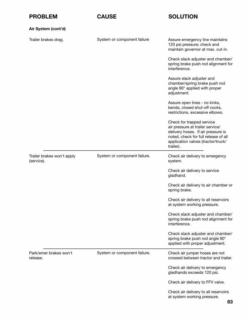
83
PROBLEM CAUSE SOLUTION
Air System (cont'd)
Trailer brakes drag.
Trailer brakes won't apply (service).
Park/emer brakes won't release.
System or component failure
System or component failure.
System or component failure.
Assure emergency line maintains 120 psi pressure; check and maintain governor at max. cut-in.
Check slack adjuster and chamber/spring brake push rod alignment for interference.
Assure slack adjuster and chamber/spring brake push rod angle 90° applied with proper adjustment.
Assure open lines - no kinks, bends, closed shut-off cocks, restrictions, excessive elbows.
Check for trapped service air pressure at trailer service/delivery hoses. If air pressure is noted, check for full release of all application valves (tractor/truck/trailer).
Check air delivery to emergency system.
Check air delivery to service gladhand.
Check air delivery to air chamber or spring brake.
Check air delivery to all reservoirs at system working pressure.
Check slack adjuster and chamber/spring brake push rod alignment for interference.
Check slack adjuster and chamber/spring brake push rod angle 90° applied with proper adjustment.
Check air jumper hoses are not crossed between tractor and trailer.
Check air delivery to emergency gladhands exceeds 120 psi.
Check air delivery to FFV valve.
Check air delivery to all reservoirs at system working pressure.

84
PROBLEM CAUSE SOLUTION
Air System (cont'd)
Park/emer brakes won't release (cont'd).
Park/emer brakes won't hold.
Air reservoir leaks or loose mounting.
Semi-trailer "Runs-Up" on tractor.
Poor braking performance.
System or component failure (cont'd).
System or component failure.
System or component failure.
Check brake linkage.
Uneven brakes.
Check open lines - no kinks, bends, closed shut-off cocks, restrictions, excessive elbows.
Check that brake shoes are not frozen to drums.
Check slack adjuster and chamber/spring brake push rod alignment for interference.
Assure slack adjuster and chamber/spring brake push rod angle 90° applied with proper adjustment.
Replace/use rubber grommets with integral brackets.
Assure slack adjuster and chamber/spring brake push rod angle 90° applied with proper adjustment.
Check gladhand connection.
Assure open lines - no kinks, bends, closed shut-off cocks, restrictions, excessive elbows.
Have authorized service center check for adequate pressure and timing balance relative to tractor/trailer application.
Check slack adjuster and chamber/spring brake push rod angle 90° applied with proper adjustment.
Check slack adjuster and chamber/spring brake push rod angle 90° applied with proper adjustment.
Check open lines - no kinks, bends, closed shut-off cocks, restrictions, excessive elbows.
Check a leak free system by applying service brake and inspecting.
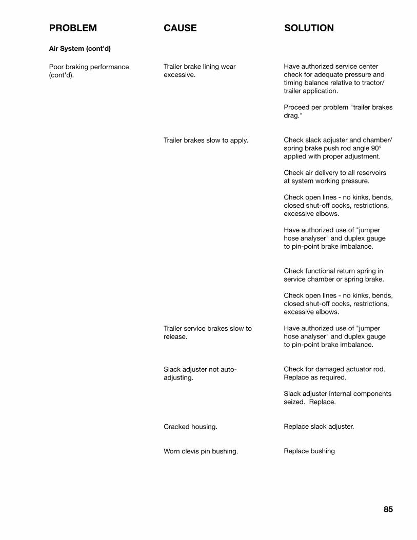
85
PROBLEM CAUSE SOLUTION
Air System (cont'd)
Poor braking performance (cont'd).
Trailer brake lining wear excessive.
Trailer brakes slow to apply.
Trailer service brakes slow to release.
Slack adjuster not auto-adjusting.
Cracked housing.
Worn clevis pin bushing.
Have authorized service center check for adequate pressure and timing balance relative to tractor/trailer application.
Proceed per problem "trailer brakes drag."
Check slack adjuster and chamber/spring brake push rod angle 90° applied with proper adjustment.
Check air delivery to all reservoirs at system working pressure.
Check open lines - no kinks, bends, closed shut-off cocks, restrictions, excessive elbows.
Have authorized use of "jumper hose analyser" and duplex gauge to pin-point brake imbalance.
Check functional return spring in service chamber or spring brake.
Check open lines - no kinks, bends, closed shut-off cocks, restrictions, excessive elbows.
Have authorized use of "jumper hose analyser" and duplex gauge to pin-point brake imbalance.
Check for damaged actuator rod. Replace as required.
Slack adjuster internal components seized. Replace.
Replace slack adjuster.
Replace bushing

86
PROBLEM CAUSE SOLUTION
Air System (cont'd)
Poor braking performance (cont'd).
Full function valve (FFV) leaks at exhaust port with all brakes released.
Full function valve (FFV) leaks at exhaust port with service brakes applied.
Spring parking brake (service only service chamber side of spring brake) drags or won't release.
Spring parking brake (service only service chamber side of spring brake) leaks when pressurized for park brake release.
Replace FFV valve.
Replace FFV valve.
Check for:- Improper adjustment, restriction
or broken line.- Diaphragm failure.- System pressure too low (120 psi
min).- Improper manual release.- Broken return spring (spring
side).- Broken power spring.- Replace entire unit or piggy-back
emergency section.
Check for:- Ruptured spring side diaphragm.- Hose leaks.

87
7 BOLT TORQUE
7.1 BOLT TORQUE
CHECKING BOLT TORQUE
The tables shown below give correct torque values for various bolts and capscrews. Tighten all bolts to the torques specified in chart unless otherwise noted. Check tightness of bolts periodically, using bolt torque chart as a guide. Replace hardware with the same strength bolt.
ENGLISH TORQUE SPECIFICATIONS
SAE 2(N.m) (lb-ft)
Bolt Torque*Bolt
Diameter"A"
SAE 5(N.m) (lb-ft)
SAE 8(N.m) (lb-ft)
1/4"5/16"3/8"7/16"1/2"9/16"5/8"3/4"7/8"1"
81327416195128225230345
6102030456095165170225
12254572110155215390570850
919335380115160290420630
1736631001552203055408801320
12274575115165220400650970
METRIC TORQUE SPECIFICATIONS
8.8(N.m) (lb-ft)
Bolt Torque*Bolt
Diameter"A"
10.9(N.m) (lb-ft)
M3M4M5M6M8M10M12M14M16M20M24M30M36
.5361025509014022543575014952600
.42.24718376610316632155311031917
1.84.59153570125200310610105021003675
1.33.371126529214822945077415502710
Torque figures indicated above are valid for non-greased or non-oiled threads and heads unless otherwise specified. Therefore, do not grease or oil bolts or capscrews unless otherwise specified in this manual. When using locking elements, increase torque values by 5%.
* Torque value for bolts and capscrews are identified by their head markings.

88
8 INDEX
PAGE PAGE
Bolt Torque ....................................................87
S
Safety ..............................................................2 General Safety ............................................3 Hydraulic Safety .........................................5 Loading Safety ...........................................5 Maintenance Safety ....................................4 Operating Safety ........................................4 Safety Signs/Decals ...................................6 Sign-Off Form .............................................7 Tire Safety ..................................................6 Travel Safety ...............................................5Safety Sign (Decal) Locations .........................8Service and Maintenance ..............................30 Periodic Maintenance and Adjustments ..45 Air Chamber/Spring Brake ..................70 Air System ..........................................77 Air System Functional ....................77 Air System Inspection ....................77 Axle Alignment ....................................49 Brakes .................................................59 Electrical System .................................78 Fifth Wheel ..........................................48 Kingpin and Anchor Frame ..................47 Slack Adjusters ....................................62 Automatic Slack Adjuster ..........................................62 Automatic Slack Adjuster Maintenance ....................63 Suspension System .............................71 Air Ride Suspension .......................71 Mechanical Suspension .................75 Suspension System Schematics ....76 Tires .....................................................57 Torque Specification Summary ...........45 Trailer ABS ...........................................69 Wheels .................................................55 Wheel Hubs/Bearings ..........................51 Service ......................................................30 Fluids and Lubricants ..........................30 Greasing ..............................................30 Service Record Summary (Lube) .........44 Servicing Intervals ...............................31
O
Operation Guidelines .....................................10 Break-In ....................................................12 Controls ....................................................14 Hooking Up/Unhooking ............................21 Hooking Up .........................................21 Unhooking ...........................................23 Loading/Unloading ...................................24 Pre-Operation Vehicle Inspection Procedure ............................................18 Terminology ..............................................11 To the New Operator or Owner ................10 Transporting .............................................27 Braking Guidelines ..............................28 Operating Instructions .........................27 Tires .....................................................29
T
Trouble Shooting ...........................................79
B
Introduction .....................................................1
I
PRINTED IN CANADAISSUE DATE: JANUARY, 2002REPRINT: PART NUMBER: 0400000
MIDLAND MANUFACTURING LIMITEDBOX 249
ROSENORT, MANITOBACANADA, R0G 1W0
PHONE (204) 746-2348TOLL FREE 1-800-827-7023
FAX (204) 746-2286www.midlandtrailers.com