side- stern thruster power manual - · pdf fileminimum is hulls bottom thickness of motor. c...
TRANSCRIPT

Mad
e in
Nor
way
© Sleipner Motor AS 2005
® Stern thrusterinstallationmanual
SIDE-POWER
SLEIPNER MOTOR ASP.O. Box 519N-1612 FredrikstadNorwayTel: +47 69 30 00 60Fax:+47 69 30 00 70
Keep this
manual onboard !IMPORTANT NOTICE:
This manual is to be used in addition to the regularinstallation manual for the Sidepower thruster.
This manual is intended for professionals only, anddoes not contain all detailed work instructions for
what must be done to ensure correct and safeinstallation of the sternthruster.
© SLEIPNER MOTOR AS - 2009

Installation
To achieve maximum effect, reliability and durability from your Sidepower Sternthruster, a correct installation is veryimportant.
Please follow the instructions carefully, and make sure that all checkpoints are carefully controlled.
1. Make sure that there are enough space both inside and outside the transom of the boat (see FIG 1).
Outside of flange:E
Cut out in stern:F
Bolt holes dia : GBolt postion radius : H
60°
D
A
PS !Necessarysupportof motor.
Min
imum
ishu
lls b
otto
mth
ickn
ess
C B
W.L.
FIG. 1
Stern thruster installation manual Version 1.6 - 20052
Additional considerations for positioning of stern thruster. Make sure that the stern-tunnel does not disturb the waterflow under the hull Ensure that when installed the thruster does not foul exisiting equipment inside the boat like steerage links etc. It is essential that the motor is supported so that the total weight is not on the tunnel alone. Make sure that the water flow from the thruster are not intereferred to much by sterndrives, trimtabs etc. as this
will reduce the thrust considerably. It is possible to mount the tunnel off the boat’s centre line if necessary. If the stern thickness is to much for the thruster in question you can easily remove material in the necessary area
to fit the thruster. The stern thickness even here will never have to be less than the max. measurement given asmax. stern thickness.
Measurements ref.mm / inch SP30Si / SP40Si SP55Si SP75Ti SP95Ti SP125Ti SP155TCi SP200TCi
SP200TCi-32 / SP240TCi SP285TCi
A 200mm / 7,87'' 225mm / 8,90" 312mm / 12,30" 349mm / 13,70" 363mm / 15,10" 386mm / 15,20" 419mm / 16,50" 440mm / 17,30" 404mm / 15,90"
B 190mm / 7,48'' 256mm / 10,08" 256mm / 10,08" 256mm / 10,08" 340mm / 13,39" 340mm / 13,39" 360mm / 14,20" 420mm / 16,54" 420mm / 16,54"
C 135mm / 5,31'' 150mm /5,91" 200mm / 7,87" 200mm / 7,87" 250mm / 9,84" 250mm / 9,84" 300mm / 11,81" 300mm / 11,81" 300mm / 11,81"
D 197mm / 7,76'' 337mm / 13,30" 337mm / 13,30" 337mm / 13,30" 350mm / 13,80" 350mm / 13,80" 350mm / 13,80" 456mm / 18,00" 456mm / 18,00"
E ø217mm / 8,54'' ø300mm / 11,80" ø300mm / 11,80" ø300mm / 11,80" ø300mm / 11,80" ø300mm / 11,80" 356mm / 14,02" ø396mm / 15,60" ø396mm / 15,60"
F ø160mm / 6,30'' ø200mm / 7,84" ø200mm / 7,84" ø200mm / 7,84" ø200mm / 7,84" ø200mm / 7,84" ø260mm / 11,24" ø265mm / 10,40" ø265mm / 10,40"
G 6 x ø6,5mm / 0,26'' 6x ø10,5mm / 0,41" 6x ø10,5mm / 0,41" 6x ø10,5mm / 0,41" 6x ø10,5mm / 0,41" 6x ø10,5mm / 0,41" 8x ø10,5mm / 0,41" 8x ø10,5mm / 0,41" 8x ø10,5mm / 0,41"
H ø98mm / 3,86'' ø129mm / 5,08" ø129mm / 5,08" ø129mm / 5,08" ø129mm / 5,08" ø129mm / 5,08" ø315mm / 12,40" ø345,6mm / 13,60" ø345,6mm / 13,60"Max. Stern thickness 14mm / 0,55'' 35mm / 1,38" 54mm / 2,13" 54mm / 2,13" 60mm / 2,36" 60mm / 2,36" 50mm / 1,97" 60mm / 2,36" 60mm / 2,36"
Measurements ref.mm / inch SP100HYD SP220HYD SP300HYD SP550HYD
A 158mm / 6,22" 178mm / 7,01" 208mm / 8,19" 259mm / 10,20"
B 256mm / 10,08" 340mm / 13,39" 420mm / 16,54" 570mm / 22,44"
C 200mm / 7,87" 300mm / 11,81" 300mm / 11,81" 380mm / 14,96"
D 337mm / 13,30" 350mm / 13,80" 456mm / 18,00" 550mm / 21,65"
E ø300mm / 11,80" ø300mm / 11,80" ø396mm / 15,60" ø600mm / 23,62"
F ø200mm / 7,84" ø200mm / 7,84" ø265mm / 10,40" ø400mm / 15,75"
G 6x ø10,5mm / 0,41" 6x ø10,5mm / 0,41" 8x ø10,5mm / 0,41" 12x ø13mm / 0,51"
H ø129mm / 5,08" ø129mm / 5,08" ø345,6mm / 13,60" ø530mm / 20,87"Max. Stern thickness 8 8 8 8
SE30/40 SE60 SE80 SE100 SE120 SE170 SE210
SH100 SH240 SP300HYD SH420/550
BOLT ON INSTALLATION
2a. Once the place for the installation has been decided, hold the tunnel in place in the horizontal position andmark the bolt holes. Remove the tunnel and it is then possible to calculate and mark the centre (see Fig. 1).
3a. It is important that the tunnel flange sits flush on the transom. If this is not case, then the fitting area on thetransom will have to be worked to ensure a snug fit.PS ! Take care with grinders as it is very easy to remove to much fibreglassAt this time, cut out the centre hole and the transom to the same internal diameter as the tunnel flange anddrill the bolt holes. Before actual fitting the stern tunnel, we recommend that the prepared area is sealed witha gelcoat or similar to ensure there is no water ingress.
4a. Before fitting the tunnel to the transom, install the gear leg to the tunnel as described in the thruster installationmanual. We recommend that you fit the oil feed pipe also before the tunnel is bolted to the transom.Special installation points described on page 7 of this manual.
5a. When fitting the tunnel, ensure that there is ample sealant (Sikaflex or similar) in the sealing tracks of thetunnel flange and around the bolts to make a water tight fitting (see FIG. 2&3).Bolts, washers and nuts are not included as they will vary depending on the transom thickness. Werecommend A4 stainless with A4 lock nuts and A4 washers of a large diameter on both outside and inside.
Bolts diameter (stainless steel):ø 6mm or 1/4” for SP 30 Si & SP 40 Siø 10mm or 3/8” for SP 55 Si & SP 75 Ti & SP 95 Ti & SP 125Ti & SP 155 TCiø 12mm or 1/2” for SP200TCi & SP 240 TCi & SP 285 TCi
6a. The electromotor must have a solid support so that the weightcan not cause a twisting action on the tunnel (see FIG. 4).
7a. Refer to the installation manual for the recommended thruster fitting.
Stern thruster installation manual Version 1.6 - 2005
Motor supportMUST beinstalled
FIG. 4FIG. 3
SEALANT
WASHERS
LOCKNUTOR DOUBLE
NUTS
3
FIG. 2
SEALANT
Version 1.7 - 2009
Measurementsmm/inch
SE30/40 SE60 SE80 SE100 SE120/SE150 SE130 SE170 SE210 SP200TCi-32/SP240TCi
SP285TCi
A 200mm/7.87” 225mm/8.90” 312mm/12.30” 349mm/13.70” 407mm/16.02” 363mm/15.10” 386mm/15.20” 419mm/16.50” 440mm/17.30” 404mm/15.90”
B 190mm/7.48” 265mm/10.08” 256mm/10.08” 256mm/10.08” 300mm/11.81” 340mm/13.39” 340mm/13.39” 360mm/14.20” 420mm/16.54” 420mm/16.54”
C 135mm/5.31” 150mm/5.91” 200mm/7.87” 200mm/7.87” 215mm/7.87” 250mm/9.54” 250mm/9.54” 300mm/11.80” 300mm/11.81” 300mm/11.81”
D 197mm/7.76” 337mm/13.30” 337mm/13.30” 337mm/13.30” 330mm/13.00” 350mm/13.80” 350mm/13.80” 350mm/13.80” 456mm/18.00” 456mm/18.00”
E ø217mm/8.54” ø300mm/11.81” ø300mm/11.81” ø300mm/11.81” ø300mm/11.81” ø300mm/11.81” ø300mm/11.81” ø356mm/14.02” ø396mm/15.60” ø396mm/15.60”
F ø160mm/6.3” ø200mm/7.84” ø200mm/7.84” ø200mm/7.84” ø200mm/7.84” ø200mm/7.84” ø200mm/7.84” ø260mm/11.24” ø265mm/11.40” ø265mm/11.40”
G 6 x ø6,5mm/0.26”
6 x ø10,5mm/0.41”
6 x ø10,5mm/0.41”
6 x ø10,5mm/0.41”
6 x ø10,5mm/0.41”
6 x ø10,5mm/0.41”
6 x ø10,5mm/0.41”
8 x ø10,5mm/0.41”
8 x ø10,5mm/0.41”
8 x ø10,5mm/0.41”
H ø98mm/3.36” ø129mm/5.08” ø129mm/5.08” ø129mm/5.08” ø129mm/5.08” ø129mm/5.08” ø129mm/5.08” ø315mm/12.40” ø345,6/13.60” ø345,6/13.60”
Max stern thickness
14mm/0.55” 35mm/1.38” 54mm/2.13” 54mm/2.13” 54mm/2.13” 60mm/2.36” 60mm/2.36” 50mm/1.97” 60mm/2.36” 60mm/2.36”
Measurementsmm/inch
SH100 SH160 SH240 SP300HYD SH420 SH550
A 172mm/6.72” 172mm/6.72” 191mm/7.52” 195mm/7.68” 257mm/10.12” 257mm/10.12”
B 256mm/10.08” 300mm/11.81” 340mm/13.39” 420mm/16.54” 570mm/22.44” 570mm/22.44”
C 200mm/7.87” 215mm/7.87” 300mm/11.81” 300mm/11.81” 570mm/22.44” 570mm/22.44”
D 337mm/13.30” 330mm/13.00” 350mm/13.80” 456mm/18.00” 550mm/21.65” 550mm/21.65”
E ø300mm/11.81” ø300mm/11.81” ø300mm/11.81” ø396mm/15.60” ø600mm/23.62” ø600mm/23.62”
F ø200mm/7.84” ø200mm/7.84” ø200mm/7.84” ø265mm/11.40” ø400mm/15.75” ø400mm/15.75”
G 6 x ø10,5mm/0.41”
6 x ø10,5mm/0.41”
6 x ø10,5mm/0.41”
8 x ø10,5mm/0.41”
12 x ø13mm/0.51”
12 x ø13mm/0.51”
H ø129mm/5.08” ø129mm/5.08” ø129mm/5.08” ø345,6mm/13.60” ø530mm/20.87” ø530mm/20.87”
Max stern thickness
- - - - - -

Installation
To achieve maximum effect, reliability and durability from your Sidepower Sternthruster, a correct installation is veryimportant.
Please follow the instructions carefully, and make sure that all checkpoints are carefully controlled.
1. Make sure that there are enough space both inside and outside the transom of the boat (see FIG 1).
Outside of flange:E
Cut out in stern:F
Bolt holes dia : GBolt postion radius : H
60°
D
A
PS !Necessarysupportof motor.
Min
imum
ishu
lls b
otto
mth
ickn
ess
C B
W.L.
FIG. 1
Stern thruster installation manual Version 1.6 - 20052
Additional considerations for positioning of stern thruster. Make sure that the stern-tunnel does not disturb the waterflow under the hull Ensure that when installed the thruster does not foul exisiting equipment inside the boat like steerage links etc. It is essential that the motor is supported so that the total weight is not on the tunnel alone. Make sure that the water flow from the thruster are not intereferred to much by sterndrives, trimtabs etc. as this
will reduce the thrust considerably. It is possible to mount the tunnel off the boat’s centre line if necessary. If the stern thickness is to much for the thruster in question you can easily remove material in the necessary area
to fit the thruster. The stern thickness even here will never have to be less than the max. measurement given asmax. stern thickness.
Measurements ref.mm / inch SP30Si / SP40Si SP55Si SP75Ti SP95Ti SP125Ti SP155TCi SP200TCi
SP200TCi-32 / SP240TCi SP285TCi
A 200mm / 7,87'' 225mm / 8,90" 312mm / 12,30" 349mm / 13,70" 363mm / 15,10" 386mm / 15,20" 419mm / 16,50" 440mm / 17,30" 404mm / 15,90"
B 190mm / 7,48'' 256mm / 10,08" 256mm / 10,08" 256mm / 10,08" 340mm / 13,39" 340mm / 13,39" 360mm / 14,20" 420mm / 16,54" 420mm / 16,54"
C 135mm / 5,31'' 150mm /5,91" 200mm / 7,87" 200mm / 7,87" 250mm / 9,84" 250mm / 9,84" 300mm / 11,81" 300mm / 11,81" 300mm / 11,81"
D 197mm / 7,76'' 337mm / 13,30" 337mm / 13,30" 337mm / 13,30" 350mm / 13,80" 350mm / 13,80" 350mm / 13,80" 456mm / 18,00" 456mm / 18,00"
E ø217mm / 8,54'' ø300mm / 11,80" ø300mm / 11,80" ø300mm / 11,80" ø300mm / 11,80" ø300mm / 11,80" 356mm / 14,02" ø396mm / 15,60" ø396mm / 15,60"
F ø160mm / 6,30'' ø200mm / 7,84" ø200mm / 7,84" ø200mm / 7,84" ø200mm / 7,84" ø200mm / 7,84" ø260mm / 11,24" ø265mm / 10,40" ø265mm / 10,40"
G 6 x ø6,5mm / 0,26'' 6x ø10,5mm / 0,41" 6x ø10,5mm / 0,41" 6x ø10,5mm / 0,41" 6x ø10,5mm / 0,41" 6x ø10,5mm / 0,41" 8x ø10,5mm / 0,41" 8x ø10,5mm / 0,41" 8x ø10,5mm / 0,41"
H ø98mm / 3,86'' ø129mm / 5,08" ø129mm / 5,08" ø129mm / 5,08" ø129mm / 5,08" ø129mm / 5,08" ø315mm / 12,40" ø345,6mm / 13,60" ø345,6mm / 13,60"Max. Stern thickness 14mm / 0,55'' 35mm / 1,38" 54mm / 2,13" 54mm / 2,13" 60mm / 2,36" 60mm / 2,36" 50mm / 1,97" 60mm / 2,36" 60mm / 2,36"
Measurements ref.mm / inch SP100HYD SP220HYD SP300HYD SP550HYD
A 158mm / 6,22" 178mm / 7,01" 208mm / 8,19" 259mm / 10,20"
B 256mm / 10,08" 340mm / 13,39" 420mm / 16,54" 570mm / 22,44"
C 200mm / 7,87" 300mm / 11,81" 300mm / 11,81" 380mm / 14,96"
D 337mm / 13,30" 350mm / 13,80" 456mm / 18,00" 550mm / 21,65"
E ø300mm / 11,80" ø300mm / 11,80" ø396mm / 15,60" ø600mm / 23,62"
F ø200mm / 7,84" ø200mm / 7,84" ø265mm / 10,40" ø400mm / 15,75"
G 6x ø10,5mm / 0,41" 6x ø10,5mm / 0,41" 8x ø10,5mm / 0,41" 12x ø13mm / 0,51"
H ø129mm / 5,08" ø129mm / 5,08" ø345,6mm / 13,60" ø530mm / 20,87"Max. Stern thickness 8 8 8 8
BOLT ON INSTALLATION
2a. Once the place for the installation has been decided, hold the tunnel in place in the horizontal position andmark the bolt holes. Remove the tunnel and it is then possible to calculate and mark the centre (see Fig. 1).
3a. It is important that the tunnel flange sits flush on the transom. If this is not case, then the fitting area on thetransom will have to be worked to ensure a snug fit.PS ! Take care with grinders as it is very easy to remove to much fibreglassAt this time, cut out the centre hole and the transom to the same internal diameter as the tunnel flange anddrill the bolt holes. Before actual fitting the stern tunnel, we recommend that the prepared area is sealed witha gelcoat or similar to ensure there is no water ingress.
4a. Before fitting the tunnel to the transom, install the gear leg to the tunnel as described in the thruster installationmanual. We recommend that you fit the oil feed pipe also before the tunnel is bolted to the transom.Special installation points described on page 7 of this manual.
5a. When fitting the tunnel, ensure that there is ample sealant (Sikaflex or similar) in the sealing tracks of thetunnel flange and around the bolts to make a water tight fitting (see FIG. 2&3).Bolts, washers and nuts are not included as they will vary depending on the transom thickness. Werecommend A4 stainless with A4 lock nuts and A4 washers of a large diameter on both outside and inside.
Bolts diameter (stainless steel):ø 6mm or 1/4” for SP 30 Si & SP 40 Siø 10mm or 3/8” for SP 55 Si & SP 75 Ti & SP 95 Ti & SP 125Ti & SP 155 TCiø 12mm or 1/2” for SP200TCi & SP 240 TCi & SP 285 TCi
6a. The electromotor must have a solid support so that the weightcan not cause a twisting action on the tunnel (see FIG. 4).
7a. Refer to the installation manual for the recommended thruster fitting.
Stern thruster installation manual Version 1.6 - 2005
Motor supportMUST beinstalled
FIG. 4FIG. 3
SEALANT
WASHERS
LOCKNUTOR DOUBLE
NUTS
3
FIG. 2
SEALANT
Version 1.7 - 2009
ø 6mm or 1/4” for SE40/SE60ø 10mm or 3/8” for SE60/SE80/SE100/SE120/SE130/SE150/SE170/SE210/SE285 SH100/SH160/SH240/SH300 ø 12mm or 1/2” for SH420/SH550
Before fitting the tunnel to the transom, install the gearleg to the tunnel as described in the thruster installation manual. For thrusters with external oil tank, we recommend that the oil feed pipe is fitted before the tunnel ist bolted to the transom.

Boat transom Boat transom
Stern tunnel
MOULD IN INSTALLATION
2b. Cut of the bolting flange on the stern-tunnel
3b. Grind off the gelcoat both inside and outside theremaining “tube” atleast 10 cm down on the“tube” (see FIG. 5).
4b. Offer the stern tunnel to the desired position onthe transom and mark around the tube.
5b. Cut the marked hole in the transom of the boat.
6b. Grind off the gelcoat on the transom of the boat inan area of atleast 10 cm / 4” around the hole, bothoutside and inside (see FIG. 5).
7b Offer the stern tunnel to the transom in the desiredhorizontal position, then bond to the transom withmulti layers matt both inside and outside (see FIG.6).
Take care not to reduce the internal diametermuch, as this will make it more difficult to mountthe thruster
8b Apply gelcoat or similar on all bonded areas.
9b. Install the gear leg on the stern-tunnel as de-scribed in the installation manual for the thrusterbut fit the oil feed pipe first.Special installation points described on page 7 ofthis manual.
10b. The electromotor must be sturdily supported sothat the weight-arm tension from the motor weightare not applied only on the tunnel (see FIG. 4)
11b. Basic installation of the flexible coupling, motorand electrical installation are described in thethruster manuals.
Grind off the bolt flange andthe gelcoat both inside andoutside in the areas shown.
Stern thruster installation manual Version 1.6 - 20054
FIG. 6
Bond multiple layers bothinside and outside
FIG. 5
WARNING!Mould in installation is ONLY
for stern GRP tunnels.
Composite stern tunnels(Part # 90052i and 90086i )
can not be moulded in this way.
Version 1.7 - 2009
Boat transom Boat transom
Stern tunnel
MOULD IN INSTALLATION
2b. Cut of the bolting flange on the stern-tunnel
3b. Grind off the gelcoat both inside and outside theremaining “tube” atleast 10 cm down on the“tube” (see FIG. 5).
4b. Offer the stern tunnel to the desired position onthe transom and mark around the tube.
5b. Cut the marked hole in the transom of the boat.
6b. Grind off the gelcoat on the transom of the boat inan area of atleast 10 cm / 4” around the hole, bothoutside and inside (see FIG. 5).
7b Offer the stern tunnel to the transom in the desiredhorizontal position, then bond to the transom withmulti layers matt both inside and outside (see FIG.6).
Take care not to reduce the internal diametermuch, as this will make it more difficult to mountthe thruster
8b Apply gelcoat or similar on all bonded areas.
9b. Install the gear leg on the stern-tunnel as de-scribed in the installation manual for the thrusterbut fit the oil feed pipe first.Special installation points described on page 7 ofthis manual.
10b. The electromotor must be sturdily supported sothat the weight-arm tension from the motor weightare not applied only on the tunnel (see FIG. 4)
11b. Basic installation of the flexible coupling, motorand electrical installation are described in thethruster manuals.
Grind off the bolt flange andthe gelcoat both inside andoutside in the areas shown.
Stern thruster installation manual Version 1.6 - 20054
FIG. 6
Bond multiple layers bothinside and outside
FIG. 5
WARNING!Mould in installation is ONLY
for stern GRP tunnels.
Composite stern tunnels(Part # 90052i and 90086i )
can not be moulded in this way.
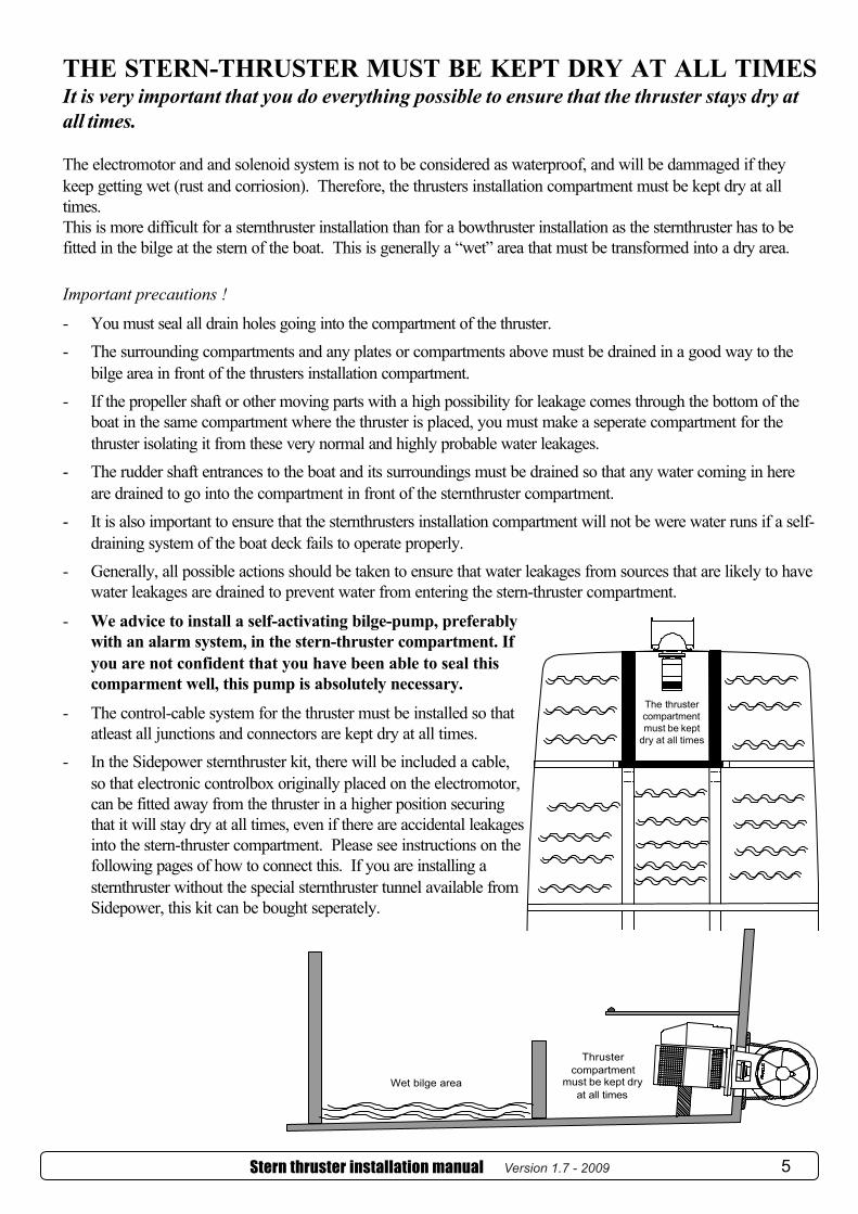
THE STERN-THRUSTER MUST BE KEPT DRY AT ALL TIMESIt is very important that you do everything possible to ensure that the thruster stays dry atall times.
The electromotor and and solenoid system is not to be considered as waterproof, and will be dammaged if theykeep getting wet (rust and corriosion). Therefore, the thrusters installation compartment must be kept dry at alltimes.This is more difficult for a sternthruster installation than for a bowthruster installation as the sternthruster has to befitted in the bilge at the stern of the boat. This is generally a “wet” area that must be transformed into a dry area.
Important precautions !
- You must seal all drain holes going into the compartment of the thruster.- The surrounding compartments and any plates or compartments above must be drained in a good way to the
bilge area in front of the thrusters installation compartment.- If the propeller shaft or other moving parts with a high possibility for leakage comes through the bottom of the
boat in the same compartment where the thruster is placed, you must make a seperate compartment for thethruster isolating it from these very normal and highly probable water leakages.
- The rudder shaft entrances to the boat and its surroundings must be drained so that any water coming in hereare drained to go into the compartment in front of the sternthruster compartment.
- It is also important to ensure that the sternthrusters installation compartment will not be were water runs if a self-draining system of the boat deck fails to operate properly.
- Generally, all possible actions should be taken to ensure that water leakages from sources that are likely to havewater leakages are drained to prevent water from entering the stern-thruster compartment.
- We advice to install a self-activating bilge-pump, preferablywith an alarm system, in the stern-thruster compartment. Ifyou are not confident that you have been able to seal thiscomparment well, this pump is absolutely necessary.
- The control-cable system for the thruster must be installed so thatatleast all junctions and connectors are kept dry at all times.
- In the Sidepower sternthruster kit, there will be included a cable,so that electronic controlbox originally placed on the electromotor,can be fitted away from the thruster in a higher position securingthat it will stay dry at all times, even if there are accidental leakagesinto the stern-thruster compartment. Please see instructions on thefollowing pages of how to connect this. If you are installing asternthruster without the special sternthruster tunnel available fromSidepower, this kit can be bought seperately.
The thrustercompartmentmust be kept
dry at all times
Thrustercompartment
must be kept dryat all times
Wet bilge area
Stern thruster installation manual Version 1.6 - 2005 5Version 1.7 - 2009
G
BC
DF
A
H
A
B
C
E
G
F
EB
A
H
F
D
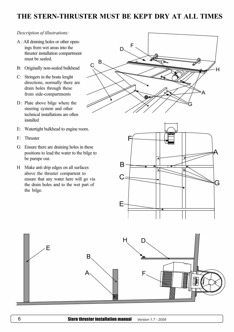
THE STERN-THRUSTER MUST BE KEPT DRY AT ALL TIMES
Description of illustrations:
A : All draining holes or other open-ings from wet areas into thethruster installation compartmentmust be sealed.
B: Originally non-sealed bulkhead
C: Stringers in the boats lenghtdirections, normally there aredrain holes through thesefrom side-compartments
D: Plate above bilge where thesteering system and othertechnical installations are ofteninstalled
E: Watertight bulkhead to engine room.
F: Thruster
G: Ensure there are draining holes in thesepositions to lead the water to the bilge tobe pumpe out.
H Make anti drip edges on all surfacesabove the thruster compartent toensure that any water here will go viathe drain holes and to the wet part ofthe bilge.
Stern thruster installation manual Version 1.6 - 20056 Version 1.7 - 2009
G
BC
DF
A
H
A
B
C
E
G
F
EB
A
H
F
D
THE STERN-THRUSTER MUST BE KEPT DRY AT ALL TIMES
Description of illustrations:
A : All draining holes or other open-ings from wet areas into thethruster installation compartmentmust be sealed.
B: Originally non-sealed bulkhead
C: Stringers in the boats lenghtdirections, normally there aredrain holes through thesefrom side-compartments
D: Plate above bilge where thesteering system and othertechnical installations are ofteninstalled
E: Watertight bulkhead to engine room.
F: Thruster
G: Ensure there are draining holes in thesepositions to lead the water to the bilge tobe pumpe out.
H Make anti drip edges on all surfacesabove the thruster compartent toensure that any water here will go viathe drain holes and to the wet part ofthe bilge.
Stern thruster installation manual Version 1.6 - 20056
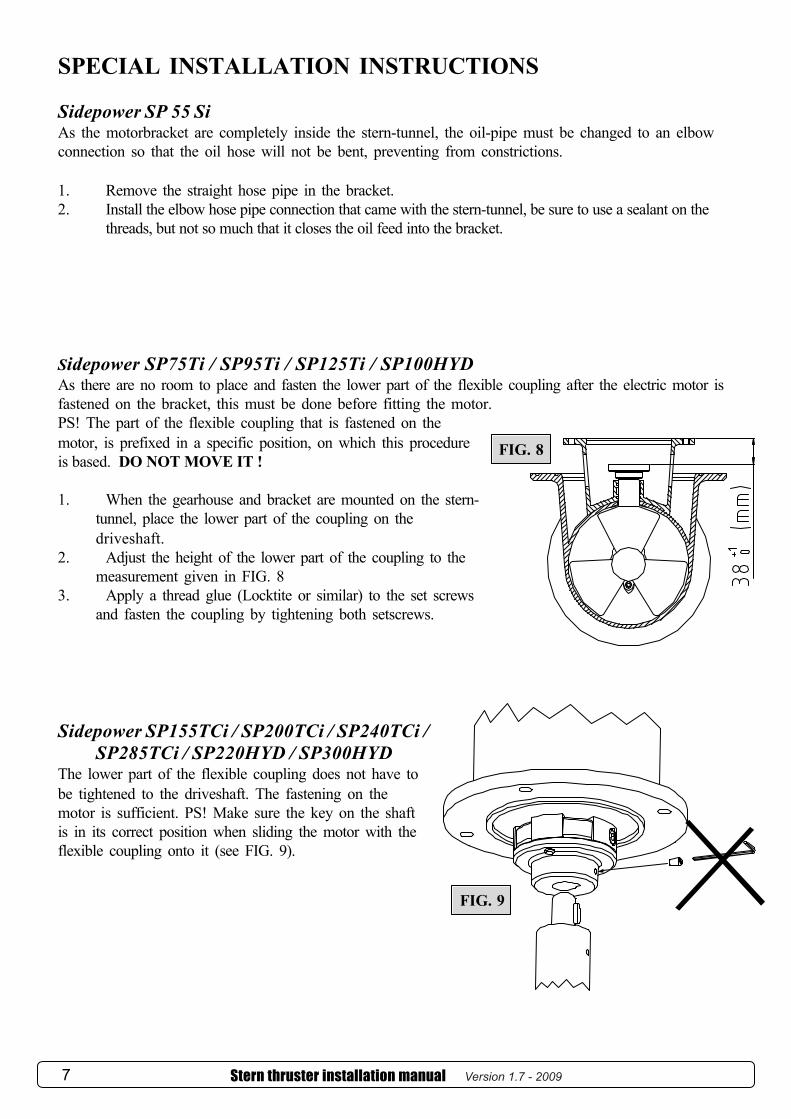
SPECIAL INSTALLATION INSTRUCTIONS
Sidepower SP 55 SiAs the motorbracket are completely inside the stern-tunnel, the oil-pipe must be changed to an elbowconnection so that the oil hose will not be bent, preventing from constrictions.
1. Remove the straight hose pipe in the bracket.2. Install the elbow hose pipe connection that came with the stern-tunnel, be sure to use a sealant on the
threads, but not so much that it closes the oil feed into the bracket.
Sidepower SP75Ti / SP95Ti / SP125Ti / SP100HYDAs there are no room to place and fasten the lower part of the flexible coupling after the electric motor isfastened on the bracket, this must be done before fitting the motor.PS! The part of the flexible coupling that is fastened on themotor, is prefixed in a specific position, on which this procedureis based. DO NOT MOVE IT !
1. When the gearhouse and bracket are mounted on the stern-tunnel, place the lower part of the coupling on thedriveshaft.
2. Adjust the height of the lower part of the coupling to themeasurement given in FIG. 8
3. Apply a thread glue (Locktite or similar) to the set screwsand fasten the coupling by tightening both setscrews.
Sidepower SP155TCi / SP200TCi / SP240TCi /SP285TCi / SP220HYD / SP300HYD
The lower part of the flexible coupling does not have tobe tightened to the driveshaft. The fastening on themotor is sufficient. PS! Make sure the key on the shaftis in its correct position when sliding the motor with theflexible coupling onto it (see FIG. 9).
FIG. 8
FIG. 9
Stern thruster installation manual Version 1.6 - 20057 Version 1.7 - 2009
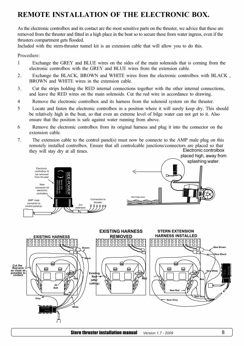
REMOTE INSTALLATION OF THE ELECTRONIC BOX.
As the electronic controlbox and its contact are the most sensitive parts on the thruster, we advice that these areremoved from the thruster and fitted in a high place in the boat so to secure these from water ingress, even if thethrusters compartment gets flooded.Included with the stern-thruster tunnel kit is an extension cable that will allow you to do this.
Procedure:1 Exchange the GREY and BLUE wires on the sides of the main solenoids that is coming from the
electronic controlbox with the GREY and BLUE wires from the extension cable.2. Exchange the BLACK, BROWN and WHITE wires from the electronic controlbox with BLACK ,
BROWN and WHITE wires in the extension cable.3. Cut the strips holding the RED internal connections together with the other internal connections,
and leave the RED wires on the main solenoids. Cut the red wire in accordance to drawing.4 Remove the electronic controlbox and its harness from the solenoid system on the thruster.5 Locate and fasten the electronic controlbox in a position where it will surely keep dry. This should
be relatively high in the boat, so that even an extreme level of bilge water can not get to it. Alsoensure that the position is safe against water running from above.
6 Remove the electronic controlbox from its original harness and plug it into the connector on theextension cable.
7. The extension cable to the control panel(s) must now be connecte to the AMP male plug on thisremotely installed controlbox. Ensure that all controlcable junctions/connectors are placed so thatthey will stay dry at all times.
Wet bilge area
SID
E-P
OW
ER
Electronic controlboxplaced high, away from
splashing water.
SID
E-PO
WE
R
Ref#61230
SleipnerMotorAS
N-1612Fredrikstad
Electronicinterfacefor
thrustermotorcontrols
Connectors to thruster
2mextension
Electroniccontrolbox to be removed from thruster
Newconnector for
electroniccontrolbox
AMP male connector to
control panel (s)
i
Stern thruster installation manual Version 1.6 - 2005 8
EXISTING HARNESS REMOVED
Red
ExistingRed
(aftercutting)
EXISTING HARNESS
SI DE- POWER
R ef # 6 123 0S le ipn er M ot or A SN - 1612 F re dri kst ad
Ele c tr o ni c in te r fa c e fo r th r u st er m ot o r co n tr o ls
Red
Black
Grey
Blue
Brown
Whitei
Cut theRed wire
as close aspossible to
contact
A2Bolt
New Grey
STERN EXTENSION HARNESS INSTALLED
Red
New Red
New Blue
New Black
SID
E-PO
WE
R
Re
f#6
1230
Sleipner
Motor
ASN-1
612Fred
rikstad
Ele
ctr
on
ici
nte
rfa
ce
fo
rth
ru
ste
rm
ot
or
con
tro
ls
New White
i
New Brown
ELECTRICAL INSTALLATION OF STERNTHRUSTER SYSTEMS
PS ! This is additional information especially for sternthruster installations, and the installationmanual for the thruster you are installing must be used complementary.
Stern thruster installation manual Version 1.6 - 2005 9
If a bow thruster is also installed, we strongly advice to use seperate battery banks for the twothrusters to avoid extreme voltage drop if both thrusters were to be used at the same time, and toensure maximum performance.
Battery banks must have common minus!Refer to the thruster manuals for advised battery capacity and cable sizes for each thruster.
If a single control panel other than Sidepower’s is to be used for both bow and stern thruster,be sure it has a single positive connection from only one of the two thrusters to avoid currentleakage between the two battery banks. If you are installing the standard Sidepower dualjoystick panel this is already taken care of.
Wiring diagram for installation with original Sidepower dual joystick panel.
SLEIPNER
SIDEPOWERTHRUSTERS
OFFON ON
BOW
STERNTo sternthruster
To bowthruster
grey
blue
blac
k
grey
bluered
ON / OFFSystemControl
light
Joystickfor stern-
thruster
Joystickfor bow-thruster
Positive lead fromsternthruster has been
removed in panel toavoid current leakage
betweenbattery banks if the
thrusters are poweredby different battery
banks.
Wiring diagram (simplified) for dual joystick panel
Visual connection diagram for dual joystick panel
When using the original Sidepower control cables just connect themto the corresponding joystick
There are no plus/positive power connected from the sternthruster
BOWSTERN
blac
k
Version 1.7 - 2009

ELECTRICAL INSTALLATION OF STERNTHRUSTER SYSTEMS
To use the Sidepower dual joystick panel with previously installed Sidepowerbowthruster with the older 3 lead electric system.- Please contact your distributor / dealer to purchase an upgrade kit to rebuild your existing bow-
thruster to the new 4 lead electric system. The wiring diagram on the previous page will then be thecorrect one for your complete system.
To use the Sidepower dual joystick panel with previously installed thruster ofother brand.- You should not use the Sidepower dual joystick panel as it is not designed to run other thruster
brands. It may be possible but you must consult a skilled electrician to ensure the compatibility.The panel can supply a maximum of 1Amp. in the standard configuaration and will therefore nor-mally not be able to directly drive main solenoids on a thruster.
- If you wish to use this panel to control another brand of bowthruster, a possible solution is torebuild the dual joystick panel, so that it for all practical purposes is transformed into two differentcontrols.This is done by removing all connections on the “bow-joystick” including the Sidepower connec-tor and the yellow cables between the two joysticks.You must then connect the black lead coming out of the ON/OFF system in the panel to aseperate ground/negative with the same ground potential the thrsuter because there are noground coming from the sternthruster.By this, the “bow-joystick” is totally seperated from the Sidepower panel and can be used andconnected as any other joystick or two way switch. Consult your other brand thruster manualfor correct connections. We advice to always fit an ON/OFF switch on the input lead to thejoystick so that it’s function can be de-activated when the thruster is not in use. See examplediagram below.
NB! Sleipner Motor claims no compatibility with other thruster brands and assumes noresponsibility for connection or usage with other thruster brands.
Stern thruster installation manual Version 1.6 - 200510
SLEIPNER
SIDEPOWERTHRUSTERS
OFFON ON
BOW
STERNTo Sidepowersternthruster
To other brandbowthruster
Visual connection diagram for rebuilt dual joystick panel
Control powerON / OFF
RH / LH run
LH / RH run
Remove the yellow jumper between BOW and STERN joysticks at the back of the panel.Move the two grey leads from the BOW joystick to the STERN joystick (a total of four grey leads at STERN joystick)
BOW
FUSE
Move the two blue leads from the BOW joystick to the STERN joystick (a total of four blue leads at STERN joystick)Contact marked with STERN is NOT in use!
INSTALLATION CHECKLIST
There is a sturdy additional support under the electric motor, taking the weight/ load of the electromotoraway from the stern-tunnel.
All bolts are securely tightened and sealant is applied as instructed All necessary actions have been taken to ensure that the thrusters installation compartment will stay dry at all
times. The electronic controlbox of the thruster have been remotely fitted in a high place where there are no chance
it will be submerged or splashed with water. All electrical wiring, cable sizes and battery capacity is according to the thruster installation manual. The unit has been moved by hand and found to run freely. The gear house, oil-hose and oiltank are filled with oil The gearoil tank is installed a minimum of 200mm above the waterline.
IMPORTANT USER ADVICE Never use the thruster if there are people or animals swimming in the area around the thruster. The
thruster propeller can cause serious injuries when it is running. WARNING ! Never store any items that can leak explosive gas in the same room where the sternthruster is
fitted. The thruster will create sparks that can cause an explosion if there are explosive gases present. When the boat is going backwards in a “dirty” harbour with lots of floating objects / debris, this can be
“collected” by the transom of the boat. These objects / debris can cause damage to the thruster ifsucked into the tunnel while the thruster are being operated. All the thrusters are built with safety devices(shearpin in the SP30Si / SP40Si / SP55Si & flexible couplings in the SP75Ti / SP95Ti / SP100HYD /SP125Ti / SP155TCi / SP200TCi / SP220HYD / SP240TCi / SP285TCi / SP300HYD / SP550HYDmodels) changeable from inside the boat, but damages can occur to other parts of the thruster in certain cases.
Always turn of the main power / disconnect the thruster from the batteries before touching any moving partsof the thruster inside or outside the boat.
If the thruster does not move the boat/does not give any thrust you must immediately stop trying to run it andturn off the main power switch until the reason for this is found and corrected.
This manual is in addition to the general thruster manual, so this must be read and understood also !
IMPORTANT NOTICESleipner Motor AS assumes no responsibility or liability for the installation of any components.
Skilled installers should be used, and there might be unforeseen factors that can make one or moreinstallation instructions wrong or not entirely correct for the boat in question. The installation re-sponsibility is thereby solely on the party that are actually performing the installation.
STERNTHRUSTER TUNNEL INSTALLED BY: ........................................................................................
DATE:............................. INSTALLED THRUSTER: ....................................................................
Stern thruster installation manual Version 1.6 - 2005 11Version 1.7 - 2009
ELECTRICAL INSTALLATION OF STERNTHRUSTER SYSTEMS
To use the Sidepower dual joystick panel with previously installed Sidepowerbowthruster with the older 3 lead electric system.- Please contact your distributor / dealer to purchase an upgrade kit to rebuild your existing bow-
thruster to the new 4 lead electric system. The wiring diagram on the previous page will then be thecorrect one for your complete system.
To use the Sidepower dual joystick panel with previously installed thruster ofother brand.- You should not use the Sidepower dual joystick panel as it is not designed to run other thruster
brands. It may be possible but you must consult a skilled electrician to ensure the compatibility.The panel can supply a maximum of 1Amp. in the standard configuaration and will therefore nor-mally not be able to directly drive main solenoids on a thruster.
- If you wish to use this panel to control another brand of bowthruster, a possible solution is torebuild the dual joystick panel, so that it for all practical purposes is transformed into two differentcontrols.This is done by removing all connections on the “bow-joystick” including the Sidepower connec-tor and the yellow cables between the two joysticks.You must then connect the black lead coming out of the ON/OFF system in the panel to aseperate ground/negative with the same ground potential the thrsuter because there are noground coming from the sternthruster.By this, the “bow-joystick” is totally seperated from the Sidepower panel and can be used andconnected as any other joystick or two way switch. Consult your other brand thruster manualfor correct connections. We advice to always fit an ON/OFF switch on the input lead to thejoystick so that it’s function can be de-activated when the thruster is not in use. See examplediagram below.
NB! Sleipner Motor claims no compatibility with other thruster brands and assumes noresponsibility for connection or usage with other thruster brands.
Stern thruster installation manual Version 1.6 - 200510
SLEIPNER
SIDEPOWERTHRUSTERS
OFFON ON
BOW
STERNTo Sidepowersternthruster
To other brandbowthruster
Visual connection diagram for rebuilt dual joystick panel
Control powerON / OFF
RH / LH run
LH / RH run
Remove the yellow jumper between BOW and STERN joysticks at the back of the panel.Move the two grey leads from the BOW joystick to the STERN joystick (a total of four grey leads at STERN joystick)
BOW
FUSE
Move the two blue leads from the BOW joystick to the STERN joystick (a total of four blue leads at STERN joystick)Contact marked with STERN is NOT in use!
INSTALLATION CHECKLIST
There is a sturdy additional support under the electric motor, taking the weight/ load of the electromotoraway from the stern-tunnel.
All bolts are securely tightened and sealant is applied as instructed All necessary actions have been taken to ensure that the thrusters installation compartment will stay dry at all
times. The electronic controlbox of the thruster have been remotely fitted in a high place where there are no chance
it will be submerged or splashed with water. All electrical wiring, cable sizes and battery capacity is according to the thruster installation manual. The unit has been moved by hand and found to run freely. The gear house, oil-hose and oiltank are filled with oil The gearoil tank is installed a minimum of 200mm above the waterline.
IMPORTANT USER ADVICE Never use the thruster if there are people or animals swimming in the area around the thruster. The
thruster propeller can cause serious injuries when it is running. WARNING ! Never store any items that can leak explosive gas in the same room where the sternthruster is
fitted. The thruster will create sparks that can cause an explosion if there are explosive gases present. When the boat is going backwards in a “dirty” harbour with lots of floating objects / debris, this can be
“collected” by the transom of the boat. These objects / debris can cause damage to the thruster ifsucked into the tunnel while the thruster are being operated. All the thrusters are built with safety devices(shearpin in the SP30Si / SP40Si / SP55Si & flexible couplings in the SP75Ti / SP95Ti / SP100HYD /SP125Ti / SP155TCi / SP200TCi / SP220HYD / SP240TCi / SP285TCi / SP300HYD / SP550HYDmodels) changeable from inside the boat, but damages can occur to other parts of the thruster in certain cases.
Always turn of the main power / disconnect the thruster from the batteries before touching any moving partsof the thruster inside or outside the boat.
If the thruster does not move the boat/does not give any thrust you must immediately stop trying to run it andturn off the main power switch until the reason for this is found and corrected.
This manual is in addition to the general thruster manual, so this must be read and understood also !
IMPORTANT NOTICESleipner Motor AS assumes no responsibility or liability for the installation of any components.
Skilled installers should be used, and there might be unforeseen factors that can make one or moreinstallation instructions wrong or not entirely correct for the boat in question. The installation re-sponsibility is thereby solely on the party that are actually performing the installation.
STERNTHRUSTER TUNNEL INSTALLED BY: ........................................................................................
DATE:............................. INSTALLED THRUSTER: ....................................................................
Stern thruster installation manual Version 1.6 - 2005 11
(shearpin in the SE 30 / SE 40 / SE 60 & flexible couplings in the SE 80 / SE 100 / SH 100 /SE 120 / SE 170 / SE 210 / SH 240 / SP240TCi / SP285TCi / SP300HYD / SH 420 / SH 550
Version 1.7 - 2009
ArgentinaTrimer SABuenos AiresTel: +54 11 4580 0444Fax: +54 11 4580 [email protected]
AustraliaAMI SalesFreemantle, WATel: +61 89 331 0000Fax: +61 89 314 [email protected]
AustriaG. Ascherl GmbHHard, BregenzTel: +43 5574 899000Fax: +43 5574 [email protected]
BeneluxASA Boot ElectroWatergangTel: +31 20 436 9100Fax: +31 20 436 9109www.asabootelectro [email protected]
BrazilElectra Service Ltda.GuarujaTel: +55 13 3354 3599Fax: +55 13 3354 [email protected]
BulgariaYachting BGBurgastel: +359 56 919090fax: +359 56 [email protected]
CanadaImtra CorporationNew Bedford, MATel: +1 508 995 7000Fax: +1 508 998 [email protected]
China/Hong KongStorm Force Marine Ltd.Wanchai, Hong KongTel: +852 2866 0114Fax: +852 2866 [email protected]
CroatiaYacht SupplierIciciTel: +385 51 704 500Fax: +385 51 704 [email protected]
DenmarkGertsen & Olufsen AS HørsholmTel: +45 4576 3600Fax: +45 4576 [email protected]
FinlandNautikulma OYTurkuTel: +358 2 2503 444Fax: +358 2 2518 470www.nautikulma.finautikulma@nautikulma .fi
FranceKent Marine EquipmentNantesTel: +33 240 921 584Fax: +33 240 921 [email protected]
GermanyJabsco GmbHNorderstedtTel: +49 40 535 373-0Fax: +49 40 535 373-11
GreeceAmaltheia MarineAthensTel: +30 210 2588 985Fax: +30 210 2588 986 [email protected]
IcelandMaras EHFReykjavikTel: +354 555 6444Fax: +354 565 7230www.maras .isgummi@maras .is
IndiaIndo Marine Engineering Co. Pvt. LtdPune, MaharashtraTel: +91 20 2712 3003Fax: +91 20 2712 [email protected]
IrelandSleipner Motor Ltd.South BrentTel: +44 1364 649 400Fax: +44 1364 649 [email protected]
IsraelAtlantis Marine Ltd.Tel AvivTel: +972 3 522 7978Fax: +972 3 523 [email protected]
SpainImnasa Marine ProductsGironaTel: +34 902 300214Fax: +34 902 [email protected]
SwedenSleipner ABStrömstadTel: +46 526 629 50Fax: +46 526 152 95www.sleipnerab.se
SwitzerlandMarine Parts Technics AGVolketswilTel: +41 1 997 40 90Fax: +41 1 997 40 [email protected]
SingaporeAlquest MarketingSingaporeTel: +65 6749 9359Fax: +65 6749 [email protected]
Singapore/Malaysia/Indonesia/Vietnam/PhillipinesIsland Marine Services Pte LtdSingaporeTel: +65 6795 2250Fax: +65 6795 [email protected]
TaiwanMercury Marine SupplyKaohsiungTel: +886 7 3317 293Fax: +886 7 3314 232
TurkeyDenpar Ltd.IstanbulTel: +90 212 346 1332Fax: +90 212 346 [email protected]
UKSleipner Motor Ltd.South BrentTel: +44 1364 649 400Fax: +44 1364 649 [email protected]
United Arab EmiratesTeignbridge Propellers & Marine Equipment Co. Ltd. DubaiTel: +971 4 324 0084Fax: +971 4 324 [email protected]
USAImtra CorporationNew Bedford, MATel: +1 508 995 7000Fax: +1 508 998 [email protected]
ItalySaim S.P.A. Assago-MilanTel: +39 02 488 531Fax: +39 02 488 254 5www.saim-group.com
JapanTurtle Marine Inc.NagasakiTel: +81 95 840 7977Fax: +81 95 840 [email protected]
MaltaS & D Yachts Ltd.CaliTel: +356 21 339 908Fax: +356 21 332 [email protected]
New ZealandAdvance Trident Ltd.AucklandTel: +64 9 845 5347Fax: +64 9 415 [email protected]
NorwaySleipner Motor ASFredrikstadTel: +47 69 30 00 60Fax: +47 69 30 00 [email protected]
PolandTaurus Sea Power SP. Z.O.OGdanskTel: +48 58 344 30 50Fax: +48 58 341 67 62
PortugalKrautli Portugal Lda.LisboaTel: +351 21 953 56 00Fax: +351 21 953 56 [email protected]
RussiaStandarteStarbeyevoTel: +7 495 575 67 23Fax: +7 495 575 39 [email protected]
South AfricaC-DynamicsCape Town Tel: +27 21 555 3232Fax: +27 21 555 [email protected]
CyprusOcean Marine Equipment LtdLimassolTel: +357 253 69731Fax: +357 253 [email protected]
Estonia/Latvia/LithuaniaMiltec Systems OÜTallinTel: +372 5013997Fax: +372 [email protected]
Sleipner Motor AS • P. O. Box 519, N-1612 Fredrikstad • Norway Tel: +47 69 30 00 60 • Fax: +47 69 30 00 70 • [email protected] • www.side-power.com
Service Centres