sidekick plasma cnc 2d cutting...
TRANSCRIPT

Sidekick Plasma CNC 2D Cutting Workflow
Computation & Construction Lab

Hypertherm Powermax 85 Plasma Arc Cutting System
Hardware
Air Filtration System + Remote
- Filters dust particles from CNC- Needs to remain ON at all times while working in the CNC room.
ShopSabre Sidekick Plasma CNC
- 2D cuts of steel- Turn the machine on once the files are ready to be cut.- Does not need to be turned ON/OFF between cuts unless manually handling CNC parts.

Over the Ear Hearing Protection
- It is recommended but not required to wear over the ear hearing protection while operating the plasma CNC.
Personal Protective Equipment
Shaded Safety Googles
- It is required to wear shaded eye protection while operating the plasma CNC.
Welding Cutains
- Move the welding curtains so that the CNC is not visable to the naked eye. It is dangerous to look directly at the plasma cutter while it is operating.

Cleaning
Mop
- Please clean any water from the bed or any drips from the steel. The mop is hanging to the left of the dry sink. Under the mop is a bucket with wheels for the water and cleaner, on the dry sink.
Ultra Strength Clorox Wipes
-Use Ultra Strength Clorox Wipes to clean any water or dirt off the Plasma CNC’s frame. These should be next to the Plasma CNC’s computer.
Panel Truck
-Put any extra steel on the red panel truck. Try not to leave steel on the bed of the plasma CNC unless you have permission from the CCL Associate. NEVER lift large sheets of steel alone!!

2D Cut Setup
EnRoute- Used to setup the toolpaths for the cut.- For 2D cutting.
CNC Setup
ShopSabre Plasma- Used to operate the plasma CNC.
Software
Design Setup
- Rhinoceros, AutoCAD, etc.- A range of softwares can be used to setup the initial design files to be cut.

Design Setup
Hints• This machine will NOT cut like a waterjet its
resolution is not excellent. Design with this in mind.
• Small geometries (anything under 1 inch) are difficult to cut on the plasma CNC.
• ALWAYS SelDup (select duplicate) in Rhinoceros prior to exporting your vectors. Cutting vectors twice will not go well on the plasma CNC.
• Be sure all vectors are planar.• Long cut vector should be oriented along
the y-axis. Materials are prone to warping in the x-axis.
Rhinoceros1. The 2D vectors needs to be exported as a
.dwg file.2. The geometry to be cut needs to fit within a
4 ft. x 8 ft. boundary (the size of the plasma CNC’s bed).
3. If the geometry does not fit within the 4 ft. x 8 ft. boundary or your steel is smaller, divide the geometry and export as separate files.
4. Small geometry (anything under an inch) should be saved on separate layers.

2D Cut Setup - EnRoute
Open EnRoute
1. Open EnRoute with icon on the desktop. Then close the window, “ Getting Started with EnRoute.”

2D Cut Setup - EnRouteNew File
3. Click ‘File’4. Click ‘New’
43

3D Mill Setup - VCarve ProJob Setup/Material Dimensions
1. Insert Width (x) and Height (y) of your material.2. Thickness (z): Insert the material your
thickness.3. Be sure to check that the “Surface is at the top
of the plate.”
2
3
1

2D Cutting - Enroute2D Profiles/Cut Out Tool Paths
1. Click “File.”2. Click “Import...” (FileName).dwg.3. Locate your file. Make sure that the Files of
Type is set to .dwg. 4. Once you find the file click open.
2
1
43
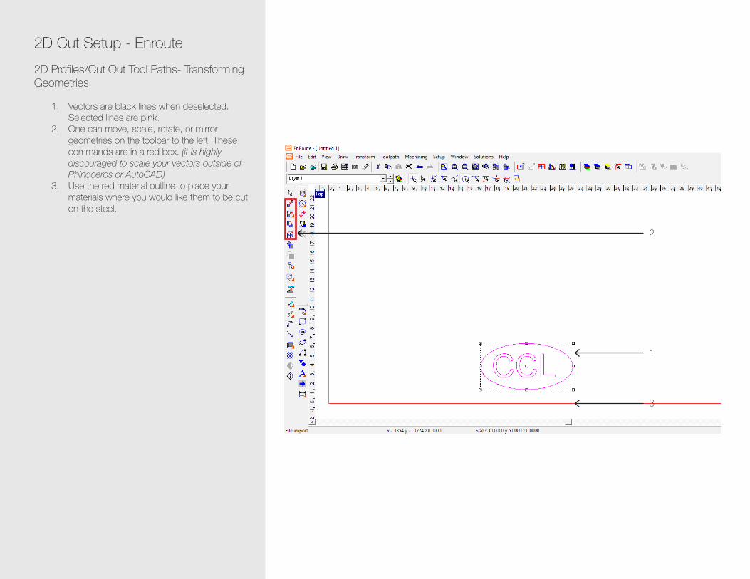
2D Cut Setup - Enroute2D Profiles/Cut Out Tool Paths- Transforming Geometries
1. Vectors are black lines when deselected. Selected lines are pink.
2. One can move, scale, rotate, or mirror geometries on the toolbar to the left. These commands are in a red box. (it is highly discouraged to scale your vectors outside of Rhinoceros or AutoCAD)
3. Use the red material outline to place your materials where you would like them to be cut on the steel.
2
1
3

2D Cut Setup - EnrouteMerging Vectors
1. Select Vectors. When selected Vectors will be pink.
2. Click “Transform”3. “Merge Selection...”4. Merge Tolerance should remain at 0.010. 5. Click “OK.” The exterior vectors will be blue
and the interior will be red.
2
1
5
3
4

2D Cut Setup - EnroutePreferences- Start Points
1. Press “F10” on the keyboard to open Preferences.
2. Click “Start Points”3. Check “Longest Segment”4. Check “Segment Midpoint”5. Click “OK”
2
43
5
1
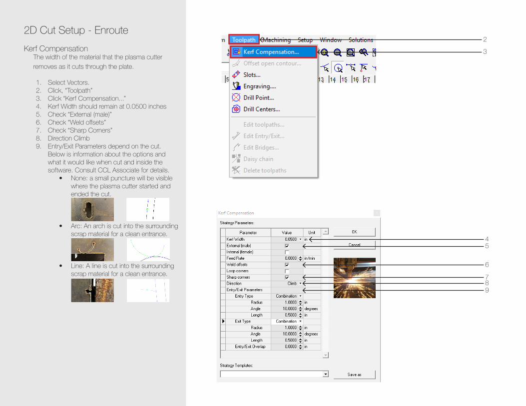
2D Cut Setup - EnrouteKerf Compensation
The width of the material that the plasma cutter removes as it cuts through the plate.
1. Select Vectors.2. Click, “Toolpath”3. Click “Kerf Compensation...” 4. Kerf Width should remain at 0.0500 inches5. Check “External (male)”6. Check “Weld offsets”7. Check “Sharp Corners”8. Direction Climb9. Entry/Exit Parameters depend on the cut.
Below is information about the options and what it would like when cut and inside the software. Consult CCL Associate for details.
• None: a small puncture will be visible where the plasma cutter started and ended the cut.
• Arc: An arch is cut into the surrounding scrap material for a clean entrance.
• Line: A line is cut into the surrounding scrap material for a clean entrance.
3
45
2
6
789

2D Cut Setup - EnrouteEntry + Exit Points
It is important to figure out where your entry and exit points are located before you cut. You may need to move them if they are in a bad location or if they arecutting into a part you are cutting.
1. Click “Toolpath”2. Click “Edit Entry/Exit”3. Click the green crosshairs to move the entry/
exit points.
2
1
3

2D Cut Setup - EnrouteExporting
1. Click “Machining”2. Click “Output”3. Click “To File”4. Save your file to the Desktop or your course’s
folder. Type a file name and click “Save”
2
1
3

CNC SetupTurning on the Plasma CNC + Preparing to Cut
1. Switch the power button to up on the left side of the CNC to turn the machine on.
2. Move the black and red handle up to turn the power to “on.” Off is down/black (2A). On is red/up (2B).
3. Check that the air that the air is switched to on. When it is on the lever is horizontal. When it is off the lever is vertical. This switch is located between the Stinger 1 and the ShopSabre Pro 510 CNC.
4. Prior to putting your material onto the bed of the plasma CNC be sure that there is nothing on the any of the metal panels that hold the material. Be sure that none of the panels are sticking up further than the others. It does not hurt to gently tap each panel with a mallet to ensure they are in the proper position. Store your materials on the red panel truck to the right of the Plasma CNC (4A). Move your material onto the plasma CNC. ALWAYS have someone help you when moving large, heavy pieces of steel! Align the steel to the corner of the bed with the ShopSabre logo and warning stickers/front left corner (4B).
5. Make sure that the torch is at its lowest point on the magnet (5A) and that it is level (5B).
6. The water in the bed of the plasma CNC should be a 1/8-1/4 inch below the material (6A). If it needs to be filled use the hose under the Plasma CNC. This hose will has an adapter so it can attach to the faucet (6B). Be sure that the hose is in the bed of the Plasma CNC prior to turning on the water.
OFF
ON
ON
1 2A
3 4A
5A 6B5B 6A
2B
4B

ShopSabre ControllerCutting with the Plasma CNC
In order for the ShopSabre Controller to work the Plasma CNC must be turned on.
1. Open the ShopSabre Controller labeled ShopSabre Plasma on the desktop icon.
2. Click “Home.” In the right upper corner of the controller here will be an XYZ position. When this is red the CNC is unsure of its position and needs to be homed. As the machine homes each axis will change to white. Once each is white it is finished homing.
3. By using the arrows in the central portion of the controller screen find the XY Zero. Once you have moved the tourch to this point click XY Zero. You can change the movement speed to Slow, Medium, or Fast.
2
2
3

Cutting with the Plasma CNC Continued
4. Make sure that the material you are using is selected in the drop down options in the middle of the controller. If you are not using on of the configured materials consult the CCL Associate and the Using Materials without Configuration Settings and Setting Up Material Configuration.
5. Click “File” > “Open” > Find your file.6. Click “File” > “View.” This will render a your file
in green vectors. The red outline is the bed of the CNC. The dashed lines are travel. The red point is the plasma tourch. If you are cutting on a piece of steel that already has a few cuts you can move the tourch using the central arrows to double check that you will be cutting in an area that has not already been cut.
7. ALWAYS DOUBLE CHECK THE FOLLOWING PRIOR TO STARTING A JOB
• Double check that the tourch is level• The welding curtains are surrounding the
Plasma CNC.• No one is inside the welding curtains.• Everyone watching the job has their
shaded safety googles on.8. Once you feel comfortable that all of this
section has been completed properly you can press enter to start the job.
9. YOU MUST REMAIN WITH YOUR JOB AT ALL TIMES! Stay vigilant! The torch can be knocked off level. If it gets off level be sure to pause the job immediately. Then realign the torch and unpause the job. If you end up aborting a print follow the directings from the section Restarting a Job.
4 5
6 7

ShopSabre ControllerFeatures of the ShopSabre Controller
1. Start Button- Starts and runs all programs.2. Restart Button- Reruns a program exactly
where it was stopped3. Simulation Button- Tells you what and where
an error is in the G-Code.4. Stop Button-Abort the CNC job5. Pause- Pause the CNC job6. Edit Pad- Allows you to edit the G-Code7. View Button- Will run the program in simulation
mode and display part on grid.8. Will manually fire the torch outside of the
program, and will depress while a program fires the torch.
9. Configuration screen- where you will input your torch settings.
1 2 3 4 5 6 7 89

ShopSabre ControllerUsing Materials without Configuration Settings
1. Go into the Config settings in the ShopSabre CNC Controller
2. Find the material that is closest to the material you are trying to cut ie. 10 gauge would be the best reference for 11 gauge steel.
3. Set the Torch Distance to 2.000 inches4. Disable the cutting height.5. Click “Save”
1
3
4
2
5

6. Set an XY Zero using the ShopSabre Controller. The file will be a 6 inch line.
7. File “Open” > “This PC” > “Local Disk (C:)” > “WinCNCPlasma” > “Test files” > “line.tap”
8. Run the file. As the torch cuts watch the arc voltage. The highest value should be the target voltage.
9. Open the Config settings and change the target voltage to the arc voltage. Enable Cutting Height. Click “Save.”
10. Run another line test and watch the z axis to make sure that is does not fluctuatate up and down too far (>1/8”).
11. By increasing the target voltage one can raise the height of the torch. This can be altered in real time with the addition and subraction keys on the right portion of the keyboard.
7
8
10

ShopSabre ControllerRestarting a Job
If a job is aborted it you can restart where it was aborted by following the steps below.
1. Click the Restart icon.2. Select the file from the Recent files list.3. Type the line number that the job was aborted.4. Click, ‘OK’
12
3
3

Plasma CNC MaintenanceBe sure that the Plasma CNC and torch are powered off for the following maintenance. The bold steps should be preformed immediately after using the Plasma CNC.
1. Clean the torch body (once a month, depends on use)
A. Remove the screw holding the cables from the torch with a 5/32 Allen wrench.
B. Store parts in a cup or small container.C. Push down lever and unplug the
cablesD. Disconnect torch from magnet.E. Unscrew the torch shield. F. Clean the torch shield with a damp
Scotch-Brite pad. This should be done every time the CNC is used!
G. Remove the retaining cap by unscrewing it.
H. Inspect and make sure the bleed holes are clean.
I. Remove the nozzle. It should be sure that the hole is round. If it is not round it needs to be replace because it will not cut accurately. Check inside to see if there is any damage and if the hole is round.
J. (Top Image) Remove electrode. (Bottom Image) Inspect the electrode. The pit should not be greater than 1/16” deep. If greater, like the one to left in the image, it will need to be replaced with a new electrode, the one to the right in the image.
K. Insert electrode.L. Place the nozzle over the electrode.

M. Replace the retaining cap.N. Replace the torch shieldO. Place torch back on magnetP. Level the torchQ. Connect cablesR. Attach the screw holding the cables to
the torch with a 5/32 Allen wrench.
2. Clean torch leads (every time the CNC is uses)
Wipe down or blow off the entire length of the torch leads to remove accumulated metal dust and dirt. Metal dust can cause dissipation of the high voltage needed to start the plasma arc. Check for kinked or worn hoses, exposed wires, cracked fittings, or other damage. Check high-frequency shielding for proper connection to earth ground. Wipe the frame after use to get rid of any water or dirt.
3. Water Quality (once a week)Check the water with a pH strip it should be 9 pH. If the water in the table is heavily contaminated with slag and metal dust, it can cause hard-starting of the plasma torch. It may also cause rust accumulation on the cut pieces. The Plasma Defense is added to the water to prevent corrosion of the water table and the work piece. It will inhibit bacteria growth, maintain water stability and prevent odors. The use directions can be found on its 5-gallon bucket along with more information about the product.