siemens automotive stamping solutions · automotive stamping solutions siemens automotive stamping...
TRANSCRIPT

siemens.com/plm
Siemens PLM Software
Automotive Stamping SolutionsCombine PLM software with Siemens production equipment to transform design, manufacture and production efficiency

Automotive stamping dies and press lines are high-cost, long lead-time investments. To maximize return on investment (ROI), it’s important to streamline development and commissioning of new lines, while flexibly adapting existing lines to new designs.
Your fully functioning press line’s ROI depends on the time required for die engi-neering, optimization, building and setup as well as press line commissioning and produc-tion rampup. ROI also depends on the press line’s throughput while running in produc-tion. In addition, because of the complex nature of today’s press lines, the success of your stamping process is never fully deter-mined until the commissioning process is complete.
As you plan, design, validate, manufacture and commission your press line equipment, you can leverage Siemens PLM Software’s complete suite of CAD, CAM, CAE and PLM solutions and Siemens production equipment (which includes controllers and drivers) to:
• Reduce the time needed for production rampup
• Achieve greater throughput without sacrificing quality
• Meet material waste reduction objectives
Increase return on stamping die and press line investments
PROVEN VALUE
• Increase the stroke rate by 10 percent
• Reduce try-out time by 70 percent
• Reduce tooling design cost by 50 percent
• Reduce die design errors by 90 percent
Achievable improvements as reported by customers.
2

Introducing Siemens automotive stamping solutions
Siemens automotive stamping solutions are used by leading companies to optimize operational efficiency and reduce time, cost and errors in design, planning and production of sheet metal parts and dies.
Best-in-class software applications and production equipmentSiemens PLM Software provides a comprehensive and integrated founda-tion of CAD/CAM/CAE/PLM applications for planning, designing, simulating and manufacturing complete stamping die press lines.
Siemens SIMOTION controller and drives deliver stamping line equipment that facilitates production reliability, intelligent energy management and maintenance cost reduction.
Complete and integrated solution set from planning to commissioningThe stamping process plays a major role in determining the efficiency of auto-motive body part production. Ever-increasing requirements for shorter production times are met by leveraging Siemens PLM Software’s specialized planning, design, manufac-turing and simulation solutions.
Process planning and data managementStamping process development is a highly collaborative activity requiring effective communication across mul-tiple disciplines including product design, tooling design, manufacturing engineering, industrial operations and production teams. Siemens PLM Software solutions provide process planning, data management and con-figuration control, as well as flexible reporting, to ensure the availability of the right data, when and where it’s needed.
Dieplanning
Partdesign
Diefeasability
Die designand validation
Diemanufacturing
Diemanufacturing
Partproduction
Try-out
Productdata
Dielayout
Die facedesign Inspection
Press lineoptimization
Primarytry-out
2Dmachining
Die facemachining
Secondarytry-out
Formabilityanalysis
NCpreparation
Partproduction
DFManalysis
Part transferoptimization
Springbackmodeling
Partdesign
Springbackanalysis
Die structureanalysis
Die structuredesign Design
correction
Die kinematicsvalidation
3
Business value
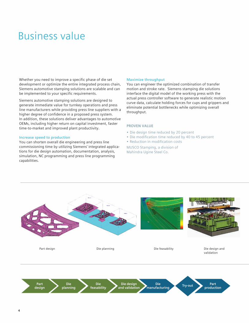
Whether you need to improve a specific phase of die set development or optimize the entire integrated process chain, Siemens automotive stamping solutions are scalable and can be implemented to your specific requirements.
Siemens automotive stamping solutions are designed to generate immediate value for turnkey operations and press line manufacturers while providing press line suppliers with a higher degree of confidence in a proposed press system. In addition, these solutions deliver advantages to automotive OEMs, including higher return on capital investment, faster time-to-market and improved plant productivity.
Increase speed to productionYou can shorten overall die engineering and press line commissioning time by utilizing Siemens’ integrated applica-tions for die design automation, documentation, analysis, simulation, NC programming and press line programming capabilities.
Maximize throughputYou can engineer the optimized combination of transfer motion and stroke rate. Siemens stamping die solutions interface the digital model of the working press with the actual press controller software to generate realistic motion curve data, calculate holding forces for cups and grippers and eliminate potential bottlenecks while optimizing overall throughput.
PROVEN VALUE
• Die design time reduced by 20 percent• Die modification time reduced by 40 to 45 percent• Reduction in modification costsMUSCO Stamping, a division of Mahindra Ugine Steel Co.
Part design Die planning Die feasability Die design and validation
Dieplanning
Partdesign
Diefeasability
Die designand validation
Diemanufacturing
Partproduction
Try-out
4
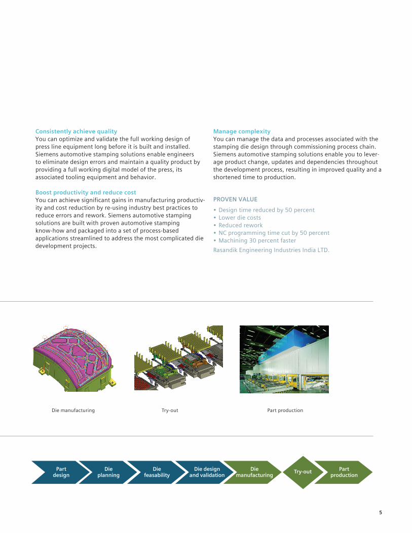
Consistently achieve qualityYou can optimize and validate the full working design of press line equipment long before it is built and installed. Siemens automotive stamping solutions enable engineers to eliminate design errors and maintain a quality product by providing a full working digital model of the press, its associated tooling equipment and behavior.
Boost productivity and reduce costYou can achieve significant gains in manufacturing productiv-ity and cost reduction by re-using industry best practices to reduce errors and rework. Siemens automotive stamping solutions are built with proven automotive stamping know-how and packaged into a set of process-based applications streamlined to address the most complicated die development projects.
Manage complexityYou can manage the data and processes associated with the stamping die design through commissioning process chain. Siemens automotive stamping solutions enable you to lever-age product change, updates and dependencies throughout the development process, resulting in improved quality and a shortened time to production.
PROVEN VALUE
• Design time reduced by 50 percent• Lower die costs• Reduced rework• NC programming time cut by 50 percent• Machining 30 percent fasterRasandik Engineering Industries India LTD.
Dieplanning
Partdesign
Diefeasability
Die designand validation
Diemanufacturing
Partproduction
Try-out
Die manufacturing Try-out Part production
5

Part design
A vehicle’s body design and individual body panel parts not only influence the vehicle’s appearance, but also affect its overall safety, weight, and performance. Inner and outer body panel part models are the manufacturing team’s primary input for initiating the stamping die development process, which requires a long lead-time. Since body design is crucial to most vehicles’ marketing success, it is not uncommon for body panel designs to change often and late in the vehicle develop-ment cycle due to evolving design, engineering and manufacturing requirements.
Siemens PLM Software provides the design and modeling tools for quickly and effectively generating and editing complicated automotive body panel parts, and tools for working with data imported from other CAD systems.
Quickly model accurate automotive sheet metal partsSupport of automotive workflows within a single system enables maximum efficiency and creative flexibility.
Easily update models to design changesDesign changes happen in real time by direct manipulation of the model, without needing to understand the history of how the model was created.
Document designs for proper manufacturingPMI (product manufacturing information) can be directly specified on the 3D model and used to create accurate, fully associative detailed drawings. PMI can also be made accessible to the extended enterprise/supply chain for manufacturing automation.
Advantages• Easily work with data from any CAD system by using
data quality checks, geometry healing, and an extensive set of data translators
• Reduce design time by applying specialized sheet metal features and synchronous technology for rapid model edits
• Ensure proper manufacturability upfront during the design phase with comprehensive checks for draw, trim, pierce, and flange criteria
• Automate checking of part designs for conformance to corporate standards
Dieplanning
Partdesign
Diefeasability
Die designand validation
Diemanufacturing
Partproduction
Try-out
6

Die planning
The ROI of a press line is established during the early planning phases when die lineup and production throughput targets are determined. Die lineup spacing, opening height, and material travel speed are all critical factors that directly impact the overall efficiency of the working press line and can influence the frequency of maintenance interruptions and downtime.
Siemens PLM Software provides the complete set of tools for defining the die operation lineup (DOL) and optimizing line efficiency to help ensure planned production targets are achieved.
Rapidly layout the die lineup You can generate process models for each station of the press line, as well as determine which areas of the part should be formed, flanged and trimmed. In addition, you can determine the location of the holes and tip the part into the die position.
Optimization of die lineup efficiencyYou can leverage the PLM solution to calculate and simulate part motion from de-stacking through removal. You can also calculate part transfer speeds and application, as well as identify and correct handling issues caused by part transfer speed and acceleration.
Part deflection/behavior simulationThe PLM die planning solution enables you to simulate material deflection of the part under transfer conditions as you plan the die line’s operational parameters. It also optimizes positioning of holding devices like grippers, shovels and suction cups. You can define clearance zones that account for part deflection under production conditions to aid die design and transfer programming.
Advantages• Leverage manufacturing process rules that enable you
to make better manufacturing throughput decisions• Optimize the stamping position of parts using dynamic
draft and depth analysis• Improve collision detection accuracy by including
workpiece and holding device deformation in part transfer clearance analyses
• Validate suction cup and gripper holding force requirements per part transfer speed and acceleration
Die operation layout (DOL)
Material deflection analysis
Transfer motion analysis
7
Die face design and feasibility
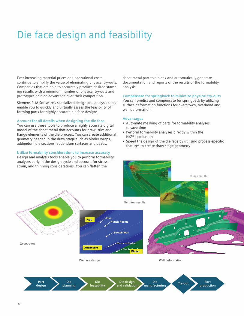
Ever increasing material prices and operational costs continue to amplify the value of eliminating physical try-outs. Companies that are able to accurately produce desired stamp-ing results with a minimum number of physical try-outs and prototypes gain an advantage over their competition.
Siemens PLM Software’s specialized design and analysis tools enable you to quickly and virtually assess the feasibility of forming parts for highly accurate die face designs.
Account for all details when designing the die faceYou can use these tools to produce a highly accurate digital model of the sheet metal that accounts for draw, trim and flange elements of the die process. You can create additional geometry needed in the draw stage such as binder wraps, addendum die sections, addendum surfaces and beads.
Utilize formability considerations to increase accuracy Design and analysis tools enable you to perform formability analyses early in the design cycle and account for stress, strain, and thinning considerations. You can flatten the
sheet metal part to a blank and automatically generate documentation and reports of the results of the formability analysis.
Compensate for springback to minimize physical try-outsYou can predict and compensate for springback by utilizing surface deformation functions for overcrown, overbend and wall deformation.
Advantages• Automate meshing of parts for formability analyses
to save time• Perform formability analyses directly within the
NX™ application• Speed the design of the die face by utilizing process-specific
features to create draw stage geometry
Dieplanning
Partdesign
Diefeasability
Die designand validation
Diemanufacturing
Partproduction
Try-out
Overcrown
Die face design Wall deformation
Stress results
Thinning results
8
Die structure design and validation
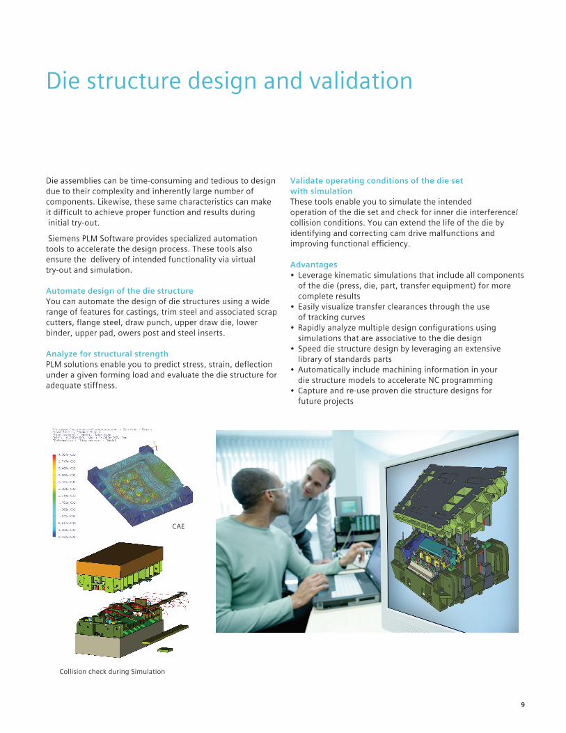
Die assemblies can be time-consuming and tedious to design due to their complexity and inherently large number of components. Likewise, these same characteristics can make it difficult to achieve proper function and results during initial try-out.
Siemens PLM Software provides specialized automation tools to accelerate the design process. These tools also ensure the delivery of intended functionality via virtual try-out and simulation.
Automate design of the die structureYou can automate the design of die structures using a wide range of features for castings, trim steel and associated scrap cutters, flange steel, draw punch, upper draw die, lower binder, upper pad, owers post and steel inserts.
Analyze for structural strengthPLM solutions enable you to predict stress, strain, deflection under a given forming load and evaluate the die structure for adequate stiffness.
Validate operating conditions of the die set with simulationThese tools enable you to simulate the intended operation of the die set and check for inner die interference/collision conditions. You can extend the life of the die by identifying and correcting cam drive malfunctions and improving functional efficiency.
Advantages• Leverage kinematic simulations that include all components
of the die (press, die, part, transfer equipment) for more complete results
• Easily visualize transfer clearances through the use of tracking curves
• Rapidly analyze multiple design configurations using simulations that are associative to the die design
• Speed die structure design by leveraging an extensive library of standards parts
• Automatically include machining information in your die structure models to accelerate NC programming
• Capture and re-use proven die structure designs for future projects
Collision check during Simulation
Stress results
CAE
9

Die manufacturing
Automotive industry expectations for delivery time, price, and quality continue to become increasingly demanding. Likewise, machine tools, materials and parts are becoming more complex. These factors can negatively impact manufac-turing efficiency. As a result, they drive manufacturers to find new manufacturing approaches for optimizing machin-ing and eliminating waste.
Siemens PLM Software provides NC programming with advanced capabilities, programming automation, and produc-tion ready output to help optimize your machining operations by reducing machining time, eliminating errors and improv-ing part quality.
Quickly prepare CAD models for NC programmingAn extensive set of modeling capabilities is available to NC programmers for model preparation including hole fill, radius reduction, surface extension and surface offsetting.
Advanced programming capabilities for die face machiningA wide range of high-speed machining (HSM) strategies deliver efficient hard milling. The machining data library provides proven data for optimum machining performance. Synchronized point distribution delivers superior surface finish. NC programs are associatively linked to design data for rapid updates to changes.
Automate programming of die structure componentsYou can save time by using feature-based machining (FBM) capabilities to automatically recognize features and assign the proper machining operations. You can also increase efficiency by capturing and re-using your proven machining processes.
Simulate machining to eliminate errors before productionYou can verify machining operations by using highly accurate and digital machine tool models before heading into produc-tion to save time, material and machine tool resources.
Advantages• Employ proven machining strategies to reduce machining
time by as much as 50 percent• Minimize the number of prove-outs with highly accurate
machining simulations• Achieve faster repeatable NC programming, requiring
less expertise• Use programming automation to cut NC programming time• Use the same system for CAD/CAM to eliminate data
translation
Dieplanning
Partdesign
Diefeasability
Die designand validation
Diemanufacturing
Partproduction
Try-out
Hole fill
10

Try-out and optimization
Regardless whether you’re commissioning a new line or modifying an existing line, you need to meet your start-of-production deadlines, as well as your production throughput and quality targets. To achieve these objectives, you must be able to quickly respond when unacceptable try-out results occur, which requires you to have intimate knowledge of the entire press.
Siemens PLM Software’s reverse engineering toolset enables you to support the activities associated with modifying, maintaining and repairing your press line equipment by ensuring that the parts you manufacture are produced to the desired quality. In addition, you can employ Siemens PLM Software’s press line simulation capabilities prior to commis-sioning the press line to ensure that it will run error-free at peak performance.
Rapidly correct the die face based on try-out resultsYou can directly machine corrections from the polygon data when parts are small and lack details. Powerful modeling capabilities are available to enable you to rapidly generate surfaces from polygons when scan data is insufficient for machining.
Validate kinematics by simulating actual press line operating conditionsYou can simulate the intended operation of the press-line, individual press elements and inter-press handling equipment to check for interference/collision conditions. You can verify part behavior with dynamic loading during transfers. Kinematic simulations can include cross bar and tri-axis press types.
Optimize throughputYou can optimize throughput by simulating the entire press line. You can program the press directly from optimized simulation parameters based on the job and press parameters.
Advantages• Ensure stamping process sustainability by feeding back
data from the physical process to the virtual planning and design environment
• Reduce rampup time by optimizing stroke rate and material flow in the virtual try-out phase
• Use the virtual process planning phase to eliminate iterations and reduce physical try-out time on the shop floor
• Use job-specific press setup information and try-out results to reduce the overall time to production
11

Commissioning and part production
Die duplication and repairWhen minor changes to the production part or die repairs are needed, dies can be easily reproduced and updated. The die faces can be machined directly from scanned polygon data or from surfaces developed from scanned data. Specialist part-ner TTL provides NX CAM based adaptive machining for die face scanning and remachining.
Virtually commission the pressYou can simulate the setup procedure and die change process to ensure a collision-free setup environment.
Simulate part productionYou can execute a virtual production run using the actual controller program data, complete the press model including the press line, die sets and part stages and transfer to verify a properly functioning production environment.
Directly transfer program data to the shop floorYou can transfer validated programming parameters and settings from the simulation environment directly to the actual press line controller.
Advantages• Improve confidence while reducing time to production• Rapidly perform tool changes• Quickly adapt dies to design changes• Reduce downtime due to repairs and maintenance
Dieplanning
Partdesign
Diefeasability
Die designand validation
Diemanufacturing
Partproduction
Try-out
Die duplication process
Data collection Data cleaning Surfacing Machining
12

Simulation assisted optimization of motion curves
New advances in press line technology at the servo drive level enable you to flexibly control slide motion. Servo drives can deliver up to a 30 percent improvement in press throughput over conventional mechanical and hydraulic presses. But in order to obtain these benefits you need to precisely synchronize the motion of the slide and transfer system with the motion of the draw and stamping dies.
This level of motion optimization requires a sophisticated software environment that can drive a complete simulation of a virtual press model by leveraging the actual press controller program. Siemens PLM Software’s press line simulation application can accomplish this by reading and simulating actual press motion curves from SIMOTION, Siemens’ motion control system for electronically-driven press lines.
In addition to improving production throughput, the direct integration of the press line simulation application and the SIMOTION controller facilitates:
• Virtual functional verification of the working press system
• Improved energy utilization• Direct data exchange between the simulation software and
the press line controller • Press line programming based on optimized control
programs from the simulation output
13

Manufacturing process management
In today’s highly competitive automotive marketplace, industry-leading companies must effectively leverage the combined strengths of their engineering and manufacturing teams to deliver world-class products.
Teamcenter® software’s capabilities for manufacturing process management enables your product development and manufacturing operations to collaborate and become more efficient across aging manufacturing data and process, resource, and plant knowledge in the same PLM environment that you use for product development. Teamcenter allows you to streamline new product development and launch processes to optimize your cost structures and satisfy estab-lished production goals.
Single source of manufacturing knowledge: Teamcenter provides a single source of manufacturing knowledge that enables you to rationalize and leverage your engineering assets and synchronize your manufacturing deliverables in a parallel workflow.
Advanced BOM/BOP management: Teamcenter associatively relates essential bill of materials (BOM) information with your manufacturing bill of process (BOP). This ensures you are using the right product configurations in the right manufacturing context.
Production and shop floor management: Teamcenter tight integration with Tecnomatix® software enables your PLM environment to leverage manufacturing and production data from a complete suite of digital manufacturing solutions. Teamcenter open service oriented architecture (SOA) inte-grates CAM, ERP and MES systems-of-choice into your PLM environments.
Teamcenter provides standardized process templates and automated work instructions to simplify the transfer of planning information to your shop floor.
Manufacturing resource visibility: With Teamcenter, you can classify multiple manufacturing resources (tooling, fixtures, machinery and robots) and establish best practice processes to manage their use. Integrated tools enable you to mock up, visualize, analyze and optimize plan layout and material flow.
Advantages• Enable product and manufacturing teams to work in
parallel, reducing planning time by 40 to 50 percent• Increase productivity and support lean manufacturing and
design-for-manufacturing initiatives• Synchronize BOM and BOP activities to enable teams to
better understand product change
14

Siemens automotive stamping solutions
Dieplanning
Partdesign
Diefeasability
Die designand validation
Diemanufacturing
Diemanufacturing
Partproduction
Try-out
Productdata
Dielayout
Die facedesign Inspection
Press lineoptimization
Primarytry-out
2Dmachining
Die facemachining
Secondarytry-out
Formabilityanalysis
NCpreparation
Partproduction
DFManalysis
Part transferoptimization
Springbackmodeling
Partdesign
Springbackanalysis
Die structureanalysis
Die structuredesign Design
correction
Die kinematicsvalidation
NX Software’s Body Design: Provides automotive designers and engineers with a tailored set of features, assistants and advisors for quick and simple creation and validation of body-in-white sheet metal parts.
NX Die Engineering: Provides a process-specific toolset for laying out and planning the tasks to be performed in each station of the die lineup. Also includes specialized tools to assist in accelerating the design of die faces.
NX OneStep Formability: Provides a FEM-based sheet metal unforming, flattening and formability analysis solution for die makers.
NX Global Shaping: Includes a set of specialized functions to deform sheet metal parts and compensate for springback.
NX Die Structure Design: Provides a comprehensive toolset for designing complete die structure solid model assemblies that includes standard components for piercing equipment, pressure systems and air cylinders, as well as specialized features for draw, trim and flange dies.
NX Die Validation: Enables die designers to simulate and check the function of die assemblies with respect to collision-free operation within the press.
NX Machining: Enables you to accelerate NC programming and improve productivity for a variety of typical manufactur-ing challenges, from basic machining to complex, multiple-axis and multi-function machining, as well as for mold and die manufacturing.
Tecnomatix Press Line Simulation: Includes a comprehensive set of process line programming, simulation and analysis tools that enable you to digitally prepare and optimize key elements in a press line job early in the planning phase.
Tecnomatix Part Planner: Enables manufacturing engineers, NC programmers, tool designers and managers to work in a managed environment with build-in applications for creating outline process plans, managing and associating tools and creating reports targeted at part manufacturing.
Resource Manager: Includes Teamcenter solution for managing a wide range of manufacturing resource data, including everything from cutting tools, machine tools and fixtures to robots, welding guns and manufacturing process templates.
Manufacturing Process Management: Includes Teamcenter solution for enabling design and manufacturing teams to formally collaborate in a digital environment with full associativity between product, process, resource and plant information.
SIMOTION control system and SimoPress Servo drives: Provides an energy efficient, fast and flexible servo press system for powering the most demanding press lines. Retrofits to existing hydraulic and mechanical presses to further enhance production performance.
15

About Siemens PLM SoftwareSiemens PLM Software, a business unit of the Siemens Digital Factory Division, is a leading global provider of software solutions to drive the digital transformation of industry, creating new opportunities for manufacturers to realize innovation. With headquarters in Plano, Texas, and over 140,000 customers worldwide, Siemens PLM Software works with companies of all sizes to transform the way ideas come to life, the way products are realized, and the way products and assets in operation are used and understood. For more information on Siemens PLM Software products and services, visit www.siemens.com/plm.
Headquarters: Americas: Europe: Asia-Pacific:
+1 972 987 3000 +1 314 264 8499 +44 (0) 1276 413200 +852 2230 3308
© 2017 Siemens Product Lifecycle Management Software Inc. Siemens, the Siemens logo and SIMATIC IT are registered trademarks of Siemens AG. Camstar, D-Cubed, Femap, Fibersim, Geolus, GO PLM, I-deas, JT, NX, Omneo, Parasolid, Solid Edge, Syncrofit, Teamcenter and Tecnomatix are trademarks or registered trademarks of Siemens Product Lifecycle Management Software Inc. or its subsidiaries in the United States and in other countries. All other trademarks, registered trademarks or service marks belong to their respective holders.
19040-A29 6/17 A