siemens g50 service manual
TRANSCRIPT

October 2002
7482255 Rev 01Wiedergabe sowie Vervielfältigung dieser Unterlage, Verwertung und Mitteilung ihres Inhalts nicht gestattet, soweit nicht ausdrücklich zugestanden. Zuwieder-handlungen verpflichten zu Schadenersatz. Alle Rechte für den Fall der Patent-erteilung oder GM-Eintragung vorbehalten.
Copyright 2002 Siemens Corporation.Proprietary data, company confidential. All rights reserved.Confié à titre de secret d´entreprise. Tous droits réservés.Confiado como secreto industrial. Nos reservamos todos los derechos.
SONOLINE G50 and G60 SUltrasound Systems
Service Manual

Page ii 7482255 Rev 01 Siemens October 2002
G50 and G60 S - Service Manual
Copyright
This document and its contents may not be copied, duplicated, reproduced, translated, or converted to any electronic or machine-readable form in whole or in part without prior written approval and authorization of Siemens Medical Solutions USA, Inc.
Disclaimer
The installation and service of equipment described herein is to be performed by qualified personnel who are employed by Siemens or one of its affiliates or who are otherwise authorized by Siemens or one of its affiliates to provide such services.
Assemblers and other persons who are not employed by or otherwise directly affiliated with or authorized by Siemens or one of its affiliates are directed to contact one of the local offices of Siemens or one of its affiliates before attempt-ing installation or service procedures.
Siemens reserves the right to change system specifications at any time.
Trademarks
SONOLINE and syngo are registered trademarks of Siemens AG. DIMAQ, SieScape, 3-Scape, Ensemble, Crescendo, microCase, Multi-D, MultiHertz, QuickSet, SuppleFlex, and microCase are either registered trademarks or trademarks of Siemens Medical Solutions USA, Inc.
CIDEX, Metricide, Omnicide, Klenzyme and Centronics are registered trade-marks of their respective owners.
Microsoft, Windows, Windows CE, and Windows NT are registered trademarks of Microsoft Corporation in the United States and/or other countries. Adobe, Acrobat, and Reader are registered trademarks of Adobe Systems Incorpo-rated.

Siemens 7482255 Rev 01 Page iiiOctober 2002
G50 and G60 S - Service Manual
PrefaceThis manual provides the customer service engineer (CSE) with detailed ser-vice information for the G50 and G60 S ultrasound systems.
Document Conventions
The following conventions are employed in this document:
� Italic formatted text indicates emphasis or the titles of books and manuals: Call the UPTIME Service Center, The ANSI Standard, The User Manual.
� The names of keys located on the system keyboard are presented upper-case, bold font: CTRL, ALT, DELETE.
� The names of controls, switches, and buttons located on the control panel are presented in uppercase, bold font: SET.
� Double quotes enclose chapter names and headings referenced in this document: "Document Conventions" (page iii).
� Device names are presented in uppercase: LPT1.
� The names of spare parts are presented in lower case: power module, DIMAQ-IP module, E module, and control panel.
Hazard Alerts
Alerts that notify the user and service personnel of potential hazards to the equipment are presented in the following format:
Alerts that notify the user and service personnel of potential hazards to the user, the patient, or to service personnel are presented in the following format:
Notes
Additional information, not related to a specific sequence of steps in the proce-dure, is presented in the note format:
�Warning: This manual is intended for use by trained service personnel. There are high voltages present inside of the G50 and G60 S. Bodily harm and damage to the system may result from untrained individuals opening the system.
� Caution: Electrostatic discharge (ESD) can destroy the electronics contained inside of this equipment. Don an ESD strap and observe ESD precautions when servicing this equipment.
�Warning: The G50 contains hazardous voltages that can range from 90 Vac to 264 Vac. These voltages can cause serious injury or death. Only authorized service personnel are permitted to remove protective covers and access the energized components of this system.
Note: The UPTIME Service Center maintains a list of the current options for this equipment.

Page iv 7482255 Rev 01 Siemens October 2002
G50 and G60 S - Service Manual

Siemens 7482255 Rev 01 Page vOctober 2002
G50 and G60 S - Service Manual
Table of Contents
Preface .......................................................................................................... i-iii
Table of Contents .......................................................................................... i-v
Chapter 1: Introduction and System Requirements ........................1-1
1.0 Introduction ........................................................................................... 1-2
2.0 Performance Specifications .................................................................. 1-4
3.0 Mechanical and Electrical Specifications .............................................. 1-8
Chapter 2: System Architecture.........................................................2-1
1.0 System Architecture ............................................................................. 2-2
2.0 Component Locations .......................................................................... 2-8
3.0 System Bus Description ....................................................................... 2-15
Chapter 3: Power Distribution............................................................3-1
1.0 Power Connections .............................................................................. 3-2
Chapter 4: Removing and Replacing Spare Parts............................4-1
1.0 Introduction ........................................................................................... 4-2
2.0 Removing and Installing the Monitor .................................................... 4-3
3.0 Removing and Installing the Black and White Printer ........................... 4-10
4.0 Installing the Color Printer and the VCR ............................................... 4-14
5.0 Removing and Installing the DIMAQ-IP Module ................................... 4-24
Page vi 7482255 Rev 01 Siemens October 2002
G50 and G60 S - Service Manual
6.0 Removing and Installing the Control Panel ........................................... 4-28
7.0 Removing and Installing the Keyboard ................................................. 4-33
8.0 Removing and Installing the MO Drive ................................................. 4-36
9.0 Removing and Installing the Host Module ............................................ 4-41
10.0 Removing and Installing the E Module ................................................. 4-44
11.0 Removing and Installing the Power Module .......................................... 4-47
12.0 Replacing the OEM Outlet Fuse ........................................................... 4-50
13.0 Removing and Installing the Third Array Port ....................................... 4-52
Chapter 5: Installing Equipment Options......................................... 5-1
1.0 Installing the G50 DIMAQ-IP ................................................................. 5-2
2.0 Installing the G50 Third Array Port ........................................................ 5-11
Chapter 6: Troubleshooting .............................................................. 6-1
1.0 Verifying the System Operation ............................................................ 6-2
2.0 Diagnostic Messages ............................................................................ 6-3
3.0 Diagnostic Indicators ............................................................................. 6-9
4.0 Troubleshooting the DIMAQ-IP ............................................................. 6-11
5.0 Rebooting the System Software ........................................................... 6-12
6.0 Diagnostic Flow Charts ......................................................................... 6-13
Chapter 7: Installing the Version 1.2 Software Update on the G60 S7-1
1.0 Installing the Version 1.2 Software Update ........................................... 7-2

Siemens 7482255 Rev 01 Page viiOctober 2002
G50 and G60 S - Service Manual
2.0 Verifying the Operation of the Software ................................................ 7-7
Chapter 8: Software ...........................................................................8-1
1.0 Installing or Updating the System Software .......................................... 8-2
2.0 Installing or Updating the DIMAQ-IP Software ..................................... 8-7
3.0 Installing the Product Feature Keys ...................................................... 8-10
4.0 Uninstalling the Product Feature Keys ................................................. 8-14
5.0 Service Software Operation .................................................................. 8-17
6.0 Service Screens and Menus ................................................................ 8-19
Chapter 9: Planned Maintenance.......................................................9-1
1.0 Introduction ........................................................................................... 9-2
2.0 Required Tools and Documents ........................................................... 9-2
3.0 Required Materials ............................................................................... 9-2
4.0 Preparations ......................................................................................... 9-3
5.0 Cleaning the System ............................................................................ 9-3
6.0 Cleaning Subsystems ........................................................................... 9-3
7.0 Cleaning and Inspecting Transducers .................................................. 9-4
8.0 Safety Checks ...................................................................................... 9-5
9.0 System Test .......................................................................................... 9-6
10.0 Concluding the Maintenance ................................................................ 9-7
Appendix A: Installation Procedure ..................................................A-1

Page viii 7482255 Rev 01 Siemens October 2002
G50 and G60 S - Service Manual
1.0 Unpacking the G50 and the G60 S ....................................................... A-2
2.0 Installing the G50 or the G60 S ............................................................. A-4
Appendix B: Installation Report........................................................ B-1
Appendix C: Spare Parts ................................................................... C-1
1.0 G50 and G60 S Spare Parts ................................................................. C-2
2.0 G50 and the G60 S Common Parts Photographs ................................. C-5
3.0 G50 Spare Parts Photographs .............................................................. C-11
4.0 G60 S Spare Parts Photographs ........................................................... C-15
Appendix D: Video Formats .............................................................. D-1
Appendix E: Output Data File Structure........................................... E-1
Appendix F: Component Designations ............................................ F-1
Appendix G: Maintenance Report..................................................... G-1
Siemens Office ..............................................................................................G-4
Measurement Devices ...................................................................................G-4
Comments .....................................................................................................G-4
System Information .......................................................................................G-4
Open Issues ..................................................................................................G-5
System Status ...............................................................................................G-5
Customer Service Engineer Sign-off .............................................................G-5
Planned Maintenance Checklist ....................................................................G-6

Siemens 7482255 Rev 01 Page ixOctober 2002
G50 and G60 S - Service Manual
Appendix H: Fastener Reference.......................................................H-1

Page x 7482255 Rev 01 Siemens October 2002
G50 and G60 S - Service Manual

Siemens 7482255 Rev 01 Page 1 of 12October 2002
Chapter 1 - Introduction and System Requirements
Chapter 1: Introduction and System Requirements
This chapter provides introductory information on the G50 and G60 S.
The following topics are included in this chapter:
1.0 Introduction ...................................................................................1-2
2.0 Performance Specifications ..........................................................1-4
3.0 Mechanical and Electrical Specifications ......................................1-8

Page 2 of 12 7482255 Rev 01 Siemens October 2002
Introduction
1.0 IntroductionThis section describes the G50 and the G60 S ultrasound systems and their respective features, specifications, and options.
These systems both provide the following features:
� 2D imaging in fundamental and harmonic modes
� M-mode
� Color Doppler Velocity mode
� Power Doppler mode
� Directional Doppler mode
� PW spectral Doppler mode
� Duplex mode
� Triplex mode
� MultiHertz multiple frequency imaging with three selectable transmit fre-quencies; resolution and speed selection for standard, penetration, and detail
1.1 The G50
The SONOLINE G50 imaging system is a general purpose, high resolution digital ultrasound system which uses a Microsoft Windows® operating system. This ultrasound system supports linear and convex arrays using two ports.
The G50 is an economical version of the G60 S. It supports various options, but it cannot be upgraded to the G60 S.
Table 1-1 lists the features available with the G60 S that are not present on the G50; see Table 1-2 for a comparison of the G50 and the G60 S specifications.
Note: See "Installation Procedure" (page A-1) for instructions on unpacking, installing, and licensing of the G50 and the G60 S.
Table 1-1 G60 S Features Not Present on G50
G60 S Feature G50 Feature or Comment
MultiBeam formation in B-mode or Color Not supported
Parallel or quad color processing Not supported
Precision motion capture Not supported
SynAps synthetic aperture Not supported
Linear B-mode steering Not supported
Color M-mode Not supported
CINE memory with P4-2 511 Not supported
C6-2 abdominal transducer G50 uses C5-2
P4-2 transducer Not supported

Siemens 7482255 Rev 01 Page 3 of 12October 2002
Chapter 1 - Introduction and System Requirements
The current version of the G50 provides a choice of keyboard overlays in English, German, French, Spanish, and Italian.
A third array port and the DIMAQ-IP image processor are offered as options for the G50.
Three output devices are also available for the G50:
� Black and white printer: P91W (Standard)
� Color printer: CP900 (Option)
� VCR (SVO 9500 or SVO 3500) with mounting kit and cables (Option)
1.2 The G60 S
The SONOLINE G60 S imaging system is a general purpose, high resolution, digital ultrasound system which uses a Microsoft Windows® operating system. This ultrasound system supports 2D, M-mode, pulsed-wave spectral doppler, color flow, power mode, and continuous wave doppler.
The G60 S is a medium range (M3) ultrasound system designed for a wide variety of applications.
See Table 1-1 for a list of the G60 S features that are not included in the G50. See Table 1-2 for a comparison of the G50 and the G60 S specifications.
The current version of the G60 S provides a choice of keyboard overlays in English, German, French, Spanish, and Italian.
The DIMAQ-IP (image processor) is provided as a standard component of the G60 S.
Three output devices are also available for the G60 S:
� Black and white printer: P91W (Standard)
� Color printer: CP900 (Option)
� VCR (SVO 9500 or SVO 3500) with mounting kit and cables (Option)
Note: The Operating Instructions [kit] for the G50 includes three documents: Instructions for Use, System Reference, and the Transducer Reference. These documents are available in various languages.
For information on the operation of the G50 and a detailed description of all con-trols, consult the Instructions for Use.
Note: See "Installation Procedure" (page A-1) for instructions on unpacking, installing, and licensing of the G60 S.
Note: The Operating Instructions [kit] for the G60 S includes three documents: Instructions for Use, System Reference, and the Transducer Reference. These documents are available in various languages.
For information on the operation of the G60 S and a detailed description of all controls, consult the Instructions for Use.

Page 4 of 12 7482255 Rev 01 Siemens October 2002
Performance Specifications
2.0 Performance SpecificationsThe following sections provide the performance specifications for the G50 and G60 S.
2.1 System Specifications and Configurations
Table 1-2 lists the system specifications and configuration options for the G60 S and the G50.
Table 1-2 System Configurations (Sheet 1 of 3)
Category Item G50 Specifications G60 S Specifications
Channels Process Channels Up to 256 process chan-nels
Up to 768 process channels
Transducer Max. Elements 192 192
Transducer Connectors 2 4 (3 array and 1 CW)
Display Mode A Mode Std Std
B Mode Std Std
Steer N/A Std
M Mode Std Std
PWD Mode (not on mechan-ical sector)
Std Std
Hi-PRF 15.8 kHz 15.8 kHz
Steer Std (L/R/C) Std
CWD Mode(Blind) N/A Std
SCWD Mode N/A Std
CFM Mode Std Std
Steer Std (L/R/C) Std
Power Mode Std Std
Mc Mode Std Std
BcD(Triplex) Mode Std Std
Beamforming B-mode Single Single | PSP
CFM (color flow mode) Single PSP | QSP
Synthetic Aperture N/A Std (C6-2)
THI Std (C5-2) Std (P4-2, C6-2)
CINE B Mode 255 511
2B Mode 127 255
M Mode 15 s 15 s
D Mode 15 s 15 s
CFM Mode 255 511

Siemens 7482255 Rev 01 Page 5 of 12October 2002
Chapter 1 - Introduction and System Requirements
Power Mode 255 511
Mc Mode 15 s 15 s
BcD(Triplex Mode) Std (only update mode) Std (only update mode)
DICOM N/A N/A
Stress Echo N/A Opt
Hard Drive Std w/ DIMAQ-IP Option Std w/ DIMAQ-IP
CINE clips Std w/ DIMAQ-IP Option Std w/ DIMAQ-IP
Monitor CRT 15-inch Color 15-inch Color
Video In / Out RGB In / Out 0 / 2 0 / 2
S-Video In/Out 1 / 2 1 / 2
Composite Video (BW) In/Out
0 / 1 0 / 1
Composite Video (color) In/Out
1 / 1 1 / 1
Audio In/Out 1 / 1 1 / 1
Remote In/Out 0 / 2 0 / 2
OEM Output Devices P91 B/W Std Std
CP900 Option Option
SVO-9500 Option Option
SVO-3500 Option Option
Communication Port Serial Port (RS-232-C) 2 2
USB (for DIMAQ-IP Stress Echo printer only)
1with DIMAQ-IP Opt 1
Ethernet (from DIMAQ-IP) 1with DIMAQ-IP Opt 1
Storage Media 640 MB MO Drive Standard Standard
HDD Std w/ DIMAQ-IP Option Std w/ DIMAQ-IP
CD-RW Std w/ DIMAQ-IP Option Std w/ DIMAQ-IP
AC Outlets Four outlets providing 480 VA total
Standard Standard
Control Panel Stroke key Yes Yes
Full key Yes(Stroke) Yes(Stroke)
Track ball 1 track ball 1 track ball
LCD (Sub Control Panel) Yes Yes
Languages Std 5 language overlays(English, German, French, Spanish, Italian)
Std 5 language overlays(English, German, French, Spanish, Ital-ian)
Table 1-2 System Configurations (Sheet 2 of 3)
Category Item G50 Specifications G60 S Specifications

Page 6 of 12 7482255 Rev 01 Siemens October 2002
Performance Specifications
2.2 Supported Transducer Specifications
Table 1-3 lists the specifications for the transducers supported by the G50 or by the G60 S.
Physio Input ECG N/A Std
ECG DC In Opt Opt
Foot SW Opt Opt
Table 1-2 System Configurations (Sheet 3 of 3)
Category Item G50 Specifications G60 S Specifications

Siemens 7482255 Rev 01 Page 7 of 12October 2002
Chapter 1 - Introduction and System Requirements
Tab
le 1
-3S
uppo
rted
Tra
nsdu
cers
Transducer
G50 Compatible
G60S Compatible
Type
Manufacturer
Elements
Radius
2D Fundamental
2D Tissue Harmonic Imaging (Receive Frequencies)
Color, PW, CW Doppler
2D Steering
Doppler Steering
C5-
2 (1
28 C
h)
Yes
CM
CI
128
552.
6 / 3
.5 /
5.0
4.4
T /
5.0
T2.
6 / 3
.5
C6-
2(S
PA
T)
Yes
CM
CI
192
552.
8 / 3
.5 /
5.0
4.2
T /
5.2
T2.
6 / 3
.5
EV
9-4(
SP
AT
)Y
esY
esC
(E
ndo-
V)
MC
I19
213
4.2
/ 6.5
/ 8.
05.
2 / 7
.0
EC
9-4
Yes
Yes
C (
End
o-C
)S
TI
128
104.
2 / 6
.5 /
9.0
5.2
/ 7.0
7.5L
70Y
esY
esL
MC
I19
2-
5.0
/ 7.5
/ 10
5.2
/ 7.0
6°6°
L10
-5(S
PAT
)Y
esY
esL
MC
I19
2-
6.5
/ 7.5
/ 10
5.2
/ 7.0
12°
12°
/ 22°
VF
13-5
Yes
Yes
LS
TI/S
MS
192
-8.
0 / 1
0 / 1
27.
06°
6°
P4-
2Y
esP
AM
CI
64-
2.1
/ 2.5
/ 3.
03.
2 T
/ 3.
6 T
2.1
/ 2.6
CW
2Y
esP
enci
l CW
ST
I2
-2.
0

Page 8 of 12 7482255 Rev 01 Siemens October 2002
Mechanical and Electrical Specifications
3.0 Mechanical and Electrical SpecificationsThis section provides the mechanical and electrical specifications for the G50 and the G60 S.
3.1 Mechanical Specifications
This section lists the dimensions and weight of the G50 and the G60 S.
3.1.1 Dimensions
Table 1-4 lists the dimensions of the G50 and the G60 S system.
3.1.2 Weight
Without peripherals (OEMs) installed, the G50 and the G60 S weigh 130 kg (287 lb).
3.2 Operating and Storage Environments
This section defines the environmental conditions under which the G50 and the G60 S can operate.
Table 1-4 G60 S Dimensions
Dimension Value
Width 510 mm (20.1 inches)
Depth 798 mm (31.4 inches)
Height 1422 mm (55.98 inches)
�Warning: The G50 and the G60 S weighs 130 kg (287 lb) and represents a lifting hazard; attempting to lift this system manually can cause serious injury. Instructions for lifting the G50 and the G60 S, when enclosed in its shipping container, are provided on the container. Once un-boxed from the shipping container, the system is not designed for lifting; transport it on its casters.
� Caution: Excessive temperature, humidity, vibration and other environmental parameters can affect the operation and reliability of the G50 and the G60 S. Do not attempt to operate this system in extreme environments. Refer to the envi-ronmental specifications provided.

Siemens 7482255 Rev 01 Page 9 of 12October 2002
Chapter 1 - Introduction and System Requirements
3.2.1 Temperature Specifications
The G50 and the G60 S can be operated in the environment listed in Table 1-5.
3.2.2 Humidity Specifications
The G50 and the G60 S are designed to operate in an environment that can experience humidity conditions ranging from 30% to 85% relative humidity, non-condensing. During storage and transport, the G50 and the G60 S can withstand from 0% to 95% relative humidity, non-condensing.
3.2.3 Altitude
The G50 and the G60 S design can operate at altitudes from 1060 hPa (-400 m or -1312 feet) to 700 hPa (3050 m or 10,000 feet).
� Caution: The G50 and the G60 S and the installed peripherals (OEMs) contain cooling fans that are required to maintain the equipment at acceptable operating temperatures. Over-temperature conditions can impair the accuracy of the sys-tem and damage its components. Do not attempt to operate the G50, the G60 S, or the installed peripherals if any fan becomes inoperable.
See "Diagnostic Indicators" (page 6-9): LED 8 illuminates when the temperature in the E module exceeds the over-temperature limit of 80 °C (176 °F). Consult the Instructions for Use for information on the warning message displayed when operating temperatures are exceeded.
Table 1-5 Temperature Specifications
Specification Value
System Operating Temperature(a) 10 °C to 40 °C (50 °F to 104 °F)
System Transport Temperature -10 °C to 55 °C (14 °F to 131 °F)
Array Transducer Operating Temperature 10 °C to 40 °C (50 °F to 104 °F)
Array Transducer Transport Temperature -10 °C to 60 °C (14 °F to 140 °F)
Mechanical Sector Transducer Operating Temperature 20 °C to 40 °C (68 °F to 104 °F)
Mechanical Sector Transducer Transport Temperature -5 °C to 50 °C (23 °F to 122 °F)
Pencil CW Transducer Operating Temperature 10 °C to 40 °C (50 °F to 104 °F)
Pencil CW Transducer Transport Temperature -10 °C to 60 °C (14 °F to 140 °F)(a) Operation of the MO drive is guaranteed to 35 °C (95 °F)

Page 10 of 12 7482255 Rev 01 Siemens October 2002
Mechanical and Electrical Specifications
3.3 Power Specifications
The G50 and the G60 S can be provided in the three power supply configurations listed in Table 1-6. See Figure 3-2 for internal voltages and connections.
Table 1-7 lists the power demand of the G50 and the G60 S system.
Table 1-8 presents the fuse ratings for the three versions of the G50 and the G60 S.
�Warning: The G50 and the G60 S contain hazardous voltages that can range from 90 Vac to 264 Vac. These voltages can cause serious injury or death. Only authorized service personnel are permitted to remove protective covers and access the energized components of this sys-tem.
Table 1-6 Voltage Supply Specifications
Nominal Voltage Supply Specification
Acceptable Voltage Supply Range
Supply Frequency Specification
100 Vac 90.0 Vac to 110.0 Vac 50 Hz or 60 Hz
115 Vac 97.75 Vac to 132.25 Vac 50 Hz or 60 Hz
230 Vac(a) 195.5 Vac to 264.5 Vac 50 Hz or 60 Hz(a) The 230 V rated system and OEM peripherals will operate properly with a supply of 195.5 Vac to
264.5 Vac and 47 Hz to 63 Hz. 250 Vac rated components can be employed with this configura-tion.
Note: The voltage supply for a specific G50 or G60 S is fixed and cannot be changed.
Table 1-7 Power Supply Specifications
Device Demand Specification(a)
(a) The VA values provided in this table includes the 480 VA consumed by the system out-lets.
100 Vac System 1050 VA demand at nominal operating voltage
115 Vac System 1050 VA demand at nominal operating voltage
230 Vac System 1050 VA demand at nominal operating voltage
Note: The system outlets are capable of supplying a total of 480 VA; this 480 VA is included in the total demand specification listed in Table 1-7.
Table 1-8 Fuse Ratings
Nominal System Voltage Rating Fuses Required Part Number
100 Vac 6.3 A, 250V, slow blow (2 fuses) 07478774
115 Vac 6.3 A, 250V, slow blow (2 fuses) 07478774
230 Vac 4.0 A, 250V, slow blow (2 fuses) 07478782

Siemens 7482255 Rev 01 Page 11 of 12October 2002
Chapter 1 - Introduction and System Requirements
�Warning: Installation of incorrect fuses in the G50 or the G60 S can cause equipment damage, fire, serious injury, or death. Replace fuses only with the same current value and fuse type sup-plied by the factory and listed in Table 1-8. See "Spare Parts" (page C-1). See "Replacing the OEM Outlet Fuse" (page 4-50) for the fuse replacement procedure.

Page 12 of 12 7482255 Rev 01 Siemens October 2002
Mechanical and Electrical Specifications

Siemens 7482255 Rev 01 Page 1 of 16October 2002
Chapter 2 - System Architecture
Chapter 2: System ArchitectureThis chapter provides information on the architecture of the G50 and G60 S.
The following topics are included in this chapter:
1.0 System Architecture ......................................................................2-2
2.0 Component Locations ...................................................................2-8
3.0 System Bus Description ................................................................2-15

Page 2 of 16 7482255 Rev 01 Siemens October 2002
System Architecture
1.0 System ArchitectureThis section presents general information on the G50 and the G60 S components and subsystems. See "Component Locations" (page 2-8) for photographs of the major subsystems; see "Spare Parts" (page C-1) a list of the system spare parts. Figure 3-1 shows the system interconnections.
1.1 Monitor
The G50 and the G60 S includes the 15 inch, SVGA color monitor with 800 x 600 resolution shown in Figure 2-1.
Operating at 60 Hz to 75 Hz refresh frequency, this non-interlaced monitor incorporates a microphone and four speakers for use with spectral Doppler. One midrange tweeter is located on each side of the monitor, and one bass speaker, directed downwards, is mounted on each side of the monitor.
The monitor controls include degauss, brightness, contrast, and test buttons; no user-serviceable adjustments are located inside of the monitor.
The monitor weighs approximately 18 kg (40 lb).
1.2 Control Panel
The control panel shown in Figure 2-4 includes the upper and lower components, the keyboard, and the controller. It communicates with the host module via RS-422.
1.3 Power Module
The power supply shown in Figure 2-10 includes several subsystems. The A05 line filter provides filtered alternating current (100 Vac, 115 Vac, or 230 Vac) to the A06 transformer; the transformer produces 115 Vac for the A03 switching regulator.
"Power Distribution" (page 3-1) contains Figure 3-1 and Figure 3-2 showing interconnect diagrams of the major spare parts and the supplied voltages.
The A03 switching regulator provides power to all of the included subsystems of the G50 and the G60 S. The switching regulator provides AC power directly to the monitor and connected OEMs via the A07-1 outlet distributor.
�Warning: The weight of the monitor represents a lifting hazard. Attempting to lift this monitor without assistance can cause serious injury. Lift this monitor with mechanical lifting aids or use two people to lift the monitor.
Note: The input voltage rating for a specific G50 or G60 S system cannot be mod-ified in the field.

Siemens 7482255 Rev 01 Page 3 of 16October 2002
Chapter 2 - System Architecture
The A03 switching regulator provides DC power to the A07 power distribution board, which supplies DC power to the A07-1 outlet distributor, host module, E module, and DIMAQ-IP module. The A07 power distribution board contains DC power LEDs for troubleshooting.
The A07-1 outlet distributor provides DC power to the control panel controller, MO disk drive and fan, and the E module fans. The A07-1 contains two fuses for the four OEM AC outlets, and test points to monitor DC power from the A07 power distribution board.
1.4 Host Module
The host module shown in Figure 2-11 contains the computer CPU and operating system that controls the G50 and the G60 S. It includes the system video and bus controllers. Windows CE operates from the SDRAM located on the host module.
The host module contains the following subsystems:
� A70 DVSC: Digital Video/System Control
The A70 DVSC includes the following:
Microsoft Windows® CE Operating System
162MHz CPU
64MB SDRAM
32MB Flash Memory (Boot ROM)
Power Manager (Shutdown controller)
Operator Interface (Control Panel Controller SS-bus)
CBOX Interface (E-Module controller FS-bus)
Video Ram (SVGA, Progressive, Interlaced)
SCSI Controller (MO Drive)
USB Controller (External USB Printer)
LAN Link (DIMAQ-IP network connection pass-through)
I/O Control (B/W Print VCP / Foot Switch
Serial I/O Control (RS-232C-VCR, Laser Print, PC)
Video Frequency Control (RGB LUT)
Video Ram (SVGA, Progressive / Interlaced PAL / EIA)
� A70-2 PPCL: Parallel PC Link
Installation of the DIMAQ-IP requires the presence of the A70-2 PPCL board; it is standard for the G60 S, but is only included in the G50 when the DIMAQ option is installed. The PPCL uses the FS bus to provide a control link between the host module and the DIMAQ-IP.
� A70-1 SYFX: System Flash Annex
This daughter board supplies an additional 32 MB of flash memory.

Page 4 of 16 7482255 Rev 01 Siemens October 2002
System Architecture
� A72 RPVM: Raster Processor/Video Manager
The A72 RPVM provides the video, audio, and control interface to all of the OEMs, the monitor, the DIMAQ-IP module, and the A70 DVSC. It contains the following inputs and outputs:
– Encoded S-VHS (out)
– Encoded composite (out)
– Decoded S-VHS (in)
– Decoded composite (in)
– RGB (out)
1.5 E Module
The E module shown in Figure 2-12 contains the ultrasound imaging circuit boards.
Table 2-9 lists the E module components of the G50 and the G60 S. "Component Designations" (page F-1) identifies the component acronyms.
Note: The E module employed by the G50 and the G60 S support differing capa-bilities.
Table 2-9 E Module Component Comparison
G50 G60 S
A25 MFIL A25 MFIL
A36 PSEL A36 PSEL
A36-1 XSEL A36-1 XSEL
A36-2 A3RD (optional third port) A36-2 A3RD
A40 PAMP A40 PAMP
– A40-1 CWRX
A40-3 RX32 –
A42 TXBF A42 TXBF
– A44 STRX
– A46 RXBFA
A46 RXBFB A46 RXBFB
A48 BWPP A48 BWPP
A50 SUB A50 SUB
A51 CMEM A51 CMEM
A56 CFPR A56 CFPR
A56-1 DPPR A56-1 DPPR
A66 DTPS A66 DTPS

Siemens 7482255 Rev 01 Page 5 of 16October 2002
Chapter 2 - System Architecture
The complete E module is a spare part; the individual component boards discussed below cannot be replaced individually.
The A25 MFIL (Mother Filter) filters the incoming +3 Vdc supply received from the A07 power distribution PCB.
The A36 PSEL (Probe Select) receives echo data from either the A36-1 XSEL (Transducer Select) PCB or the A36-2 A3RD (Array Third) PCB. Onboard functions include transmit power fault detection and 192 element to 64 channel high voltage multiplexing (HV/MUX). HV/MUX control and the transmit pulses are received from the A42 TXBF (Transmit Beamformer) PCB The multiplexed echo signal is sent to the A40 PAMP (Preamplifier) PCB.
The A36-1 XSEL (Transducer Select) is used with array transducers only, and has two array sector ports physically attached. This PCB is only used to attach transducers to the A36 PSEL (Probe Select) PCB.
The A36-2 A3RD, Array Third PCB, is an array port that is installed on systems that require the ability to use specialized transducers. This PCB is standard equipment on the G60 S and optional equipment on the G50. These systems can include 3D, multi-plane transesophageal, and bi-plane endocavity transducers. This PCB receives commands from the A66 DTPS (Data Transfer/Power Supply) PCB via an SS-bus. Onboard functions include motor control for specialized transducers, and transducer thermal sensing. The received echo signal is sent to the A36 PSEL (Probe Select) PCB for processing, and thermal sensing signals are sent to the A50 SUBC (Subcontroller).
The A40 PAMP (Preamplifier) receives 64 channels of echo data sent from the A36 PSEL (Probe Select) PCB. The primary function of this PCB is to receive foldover using a 64 channel to 32 or 64 channel cross-point switching circuit. The output echo signal is sent to both the A46 RXBF-A and B (Receive Beamformer) PCBs. Steered CW (SCW) transducer signals are sent to the A44 STRX (Steerable CW Receive/Transmit) PCB.
The A40-1 CWRX (CW Receive) is present on systems that require CW transducers and is standard equipment for the G60 S. This PCB directs transmit and receive signals from the CW probe to the A44 STRX (Steerable CW Receive/Transmit) PCB. This PCB is a daughter card to the A40 PAMP (Preamplifier).
The A40-3 RX32 (Receive 32) is not installed on the systems that require 64 transmit and 64 receive channels (RX64). The G50 employs the RX32 while the G60 S employs the RX64. This PCB is a daughter board to the A40 PAMP (Preamplifier). The primary function of this PCB is receive foldover using a 64 channel to 32 channel cross-point switching circuit. This PCB works in conjunction with the A40 PAMP (Preamplifier) PCB. The output echo signal is sent to the A46 RXBF-2 (Receive Beamformer) PCB only.
The A42 TXBF (Transmit beamformer) provides HV/MUX control, high voltage fault detection control and transducer transmit pulses for the A36 PSEL (Probe Select) PCB.
Note: Do not break the seal on the E module; doing so can invalidate equipment warranty.

Page 6 of 16 7482255 Rev 01 Siemens October 2002
System Architecture
The A44 STRX (Steered CW Receive/Transmit) is included in systems that have steered CW or CW capability. It supports the full cardiac function and is standard equipment for the G60 S. This circuit generates CW transmit pulse and process CW echo signals. Transmit pulses are sent to the A36 PSEL (Probe Select) PCB for SCW transducers or to the A40-1 CWRX (CW Receive/Transmit) PCB for CW transducers. The received process signal is sent to the A56-1 DPPR (Doppler) PCB.
The A46 RXBF (Receive Beamformer) is actually two separate PCBs: the RXBFA PCB and the RXBFB PCB. The G60 S implements 64 channel digital processing using the RXBFA; the G50 implements 64 channel fold-over processing using the A40-3 RX32 in place of the RXBFA. The RXBFA is standard equipment for the G60 S only, while the RXBFB is standard for both the G50 and G60 S. Both PCBs perform analog-to-digital conversion and receive-zone blending on the received echo signal. The A46 RXBF-A also has a signal detection circuit which determines channel sequencing between the two PCBs. Depending upon the imaging mode, the zone blended signal may be sent to the A51 CMEM (CINE Memory) PCB, the A56-1 DPPR (Doppler) PCB, and the A48 BWPP (Black/White Parallel Processing) PCB.
The A48 BWPP (Black/White Parallel Processing) is standard equipment for both the G50 and the G60 S. It receives either a digital beamformed B-mode or M-mode signal from the A46 RXBF (Receive Beamformer) PCBs, or an unprocessed analog B/M-mode echo signal from the A31 MXP (Mechanical Sector Processor) PCB. The signal arriving from the A31 MXP is converted from analog to echo and then processed the same way as the signals received from the A46 RXBFs. This PCB provides complete processing of the B/M-mode signal including scan conversion. This PCB also sends B/M mode data to the A51 CMEM (CINE Memory) PCB.
The A50 SUBC (Sub Controller) is a daughter board of the A66 DTPS (Data Transfer/Power Supply) PCB. This PCB provides transmit timing control, probe temperature detection control, and internal bus control (HS-bus & CI-bus) for the E-Module.
The A51 CMEM (CINE Memory) is a daughter board to the A56 CFPR (Color Flow Processor) PCB. This PCB is used to capture B/M/C/P-mode CINE. Processed color and power data is received from the A56 CFPR (Color Flow Processor), and B/M data is received from the A48 BWPP (Black/White Parallel Processing) PCB.
The A56 CFPR (Color Flow Processor) receives digitally processed echo signals from the A46 RXBF (Receive Beamformer) PCBs. Color or power echo data is completely processed on this PCB. Processed data is sent to the A51 CMEM (CINE Memory) PCB, and the A66 DTPS (Data Transfer/Power Supply) PCB. This PCB also has two daughter boards; the A51 CMEM (CINE Memory), and the A56-1 DPPR (Doppler).
The A56-1 DPPR (Doppler) is a daughter board to the A56 CFPR (Color Flow Processor) PCB. This PCB processes all doppler data received from either the A46 RXBF (Receive Beamformer) PCBs, the A44 STRX (Steered CW Receive/Transmit) PCB, and the A30 ECG Module. This PCB also stores Doppler CINE data. The processed Doppler echo trace data is sent to the A66 DTPS (Data Transfer/Power Supply) PCB, and Doppler audio is send to the system monitor.
The A66 DTPS (Data Transfer/Power Supply) PCB receives processed rectangular echo data from the A48 BWPP (Black/White Parallel Processing) PCB, the A56-1 DPPR (Doppler) PCB and the A56 CFPR (Color Flow Processing) PCB. This PCB performs frame interpolation for all imaging modes and sends the image data to the

Siemens 7482255 Rev 01 Page 7 of 16October 2002
Chapter 2 - System Architecture
host module via the FS-bus. This PCB also provides E-module UP-bus and SI-bus control as well as power supply filtering and regulation. Regulated power forms are +BV, HV+155V, HV-37V, +/-90V.
1.6 ECG
The ECG module implements stress echo and echocardiogram ultrasound exams. The ECG output signal is directed through the A56-1 DPPR (Doppler) PCB for processing. This module is standard equipment for the G60 S, but not for the G50.
1.7 DIMAQ-IP
The DIMAQ-IP shown in Figure 2-1 is a Pentium III based post-processing unit that employs the Windows 2000 operating system. The DIMAQ-IP acquires and stores images (NTSC and PAL) for image and clip store, review, archive, print, and post-processing applications. It support supports cine clips functions and other software options such as Stress Echo.
Images travel to and from the host module to the DIMAQ-IP as 16-bit color in YBR 422 format over a 800 Mbit per second serial cable. Keyboard, trackball, and messaging controls travel to and from the host module over a dedicated internal Ethernet connection. Depending upon the application requirements, the DIMAQ-IP can send images back to the host module over the serial cable, or send them to the monitor through a software controlled switch.
The DIMAQ-IP software contains an application interface layer (API). Because this API operates between the applications (such as Stress-echo, etc.) and the system software, it is possible to upgrade or replace the DIMAQ-IP software or the system software individually.

Page 8 of 16 7482255 Rev 01 Siemens October 2002
Component Locations
The DIMAQ-IP module contains a hard disk drive (HDD), a writable compact disc (CD-R/W), universal serial bus (USB) ports, and external Ethernet ports. The USB port supports only the Stress-Echo report printing applications; it cannot be used for any other application. The external Ethernet port is inactive and is reserved for future applications.
2.0 Component LocationsPhotographs in this section show the location of the major components of the G60 S system. The actual location of components and modules does not vary between the G50 and the G60 S.
Some visible differences exist between the G50 and the G60 S components. Photographic comparisons of those G50 components that differ in appearance are provided where relevant.
Spare part numbers for the two systems are different, though many of the visible differences between the G50 and the G60 S are just differences of color; see Figure 2-4 and Figure 2-5. Spare parts are listed in "Spare Parts" (page C-1).
For a complete listing of all major components, see "Component Designations" (page F-1). For a listing of the system spare parts, see "Spare Parts" (page C-1).
Figure 2-1 Host Module and DIMAQ-IP Circuits
Omina X/XS
SDRCASIC LUT
Display
PPCLPCB
IPPC
SPCL PCB(PCI Bus Card)
(Serial Cable)
TBCC(FPGA)
VGA Output
System Memory
KeyboardControl Panel
DAC
RGB
USB + Ethernet
DIMAQ-IPG 60 S Host Box
SVGA Output
USB Ethernet CDR/W
HDDLocalEthernet
Omina X/XS
SDRCASIC LUT
Display
PPCLPCB
IPPC
SPCL PCB(PCI Bus Card)
(Serial Cable)
TBCC(FPGA)
VGA Output
System Memory
KeyboardControl Panel
DAC
RGB
USB + Ethernet
DIMAQ-IPG 60 S Host Box
SVGA Output
USB Ethernet CDR/W
HDDLocalEthernet
Host Module DIMAQ-IP
(Standard on G60 S; Option on G50

Siemens 7482255 Rev 01 Page 9 of 16October 2002
Chapter 2 - System Architecture
Figure 2-1 presents a front and rear view of the G60 S system.
Figure 2-2 provides a view of the right sides of the G60 S (left photo) and the G50 (right photo).
Figure 2-1 G60 S Front and Rear View
Figure 2-2 G60 S (Left) and G50 (Right)

Page 10 of 16 7482255 Rev 01 Siemens October 2002
Component Locations
Figure 2-3 shows the difference between the casters of the G50 (left photo) and the G60 S (right photo).
Figure 2-4 contains a detailed view of the control panel and keyboard of the G60 S.
Figure 2-3 G50 Casters (Left) and the G60 S Casters (Right)
Figure 2-4 G60 S Control Panel and Keyboard
Sub Control Panel, Upper
Main Control Panel, Lower
Keyboard

Siemens 7482255 Rev 01 Page 11 of 16October 2002
Chapter 2 - System Architecture
Figure 2-5 shows the G50 keyboard.
Figure 2-6 shows the location of the indicator LEDs discussed in "Diagnostic Indicators" (page 6-9). The location of these LEDs is identical for the G50 and the G60 S.
Figure 2-5 G50 Keyboard and Control Panel
Figure 2-6 Indicator LEDs

Page 12 of 16 7482255 Rev 01 Siemens October 2002
Component Locations
Figure 2-7 shows the location of the G60 S air filter; cleaning of this filter is described in "Cleaning Subsystems" (page 9-3). The arrow indicates the removal of the filter cover.
Figure 2-8 indicates the location of the G60 S interface panel and the OEM bay.
Figure 2-7 Air Filter (Arrow Indicates Removal)
Figure 2-8 Interface Panel and OEM Bay
Interface Panel
OEM Bay

Siemens 7482255 Rev 01 Page 13 of 16October 2002
Chapter 2 - System Architecture
Figure 2-9 shows the location of the line filter on the G60 S.
Figure 2-10 indicates the G60 S power module and its subsystems.
Figure 2-9 Line Filter (A05)
Line Filter
Figure 2-10 Power Module

Page 14 of 16 7482255 Rev 01 Siemens October 2002
Component Locations
The host module and its location on the G60 S are shown in Figure 2-11.
Figure 2-12 presents a view of the E module of the G60 S. Figure 2-13 shows the E module of the G50; the optional third port is not installed.
Figure 2-11 Host Module
Figure 2-12 E Module of the G60 S Without Covers
Figure 2-13 G50 E Module With Covers

Siemens 7482255 Rev 01 Page 15 of 16October 2002
Chapter 2 - System Architecture
3.0 System Bus Description Table 2-10, “Bus Summary,” on page 2-16 summarizes the communication buses located in the G50 and the G60 S.

System Bus Description
Page 16 of 16 7482255 Rev 01 Siemens October 2002
Tab
le 2
-10
Bus
Sum
mar
y
Bu
s T
itle
Lo
cati
on
Tran
sfer
Dir
ecti
on
Sp
eed
B
its
CI-
bus
Con
trol
Inde
x B
usE
Mod
ule
(HW
)10
Mbp
s 01
-bit
HS
-bus
Har
dwar
e S
igna
l Bus
E M
odul
e(H
W)
80 M
bps
15-b
it
SI-
bus
Sys
tem
Info
rmat
ion
Bus
E M
odul
eR
DW
T12
Mbp
s12
Mbp
s12
-bit
12-b
it
SI-
bus
(B)
Sys
tem
Info
rmat
ion
Bus
(B
)E
Mod
ule
RD
WT
12 M
bps
12 M
bps
12-b
it12
-bit
µP
-bus
Hos
t Mic
ropr
oces
sor
Bus
E M
odul
eR
DW
T64
Mbp
s 64
Mbp
s46
-bit
46-b
it
FS
-bus
(C
)H
ost M
odul
e to
EM
odul
eIm
age
data
, tra
ce d
ata,
EC
G tr
igge
r, an
gle
info
rmat
ion,
and
µ
P-b
usR
D (
HW
)W
T80
0 M
bps
400
Mbp
s02
-bit
01-b
it
FS
-bus
(P
)H
ost M
odul
e to
DIM
AQ
-IP
M
odul
eIm
age
data
, EC
G tr
igge
r, an
gle
info
rmat
ion,
and
DIM
AQ
-IP
M
odul
e sh
utdo
wn
info
rmat
ion
(HW
)40
0 M
bps
400
Mbp
s01
-bit
01-b
it
SS
-Bus
(A
)E
Mod
ule:
Thi
rd a
rray
por
tC
ontr
ol d
ata
(µP
-bus
), a
ngle
info
rmat
ion,
and
fram
e sy
nchr
o-ni
zatio
n tim
ing
for
3D tr
ansd
ucer
RD
(H
W)
WT
12 M
bps
12 M
bps
01-b
it01
-bit
SS
-Bus
(E
)E
Mod
ule
to E
CG
Mod
ule
Con
trol
dat
a (µ
P-b
us)
and
EC
G tr
igge
r si
gnal
RD
(H
W)
WT
12 M
bps
12 M
bps
01-b
it 01
-bit
SS
-Bus
(L)
Hos
t Mod
ule
to S
ub C
on-
trol
Pan
el (
LCD
Dis
play
)C
ontr
ol d
ata
(µP
-bus
) fo
r LC
D d
ispl
ayR
DW
T2
Mbp
s 2
Mbp
s01
-bit
01-b
it
SS
-Bus
(M
)E
Mod
ule
(Mec
hani
cal
Sec
tor)
Con
trol
dat
a (R
S-4
22),
ang
le in
form
atio
n, a
nd T
X tr
igge
r tim
-in
g fo
r 3D
mec
hani
cal s
ecto
rR
D (
HW
)W
T12
Mbp
s 12
Mbp
s01
-bit
01-b
it
Siemens 7482255 Rev 01 Page 1 of 4October 2002
Chapter 3 - Power Distribution
Chapter 3: Power DistributionThis chapter provides information on the power distribution of the G50 and the G60 S.
The following topics are included in this chapter:
1.0 Power Connections .......................................................................3-2

Page 2 of 4 7482255 Rev 01 Siemens October 2002
Power Connections
1.0 Power ConnectionsThis section identifies system components and indicates how these components are electrically interconnected.
Figure 3-1 employs the PC board designations (A03, A05, etc.) and acronyms (SWRG, LNF, etc.) defined in Table 3-1. The descriptions from which the acronyms are derived appear in column four of Table 3-1. See Figure 3-2 for voltage connections. See "Power Module" (page 2-2) for a discussion of the power module operation.
�Warning: The G50 and the G60 S are electrically isolated to protect the patient and operator from shock hazards. Defeating the electrical isolation can cause serious injury or death. All peripheral devices attached to the G50 or the G60 S must comply to IEC 60601-1 and must be powered from the auxiliary outlets of the respective ultrasound system. Communications or sig-nal circuits of the G50 or the G60 S that are connected to devices that are not powered from the onboard outlets must be optically isolated from the unprotected device, to maintain the electri-cal isolation of the G50 or the G60 S respectively.
�Warning: The G50 and the G60 S contain hazardous voltages that can range from 90 Vac to 264 Vac. These voltages can cause serious injury or death. Only authorized service personnel are permitted to remove protective covers and access the energized components of this sys-tem.
Note: For information on the bus circuits shown in Figure 3-1, see "System Bus Description" (page 2-15). For additional information on component designations and acronyms see "Component Designations" (page F-1).
Table 3-1 Component Designations
Spare Part or Location Designation Acronym Name
Power Module A03 SWRG Switching Regulator
A05 LNF Line Filter
A07-1 XDST Extend Distributor
A08-1 FUSE
Control Panel A10 OPCT Operator Controller
A10-1 MANP Main Panel
A10-2 SUBP Sub Panel
A10-3 SKBD Slide Keyboard
E Module
Host Module
DIMAQ-IP Module
�Warning: Installation of incorrect fuses in the G50 or the G60 S can cause equipment damage, fire, serious injury, or death. Replace fuses only with the same current value and fuse type sup-plied by the factory and listed in Table 1-8. See "Spare Parts" (page C-1). See "Replacing the OEM Outlet Fuse" (page 4-50).

Siemens 7482255 Rev 01 Page 3 of 4October 2002
Chapter 3 - Power Distribution
Figure 3-1 G60 S Interconnections
DIMAQ-IP

Page 4 of 4 7482255 Rev 01 Siemens October 2002
Power Connections
Figure 3-2 Spare Parts Connections and Voltages
EthrnetUSBRS-232-CFoot SW
RGBRGB
S-VideoS-Video
CompositComposit
AudioAudio
RS-232-CRemoteRemote
Outlet (AC)Outlet (AC)Outlet (AC)Outlet (AC)
Fan
Fan
Fan
#1_Array#2_Array#3_Array
#4_Mecha
#5_Pencil
ECG
AUX
DIMAQ IP Module
Host Module
E Module
ECG Module
Monitor
MODV
Outlet
MANP
SKBD
Standby SW
Control Panel
OPCT
SUBP
XDST
LNF
SWRG
FUSE
D-12V,D-10V
(OEM Connections)
E Module Cooling
MO Drive Cooling
100V,115 V or 230 V
PSWONL
(Side panel)
(Front Panel)
UPFAN
D-10V
D+5V
D+12VD-12V
D+12VD+5V
AC (115 ~ 230V)
D-10V
D-10V
J1010J35
J34J31
J2J33 J1007
J4
VGA
IP(Link)
Ethernet
Ethernet
J5
RS-422SS-bus(L)
SCSI
Sound
VGA
UP(LInk)
D+24V,D+12V,D+5V
SS-bus(E)
D+3V
A66J3
A66J4
A66J1
A25J1
J2
J36
J10 P1J2
J3
J1
J1008
J7
J1 J2
J3
A75J11
A75J12
J30
VGA
J5
Power
D-10V,D+5V,D+12VD+24V,RC+3V,D+3V
AC (115 ~ 230V)
D-10V,D+3V,RC+3VD+24V,D+12V,D+5V
Inc. power supply
LAN (NET)
LAN (HOST)
A07-1
A05
A03
A30-0
A07-0
A08-0
A08-1
A70-0
A25-0
A10-3
A10-2
A10-1
A10
A10-0
A15
A75-0
A27
A27-1
A08-2
A08-2
Power Module
Fan
Fan
100V, 115V, or 230V

Siemens 7482255 Rev 01 Page 1 of 52October 2002
Chapter 4 - Removing and Replacing Spare Parts
Chapter 4: Removing and Replacing Spare Parts
This chapter provides instructions for the removal and installation of major subsystems and components.
The following topics are included in this chapter:
1.0 Introduction ...................................................................................4-2
2.0 Removing and Installing the Monitor .............................................4-3
3.0 Removing and Installing the Black and White Printer ...................4-10
4.0 Installing the Color Printer and the VCR .......................................4-14
5.0 Removing and Installing the DIMAQ-IP Module ...........................4-24
6.0 Removing and Installing the Control Panel ...................................4-28
7.0 Removing and Installing the Keyboard .........................................4-33
8.0 Removing and Installing the MO Drive .........................................4-36
9.0 Removing and Installing the Host Module ....................................4-41
10.0 Removing and Installing the E Module .......................................4-44
11.0 Removing and Installing the Power Module ................................4-47
12.0 Replacing the OEM Outlet Fuse .................................................4-50
13.0 Removing and Installing the Third Array Port .............................4-52

Page 2 of 52 7482255 Rev 01 Siemens October 2002
Introduction
1.0 IntroductionThe removal and installation (replacement) procedures included in this chapter share several characteristics: The operating voltages and the weight of the monitor represent specific hazards.
At the time of the initial release of the G50 and the G60 S, it is likely that the Spare Parts Catalog (SPC) located on the intranet will not have been completed for these ultrasound systems. For this reason, interim spare parts lists have been included in this manual: See "Spare Parts" (page C-1).
Some procedures overlap and duplicate the description of some tasks: "Removing the Control Panel" (page 4-28) and "Removing the Keyboard" (page 4-33) share the steps that describe the removal of the control panel.
The installation of a spare part employs the reverse sequence provided for the disassembly and removal procedure.
�Warning: The G50 and the G60 S contain hazardous voltages that can range from 90 Vac to 264 Vac. These voltages can cause serious injury or death. Only authorized service personnel are permitted to remove protective covers and access the energized components of this sys-tem.
�Warning: The weight of the G50 and the G60 S (130 kg; 287 lb) and the weight of the monitor (18 kg; 40 lb) represent lifting hazards. The use of improper lifting methods or lifting in an awk-ward manner can cause serious injury.
The US National Institute for Occupational Safety and Health publishes design guidelines that indicate that items weighing greater than 15.9 kg (35 lb) must be lifted by two people or mechanical lifting aids. Items weighing greater than 34 kg (75 lb) must be lifted only with mechanical lifting equipment. The transport instructions for the G50 and the G60 S, when pack-aged in its shipping container, are provided on the container. The G50 and the G60 S, once removed from their shipping containers, are not designed to be lifted. Transport the G50 or the G60 S by moving them on their casters.
� Caution: Some cables installed on the G50 or the G60 S use identical connec-tors. Read the label attached to the cable and verify the label at the connector, before connecting a cable.
�Warning: An over-long fastener can penetrate underlying equipment during installation, caus-ing damage to the equipment or the shorting of energized circuits. Shorted circuits, energized at 90 Vac to 264 Vac, represent the potential for serious injury or death to the CSE, the user, or the patient. Penetrated equipment can malfunction and cause erroneous exam results. When removing fasteners (screws and bolts), during the disassembly of the G50 or the G60 S, care-fully store these fasteners with the related component so that the correct fastener is easily located for reinstallation. Before reinstalling a fastener, review the procedure to verify that the proper fastener is used: Specifications for fasteners are included in the following procedures and warnings are provided when the installation of an incorrect fastener represents a hazard. Fastener specifications are provided in "Fastener Reference" (page H-1).
Note: See "Fastener Reference" (page H-1) for examples of the types of fasten-ers employed in the G50 and the G60 S.

Siemens 7482255 Rev 01 Page 3 of 52October 2002
Chapter 4 - Removing and Replacing Spare Parts
2.0 Removing and Installing the MonitorUse the procedures provided in this section to remove and to install the color monitor on the G50 and the G60 S. Replacement of the monitor requires approximately 15 minutes.
2.1 Tools Required
The following tools are required to perform this procedure:
� One number 2 Phillips screwdriver
� One 0.25 inch blade screwdriver
� One Allen wrench (supplied with the system)
2.2 Removing the Monitor
1. Power down the system and unplug the power cable from the outlet.
2. As shown in Figure 4-3, remove the two cap screws from the top of the rear OEM bay.
3. Remove the two screws that secure the rear upper panel and remove the panel.
4. Remove two screws to remove the monitor post cover shown in Figure 4-4.
5. Remove two screws to remove the monitor cover shown in Figure 4-4.
�Warning: Lifting weights of 15.9 kg (35 lb) or greater, or lifting in an awkward position can cause serious injury. The monitor of the weighs 18 kg (40 lb); do not attempt to lift it without help; this monitor is a two person lift. Use two people and proper lifting methods to avoid seri-ous muscle and back injuries.
�Warning: The G50 and the G60 S contains hazardous voltages that can range from 90 Vac to 264 Vac. These voltages can cause serious injury or death. Only authorized service personnel are permitted to remove protective covers and access the energized components of this sys-tem.

Page 4 of 52 7482255 Rev 01 Siemens October 2002
Removing and Installing the Monitor
6. Remove two screws to remove the bottom cover shown in Figure 4-4.
7. Disconnect the four cables shown in Figure 4-5: two control cables, 1 power cable, 1 safety ground cable.
Figure 4-3 Host Module Cover
Figure 4-4 Monitor and Post Covers
�Warning: The improper connection of the safety ground can create a shock hazard. The G50 and the G60 S contain hazardous voltages that can range from 90 Vac to 264 Vac. These volt-ages can cause serious injury or death. Verify that the safety ground is attached using the cor-rect hardware (see Figure 4-5) and that the screw is tight.

Siemens 7482255 Rev 01 Page 5 of 52October 2002
Chapter 4 - Removing and Replacing Spare Parts
8. Use the Allen wrench to remove the two socket head cap screws and remove the single bolt shown in the upper right corner of Figure 4-6: Hold the monitor securely while removing these screws.
9. Remove the monitor from the post.
10. Remove the mounting hardware from the original monitor; this hardware will be installed on the replacement monitor.
Figure 4-5 Attaching the Monitor Cables
Safety Ground
Screws identified as CK4 X 12 in Figure 4-5 are M4 X 12 binding head with external lock washer.
The safety ground cable is attached with an M4 X 12 screw through the lug, with anexternal toothed M4 lock washer located between the lug and the chassis.

Page 6 of 52 7482255 Rev 01 Siemens October 2002
Removing and Installing the Monitor
11. Place the original monitor in a secure location.
12. Unpack the bottom cover, the monitor cover, and items contained in the accessories package (Figure 4-4).
13. Remove the replacement monitor from the packaging.
14. Install two M4 X 18 screws into the bottom cover shown in Figure 4-6.
15. Install two M4 X 18 screws into the monitor cover from the direction indi-cated at the bottom of Figure 4-6.
16. Attach the mounting hardware to the replacement monitor shown in Figure 4-7, reusing the two hexagon socket head bolts that were removed from the original monitor.
Figure 4-6 Monitor and Post Attachment
�Warning: The improper installation of the threaded fasteners and the mounting hardware that support the monitor can create a potential hazard. The monitor is heavy and could cause seri-ous injury. Always verify that the fasteners that attach the monitor are tightened securely so that the monitor will not loosen and fall.

Siemens 7482255 Rev 01 Page 7 of 52October 2002
Chapter 4 - Removing and Replacing Spare Parts
17. Place the defective monitor in the packaging and prepare it for return.
2.3 Installing the Monitor
1. Before mounting the replacement monitor, verify that all cables are routed outside of the monitor post toward the rear of the G50 or the G60 S frame.
2. Use the Allen wrench provided to install the fasteners as illustrated in Figure 4-6 (top right photo): Tighten the two screws (M4 X 18) and one bolt.
3. Attach the bottom cover to the monitor (Figure 4-6) using the two M4 X 18 screws.
4. Verify that no cables are pinched by the monitor installation (Figure 4-5).
Figure 4-7 Bottom View of Monitor
� Caution: Use fasteners of the correct length to prevent damage to underlying equipment. See "Fastener Reference" (page H-1).
�Warning: The improper installation of the threaded fasteners that support the monitor can cre-ate a potential hazard. The monitor is heavy and could cause serious injury. Always verify that the two cap screws (M4 X 18) and one bolt are tightened securely so that the monitor will not loosen and fall.
Note: When attaching the bottom cover, ensure that the small hook (Figure 4-6) of the monitor is lodged in the square hole of the bottom cover.
�Warning: The safety ground for the G50 and the G60 S is shown in Figure 4-5. Improper instal-lation of this cable can produce shock hazards that will cause serious injury or death to the operator, to the CSE, and to the patient. Always verify that the safety ground is properly con-nected and securely fastened. Insert the M4 X 12 screw through the lug attached to the safety ground cable, place the external tooth M4 lock washer on the screw, between the lug and the chassis, and install the screw in the chassis.

Page 8 of 52 7482255 Rev 01 Siemens October 2002
Removing and Installing the Monitor
5. Connect safety ground cable, using one M4 X 12 binding head screw and the external tooth lock washer: Place the lock washer between the monitor chassis and the safety ground cable lug as shown in Figure 4-5.
6. Connect the power cable to the system outlet.
7. As shown in Figure 4-5, route the power cable and safety ground cable through the smaller clamp.
8. Verify that you do not block the screw hole for the monitor cover as you secure the smaller clamp to the speaker housing using a M4 X 12 binding head screw with external lock washer.
9. Hold the receiving connector to prevent breakage, while connecting signal cable B.
10. Connect signal cable A.
11. Secure the two signal cables by tightening the screws, using the blade type screwdriver.
12. Route the signal cables through the larger clamp (Figure 4-5) and secure the clamp to the speaker housing with a M4 X 12 binding head screw with external lock washer.
13. Verify that the monitor turns easily without pinching any of the cables (Figure 4-5).
14. Install the monitor cover as shown in Figure 4-8.
�Warning: The improper connection of the safety ground can create a shock hazard. The G50 and the G60 S contain hazardous voltages that can range from 90 Vac to 264 Vac. These volt-ages can cause serious injury or death. Verify that the safety ground is attached using the cor-rect hardware and that the installation screw is tight.
Figure 4-8 Installing the Monitor Cover

Siemens 7482255 Rev 01 Page 9 of 52October 2002
Chapter 4 - Removing and Replacing Spare Parts
15. Install the monitor post cover as shown in Figure 4-9.
16. Install the upper rear panel.
17. Tighten the two captive screws and install the caps.
18. Connect power to the monitor and verify that it operates properly.
Figure 4-9 Monitor Post Cover

Page 10 of 52 7482255 Rev 01 Siemens October 2002
Removing and Installing the Black and White Printer
3.0 Removing and Installing the Black and White Printer
Use the instructions contained in this section to remove and install the black and white printer (P91W) in the G50 and the G60 S ultrasound system. Replacement of the black and white printer requires approximately 20 minutes.
3.1 Tools Required
Use a number 2 Phillips screwdriver to perform this procedure.
3.2 Removing the Black and White Printer
Perform the following steps to remove the black and white printer (P91W) from the G50 or the G60 S system.
1. Turn off the system and unplug the power cable from the outlet.
2. Remove the two M3 X 8 binding head screws and external lock washers from bracket F located under the front of the printer, shown in Figure 4-10, and disconnect all of the cables from the rear of the P91W as you extract the P91W from the OEM bay.
�Warning: The replacement procedure described in this section involves the removal and re-installation of threaded fasteners. The installation of over-long fasteners is some locations can penetrate and damage the underlying equipment or short underlying circuits energized at 90 Vac to 264 Vac. The potential damage can affect equipment performance; the potential shorting of the electrical circuits can produce shock hazards that are capable of causing serious injury or death. Verify that threaded fasteners of the correct length are installed in the equipment.
When fasteners are removed, store them with the related components for re-installation. Refer to this procedure to verify that only fasteners of the correct length are re-installed. Re-install threaded fasteners slowly, and verify that they do not contact underlying equipment.
�Warning: The G50 and the G60 S contain hazardous voltages that can range from 90 Vac to 264 Vac. These voltages can cause serious injury or death. Only authorized service personnel are permitted to remove protective covers and access the energized components of this sys-tem.

Siemens 7482255 Rev 01 Page 11 of 52October 2002
Chapter 4 - Removing and Replacing Spare Parts
3. Remove the four M3 X 8 binding head screws and external lock washers from the mounting plate, to separate the mounting plate from the P91W.
3.3 Installing the Black and White Printer
Perform the following steps to install the black and white printer in the G50 or the G60 S system.
1. Turn off the system and unplug the power cable from wall outlet.
2. Attach the mounting plate to the bottom of the P91W printer using the four M3 X 8 binding head screws and external lock washers as shown in Figure 4-10.
3. Set the number 1 DIP switch shown in Figure 4-11 in the On (upward) posi-tion; set the remaining switches to Off (downward).
4. Attach all of the cables shown in Figure 4-11 to the rear of the P91W as you insert it into the OEM bay.
Figure 4-10 Printer Removal from the OEM Bay
The screws designated as CK3x8 in Figure 4-10 are M3x8 binding head screws with external lock washers.
�Warning: Use threaded fasteners of the length cited here to avoid damaging or shorting under-lying equipment.

Page 12 of 52 7482255 Rev 01 Siemens October 2002
Removing and Installing the Black and White Printer
5. Install, loosely, the two M3 X 8 binding head screws and external lock washers into bracket F; place the printer in the bay and secure the printer in place by tightening the two screws.
3.4 Verifying the Operation of the Black and White Printer
Use the following instructions to verify the operation of the black and white printer.
1. Verify that the cables are connected correctly: See Figure 4-11.
2. Verify that the number 1 DIP switch is set in the On position; set the remain-ing switches to Off (downward).
3. Connect the power cable to the system outlet.
4. Connect a transducer to the G50 or the G60 S; this transducer will be used to produce a printable study.
5. Turn the Main Power switch on.
6. Turn the Standby switch on.
7. Confirm that an image is displayed on the monitor.
8. Turn on the power switch of the P91W.
9. Press F4 to display the Menu screen on the monitor.
10. Select Customize Keys from the menu, using the trackball.
11. Press SET.
Figure 4-11 P91W Cable Connections and Dip Switch

Siemens 7482255 Rev 01 Page 13 of 52October 2002
Chapter 4 - Removing and Replacing Spare Parts
12. Select the B/W Printer for Set Up for PRINT/STORE 1 and press SET.
13. Select the SAVE button.
14. Press SET.
15. Press PRINT 1 and confirm that the displayed image prints correctly on the P91W printer.

Page 14 of 52 7482255 Rev 01 Siemens October 2002
Installing the Color Printer and the VCR
4.0 Installing the Color Printer and the VCRUse the instructions provided in this section to install the color printer (CP900) and the VCR (SVO-9500) in the G50 or the G60 S. Replacement of the color printer or the VCR requires approximately 15 minutes.
4.1 Tools Required
Use a number 2 Phillips screwdriver to perform these procedures.
4.2 Installing the Color Printer
Use the following instructions to install the CP900 color printer in the G50 or the G60 S.
Note: Several printer and VCR options can be installed in the G50 and the G60 S: a black and white printer, a color printer, and two types of VCR. Install these options in the OEM bay or on top of the OEM bay, as indicated in Figure 4-12
Figure 4-12 OEM Bay and Top of Bay
�Warning: The replacement procedure described in this section involves the removal and re-installation of threaded fasteners. The installation of over-long fasteners is some locations can penetrate and damage the underlying equipment or short circuits that are energized at 90 Vac to 264 Vac. The potential damage can affect equipment performance; the potential shorting of the electrical circuits can produce shock hazards that are capable of causing serious injury or death. Verify that threaded fasteners of the correct length are installed in the equipment.
When fasteners are removed, store them with the related components for re-installation. Refer to this procedure to verify that only fasteners of the correct length are re-installed. Re-install threaded fasteners slowly, and verify that they do not contact underlying equipment.
Top of OEM Bay
OEM Bay
�Warning: Use threaded fasteners of the length cited here to avoid damaging or shorting under-lying equipment.

Siemens 7482255 Rev 01 Page 15 of 52October 2002
Chapter 4 - Removing and Replacing Spare Parts
1. Turn off the system power and disconnect the power cord from the outlet.
2. Loosen the two screws located at the bottom of the front cover, and pull out the top edge of the cover as shown in Figure 4-13.
�Warning: The G50 and the G60 S contain hazardous voltages that can range from 90 Vac to 264 Vac. These voltages can cause serious injury or death. Only authorized service personnel are permitted to remove protective covers and access the energized components of this sys-tem.
Figure 4-13 Removing the Front Cover
The screws designated as CK3x8 in Figure 4-13 are M3x8 binding head screws with extenal lock washers. The CK4x8 screws are M4x8 binding head screws with external lock washers. The screws designated as S3x8 are M3x8 flat head screws. See "Fastener Refeence" (page H-1).

Page 16 of 52 7482255 Rev 01 Siemens October 2002
Installing the Color Printer and the VCR
3. Unfasten three pairs of magic fasteners joining the front cover to the G50 or the G60 S (Figure 4-13).
Figure 4-14 Removing the Top Cover
Figure 4-15 CP900 Color Printer Connections
M4x10 screws

Siemens 7482255 Rev 01 Page 17 of 52October 2002
Chapter 4 - Removing and Replacing Spare Parts
4. Hold the bumper, and remove the front cover from the G50 or the G60 S.
5. Pry off six screw caps from the top cover, then remove six M4 X 10 flat head screws and washers as shown in Figure 4-14: Do not remove the two sets of screws located in the middle.
6. Pull out the top cover from the G50 or the G60 S as shown in Figure 4-14.
7. Disconnect all of the cables from the rear side of P91W as shown in Figure 4-11.
8. Unscrew the two M3 X 8 binding head screws and external lock washers from bracket F, then remove the P91W and its mounting plate from the OEM bay.
9. Unscrew the four M4 X 8 binding head screws and external lock washers that attach the OEM bay to the G50 or the G60 S.
10. Remove the OEM bay from the system.
11. Detach the plastic bag from the OEM bay, and remove the four M3 X 8 flat head screws provided in this bag.
12. Remove the two S-type brackets and the separator from the OEM bay by unscrewing the four M3 X 8 flat head screws that attach them.
13. Turn the CP900 upside down.
14. With the bottom of the CP900 facing upward, place the CP900 on a padded or protected platform of 25 mm or higher.
15. Invert the OEM bay and place it over the bottom surface of the CP900.
16. Using the four M3 X 8 flat head screws removed from the plastic bag, secure the OEM bay to the CP900 by installing the four screws through the holes marked with the character C.
17. Return the inverted CP900 and the attached OEM bay to their original upright position.
18. Place the OEM bay, with the CP900 attached, in its original position in the G50 or the G60 S, but do not locate the OEM bay all the way toward the rear; confirm that enough space remains between the CP900 and the inter-face panel to re-establish the cable connections between them.
19. Reinstall the mounting hardware that was initially removed from the OEM bay.
20. Re-install the P91W, attached to its mounting plate, in the OEM bay, and re-connect the cables to the P91W.
21. At the P91W, position the number 1 dip switch in the On position.
22. Fasten the front edge of the mounting plate to the bracket F, using two M3 X 8 binding head screws with external lock washers that were removed.
23. At the CP900, set the RGB IMPEDANCE switch to the 75 _/HIGH position and the SYNCHRONIZATION SIGNAL IMPEDANCE switch to the HIGH position.

Page 18 of 52 7482255 Rev 01 Siemens October 2002
Installing the Color Printer and the VCR
24. Using the diagrams provided in Figure 4-15, connect the cables between the rear side of the CP900 and the interface panel and between the rear side of the P91W and the interface panel.
25. Verify that all cables are safely routed around the fan that is located at the rear of the CP900.
26. Secure the OEM bay to the system, using the four M4 X 8 binding head screws with external lock washers that were removed.
27. Re-install the top cover on the system.
28. Re-install the front cover on the system.
4.3 Installing the VCR
Use the following instructions to install the SVO-9500 VCR in the OEM bay of the G50 or the G60 S.
1. De-energize the system.
2. Place SVO-9500 VCR upside down on a flat surface.
3. Remove four rubber feet from the bottom of the VCR.
Note: If previously installed options occupy the OEM bay, install the VCR on top of the OEM bay as indicated in Figure 4-12.
�Warning: Use threaded fasteners of the length cited here to avoid damaging or shorting under-lying equipment. See "Fastener Reference" (page H-1).

Siemens 7482255 Rev 01 Page 19 of 52October 2002
Chapter 4 - Removing and Replacing Spare Parts
4. Loosen the two screws located at the bottom of the front cover, and pull out the top edge of the cover as shown in Figure 4-16.
5. Unfasten three pairs of magic fasteners joining the front cover and the G50 or the G60 S (Figure 4-16).
Figure 4-16 Removing the Front Cover
Figure 4-17 Removing the Top Cover
SVO 9500
The screws designated as CK3x8 in Figure 4-13 are M3x8 binding head screws with external lock washers. The CK4x8 screws are M4x8 binding head screws with external lock washers. The screws designated as S3x8 are M3x8 flat head screws. See "Fastener Reference" (page H-1).
M4x10 screws

Page 20 of 52 7482255 Rev 01 Siemens October 2002
Installing the Color Printer and the VCR
6. Hold the bumper, and remove the entire front cover from the G50 or the G60 S.
7. Pry off six screw caps from the top cover, then remove six M4 X 10 flat head screws and washers as shown in Figure 4-17: Do not remove the two sets of screws located in the middle.
8. Pull out the top cover from the system as shown in Figure 4-17.
9. Disconnect all of the cables from the rear side of P91W as shown in Figure 4-10.
10. Unscrew the two M3 X 8 binding head screws and external lock washers from bracket F, then remove the P91W and its mounting plate from the OEM bay.
11. Unscrew the four M4 X 8 binding head screws and external lock washers that attach the OEM bay to the G50 or the G60 S.
12. Remove the OEM bay from the G50 or the G60 S.
13. Detach the plastic bag from the OEM bay, and remove the four M3 X 8 flat head screws provided in this bag.
14. Remove the two S-type brackets and the separator from the OEM bay by unscrewing the four M3 X 8 flat head screws that attach them.
15. Turn the SVO-9500 upside down.
16. With the bottom of the SVO-9500 facing upward, place the SVO-9500 on a padded or protected platform of 25 mm (1 inch) or higher.
17. Invert the OEM bay and place it over the bottom surface of the SVO-9500.
18. Using the four M3 X 8 flat head screws removed from the plastic bag, secure the OEM bay to the SVO-9500 by installing the four screws through the holes marked with the character S.
19. Return the inverted SVO-9500 and the attached OEM bay to their original upright position.
20. Place the OEM bay, with the SVO-9500 attached, in its original position in the G50 or the G60 S, but do not position the OEM bay all the way toward the rear; confirm that enough space remains between the SVO-9500 and the interface panel to re-establish cable connections between them.
21. Reinstall the mounting hardware that was initially removed from the OEM bay.
22. Re-install the P91W, still attached to its mounting plate, in the OEM bay.
23. Fasten the front edge of the mounting plate to the bracket F, using two M3 X 8 binding head screws with external lock washers that were removed.
24. At the SVO-9500, position the S VIDEO IN IMPEDANCE switch to 75 _/ON.
25. Position the number 3 and the number 5 DIP switches in the On position.
26. At the P91W, position the number 1 DIP switch in the On position.

Siemens 7482255 Rev 01 Page 21 of 52October 2002
Chapter 4 - Removing and Replacing Spare Parts
27. Using the diagrams provided in Figure 4-18 and Figure 4-19, connect the cables between the rear side of the SVO-9500 and the interface panel and between the rear side of the P91W and the interface panel.
28. Secure the OEM bay to the system, using the four M4 X 8 binding head screws with external lock washers that were removed.
29. Re-install the top cover on the G50 or the G60 S.
30. Re-install the front cover on the G50 or the G60 S.
Figure 4-18 SVO-9500 VCR Connections
Figure 4-19 SVO-9500 and Interface Panel

Page 22 of 52 7482255 Rev 01 Siemens October 2002
Installing the Color Printer and the VCR
4.4 Confirming the Operation of the Color Printer
1. Ensure that the cables are connected correctly according to Figure 4-15.
2. Verify that the RGB IMPEDANCE switch is set to 75 _/HIGH and that the SYNCHRONIZATION SIGNAL IMPEDANCE switch is set to HIGH.
3. Connect the system power cable to a properly grounded outlet.
4. Connect a transducer to the G50 or the G60 S.
5. Turn the power switch On.
6. Turn the Standby switch On.
7. Confirm that a B-mode image is displayed on the monitor.
8. Turn on the power switch of the CP900.
9. Press F4 to display the Menu screen on the monitor.
10. Move the trackball upward and select Customize Keys from the sub menu.
11. Press SET.
12. Select Color Print for Set Up for PRINT/STORE 2 and press SET.
13. Select Save and press SET.
14. Press the MENU key on the CP900 remote control.
15. Select Signal Set and set the Input to RGB.
16. Press PRINT 2.
17. Confirm that the B-mode image on the monitor is printed correctly by the CP900.
4.5 Confirming the Operation of the VCR
1. Ensure that the cables are connected correctly according to Figure 4-18.
2. Confirm that the number 3 and the number 5 DIP switches are set in the On position.
3. Connect the system power cable to a properly grounded outlet.
4. Connect a transducer to the G50 or the G60 S.
5. Turn the power switch On.
6. Turn the Standby switch On.
7. Confirm that a B-mode image is displayed on the monitor.
8. Turn on the SVO-9500 power switch and insert a S-VHS tape into the VCR.
9. Press F4 to display the Menu screen on the monitor.
10. Move the trackball upward and select Peripheral from the sub menu.
11. Press SET.

Siemens 7482255 Rev 01 Page 23 of 52October 2002
Chapter 4 - Removing and Replacing Spare Parts
12. Select S-VHS for Video Input Source and press SET.
13. Select VCR for the External RS-232C Port 1 and press SET.
14. Select Save and press SET.
15. Press the D key twice to invoke 2D + pwD mode.
16. Press RECORD to record the image and sound.
17. After pressing VIDEO I/O, press REWIND on the LCD, then press PLAY to review the image and sound just recorded.
18. Confirm that no error message is displayed on the monitor.

Page 24 of 52 7482255 Rev 01 Siemens October 2002
Removing and Installing the DIMAQ-IP Module
5.0 Removing and Installing the DIMAQ-IP Module
Use the instructions provided in this section to remove and install the DIMAQ-IP module on the G50 or the G60 S. The DIMAQ-IP module has also been referred to as the image processor PC (IPPC). Replacement of the DIMAQ-IP module requires approximately 15 minutes.
5.1 Tools Required
Use a short #2 Phillips head to remove and install the DIMAQ-IP module.
5.2 Removing the DIMAQ-IP Module
1. Turn off the system and unplug the power cable from wall outlet.
2. Remove the screw caps and the two screws and washers from the top edge of the rear cover.
3. Loosen two screws on the host module cover, located near the power cord connector.
4. Remove the host module cover from G50 or the G60 S as you pull out the top edge of the rear cover; the removal of the cover exposes the view shown in Figure 4-20.
5. Disconnect all cables from the top surface of the host module (Figure 4-20).
Note: See "Installing the G50 DIMAQ-IP" (page 5-2) for information on installing the DIMAQ-IP option on the G50.
�Warning: The G50 and the G60 S contain hazardous voltages that can range from 90 Vac to 264 Vac. These voltages can cause serious injury or death. Only authorized service personnel are permitted to remove protective covers and access the energized components of this sys-tem.

Siemens 7482255 Rev 01 Page 25 of 52October 2002
Chapter 4 - Removing and Replacing Spare Parts
6. Release the cables from the cable clamp located at the upper left of the DIMAQ-IP module.
7. Remove the cable clamp located at the right side of the DIMAQ-IP; this cable clamp is shown on the right side in Figure 4-20 and requires the removal of the screw.
8. Disconnect the three cables from DIMAQ-IP module: When disconnecting the DIMAQ-IP power cable, unscrew its cable clamp as one piece (Figure 4-20).
9. Disconnect the remaining cables from the DIMAQ-IP module.
10. Loosen the three thumbscrews of the DIMAQ-IP module shown in Figure 4-21, using the short number 2 Phillips screwdriver.
11. Create sufficient clearance for dismounting the DIMAQ-IP module safely by routing the cables in front of it, and to the sides of the DIMAQ-IP module.
12. Move the DIMAQ-IP module to the left and dismount it from the system.
Figure 4-20 DIMAQ-IP Module Installation
Tie-wrap these cables to the adjacent panel.
DIMAQ-IP
� Caution: The close clearances around the DIMAQ-IP create the potential for cable damage. Verify that no cable is pinched or abraded when the DIMAQ-IP is removed.

Page 26 of 52 7482255 Rev 01 Siemens October 2002
Removing and Installing the DIMAQ-IP Module
5.3 Installing the DIMAQ-IP Module
To install DIMAQ-IP module on the G60 S, perform the reverse of the procedures described in "Removing the DIMAQ-IP Module" (page 4-24). See "Installing the G50 DIMAQ-IP" (page 5-2) for installation instructions describing the installation of the DIMAQ-IP option on the G50.
5.4 Confirming the Operation of the DIMAQ-IP Module
1. Connect the system power cable to a properly grounded outlet.
2. Connect a transducer to the system.
3. Turn the system power switch On.
4. Turn the Standby switch On.
5. Confirm that an image is displayed on the monitor.
6. Press REVIEW.
7. Confirm that the monitor shows the DIMAQ-IP module (Digital Lab) screen.
Figure 4-21 DIMAQ-IP Module Thumbscrews
Thumbscrews (3)
LAN Host to P33
LAN Net to P30
DIMAQ-IP
� Caution: When installing the DIMAQ-IP module, verify that no cables are pinched between parts or surfaces. Push the DIMAQ-IP module in slowly, veri-fying that no cables are pinched between the DIMAQ-IP module and the sur-rounding equipment.
When connecting cables between the DIMAQ-IP module and the host module, read the connector labels carefully and confirm that the cables are attached to the proper connector.
� Caution: Use fasteners of the correct length to prevent damage to underlying equipment. See "Fastener Reference" (page H-1).

Siemens 7482255 Rev 01 Page 27 of 52October 2002
Chapter 4 - Removing and Replacing Spare Parts
8. Move the trackball and confirm that the cursor moves accordingly.

Page 28 of 52 7482255 Rev 01 Siemens October 2002
Removing and Installing the Control Panel
6.0 Removing and Installing the Control PanelUse the instructions provided in this section to remove and install the control panel on the G50 or the G60 S. Replacement of any one of the control panel components that are classified as a spare part requires approximately 10 minutes.
6.1 Tools Required
Use a number 2 Phillips screwdriver to perform this procedure.
6.2 Removing the Control Panel
Use the following instructions to remove the control panel.
6.2.1 Removing the Rear Cover, the Host Module Cover, and the Monitor Post Cover
1. Turn off the system and unplug the power cable from the wall outlet.
2. From the rear side of the system, remove the two screws from the upper side of the rear cover shown in Figure 4-22.
3. Pull the upper side of the rear cover carefully toward the rear of the system.
4. Remove two screws from the host module cover and remove the cover from the host module.
�Warning: The G50 and the G60 S contain hazardous voltages that can range from 90 Vac to 264 Vac. These voltages can cause serious injury or death. Only authorized service personnel are permitted to remove protective covers and access the energized components of this sys-tem.
Figure 4-22 Host Module Cover

Siemens 7482255 Rev 01 Page 29 of 52October 2002
Chapter 4 - Removing and Replacing Spare Parts
5. Remove the monitor post cover by loosening the two screws located under the handle shown in Figure 4-23.
6. Loosen the two screws from the sub control panel shown in Figure 4-24.
� Caution: In the following steps, hardware removed from the monitor assembly can fall into the system. Loosen the hardware then carefully remove it to prevent it falling. If screws or washers fall into the system, do not continue until they have been recovered.
Figure 4-23 Removing the Monitor Post Cover (View from Under Rear Handle)
Figure 4-24 Removing the Sub Control Panel (LCD)
Rear Handle

Page 30 of 52 7482255 Rev 01 Siemens October 2002
Removing and Installing the Control Panel
6.2.2 Removing the Sub Control Panel (LCD)
1. From the front side of the system, pull the sub control panel forward and hold the sub control panel in your hand.
2. On the reverse side of the sub control panel, press the detents on both sides of the flat-ribbon connector and disconnect the flat-ribbon cable from the CN2 connector.
3. Remove the sub control panel from the upper G50 or the G60 S.
6.2.3 Removing the Main Control Panel
1. On the control panel, push down on the detent (Figure 4-25) that holds each transducer retainer and remove all of the retainers; the detent is located on the bottom-inside edge and is removed downward.
2. The screws located at the sides of the control panel are now visible: Remove the six screws indicated in Figure 4-26.
3. Remove the two screws from the center part of the front handle, indicated in Figure 4-27.
4. Unlatch the hooks of the J1 connector on the A10 PC board (Figure 4-28), using the Phillips screwdriver, and disconnect the ribbon cable from J1.
5. Remove the control panel from the upper G50 or the G60 S.
Figure 4-25 Removing a Transducer Holder
Figure 4-26 Removing the Control Panel Fasteners
Right Side of Control Panel
Remove

Siemens 7482255 Rev 01 Page 31 of 52October 2002
Chapter 4 - Removing and Replacing Spare Parts
6.3 Installing the Control Panel
Install the control panel using the reverse sequence of the procedures provided for its removal.
Figure 4-27 The Control Panel
Note: Removal of the control panel allows access to the keyboard. "Removing the Keyboard" (page 4-33) provides instructions for the removal of the keyboard.
Figure 4-28 A10 PC Board
J3
� Caution: Use fasteners of the correct length to prevent damage to underlying equipment. See "Fastener Reference" (page H-1).

Page 32 of 52 7482255 Rev 01 Siemens October 2002
Removing and Installing the Control Panel
1. See "Removing the Main Control Panel" (page 4-30)
2. See "Removing the Sub Control Panel (LCD)" (page 4-30)
3. See "Removing the Rear Cover, the Host Module Cover, and the Monitor Post Cover" (page 4-28).
6.4 Confirming the Operation of the Control Panel
1. Connect the system power cable to a properly grounded outlet.
2. Connect a transducer to the system.
3. Turn the power switch On.
4. Turn the Standby switch On.
5. Confirm that an image is displayed on the monitor.
6. Confirm that each LCD display changes every time you press each soft key located next to the LCD cell.
7. Confirm that the image on the screen freezes when you press the FREEZE key located on the control panel.
8. Use the controls on the control panel to produce an ultrasound image, and enter exam and patient data; verify that all controls located on the control panel operate properly.

Siemens 7482255 Rev 01 Page 33 of 52October 2002
Chapter 4 - Removing and Replacing Spare Parts
7.0 Removing and Installing the KeyboardUse the instructions provided in this section to remove and install the keyboard on the G50 or the G60 S. Replacement of the keyboard requires approximately 10 minutes.
7.1 Tools Required
Use a number 2 Phillips screwdriver to perform this procedure.
7.2 Removing the Keyboard
1. Turn off the system and unplug the power cable from the wall outlet.
2. Perform the procedures described in "Removing the Control Panel" (page 4-28).
3. Push the keyboard slightly and pull it out.
4. Disconnect the yellow and green safety ground wire shown in Figure 4-29 by removing one M4 X 12 screw from the frame of the upper system.
�Warning: The G50 and the G60 S contain hazardous voltages that can range from 90 Vac to 264 Vac. These voltages can cause serious injury or death. Only authorized service personnel are permitted to remove protective covers and access the energized components of this sys-tem.
�Warning: A safety ground for the system is shown in Figure 4-29. Improper installation of this cable can produce shock hazards that will cause serious injury or death to the operator, to the CSE, and to the patient. Always verify that the safety ground is properly connected and securely fastened. Insert the M4 X 12 screw through the lug attached to the safety ground cable, place the external tooth M4 lock washer on the screw, between the lug and the chassis, and install the screw in the chassis.

Page 34 of 52 7482255 Rev 01 Siemens October 2002
Removing and Installing the Keyboard
5. Disconnect the cable from connector J3 of the A10 PC board shown in Figure 4-28.
6. Unlatch the cable clamp attached to the base of the upper frame shown in Figure 4-29.
7. Holding the keyboard, remove the two screws from each of the two metal slides: four screws total.
8. Pull the keyboard slowly toward you to remove it from the upper G50 or the G60 S.
7.3 Installing the Keyboard
Install the keyboard by following the instructions, in reverse sequence, provided in "Removing the Keyboard" (page 4-33).
Figure 4-29 Cables and Clamp Under the Control Panel
Safety Ground
Safety Ground
The safety ground cable is attached with an M4 X 12 binding head screw through the lug, with an external toothed M4 lock washer located between the lug and the chassis.
� Caution: Route the cable so that it does not obstruct the latching of the key-board.
� Caution: Use fasteners of the correct length to prevent damage to underlying equipment. See "Fastener Reference" (page H-1).
�Warning: The improper connection of the safety ground can create a shock hazard. The G50 and the G60 S contain hazardous voltages that can range from 90 Vac to 264 Vac. These volt-ages can cause serious injury or death. Verify that the safety ground is attached using the cor-rect hardware and that the installation screw is tight.

Siemens 7482255 Rev 01 Page 35 of 52October 2002
Chapter 4 - Removing and Replacing Spare Parts
7.4 Confirming the Operation of the Keyboard
1. Connect the system power cable to a properly grounded outlet.
2. Connect a transducer to the G50 or the G60 S.
3. Turn the power switch On.
4. Turn the Standby switch On.
5. Confirm that a B-mode image is displayed on the monitor.
6. Confirm that each LCD display changes every time you press a soft key located next to the LCD cell.
7. Press the F4 key and confirm that Preset Main Menu is displayed on the monitor.

Page 36 of 52 7482255 Rev 01 Siemens October 2002
Removing and Installing the MO Drive
8.0 Removing and Installing the MO DriveUse the instructions provided in this section to remove and install the MO drive. 4
Replacement of the MO drive requires approximately 20 minutes.
8.1 Tools Required
Use a short number 2 Phillips screwdriver to perform this procedure.
8.2 Removing the MO Drive
1. Turn off the system and unplug the power cable from wall outlet.
2. Remove the two screws from the top edge of the rear cover and remove the screw caps and washers.
3. Loosen two screws on the host module cover.
4. Remove the host module cover from G50 or the G60 S as you pull out the top edge of the rear cover; the removal of the cover exposes the view shown in Figure 4-30.
5. Disconnect all cables from the top surface of the host module.
6. Disconnect the three cables from DIMAQ-IP module: When disconnecting the DIMAQ-IP power cable, unscrew its cable clamp as a single piece (Figure 4-37).
�Warning: The replacement procedure described in this section involves the removal and re-installation of threaded fasteners. The installation of over-long fasteners is some locations can penetrate and damage the underlying equipment or short circuits that are energized at 90 Vac to 264 Vac. The potential damage can affect equipment performance; the potential shorting of the electrical circuits can produce shock hazards that are capable of causing serious injury or death. Verify that threaded fasteners of the correct length are installed in the equipment.
When fasteners are removed, store them with the related components for re-installation. Refer to this procedure to verify that only fasteners of the correct length are re-installed. Re-install threaded fasteners slowly, and verify that they do not contact underlying equipment.
�Warning: The G50 and the G60 S contain hazardous voltages that can range from 90 Vac to 264 Vac. These voltages can cause serious injury or death. Only authorized service personnel are permitted to remove protective covers and access the energized components of this sys-tem.

Siemens 7482255 Rev 01 Page 37 of 52October 2002
Chapter 4 - Removing and Replacing Spare Parts
7. Release the cables from the cable clamp located at the upper left of the DIMAQ-IP module.
8. Disconnect the remaining cables from the DIMAQ-IP module.
9. Loosen the three thumbscrews of the DIMAQ-IP module (Figure 4-38), using the short number 2 Phillips screwdriver.
10. Create sufficient clearance for dismounting the DIMAQ-IP module safely by routing the cables in front of it, and to the sides of the DIMAQ-IP module.
11. Move the DIMAQ-IP module to the left and dismount it from the system.
12. Remove the two screws located under the rear handle and remove the monitor post cover from upper G50 or the G60 S as shown in Figure 4-32.
13. Loosen the two screws indicated in Figure 4-33.
Figure 4-30 DIMAQ-IP Module Installation
Tie-wrap these cables to the adjacent panel.
DIMAQ-IP
Figure 4-31 DIMAQ-IP Module Thumbscrews
DIMAQ-IP
Thumbscrews (3)

Page 38 of 52 7482255 Rev 01 Siemens October 2002
Removing and Installing the MO Drive
14. Move to the front side of the G50 or the G60 S and pull off the sub control panel.
15. Press and release the hooks on both sides of the ribbon cable connector, and disconnect the cable from CN2 on the reverse of the sub control panel.
16. Hold the MO drive with your hand, inserting one hand from the rear side of the G50 or the G60 S, while removing the screws from the MO drive bay.
Figure 4-32 Removing the Monitor Post Cover
Figure 4-33 Removing the Sub Control Panel (LCD)
� Caution: When the four screws are removed from the MO drive bay, the bay can fall free. Use caution, holding the MO drive bay securely, to prevent if from drop-ping and being damaged.

Siemens 7482255 Rev 01 Page 39 of 52October 2002
Chapter 4 - Removing and Replacing Spare Parts
17. Turn the monitor to one side and then the other while you remove the four screws securing the MO drive bay to the system.
18. Disconnect the fan cables from the MO drive.
19. Extract the MO drive bay with the attached MO drive.
20. Invert the drive and drive bay, and disconnect the signal cable and power cable from MO drive.
21. Invert the MO drive bay to its original position.
22. Remove the three screws from the MO drive bay to separate it from the MO drive.
23. Separate the MO drive from its shield case, by removing the one screw from the shield case that is indicated in Figure 4-35.
Figure 4-34 Removing the MO Drive Bay
Figure 4-35 MO Drive and Bay Assembly

Page 40 of 52 7482255 Rev 01 Siemens October 2002
Removing and Installing the MO Drive
8.3 Installing the MO Drive
Before installing the MO drive, move the number 2 and the number 4 DIP switches to the On position as shown in Figure 4-36.
To install the MO drive, perform the procedures, in reverse sequence, that are described in "Removing the MO Drive" (page 4-36).
8.4 Confirming the Operation of the MO Drive
1. Connect the system power cable to a properly grounded outlet.
2. Connect a transducer to the G50 or the G60 S.
3. Turn the power switch On.
4. Turn the Standby switch On.
5. Confirm that a B-mode image is displayed on the monitor.
6. Insert an MO disk into the MO drive: Verify that the MO disk is not write-pro-tected.
7. Press FREEZE.
8. Save the frozen image.
9. Load the saved image from the MO disk and verify that the image displays properly
�Warning: Use threaded fasteners of the length cited here to avoid damaging or shorting under-lying equipment.
Figure 4-36 MO Drive Top View: DIP Switch Configuration

Siemens 7482255 Rev 01 Page 41 of 52October 2002
Chapter 4 - Removing and Replacing Spare Parts
9.0 Removing and Installing the Host ModuleUse the instructions provided in this section to remove and install the host module. Replacement of the host module requires approximately 15 minutes.
9.1 Tools Required
Use a number 2 Phillips screwdriver to perform this procedure.
9.2 Removing the Host Module
1. Turn off the system and unplug the power cable from the wall outlet.
2. Remove the two screws from the upper side of the rear cover.
3. Pull the upper side of the rear cover toward you carefully.
4. Remove the host module cover by unscrewing two screws from the cover.
5. Remove the bracket from the left side of the host module cover by remov-ing one screw.
6. Remove the cable clamp shown in Figure 4-37 from the left side of the host module cover by removing one screw.
�Warning: The G50 and the G60 S contain hazardous voltages that can range from 90 Vac to 264 Vac. These voltages can cause serious injury or death. Only authorized service personnel are permitted to remove protective covers and access the energized components of this sys-tem.
Figure 4-37 Removing the Host Module Cable Clamp

Page 42 of 52 7482255 Rev 01 Siemens October 2002
Removing and Installing the Host Module
7. Disconnect the cable from the connector J36.
8. Remove four screws from the bottom of the host module.
9. Disconnect all of the cables from the upper side of the host module.
10. Disconnect all of the cables from the OEM subpanel located on the left side of the host module.
11. Disconnect all the cables from the OEM interface panel shown in Figure 4-38.
12. Loosen the four cap screws located at the rear of the host module.
13. Remove the host module from the G50 or the G60 S.
9.3 Installing the Host Module
1. Verify that the cables are securely positioned in both slits located at the sides of the opening shown in Figure 4-39.
Figure 4-38 OEM Interface Panel
Figure 4-39 Routing the Host Module Cable

Siemens 7482255 Rev 01 Page 43 of 52October 2002
Chapter 4 - Removing and Replacing Spare Parts
2. Position the host module on the rear side of the G50 or the G60 S.
3. Fasten the host module by using the four screws removed previously.
4. Secure the rear cover onto the rear side of the G50 or the G60 S: Use the procedures provided in "Removing the Host Module" (page 4-41), in reverse order to install the cover.
5. When connecting the cables to the host module, verify each connector number to prevent mis-connection that could damage the equipment.
9.4 Confirming the Operation of the Host Module
1. Connect the system power cable to a properly grounded outlet.
2. Connect a transducer to the G50 or the G60 S.
3. Turn the power switch On.
4. Turn the Standby switch On.
5. Confirm that a B-mode image is displayed on the monitor.
6. Press the F4 key and select the Service software.
7. Activate the Service software according to the instructions provided in "Ser-vice Software Operation" (page 8-17).
8. Access the "System Information Screen" (page 8-24).
9. Verify the system serial number and the system software version.
� Caution: Cables can be pinched and damaged when the host module is installed. Verify that no cables are pinched between the module and the edge of the OEM interface panel or the LED indicator panel.
� Caution: Use fasteners of the correct length to prevent damage to underlying equipment. See "Fastener Reference" (page H-1).

Page 44 of 52 7482255 Rev 01 Siemens October 2002
Removing and Installing the E Module
10.0 Removing and Installing the E ModuleUse the instructions provide in this section to remove and install the E module. Replacement of the E module requires approximately 10 minutes.
10.1 Tools Required
Use a number 2 Phillips screwdriver to perform this procedure.
10.2 Removing the E Module
1. Power off the system and unplug the power cable from the wall outlet.
2. Disconnect the transducer from the system and set the brakes.
3. Loosen the two captive screws from the upper side of the rear cover and remove the cover.
4. Loosen the two captive screws from the lower rear panel and remove the panel.
5. Pull the upper side of the rear cover toward you.
6. Disconnect the J2 (E module fans) cable from the XDST (A07-1) PCB that is located at the upper right side of the fan enclosure.
7. Remove the four screws from the bottom of the host module; these screws secure each end of two metal-fins to ground.
8. Remove the fan enclosure by loosening the six screws that attach it to the system.
9. Remove the four screws indicated in Figure 4-40.
� Caution: The E module contains no user serviceable components; do not break the seal on the E module access panel. Opening the E module can invalidate the warranty.
�Warning: The G50 and the G60 S contain hazardous voltages that can range from 90 Vac to 264 Vac. These voltages can cause serious injury or death. Only authorized service personnel are permitted to remove protective covers and access the energized components of this sys-tem.

Siemens 7482255 Rev 01 Page 45 of 52October 2002
Chapter 4 - Removing and Replacing Spare Parts
10. Remove the EMI shielding bracket.
11. Disconnect the four cables from these connectors of the E module: A66J4, A66JI, A66J3, and A25J1.
12. Loosen the six screws (three on each side) from the sides of the E module.
13. Loosen the two screws located at the bottom of the front cover, and pull out the top edge of the cover to unfasten three pairs of magic fasteners joining the front cover to the system. Hold the bumper, and remove the entire front cover from the G50 or the G60 S.
14. Loosen the two screws that hold the ECG connector bracket.
15. Remove the six screws (three each side) from the sides of the E module.
16. As indicated in Figure 4-41, pull the plastic loop to move the E module toward you, while holding the handle located on the top of the E module: Pull the E module slowly toward you as indicated in Figure 4-41.
Figure 4-40 Removing the EMI Shielding Bracket
� Caution: Loose hardware can drop into the E module. Loosen all hardware then remove it carefully. Recover all dropped hardware before continuing.
� Caution: The removal of large and heavy subsystems can pinch and damage cables. Verify that system cables are not pinched when the E module is removed from the system.
Figure 4-41 Removing the E module

Page 46 of 52 7482255 Rev 01 Siemens October 2002
Removing and Installing the E Module
10.3 Installing the E Module
Install the E module by performing, in reverse order, the procedures provided in "Removing the E Module" (page 4-44).
10.4 Confirming the Operation of the E Module
1. Connect the system power cable to a properly grounded outlet.
2. Connect a transducer to the G50 or the G60 S.
3. Turn the power switch On.
4. Turn the Standby switch On.
5. Confirm that a B-mode image is displayed on the monitor.
� Caution: Use fasteners of the correct length to prevent damage to underlying equipment. See "Fastener Reference" (page H-1).

Siemens 7482255 Rev 01 Page 47 of 52October 2002
Chapter 4 - Removing and Replacing Spare Parts
11.0 Removing and Installing the Power ModuleUse the instructions provided in this section to remove and install the power module. Replacement of the power module requires approximately 10 minutes.
11.1 Tools Required
Use a number 2 Phillips screwdriver to perform these procedures.
11.2 Removing the Power Module
1. Turn off the system and unplug the power cable from the wall outlet.
2. Loosen the two captive screws from the upper side of the rear cover and remove the cover.
3. Loosen the two captive screws from the lower rear panel and remove the panel.
4. Pull the upper side of the rear cover toward you carefully.
5. Remove the EMI shielding bracket from the G50 or the G60 S by removing the four screws shown Figure 4-42.
6. Disconnect the cable that exits from the opening <A> shown in Figure 4-42, where the A07 PC board can be seen inside the lower frame of the system.
7. Remove the power cover from the lower right of the G50 or the G60 S by removing two screws.
8. Remove three screws from the bottom frame of the system (Figure 4-43).
�Warning: The G50 and the G60 S contain hazardous voltages that can range from 90 Vac to 264 Vac. These voltages can cause serious injury or death. Only authorized service personnel are permitted to remove protective covers and access the energized components of this sys-tem.
Note: The A07 PC board differs from the A07-1 PCB.
Figure 4-42 Removing the EMI shielding bracket

Page 48 of 52 7482255 Rev 01 Siemens October 2002
Removing and Installing the Power Module
9. Disconnect the cable from the connector P1of A07 PC board.
10. Disconnect the cables from the connector J1 and J2 of A03 PC board (Figure 4-43).
11. Push and lift the power module to the right; then lift and pull the power mod-ule out of the system.
11.3 Installing the Power Module
Use the procedures, in reverse order, that were described in "Removing the Power Module" (page 4-47) to install the power module.
Figure 4-43 Right Side (RH) and Top View of the Power Module
Note: If the power module cannot be easily removed, loosen the two screws located on the side panels, and move the panels to obtain additional clearance.
� Caution: Before installing the power module, move all cables aside to prevent damaging them.
� Caution: Use fasteners of the correct length to prevent damage to underlying equipment. See "Fastener Reference" (page H-1).
� Caution: Figure 4-43 shows only J1 and J2. There is a J3 connector not indi-cated in the photo. The J2 cable could be inadvertently installed in the J3 con-nector. Verify that the correct cable is installed at the J2 connector.

Siemens 7482255 Rev 01 Page 49 of 52October 2002
Chapter 4 - Removing and Replacing Spare Parts
11.4 Confirming the Operation of the Power Module
1. Connect the system power cable to a properly grounded outlet.
2. Connect a transducer to the G50 or the G60 S.
3. Turn the power switch On.
4. Turn the Standby switch On.
5. Confirm that a B-mode image is displayed on the monitor.

Page 50 of 52 7482255 Rev 01 Siemens October 2002
Replacing the OEM Outlet Fuse
12.0 Replacing the OEM Outlet FuseUse the instructions provided in this section to remove and install the power fuse located in the host module. Replacement of the fuse requires approximately 5 minutes.
12.1 Tools Required
Use a number 2 Phillips screwdriver to perform this procedure.
12.2 Replacing the Fuses
1. Turn off the system and unplug the power cable from the wall outlet.
2. Loosen the two captive screws from the upper side of the rear cover and remove the cover.
3. Loosen the two captive screws from the lower rear panel and remove the panel.
4. Pull the upper side of the rear cover toward you.
5. Locate the XDST (A07-1) PC board on the right side of the host module; see Figure 4-44.
� Caution: An electrical failure within the system causes the power fuse(s) to open. Before replacing the power fuse, discover and correct the failure that caused the fuse to open.
�Warning: The G50 and the G60 S contain hazardous voltages that can range from 90 Vac to 264 Vac. These voltages can cause serious injury or death. Only authorized service personnel are permitted to remove protective covers and access the energized components of this sys-tem.
Figure 4-44 XDST A07-1 (07473122)

Siemens 7482255 Rev 01 Page 51 of 52October 2002
Chapter 4 - Removing and Replacing Spare Parts
6. Remove the fuse cover shown in Figure 4-44.
7. Replace both fuses shown in Figure 4-45: See Table 4-2 for the ratings of and part numbers of the required fuses.
8. Power up and test the system before replacing the covers.
9. After verifying that the system is operable, power down the system.
10. Replace the fuse cover.
11. Replace the host module cover and the rear cover.
12. Energize the system and verify its operation.
�Warning: Installation of incorrect fuses in the G50 or the G60 S can cause equipment damage, fire, serious injury, or death. Replace fuses only with the same current value and fuse type sup-plied by the factory and listed in Table 4-2. See "Spare Parts" (page C-1).
Figure 4-45 Fuses
Table 4-2 Fuse Ratings
Nominal System Voltage Rating Fuses Required Part Number
100 Vac 6.3 A, 250V, slow blow (2 fuses) 07478774
115 Vac 6.3 A, 250V, slow blow (2 fuses) 07478774
230 Vac 4.0 A, 250V, slow blow (2 fuses) 07478782
Fuse
Fuse

Page 52 of 52 7482255 Rev 01 Siemens October 2002
Removing and Installing the Third Array Port
13.0 Removing and Installing the Third Array PortThe installation of the third array port option on the G50 system is provided in "Installing the G50 Third Array Port" (page 5-11). This information is appropriate for the removal and the reinstallation of the G50 port.

Siemens 7482255 Rev 01 Page 1 of 16October 2002
Chapter 5 - Installing Equipment Options
Chapter 5: Installing Equipment OptionsUse the information presented in this chapter to install optional equipment.
The following topics are presented in this chapter:
1.0 Installing the G50 DIMAQ-IP ........................................................5-2
2.0 Installing the G50 Third Array Port ................................................5-11
Note: See "Software" (page 8-1) for instructions covering the installation of soft-ware options.

Page 2 of 16 7482255 Rev 01 Siemens October 2002
Installing the G50 DIMAQ-IP
1.0 Installing the G50 DIMAQ-IP Use the following methods to install the DIMAQ-IP module on the G50.
See "Removing and Installing the DIMAQ-IP Module" (page 4-24) for remove and replace procedures appropriate for both the G50 and the G60 S DIMAQ-IP module.
1.1 Tools Required
Use the following tools to install the DIMAQ-IP option:
� Phillips screwdriver (#1)
� Phillips screwdriver (#2)
� Straight-blade screwdriver (.25 inch)
� Side cutters
1.2 Kit Contents
Verify that the DIMAQ-IP kit contains the items listed in Table 5-1.
Note: The G50 was released with version 1.2 of the system software installed. The DIMAQ-IP option requires this version 1.2 system-software revision level as a minimum.
� Caution: Static sensitive components and connectors are exposed during this procedure. Electrostatic discharge (ESD) can damage or destroy electronic components. Use proper ESD protective procedures during the performance of this procedure.
Table 5-1
Item Part Number
Quantity
DIMAQ-IP module(a) 7478683 1
A70-2 PPCL(b) PCB 7479913 1
M3 X 6 screw 4
M2.5 X 6 screw 2
External lock washer 2
Wire Ties 3
Ethernet cable (straight) 1
Ethernet cable (cross) 1
USB cable 1
VGA cable 1
Serial cable 1
Option label 1

Siemens 7482255 Rev 01 Page 3 of 16October 2002
Chapter 5 - Installing Equipment Options
1.3 Disassembling the G50
Use the steps listed here to disassemble the G50 in preparation for the DIMAQ-IP installation.
1. De-energize the G50 and disconnect the power cord from the power outlet.
2. As indicated in Figure 5-1, remove the two caps located on the rear cover, to expose the screws, and remove the two sets of screws and washers.
3. Loosen the two screws located at the top of the host module cover, pull out the top edge of the cover, and remove the host module cover: The Host module is identified in Figure 5-10.
4. Verify that all cables are correctly labeled for later reconnection; confirm that the labels on the host module agree with the labels on the cables.
5. As shown in Figure 5-2, unscrew the cable clamp that secures the USB cable to the USB cable fixing bracket.
6. Remove the two screws from the USB cable fixing bracket and remove the bracket.
(a) The DIMAQ-IP module contains its power cable.(b) Parallel PC Link (PPCL)
� Caution: Use care to avoid dropping loose hardware into the system during the disassembly and assembly of the G50. Loose hardware can short electronic components. Safeguard all hardware for reinstallation.
�Warning: The G50 and the G60 S contain hazardous voltages that can range from 90 Vac to 264 Vac. These voltages can cause serious injury or death. Only authorized service personnel are permitted to remove protective covers and access the energized components of this sys-tem.
Figure 5-1 Removing the Rear Cover

Page 4 of 16 7482255 Rev 01 Siemens October 2002
Installing the G50 DIMAQ-IP
7. Loosen the two screws located at the bottom of the parallel PC link (PPCL) shielding plate and remove the plate (Figure 5-2).
8. Use a pair of side cutters to cut the fastener attached to the USB cable, above the RFC-5 noise filter (Figure 5-2).
9. Use the straight-blade screwdriver to unlock the two latches that hold the RFC-5 noise filter to the USB cable (Figure 5-2) and remove the noise filter from the cable.
10. Remove the cable clamp from the USB cable and disconnect the USB cable from the PPCL shielding plate (Figure 5-2); the shielding plate should now be completely separated from the system.
11. Place the PPCL shielding plate on a work surface as shown in Figure 5-3, with the inside of the plate facing upward: The three wire ties supplied with the kit will be installed on the plate to secure the USB cable.
12. Use the diagram shown in Figure 5-3 to locate the IN and OUT holes for A, B, and C on the shielding plate: Count the holes in the perforated panel to determine the exaction installation location and mark the IN and OUT holes.
13. Insert, but do not fasten, one of the 3 wire ties supplied with the kit, at posi-tion A-IN, B-IN, and C-IN of the PPCL shielding plate: The serrated surface of the wire tie must be positioned on the inside of the tie when the tie is fas-tened.
14. Install each wire tie through the IN hole and out of the OUT hole indicated, at the exact location shown.
� Caution: When cutting wire ties and fasteners, use care to avoid damaging the cables or the associated equipment.
Figure 5-2 Removing the PPCL Shielding Plate

Siemens 7482255 Rev 01 Page 5 of 16October 2002
Chapter 5 - Installing Equipment Options
15. Measure 260mm from the termination of the USB cable as shown in Figure 5-4, and mark the cable.
16. Place the PPCL shielding plate adjacent to the G50 and align the 260mm mark on the USB cable, with the wire tie designated A.
17. Loop the cable as shown in Figure 5-4, through wire tie B.
18. Align the loop so that the USB connector is adjacent to wire tie C.
19. Fasten wire tie B, realign the cable at A and C, and fasten the wire ties A and C.
20. Verify that no portion of the cable or connector extends more than 9mm from the PPCL shielding plate; extending beyond 9mm, the cable or con-nector will interfere with the adjacent equipment.
21. After fastening the wire ties, remove the excess portion of the wire ties with the side cutters.
Figure 5-3 Installing the Wire Ties
Figure 5-4 Measuring the USB Cable

Page 6 of 16 7482255 Rev 01 Siemens October 2002
Installing the G50 DIMAQ-IP
22. As demonstrated in Figure 5-5, attach the connector of the A70-2 PPCL PCB to the A70 DVSC PCB located in the host module enclosure.
23. Install the four M3 X 6 (CK3 X 6) screw, supplied in the kit, through the A70-2 PPCL PCB, into the A70 DVSC PCB as indicated in Figure 5-5.
24. Place the PPCL shielding plate on the host module, in its original position (Figure 5-2).
25. As depicted in Figure 5-6, install the four screws that were removed from the PPCL shielding plate shown in Figure 5-2.
26. Install connector J2 in the PPCL shielding plate and secure it in place with the two M2.5 X 6 screws and external lock washers that are supplied in the kit.
Figure 5-5 Installing the A70-2 PPCL PCB
� Caution: Use care to avoid dropping loose hardware into the system during the disassembly and assembly of the G50. Loose hardware can short electronic components. Safeguard all hardware for reinstallation.

Siemens 7482255 Rev 01 Page 7 of 16October 2002
Chapter 5 - Installing Equipment Options
27. At the MO drive, remove the two screws installed from the inside of the sys-tem that secure the blank panel located below the MO drive, and remove the panel.
28. At the upper right corner of the host module shown in Figure 5-7, remove the screw that holds the DIMAQ-IP power-cable clamp in place.
29. Move all cables to the sides of the system to allow access to the DIMAQ-IP installation site.
Figure 5-6 Reinstalling the PPCL Shielding Plate
Figure 5-7 DIMAQ-IP Power-cable Clamp
� Caution: The close clearances around the DIMAQ-IP create the potential for cable damage. Verify that no cable is pinched or abraded when the DIMAQ-IP is removed.

Page 8 of 16 7482255 Rev 01 Siemens October 2002
Installing the G50 DIMAQ-IP
30. Install the DIMAQ-IP module in the system and fasten the three screws indicated in Figure 5-8.
31. Connect the DIMAQ-IP power cable to the DIMAQ-IP module: See connec-tion in Figure 5-9 and Figure 5-10.
32. Reinstall the power-cable clamp shown in Figure 5-7 that was removed in step 28. See Figure 5-9.
33. Identify the cables that were detached from the host module in step 3.
Figure 5-8 DIMAQ-IP Installation
Note: When installing the DIMAQ-IP module, verify that no cables are pinched between parts or surfaces. Push the DIMAQ-IP module in slowly, verifying that no cables are pinched between the DIMAQ-IP module and the surrounding equip-ment.
When connecting cables between the DIMAQ-IP module and the host module, read the connector labels carefully and confirm that the cables are attached to the proper connector.
� Caution: Use fasteners of the correct length to prevent damage to underlying equipment. See "Fastener Reference" (page H-1).
Figure 5-9 Installing Cable Clamps
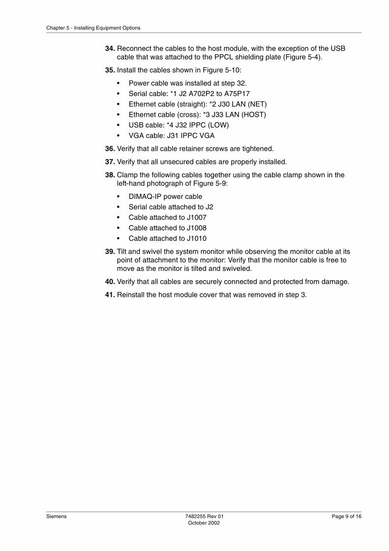
Siemens 7482255 Rev 01 Page 9 of 16October 2002
Chapter 5 - Installing Equipment Options
34. Reconnect the cables to the host module, with the exception of the USB cable that was attached to the PPCL shielding plate (Figure 5-4).
35. Install the cables shown in Figure 5-10:
• Power cable was installed at step 32.
• Serial cable: *1 J2 A702P2 to A75P17
• Ethernet cable (straight): *2 J30 LAN (NET)
• Ethernet cable (cross): *3 J33 LAN (HOST)
• USB cable: *4 J32 IPPC (LOW)
• VGA cable: J31 IPPC VGA
36. Verify that all cable retainer screws are tightened.
37. Verify that all unsecured cables are properly installed.
38. Clamp the following cables together using the cable clamp shown in the left-hand photograph of Figure 5-9:
• DIMAQ-IP power cable
• Serial cable attached to J2
• Cable attached to J1007
• Cable attached to J1008
• Cable attached to J1010
39. Tilt and swivel the system monitor while observing the monitor cable at its point of attachment to the monitor: Verify that the monitor cable is free to move as the monitor is tilted and swiveled.
40. Verify that all cables are securely connected and protected from damage.
41. Reinstall the host module cover that was removed in step 3.

Page 10 of 16 7482255 Rev 01 Siemens October 2002
Installing the G50 DIMAQ-IP
42. Attach the DIMAQ-IP option label at the designated option-label location.
1.4 Testing the DIMAQ-IP
Use the following steps to test the DIMAQ-IP module.
1. Connect the G50 power cord to the outlet, and energize the G50 system.
2. Verify that the G50 initializes without displaying error messages.
3. Press the Review key.
4. Verify that the DIMAQ-IP Digital Lab screen is displayed.
5. Verify that the DICOM Screen menu item is listed on the Change Screen menu located at the lower-left side of the screen: This indicates that the DIMAQ-IP software is version 1.2 or greater.
6. Operate the trackball and verify that the pointer moves across the screen.
7. Use the Digital Lab features to process several studies.
1.5 Removing the DIMAQ-IP Module
See "Removing and Installing the DIMAQ-IP Module" (page 4-24) for remove and replace procedures appropriate for both the G50 and the G60 S DIMAQ-IP module.
Figure 5-10 Installing DIMAQ-IP and Host Module Cables
*1*2
*3*4
*5
*5: VGA cable
Host Module

Siemens 7482255 Rev 01 Page 11 of 16October 2002
Chapter 5 - Installing Equipment Options
2.0 Installing the G50 Third Array PortUse the instructions provided in this section to add a third array port to the G50 system.
2.1 Kit
Table 5-2 lists the contents of the kit provided for the installation of the additional array port on the G50.
2.2 Tools Required
A number 2 Phillips screwdriver is required to perform this procedure.
2.3 Installing the Array Port
Use the following instructions to disassemble the G50 and install the additional array port.
1. Verify that the system software is equal or greater than version 1.2.0; the additional port installed according to this procedure cannot be activated if an earlier version of system software is installed on the G50. If the system software requires upgrade to version 1.2.0, arrange to perform that task.
2. Move the G50 to a level location that provides 1 meter of clearance at the front and sides of the system.
3. Lock the 4 wheel locks.
4. De-energize the G50 and detach the power cord from the power outlet.
� Caution: The tasks described in this procedure expose static sensitive compo-nents in the G50 to electrostatic discharge (ESD). Observe prescribed ESD pro-cedures.
Table 5-2 Kit Contents
Part Part Number or Description
Quantity
A36 A3RD-2 PCB 78 40 221 1
M4 X 8 Screw Binding head, external lock washer
2
M3 X 8 Screw Binding head, external lock washer
6
Option Label 1
Note: In the following figures, fasteners are referenced as CK3 X 8 and CK4 X 8. See "Fastener Reference" (page H-1) for information on these fastener designa-tions.

Page 12 of 16 7482255 Rev 01 Siemens October 2002
Installing the G50 Third Array Port
5. Detach all transducers from the G50.
6. As depicted in Figure 5-11, loosen the two screws located at the bottom of the front cover of the G50.
7. Pull the top of the front cover away from the G50 to release the three pairs of magic fasteners (Figure 5-11).
8. Grasp the top of the front cover and one of the bumpers; pull and detach the front cover from the G50.
9. Remove the two labels indicated in Figure 5-12 from the front of the probe interface panel; these labels carry the message, “Do not open.”
10. Discard the two (“Do not open”) labels; they will not be reinstalled.
11. As indicated in Figure 5-12, remove the 12 screws (M4 X 8); retain these screws for reinstallation during the reassembly of the G50.
12. After removing the 12 screws, pull the plastic loop (Figure 5-12) toward the front of the G50 to remove the probe interface panel.
13. From the rear of the probe interface panel just removed, unscrew the two screws to release the blank panel indicated in Figure 5-12.
Figure 5-11 Removing the Front Cover
Front cover
Magic fastener (3)
Screw (2)
Bumper
Main unit

Siemens 7482255 Rev 01 Page 13 of 16October 2002
Chapter 5 - Installing Equipment Options
14. Discard the blank panel and the two screws that were removed from it.
15. Orient the A36 A3RD-2 board shown in Figure 5-13 to the A36 PSEL PCB.
16. Align the connectors on the A36 A3RD-2 PCB to the PSEL PCB.
17. Press the connectors of the A36 A3RD-2 PCB into the matching connec-tors (P20, P21, P22, and P23) of the PSEL PCB.
18. Install the six M3 X 8 screws, provided in the kit, through the A36 A3RD-2 PCB and into the PSEL PCB as shown in Figure 5-13.
19. As indicated in Figure 5-14, reinstall the probe interface panel on the front of the G50, using the twelve M4 X 8 screws that were removed in step 11.
Figure 5-12 Removing the Probe Interface Panel
Remove two screwsfrom the reverseto remove theblank panel
Pull the loop to open
Remove theseCK4 X 8screws (12) fromthe front side.
“Do not open” label
“Do not open” label
Probe Interface Shield
Figure 5-13 Installing the A36 A3RD-2 PCB
P21
P21
P23
P23
P22
P22
P20
P20
A36 PSEL PCB
36 A3RD-2 PCBFastenCK3 x 8 screw (6)supplied with this kit
FastenCK4 x 8 screw (2)supplied with this kitafter installing ProbeInterface Shield
Probe Interface Shield
Connect P20, P21, P22, and P23when installing A36 A3RD-2 PCBonto A36 PSEL PCB.

Page 14 of 16 7482255 Rev 01 Siemens October 2002
Installing the G50 Third Array Port
20. Install the two M4 X 8 screws, provided in the kit, to secure the transducer connector of the A36 A3RD-2 PCB to the probe interface panel (Figure 5-14).
21. Reinstall the front cover of the G50: See steps 6 through 8.
22. Install the option label, provided in the kit, at the designated location on the rear of the G50.
2.4 Removing the Array Port
If it becomes necessary to remove or replace the A36 A3RD-2 PCB, use the installation instructions in reverse sequence to remove the PCB. If the option is to be permanently removed, remove the option label from the rear of the system.
2.5 Testing the Array Port
Use the following instructions to test the newly installed A36 A3RD-2 PCB.
1. Verify that the system software is equal or greater than version 1.2.0; the additional port installed according to this procedure cannot be activated if an earlier version of system software is installed on the G50.
2. Connect any transducer to the newly installed port.
3. Energize the G50.
4. Verify that the clock located in the upper right corner of the screen displays the proper time; if not adjust the time.
5. Display a 2D-image screen for the transducer attached to the new port.
6. At the keyboard, press the F4 key to display the Preset Main Menu.
7. Activate the service software according the instructions provided in "Ser-vice Software Operation" (page 8-17).
8. Select the HW/SW button located on the Main Menu screen to display the System Configuration – Hardware screen as shown in Figure 5-15.
9. Scroll down the list, displayed on this screen, to the A36-2 assembly.
Figure 5-14 Installing the Probe Interface Panel
Probe Interface Shie
FastenCK4 x 8 screw (12)
36 A3RD-2Transducer connector (3rd port)
FastenCK4 x 8 screw (2)
su lied with this kit

Siemens 7482255 Rev 01 Page 15 of 16October 2002
Chapter 5 - Installing Equipment Options
10. Verify that an assembly number is displayed in the AS No. field for the A36-2 PCB (Figure 5-15).
11. Select the Home button to return to the Main Menu screen.
12. Select the Exit button exit the Service software; the ultrasound imaging screen will be displayed.
13. Acquire an ultrasound image, using the probe attached to the new port.
14. Verify that no vertical line or image noise is present on the acquired image.
15. Verify that the option label for the new port is attached at the rear of the sys-tem.
16. The new port is now properly installed and operational.
Note: If the A36 A3RD-2 PCB is not installed in the G50, the screen shown in Figure 5-16 will display the message “Not Installed” in the AS No. column for the A36-2 PCB on the System Configuration – Hardware screen.
Figure 5-15 System Configuration – Hardware Screen (A36-2 Installed)
Home
Hardware
Software
Peripheral
System Configuration - Hardware
Service
Site
System
HW/SW
Assy No. Assy Name AS No.
A10 OPCT 0
A30 ECGX 101
A36 PSEL Not Install ed
A36- 2 A3RD 2
A40 PAMP Not Install ed
A40- 1 CWRX Not Install ed
A40- 3 RX32 Not Install edIf A36 A3RD-2 PCB has beensuccessfully installed, a numericvalue is shown here.
XXXX

Page 16 of 16 7482255 Rev 01 Siemens October 2002
Installing the G50 Third Array Port
Figure 5-16 System Configuration – Hardware Screen (A36-2 Not Installed)
Note: To confirm the successful removal of the A36 A3RD-2 PCB, verify that “Not Installed” is displayed in the System Configuration – Hardware screen as shown in Figure 5-16.
Home
Hardware
Software
Peripheral
System Configuration - Hardware
Service
Site
System
HW/SW
Assy No. Assy Name AS No.
A10 OPCT 0
A30 ECGX 101
A36 PSEL Not Install ed
A36- 2 A3RD 2 Not Installed
A40 PAMP Not Install ed
A40- 1 CWRX Not Install ed
A40- 3 RX32 Not Install edIf A36 A3RD-2 PCB has beensuccessfully de-installed, “Not Installed” isshown here.

Siemens 7482255 Rev 01 Page 1 of 22October 2002
Chapter 6 - Troubleshooting
Chapter 6: TroubleshootingThis chapter provides troubleshooting methods and information for the G50 and the G60 S.
The following topics are presented in this chapter:
1.0 Verifying the System Operation ....................................................6-2
2.0 Diagnostic Messages ....................................................................6-3
3.0 Diagnostic Indicators ....................................................................6-9
4.0 Troubleshooting the DIMAQ-IP .....................................................6-11
5.0 Rebooting the System Software ...................................................6-12
6.0 Diagnostic Flow Charts .................................................................6-13

Page 2 of 22 7482255 Rev 01 Siemens October 2002
Verifying the System Operation
1.0 Verifying the System OperationUse the following methods to verify that the G50 or the G60 S is operating properly.
See Instructions for Use for detailed operating instructions.
1.1 Verifying the Operation of the System
1. Connect the power cable to the wall outlet.
2. Connect a transducer to the ultrasound system.
3. Turn the power switch On.
4. Turn the Standby switch On.
5. Confirm that a B-mode image is displayed on the monitor.
6. Verify that a Color flow image is displayed on the monitor.
7. Verify that the Doppler spectrum is displayed on the monitor.
8. Verify that the ECG trace is displayed on the monitor.
1.2 Verifying the Operation of the Peripherals
Use the following instructions to verify the operation of peripherals attached to the G50 or the G60 S.
1. Turn on the power switch of the P91W printer.
2. Press F4 to display the Menu screen on the monitor.
3. Move the trackball upward and select Customize Keys from the left frame displayed on the screen.
4. Press SET.
5. In the right frame of the displayed screen, select B/W Print for PRINT/STORE 1 key.
6. Move the cursor to the radio button labeled B/W Print, and press SET.
7. Select B/W Printer for Set Up for PRINT/STORE 1 key and press SET.
8. Select Save and press SET.
9. Press PRINT/STORE 1.
10. Confirm that the B-mode image on the monitor is printed correctly on the P91W printer.
11. Turn on the power switch of the CP900 color printer.
12. Press F4 to display the Menu screen on the monitor.
13. Move the trackball upward and select Customize Keys from the submenu.
14. Press SET.

Siemens 7482255 Rev 01 Page 3 of 22October 2002
Chapter 6 - Troubleshooting
15. Select Color Print for Set Up for PRINT/STORE 2 key and press SET.
16. Select Save and press SET.
17. Press the Menu key on the CP900 remote control.
18. Select Signal Set and set the input to RGB.
19. Press PRINT 2.
20. Confirm that the B-mode image on the monitor is printed correctly on the CP900 printer.
21. Turn on the power switch of SVO-9500 VCR and insert a S-VHS tape into the VCR.
22. Press F4 to display the Menu screen on the monitor.
23. Move the trackball upward and select Peripheral from the submenu.
24. Press SET.
25. Select S-VHS for Video Input Source and press SET.
26. Select VCR for the External RS-232C Port 1 and press SET.
27. Select Save and press SET.
28. Press the D key twice to invoke 2D + pwD mode.
29. Press RECORD to record the image and sound.
30. After pressing VIDEO I/O, press REWIND on the LCD, then press PLAY to review the image and the sound just recorded.
31. Confirm that no error message is displayed on the monitor.
1.3 Verifying the Operation of the DIMAQ-IP Module
1. Press REVIEW.
2. Confirm that the monitor shows DIMAQ-IP module (Digital Lab) screen.
3. Move the trackball: Confirm that the cursor follows the movement of track-ball.
2.0 Diagnostic MessagesTable 6-1, “Diagnostic Messages,” on page 6-4 lists the diagnostic messages and the error messages likely to be encountered when a failure occurs on a specific printed circuit board (PCB).

Diagnostic Messages
Page 4 of 22 7482255 Rev 01 Siemens October 2002
Tab
le 6
-1D
iagn
ostic
Mes
sage
s (S
heet
1 o
f 5)
No
.D
iag
no
stic
s M
essa
ge
Err
or
Lo
g M
essa
ge
Exp
ecte
d
Fai
lure
Lo
cati
on
Fai
led
P
CB
F
aile
d
PC
B
Nam
e
1F
ail :
Ope
rato
r: a
dd=0
xXX
XX
val
(0x5
5)=
0xX
XF
ail :
Ope
rato
r: a
dd=
0xX
XX
X v
al(0
x55)
=0xX
XC
ontr
ol P
anel
A10
OP
CT
2F
ail :
Ope
rato
r: a
dd=0
xXX
XX
val
(0xa
a)=
0xX
XF
ail :
Ope
rato
r: a
dd=
0xX
XX
X v
al(0
xaa)
=0xX
XC
ontr
ol P
anel
A10
OP
CT
3F
ail :
Hos
tBox
: H
ostB
ox R
etur
n P
ath(
Car
d-H
ost T
est P
at.)
Fai
l : H
ostB
ox :
Hos
tBox
Ret
urn
Pat
h(C
ard-
Hos
t Tes
t Pat
.)H
ost M
odul
eA
70D
VS
C
4F
ail :
Car
dBox
: C
ardB
ox R
etur
n P
ath(
Car
d-H
ost T
est P
at.)
Fai
l : C
ardB
ox :
Car
dBox
Ret
urn
Pat
h(C
ard-
Hos
t Tes
t Pat
.)E
Mod
ule
-E
Mod
ule
5F
ail :
Hos
tBox
: H
ostB
ox T
est P
at. G
en.(
Car
d-H
ost T
est P
at.)
Fai
l : H
ostB
ox :
Hos
tBox
Tes
t Pat
. Gen
.(C
ard-
Hos
t Tes
t Pat
.)H
ost M
odul
eA
70D
VS
C
6F
ail :
Car
dBox
: C
ardB
ox(C
ard-
Hos
t Tes
t Pat
.)F
ail :
Car
dBox
: C
ardB
ox(C
ard-
Hos
t Tes
t Pat
.)E
Mod
ule
A66
DT
PS
7F
ail :
Car
d/H
ost:
Car
dBox
and
Hos
tBox
(Car
d-H
ost T
est P
at.)
Fai
l :C
ard/
Hos
t: C
ardB
ox a
nd H
ostB
ox(C
ard-
Hos
t Tes
t Pat
.)E
Mod
ule
or H
ost
Mod
ule
A66
/A70
DT
PS
/D
VS
C
8F
ail :
Cab
le :
Cab
le b
etw
een
Car
d an
d H
ost(
Car
d-H
ost T
est
Pat
.)F
ail :
Cab
le :
Cab
le b
etw
een
Car
d an
d H
ost(
Car
d-H
ost T
est
Pat
.)C
able
bet
wee
n E
M
odul
e an
d H
ost
Mod
ule
-C
able
9F
ail :
Hos
tBox
: H
ostB
ox(C
ard-
Hos
t Tes
t Pat
.)F
ail :
Hos
tBox
: H
ostB
ox(C
ard-
Hos
t Tes
t Pat
.)H
ost M
odul
eA
70D
VS
C
10F
ail :
Hos
tBox
: H
ostB
ox R
etur
n P
ath(
DIM
AQ
-IP
-Hos
t Tes
t P
at.)
Fai
l : H
ostB
ox :
Hos
tBox
Ret
urn
Pat
h(D
IMA
Q-I
P-H
ost T
est
Pat
.)H
ost M
odul
eA
70D
VS
C
11F
ail :
DIM
AQ
-IP
: D
IMA
Q-I
P R
etur
n P
ath(
DIM
AQ
-IP
-Hos
t Te
st P
at.)
Fai
l : D
IMA
Q-I
P
: DIM
AQ
-IP
Ret
urn
Pat
h(D
IMA
Q-I
P-H
ost
Test
Pat
.)D
IMA
Q-I
PA
75S
PC
L
12F
ail :
Hos
tBox
: H
ostB
ox T
est P
at. G
en.(
DIM
AQ
-IP
-Hos
t Tes
t P
at.)
Fai
l : H
ostB
ox :
Hos
tBox
Tes
t Pat
. Gen
.(D
IMA
Q-I
P-H
ost T
est
Pat
.)H
ost M
odul
eA
70D
VS
C
13F
ail :
DIM
AQ
-IP
: D
IMA
Q-I
P(D
IMA
Q-I
P-H
ost T
est P
at.)
Fai
l : D
IMA
Q-I
P
: DIM
AQ
-IP
(DIM
AQ
-IP
-Hos
t Tes
t Pat
.)D
IMA
Q-I
PA
75S
PC
L
14F
ail :
DIM
AQ
-IP
/Hos
t: D
IMA
Q-I
P a
nd H
ostB
ox(D
IMA
Q-I
P-
Hos
t Tes
t Pat
.)F
ail :
DIM
AQ
-IP
/Hos
t: D
IMA
Q-I
P a
nd H
ostB
ox(D
IMA
Q-I
P-H
ost
Test
Pat
.)D
IMA
Q-I
P o
r H
ost M
odul
eA
70/A
75D
VS
C/
SP
CL

Siemens 7482255 Rev 01 Page 5 of 22October 2002
Chapter 6 - Troubleshooting
15F
ail :
Cab
le :
Cab
le b
etw
een
DIM
AQ
-IP
and
Hos
t(D
IMA
Q-I
P-
Hos
t Tes
t Pat
.)F
ail :
Cab
le :
Cab
le b
etw
een
DIM
AQ
-IP
and
Hos
t(D
IMA
Q-I
P-
Hos
t Tes
t Pat
.)C
able
bet
wee
n E
M
odul
e an
d D
IMA
Q-I
P
-C
able
16F
ail :
Hos
tBox
: H
ostB
ox(D
IMA
Q-I
P-H
ost T
est P
at.)
Fai
l : H
ostB
ox :
Hos
tBox
(DIM
AQ
-IP
-Hos
t Tes
t Pat
.)H
ost M
odul
eA
70D
VS
C
17F
ail :
Hos
tBox
: D
IMA
Q-I
P-H
ostB
ox T
est
Fai
l : H
ostB
ox :
DIM
AQ
-IP
-Hos
tBox
Tes
tH
ost M
odul
eA
70D
VS
C
18F
ail :
Hos
tBox
: C
ardB
ox-H
ostB
ox T
est
Fai
l : H
ostB
ox :
Car
dBox
-Hos
tBox
Tes
tH
ost M
odul
eA
70D
VS
C
19W
ork
Mem
ory
Err
or!
-R
ecyc
le p
ower
. If
the
erro
r m
es-
sage
is d
ispl
ayed
ag
ain,
exc
hang
e H
ost M
odul
e.
-/A
70-/
DV
SC
20F
ail :
D+3
VA
+3V
=U
pper
Vol
tage
Err
or! :
V=
XX
XX
et
cP
ower
Mod
ule
A03
/A07
SW
RG
/P
DS
T
21F
ail :
A-1
0VA
-10V
=Lo
wer
Vol
tage
Err
or! :
V=
XX
XX
et
cP
ower
Mod
ule
22F
ail :
A+
5VA
+5V
=Lo
wer
Vol
tage
Err
or! :
V=
XX
XX
et
cP
ower
Mod
ule
A03
/A07
SW
RG
/P
DS
T
23F
ail :
D+5
VD
+5V
=Low
er V
olta
ge E
rror
! : V
=X
XX
X
etc
Pow
er M
odul
eA
03/A
07S
WR
G/
PD
ST
24F
ail :
A-1
2VA
-12V
=Lo
wer
Vol
tage
Err
or! :
V=
XX
XX
et
cP
ower
Mod
ule
A03
/A07
SW
RG
/P
DS
T
25F
ail :
A+
12V
A+
12V
=Lo
wer
Vol
tage
Err
or! :
V=
XX
XX
et
cP
ower
Mod
ule
A03
/A07
SW
RG
/P
DS
T
26F
ail :
A+
90V
A+
90V
=Lo
wer
Vol
tage
Err
or! :
V=
XX
XX
et
cP
ower
Mod
ule
A66
DT
PS
Tab
le 6
-1D
iagn
ostic
Mes
sage
s (S
heet
2 o
f 5)
No
.D
iag
no
stic
s M
essa
ge
Err
or
Lo
g M
essa
ge
Exp
ecte
d
Fai
lure
Lo
cati
on
Fai
led
P
CB
F
aile
d
PC
B
Nam
e

Diagnostic Messages
Page 6 of 22 7482255 Rev 01 Siemens October 2002
27F
ail :
D+2
4VD
+24
V=
Low
er V
olta
ge E
rror
! : V
=X
XX
X
etc
Pow
er M
odul
e
28F
ail :
HV
-37V
HV
-37V
=Lo
wer
Vol
tage
Err
or! :
V=
XX
XX
et
cP
ower
Mod
ule
A66
DT
PS
29F
ail :
A+
BV
A+
BV
=Lo
wer
Vol
tage
Err
or! :
V=X
XX
X
etc
Pow
er M
odul
eA
66D
TP
S
30F
ail :
A-9
0VA
-90V
=Lo
wer
Vol
tage
Err
or! :
V=
XX
XX
et
cP
ower
Mod
ule
A66
DT
PS
31F
ail :
HV
+155
VH
V+
155V
=Lo
wer
Vol
tage
Err
or! :
V=X
XX
X
etc
Pow
er M
odul
eA
66D
TP
S
32F
ail :
No
data
in E
EP
RO
M o
f DV
SC
-E
nter
EE
PR
OM
da
ta in
DV
SC
E
EP
RO
M.
A70
DV
SC
33F
ail :
Hos
tBox
: S
DR
AM
Err
orD
VS
C :
SD
RA
M R
ead/
Writ
e E
rror
Hos
t Mod
ule
A70
DV
SC
34F
ail :
Hos
tBox
: S
RA
M E
rror
DV
SC
: S
RA
M R
ead/
Writ
e E
rror
Hos
t Mod
ule
A70
DV
SC
35F
ail :
Hos
tBox
: R
TC
Err
orD
VS
C :
RT
C fu
nctio
n E
rror
Hos
t Mod
ule
A70
DV
SC
36F
ail :
Hos
tBox
: S
CS
I Err
orD
VS
C :
SC
SI C
ontr
olle
r R
egis
ter
Err
orH
ost M
odul
eA
70D
VS
C
37F
ail :
Hos
tBox
: F
lash
RO
M E
rror
DV
SC
: F
lash
RO
M R
ead
Err
orH
ost M
odul
eA
70D
VS
C
38F
ail :
Car
dBox
: R
XB
FA R
egis
ter
Err
orR
XB
F A
: R
egis
ter
Rea
d/W
rite
Err
orE
Mod
ule
A46
RX
BF
A
39F
ail :
Car
dBox
: R
XB
FB
Reg
iste
r E
rror
RX
BF
B :
Reg
iste
r R
ead/
Writ
e E
rror
E M
odul
eA
46R
XB
F B
40F
ail :
No
data
in E
EP
RO
M o
f RX
BF
B-
Ent
er E
EP
RO
M
data
in R
XB
FB
E
EP
RO
M.
A46
RX
BF
B
41F
ail :
Car
dBox
: B
WP
P C
ME
M(M
) E
rror
BW
PP
: C
ME
M(B
)63
Rea
d/W
rite
Err
orE
Mod
ule
A51
on
A48
CM
EM
on
BW
PP
42F
ail :
Car
dBox
: B
WP
P C
ME
M(M
) E
rror
BW
PP
: C
ME
M(B
)255
Rea
d/W
rite
Err
orE
Mod
ule
A51
on
A48
CM
EM
on
BW
PP
Tab
le 6
-1D
iagn
ostic
Mes
sage
s (S
heet
3 o
f 5)
No
.D
iag
no
stic
s M
essa
ge
Err
or
Lo
g M
essa
ge
Exp
ecte
d
Fai
lure
Lo
cati
on
Fai
led
P
CB
F
aile
d
PC
B
Nam
e

Siemens 7482255 Rev 01 Page 7 of 22October 2002
Chapter 6 - Troubleshooting
43F
ail :
Car
dBox
: S
UB
C R
UN
Err
orS
UB
C :
RA
CS
Run
Err
orE
Mod
ule
A50
SU
BC
44F
ail :
No
data
in E
EP
RO
M o
f SU
BC
-E
nter
EE
PR
OM
da
ta in
SU
BC
E
EP
RO
M.
A50
SU
BC
45F
ail :
Car
dBox
: C
FP
R C
ME
M(M
c) E
rror
CF
PR
: C
ME
M(M
c) R
ead/
Writ
e E
rror
E M
odul
eA
56C
FP
R
46F
ail :
Car
dBox
: C
FP
R C
ME
M(V
) E
rror
CF
PR
: C
ME
M(V
)63
Rea
d/W
rite
Err
orE
Mod
ule
A56
CF
PR
47F
ail :
Car
dBox
: C
FP
R C
ME
M(V
) E
rror
CF
PR
: C
ME
M(V
)255
Rea
d/W
rite
Err
orE
Mod
ule
A56
CF
PR
48F
ail :
Car
dBox
: C
FP
R C
ME
M(T
P)
Err
orC
FP
R :
CM
EM
(TP
)63
Rea
d/W
rite
Err
orE
Mod
ule
A56
CF
PR
49F
ail :
Car
dBox
: C
FP
R C
ME
M(T
P)
Err
orC
FP
R :
CM
EM
(TP
)255
Rea
d/W
rite
Err
orE
Mod
ule
A56
CF
PR
50F
ail :
Car
dBox
: C
FP
R R
AM
(Noi
seC
utF
PG
A)
Err
orC
FP
R :
Noi
se C
ut F
PG
A U
38 E
rror
E M
odul
eA
56C
FP
R
51F
ail :
Car
dBox
: C
FP
R S
DR
C(U
14, U
19)
Err
orC
FP
R :
SD
RC
U14
,U19
Err
orE
Mod
ule
A56
CF
PR
52F
ail :
Car
dBox
: C
FP
R F
PG
A(U
38)
Err
orC
FP
R :
Noi
se C
ut F
PG
A R
AM
Err
orE
Mod
ule
A56
CF
PR
53F
ail :
Car
dBox
: C
FP
R A
SIC
(U20
) E
rror
CF
PR
: C
FP
2 A
SIC
U20
Err
orE
Mod
ule
A56
CF
PR
54F
ail :
Car
dBox
: C
FP
R L
UT
RA
M(U
4) E
rror
CF
PR
: LU
T R
AM
U4
Err
orE
Mod
ule
A56
CF
PR
55F
ail :
No
data
in E
EP
RO
M o
f CF
PR
-E
nter
EE
PR
OM
da
ta in
CF
PR
E
EP
RO
M.
A56
CF
PR
56F
ail :
Car
dBox
: D
PP
R(D
SP
) R
un E
rror
DP
PR
: D
SP
Pro
gram
Han
g up
E M
odul
eA
56-1
DP
PR
57F
ail :
Car
dBox
: D
PP
R(D
SP
) M
islo
adin
gD
PP
R :
DS
P P
rogr
am L
oadi
ng E
rror
E M
odul
eA
56-1
DP
PR
58F
ail :
Car
dBox
: D
PP
R(D
SP
) In
ital E
rror
DP
PR
: D
SP
Pro
gram
Init
Err
orE
Mod
ule
A56
-1D
PP
R
59F
ail :
Car
dBox
: D
PP
R C
ME
M(D
) E
rror
DP
PR
: C
ME
M(D
) R
ead/
Writ
e E
rror
E M
odul
eA
56-1
DP
PR
Tab
le 6
-1D
iagn
ostic
Mes
sage
s (S
heet
4 o
f 5)
No
.D
iag
no
stic
s M
essa
ge
Err
or
Lo
g M
essa
ge
Exp
ecte
d
Fai
lure
Lo
cati
on
Fai
led
P
CB
F
aile
d
PC
B
Nam
e

Diagnostic Messages
Page 8 of 22 7482255 Rev 01 Siemens October 2002
60F
ail :
No
data
in E
EP
RO
M o
f DP
PR
-E
nter
EE
PR
OM
da
ta in
CF
PR
E
EP
RO
M.
A56
-1D
PP
R
61-
FAN
Sto
p E
rror
MO
, Sof
twar
e R
egul
ated
Fan
, or
Rea
r FA
N is
st
oppe
d
-M
O F
an,
Rea
r P
anel
Fan
, or
SW
RG
F
an
62-
Tem
pera
ture
Err
orE
Mod
ule
--
63-
War
ning
: O
pera
tor
is n
ot c
onne
cted
.C
ontr
ol P
anel
A10
OP
CT
64-
SR
AM
Err
or C
ode
XX
XX
Hos
t Mod
ule
A70
DV
SC
Tab
le 6
-1D
iagn
ostic
Mes
sage
s (S
heet
5 o
f 5)
No
.D
iag
no
stic
s M
essa
ge
Err
or
Lo
g M
essa
ge
Exp
ecte
d
Fai
lure
Lo
cati
on
Fai
led
P
CB
F
aile
d
PC
B
Nam
e

Siemens 7482255 Rev 01 Page 9 of 22October 2002
Chapter 6 - Troubleshooting
3.0 Diagnostic IndicatorsDiagnostic light emitting diodes (LEDs), located on the side of the host module, provide indications of the boot progress, the system status, and some subsystem failures. The legend shown in Figure 6-1 depicts the LED status for the Off (extinguished), On (illuminated), and flashing (On–Off) conditions.
Table 3-1, “Component Designations,” on page 3-2 identifies the acronyms that are used in this chapter to identify devices.
Figure 6-2 shows the status of the LEDs as they are progressively extinguished during the boot sequence. Figure 6-3 shows the LED status after boot is completed, both with and without the DIMAQ-IP module connected.
Figure 6-1 LED Legend
LED Off
LED On
LED Cycling On and Off
LED Legend
The LEDs in the following diagrams are depicted according to the legend pre-sented to the left.
Note: The LED designated with the V character represents the 5V supply. This LED is illuminated when 5V power is available.

Page 10 of 22 7482255 Rev 01 Siemens October 2002
Diagnostic Indicators
Figure 6-2 Diagnostic LED Status During the Boot Sequence
1 2 3 4 5 6 7 8 V
Begin Boot
Initialize CPU (DVSC)Initialize SDRAM (DVSC)
Initialize Video Output
Light on Other LEDs
Initialize SerialInitialize DVSCInitialize Graphic Function
Initialize the ConnectionBetween Control Panel and theG60 S
Display LCD and Startup Image
Display Progress Bar
Set RTC
Copy System Software from Flash ROMBoot Windows CE and System SoftwareBoot Complete
Boot Sequence

Siemens 7482255 Rev 01 Page 11 of 22October 2002
Chapter 6 - Troubleshooting
After completion of the boot sequence, the LEDs shown in Figure 6-3 indicate the following conditions:
� LED 1 illuminates only during the boot sequence. When Off, it indicates that the boot sequence has been completed.
� LED 2 illuminates after completion of the boot sequence, if the Windows-CE and system software have been initialized.
� LED 3 flashes after completion of the boot sequence, when keys, encod-ers, or volumes are operated.
� LED 4 illuminates after completion of the boot sequence to indicate that the DSP on the DPPR has malfunctioned.
� LED 5 illuminates after completion of the boot sequence, to indicate that the DIMAQ-IP module is connected.
� LED 6 flashes at one second intervals to indicate that the CPU is operating.
� LED 7 illuminates when a cooling fan fails: The MO fan, two E module fans, and two switching regulator fans are included in this circuit.
� LED 8 illuminates when the temperature in the E module exceeds the over-temperature limit of 80 °C (176 °F).
4.0 Troubleshooting the DIMAQ-IPUse the following instructions to troubleshoot the DIMAQ-IP.
4.1 Review Switch Failure
If the DIMAQ-IP screen does not appear when the REVIEW control is selected, use the following instructions to troubleshoot the failure.
1. Verify that a patient name and ID number are entered.
2. Verify that HDD is selected (not MOD) for Storage on the Preset Menu.
3. Access DIMAQ-IP through the Service Menu by selecting DIMAQ-IP Main-tenance; a blank screen indicates a DIMAQ-IP failure.
If the trackball and SET or ENTER operate properly, the DIMAQ-IP soft-ware and Windows are running, but applications are not active. Loss of the trackball control indicates the loss of the internal Ethernet communication. Restart the DIMAQ-IP by rebooting Windows 2000 (Start → Restart).
Figure 6-3 Diagnostic LED Status After Boot Completed
System without DIMAQ-IP after Boot
System with DIMAQ-IP after Boot

Page 12 of 22 7482255 Rev 01 Siemens October 2002
Rebooting the System Software
Observe the screen during the reboot to detect HDD error messages. If errors are detected, run the Scan Disk application from the Start → Pro-grams → Accessories → System Tools menu. If no errors are detected on the HDD, reboot the system.
4. If DIMAQ-IP still does not function properly, load new DIMAQ-IP software.
4.2 Corrupted Images and Clips
If, when REVIEW is selected, corrupted images or clips are displayed, the following failures can be the cause.
1. New images or clips produced by real-time scanning are corrupted, but images loaded from studies on the HDD or from a CD are not corrupted.
Corruption of ultrasound images is caused by a failure in the host module or the failure of the image transfer path (serial). Inspect and test the host module and the serial path; replace the host module if necessary.
2. New images from real-time scanning are not corrupted, but images recalled from the HDD or from a CD are corrupted.
The corruption of images loaded from the HDD or a CD is caused by the DIMAQ-IP software or by the CD-R/W drive software. Reload the DIMAQ-IP software to resolve the problem.
5.0 Rebooting the System SoftwareUse the following instructions to reboot the system software after a system failure.
Powering down and re-energizing the G50 or the G60 S will perform a complete (cold) boot of all subsystem software.
The following instructions describe the re-boot of the system software only (soft or warm boot). Use this procedure if the system locks up.
1. Press and hold down the New Patient key.
2. Locate the key bearing the small square on its key cap: This key is located above the VCR key.
3. Press and hold down the key bearing the small square on its key cap.
4. Press and hold down the Freeze key: Press and hold the New Patient + Square + Freeze keys to perform a soft boot of the system software.
Note: The re-boot of the DIMAQ-IP is described in "Review Switch Failure" (page 6-11).

Siemens 7482255 Rev 01 Page 13 of 22October 2002
Chapter 6 - Troubleshooting
6.0 Diagnostic Flow ChartsFigure 6-4 through Figure 6-12 provide a series of flow charts for troubleshooting a malfunctioning G50 or G60 S.
Table 3-1, “Component Designations,” on page 3-2 identifies the acronyms that are used in this chapter to identify devices.
Use the hyperlinks on page 6-14 to jump to the chart indicated by the symptom encountered.
Refer to the following chapters in this manual for additional information:
� Chapter 2; "System Architecture" (page 2-1)
� Chapter 3; "Power Distribution" (page 3-1)
The remove and replace procedures for the major components are included in "Removing and Replacing Spare Parts" (page 4-1).
�Warning: The G50 and the G60 S contain hazardous voltages that can range from 90 Vac to 264 Vac. These voltages can cause serious injury or death. Only authorized service personnel are permitted to remove protective covers and access the energized components of this sys-tem.

Page 14 of 22 7482255 Rev 01 Siemens October 2002
Diagnostic Flow Charts
Figure 6-4 Troubleshooting Flow Chart (Starting Page)
Start
Boot-up Ok? Replace Host ModuleNo
Monitor Ok?
Control PanelOk?
B-mode Ok?
Color Flow Ok?
Doppler Ok?
ECG Ok?
OEM andPeripherals
Ok?
IPPC ModuleOk?
End
Yes
Yes
Yes
Yes
Yes
Yes
Yes
Yes
Yes
No
Resolved
A
BNo
C
D
E
F
G
H
No
No
No
No
No
No
Resolved
Resolved
Resolved
Resolved
Resolved
Resolved
Resolved
Figure 6-8 Chart D: Color Flow
Figure 6-6 Chart B: Control Panel
Figure 6-7 Chart C: B-mode Imaging
Figure 6-5 Chart A: Monitor
Figure 6-9 Chart E: Doppler
Figure 6-10 Chart F: ECG
Figure 6-12 Chart H: DIMAQ-IP
Figure 6-11 Chart G: OEMs and Peripherals
Hyperlinks

Siemens 7482255 Rev 01 Page 15 of 22October 2002
Chapter 6 - Troubleshooting
Figure 6-5 Chart A: Monitor
A
Monitor LEDgreen?
Displayedimage Ok?
Return
Monitor LEDgreen?
Yes
Yes
No
Replace the monitor.
Replace host module.
Replace the monitor.
No:Yellow indicates no synch.
No
Yes
Monitor switch is on andpower is arriving at the
monitor.
Yes
Verify voltage and switch.No

Page 16 of 22 7482255 Rev 01 Siemens October 2002
Diagnostic Flow Charts
Figure 6-6 Chart B: Control Panel
B
Slide keyboardOk?
Main panelOk?
Sub panel Ok?
Return
LED 3 on sidepanel Ok?
No Replace slide keyboard.
Replace host module
Replace main panel.
Replace OPCT PC board
Replace OPCT PC board.
Replace sub panel.
Replace host module.
No
Yes
Push New Patient > Update >Set; select Control Panel
Selftest.
This routine tests A10; LED 3does not illuminate during the
test because nocommunication with host
module is possible.
If switch is defective, it will notilluminate, but the test willcontinue un-interrupted.
Restart system aftercompletion of the test.
LCD displayOk?
No
Test Service >Diagnostics >
Opeator (Control).Perform LCD read/writetest; it is not a complete
control panel test.
No
LCD test Ok?
LED 3 on sidepanel Ok?
Yes No
Yes
No
Yes
No Self test Ok? No
LED 3 on sidepanel Ok?
Yes
Replace main panel.
Replace host module.
No
Yes
Yes
Yes
Yes

Siemens 7482255 Rev 01 Page 17 of 22October 2002
Chapter 6 - Troubleshooting
Figure 6-7 Chart C: B-mode Imaging
C
B-mode imageOk?
Perform loop test 4.Service >
Diagnostics >E Module Package >
Pattern Check.Recycle power.
Replace host module
Replace G60 S E module.
Replace power module.
Replace E module.
Replace E module.
TX poweradjust Ok?
CINE modeOk?
All B-modeproblemsresolved?
Probe selectOk?
No
No
Yes
Yes
Yes
Yes
Return
Yes
Failed loop test 4;passed loop test 3.
Replace cable
Replace E module
No
No;4 pass3 fail
Yes;4 fail
3 pass
Perform loop test 3.Service >
Diagnostic >Power Module.
Loop test 4 and3 both Ok?
Yes
No
Test; Service >Diagnostics >
Power Module.After test pattern
check, recycle thesystem power
Power modulediagnosticpassed.
No
No
Replace E module.Yes
G60 S SystemNo
Yes
Third ArrayPort Option
InstalledNo Replace G50 LC E moduleNo
Remove ThirdArray Port and
Retest
Yes
ProblemRemains
Replace G50 LC E module
Replace G50 Third Array Port
Yes
No

Page 18 of 22 7482255 Rev 01 Siemens October 2002
Diagnostic Flow Charts
Figure 6-8 Chart D: Color Flow
D
Return
Color flowdisplay Ok?
Replace E module
Use LCD to selectcolor map.
Color mapselect Ok?
CINE modeOk?
All color flowproblemsresolved.
Yes
Yes
Yes
Yes
Replace host module.
Replace E module
Replace E module
No
No
No
No

Siemens 7482255 Rev 01 Page 19 of 22October 2002
Chapter 6 - Troubleshooting
Figure 6-9 Chart E: Doppler
E
Dopplerspectrum Ok?
Doppler traceOk?
Doppler soundOk?
CINE modeOk?
VCR playbacksound Ok?
Replace E module.
Replace E module.
Replace host module or OPCT(A10) PC board,
Replace E module.
Return
No
yes
Yes
No
No
Yes
Yes
Yes
Replace E module.No
No

Page 20 of 22 7482255 Rev 01 Siemens October 2002
Diagnostic Flow Charts
Figure 6-10 Chart F: ECG
F
ECG tracedisplay Ok?
ECG gainadjustment
Ok?
ECG displayoffset Ok?
ECG triggermode Ok?
Doppler tracedisplay Ok?
ECG trace hasred marker?
Return
Replace E module.
Replace ECG module.
Replace E module.
Replace ECG module.
Replace ECG module.
Replace E module.
Yes
Yes
Yes
Yes
No
No
No
Yes
No
No No
Yes

Siemens 7482255 Rev 01 Page 21 of 22October 2002
Chapter 6 - Troubleshooting
Figure 6-11 Chart G: OEMs and Peripherals
G
Voltage atoutlet Ok?
Black andwhite printer
Ok?
Color printerOk?
VCR recordand playback
Ok?
USB printerOk?
Foot switchOk?
Fuse Ok?
Return
Replace fuse.
Replace power module.
Replace printer or power cord.
Replace VCR or power cord.
Replace printer or power cord.
Replace host module.
Yes
Yes
Yes
No
Yes
Replace printer or power cord.
No
Yes
Yes
Yes
Printer, powercord, and switch
Ok?
Printer, powercord, and switch
Ok?
VCR, power cord,and switch Ok?
Printer, powercord, and switch
Ok?
No No
No No
No No
No No
Replace host module.
Replace host module.
Replace host module.
Replace host module.
Yes
Yes
Yes
Yes
Determine andrepair cause of
fuse loss.No

Page 22 of 22 7482255 Rev 01 Siemens October 2002
Diagnostic Flow Charts
Figure 6-12 Chart H: DIMAQ-IP
H
IPPC displayOk?
CINE clipfunction Ok?
All IPPCproblemsresolved.
Loop test 1Ok?
Loop test 2Ok?
Return
Replace IPPC module.
Replace host module.
Replace cable.
Replace IPPC module.
Replace IPPC module or hostmodule.
Perform loop test 1.Service >
Diagnostics>IPPC Pattern Check.
Perform loop test 2.Service >
Diagnostics>IPPC Pattern Check.
No
No
No
Yes
Yes
Yes
Yes
Yes
No
No

Siemens 7482255 Rev 01 Page 1 of 8October 2002
Chapter 7 - Installing the Version 1.2 Software Update on the G60 S
Chapter 7: Installing the Version 1.2 Software Update on the G60 S
This chapter provides instructions for the installation of the version 1.2 software update on the G60 S system.
Perform these procedures in the sequence listed:
"Installing the Version 1.2 Software Update" (page 7-2)
"Verifying the Operation of the Software" (page 7-7)
Note: Perform the complete procedure provided in this chapter, in the sequence listed, to update the G60 S system and DIMAQ-IP software to version 1.2.
Use the general instructions provided in "Software" (page 8-1) for the installation of other software updates. See "Installing or Updating the System Software" (page 8-2) and "Installing or Updating the DIMAQ-IP Software" (page 8-7).

Page 2 of 8 7482255 Rev 01 Siemens October 2002
Installing the Version 1.2 Software Update
1.0 Installing the Version 1.2 Software UpdateUse the following instructions to install the version 1.2 software update on the G60 S.
1.1 Preparing for the Version 1.2 Software Update
Use the following instructions to prepare for the installation of the version 1.2 software update.
The original release of the G60 S contained version 1.0 system software and version 1.022 DIMAQ-IP software. The Speed Info 011/2002/US describes the update of the version 1.022 DIMAQ-IP software to version 1.023.
1.1.1 Backing Up Service Data
Use the following steps to back up the service data.
1. Energize the G60 S.
2. Press the F4 key to display the Preset screen.
3. Select Service from the menu.
4. Enter the password and select the Ok button to display the service software Main Menu screen.
5. Select the Backup/Restore button to display the Backup / Restore screen.
6. Select the Backup radio button located at the top of the screen.
7. Check the All Packages checkbox.
8. Insert a formatted MO diskette in the MO drive and select the Go button located at the bottom of the screen, to begin the backup.
9. When the Format Disk message box is displayed, select the Cancel button to bypass the format operation.
10. The Service Backup [file name] message box will be displayed; accept the backup name provided or enter a different name and select OK to continue the backup operation.
11. When the progress bar located on the Backup / Restore screen reaches 100% a Done message will be displayed.
12. Select the Home button and the Exit button to exit the service software.
Note: The original release of the G50 contains version 1.2 system software and version 1.2 DIMAQ-IP software; the G50 does not require the installation of this version 1.2 software update.
Note: On G60 S systems using the version 1.0 software, a formatted MO diskette is required for the preset and service data backup operation because the MO drive was incapable of formatting a diskette. Systems using version 1.2 software support the formatting of MO diskettes.

Siemens 7482255 Rev 01 Page 3 of 8October 2002
Chapter 7 - Installing the Version 1.2 Software Update on the G60 S
1.1.2 Backing Up Presets
Use the following procedure to back up all presets, QuickSets, OB tables, and formulas
1. Press the Review button to view the Study Screen.
2. Select the MO Disk radio button.
3. Select the Preset tab.
4. Select the Store Quicksets button.
5. Check the All Presets checkbox and select the Ok button.
6. In the File Type menu, select General System Presets.
7. Select the Store button.
8. Enter a file name using the keyboard: Include the date and data description in the file name (MMDDYYGenSysPre).
9. Select the Ok button; select the Ok button to close the message box and to continue.
10. In the File Type menu, select OB Tables and Formulas.
11. Select the Store button.
12. Enter a file name using the keyboard: Include the date and data description in the file name (MMDDYYOBTabFor).
13. Select the Ok button; select the Ok button to close the message box and to continue.
14. In the File Type menu, select Default Settings.
15. Select the Store button.
16. Enter a file name using the keyboard: Include the date and data description in the file name (MMDDYYDefSet).
17. Select the Ok button; select the Ok button to close the message box and to continue.
18. In the File Type menu, select Total System Configuration.
19. Select the Store button.
20. Enter a file name using the keyboard: Include the date and data description in the file name (MMDDYYTotSysCon).
21. Select the Ok button; select the Ok button to close the message box and to continue.
22. Select the Utility tab and double-click MO and SONOLINE to view the con-tents of the MO diskette.
Note: Refer to the “Documentation and Storage” chapter of the System Refer-ence manual for the preset backup procedure.

Page 4 of 8 7482255 Rev 01 Siemens October 2002
Installing the Version 1.2 Software Update
23. Verify that the stored files appear on the diskette: Service Data Backup, MMDDYYGenSysPre, MMDDYYOBTabFor, MMDDYYDefSet, and MMD-DYYTotSysCon.
24. Select Exit.
25. Eject and store the MO diskette.
1.2 Installing the Version 1.2 DIMAQ-IP Software Update
Use the following steps to install the version 1.2 DIMAQ-IP software update.
1. Energize the G60 S.
2. Press the Review key to display the Study screen.
3. Press the F11 key.
4. At the keyboard, enter eng (three letters in lower case).
5. Press the F11 key to display a DIMAQ-IP version window.
6. Record the DIMAQ-IP version information.
7. Select the Cancel button to exit the DIMAQ-IP version window.
8. If the DIMAQ-IP version is 1.2, the version 1.2 DIMAQ-IP update need not be installed: Continue with "Installing the Version 1.2 System Software Update" (page 7-6).
9. Back up all exam and patient data to a CD before continuing with the DIMAQ-IP software update.
10. Open the upper-rear panel of the system to expose the Microsoft Windows label attached to the DIMAQ-IP.
11. Record the 20 characters of the Microsoft Windows 2000 Product Identifi-cation code; this license code is required to enable the new software.
12. Close the upper-rear panel.
13. Press the F4 key and select the Service menu item.
14. Enter the service password and select the Ok button to display the Main Menu screen.
� Caution: The original release of the G60 S contained version 1.0 system soft-ware and version 1.022 DIMAQ-IP software. The Speed Info 011/2002/US describes the update of the version 1.022 DIMAQ-IP software to version 1.023.
On existing G60 S systems, the version 1.0 system software will operate accept-ably with both the version 1.023 DIMAQ-IP software and the version 1.2 DIMAQ-IP software; to avoid problems, update the version 1.022 or 1.023 DIMAQ-IP software to version 1.2, before updating the system software to ver-sion 1.2.
� Caution: Update of the DIMAQ-IP software will over-write all data on the HDD. Before beginning the installation of the DIMAQ-IP software update, back up all customer exam and patient data to a CD.

Siemens 7482255 Rev 01 Page 5 of 8October 2002
Chapter 7 - Installing the Version 1.2 Software Update on the G60 S
15. Select the DIMAQ-IP Maintenance button located on the Main Menu screen to display the Windows 2000 screen running on the DIMAQ-IP mod-ule.
16. Insert the CD containing the version 1.2 DIMAQ-IP software, in the CD drive.
17. Move the mouse pointer to the bottom of the screen to display the Windows toolbar, and select the Start button.
18. Select Shutdown → Restart from the menu.
19. The DIMAQ-IP will reboot from the software CD; the display of the BIOS and Windows boot screens will be followed by the software installation win-dow.
20. The blue Radisys logo will be displayed.
21. The software installation requires approximately 5 minutes: The R:\> prompt appears when the installation is completed.
22. After the R:\> prompt appears, remove the software CD.
23. Operate the power switch to shut down the system: After two minutes, if the system has not powered down, operate the circuit breaker located at the rear of the system to de-energize it.
24. After the system has powered down, wait 15 seconds and re-energize the system and allow it to boot.
25. Press the F4 key and select the Service menu item.
26. Enter the service password.
27. Select the DIMAQ-IP Maintenance button located on the Main Menu screen to display the Windows 2000 screen running on the DIMAQ-IP mod-ule.
28. Enter the Windows 2000 Product Identification code and select the Ok but-ton.
29. Wait until the DIMAQ-IP powers down, then de-energize the system.
30. Wait 15 seconds and re-energize the system.
31. Allow the DIMAQ-IP to boot completely; the boot process requires approx-imately 5 minutes.
32. Press the Review button.
33. Observe the DIMAQ Study Screen with the HD radio button selected; this indicates the success of the software update.
34. Create an image file, using any transducer, and assign a patient name and patient identification number to it; this file will be used to verify the operation of the CD.
35. Export the image file to the CD to verify its operation.
36. Verify that the exported image can be viewed by the system.
37. Delete the exported image from the HDD.

Page 6 of 8 7482255 Rev 01 Siemens October 2002
Installing the Version 1.2 Software Update
38. Reload the image file from the CD to the system.
1.3 Installing the Version 1.2 System Software Update
Use the following steps to install the version 1.2 system software update.
1. Insert the MO diskette containing the version 1.2 software in the MO drive.
2. Press the F4 key to display the Preset screen.
3. Use the trackball to scroll down the menu to the System/Language menu item and select that menu item.
4. Press SET.
5. Select the Retain Current Preset radio button: the system automatically stores the settings for all existing system presets, QuickSets, OB tables and formulas, and the current language selection.
6. Select the Upgrade System button.
7. The system instructs the user to restart the system: Restart the system by pressing the green On/Off switch to de-energize the system.
8. Wait 15 seconds and then press the green On/Off switch to energize the system.
9. The system will display a progress bar at the bottom of the screen, as the system software installation proceeds; the loading of the software requires approximately 10 minutes.
10. When the software installation process is completed, the system displays the active image screen.
11. Press the MO eject button to remove the diskette.
1.4 Restoring the Service Data
Use the following instructions to restore the service data.
1. Press the F4 key and select the Service menu item.
2. Enter the service password and select the Ok button to display the Main Menu screen.
3. Select the Backup/Restore button to display the Backup / Restore screen.
4. Select the Restore radio button located at the top of the screen.
5. Check the All Packages checkbox to restore all service data.
� Caution: Do not attempt to reload the DIMAQ-IP version 1.023 software to a system that is operating with version 1.2 system software installed. This opera-tion will fail and display the following message: “Please check the DIMAQ-IP software version; DIMAQ- IP will shut down soon.”
Note: If additional disks are required to complete the installation, follow the instructions displayed on the screen.

Siemens 7482255 Rev 01 Page 7 of 8October 2002
Chapter 7 - Installing the Version 1.2 Software Update on the G60 S
6. Insert the MO disk that contains the appropriate backup into the MO drive: See "Backing Up Service Data" (page 7-2).
7. Select the Go button located at the bottom of the screen to begin the restore process.
8. Eject the MO disk from the MO drive.
9. Select the Home button and the Exit button to exit the service software.
2.0 Verifying the Operation of the SoftwareAfter the G60 S version 1.2 software update is completed, perform the following steps to verify that the software is operational.
1. Confirm that no warning message is displayed on the monitor.
2. Press the F4 key to display the Preset screen.
3. Use the trackball to select the Service menu item.
4. Press SET.
5. At the service password entry screen, verify that the correct software ver-sion is displayed.
6. At the System Information screen, verify that the correct system Serial No. is displayed: The number displayed on the System Information screen should be identical to the system Serial Number recorded on the label attached to the rear of the system.
The installation of the version 1.2 software update is complete.
� Caution: Selecting the Cancel button during an incomplete service data restore procedure will leave the system inoperable: Do no select the Cancel button when restoring service data.
Note: Serial numbers appear in two formats. Serial numbers assigned to Euro-pean systems carry the prefix of GAE; other serial numbers carry the prefix of GAA. Both types of serial numbers contain a four digit number in addition to the prefix.

Page 8 of 8 7482255 Rev 01 Siemens October 2002
Verifying the Operation of the Software

Siemens 7482255 Rev 01 Page 1 of 42October 2002
Chapter 8 - Software
Chapter 8: SoftwareThis chapter provides information on the G50 and the G60 S software installation and the use of the service software.
The following topics are presented in this chapter:
1.0 Installing or Updating the System Software ..................................8-2
2.0 Installing or Updating the DIMAQ-IP Software ..............................8-7
3.0 Installing the Product Feature Keys ..............................................8-10
4.0 Uninstalling the Product Feature Keys ..........................................8-14
5.0 Service Software Operation ..........................................................8-17
6.0 Service Screens and Menus .........................................................8-19

Page 2 of 42 7482255 Rev 01 Siemens October 2002
Installing or Updating the System Software
1.0 Installing or Updating the System SoftwareUse the following general instructions to install and test the system software on the G50 and the G60 S.
The original release of the G60 S contained version 1.0 system software and version 1.022 DIMAQ-IP software. The Speed Info 011/2002/US describes the update of the version 1.022 DIMAQ-IP software to version 1.023.
The original release of the G50 contains version 1.2 system software and version 1.2 DIMAQ-IP software.
1.1 Installing the Software
The following steps describe the installation of the system software version 1.2 on the G50 and the G60 S.
1. Energize the G50 or the G60 S system.
2. Back up the existing service data according to the instructions provided in "Backup/Restore" (page 8-36).
3. Use the following procedure to back up all presets, QuickSets, OB tables, and formulas:
a. Press the Review button to view the Study Screen.
b. Select the MO Disk radio button.
c. Select the Preset tab.
d. Select the Store Quicksets button.
e. Check the All Presets checkbox and select the Ok button.
Note: See "Installing the Version 1.2 Software Update on the G60 S" (page 7-1) for specific instructions covering the installation of the version 1.2 system soft-ware update on the G60 S system.
� Caution: Currently, the version number of the DIMAQ-IP software installed on a system cannot be verified at the system; this bug will be remedied soon.
On existing G60 S systems, the version 1.0 system software will operate accept-ably with both the version 1.023 DIMAQ-IP software and the version 1.2 DIMAQ-IP software; to avoid problems, update the version 1.022 or 1.023 DIMAQ-IP software to version 1.2, before updating the system software to ver-sion 1.2. See "Installing or Updating the DIMAQ-IP Software" (page 8-7) for this procedure.
Note: On G60 S systems using the version 1.0 software, a formatted MO diskette is required for the preset and service data backup operation because the MO drive was incapable of formatting a diskette. On systems using version 1.2 the formatting of MO diskettes is supported.
Note: Refer to the “Documentation and Storage” chapter of the System Refer-ence manual for the preset backup procedure.

Siemens 7482255 Rev 01 Page 3 of 42October 2002
Chapter 8 - Software
f. In the File Type menu, select General System Presets.
g. Select the Store button.
h. Enter a file name using the keyboard: Include the date and data description in the file name (MMDDYYGenSysPre).
i. Select the Ok button; select the Ok button to close the message box and to continue.
j. In the File Type menu, select OB Tables and Formulas.
k. Select the Store button.
l. Enter a file name using the keyboard: Include the date and data description in the file name (MMDDYYOBTabFor).
m. Select the Ok button; select the Ok button to close the message box and to continue.
n. In the File Type menu, select Default Settings.
o. Select the Store button.
p. Enter a file name using the keyboard: Include the date and data description in the file name (MMDDYYDefSet).
q. Select the Ok button; select the Ok button to close the message box and to continue.
r. In the File Type menu, select Total System Configuration.
s. Select the Store button.
t. Enter a file name using the keyboard: Include the date and data description in the file name (MMDDYYTotSysCon).
u. Select the Ok button; select the Ok button to close the message box and to continue.
v. Select the Utility tab and double-click MO and SONOLINE to view the contents of the MO diskette.
w. Verify that the stored files appear on the diskette: Service Data Backup, MMDDYYGenSysPre, MMDDYYOBTabFor, MMDDYYDefSet, and MMDDYYTotSysCon.
x. Select Exit.
y. Eject and store the MO diskette.
� Caution: Update of the DIMAQ-IP software will destroy existing exam and patient information; back up exam and patient data before updating the DIMA-IP software.

Page 4 of 42 7482255 Rev 01 Siemens October 2002
Installing or Updating the System Software
4. If the DIMAQ-IP software will be updated, back up all exam and patient data to a CD before performing the DIMAQ-IP software update.
5. If deemed necessary, uninstall the feature keys from the system according to the instructions provided in "Uninstalling the Product Feature Keys" (page 8-14).
6. If the system software is being updated to version 1.2, update the DIMAQ-IP software to version 1.2 before continuing this procedure: See "Install-ing or Updating the DIMAQ-IP Software" (page 8-7).
7. Insert the MO diskette containing the version 1.2 software in the MO drive.
8. Press the F4 key to display the Preset screen shown in Figure 8-1.
� Caution: If the system software will be upgraded (or downgraded to an earlier version) for testing or to resolve an operational problem, the feature keys for options that are not supported by the installed version will be lost. To avoid this problem, uninstall all feature keys before upgrading or downgrading the system software. See "Uninstalling the Product Feature Keys" (page 8-14).
The uninstallation of all feature keys is a precaution. Experienced customer ser-vice engineers (CSEs) may choose to leave the keys installed.
Note: The version 1.2 software update is described in "Installing the Version 1.2 Software Update on the G60 S" (page 7-1).
Figure 8-1 Preset Screen
Scroll down to System/Language menu item.

Siemens 7482255 Rev 01 Page 5 of 42October 2002
Chapter 8 - Software
9. Use the trackball to scroll down the menu (Figure 8-1) to the System/Language menu item; select the that menu item.
10. Press SET.
11. Select one of the following actions displayed on the screen:
• Retain Current Preset: the system automatically stores the settings for all existing system presets, QuickSets, OB tables and formulas, and the current language selection.
• Initialize Preset: all the user-defined settings for the system presets, QuickSets, and OB tables and formulas are deleted and the language is set to English.
12. Select the Upgrade System button.
13. Perform the appropriate tasks listed in Table 7, “If – Then Conditional Table,” on page 8-5.
If the condition in column one is true then perform the action listed in col-umn two of the same row.
14. The system will display a progress bar at the bottom of the screen, as the system software installation proceeds; the loading of the software requires approximately 10 minutes.
15. When the software installation process is completed, the system displays the active image screen.
16. Press the MO eject button to remove the diskette.
Table 7 If – Then Conditional Table
If... Then...
Retain Current Preset was selected.
The system instructs the user to restart the system.
Restart the system by pressing the green On/Off switch to de-energize the system. Wait 15 seconds and then press the green On/Off switch to energize the system.
Initialize Preset was selected.
The system displays a caution message, warning that the presets will be deleted.
The system requests confirmation to delete the presets and continue. Select the Yes button to continue; selecting the No button returns the view to the System/Language screen.
When the Yes button is selected, the system instructs the user to restart the system.
Restart the system by pressing the green On/Off switch to de-energize the system. Wait 15 seconds and then press the green On/Off switch to energize the system.
Note: If additional disks are required to complete the installation, follow the instructions displayed on the screen.

Page 6 of 42 7482255 Rev 01 Siemens October 2002
Installing or Updating the System Software
17. Install the product feature keys as described in "Installing the Product Fea-ture Keys" (page 8-10).
18. Restore the service data according to the instructions provided in "Backup/Restore" (page 8-36).
1.2 Verifying the Operation of the Software
After the G50 or the G60 S software completes the installation of the system software, perform the following steps to verify that the software is operational.
1. Confirm that no warning message is displayed on the monitor.
2. Press the F4 key to display the Preset screen.
3. Use the trackball to select the Service menu item.
4. Press SET.
5. Start up the service software as described in Figure 8-8.
6. At the password entry screen (Figure 8-9), verify that the correct software version is displayed.
7. At the System Information screen shown in Figure 8-13, verify that the cor-rect system Serial No. is displayed: The number displayed on the System Information screen should be identical to the system Serial Number recorded on the label attached to the rear of the system.
Note: Serial numbers appear in two formats. Serial numbers assigned to Euro-pean systems carry the prefix of GAE; other serial numbers carry the prefix of GAA. Both types of serial numbers contain a four digit number in addition to the prefix.

Siemens 7482255 Rev 01 Page 7 of 42October 2002
Chapter 8 - Software
2.0 Installing or Updating the DIMAQ-IP Software Use the following instructions to install or update the DIMAQ-IP software on the G50 or the G60 S.
2.1 Determining the DIMAQ-IP Software Version
Perform the following steps to determine the DIMAQ-IP software version number.
1. Press the Review key to display the Study screen.
2. Press the F11 key.
3. At the keyboard, enter eng (three letters in lower case).
4. Press the F11 key to display a DIMAQ-IP version window.
5. Record the DIMAQ-IP version information.
6. Select the Cancel button to exit the DIMAQ-IP version window.
2.2 Installing the DIMAQ-IP Software
Use the following instructions to install the DIMAQ-IP software on the G50 or the G60 S.
Note: See "Installing the Version 1.2 Software Update on the G60 S" (page 7-1) for specific instructions covering the installation of that DIMAQ-IP software update version 1.2 on the G60 S system.
� Caution: The original release of the G60 S contained version 1.0 system soft-ware and version 1.022 DIMAQ-IP software. The Speed Info 011/2002/US describes the update of the version 1.022 DIMAQ-IP software to version 1.023.
The original release of the G50 contains version 1.2 system software and ver-sion 1.2 DIMAQ-IP software.
On existing G60 S systems, the version 1.0 system software will operate accept-ably with both the version 1.023 DIMAQ-IP software and the version 1.2 DIMAQ-IP software; to avoid problems, update the version 1.022 or 1.023 DIMAQ-IP software to version 1.2, before updating the system software to ver-sion 1.2.
� Caution: Installation or upgrade of the DIMAQ-IP software will over-write all data on the HDD. Before beginning the installation of DIMAQ-IP software, back up all customer data that must be maintained, to a CD.

Page 8 of 42 7482255 Rev 01 Siemens October 2002
Installing or Updating the DIMAQ-IP Software
1. Back up all exam and patient data to a CD before continuing with the DIMAQ-IP software update.
2. On the G60 S, save the feature key for the Stress Echo option by perform-ing the procedure "Uninstalling the Product Feature Keys" (page 8-14).
3. Open the upper-rear panel of the system to expose the Microsoft Windows label attached to the DIMAQ-IP.
4. Record the 20 characters of the Microsoft Windows 2000 Product Identifi-cation code; this license code is required to enable the new software.
5. Close the upper-rear panel.
6. Press the F4 key and select the Service menu item.
7. Access the Service software according to the instructions in "Service Soft-ware Operation" (page 8-17).
8. Select the DIMAQ-IP Maintenance button located on the Main Menu screen (Figure 8-10) to display the Windows 2000 screen running on the DIMAQ-IP module.
9. Insert the CD containing the version 1.2 DIMAQ-IP software, in the CD drive.
10. Move the mouse pointer to the bottom of the screen to display the Windows toolbar, and select the Start button.
11. Select Shutdown → Restart from the menu.
12. The DIMAQ-IP will reboot from the software CD; the display of the BIOS and Windows boot screens will be followed by the software installation win-dow.
13. The blue Radisys logo will be displayed.
14. The software installation requires approximately 5 minutes: The R:\> prompt appears when the installation is completed.
15. After the R:\> prompt appears, remove the software CD.
16. Operate the power switch to shut down the system: After two minutes, if the system has not powered down, operate the circuit breaker located at the rear of the system to de-energize it.
17. After the system has powered down, wait 15 seconds and re-energize the system.
� Caution: Failure of the DIMAQ-IP software installation or update will not nor-mally destroy presets or service data. As a precaution, this data can be backed up according to the procedures provided in "Backup/Restore" (page 8-36) and at step 3. (backing up presets) on page 8-2.
Note: The Stress Echo feature key must be reinstalled after the DIMAQ-IP soft-ware is updated. See "Installing the Product Feature Keys" (page 8-10).
Note: The DIMAQ-IP will boot from the CD drive if Windows is restarted with a bootable CD installed in the CD drive.

Siemens 7482255 Rev 01 Page 9 of 42October 2002
Chapter 8 - Software
18. Press the F4 key and select the Service menu item.
19. Enter the service password.
20. Select the DIMAQ-IP Maintenance button (Figure 8-10) located on the Main Menu screen to display the Windows 2000 screen running on the DIMAQ-IP module.
21. Enter the Windows 2000 Product Identification code and select the Ok but-ton.
22. Wait until the DIMAQ-IP powers down, then de-energize the system.
23. Wait 15 seconds and re-energize the system.
24. Allow the DIMAQ-IP to boot completely; the boot process requires approx-imately 5 minutes.
25. Press the Review button.
26. Observe the DIMAQ Study Screen with the HD radio button selected; this indicates the success of the software update.
27. Create an image file, using any transducer, and assign a patient name and patient identification number to it; this file will be used to verify the operation of the CD.
28. Export the image file to the CD to verify its operation.
29. Verify that the exported image can be viewed by the system.
30. Delete the exported image from the HDD.
31. Reload the image file from the CD to the system.
32. Restore the Stress Echo feature key according to the instructions provided in "Installing the Product Feature Keys" (page 8-10).
Note: On systems using the DIMAQ-IP software version 1.022, the first attempt to write an image file to the CD will fail after new software has been installed. To overcome this bug, attempt to export the image file to the CD; this attempt will fail. Create a second image file and export both image files to a different CD: This attempt to export the files to the CD should succeed. This bug was corrected by version 1.023 and 1.2 DIMAQ-IP software.
� Caution: Do not attempt to reload the DIMAQ-IP version 1.023 software to a system that is operating with version 1.2 system software installed. This opera-tion will fail and display the following message: “Please check the DIMAQ-IP software version; DIMAQ- IP will shut down soon.”

Page 10 of 42 7482255 Rev 01 Siemens October 2002
Installing the Product Feature Keys
3.0 Installing the Product Feature KeysUse the following instructions to install product feature keys; these keys enable features that are licensed for use.
See "Uninstalling the Product Feature Keys" (page 8-14) for instructions for the removal of the feature keys from the system.
1. Energize the G50 or the G60 S.
2. Confirm that the time display located in the upper right corner of the screen is correct: Adjust the time display if necessary.
3. Press the F4 key to display the Preset screen shown in Figure 8-2.
4. Use the trackball to select the Installation from Key Disk menu item indi-cated in Figure 8-2.
Note: The procedure presented here describes the installation of the Stress Echo feature on the G60 S system; this option requires the presence of the DIMAQ-IP module.
Figure 8-2 Preset Screen

Siemens 7482255 Rev 01 Page 11 of 42October 2002
Chapter 8 - Software
5. Press the SET key to display the feature installation screen shown in Figure 8-3.
6. Verify that prerequisite options are installed on the system; for the Stress Echo option, verify that the DIMAQ-IP option is present in the Installed Options list indicated in Figure 8-3.
7. Insert the Stress Echo option key disk in the MO drive.
8. Use the trackball to select the Install button shown in Figure 8-3.
9. Press the SET key.
Note: The installation of specific feature keys can require the existence of previ-ously installed options or specific software revision levels; for example, the Stress Echo feature requires the presence of the DIMAQ-IP.
Note: A feature key disk can only be used to enable an option on the system for which it was provided. A key disk will be required for each option installed on each individual system.
Figure 8-3 Feature Installation Screen

Page 12 of 42 7482255 Rev 01 Siemens October 2002
Installing the Product Feature Keys
10. In the confirmation dialog box displayed (see Figure 8-4), use the trackball and the SET key to select the OK button.
11. The Stress Echo feature key will be installed and a confirmation dialog box displayed: Select the OK button in the dialog box to complete the installa-tion.
12. Verify that the Stress Echo item now appears in the Installed Option list of the feature installation screen (Figure 8-3).
13. Verify that the Stress Echo menu item now appears in the menu item list of the Preset screen (Figure 8-2).
14. On the Preset screen, select the Stress Echo menu item and press the SET key: The Maintenance screen shown in Figure 8-5 will be displayed.
Figure 8-4 Start Dialog Box
Figure 8-5 Stress Echo Maintenance Screen

Siemens 7482255 Rev 01 Page 13 of 42October 2002
Chapter 8 - Software
15. On the Stress Echo Maintenance screen, select the Quit button to return to the imaging screen.
16. Eject the MO disk from the MO drive.
17. Press the ESC key to exit from the Installation from Key Disk screen and return to the imaging screen.
18. Install the Stress Echo option label provided, at the rear of the system, with the other option labels.
19. Store the Stress Echo Feature Key disk for future use.

Page 14 of 42 7482255 Rev 01 Siemens October 2002
Uninstalling the Product Feature Keys
4.0 Uninstalling the Product Feature KeysUse the following instructions to uninstall feature keys from the G50 or the G60 S.
The uninstallation of the Stess Echo option is described here as an example.
1. Energize the G50 or the G60 S.
2. Press the F4 key to display the Preset screen shown in Figure 8-6.
3. Use the trackball to select the Installation from Key Disk menu item indi-cated in Figure 8-6.
� Caution: If the system software is upgraded (or downgraded to an earlier ver-sion) for testing, or to resolve an operational problem, the feature keys for options that are not supported by the installed version will be lost. To avoid this problem, uninstall all feature keys before upgrading or downgrading the system software. Uninstall each feature key; insert the original feature key diskette and activate the uninstall operation to store the feature key on the diskette.
Figure 8-6 Preset Screen

Siemens 7482255 Rev 01 Page 15 of 42October 2002
Chapter 8 - Software
4. Press the SET key to display the feature installation screen shown in Figure 8-7.
5. Verify what prerequisite options are installed on the system; for the Stress Echo option, verify that the DIMAQ-IP option is present in the Installed Options list indicated in Figure 8-3.
6. Insert the Stress Echo option key disk in the MO drive; use the original key disk that used to install the feature key.
7. Use the trackball to select the Uninstall button shown in Figure 8-7.
8. Press the SET key.
9. When the uninstall procedure is completed, verify that the Stress Echo menu item no longer appears in the menu item list of the Preset screen (Figure 8-6) nor on the Installed Option list (Figure 8-7).
10. Eject the MO disk from the MO drive.
� Caution: Uninstalling a prerequisite feature key, before uninstalling a feature that it supports, can cause the loss of the supported feature key. Uninstall the Stress Echo feature key before uninstalling the DIMAQ-IP software feature key.
Note: A feature key disk can only be used to enable an option on the system for which it was provided. A key disk will be required for each option installed on each individual system.
Figure 8-7 Feature Installation Screen

Page 16 of 42 7482255 Rev 01 Siemens October 2002
Uninstalling the Product Feature Keys
11. Press the ESC key to exit from the Installation from Key Disk screen and return to the imaging screen.
12. Store the Stress Echo Feature Key disk for future use.

Siemens 7482255 Rev 01 Page 17 of 42October 2002
Chapter 8 - Software
5.0 Service Software OperationThe Service Software functions allow the user to verify the operation of the hardware and to detect failed circuit boards. Use the methods described in this section to investigate the cause of malfunctions and the circumstances that existed when the malfunction occurred.
The Service Software screens support only the English language.
5.1 Starting Up the Service Software
The flow chart shown in Figure 8-8 displays the start-up sequence for the service software. Figure 8-9 shows the Authentication (password) screen. When this screen is displayed, enter the password and select the OK button.
Access all service software functions from the Main Menu screen shown in Figure 8-10.
Figure 8-8 Service Software Start-up Sequence
Yes
No
Start
Open Preset Screen
Select Service
Enter Password
Password Correct?
Main Menu Displayed
Message: Password is Wrong
Select Ok Button
Select Ok Button

Page 18 of 42 7482255 Rev 01 Siemens October 2002
Service Software Operation
Figure 8-9 Authentication Screen
Service
Authentication
Service Software
Site Name: XXXX HospitalSystem Serial Number: XXXXXXProduct SW Version: X.X.XXX
SIEMENS
Please enter password
Ok Cancel

Siemens 7482255 Rev 01 Page 19 of 42October 2002
Chapter 8 - Software
5.2 Exiting the Service Software
To exit the service software, return to the Main Menu screen by selecting the Home button located on most screens. At the Main Menu screen, select the Exit button to exit the service software.
6.0 Service Screens and MenusThis section describes the screens, buttons, and menus that can be accessed for service activities.
6.1 The Main Menu Screen
The Main Menu screen shown in Figure 8-10 displays data and provides access to all other service screens. The following section describes the data and menu items located on the Main Menu screen.
Figure 8-10 Main Menu Screen
Service
Main Menu
Service Software
Site Name: XXXX HospitalSystem Serial Number: XXXXXXProduct SW Version: X.X.XXX
SIEMENS
Exit
Site System
LogServiceHistory
HW/SW Transducer
Backup /Restore
ImagingTest Pattern
Diagnostics
DIMAQ IPMaintenance

Page 20 of 42 7482255 Rev 01 Siemens October 2002
Service Screens and Menus
The Main Menu screen (Figure 8-10) displays the data items listed in Table 8-1.
Table 8-2 lists the screens and menu items that can be accessed from the Main Menu screen (Figure 8-10).
Table 8-1 Main Menu Screen Data
Data Description
Site Name The name entered in the Hospital field of the Site Infor-mation screen shown in Figure 8-11. See Table 8-4.
System Serial Number The system serial number entered in the Serial No. field of the System Information screen shown in Figure 8-13.
Product SW Version The software version entered in the field of the Soft-ware Information screen (HW/SW) shown in Figure 8-16. This version number applies to the system as well as the software.
Table 8-2 Main Menu Items
Menu Item Comments
Site See “Site Information Screen” on page 8-21.
System See “System Information Screen” on page 8-24.
HW/SW See “System Configuration Screen for Hardware” on page 8-25.See “System Configuration Screen for Software” on page 8-25.See “System Configuration Screen for Peripherals” on page 8-26.
Transducer See “Transducer Screen” on page 8-27.
Diagnostics See “Diagnostics Screen” on page 8-29.
Log See “Log Screen” on page 8-30.
Service History See “Service History Screen” on page 8-33.
Backup / Restore See “Backup/Restore” on page 8-36.
Imaging Test Pattern See “Imaging Test Pattern” on page 8-39.
DIMAQ-IP Maintenance See “Installing or Updating the DIMAQ-IP Software” on page 8-7.

Siemens 7482255 Rev 01 Page 21 of 42October 2002
Chapter 8 - Software
Some of the menu items appearing on the Main Menu screen are duplicated as navigation short cuts on other screens: See Figure 8-11, the Site Information screen.
Table 8-3 lists these navigation controls and short cuts. These short cuts operate in the same manner described for the Main Menu items.
6.2 Site Information Screen
Access the Site Information screen shown in Figure 8-11 by selecting the Site button located on the Main Menu screen (Figure 8-10).
Use this screen to edit the value of the data fields located on this screen. Fields that have no assigned value are displayed blank.
Table 8-3 Navigation Controls
Navigation Control Description
Site See “Site Information Screen” on page 8-21.
System See “System Information Screen” on page 8-24.
HW / SW See “System Configuration Screen for Hardware” on page 8-25.See “System Configuration Screen for Software” on page 8-25.See “System Configuration Screen for Peripherals” on page 8-26.
Diagnostics See “Diagnostics Screen” on page 8-29.
Log See “Log Screen” on page 8-30.
Service History See “Service History Screen” on page 8-33.
Backup / Restore See “Backup/Restore” on page 8-36.
Home Select the Home button to return to the Main Menu screen.
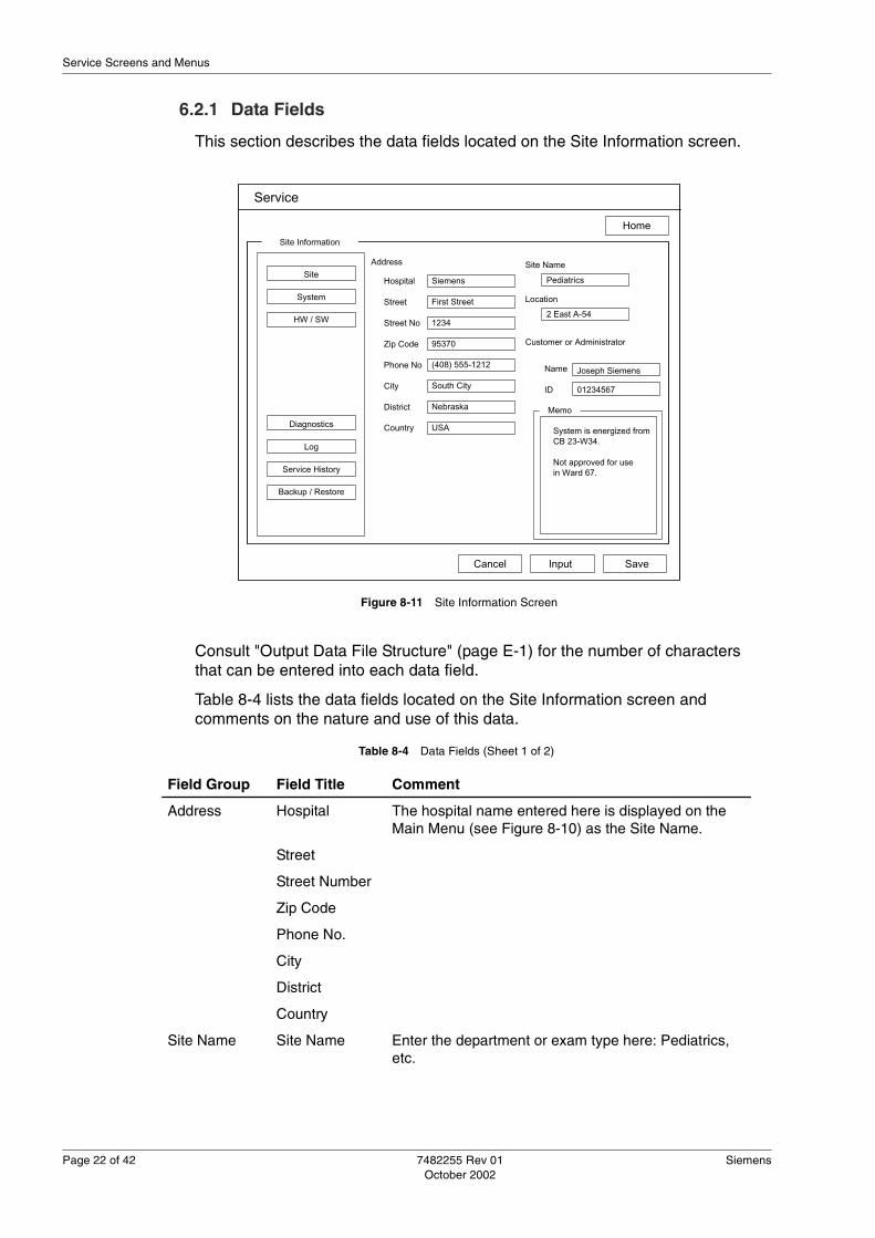
Page 22 of 42 7482255 Rev 01 Siemens October 2002
Service Screens and Menus
6.2.1 Data Fields
This section describes the data fields located on the Site Information screen.
Consult "Output Data File Structure" (page E-1) for the number of characters that can be entered into each data field.
Table 8-4 lists the data fields located on the Site Information screen and comments on the nature and use of this data.
Figure 8-11 Site Information Screen
Service
Home
Site
System
HW / SW
Diagnostics
Log
Service History
Backup / Restore
Site Information
InputCancel Save
Address
Hospital
Street
Street No
Zip Code
Phone No
City
District
Country
Site Name
Location
Customer or Administrator
Name
ID
Memo
Siemens
First Street
1234
95370
(408) 555-1212
South City
Nebraska
USA
Pediatrics
2 East A-54
Joseph Siemens
01234567
System is energized fromCB 23-W34.
Not approved for usein Ward 67.
Table 8-4 Data Fields (Sheet 1 of 2)
Field Group Field Title Comment
Address Hospital The hospital name entered here is displayed on the Main Menu (see Figure 8-10) as the Site Name.
Street
Street Number
Zip Code
Phone No.
City
District
Country
Site Name Site Name Enter the department or exam type here: Pediatrics, etc.

Siemens 7482255 Rev 01 Page 23 of 42October 2002
Chapter 8 - Software
6.2.2 Control Buttons
Three control buttons appear at the bottom of the Site Information screen: Input, Cancel, and Save; these control the editing of the data fields located on the screen.
� Input: Selecting the Input button allows the user to edit the data fields.
� Cancel: Selecting the Cancel button displays the message box shown in See “Cancel Message Box” on page 8-23. Select the OK button to re-dis-play the information saved in the system memory. Selecting the Cancel button, located in the cancel message box, returns the screen to the state that existed before the Cancel button was pressed.
� Save: Selecting the Save button displays the message, “Do you want to save changes?” After display of the message, selecting the OK button saves the data that is currently displayed in the data fields. Selecting the Cancel button, after display of this message, returns the screen to the state that existed before the Cancel button was pressed.
Location Location Enter the building or room number in which the system is located.
Customer or Administrator
Name Enter the name of the individual who is responsible for the system.
ID Enter the identity number of the responsible individual.
Memo Memo Enter additional information that must be associated with the system.
Table 8-4 Data Fields (Sheet 2 of 2)
Field Group Field Title Comment
Figure 8-12 Cancel Message Box
X
Ok Cancel
Cancel
Do you want to revert to saved data?
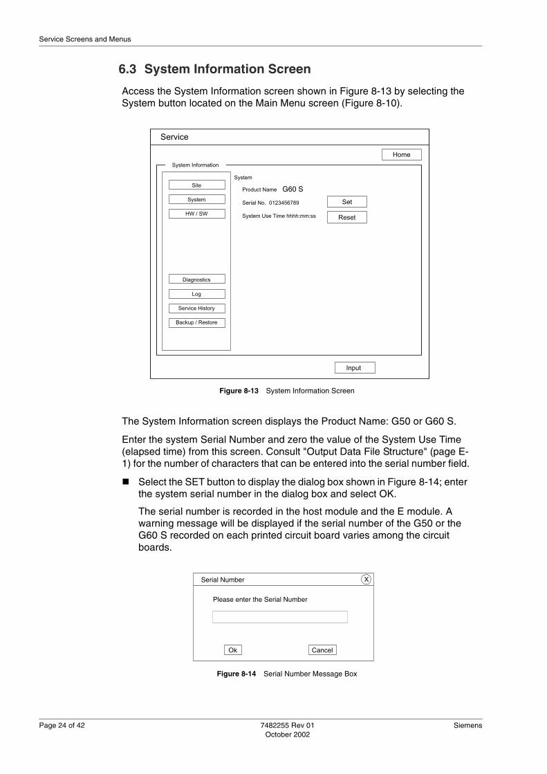
Page 24 of 42 7482255 Rev 01 Siemens October 2002
Service Screens and Menus
6.3 System Information Screen
Access the System Information screen shown in Figure 8-13 by selecting the System button located on the Main Menu screen (Figure 8-10).
The System Information screen displays the Product Name: G50 or G60 S.
Enter the system Serial Number and zero the value of the System Use Time (elapsed time) from this screen. Consult "Output Data File Structure" (page E-1) for the number of characters that can be entered into the serial number field.
� Select the SET button to display the dialog box shown in Figure 8-14; enter the system serial number in the dialog box and select OK.
The serial number is recorded in the host module and the E module. A warning message will be displayed if the serial number of the G50 or the G60 S recorded on each printed circuit board varies among the circuit boards.
Figure 8-13 System Information Screen
Service
Home
Site
System
HW / SW
Diagnostics
Log
Service History
Backup / Restore
System Information
Input
System
Product Name Omnia-X
Serial No. 0123456789
System Use Time hhhh:mm:ss
Set
Reset
G60 S
Figure 8-14 Serial Number Message Box
X
Ok Cancel
Serial Number
Please enter the Serial Number

Siemens 7482255 Rev 01 Page 25 of 42October 2002
Chapter 8 - Software
� Select the Reset button to display a dialog box that allows the zeroing of the elapsed time displayed in the System Use Time field.
6.4 System Configuration Screen for Hardware
Select the HW/SW button located on the Main Menu screen (Figure 8-10) to display the System Configuration screen for hardware, software, and peripherals shown in Figure 8-15.
Select the radio button labeled Hardware that is located on the right side of the System Configuration screen to display the System Configuration for Hardware screen.
The System Configuration Hardware screen displays the data values recorded in an EEPROM located on each assembly: Assy Name and AS No.
6.5 System Configuration Screen for Software
Select the HW/SW button located on the Main Menu screen (Figure 8-10) to display the System Configuration screen for hardware, software, and peripherals shown in Figure 8-15.
Select the radio button labeled Software that is located on the right side of the System Configuration screen to display the System Configuration Software screen.
Figure 8-15 System Configuration Screen for Hardware
Service
Home
Site
System
HW / SW
Diagnostics
Log
Service History
Backup / Restore
System Configuration - Hardware
Assy No. Assy Name AS No Hardware
Software
Peripheral
A30 ECGX 2
A36 PSEL 1A36-2 A3RD 0A40 STRX 3A42 TXBF 1A44 STRX 0A46 RXBFA 1A46 RXBFB 1A48 BWPP 0A50 SUBC 1A51 CMEM(B)63 1A51 CMEM(V)63 1A56 CFPR 3A56-1 DPPR 2A66 DTPS 1
A70 DVSC 1A72 BPVM 2

Page 26 of 42 7482255 Rev 01 Siemens October 2002
Service Screens and Menus
The System Configuration Software screen displays the installed software applications according to the name, sub-name, and build or version number of each application.
The list includes software options installed in the Preset, listing these software options as Option in the sub-name column and representing their versions as a hyphen.
If the complete list of the software applications cannot be displayed on this screen, a scroll bar appears to the right of the screen. Use the scroll bar to view the complete list of installed software.
6.6 System Configuration Screen for Peripherals
Access the System Configuration screen shown in Figure 8-15 by selecting the HW/SW button located on the Main Menu screen (Figure 8-10).
Select the radio button labeled Peripheral that is located on the right side of the System Configuration screen to display the System Configuration Peripheral screen.
Ten data rows are provided on this screen for recording the Equipment Name / Memo for the peripherals installed on the system.
Figure 8-16 System Configuration Screen for Software
Service
Home
Site
System
HW / SW
Diagnostics
Log
Service History
Backup / Restore
System Configuration - Software
No. NAME Sub Name Build / Ver. No. Hardware
Software
Peripheral
1 OS Windows CE 3.00
2 Omnia-X Omnia-X 1.0.000
3 TDI Option -
4 TDI Option -

Siemens 7482255 Rev 01 Page 27 of 42October 2002
Chapter 8 - Software
Select the Input button to enable editing of the data fields. After entering data or editing the data fields, select the Save button to record the new data. Select the Cancel button to display the message box shown in Figure 8-12; select the OK button on this message box to cancel new data and to re-display the previously existing data.
6.7 Transducer Screen
Access the Transducer screen shown in Figure 8-18 by selecting the Transducer button located on the Main Menu screen (Figure 8-10).
The Transducer screen lists the names of available transducers by the Transducer Name and the Transducer ID number.
Figure 8-17 System Configuration for Peripheral
Service
Home
Site
System
HW / SW
Diagnostics
Log
Service History
Backup / Restore
System Configuration - Peripheral
No. Equipment Name / Memo Hardware
Software
Peripheral
1
2
3
4
5
6
7
8
9
10
Modem Siemens M12 28 / 2 / 2000 31 / 4 / 2001
Cancel Input Save

Page 28 of 42 7482255 Rev 01 Siemens October 2002
Service Screens and Menus
Figure 8-18 Transducer Information Screen
Service
Home
Site
System
HW / SW
Diagnostics
Log
Service History
Backup / Restore
Transducer
Probe Name Probe ID
7L40+ 2055C50+ 2083C40+ 2106EV+ 211P4-2 212C8-5 237

Siemens 7482255 Rev 01 Page 29 of 42October 2002
Chapter 8 - Software
6.8 Diagnostics Screen
Access the Diagnostics screen shown in Figure 8-19 by selecting the Diagnostics button located on the Main Menu screen (Figure 8-10).
On the Diagnostics screen, check boxes arranged according to hierarchy levels are displayed adjacent to related test targets. Checking the box adjacent to the All Packages label will enable testing of all packages. Checking a box in the next lower hierarchy will remove the check mark from the All Packages target and enable testing of all of the targets in the hierarchy that is located below that checked target. Placing a check in a single box located at the lowest hierarchy will cause only that target to be tested.
When check marks have been entered in the boxes for the targets that are to be tested, select the Execution button to test the selected targets. When the pattern check for the host module, E module, or the DIMAQ-IP is performed, power down the system and re-energize it to reboot the software.
Observe the monitor as the testing progresses; pass–fail results will be displayed in the window located to the right of the diagnostic list.
See "Diagnostic Messages" (page 6-3) for information on the messages. To determine which spare part contains a failed component cited in the diagnostic message, see "Component Designations" (page F-1); "Spare Parts" (page C-1) lists the spare parts.
Figure 8-19 Diagnostics Screen
Service
Home
Site
System
HW / SW
Diagnostics
Log
Service History
Backup / Restore
Diagnostics
Execution
HostBox Fail: Test #1 ErroAll Packages
Host Module Package
Pattern Check
Host Module
E Module Package
Pattern Check
E Module
IPPC Pattern Check
Operator
Power Box

Page 30 of 42 7482255 Rev 01 Siemens October 2002
Service Screens and Menus
6.9 Log Screen
Access the Log screen shown in Figure 8-20 by selecting the Log button located on the Main Menu screen (Figure 8-10).
This screen displays buttons that allow access to the Key History Log and Error Log screens that are discussed in the following sections:
� "Key History Log Screen" (page 8-30)
� "Error Log Screen" (page 8-32)
6.9.1 Key History Log Screen
Select the Key History Log button located on the Log screen (Figure 8-20) to display the Key History Log screen shown in Figure 8-22.
Figure 8-20 Log Screen
Service
Home
Site
System
HW / SW
Diagnostics
Log
Service History
Backup / Restore
LogSystem Status
Key History Log
Error Log

Siemens 7482255 Rev 01 Page 31 of 42October 2002
Chapter 8 - Software
The Key History Log screen displays a record of the most recent 512 keyboard, trackball, and system events. The most recent events appear at the top of the log screen, arranged in descending chronological order. The events logged in this screen are recorded according to the formats presented in Table 8-5.
Two keys are located on the Key History Log screen:
� The Clear key initiates the deletion of the Key History Log data and dis-plays a confirmation dialog box shown Figure 8-21; confirm by selecting the OK button or cancel the deletion of the log data by selecting the Cancel button (Figure 8-21).
Table 8-5 Key History Log Formats
Event Record Format Comment
System Power On Time (HH:MM:SS) Start Up
QWERTY Key Stroke Time (HH:MM:SS) KBD (Key) Keys A – Z, 0 – 9
Function Key Stroke Time (HH:MM:SS) (Key Name)
Trackball Time (HH:MM:SS) TRACKBAL Only first trackball event in the series is logged
STC STC events are not logged
Figure 8-21 Clear Logged Data Message Box
X
Ok Cancel
Clear
Do you want to delete the logged data?

Page 32 of 42 7482255 Rev 01 Siemens October 2002
Service Screens and Menus
� The Back key returns to the Log screen (Figure 8-20).
6.9.2 Error Log Screen
Select the Error Log button located on the Log screen (Figure 8-20) to display the Error Log screen shown in Figure 8-23.
The Error Log screen displays the 100 most recent error messages in descending chronological order. The error messages include those occurring during system startup, those generated during diagnostic testing (Figure 8-19), and safety errors, such as the TEE transducer over-temperature. Multiple malfunctions of the same type are logged as individual errors.
Components that are not spare parts, but which are contained inside a spare part, can be cited in the error log. See Table F-1 of "Component Designations" (page F-1) to determine which spare part contains the component cited in an error log; see "Spare Parts" (page C-1) for a listing of the system spare parts.
Each error is logged according to the date, time, status (circumstances), and includes details of the malfunction. The format of the data output is discussed in "Output Data File Structure" (page E-1).
Two keys are located on the Error Log screen:
� The Clear key initiates the deletion of the Error Log data and displays a confirmation message box (see Figure 8-21); confirm or cancel the deletion of the error log data in this message box.
Figure 8-22 Key History Log Screen
Service
Home
Key History Log
Clear
Time
BACK
Key
17:50:26 SET17:50:24 TRACKBAL17:50:21 Preset17:50:16 TRACKBAL17:45:53 Review17:45:43 IPC Disk17:45:29 Video IO17:42:23 Power17:42:18 Power17:41:38 Freeze17:41:23 Depth(E)17:41:22 Depth SW17:40:30 B SW

Siemens 7482255 Rev 01 Page 33 of 42October 2002
Chapter 8 - Software
� The Back key returns to the Log screen (Figure 8-20).
6.10 Service History Screen
Access the Service History screen shown in Figure 8-24 by selecting the Service History button located on the Main Menu screen (Figure 8-10).
Use this screen to review previously recorded service activities and to record completed or on-going service activities.
Figure 8-23 Error Log Screen
Service
Home
Error Log
Clear
Date
BACK
Time
08/25/00 14:24:05 Diagnosis #80002000 = 2308/25/00 14:05:21 Operation TEE Temp08/25/00 09:05:12 Startup Voltage Power Error08/24/00 14:24:05 Diagnosis #80002000 = 2308/24/00 14:05:21 Operation TEE Temp08/20/00 09:05:33 Diagnosis #80002000 = 2308/17/00 14:24:05 Operation TEE Temp08/17/00 14:20:15 Startup Voltage Power Error08/16/00 15:24:45 Operation TEE Temp08/16/00 14:24:05 Diagnosis #80002000 = 2308/15/00 14:05:25 Operation TEE Temp08/14/00 09:05:04 Startup Voltage Power Error08/13/00 14:44:33 Operation TEE Temp08/12/00 14:42:05 Diagnosis #80002000 = 2308/11/00 14:24:05 Operation TEE Temp08/10/00 14:05:05 Diagnosis #80002000 = 23
Status Detail

Page 34 of 42 7482255 Rev 01 Siemens October 2002
Service Screens and Menus
The display of the Service History screen is configured for service data entry (Figure 8-24) when it opens; the History List field displays Today and the Date of Service field displays the present date. The Service Engineer Name remains blank and each of the service category keys displays an initial default.
6.10.1 Viewing Service Records
Service activities are recorded and recalled according to the date entered in the Date of Service field. Once entered, the date of service is listed in the drop-down History List combo box. To view a service record, open the drop-down History List combo box and select the date of the service; select the View button located at the bottom of the screen to display the key and memo data recorded for the service activity performed on that date.
View the fields located below the History List to rapidly determine if the displayed record is the record that you wish to review. See "Field Descriptions" (page 8-35) for a description of the Key fields.
6.10.2 Recording Service Activities
Each service record allows the service engineer to enter key data in the fields labeled Key 1 through Key 5. These key field entries can be used to categorize the nature of the service activity for rapid review in the future.
Figure 8-24 Service History Screen
Service
Home
Site
System
HW / SW
Diagnostics
Log
Service History
Backup / Restore
Service History
InputView Save
MemoToday
Select
Select
Select
Select
Select
DD / MM / YYYY
History List
Date of Service
Service Engineer Name
Key 1
Key 2
Key 3
Key 4
Key 5

Siemens 7482255 Rev 01 Page 35 of 42October 2002
Chapter 8 - Software
Use the following steps to enter service records:
1. Open the Service History screen by selecting the Service History button located on the Main Menu screen (Figure 8-10).
2. Verify that Today is displayed in the History List field and that the current date is displayed in the Date of Service field.
3. Select the Input button located at the bottom of the screen to enable data entry.
4. Enter the name of the service engineer in the Service Engineer Name field.
5. Enter the key field data: See "Field Descriptions" (page 8-35).
6. Enter the Memo field information: "Field Descriptions" (page 8-35).
7. Select the Save button located at the bottom of the screen to record the data.
6.10.3 Editing Existing Service Records
Existing service records can be edited by combining the two procedures listed above: "Viewing Service Records" (page 8-34) and "Recording Service Activities" (page 8-34).
Perform the following steps to edit an existing record:
1. Select the date of the recorded service activity in the History List.
2. Select the View button to display the record for that date.
3. Select the Input button to enable editing of the displayed data.
4. Edit the data: See "Field Descriptions" (page 8-35).
5. After completing the editing of the data, select the Save button to record the new data.
6.10.4 Field Descriptions
The Service History screen contains 9 fields that are used to categorize and summarize each recorded service activity. This section describes the use of each of these fields.
� The History List contains the Date of Service recorded for each service activity. Selecting a date from this drop-down combo box, and then select-ing the View button, will display the data recorded for that service activity.
Note: The Save button causes the currently displayed data to be recorded. Data that has been edited, on screens that are not currently displayed, will not be saved. When entering or editing several service records, select the Save button before moving to the next service record.
Note: The Save button causes the currently displayed data to be recorded. Data that has been edited, on screens that are not currently displayed, will not be saved. When entering or editing several service records, select the Save button before moving to the next service record.

Page 36 of 42 7482255 Rev 01 Siemens October 2002
Service Screens and Menus
� The Date of Service field allows entry of the date of a specific service record. Once the service record is saved, this date appears in the History List and can be selected to recall the information recorded for that service activity.
� The Service Engineer Name field allows the entry of the name of the indi-vidual who performed the service activity. This name entered here appears in this field when a record is viewed.
� The Key 1 field allows categorization of the service task according to the type of maintenance performed. The categories of Preventive Mainte-nance, Corrective Maintenance, and -blank- are available for selection in the drop-down combo box; other categories can be entered from the key-board after selecting -blank- from the list.
� The Key 2 field allows identification of the devices maintained during this service activity. The devices of Sys. Hardware, Sys. Software, Sys. Hard & Soft, Transducer, Option Device, No Problem Found, -blank-, and Other are available for selection in the drop-down combo box; other devices can be entered from the keyboard after selecting -blank- from the list.
� The Key 3 field allows the categorization of the service activity according to the frequency of its occurrence. The entries of Reappears (Always), Reap-pears (Sometimes), Reappears (Rarely), No Reappearance, Other or -blank- are available for selection in the drop-down combo box; other fre-quencies can be entered from the keyboard after selecting -blank- from the list.
� The Key 4 field allows the service task to be categorized according to sta-tus. The status categories of Completion, Observing for reappearance, Waiting for spare part, Other, and -blank- are available for selection in the drop-down combo box; a different status can be entered from the keyboard after selecting -blank- from the list.
� The Key 5 field allows the service task to be categorized according to the time required to complete the task. The durations of Within 15 min, Within 30 min, Within 45 min, Within 1h, Within 1.5 h, Within 2 h or Over 2h are available for selection in the drop-down combo box; a different duration can be entered from the keyboard after selecting -blank- from the list.
� The Memo field allows entry of extended text comments.
6.11 Backup/Restore
Access the Backup/Restore screen shown in Figure 8-25 by selecting the Backup/Restore button located on the Main Menu screen of the service software (Figure 8-10).
Use the screen shown in Figure 8-25 to backup or restore the listed service data.
Note: A formatted MO diskette is required to perform the service data backup operation; for the restore operation, the backed-up service data must be avail-able on an MO diskette.

Siemens 7482255 Rev 01 Page 37 of 42October 2002
Chapter 8 - Software
6.11.1 Backing Up Service Data
Use the following procedure to backup the service data.
1. Open the Main Menu service screen and select the Backup / Restore but-ton (Figure 8-10).
2. Select the Backup radio button located at the top of the screen shown in Figure 8-25.
3. In the scrolling list, check the box adjacent to the service data items to be backed up: Table 8-6 lists the options available for performing a complete or individual back up.
Figure 8-25 Backup/Restore Screen
Service
Home
Site
System
HW / SW
Diagnostics
Log
Service History
Short-cut Backup / Restore
Go
Command
Backup
Restore
Cancel
Packages
Estimated Execution Time: mm : ss
Progress Status Bar
Done!
0% 20% 40% 60% 80% 100%
All Packages Service Information - Site Information - System Information - Hardware Information - Software Information - Peripheral
Table 8-6 Service Data Backup Hierarchy (Sheet 1 of 2)
Top Level Sub Category
Individual Packages Comment
All Packages All service data packages
Service All service data
Site Information Site only
System Information System only
Hardware Information Hardware only
Software Information Service data only

Page 38 of 42 7482255 Rev 01 Siemens October 2002
Service Screens and Menus
4. Insert an MO diskette in the MO drive and select the Go button located at the bottom of the screen to begin the backup.
5. When the message box shown in Figure 8-26 is displayed, select the Ok button to format the diskette; the backup will continue.
6. The message box shown in Figure 8-27 will be displayed; accept the backup name provided or enter a different name and select OK to continue the backup operation.
Peripheral Information Peripheral only
Diagnostics Diagnostics only
Service History Service History only
Key History Log Key History Log only
Table 8-6 Service Data Backup Hierarchy (Sheet 2 of 2)
Top Level Sub Category
Individual Packages Comment
� Caution: Existing data on the MO diskette will be erased automatically during the formatting of the diskette, before the backup data is written to the MO dis-kette.
Figure 8-26 Disk Format Message box
X
Ok Cancel
Service
Formatting will erase all [data] from the disk.
Do you want to format disk?
Figure 8-27 Name the Backup Message Box
Note: The system software assigns a name for the backup file, using the follow-ing date format: YYYYMMDDHHMMSS.
X
Ok Cancel
Service
Backup

Siemens 7482255 Rev 01 Page 39 of 42October 2002
Chapter 8 - Software
7. When the progress bar located on the Backup / Restore screen reaches 100% a Done message will be displayed: Remove the MO disk and label it.
6.11.2 Restoring Service Data
1. Select the Restore radio button located at the top of the screen; in the scrolling list, check the box adjacent to the service data items to be restored.
2. Insert the MO disk that contains the appropriate backup into the MO drive.
3. Select the Go button located at the bottom of the screen to begin the restore process.
The restoration process does not allow the user to select individual packages for restoration. The broader categories available for restoration are listed in Table 8-7.
6.12 Imaging Test Pattern
Access the Imaging Test Pattern screen shown in Figure 8-28 by selecting the Imaging Test Pattern button located on the Main Menu screen (Figure 8-10).
To display a test image, select the appropriate button located on this screen. When a test image is displayed, select the Next key to return to the Imaging Test Pattern screen.
Adjust the VCR, VTR, and the monitor while displaying the test images accessed from this screen:
� Black and White Test Pattern: See Figure 8-29
� Framing and Black and White Grayscale Pattern: See Figure 8-30
� Color Bar Pattern: See Figure 8-31
� Caution: Selecting the Cancel button during an incomplete service data restore procedure will leave the system inoperable: Do no select the Cancel button when restoring service data.
Table 8-7 Service Data Restore Hierarchy
Top Level Individual Packages Comment
Service All service data
Site Information Site only
Peripheral Information Peripheral only
Service History Service History only
Note: Terminate the display of a test pattern by pressing SET.

Page 40 of 42 7482255 Rev 01 Siemens October 2002
Service Screens and Menus
� Color Scale Pattern: See Figure 8-32
Figure 8-28 Imaging Test Pattern Utilities
B & W Pattern
Service
Home
Site
System
HW / SW
Diagnostics
Log
Service History
Backup / Restore
Utilities - Imaging Test Pattern
Color Bar Pattern
Color Scale Pattern
FramingB & W Gray Scale Pattern
Figure 8-29 Black and White Test Pattern

Siemens 7482255 Rev 01 Page 41 of 42October 2002
Chapter 8 - Software
Figure 8-30 Grayscale and Framing Pattern
Figure 8-31 Color Bar Pattern

Page 42 of 42 7482255 Rev 01 Siemens October 2002
Service Screens and Menus
Figure 8-32 Color Scale Pattern

Siemens 7482255 Rev 01 Page 1 of 8October 2002
Chapter 9 - Planned Maintenance
Chapter 9: Planned MaintenanceThis chapter provides information on the planned maintenance for the G50 and the G60 S.
The following topics are presented in this chapter:
1.0 Introduction ...................................................................................9-2
2.0 Required Tools and Documents ....................................................9-2
3.0 Required Materials ........................................................................9-2
4.0 Preparations .................................................................................9-3
5.0 Cleaning the System .....................................................................9-3
6.0 Cleaning Subsystems ...................................................................9-3
7.0 Cleaning and Inspecting Transducers ..........................................9-4
8.0 Safety Checks ...............................................................................9-5
9.0 System Test ..................................................................................9-6
10.0 Concluding the Maintenance ......................................................9-7

Page 2 of 8 7482255 Rev 01 Siemens October 2002
Introduction
1.0 IntroductionPlanned maintenance is recurring and must be performed at least every 12 months. Planned maintenance includes visual inspections, safety testing, cleaning, and functional performance checks of the system and its equipment.
Print the maintenance report contained in the appendix, "Maintenance Report" (page G-1). Enter the data in the report as the planned maintenance is performed. A copy of the completed maintenance report must be provided to the customer and to the regional service office, as appropriate to the region.
Some regions require planned maintenance more frequently. It is the responsibility of the customer service engineer (CSE) to be aware of, and adhere to, all local regulations regarding planned maintenance intervals for this system and its equipment.
If a test fails on a system covered by a full service contract, repair the defect and repeat the check. If the system passes the test after being repaired, record that the system passed the test.
If a test fails on a system not covered by a full service contract, obtain approval from the customer to repair the defect. Repeat the test on the repaired system, and record that the system passed the test. If the customer does not want you to repair the defect, record that the system failed the test, and note this failure in the open issues section of the maintenance report.
2.0 Required Tools and DocumentsUse the following tools to perform the procedures described in this chapter.
� Standard field service tools
� MO diskette
� Electrical safety analyzer
� Ground resistance meter
� Transducer
� The Field Electrical Safety Test Procedure (p/n 7482776), the G50 and G60 S Electrical Safety Test Limits (p/n 7482784), and the Field Electrical Safety Test Report (p/n 7482768) are used during the planned mainte-nance procedure.
3.0 Required Materials Transmission gel is required to perform the testing and maintenance specified in this chapter.
Note: Always keep a copy of completed maintenance reports for your own records.

Siemens 7482255 Rev 01 Page 3 of 8October 2002
Chapter 9 - Planned Maintenance
4.0 Preparations Perform the following preparations before beginning the maintenance routines.
1. Discuss the system performance with the customer; determine what con-cerns the customer might have regarding the system performance.
2. In the maintenance report, record the information obtained from the cus-tomer, and the actions taken to resolve these concerns.
3. Save the system preset data on an MO diskette.
4. Turn off the system and disconnect the power cable from the external power source.
5.0 Cleaning the System Use a soft cloth, lightly moistened with a mild soap solution, to clean the surface of the system, including the system control panel, transducer holders, system side panels, and any on-board OEM peripheral devices. Refer to the operating instructions for additional information on cleaning the system, transducers, and filters.
6.0 Cleaning SubsystemsClean the following subsystems:
1. On each side of the system, remove the air filter retainer (2 total) as indi-cated in Figure 9-1.
�Warning: When handling parts that may have had patient contact, take appropriate precau-tions against exposure to blood borne pathogens.
� Caution: Do not use alcohol, other organic solvents, or cleansing agents that contain alcohol or organic solvents to clean the G60 S.
Figure 9-1 Air Filter Removal

Page 4 of 8 7482255 Rev 01 Siemens October 2002
Cleaning and Inspecting Transducers
2. Remove the two air filters and wash them in water.
3. Allow the filters to dry and re-install them in the G60 S.
4. Remove the trackball bezel, shown in Figure 9-2.
5. Remove the ball from the trackball assembly.
6. Wipe the ball with isopropyl alcohol and a tissue.
7. Use a cotton swab and isopropyl alcohol to clean the inside of the trackball assembly; clean the surfaces of the idler wheel and encoders thoroughly.
8. Allow the ball and the trackball assembly to dry.
9. Reinstall the ball in the assembly and install the bezel.
7.0 Cleaning and Inspecting Transducers Clean each transducer with a soft cloth dampened with a mild soap solution.
� Caution: Verify that the filter elements are completely dry before re-installing them in the G50 or the G60 S. Moisture retained by a filter can damage the power supply.
Figure 9-2 External and Internal Views of the Trackball
� Caution: Do not allow foreign objects or debris to fall into in the trackball assem-bly. The presence of foreign matter in the trackball assembly can obstruct the operation of the trackball.
Bezel
Trackball
IdlerWheel
X and Y Encoders
� Caution: Do not clean the transducer head with isopropyl alcohol or other organic solvents. Do not allow the transducer cable and connector to become wet when cleaning them with mild soap and water.
Note: Consult the Operating Instructions [kit] for the G50 and the G60 S for addi-tional information on transducers: Instructions for Use, System Reference, and the Transducer Reference.

Siemens 7482255 Rev 01 Page 5 of 8October 2002
Chapter 9 - Planned Maintenance
Inspect all of the transducers for physical damage such as cracks, air bubbles (sector transducers), or other defects that may affect the performance of the transducer: See IEC 60601-2-18.
Remove from service, all transducers that are cracked, punctured, discolored, or which have a frayed or cracked cable.
Inspect the transducer cable and the cable connections at the strain reliefs located on both ends of the cable. Inspect all transducers and user accessible ports for damage, loose connectors, and bent pins.
8.0 Safety Checks Perform the following safety inspection and test routines.
1. Turn off the system and disconnect the power cable from the main power source.
2. Inspect the wheels and wheel locks for damage, and test them to verify that the wheels and the wheel locks operate properly.
3. Verify that the monitor is securely mounted on the monitor arm, and that it can be turned and tilted easily.
4. Perform the Field Electrical Safety Test Procedure (p/n 7482776) using the G50 and G60 S Electrical Safety Test Limits (p/n 7482784); record the results of the safety test in the Field Electrical Safety Test Report (p/n 7482768).
5. After completion of the electrical safety test and the test report, provide the customer and the regional office with a copy of the report; retain a copy of the report for your personal records.
6. With the system turned off, verify that all components and subsystems are properly secured and that all cables are properly connected.
7. Verify that mandatory system modifications have been made.
� Caution: With two exceptions, a discolored transducer housing normally indi-cates a defective transducer. The use of the disinfectants Cidex OPA and Gigas-ept FF can discolor some transducer housings without affecting the operation of the transducer. Discolored transducers that have been disinfected with Cidex OPA and Gigasept FF can be considered usable.
� Caution: When the system is opened for service, sensitive components are exposed to possible damage by electrostatic discharge (ESD). Use ESD protec-tive methods and equipment to protect these sensitive components.

Page 6 of 8 7482255 Rev 01 Siemens October 2002
System Test
9.0 System Test Consult the Instructions for Use for information on the daily operational checklist.
1. Turn on the system and verify that the system performs a calibration with-out displaying an error message.
2. Check that an appropriate image and corresponding graphic overlay are displayed on the monitor (depends on the selected transducer and user presets).
3. Check the system time and date, and reset it if necessary.
4. Functionally test all operator controls and indicators, including the foot-switch (if installed), the alphanumeric keyboard, and the MO disk drive.
5. Always check the transducers, even if the customer has not signed a main-tenance contract for them. Replacement depends upon the type of mainte-nance contract.
6. For each transducer, verify that the transducer identification and operating frequency are correctly displayed when the transducer is connected.
7. Perform a scan on a phantom with each transducer, and evaluate the image quality.
• While scanning, flex the cable at the strain relief and verify that the image quality is not affected.
• Check array transducers for signs of dropout (dark columns emanating into the image).
• Check sector transducers for signs of image flickering.
8. Check the FREEZE function using all applicable transducers, the control panel, and the footswitch.
9. Always check peripheral devices (OEMs), even if the customer has not signed a maintenance contract for them. The check should also include cleaning and optimization of settings if necessary. Replacement depends upon the type of maintenance contract. For information about operating and cleaning of OEM peripheral devices, refer to the respective OEM oper-ating instructions.
10. Verify the operation of the Black and White Video Printer; freeze an image and perform a test print. If necessary, clean the print head and test the printer again. If necessary, optimize the printer settings according to the customer guidance. Refer to the OEM operating instructions for detailed information on optimizing printer settings.
11. Check any other installed OEMs. If necessary, clean the OEM, and opti-mize the settings.
12. Check system preset data, and restore from the disk if necessary.
13. Check the protective ground wire again. For detailed information refer to ARTD-002.731.17.01.02 (or newer).

Siemens 7482255 Rev 01 Page 7 of 8October 2002
Chapter 9 - Planned Maintenance
10.0 Concluding the Maintenance Discuss, with the customer, the maintenance findings noted in the maintenance report.
Give the customer the completed maintenance report, and return a copy to your regional service office, as appropriate to your region.
Note: Always keep a copy of the completed maintenance report for your own records.

Page 8 of 8 7482255 Rev 01 Siemens October 2002
Concluding the Maintenance

Siemens 7482255 Rev 01 Page 1 of 4October 2002
Appendix A - Installation Procedure
Appendix A: Installation ProcedureThis appendix provides instructions for the unpacking and installation of the G50 and the G60 S.
This section includes the following topics:
1.0 Unpacking the G50 and the G60 S ...............................................A-2
2.0 Installing the G50 or the G60 S ....................................................A-4

Page 2 of 4 7482255 Rev 01 Siemens October 2002
Unpacking the G50 and the G60 S
1.0 Unpacking the G50 and the G60 SFigure A-1 presents the packaging methods employed for the G50 and the G60 S.
1. Cut the shipping straps and tape that hold the external packaging in place.
2. Remove the three plastic clamps.
3. Open and remove the shipping box.
4. Remove the accessories box.
5. Remove the two cardboard ramp supports from under the system.
6. Place the ramp supports on the floor (items 7).
7. Lower the ramp (SLOPE) down onto the ramp supports (items 7).
8. Remove the wrapping from the system.
9. Unlock the wheels of the G50 or the G60 S as shown in Figure A-1.
10. Roll the ultrasound system off of the pallet.
11. Review the packing slip: Verify that all equipment and OEMs indicated on the packing slip are present.
12. Inspect all of the equipment and report any shipping damage immediately.
13. Verify that the serial numbers of the system, monitor, and options agree with those listed on the delivery note: Report discrepancies.
14. Unpack the accessories box before beginning the installation and verify that the following are present in the box:
• Power cord (1)
• Array transducer holder (4)
• Sector transducer holder (1)
• Gel bottle holder (1)
• System software MO diskette (1)
�Warning: The G50 and the G60 S weigh 130 kg (287 lb) and represents a lifting hazard; attempting to lift this system manually can cause serious injury. Instructions for lifting the G50 or the G60 S, when enclosed in its shipping container, are provided on the container. Once un-boxed from the shipping container, neither the G50 nor the G60 S is not designed for lifting; transport it on its casters.

Siemens 7482255 Rev 01 Page 3 of 4October 2002
Appendix A - Installation Procedure
Fig
ure
A-1
Pac
kagi
ng In
stru
ctio
nsF
or J
uly
Shi
pmen
ts

Page 4 of 4 7482255 Rev 01 Siemens October 2002
Installing the G50 or the G60 S
2.0 Installing the G50 or the G60 SUse the following instructions to install the ultrasound system at the customer site.
2.1 Tools Required
No special tools are required for this installation; only standard service tools are needed.
2.2 Documents Required
The Field Electrical Safety Test Procedure (p/n 7482776), the G50 and G60 S Electrical Safety Test Limits (p/n 7482784), and the Field Electrical Safety Test Report (p/n 7482768) are used during the installation procedure.
2.3 Preparation
Read this entire procedure before beginning an installation. Be prepared to submit an installation report as described in "Installation Report" (page B-1).
2.4 Installation
1. Unpack the system according to the guidelines provided in "Unpacking the G50 and the G60 S" (page A-2).
2. Test and verify the operation of the caster locking mechanism on all casters and the lock mechanism on the monitor arm.
3. Install the transducer and gel bottle holders.
4. Perform the system safety test according to "Safety Checks" (page 9-5).
5. Perform the Field Electrical Safety Test Procedure (p/n 7482776) using the G50 and G60 S Electrical Safety Test Limits (p/n 7482784); record the results of the safety test in the Field Electrical Safety Test Report (p/n 7482768).
6. After completion of the electrical safety test and the test report, provide the customer and the regional office with a copy of the report; retain a copy of the report for your personal records.
7. Perform the system operational test according to "System Test" (page 9-6).
8. After successful completion of the system test, submit an installation report according to the instructions provided in "Installation Report" (page B-1).
Note: Advise the customer to store the factory packaging materials for later use.

Siemens 7482255 Rev 01 Page 1 of 2October 2002
Appendix B - Installation Report
Appendix B: Installation ReportConsult the Siemens Speed Info 001/2001/US for information on completing the Ultrasound System Installation Report (7295749) shown in Figure B-1.
Access Speed Infos on the intranet at: http://www-td.med.siemens.de:88/. From this intranet page, select the following menu items to view SI 001/2001/US:
Product Information → US Systems → Speed Infos US → 2001 → 001/2001/US
During the installation, perform the Field Electrical Safety Test Procedure (p/n 7482776) using the G50 and G60 S Electrical Safety Test Limits (p/n 7482784); record the results of the safety test in the Field Electrical Safety Test Report (p/n 7482768).
After completion of the electrical safety test and the test report, provide the customer and the regional office with a copy of the report; retain a copy of the report for your personal records.
Note: The Ultrasound System Installation Report presented in Figure B-1 includes instructions for its completion and submission. Submit the report within 5 working days after completing the installation activity.

Page 2 of 2 7482255 Rev 01 Siemens October 2002
Figure B-1 Installation Report Form

Siemens 7482255 Rev 01 Page 1 of 18October 2002
Appendix C - Spare Parts
Appendix C: Spare PartsAt the time of the initial release of the G50 and the G60 S, it is likely that the Spare Parts Catalog (SPC) located on the intranet will not have been completed for these systems. For this reason, an interim spare parts list for both systems is included in this appendix.
See "Component Designations" (page F-1) to determine which module contains a component that is listed in an error log. Error logs are discussed in "Error Log Screen" (page 8-32).
This appendix contains the following sections:
1.0 G50 and G60 S Spare Parts .........................................................C-2
2.0 G50 and the G60 S Common Parts Photographs .........................C-5
3.0 G50 Spare Parts Photographs ......................................................C-11
4.0 G60 S Spare Parts Photographs ...................................................C-15
Note: The photographs included in section 4, G60 S Spare Parts Photographs, show spare parts for the G60 S. In most cases, there are only minor differences in the appearance of the comparable spare part for the G50 system.

Page 2 of 18 7482255 Rev 01 Siemens October 2002
G50 and G60 S Spare Parts
1.0 G50 and G60 S Spare PartsTable C-1 lists the spare parts for the G50 and G60 S. Some parts are common to both systems and are designated in the Description column. See Table 1-3 in "Introduction and System Requirements" (page 1-1) for information on the transducers supported by each system.
Table C-1 Spare Parts for the G50 and the G60 S
Description Part Number Photo and Comments
7.5L70 Exchange Transducer 5726534 See Table 1-3 for transducers
A03 PWR Switching Reg, Assy, G50/G60 S 7478824 Figure C-6; includes A07 PDSD
A05 Line Filter, module, 100V, G50/G60 S 7478816 Figure C-7
A05 Line Filter, module, 115V, G50/G60 S 7478790 Figure C-7
A05 Line Filter, module, 230V, G50/G60 S 7478808 Figure C-7
A07-1 XDST pcb, G50/G60 S 7473122 Figure C-8; Includes PCB, fuses, and outlet box
A10, CP Controller, G50/G60 S 7482057 Figure C-9; cables not included
A21 Battery Pack, G50/G60 S 7479087
A36-2 Third Array Port, G50/G60 S 7840221
A70-2, PPCL PCB, G50/G60 S 7479913
Air Filter, G50/G60 S 7478923 Figure C-4
C5-2 Exchange Transducer 7291961 See Table 1-3 for transducers
C6-2 Exchange Transducer 7472702 See Table 1-3 for transducers
C6-2 Transducer, JPN 7482537 See Table 1-3 for transducers
Cable hanger, Front, G50/G60 S 7479020 Figure C-3, Figure C-4
Cable hanger, Side, G50 7478022 Figure C-16, Figure C-18
Cable hanger, Side, G60 S 7479012 Figure C-24
Cable, Power cord, 100V, G50/G60 S 7478956
Cable, Power cord, 115V, G50/G60 S 7478949
Cable, Power cord, 230V, G50/G60 S 7478931
Caster, G50 7477966 Figure C-19, Figure C-15
Caster, G60 S 7478832 Figure C-24
CD, DIMAQ-IP SW 1.023, G50/G60 S 7482610
CD, DIMAQ-IP SW 1.2, G50/G60 S 7483576 Contained in v1.2 software upgrade kit
CP900, Color Printer NTSC, G50/G60 S 7473163 Figure C-1
CP900, Color Printer PAL, G50/G60 S 7473155 Figure C-1
CW2 Transducer 7472744 See Table 1-3 for transducers
DIMAQ-IP Module, Exchange G50/G60 S 7478683 Figure C-11; IPPC
E module, LC, G50 7477958 Figure C-15
E module, MS, G60 S 7482073 Figure C-26

Siemens 7482255 Rev 01 Page 3 of 18October 2002
Appendix C - Spare Parts
EC9-4 Transducer 7475747 See Table 1-3 for transducers
ECG, Assy, G50/G60 S 7482065 Figure C-10
EM Fan, single, G50/G60 S 7478741
EV9-4 Exchange Transducer 7472736 See Table 1-3 for transducers
EV9-4 Transducer, JPN 7482545 See Table 1-3 for transducers
Front Panel, G50/G60 S 7478881 Figure C-3
Fuses, 4.0A, G50/G60 S 7478782 Figure C-8
Fuses, 6.3A, G50/G60 S 7478774 Figure C-8
Host Module, G50 7477941
Host Module, G60 S 7473171 Figure C-25; Includes EMI shield
Ink Cassette, CP900, G50/G60 S 7479095
Keyboard, Assy, G50 7477933 Figure C-21, Figure C-15; includes slides
Keyboard, Assy, G60 S 7478717 Figure C-27, Figure C-22; includes slides
L10-5 Exchange Transducer 7472678 See Table 1-3 for transducers
L10-5 Transducer, JPN 7482529 See Table 1-3 for transducers
Left Bottom Cover, G50/G60 S 7473130 Figure C-5
Left Bumper Cover, G50/G60 S 7477354 Figure C-5
Left Caster Bumper Cover, G50/G60 S 7479921 Figure C-2
Leftside Panel, G50 7477982 Figure C-17, Figure C-5
Leftside Panel, G60 S 7478865 Figure C-23
Main Control Panel, Lower, Assy, G50/G60 S 7478691 Figure C-12; includes cable,Figure C-4, Figure C-5
MO disk, Replacement 1.0 SW, G50/G60 S 7473189 Software
MO disk, Replacement 1.2 SW, G50/G60 S 7477974 Software
MO Drive, G50/G60 S 5935031 Figure C-5
MO Fan, G50/G60 S 7478766
Monitor Color SVGA, 15 inch, G50/G60 S 7475101 Figure C-13, Figure C-2
Monitor Post Cover, G50 7478014 Figure C-16, Figure C-18
Monitor Post Cover, G60 S 7478915 Figure C-23
OEM bay, Top Shelf, G50/G60 S 7478840 Figure C-4
OEM Lower bay, Rear Cover, G50/G60 S 7478857
Overlay English, G50/G60 S 7479038 Figure C-3
Overlay German, G50/G60 S 7479046 Figure C-3
Overlay French, G50/G60 S 7479053 Figure C-3
Table C-1 Spare Parts for the G50 and the G60 S
Description Part Number Photo and Comments

Page 4 of 18 7482255 Rev 01 Siemens October 2002
G50 and G60 S Spare Parts
Overlay Spanish, G50/G60 S 7479061 Figure C-3
Overlay Italian, G50/G60 S 7479079 Figure C-3
P4-2 Exchange Transducer 4835232 See Table 1-3 for transducers
P4-2 Transducer, JPN 7482511 See Table 1-3 for transducers
P91 Printer, G50/G60 S 4835265 Figure C-1, Figure C-2
Plug, Gel Bottle, G50/G60 S 7292415
Probe Holders Short, G50/G60 S 7478972 Figure C-4
Probe holders, Univ, Long, G50/G60 S 7292084 Figure C-2
PWR Switching Reg Fan, single, G50/G60 S 7478758
Rear Panel, Lower, G50 7478006 Figure C-16, Figure C-18
Rear Panel, Lower, G60 S 7478907 Figure C-23
Rear Panel, Upper, G50 7477990 Figure C-16, Figure C-18
Rear Panel, Upper, G60 S 7478899 Figure C-23
Right Bottom Cover, G50/G60 S 7473148 Figure C-4
Right Bumper Cover, G50/G60 S 7478600 Figure C-4
Right Caster Bumper Cover, G50/G60 S 7479939 Figure C-2
Right side Panel, G50/G60 S 7478873 Figure C-4
Sony SVO-3500 VCR, NTSC 7473213
Sony SVO-3500 VCR, PAL 7473205
Sub Control Panel, Upper, Assy, G50/G60 S 7478709 Figure C-4, Figure C-5
Trackball, G50/G60 S 7478725 Figure C-3
VCR Sony-9500MD 4515404-L0800
VCR Sony-9500MDP 4515396
VF13-5 Exchange Transducer 5727243 See Table 1-3 for transducers
Table C-1 Spare Parts for the G50 and the G60 S
Description Part Number Photo and Comments

Siemens 7482255 Rev 01 Page 5 of 18October 2002
Appendix C - Spare Parts
2.0 G50 and the G60 S Common Parts Photographs
The photos in this section show parts that are common to both the G50 and the G60 S. Figure C-1 shows the P91 printer and the CP900 printer.
Figure C-2, Figure C-3, Figure C-4, and Figure C-5 indicate the parts that are common to both the G50 and the G60 S. The G50 is shown in these photographs.
Figure C-1 P91 B/W Printer (Left) and CP900 Printer (Right)
7473163 NTSC7473155 PAL
4835265
Figure C-2 Rear View G50 Common Parts
Monitor 7475101
Probe Holder Long 7292084
Left Caster Bumper Cover 7479921(2 each)
Right Caster Bumper Cover 7479939 (2 each)

Page 6 of 18 7482255 Rev 01 Siemens October 2002
G50 and the G60 S Common Parts Photographs
Figure C-3 Front View G50 Common Parts
Figure C-4 Right Side View G50 Common Parts
Keyboard Overlays
Track Ball 7478725
Cable Hanger Front 7479020
Front Panel 7478881
Sub Control Panel 7478709Main Control Panel 7478691Probe Holder Short 7478972
OEM Bay Top Shelf 7478840
Right Side Panel 7478873
Cable Hanger Front 7479020
Right Bumper Cover 7478600Right Bottom Cover 7473148
Air Filter 7478923

Siemens 7482255 Rev 01 Page 7 of 18October 2002
Appendix C - Spare Parts
Figure C-6 shows the switching power regulator.
Figure C-5 Left Side View G50 Common Parts
Sub Control Panel 7478709MO Drive 5935031Main Control Panel 7478691
Left Side Panel 7477982
Left Bumper Cover 7477354
Left Bottom Cover 7473130
Figure C-6 07478824 A03 PWR Switching Reg, Assy, G50/G60 S

Page 8 of 18 7482255 Rev 01 Siemens October 2002
G50 and the G60 S Common Parts Photographs
Figure C-7 shows the 05 Line Filter; this component can be provided in 100V, 115V, and 230V.
Figure C-8 shows the A07-1 XDST module containing the power fuses.
Figure C-9 shows the control panel controller.
Figure C-7 07478816 (100V), 07478790 (115V) and 07478808 (230V)
Figure C-8 07473122 A07-1 XDST PCB, G50/G60 S (Fuses)
FuseFuse
Figure C-9 07482057 A10, CP Controller, G50/G60 S

Siemens 7482255 Rev 01 Page 9 of 18October 2002
Appendix C - Spare Parts
Figure C-10 shows the ECG assembly.
shows the DIMAQ-IP image processor module.
Figure C-12 shows the lower assembly of the main control panel.
Figure C-10 07482065 ECG, Assy, G50/G60 S
Figure C-11 07478683 Exchange, DIMAQ-IP, Module, G50/G60 S
Figure C-12 07478691 Main CP, Lower, Assy, G50/G60 S

Page 10 of 18 7482255 Rev 01 Siemens October 2002
G50 and the G60 S Common Parts Photographs
Figure C-13 shows the 15 inch color monitor.
Figure C-14 shows the sub control panel.
Figure C-13 07475101 OEM, Monitor Color SVGA, 15 inch, G50/G60 S
Figure C-14 07478709 Sub CP, Upper, Assy, G50/G60 S

Siemens 7482255 Rev 01 Page 11 of 18October 2002
Appendix C - Spare Parts
3.0 G50 Spare Parts PhotographsThe photographs in this section show spare parts for the G50 system.
Figure C-15, Figure C-16, Figure C-17, and Figure C-18 provide views of the complete G50 system.
Figure C-15 G50 Front View
Keyboard G50 7477933
LC, E Module G50 74779582 Ports Standard; Third Port Option ShownSee Figure C-20 for standard configuration
Caster G50 7477966

Page 12 of 18 7482255 Rev 01 Siemens October 2002
G50 Spare Parts Photographs
Figure C-16 G50 Rear View
Figure C-17 G50 Left Side View
Monitor Post Cover G50 7478014
Cable Hanger Side G50 7478022Rear Panel Upper G50 7477990
Rear Panel Lower G50 7478006
Left Side Panel G50 7477982

Siemens 7482255 Rev 01 Page 13 of 18October 2002
Appendix C - Spare Parts
Figure C-19 shows a caster for the G50.
Figure C-18 G50 Right Side View
Note: The photographs included in section 4, G60 S Spare Parts Photographs, show spare parts for the G60 S. In most cases, there are only minor differences in the appearance of the comparable spare part for the G50 system.
Monitor Post Cover G50 7478014
Rear Panel Upper G50 7477990Cable Hanger Side G50 7478022
Rear Panel Lower G50 7478006
Figure C-19 7477966 G50 Caster

Page 14 of 18 7482255 Rev 01 Siemens October 2002
G50 Spare Parts Photographs
Figure C-20 shows the front of the E module for the G50, with the system covers installed.
Figure C-21 shows the G50 keyboard.
Figure C-20 G50 E Module (Front View with Cover Installed)
Figure C-21 7477933 CP Key Board, Assy, G50
7477933 See Figure C-27 for
the G60 S keyboard.

Siemens 7482255 Rev 01 Page 15 of 18October 2002
Appendix C - Spare Parts
4.0 G60 S Spare Parts PhotographsThis section contains photographs of the G60 S spare parts.
Figure C-22, Figure C-23, and Figure C-24 present views of the G60 S system.
Figure C-22 G60 S Front View
Figure C-23 G60 S Rear View
Keyboard G60 S 7478717
Monitor Post Cover G60 S 7478915
Rear Panel Upper G60 S 7478899
Left Side Panel G60 S 7478865Rear Panel Lower G60 S 7478907

Page 16 of 18 7482255 Rev 01 Siemens October 2002
G60 S Spare Parts Photographs
Figure C-25 shown the host module for the G60 S.
Figure C-24 G60 S Right Side View
Note: The photographs included in this section (G60 S Spare Parts Photo-graphs), show spare parts for the G60 S. In most cases, there are only minor dif-ferences in the appearance of the comparable spare part for the G50 system.
Cable Hanger Side 7479012
Caster G60 S 7478832
Figure C-25 07473171 Host, Module, G60 S

Siemens 7482255 Rev 01 Page 17 of 18October 2002
Appendix C - Spare Parts
Figure C-26 shows the E module for the G60 S.
Figure C-27 shows the G60 S keyboard.
Figure C-26 07482073 MS, E-Module, G60
Figure C-27 07478717 CP Key Board, Assy, G60
See Figure C-21 for the G50 keyboard.

Page 18 of 18 7482255 Rev 01 Siemens October 2002
G60 S Spare Parts Photographs

Siemens 7482255 Rev 01 Page 1 of 2October 2002
Appendix D - Video Formats
Appendix D: Video FormatsFigure D-1 presents the dimensions for NTSC and PAL video formats.
Figure D-1 NTSC and PAL Video Format
700 mm
480 mm
700 mm
570 mm
485 mm525 mm
711 mm
858 mm
864 mm
575 mm625 mm
704 mm
NTSC Format
PAL Format

Page 2 of 2 7482255 Rev 01 Siemens October 2002

Siemens 7482255 Rev 01 Page 1 of 6October 2002
Appendix E - Output Data File Structure
Appendix E: Output Data File Structure
Table E-1 lists the file name extensions employed by the G50 and the G60 S.
The data shall be output as a file in ASCII code, based on the configuration described below.
As shown in the figure 3-1, the data consists of sections for the title, header and for the data’s main body.
Each section consists of its own data string, and the data string consists of a tag that is enclosed in <> (angle brackets) and the data which belongs to the tag.
A tag is field name, and its data is the value for that field.
Table E-1 Service Data and File Extensions
Number Data Type Extension
1 Information - Site ist
2 Information - System isy
3 Information - Hardware ihw
4 Information - Software isw
5 Information - Peripheral ipe
– – –
7 Maintenance - Service History shy
8 Maintenance - Log (Key History Log) khl
9 Maintenance - Log (Error Log) erl
Figure E-1 Service Data Structure
Section for the title <Title> Title
Section for the header <Tag> ---data---
Section for the data’s main body
<Tag> ---data---

Page 2 of 6 7482255 Rev 01 Siemens October 2002
Data designated as fixed below are the titles from the screen or menu, regardless of their files.
Table E-2 Output File Data Structure (Sheet 1 of 4)
Category Item Field Length
(0) Header
<Product Name> 14 characters
G60 S 7 characters
<Serial No.> 12 characters
0123456789 10 characters
<SW Version> 12 characters
4.00.1381 9 characters
<File Date> 11 characters
2000.10.25 10 characters
(1) Information-Site
<Title> 7 characters
Information - Site 18 characters (fixed)
(Header) (240 Bytes)
<Hospital> 10 characters
Toshiba 30 characters
<Site Name> 11 characters
??? 30 characters
<Location> 10 characters
???? 30 characters
<Street> 8 characters
???? 50 characters
<Street No.> 12 characters
???? 30 characters
<Zip Code> 10 characters
324-8550 15 characters
<Phone No.> 11 characters
+81-45-939-1038 20 characters
<City> 6 characters
???? 30 characters
<District> 10 characters
???? 30 characters
<Country> 9 characters
???? 30 characters

Siemens 7482255 Rev 01 Page 3 of 6October 2002
Appendix E - Output Data File Structure
<Cust. Name> 12 characters (different from the <title>)
???? 30 characters
<ID> 4 characters
???? 15 characters
<Memo> 6 characters
???? 300 characters
(2) Information-System
<Title> 7 characters
Information – System 20 characters (fixed)
(Header) (240 Bytes)
<Product Name> 14 characters
G60 S 12 characters
<Serial No.> 12 characters
0123456789 10 characters
<System Use Time> 17 characters
10000:59:59 11 characters
(3) Information-Hardware
<Title> 7 characters
Information – Hardware 20 characters (fixed)
(Header) (240 Bytes)
TBD
(4) Information-Software
<Title> 7 characters
Information – Software 22 characters (fixed)
(Header) (240 Bytes)
<No., Name, Sub Name, Build/Ver. No.>
37 characters
1, Etude, Windows CE, 3.00.1364
50 characters X 20 software
(5) Information-Peripheral
<Title> 7 characters
Information – peripheral 25 characters (fixed)
(Header) (240 Bytes)
Table E-2 Output File Data Structure (Sheet 2 of 4)
Category Item Field Length

Page 4 of 6 7482255 Rev 01 Siemens October 2002
<No., Equipment, name/Memo, Installed from Day/Month/ Year, Installed until Day/Month/ Year>
90 characters
???, 28/02/2000, 31/04/2001
60 characters X 10 devices
(6) Test Tools-Diagnostics
<Title> 7 characters
Test Tools-Diagnostics 22 characters (fixed)
(Header) (240 Bytes)
TBD
(7) Maintenance -Service History
<Title> 7 characters
Maintenance – Service His-tory
29 characters (fixed)
(Header) (240 Bytes)
<History List> 14 characters
00022501 8 characters
<Enforcement day> 17 characters
25/02/2000 10 characters
<Service Engineer Name> 23 characters
??? 30 characters
<Key 1> 7 characters X 5 Keys
Preventive Maintenance 40 characters X 5 Keys
<Memo> 6 characters
??? 600 characters
(8) Maintenance-Log (Key History Log)
Last Event 17:42:50 Line=64
17:41:12 *Depth(E) 0113011D
0000FFFF|IMGCAL|E
17:41:12 Redraw 01004024 00000000|IMG|E
17:41:19 *Depth SW 0110011C
00000000|IMG|CAL|E
17:41:37 *TRACKBAL FE120011(01120011)
0000FFFE|IMG|E
Table E-2 Output File Data Structure (Sheet 3 of 4)
Category Item Field Length

Siemens 7482255 Rev 01 Page 5 of 6October 2002
Appendix E - Output Data File Structure
17:41:38 *Freeze 01100119 00000000|IMG|CAL|PCT|TXT|E
17:42:18 *Power 01100116 00000000|IMG|CAL|PCT|TXT|E
15:23:15 *KBD(C) FE110010(01110010)
00000043|IMG|E
15:45:55 Start Up >>>>>>>>>>>>>>>>>>>
15:4741 *SET FE100012(84199912)
00000000|PRE|E
(9) Maintenance-Log (Error Log)
<Title> 7 characters
Maintenance-Log (Error Log)
26 characters (fixed)
(Header) (240 Bytes)
<Date, Time, Status, Details>
35 characters
25/08/2000, 14:24:59, Diag-nostics, Voltage Power Error
62 characters
100 characters X 100 data
Table E-2 Output File Data Structure (Sheet 4 of 4)
Category Item Field Length

Page 6 of 6 7482255 Rev 01 Siemens October 2002

Siemens 7482255 Rev 01 Page 1 of 4October 2002
Appendix F - Component Designations
Appendix F: Component Designations
Table F-1 lists the alphanumeric designations of the G50 and the G60 S components and PC boards as well as their identifying acronyms and definitions. These designations can appear in the error logs; use this table and the spare parts list to determine which spare part contains the failed component that is cited in the error log.
See the following related information:
� "Error Log Screen" (page 8-32)
� "Spare Parts" (page C-1)
Table F-1 Subsystem and Component Designations (Sheet 1 of 3)
Location Designation Acronym Name
Power Module
A03 SWRG Switching Regulator
A04 OUTL Outlet
A05 LNF Line Filter
A06 PWX Power Transformer (Xformer)
A07 PDST Power Distributor
A07-1 XDST Extend Distributor
A08 RCLM Rush Current Limiter Module
A08-1 FUSE
Control Panel A10 OPCT Operator Controller
A10-1 MANP Main Panel
TBL Track Ball
A10-2 SUBP Sub Panel
A10-3 SKBD Slide Keyboard

Page 2 of 4 7482255 Rev 01 Siemens October 2002
E Module A25 MTHR Mother Board
A31 MPX Mechanical Processor Extender
A36 PSEL Transducer Selector
A36-1 XSEL Transducer (Xducer) Selector
A36-2 A3RD Array 3rd Port
A40 PAMP Pre Amp
A40-1 CWRX CW RX
A40-3 RX64 RX For 64 CH
A42 TXBF TX Beamformer
A44 STRX SCW TX and RX
A46 RXBF(A) RX Beamformer
A46 RXBF(B) RX Beamformer
A48 BWPP Black and White Parallel Pro-cessor
BWLP Black and White Line Proces-sor
BWLF Black and White Line Filter
NFMC Non-interlace Frame Mem-ory Controller
A50 SUBC Sub Controller
A51 CMEM Cine Memory
A56 CFPR Colorflow Processor
NFMC Non-interlace Frame Mem-ory Controller
A56-1 DPPR Doppler Processor
A66 DTPS Data Transfer & Power Sup-ply
HostModule
A70 DVSC Digital Video & System Con-troller
TBCC Time Base Correction Con-troller
A70-1 SYFX System Flash Extender
A70-2 PPCL Parallel PC Link
A72 RPVM Rear Panel & Video Control-ler
Table F-1 Subsystem and Component Designations (Sheet 2 of 3)
Location Designation Acronym Name

Siemens 7482255 Rev 01 Page 3 of 4October 2002
Appendix F - Component Designations
ECG Module
A30 ECGX ECG Extend
A30-1 ECGF ECG Floating Connector
A30-2 ECGD ECG DC Connector
DIMAQ-IP Module
A75 SPCL Serial PC Link
A75-1 RadiSys
A75-2 HDD Hard Disk Drive
A75-3 CD-R/W CD ROM (Read-Write)
A75-4 LAN Ethernet Card
A27 MODV MO Drive
Table F-1 Subsystem and Component Designations (Sheet 3 of 3)
Location Designation Acronym Name

Page 4 of 4 7482255 Rev 01 Siemens October 2002

Siemens 7482255 Rev 01 Page 1 of 6October 2002
Appendix G - Maintenance Report
Appendix G: Maintenance ReportPrint this maintenance report and enter the required data. Attach the report produced during the performance of the Electrical Safety Test: Field Electrical Safety Test Procedure (p/n 7482776).
Supply a copy of these completed reports to the customer and to the regional office.

Page 2 of 6 7482255 Rev 01 Siemens October 2002
This page intentionally left blank.

Wiedergabe sowie Vervielfältigung dieser Unterlage, Verwertung und Mitteilung ihres Inhalts nicht gestattet, soweit nicht ausdrücklich zugestanden. Zuwieder-handlungen verpflichten zu Schadenersatz. Alle Rechte für den Fall der Patent-erteilung oder GM-Eintragung vorbehalten.
Copyright 2002 Siemens Corporation.Proprietary data, company confidential. All rights reserved.Confié à titre de secret d´entreprise. Tous droits réservés.Confiado como secreto industrial. Nos reservamos todos los derechos.
SONOLINE™ G50 or G60 SUltrasound Imaging System
Maintenance Report
Customer:
Department: Room:
Address:
Contact Person: Phone:
Customer Specific Number: Customer Number:

Page 4 of 6 7482255 Rev 01 Siemens October 2002
Siemens Office
Measurement Devices
Comments
System Information
Address:
Region: Country:
Contact Person: Phone:
Customer Service Engineer: Phone:
Device Type Serial Number Date of Use Calibrated Until Date
Ultrasound Phantom
Electrical Safety Analyzer
System: SONOLINE G50 – G60 S Serial Number:
Software Version: Product Status:
Maintenance Contract Number: Contract Type:

Siemens 7482255 Rev 01 Page 5 of 6October 2002
Appendix G - Maintenance Report
Open Issues
System Status
Customer Service Engineer Sign-off
Issue Date Resolved Customer Service Eng.
The system has passed all Siemens recommended maintenance checks; it is okay to use.
The system has problems that do not restrict its use. The system is okay to use.
Siemens recommends scheduling service to repair these minor problems.
The system has major problems that do restrict its use. The equipment is not okay to use.
Siemens strongly recommends that the system not be used until the problem is resolved.
Name of Customer Service Engineer:
Signature:
Date:

Page 6 of 6 7482255 Rev 01 Siemens October 2002
Planned Maintenance Checklist
Passed Failed N/A
Preparation
Discuss customer concerns � � �
Clean the system � � �
Clean the subsystems
Clean the air filter element. � � �
Clean the track ball. � � �
Clean and Inspect Transducers
� � �
Safety Checks
Inspect the wheels and wheel locks. � � �
Verify that the monitor is secure. � � �
Perform electrical safety test:
Field Electrical Safety Test Procedure (p/n 7482776)G60 S Electrical Safety Test Limits (p/n 7482784) Field Electrical Safety Test Report (p/n 7482768)
� � �
System Test
Calibration is successful. � � �
Image and overlay okay. � � �
Time and date are correct. � � �
Functional test of controls successful. � � �
Transducer operational check okay. � � �
Freeze function okay. � � �
Peripherals operate properly. � � �
Preset data okay. � � �
Protective ground wire operational. � � �

Siemens 7482255 Rev 01 Page 1 of 2October 2002
Appendix H - Fastener Reference
Appendix H: Fastener ReferenceThe threaded fasteners employed in the assembly of the G50 and the G60 S exhibit the characteristics listed in Table H-1. See Figure H-1 for an example of the S3x8 screw, and Figure H-2 for an example of the CK3x8 screw.
Table H-1 Fastener Characteristics
Screw Reference Screw Dimensions Screw Type
S3x6 M3x6 Flat head
S3x8 M3x8 Flat head
CK3x4 M3x4 Binding head, with external lock washer
CK3x6 M3x6 Binding head, with external lock washer
CK3x8 M3x8 Binding head, with external lock washer
CK4x8 M4x8 Binding head, with external lock washer
S4x10 M4x10 Flat head
CK4x12 M4x12 Binding head, with external lock washer
CR5x10 M5x10 Pan head, with spring lock and flat washers
Figure H-1 S3x8 (M3x8 Flat Head Screw)
Figure H-2 CK3x8 (M3 Binding Head with External Lock Washer)

Page 2 of 2 7482255 Rev 01 Siemens October 2002