siemens m20
DESCRIPTION
Siemens m20TRANSCRIPT
Technical Description
Cellular EngineSiemens M20 / M20 Terminal
DataVoiceSMSFAXV.24
How to use this book
Table of contents
Index
Version 8 dated 15.03.00
Siemens Information and Communication Products
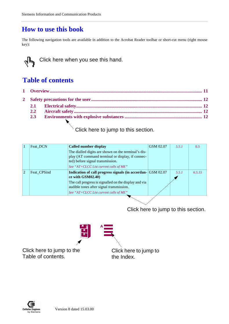
How to use this bookThe following navigation tools are available in addition to the Acrobat Reader toolbar or short-cut menu (right mousekey):
Click here when you see this hand.
Click here to jump to this section.
Table of contents
1 Overview.................................................................................................................................... 11
2 Safety precautions for the user................................................................................................ 122.1 Electrical safety............................................................................................................. 122.2 Aircraft safety ............................................................................................................... 122.3 Environments with explosive substances ................................................................... 12
Click here to jump to this section.
1 Feat_DCN Called number display The dialled digits are shown on the terminal’s dis-play (AT command terminal or display, if connec-ted) before signal transmission.
See “AT+CLCC List current calls of ME”
GSM 02.07 5.5.1 6.5
2 Feat_CPSind Indication of call progress signals (in accordan-ce with GSM02.40)The call progress is signalled on the display and via audible tones after signal transmission.
See “AT+CLCC List current calls of ME”
GSM 02.07 5.5.1 6.5.15
Click here to jump to the Table of contents.
Click here to jump to the Index.
A
Siemens Information and Communication Products
Table of contents
1 Overview 7
2 Safety precautions for the user 82.1 Electrical safety.................................................................................................................... 82.2 Aircraft safety ...................................................................................................................... 82.3 Environments with explosive substances .......................................................................... 82.4 Safety on the road................................................................................................................ 82.5 Non-ionizing radiation ........................................................................................................ 82.6 Electronics in medical equipment ...................................................................................... 82.7 Precautions in the event of loss/theft of the Cellular Engine and the SIM card............ 8
3 General product description M20 93.1 Teleservices ........................................................................................................................ 103.2 Data services ...................................................................................................................... 113.3 Mobile station features...................................................................................................... 113.4 Supplementary mobile station features........................................................................... 143.5 System requirements......................................................................................................... 153.6 CE conformity.................................................................................................................... 15
4 Hardware interfaces 164.1 Pin assignment of the 80-pole SMD connector ............................................................... 164.2 Power supply...................................................................................................................... 174.3 Interfaces on the 80-pole SMD connector ....................................................................... 174.4 Audio interface .................................................................................................................. 254.5 Antenna interface .............................................................................................................. 26
5 AT command interface 275.1 Syntax of the standard AT commands ............................................................................ 275.2 Messages returned for normal data communication ..................................................... 275.3 Standard AT Hayes commands for controlling the M20............................................... 285.4 AT commands and responses to GSM 07.07 and GSM 07.05 ....................................... 545.5 AT Cellular commands to GSM 07.07............................................................................. 555.6 AT commands to GSM 07.05 for SMS ............................................................................ 935.7 Siemens-defined AT commands for enhanced functions............................................. 1115.8 Comparison between the MMI string commands and AT command ........................ 1385.9 Summary of CME - CMS Errors................................................................................... 139
6 Man Machine Interface 1426.1 Overview........................................................................................................................... 1426.2 Keypad address matrix ................................................................................................... 1426.3 Additional display information ...................................................................................... 1436.4 MMI features and user-defined settings ....................................................................... 1436.5 MMI functions ................................................................................................................. 1466.6 Power supply indicator ................................................................................................... 153
7 Peripheral devices 1547.1 GSM antenna ................................................................................................................... 1547.2 SIM card reader .............................................................................................................. 1547.3 SIM cards ......................................................................................................................... 156
Version 8 dated 15.03.00 3A
Siemens Information and Communication Products
9. 219 220 220. 221
7.4 Handset............................................................................................................................. 1567.5 Sources for connectors .................................................................................................... 1577.6 Display .............................................................................................................................. 1577.7 Keypad.............................................................................................................................. 158
8 Application notes 1598.1 General notes ................................................................................................................... 1598.2 Getting started & Installation ........................................................................................ 1598.3 M20 diagnostics ............................................................................................................... 1748.4 Serial interface configuration......................................................................................... 1778.5 SW download (Version update) ..................................................................................... 1918.6 EMC-relevant information for integrators of the M20 ............................................... 1968.7 Getting full-type approval with the application ........................................................... 1968.8 Application examples and reference circuits ................................................................ 1988.9 Service information ........................................................................................................ 201
9 M20 Terminal 2029.1 General information........................................................................................................ 2029.2 Electrical description and interfaces ............................................................................. 2039.3 Operation requirements, CE conformity, restrictions of use...................................... 2069.4 Full-type approval ........................................................................................................... 206
10 M20 Development Box 207
11 Environmental requirements for the M20 207
12 EMC and ESD requirements 207
13 Migration M1 to M20 20713.1 SW comparison.............................................................................................................. 20713.2 System Parameter comparison (AT&V) on the M1 and M20................................... 209
14 References 211
15 Technical data 21215.1 Technical data of the M20 ............................................................................................ 21215.2 Design drawing of the M20........................................................................................... 21315.3 Design drawing of the M20 Terminal.......................................................................... 214
16 AT commands sorted by functionality 21716.1 Commands for Call Control......................................................................................... 21716.2 Commands for network services and status information.......................................... 21716.3 Commands for supplementary network services ....................................................... 21816.4 Commands for SIM....................................................................................................... 21816.5 Commands for interface to terminal equipment (TA – TE) ..................................... 2116.6 Commands for device control .....................................................................................16.7 Commands for device Information..............................................................................16.8 Commands for SMS and CB (GSM 07.05) .................................................................16.9 Commands for data/fax ...............................................................................................
17 Appendix 22117.1 Version History.............................................................................................................. 221
Version 8 dated 15.03.00 4A
Siemens Information and Communication Products
Figures
Fig. 3-1 Design of the Siemens M20 ........................................................................................ 9Fig. 3-2 M20 interface diagram .............................................................................................. 15Fig. 4-1 Timing of power on/off signals ................................................................................. 18Fig. 4-2 Write timing of display interface ............................................................................... 19Fig. 4-3 Read timing of display interface ............................................................................... 19Fig. 4-4 Timing characteristics of DAI to microcontroller ..................................................... 23Fig. 4-5 Timing characteristics of DAI to codec .................................................................... 23Fig. 6-1 Display structure ...................................................................................................... 143Fig. 7-1 Big SIM Card Reader (L04) .................................................................................... 154Fig. 7-2 Mini SIM card reader (C707-1) ............................................................................... 155Fig. 7-3 Mini SIM card reader (C707-3) ............................................................................... 155Fig. 7-4 Mini SIM card reader (holder) ................................................................................ 155Fig. 7-5 Mini SIM card reader (connector) ........................................................................... 155Fig. 7-6 SMR connector (straight) ........................................................................................ 157Fig. 7-7 80-pole SMD connector (rigid) ............................................................................... 157Fig. 7-8 80-pole SMD connector (floating) .......................................................................... 157Fig. 8-8 Handsfree application diagram ................................................................................ 200Fig. 8-4 Level converter ........................................................................................................ 198Fig. 8-5 Voltage supply ......................................................................................................... 198Fig. 8-6 SIM card connection pins ........................................................................................ 199Fig. 8-7 Handset connection ................................................................................................. 199Fig. 9-1 Modular Cellular Engine Siemens M20 Terminal .................................................. 202Fig. 9-2 Front view of Western plug 6-6 (male) ................................................................... 203Fig. 9-3 Front view of Western plug 4-4 (male) ................................................................... 204Fig. 15-1 Design drawing of the M20 ..................................................................................... 213Fig. 15-2 M20 screw dimensions ............................................................................................ 214Fig. 15-3 M20 Terminal front view ........................................................................................ 214Fig. 15-4 M20 Terminal back view ........................................................................................ 214Fig. 15-5 M20 Terminal top and side view ............................................................................. 215Fig. 15-6 M20 Terminal bottom view ..................................................................................... 216
Tables
Table 3-1 Teleservices ............................................................................................................... 10Table 3-2 Mobile station features .............................................................................................. 13Table 3-3 Supplementary mobile station features ..................................................................... 14Table 4-1 Pin assignment of the 80-pole SMD connector ......................................................... 16Table 4-2 2.8 V logic level specification ................................................................................... 17Table 4-3 Timing values of display interface ............................................................................ 20Table 4-4 Timing characteristics of DAI ................................................................................... 24Table 5-1 Standard Hayes AT commands ................................................................................. 29Table 5-2 AT commands according to GSM 07.07 ................................................................... 55Table 5-3 AT commands according to GSM 07.05 ................................................................... 94Table 5-4 Siemens-defined AT commands ............................................................................. 112Table 5-5 Summary of CMS ERRORS ................................................................................... 140Table 6-1 Keypad address matrix ............................................................................................ 142Table 6-2 Description of keypad ............................................................................................. 142
Version 8 dated 15.03.00 5A
Siemens Information and Communication Products
Table 6-3 M20-specific MMI codes ........................................................................................ 144Table 6-4 Languages for display text ...................................................................................... 144Table 6-5 Value ranges ............................................................................................................ 144Table 6-6 Basic MMI codes in accordance with ETS 300-511 ............................................... 145Table 6-7 Teleservices ts ......................................................................................................... 145Table 6-8 Changing the password in accordance with ETS 300-511 ...................................... 145Table 6-9 Service indicator display ......................................................................................... 152
Version 8 dated 15.03.00 6A

OverviewSiemens Information and Communication Products
5
se -
.
1 OverviewThis document describes all the features, functions and interfaces of the Siemens M20 and M20 Terminal Cellular Eng-ines. In addition, it states the base unit requirements which apply in connection with the operation of M20/M20 Terminal.
M20 Terminal combines the functions of the M20 unit with all peripheral devices necessary for plug-and-play usage (SIMcard reader, V.24 serial Interface, Western plugs for handset and power supply) and a wide range of supply voltages. Foradditional information on M20 Terminal, see Chapter 9 “M20 Terminal” on page 202.
This document also includes the list of AT commands implemented at the serial interface and describes the MMI imple-mented at the display and keypad interface, the options for external M20 diagnostics, safety precautions for M20 usersand M20 technical data.
In addition, this document provides service information and application notes and indicates the sources of componentsnecessary for operation e.g. SIM reader, handset, display and keypad.
Chapters on application notes with information on getting started, diagnostics and type approval complete this document.
IMPORTANT:
Users of the M20 are expressly requested to begin by reading the safety precautions in Chapter 2 “Safety precautions for theuser” on page 8.
Information on finding out the software status is provided in Chapter 5.5 “AT Cellular commands to GSM 07.07” on page 5(AT+GMR, AT+CGMR).
If you have any technical questions regarding this document or the product described, please contact your localdistributor.
General information on cellular engines and a list of distributors can be found at the following Internet addresses:
• English language: www.siemens.de/gsm_e• Deutsche Sprache: www.siemens.de/gsm
LIFE SUPPORT APPLICATIONSThese products are not designed for use in life support appliances, devices, or systems where malfunction of theproducts can reasonably expected to result in personal injury. SIEMENS AG customers using or selling these products for use in such applications do so at their risk and agree to fully idemnify SIEMENS AG for any damages resulting from such improper use or sale.
DEVELOPMENT BOX (E-BOX)Furthermore the Development box supplied by SIEMENS AG is to be used for development and test purposes onlyThe general terms of delivery or guarantee for the M20/M20T are not applicable for the Development box
This technical description applies to all M20 devices with SW Version 3.3 or higher and version number S30880-S8000-A100-1.
Version 8 dated 15.03.00 7A
Safety precautions for the userSiemens Information and Communication Products
rminalperma-against
ots, che-
tion, ex-e traffic.
rmal ope-
devices.
avoid
2 Safety precautions for the userThe following notes refer to the M20/M20 Terminal Cellular Engine AND to applications based on M20/M20 Terminal.The manufacturer of an application based on the M20/M20 Terminal must incorporate these safety precautions in his/herinstruction manual.
2.1 Electrical safetyThe highest internal voltage applied to the M20 is 6 V; no special precautions are thus required to protect users againsthigh voltages (see Chapter 4.2 “Power supply” on page 17).
2.2 Aircraft safetyCellular engines can interfere with an aircraft’s navigation system and its cellular network. The use of M20/M20 Teon board aircraft is forbidden by law. Failure to comply with this prohibition may lead to temporary suspension or nent cancellation of cellular engine services for the person who infringes this prohibition and/or to legal action said person.
2.3 Environments with explosive substancesa) Users are advised not to use the device in automotive service stations.
b) Users are reminded of the necessity to comply with restrictions regarding the use of radio devices in fuel depmicals plants and locations where explosives are ignited.
2.4 Safety on the roada) It is not permitted to signal incoming calls by sounding the vehicle’s horn or flashing the lights.
b) Drivers are advised not to use the hand-held microphone or the telephone handset while their vehicle is in mocept in the case of emergency. Use the handsfree facility to speak only if it does not divert your attention from th
2.5 Non-ionizing radiationAs is the case with other mobile radio transmitters, operating personnel are advised to use the device in the norating position only in order to ensure optimum performance and safety.
2.6 Electronics in medical equipmentRadio transmitters, including cellular engines, can interfere with the operation of inadequately protected medical Please address all questions to a doctor or the manufacturer of the medical device.
2.7 Precautions in the event of loss/theft of the Cellular Engine and the SIMcardIf your M20/M20 Terminal, your SIM card or both go missing, notify your network operator immediately in order to misuse.
Version 8 dated 15.03.00 8A
General product description M20Siemens Information and Communication Products
ile
nnected
ted circuit
only mi-
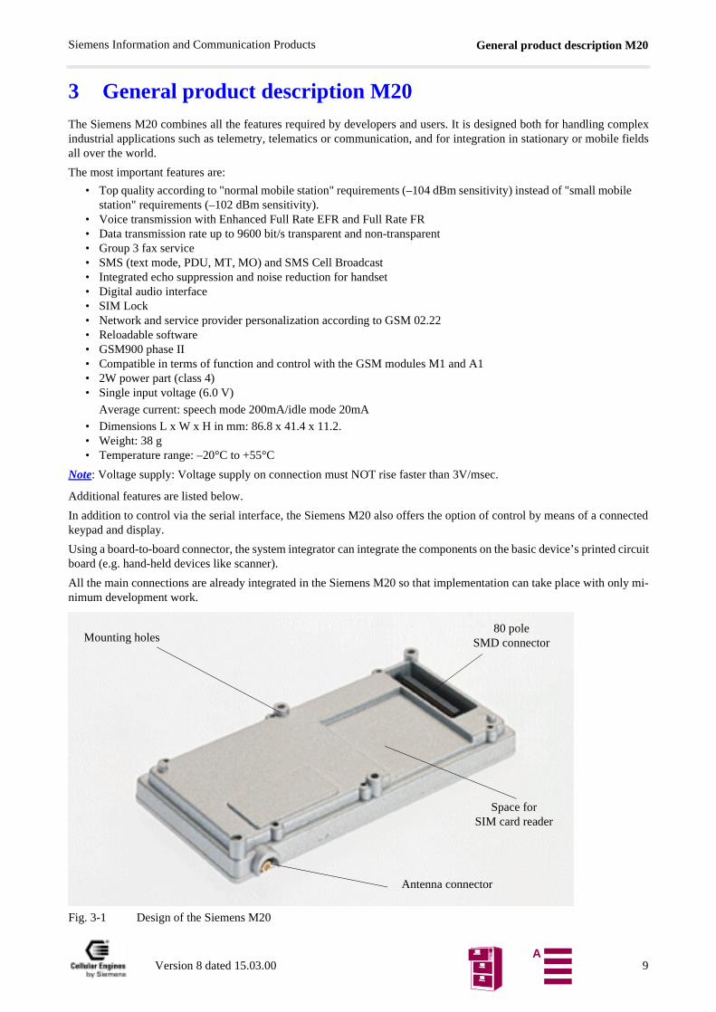
3 General product description M20The Siemens M20 combines all the features required by developers and users. It is designed both for handling complexindustrial applications such as telemetry, telematics or communication, and for integration in stationary or mobile fieldsall over the world.
The most important features are:
• Top quality according to "normal mobile station" requirements (–104 dBm sensitivity) instead of "small mobstation" requirements (–102 dBm sensitivity).
• Voice transmission with Enhanced Full Rate EFR and Full Rate FR• Data transmission rate up to 9600 bit/s transparent and non-transparent• Group 3 fax service• SMS (text mode, PDU, MT, MO) and SMS Cell Broadcast• Integrated echo suppression and noise reduction for handset• Digital audio interface• SIM Lock• Network and service provider personalization according to GSM 02.22• Reloadable software • GSM900 phase II• Compatible in terms of function and control with the GSM modules M1 and A1• 2W power part (class 4)• Single input voltage (6.0 V)
Average current: speech mode 200mA/idle mode 20mA
• Dimensions L x W x H in mm: 86.8 x 41.4 x 11.2.• Weight: 38 g• Temperature range: –20°C to +55°C
Note: Voltage supply: Voltage supply on connection must NOT rise faster than 3V/msec.
Additional features are listed below.
In addition to control via the serial interface, the Siemens M20 also offers the option of control by means of a cokeypad and display.
Using a board-to-board connector, the system integrator can integrate the components on the basic device’s prinboard (e.g. hand-held devices like scanner).
All the main connections are already integrated in the Siemens M20 so that implementation can take place with nimum development work.
Fig. 3-1 Design of the Siemens M20
Antenna connector
Space forSIM card reader
Mounting holes80 pole
SMD connector
Version 8 dated 15.03.00 9A
General product description M20Siemens Information and Communication Products
tion,
the world-
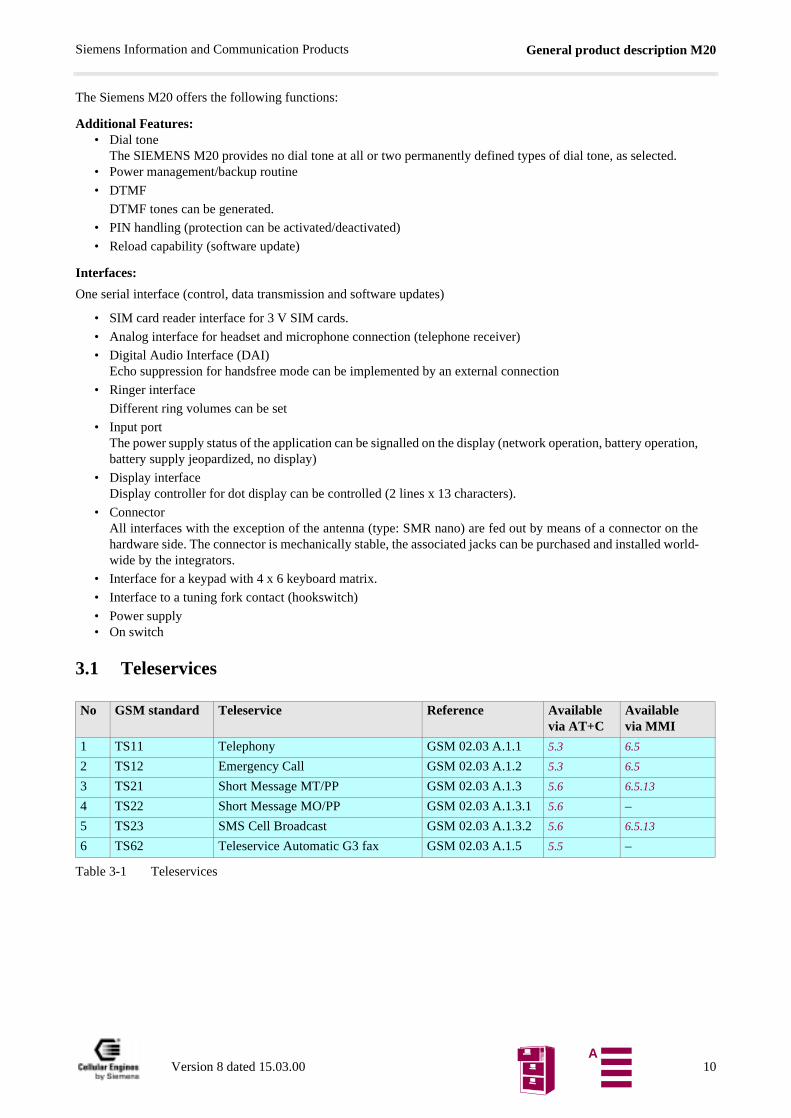
The Siemens M20 offers the following functions:
Additional Features:• Dial tone
The SIEMENS M20 provides no dial tone at all or two permanently defined types of dial tone, as selected.• Power management/backup routine
• DTMF
DTMF tones can be generated.
• PIN handling (protection can be activated/deactivated)
• Reload capability (software update)
Interfaces:
One serial interface (control, data transmission and software updates)
• SIM card reader interface for 3 V SIM cards.
• Analog interface for headset and microphone connection (telephone receiver)
• Digital Audio Interface (DAI)Echo suppression for handsfree mode can be implemented by an external connection
• Ringer interface
Different ring volumes can be set
• Input portThe power supply status of the application can be signalled on the display (network operation, battery operabattery supply jeopardized, no display)
• Display interfaceDisplay controller for dot display can be controlled (2 lines x 13 characters).
• ConnectorAll interfaces with the exception of the antenna (type: SMR nano) are fed out by means of a connector onhardware side. The connector is mechanically stable, the associated jacks can be purchased and installedwide by the integrators.
• Interface for a keypad with 4 x 6 keyboard matrix.
• Interface to a tuning fork contact (hookswitch)
• Power supply• On switch
3.1 Teleservices
Table 3-1 Teleservices
No GSM standard Teleservice Reference Availablevia AT+C
Available via MMI
1 TS11 Telephony GSM 02.03 A.1.1 5.3 6.5
2 TS12 Emergency Call GSM 02.03 A.1.2 5.3 6.5
3 TS21 Short Message MT/PP GSM 02.03 A.1.3 5.6 6.5.13
4 TS22 Short Message MO/PP GSM 02.03 A.1.3.1 5.6 –
5 TS23 SMS Cell Broadcast GSM 02.03 A.1.3.2 5.6 6.5.13
6 TS62 Teleservice Automatic G3 fax GSM 02.03 A.1.5 5.5 –
Version 8 dated 15.03.00 10A
General product description M20Siemens Information and Communication Products
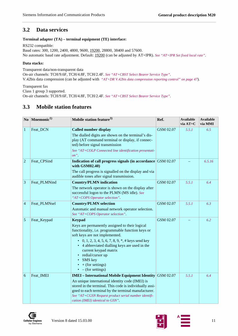
3.2 Data services
Terminal adapter (TA) – terminal equipment (TE) interface:
RS232 compatible:Baud rates: 300, 1200, 2400, 4800, 9600, 19200, 28800, 38400 and 57600.No automatic baud rate adjustment. Default: 19200 (can be adjusted by AT+IPR). See “AT+IPR Set fixed local rate”.
Data stacks:
Transparent data/non-transparent dataOn-air channels: TCH/9.6F, TCH/4.8F, TCH/2.4F. See “AT+CBST Select Bearer Service Type”.V.42bis data compression (can be adjusted with “AT+DR V.42bis data compression reporting control” on page 47).
Transparent faxClass 1 group 3 supported.On-air channels: TCH/9.6F, TCH/4.8F, TCH/2.4F. See “AT+CBST Select Bearer Service Type”.
3.3 Mobile station features
No Mnemonic1) Mobile station feature3) Ref. Available via AT+C
Available via MMI
1 Feat_DCN Called number displayThe dialled digits are shown on the terminal’s dis-play (AT command terminal or display, if connec-ted) before signal transmission
See “AT+COLP Connected line identification presentati-on” .
GSM 02.07 5.5.1 6.5
2 Feat_CPSind Indication of call progress signals (in accordancewith GSM02.40)The call progress is signalled on the display and via audible tones after signal transmission.
GSM 02.07 – 6.5.16
3 Feat_PLMNind Country/PLMN indicationThe network operator is shown on the display after successful logon to the PLMN (MS idle). See “AT+COPS Operator selection”.
GSM 02.07 5.5.1 6.4
4 Feat_PLMNsel Country/PLMN selectionAutomatic and manual network operator selection. See “AT+COPS Operator selection”.
GSM 02.07 5.5.1 6.3
5 Feat_Keypad KeypadKeys are permanently assigned to their logical functionality, i.e. programmable function keys or soft keys are not implemented.
• 0, 1, 2, 3, 4, 5, 6, 7, 8, 9, *, # keys send key• 4 abbreviated dialling keys are used in the
current keypad matrix• redial/cursor up• SMS key• + (for settings)• – (for settings)
GSM 02.07 – 6.2
6 Feat_IMEI IMEI – International Mobile Equipment IdentityAn unique international identity code (IMEI) is stored in the terminal. This code is individually assi-gned to each terminal by the terminal manufacturer. See “AT+CGSN Request product serial number identifi-cation (IMEI) identical to GSN”.
GSM 02.07 5.5.1 6.4
Version 8 dated 15.03.00 11A
General product description M20Siemens Information and Communication Products
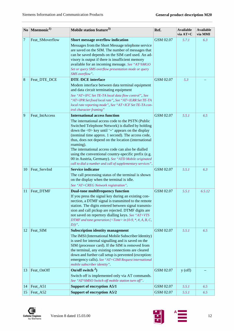
7 Feat_SMoverflow Short message overflow indicationMessages from the Short Message telephone service are saved on the SIM. The number of messages that can be saved depends on the SIM card used. An ad-visory is output if there is insufficient memory available for an incoming message. See “AT^SMGO Set or query SMS overflow presentation mode or query SMS overflow”.
GSM 02.07 5.7.1 6.3
8 Feat_DTE_DCE DTE /DCE interface Modem interface between data terminal equipment and data circuit terminating equipment
See “AT+IFC Set TE-TA local data flow control”, See “AT+IPR Set fixed local rate”, See “AT+ILRR Set TE-TA local rate reporting mode”, See “AT+ICF Set TE-TA con-trol character framing”
GSM 02.07 5.3 –
9 Feat_IntAccess International access functionThe international access code to the PSTN (Public Switched Telephone Network) is dialled by holding down the <0> key until ‘+’ appears on the display (nominal time approx. 1 second). The access code, thus, does not depend on the location (international roaming). The international access code can also be dialled using the conventional country-specific prefix (e.g. 00 in Austria, Germany). See “ATD Mobile originated call to dial a number and call of supplementary services”.
GSM 02.07 5.5.1 6.5
10 Feat_ServInd Service indicator The call processing status of the terminal is shown on the display when the terminal is idle.
See “AT+CREG Network registration”.
GSM 02.07 5.5.1 6.3
11 Feat_DTMF Dual-tone multifrequency functionIf you press the signal key during an existing con-nection, a DTMF signal is transmitted to the remote station. The digits entered between signal transmis-sion and call pickup are rejected. DTMF digits are not saved on repertory dialling keys. See “AT+VTS DTMF and tone generation (<Tone> in 0-9, *, #, A, B, C, D)” .
GSM 02.07 5.5.1 6.5.12
12 Feat_SIM Subscription identity managementThe IMSI (International Mobile Subscriber Identity) is used for internal signalling and is saved on the SIM (processor card). If the SIM is removed from the terminal, any existing connections are cleared down and further call setup is prevented (exception: emergency calls). See “AT+CIMI Request international mobile subscriber identity”.
GSM 02.07 5.5.1 6.5
13 Feat_OnOff On/off switch 2)Switch off is implemented only via AT commands. See “AT^SMSO Switch off mobile station turn off”.
GSM 02.07 y (off) –
14 Feat_A51 Support of encryption A5/1 GSM 02.07 5.5.1 6.5
15 Feat_A52 Support of encryption A5/2 GSM 02.07 5.5.1 6.5
No Mnemonic1) Mobile station feature3) Ref. Available via AT+C
Available via MMI
Version 8 dated 15.03.00 12A
General product description M20Siemens Information and Communication Products
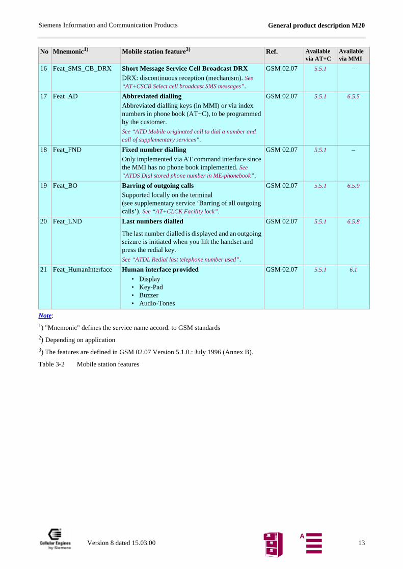
Note:
1) "Mnemonic" defines the service name accord. to GSM standards
2) Depending on application
3) The features are defined in GSM 02.07 Version 5.1.0.: July 1996 (Annex B).
Table 3-2 Mobile station features
16 Feat_SMS_CB_DRX Short Message Service Cell Broadcast DRXDRX: discontinuous reception (mechanism). See “AT+CSCB Select cell broadcast SMS messages”.
GSM 02.07 5.5.1 –
17 Feat_AD Abbreviated dialling Abbreviated dialling keys (in MMI) or via index numbers in phone book (AT+C), to be programmed by the customer.
See “ATD Mobile originated call to dial a number and call of supplementary services”.
GSM 02.07 5.5.1 6.5.5
18 Feat_FND Fixed number dialling Only implemented via AT command interface since the MMI has no phone book implemented. See “ATDS Dial stored phone number in ME-phonebook”.
GSM 02.07 5.5.1 –
19 Feat_BO Barring of outgoing calls Supported locally on the terminal (see supplementary service ‘Barring of all outgoing calls’). See “AT+CLCK Facility lock”.
GSM 02.07 5.5.1 6.5.9
20 Feat_LND Last numbers dialled
The last number dialled is displayed and an outgoing seizure is initiated when you lift the handset and press the redial key.
See “ATDL Redial last telephone number used”.
GSM 02.07 5.5.1 6.5.8
21 Feat_HumanInterface Human interface provided
• Display• Key-Pad• Buzzer• Audio-Tones
GSM 02.07 5.5.1 6.1
No Mnemonic1) Mobile station feature3) Ref. Available via AT+C
Available via MMI
Version 8 dated 15.03.00 13A
General product description M20Siemens Information and Communication Products
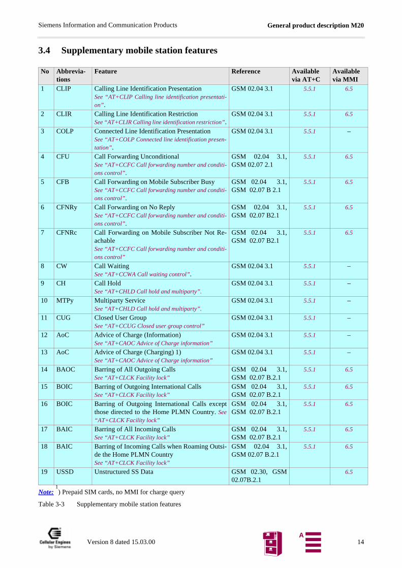
3.4 Supplementary mobile station features
Note: 1) Prepaid SIM cards, no MMI for charge query
Table 3-3 Supplementary mobile station features
No Abbrevia-tions
Feature Reference Availablevia AT+C
Availablevia MMI
1 CLIP Calling Line Identification PresentationSee “AT+CLIP Calling line identification presentati-on” .
GSM 02.04 3.1 5.5.1 6.5
2 CLIR Calling Line Identification RestrictionSee “AT+CLIR Calling line identification restriction”.
GSM 02.04 3.1 5.5.1 6.5
3 COLP Connected Line Identification PresentationSee “AT+COLP Connected line identification presen-tation” .
GSM 02.04 3.1 5.5.1 –
4 CFU Call Forwarding UnconditionalSee “AT+CCFC Call forwarding number and conditi-ons control”.
GSM 02.04 3.1,GSM 02.07 2.1
5.5.1 6.5
5 CFB Call Forwarding on Mobile Subscriber BusySee “AT+CCFC Call forwarding number and conditi-ons control”.
GSM 02.04 3.1,GSM 02.07 B 2.1
5.5.1 6.5
6 CFNRy Call Forwarding on No ReplySee “AT+CCFC Call forwarding number and conditi-ons control”.
GSM 02.04 3.1,GSM 02.07 B2.1
5.5.1 6.5
7 CFNRc Call Forwarding on Mobile Subscriber Not Re-achableSee “AT+CCFC Call forwarding number and conditi-ons control”
GSM 02.04 3.1,GSM 02.07 B2.1
5.5.1 6.5
8 CW Call WaitingSee “AT+CCWA Call waiting control”.
GSM 02.04 3.1 5.5.1 –
9 CH Call HoldSee “AT+CHLD Call hold and multiparty”.
GSM 02.04 3.1 5.5.1 –
10 MTPy Multiparty ServiceSee “AT+CHLD Call hold and multiparty”.
GSM 02.04 3.1 5.5.1 –
11 CUG Closed User GroupSee “AT+CCUG Closed user group control”
GSM 02.04 3.1 5.5.1 –
12 AoC Advice of Charge (Information)See “AT+CAOC Advice of Charge information”
GSM 02.04 3.1 5.5.1 –
13 AoC Advice of Charge (Charging) 1)See “AT+CAOC Advice of Charge information”
GSM 02.04 3.1 5.5.1 –
14 BAOC Barring of All Outgoing CallsSee “AT+CLCK Facility lock”
GSM 02.04 3.1,GSM 02.07 B.2.1
5.5.1 6.5
15 BOIC Barring of Outgoing International CallsSee “AT+CLCK Facility lock”
GSM 02.04 3.1,GSM 02.07 B.2.1
5.5.1 6.5
16 BOIC Barring of Outgoing International Calls exceptthose directed to the Home PLMN Country. See“AT+CLCK Facility lock”
GSM 02.04 3.1,GSM 02.07 B.2.1
5.5.1 6.5
17 BAIC Barring of All Incoming CallsSee “AT+CLCK Facility lock”
GSM 02.04 3.1,GSM 02.07 B.2.1
5.5.1 6.5
18 BAIC Barring of Incoming Calls when Roaming Outsi-de the Home PLMN CountrySee “AT+CLCK Facility lock”
GSM 02.04 3.1,GSM 02.07 B.2.1
5.5.1 6.5
19 USSD Unstructured SS Data GSM 02.30, GSM02.07B.2.1
6.5
Version 8 dated 15.03.00 14A
General product description M20Siemens Information and Communication Products
3.5 System requirementsThe M20 is designed for use in a system environment comprising a GSM900 mobile radio network with one or more net-work operators per country. A corresponding infrastructure for a configuration level suitable for the use of terminal de-vices with 2 watts transmitting power is a basic requirement.
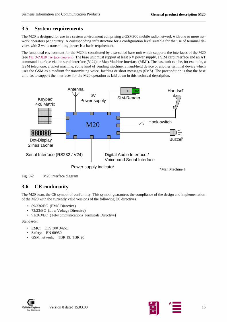
The functional environment for the M20 is constituted by a so-called base unit which supports the interfaces of the M20(see Fig. 3-2 M20 interface diagram). The base unit must support at least 6 V power supply, a SIM card interface and an ATcommand interface via the serial interface (V.24) or Man Machine Interface (MMI). The base unit can be, for example, aGSM telephone, a ticket machine, some kind of vending machine, a hand-held device or another terminal device whichuses the GSM as a medium for transmitting voice, fax/data or short messages (SMS). The precondition is that the baseunit has to support the interfaces for the M20 operation as laid down in this technical description.
Fig. 3-2 M20 interface diagram
3.6 CE conformityThe M20 bears the CE symbol of conformity. This symbol guarantees the compliance of the design and implementationof the M20 with the currently valid versions of the following EC directives.
• 89/336/EC (EMC Directive)• 73/23/EC (Low Voltage Directive)• 91/263/EC (Telecommunications Terminals Directive)
Standards:
• EMC: ETS 300 342-1• Safety: EN 60950• GSM network: TBR 19, TBR 20
Serial Interface (RS232 / V24)
M20
SIM-Reader
Buzzer
Hook-switch
Dot-Display2lines 16char
Keypad4x6 Matrix
Antenna Handset6V
Power supply
SIM
Digital Audio Interface /Voiceband Serial Interface
Power supply indicator
*
*
*
*
**Man Machine In
Version 8 dated 15.03.00 15A
Hardware interfacesSiemens Information and Communication Products
4 Hardware interfaces
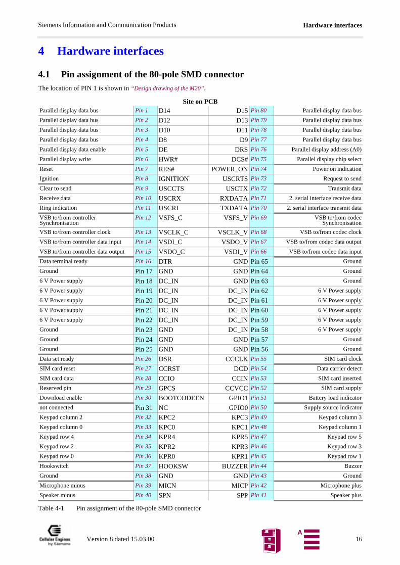
4.1 Pin assignment of the 80-pole SMD connectorThe location of PIN 1 is shown in “Design drawing of the M20”.
Site on PCB
Table 4-1 Pin assignment of the 80-pole SMD connector
Parallel display data bus Pin 1 D14 D15 Pin 80 Parallel display data bus
Parallel display data bus Pin 2 D12 D13 Pin 79 Parallel display data bus
Parallel display data bus Pin 3 D10 D11 Pin 78 Parallel display data bus
Parallel display data bus Pin 4 D8 D9 Pin 77 Parallel display data bus
Parallel display data enable Pin 5 DE DRS Pin 76 Parallel display address (A0)
Parallel display write Pin 6 HWR# DCS# Pin 75 Parallel display chip select
Reset Pin 7 RES# POWER_ON Pin 74 Power on indication
Ignition Pin 8 IGNITION USCRTS Pin 73 Request to send
Clear to send Pin 9 USCCTS USCTX Pin 72 Transmit data
Receive data Pin 10 USCRX RXDATA Pin 71 2. serial interface receive data
Ring indication Pin 11 USCRI TXDATA Pin 70 2. serial interface transmit data
VSB to/from controller Synchronisation
Pin 12 VSFS_C VSFS_V Pin 69 VSB to/from codecSynchronisation
VSB to/from controller clock Pin 13 VSCLK_C VSCLK_V Pin 68 VSB to/from codec clock
VSB to/from controller data input Pin 14 VSDI_C VSDO_V Pin 67 VSB to/from codec data output
VSB to/from controller data output Pin 15 VSDO_C VSDI_V Pin 66 VSB to/from codec data input
Data terminal ready Pin 16 DTR GND Pin 65 Ground
Ground Pin 17 GND GND Pin 64 Ground
6 V Power supply Pin 18 DC_IN GND Pin 63 Ground
6 V Power supply Pin 19 DC_IN DC_IN Pin 62 6 V Power supply
6 V Power supply Pin 20 DC_IN DC_IN Pin 61 6 V Power supply
6 V Power supply Pin 21 DC_IN DC_IN Pin 60 6 V Power supply
6 V Power supply Pin 22 DC_IN DC_IN Pin 59 6 V Power supply
Ground Pin 23 GND DC_IN Pin 58 6 V Power supply
Ground Pin 24 GND GND Pin 57 Ground
Ground Pin 25 GND GND Pin 56 Ground
Data set ready Pin 26 DSR CCCLK Pin 55 SIM card clock
SIM card reset Pin 27 CCRST DCD Pin 54 Data carrier detect
SIM card data Pin 28 CCIO CCIN Pin 53 SIM card inserted
Reserved pin Pin 29 GPCS CCVCC Pin 52 SIM card supply
Download enable Pin 30 BOOTCODEEN GPIO1 Pin 51 Battery load indicator
not connected Pin 31 NC GPIO0 Pin 50 Supply source indicator
Keypad column 2 Pin 32 KPC2 KPC3 Pin 49 Keypad column 3
Keypad column 0 Pin 33 KPC0 KPC1 Pin 48 Keypad column 1
Keypad row 4 Pin 34 KPR4 KPR5 Pin 47 Keypad row 5
Keypad row 2 Pin 35 KPR2 KPR3 Pin 46 Keypad row 3
Keypad row 0 Pin 36 KPR0 KPR1 Pin 45 Keypad row 1
Hookswitch Pin 37 HOOKSW BUZZER Pin 44 Buzzer
Ground Pin 38 GND GND Pin 43 Ground
Microphone minus Pin 39 MICN MICP Pin 42 Microphone plus
Speaker minus Pin 40 SPN SPP Pin 41 Speaker plus
Version 8 dated 15.03.00 16A
Hardware interfacesSiemens Information and Communication Products
ctede (10
WN,
The interfaces are described in detail in Chapters 4.2 “Power supply” on page 17, 4.3 “Interfaces on the 80-pole SMD connector”on page 17 and 4.4 “Audio interface” on page 25.
Note: Unused pins
• In all cases in which the DAI is not used, the voiceband serial connector to/from controller has to be conneexternally to the voiceband serial connector to/from codec. Connection wires should be as short as possiblcm maximum) Connect VSFS_V to VSFS_C, VSCLK_V to VSCLK_C, VSDO_V to VSDI_C, VSDI_V to VSDO_C. For ad-ditional information, see also Chapter 8.8.5 “Adding echo suppression functionality” on page 200.
• RXDATA must be connected to RES#, if not used.• The following pins (if unused) shall be:
connected to GND: CCINconnected to a 10 kOhm - 100 kOhm pull-down (ground) resistor: BOOTCODEEN, GPIO0, GPIO1, HOOKSnot connected: all display pins, all keypad pins, USCxxx, MICN, MICP, BUZZER, SPN, SPP, POWER_ORES#, DSR, DCD, TXDATA, DTR, GPCS.
• All DC_IN pins and all GND pins shall be used!
• The maximum number of push-pull cycles of the SMD connector shall not exceed 100.
4.2 Power supplySingle voltage power supply: 6V +/- 0.2 V
Current consumption: max. 2A pulses.
Switch-in current pulse Imax = 15 A, duration: approx. 10 µs,
(when voltage is applied) decreasing (1/e) time constant <90 µs at Rsupply<0.1Ωdecreasing time to stand-by current value: < 300 µs
Stand-by state I ≤ 0.2 mA
(voltage is applied, ignition not yet asserted)
Idle mode I < 20 mA averagetyp. 14 mA average (depends on network operator)
Call in progress I < 2A (pulsed t = 577 µs at T = 4.615 ms)typ. 1.5 A for performance class 5arithmetic mean: I < 250 mA
4.3 Interfaces on the 80-pole SMD connectorThis chapter describes all interfaces (except power supply) on the 80-pole SMD connector.
4.3.1 Specification of 2.8 V logic level
The following diagram shows the 2.8 V logic level specification used in the M20:
Table 4-2 2.8 V logic level specification
Parameter Min. Max.
VoH output high voltage 2.3 V 2.9 V
VoL output low voltage 0 V 0.4 V
ViH input high voltage 2.1 V 3 V
ViL input low voltage -0.3 V 0.8 V
Version 8 dated 15.03.00 17A
Hardware interfacesSiemens Information and Communication Products
unning corre-
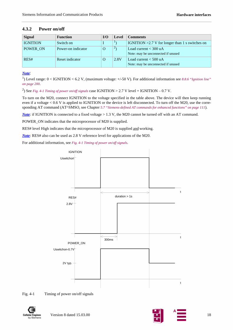
4.3.2 Power on/off
Note:1) Level range: 0 < IGNITION < 6.2 V, (maximum voltage: +/-50 V). For additional information see 8.8.6 “Ignition line”on page 200.
2) See Fig. 4-1 Timing of power on/off signals case IGNITION > 2.7 V level = IGNITION – 0.7 V.
To turn on the M20, connect IGNITION to the voltage specified in the table above. The device will then keep reven if a voltage < 0.6 V is applied to IGNITION or the device is left disconnected. To turn off the M20, use thesponding AT command (AT^SMSO, see Chapter 5.7 “Siemens-defined AT commands for enhanced functions” on page 111).
Note: if IGNITION is connected to a fixed voltage > 1.3 V, the M20 cannot be turned off with an AT command.
POWER_ON indicates that the microprocessor of M20 is supplied.
RES# level High indicates that the microprocessor of M20 is supplied and working.
Note: RES# also can be used as 2.8 V reference level for applications of the M20.
For additional information, see Fig. 4-1 Timing of power on/off signals.
Fig. 4-1 Timing of power on/off signals
Signal Function I/O Level Comments
IGNITION Switch on I 1) IGNITION >2.7 V for longer than 1 s switches on
POWER_ON Power-on indicator O 2) Load current < 300 uANote: may be unconnected if unused
RES# Reset indicator O 2.8V Load current < 500 uANote: may be unconnected if unused
Uswitchon
IGNITION
t
2.8V
RES#
t
Uswitchon-0.7V
POWER_ON
t
2V typ.
300ms
duration > 1s
Version 8 dated 15.03.00 18A
Hardware interfacesSiemens Information and Communication Products
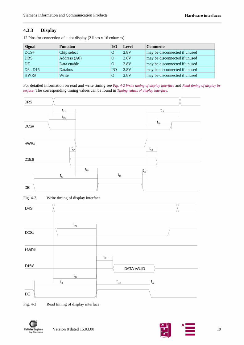
4.3.3 Display
12 Pins for connection of a dot display (2 lines x 16 columns)
For detailed information on read and write timing see Fig. 4-2 Write timing of display interface and Read timing of display in-terface. The corresponding timing values can be found in Timing values of display interface.
Fig. 4-2 Write timing of display interface
Fig. 4-3 Read timing of display interface
Signal Function I/O Level CommentsDCS# Chip select O 2.8V may be disconnected if unused
DRS Address (A0) O 2.8V may be disconnected if unused
DE Data enable O 2.8V may be disconnected if unused
D8...D15 Databus I/O 2.8V may be disconnected if unused
HWR# Write O 2.8V may be disconnected if unused
DCS#
HWR#
DRS
DE
t10
t11
t13 t14
t15
t16
D15:8
t12
t17 t18
t19
DCS#
HWR#
DRS
DE
t20
t11a
D15:8
t12t23
t21
t22
DATA VALID
Version 8 dated 15.03.00 19A
Hardware interfacesSiemens Information and Communication Products
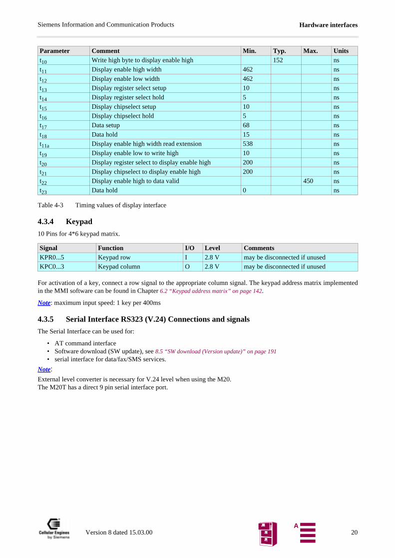
Table 4-3 Timing values of display interface
4.3.4 Keypad
10 Pins for 4*6 keypad matrix.
For activation of a key, connect a row signal to the appropriate column signal. The keypad address matrix implementedin the MMI software can be found in Chapter 6.2 “Keypad address matrix” on page 142.
Note: maximum input speed: 1 key per 400ms
4.3.5 Serial Interface RS323 (V.24) Connections and signals
The Serial Interface can be used for:
• AT command interface• Software download (SW update), see 8.5 “SW download (Version update)” on page 191• serial interface for data/fax/SMS services.
Note: External level converter is necessary for V.24 level when using the M20.The M20T has a direct 9 pin serial interface port.
Parameter Comment Min. Typ. Max. Unitst10 Write high byte to display enable high 152 ns
t11 Display enable high width 462 ns
t12 Display enable low width 462 ns
t13 Display register select setup 10 ns
t14 Display register select hold 5 ns
t15 Display chipselect setup 10 ns
t16 Display chipselect hold 5 ns
t17 Data setup 68 ns
t18 Data hold 15 ns
t11a Display enable high width read extension 538 ns
t19 Display enable low to write high 10 ns
t20 Display register select to display enable high 200 ns
t21 Display chipselect to display enable high 200 ns
t22 Display enable high to data valid 450 ns
t23 Data hold 0 ns
Signal Function I/O Level CommentsKPR0...5 Keypad row I 2.8 V may be disconnected if unused
KPC0...3 Keypad column O 2.8 V may be disconnected if unused
Version 8 dated 15.03.00 20A
Hardware interfacesSiemens Information and Communication Products
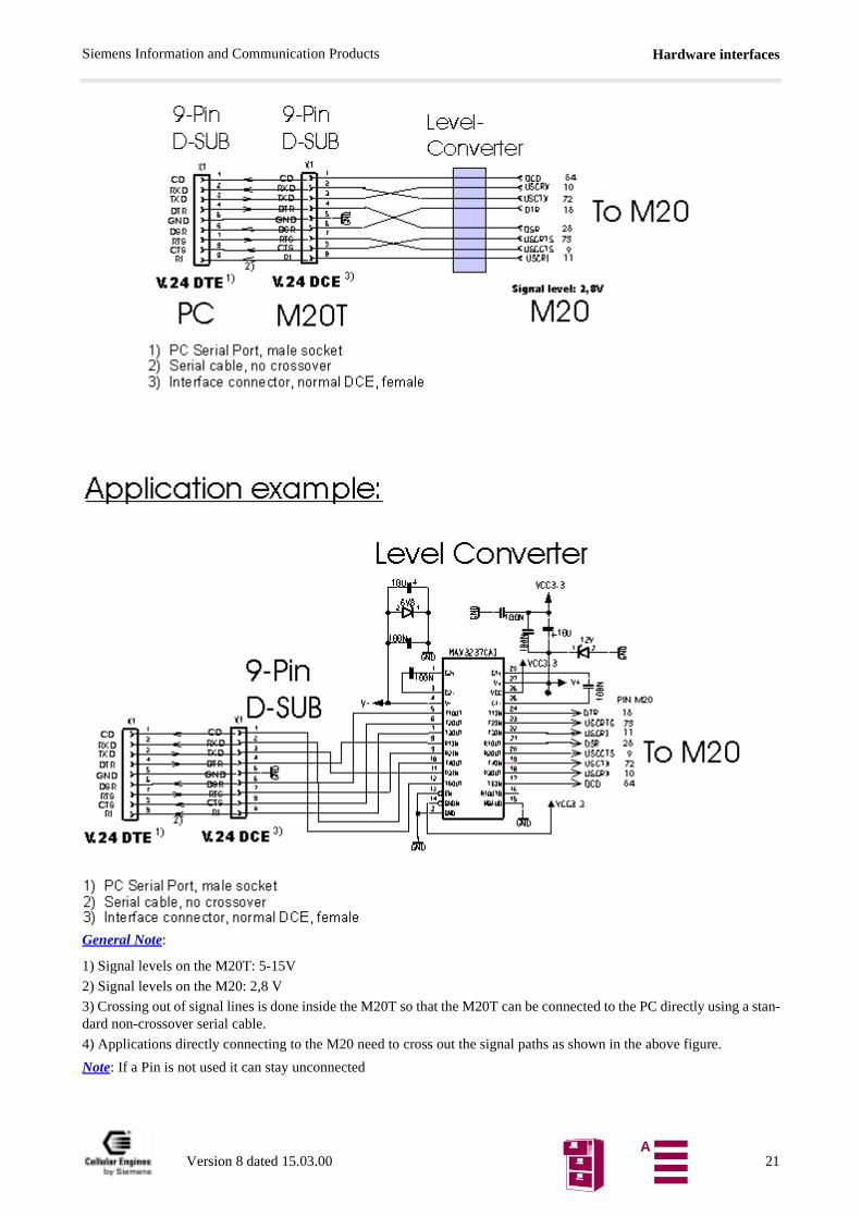
General Note:
1) Signal levels on the M20T: 5-15V
2) Signal levels on the M20: 2,8 V
3) Crossing out of signal lines is done inside the M20T so that the M20T can be connected to the PC directly using a stan-dard non-crossover serial cable.
4) Applications directly connecting to the M20 need to cross out the signal paths as shown in the above figure.
Note: If a Pin is not used it can stay unconnected
Version 8 dated 15.03.00 21A
Hardware interfacesSiemens Information and Communication Products
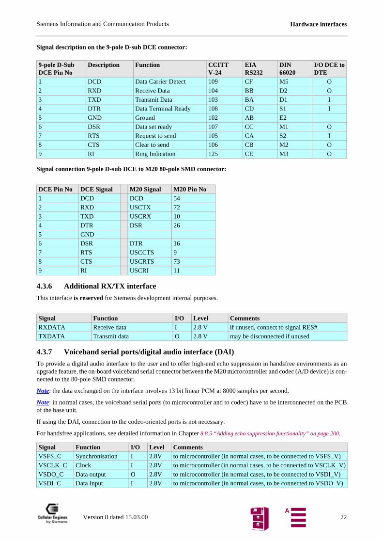
Signal description on the 9-pole D-sub DCE connector:
Signal connection 9-pole D-sub DCE to M20 80-pole SMD connector:
4.3.6 Additional RX/TX interface
This interface is reserved for Siemens development internal purposes.
4.3.7 Voiceband serial ports/digital audio interface (DAI)
To provide a digital audio interface to the user and to offer high-end echo suppression in handsfree environments as anupgrade feature, the on-board voiceband serial connector between the M20 microcontroller and codec (A/D device) is con-nected to the 80-pole SMD connector.
Note: the data exchanged on the interface involves 13 bit linear PCM at 8000 samples per second.
Note: in normal cases, the voiceband serial ports (to microcontroller and to codec) have to be interconnected on the PCBof the base unit.
If using the DAI, connection to the codec-oriented ports is not necessary.
For handsfree applications, see detailed information in Chapter 8.8.5 “Adding echo suppression functionality” on page 200.
9-pole D-Sub DCE Pin No
Description Function CCITTV-24
EIARS232
DIN66020
I/O DCE toDTE
1 DCD Data Carrier Detect 109 CF M5 O
2 RXD Receive Data 104 BB D2 O
3 TXD Transmit Data 103 BA D1 I
4 DTR Data Terminal Ready 108 CD S1 I
5 GND Ground 102 AB E2
6 DSR Data set ready 107 CC M1 O
7 RTS Request to send 105 CA S2 I
8 CTS Clear to send 106 CB M2 O
9 RI Ring Indication 125 CE M3 O
DCE Pin No DCE Signal M20 Signal M20 Pin No1 DCD DCD 54
2 RXD USCTX 72
3 TXD USCRX 10
4 DTR DSR 26
5 GND
6 DSR DTR 16
7 RTS USCCTS 9
8 CTS USCRTS 73
9 RI USCRI 11
Signal Function I/O Level CommentsRXDATA Receive data I 2.8 V if unused, connect to signal RES#
TXDATA Transmit data O 2.8 V may be disconnected if unused
Signal Function I/O Level CommentsVSFS_C Synchronisation I 2.8V to microcontroller (in normal cases, to be connected to VSFS_V)
VSCLK_C Clock I 2.8V to microcontroller (in normal cases, to be connected to VSCLK_V)
VSDO_C Data output O 2.8V to microcontroller (in normal cases, to be connected to VSDI_V)
VSDI_C Data Input I 2.8V to microcontroller (in normal cases, to be connected to VSDO_V)
Version 8 dated 15.03.00 22A
Hardware interfacesSiemens Information and Communication Products
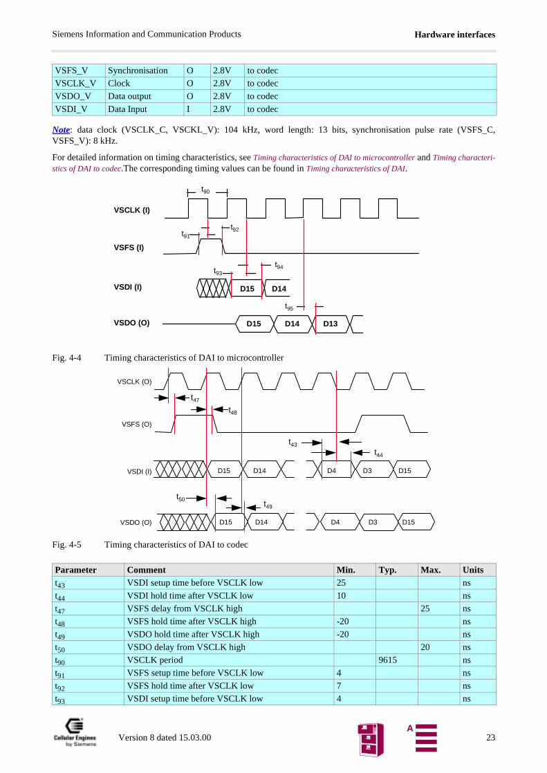
Note: data clock (VSCLK_C, VSCKL_V): 104 kHz, word length: 13 bits, synchronisation pulse rate (VSFS_C,VSFS_V): 8 kHz.
For detailed information on timing characteristics, see Timing characteristics of DAI to microcontroller and Timing characteri-stics of DAI to codec.The corresponding timing values can be found in Timing characteristics of DAI.
Fig. 4-4 Timing characteristics of DAI to microcontroller
Fig. 4-5 Timing characteristics of DAI to codec
VSFS_V Synchronisation O 2.8V to codec
VSCLK_V Clock O 2.8V to codec
VSDO_V Data output O 2.8V to codec
VSDI_V Data Input I 2.8V to codec
Parameter Comment Min. Typ. Max. Unitst43 VSDI setup time before VSCLK low 25 ns
t44 VSDI hold time after VSCLK low 10 ns
t47 VSFS delay from VSCLK high 25 ns
t48 VSFS hold time after VSCLK high -20 ns
t49 VSDO hold time after VSCLK high -20 ns
t50 VSDO delay from VSCLK high 20 ns
t90 VSCLK period 9615 ns
t91 VSFS setup time before VSCLK low 4 ns
t92 VSFS hold time after VSCLK low 7 ns
t93 VSDI setup time before VSCLK low 4 ns
VSCLK (I)
VSDI (I)
VSDO (O)
t90
D15 D14
VSFS (I)
t91
t92
t93
t94
t95
D15 D14 D13
VSDI (I)
VSDO (O)
VSCLK (O)
VSFS (O)
t43
t44
t47
t48
t50
D15 D14 D4 D3 D15
t49
D15 D14 D4 D3 D15
Version 8 dated 15.03.00 23A
Hardware interfacesSiemens Information and Communication Products
Table 4-4 Timing characteristics of DAI
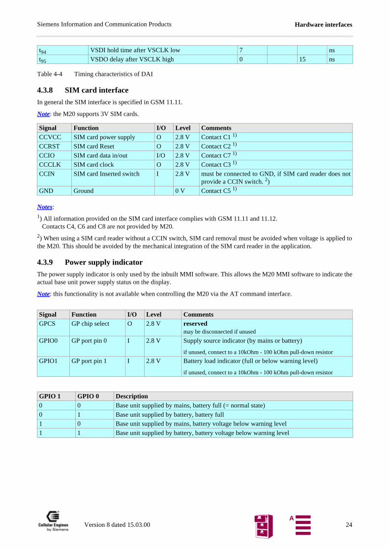
4.3.8 SIM card interface
In general the SIM interface is specified in GSM 11.11.
Note: the M20 supports 3V SIM cards.
Notes:
1) All information provided on the SIM card interface complies with GSM 11.11 and 11.12. Contacts C4, C6 and C8 are not provided by M20.
2) When using a SIM card reader without a CCIN switch, SIM card removal must be avoided when voltage is applied tothe M20. This should be avoided by the mechanical integration of the SIM card reader in the application.
4.3.9 Power supply indicator
The power supply indicator is only used by the inbuilt MMI software. This allows the M20 MMI software to indicate theactual base unit power supply status on the display.
Note: this functionality is not available when controlling the M20 via the AT command interface.
t94 VSDI hold time after VSCLK low 7 ns
t95 VSDO delay after VSCLK high 0 15 ns
Signal Function I/O Level CommentsCCVCC SIM card power supply O 2.8 V Contact C1 1)
CCRST SIM card Reset O 2.8 V Contact C2 1)
CCIO SIM card data in/out I/O 2.8 V Contact C7 1)
CCCLK SIM card clock O 2.8 V Contact C3 1)
CCIN SIM card Inserted switch I 2.8 V must be connected to GND, if SIM card reader does notprovide a CCIN switch. 2)
GND Ground 0 V Contact C5 1)
Signal Function I/O Level CommentsGPCS GP chip select O 2.8 V reserved
may be disconnected if unused
GPIO0 GP port pin 0 I 2.8 V Supply source indicator (by mains or battery)
if unused, connect to a 10kOhm - 100 kOhm pull-down resistor
GPIO1 GP port pin 1 I 2.8 V Battery load indicator (full or below warning level)
if unused, connect to a 10kOhm - 100 kOhm pull-down resistor
GPIO 1 GPIO 0 Description0 0 Base unit supplied by mains, battery full (= normal state)
0 1 Base unit supplied by battery, battery full
1 0 Base unit supplied by mains, battery voltage below warning level
1 1 Base unit supplied by battery, battery voltage below warning level
Version 8 dated 15.03.00 24A

Hardware interfacesSiemens Information and Communication Products
-
4.4 Audio interface
Note:1) Fscale = 10^((3*inBbcGain)/20) (for parameter "inBbcGain", see description of command AT^SNFI in Chapter 5.7 “Sie-mens-defined AT commands for enhanced functions” on page 111)
The microphone should comply with the following technical data:
Technical data of the speaker:
Signal Function I/O
Level Comments
MICP Microphone plus I Vpp(V): 1)typ.: 1.0954 / Fscalemax.: 1.578 / Fscale
Differential input; must be AC-coupled; input resistance: 11–22 MΩ Note: may be disconnected if unused
MICN Microphone minus I Vpp(V): 1)typ.: 1.0954 / Fscalemax.: 1.578 / Fscale
Differential Input; internally; must be AC-coupled; input resistance: 11–22 MΩ Note: may be disconnected if unused
SPP Speaker plus O Vpp(V):nom.: 2.1909max.: 3.156
min. load resistance: 32 Ωmax. load capacitance: 100 pFshould be AC-coupled
Note: may be disconnected if unused
SPN Speaker minus O Vpp(V):nom.: 2.1909max.: 3.156
min. load resistance: 32 Ωmax. load capacitance: 100 pFshould be AC-coupled
Note: may be unconnected if unused
BUZZER Buzzer O 1.2 V - 1.35 V > 2 kOhm, < 50 pF, used only with integrated MMI
Note: may be disconnected if unused
HOOKSW Hookswitch I 2.8 V used only with integrated MMI
ON-HOOK = 0VOFF-HOOK = 2.1 - 3 V
if unused, connect to a 10 kOhm - 100 kOhm pull-down resi-stor
Sensitivity -37 ± 2 dB (500 Hz, 0 dB = 1 V/Pa, v = 0)
Impedance 2 kΩ ± 30% (1 kHz)
Bias voltage 1.5 V DC (1–10 V DC)
Input current ≤ 300 µA
Signal-to-noise ratio ≤ 66 dB
Volume (97.0 ± 2) dB SPL
Impedance 150 ± 30 ΩTHD ≤ 4% (800 Hz, 104 dB SPL)
≤ 2% (300–3400 Hz, 94 dB SPL)
Version 8 dated 15.03.00 25A
Hardware interfacesSiemens Information and Communication Products
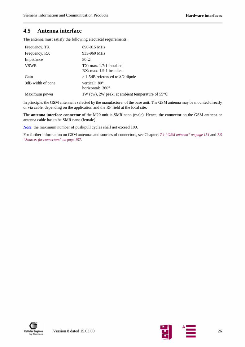
4.5 Antenna interfaceThe antenna must satisfy the following electrical requirements:
In principle, the GSM antenna is selected by the manufacturer of the base unit. The GSM antenna may be mounted directlyor via cable, depending on the application and the RF field at the local site.
The antenna interface connector of the M20 unit is SMR nano (male). Hence, the connector on the GSM antenna orantenna cable has to be SMR nano (female).
Note: the maximum number of push/pull cycles shall not exceed 100.
For further information on GSM antennas and sources of connectors, see Chapters 7.1 “GSM antenna” on page 154 and 7.5“Sources for connectors” on page 157.
Frequency, TX 890-915 MHz
Frequency, RX 935-960 MHz
Impedance 50 ΩVSWR TX: max. 1.7:1 installed
RX: max. 1.9:1 installed
Gain > 1.5dB referenced to λ/2 dipole
3dB width of cone vertical: 80°horizontal: 360°
Maximum power 1W (cw), 2W peak; at ambient temperature of 55°C
Version 8 dated 15.03.00 26A
AT command interfaceSiemens Information and Communication Products
plicable,
The com-
ch sub-ceived as the next
t/
m
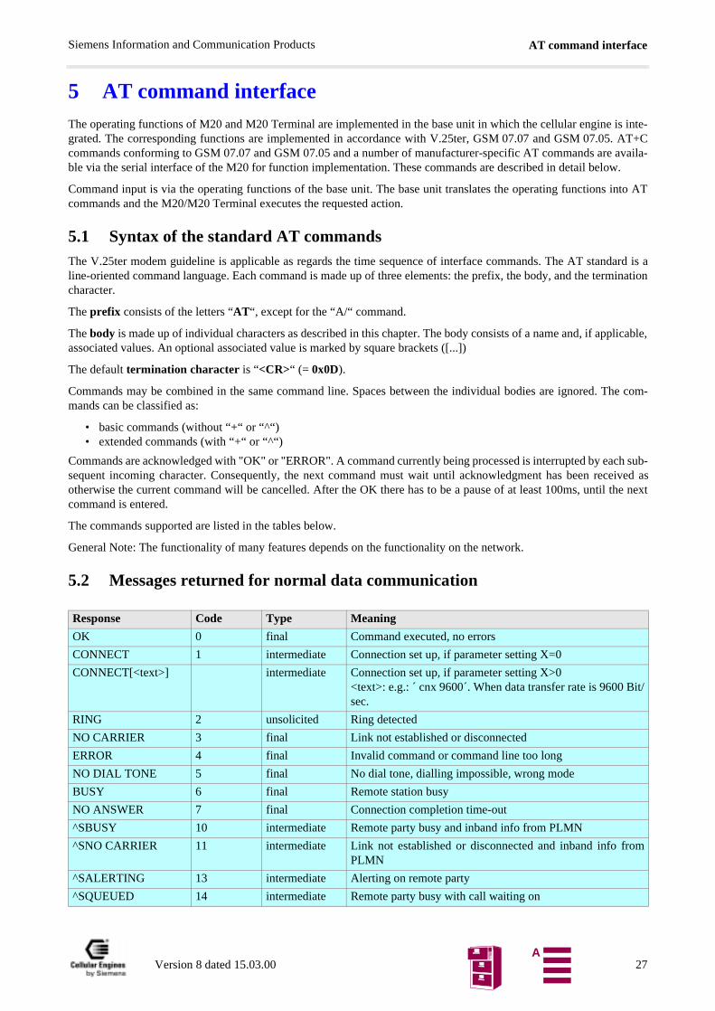
5 AT command interfaceThe operating functions of M20 and M20 Terminal are implemented in the base unit in which the cellular engine is inte-grated. The corresponding functions are implemented in accordance with V.25ter, GSM 07.07 and GSM 07.05. AT+Ccommands conforming to GSM 07.07 and GSM 07.05 and a number of manufacturer-specific AT commands are availa-ble via the serial interface of the M20 for function implementation. These commands are described in detail below.
Command input is via the operating functions of the base unit. The base unit translates the operating functions into ATcommands and the M20/M20 Terminal executes the requested action.
5.1 Syntax of the standard AT commandsThe V.25ter modem guideline is applicable as regards the time sequence of interface commands. The AT standard is aline-oriented command language. Each command is made up of three elements: the prefix, the body, and the terminationcharacter.
The prefix consists of the letters “AT“, except for the “A/“ command.
The body is made up of individual characters as described in this chapter. The body consists of a name and, if apassociated values. An optional associated value is marked by square brackets ([...])
The default termination character is “<CR>“ (= 0x0D).
Commands may be combined in the same command line. Spaces between the individual bodies are ignored. mands can be classified as:
• basic commands (without “+“ or “^“)• extended commands (with “+“ or “^“)
Commands are acknowledged with "OK" or "ERROR". A command currently being processed is interrupted by easequent incoming character. Consequently, the next command must wait until acknowledgment has been reotherwise the current command will be cancelled. After the OK there has to be a pause of at least 100ms, untilcommand is entered.
The commands supported are listed in the tables below.
General Note: The functionality of many features depends on the functionality on the network.
5.2 Messages returned for normal data communication
Response Code Type Meaning
OK 0 final Command executed, no errors
CONNECT 1 intermediate Connection set up, if parameter setting X=0
CONNECT[<text>] intermediate Connection set up, if parameter setting X>0<text>: e.g.: cnx 9600´. When data transfer rate is 9600 Bisec.
RING 2 unsolicited Ring detected
NO CARRIER 3 final Link not established or disconnected
ERROR 4 final Invalid command or command line too long
NO DIAL TONE 5 final No dial tone, dialling impossible, wrong mode
BUSY 6 final Remote station busy
NO ANSWER 7 final Connection completion time-out
^SBUSY 10 intermediate Remote party busy and inband info from PLMN
^SNO CARRIER 11 intermediate Link not established or disconnected and inband info froPLMN
^SALERTING 13 intermediate Alerting on remote party
^SQUEUED 14 intermediate Remote party busy with call waiting on
Version 8 dated 15.03.00 27A
AT command interfaceSiemens Information and Communication Products
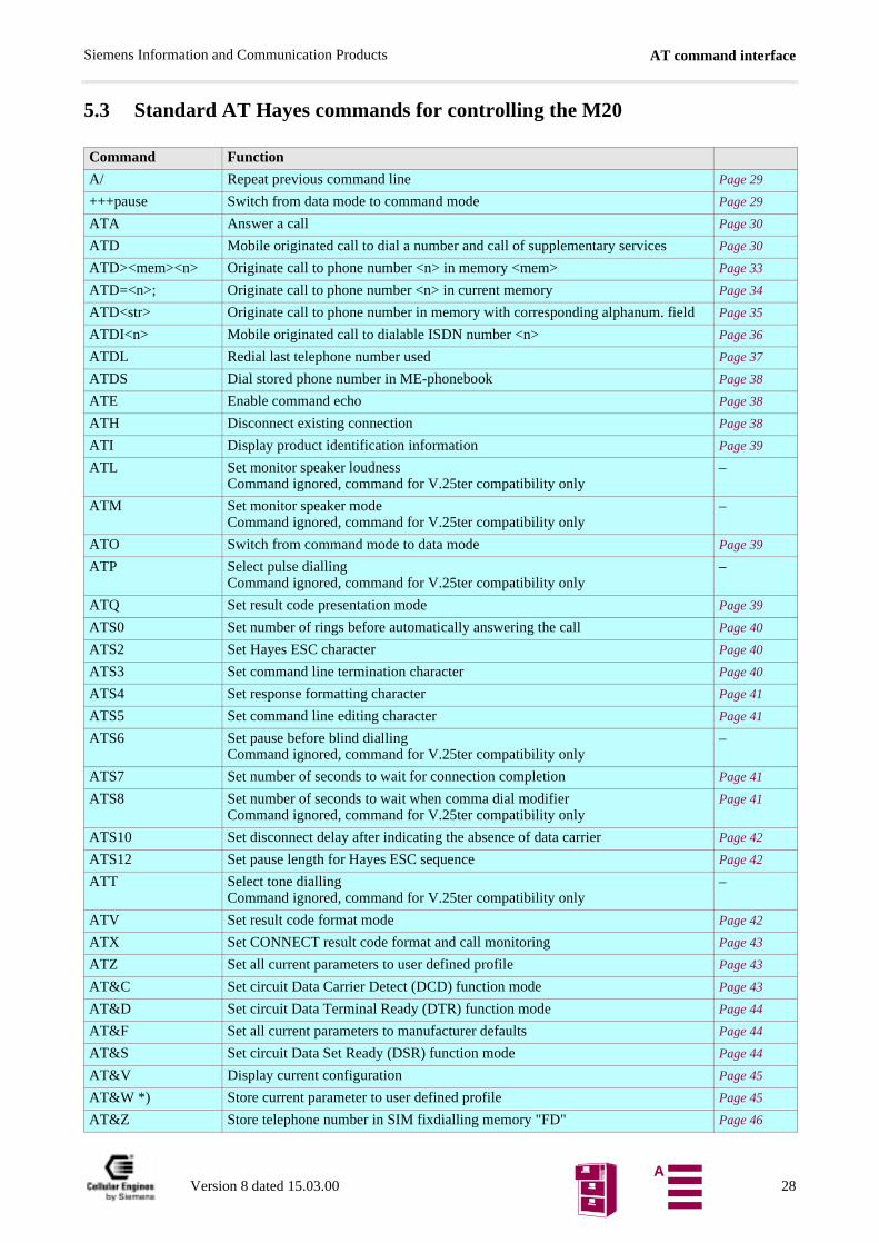
5.3 Standard AT Hayes commands for controlling the M20
Command Function
A/ Repeat previous command line Page 29
+++pause Switch from data mode to command mode Page 29
ATA Answer a call Page 30
ATD Mobile originated call to dial a number and call of supplementary services Page 30
ATD><mem><n> Originate call to phone number <n> in memory <mem> Page 33
ATD=<n>; Originate call to phone number <n> in current memory Page 34
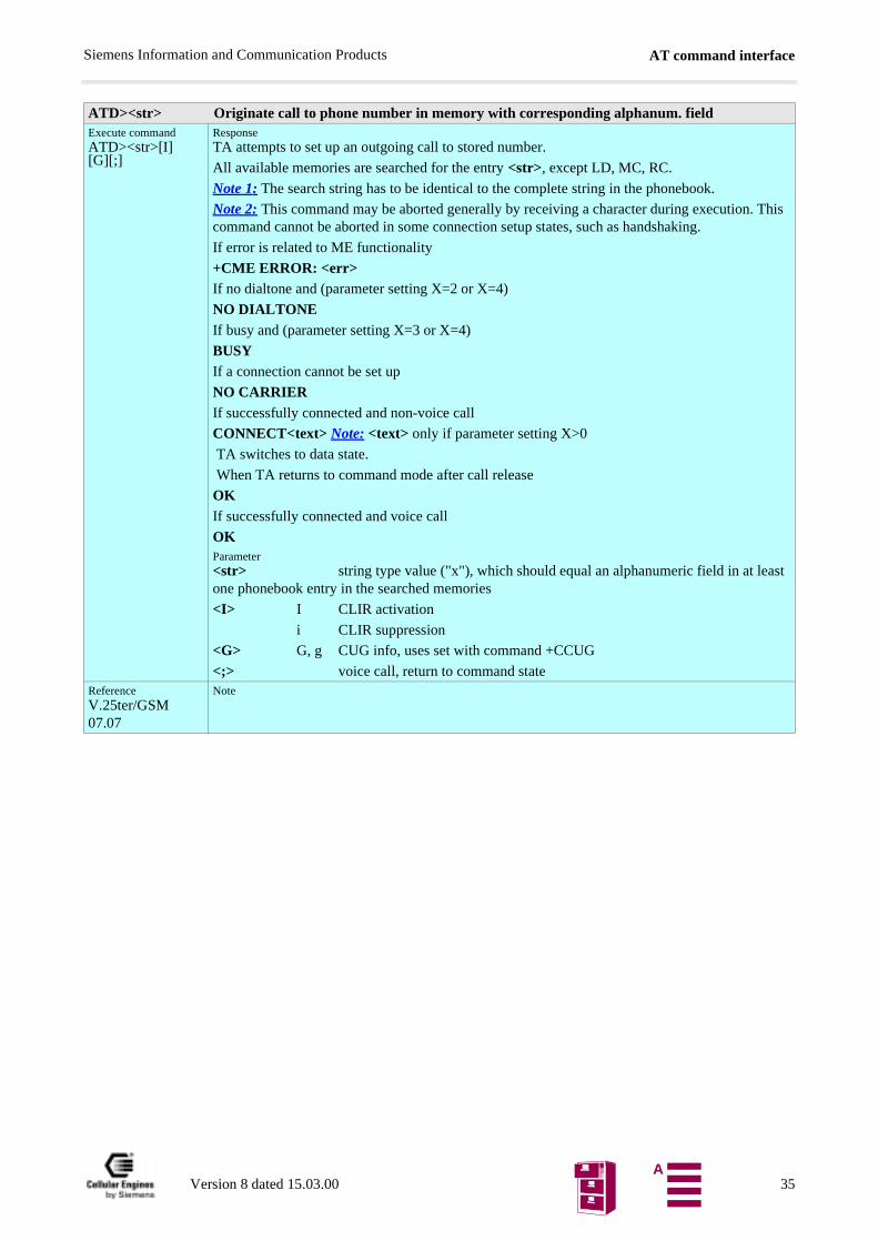
ATD<str> Originate call to phone number in memory with corresponding alphanum. field Page 35
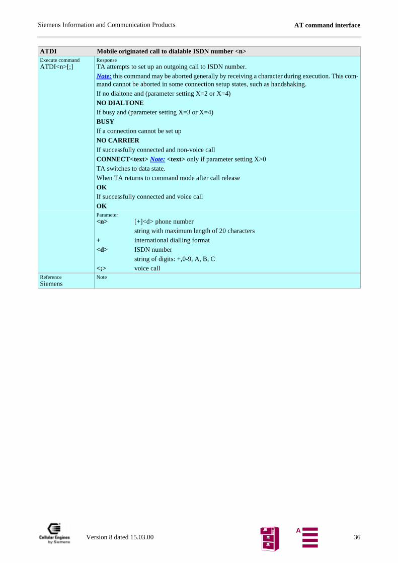
ATDI<n> Mobile originated call to dialable ISDN number <n> Page 36
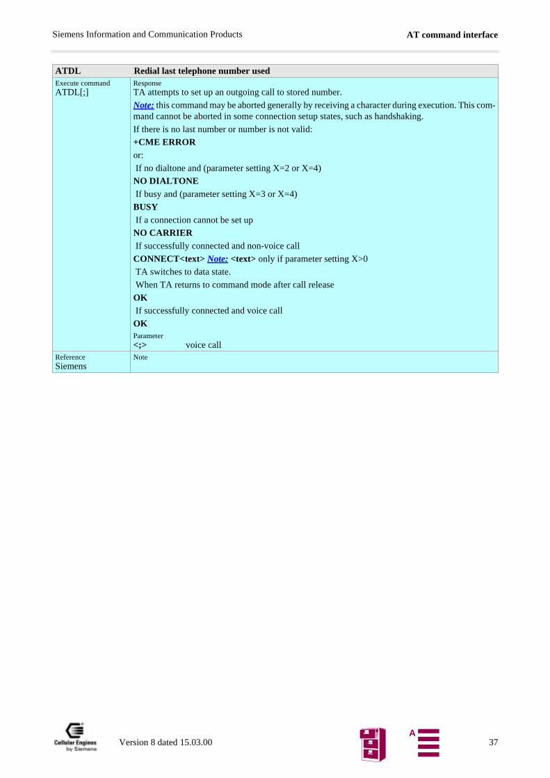
ATDL Redial last telephone number used Page 37
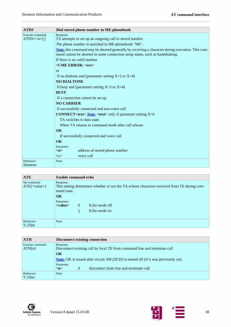
ATDS Dial stored phone number in ME-phonebook Page 38
ATE Enable command echo Page 38
ATH Disconnect existing connection Page 38
ATI Display product identification information Page 39
ATL Set monitor speaker loudnessCommand ignored, command for V.25ter compatibility only
–
ATM Set monitor speaker modeCommand ignored, command for V.25ter compatibility only
–
ATO Switch from command mode to data mode Page 39
ATP Select pulse diallingCommand ignored, command for V.25ter compatibility only
–
ATQ Set result code presentation mode Page 39
ATS0 Set number of rings before automatically answering the call Page 40
ATS2 Set Hayes ESC character Page 40
ATS3 Set command line termination character Page 40
ATS4 Set response formatting character Page 41
ATS5 Set command line editing character Page 41
ATS6 Set pause before blind diallingCommand ignored, command for V.25ter compatibility only
–
ATS7 Set number of seconds to wait for connection completion Page 41
ATS8 Set number of seconds to wait when comma dial modifierCommand ignored, command for V.25ter compatibility only
Page 41
ATS10 Set disconnect delay after indicating the absence of data carrier Page 42
ATS12 Set pause length for Hayes ESC sequence Page 42
ATT Select tone diallingCommand ignored, command for V.25ter compatibility only
–
ATV Set result code format mode Page 42
ATX Set CONNECT result code format and call monitoring Page 43
ATZ Set all current parameters to user defined profile Page 43
AT&C Set circuit Data Carrier Detect (DCD) function mode Page 43
AT&D Set circuit Data Terminal Ready (DTR) function mode Page 44
AT&F Set all current parameters to manufacturer defaults Page 44
AT&S Set circuit Data Set Ready (DSR) function mode Page 44
AT&V Display current configuration Page 45
AT&W *) Store current parameter to user defined profile Page 45
AT&Z Store telephone number in SIM fixdialling memory "FD" Page 46
Version 8 dated 15.03.00 28A
AT command interfaceSiemens Information and Communication Products
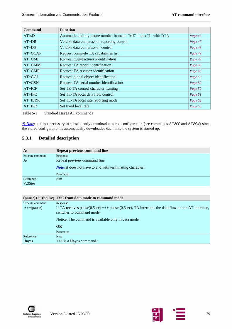
Table 5-1 Standard Hayes AT commands
*) Note: it is not necessary to subsequently download a stored configuration (see commands AT&Y and AT&W) sincethe stored configuration is automatically downloaded each time the system is started up.
5.3.1 Detailed description
AT%D Automatic dialling phone number in mem. "ME" index "1" with DTR Page 46
AT+DR V.42bis data compression reporting control Page 47
AT+DS V.42bis data compression control Page 48
AT+GCAP Request complete TA capabilities list Page 48
AT+GMI Request manufacturer identification Page 49
AT+GMM Request TA model identification Page 49
AT+GMR Request TA revision identification Page 49
AT+GOI Request global object identification Page 50
AT+GSN Request TA serial number identification Page 50
AT+ICF Set TE-TA control character framing Page 50
AT+IFC Set TE-TA local data flow control Page 51
AT+ILRR Set TE-TA local rate reporting mode Page 52
AT+IPR Set fixed local rate Page 53
A/ Repeat previous command lineExecute command
A/Response
Repeat previous command line
Note: it does not have to end with terminating character.
Parameter
Reference
V.25terNote
(pause)+++(pause) ESC from data mode to command modeExecute command
+++(pause)Response
If TA receives pause(0,5sec) +++ pause (0,5sec), TA interrupts the data flow on the AT interface,switches to command mode.
Notice: The command is available only in data mode.
OKParameter
Reference
HayesNote
+++ is a Hayes command.
Command Function
Version 8 dated 15.03.00 29A
AT command interfaceSiemens Information and Communication Products
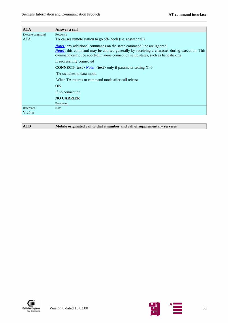
ATA Answer a callExecute command
ATAResponse
TA causes remote station to go off- hook (i.e. answer call).
Note1: any additional commands on the same command line are ignored.Note2: this command may be aborted generally by receiving a character during execution. Thiscommand cannot be aborted in some connection setup states, such as handshaking.
If successfully connected
CONNECT<text> Note: <text> only if parameter setting X>0
TA switches to data mode.
When TA returns to command mode after call release
OK
If no connection
NO CARRIERParameter
Reference
V.25terNote
ATD Mobile originated call to dial a number and call of supplementary services
Version 8 dated 15.03.00 30A
AT command interfaceSiemens Information and Communication Products
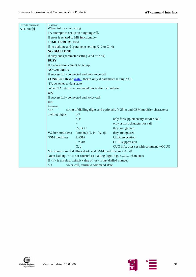
Execute command
ATD<n>[;]ResponseWhen <n> is a call string
TA attempts to set up an outgoing call.
If error is related to ME functionality
+CME ERROR: <err>If no dialtone and (parameter setting X=2 or X=4)
NO DIALTONE If busy and (parameter setting X=3 or X=4)
BUSYIf a connection cannot be set up
NO CARRIERIf successfully connected and non-voice call
CONNECT<text> Note: <text> only if parameter setting X>0
TA switches to data state.
When TA returns to command mode after call release
OKIf successfully connected and voice call
OKParameter<n> string of dialling digits and optionally V.25ter and GSM modifier characters:
dialling digits: 0-9
*, # only for supplementary service call
+ only as first character for call
A, B, C they are ignored
V.25ter modifiers: (comma), T, P,!, W, @ they are ignored
GSM modifiers: I, #31# CLIR invocation
i, *31# CLIR suppression
G, g CUG info, uses set with command +CCUG
Maximum sum of dialling digits and GSM modifiers in <n>: 20
Note: leading "+" is not counted as dialling digit. E.g. +...20... characters
If <n> is missing: default value of <n> is last dialled number
<;> voice call, return to command state
Version 8 dated 15.03.00 31A
AT command interfaceSiemens Information and Communication Products
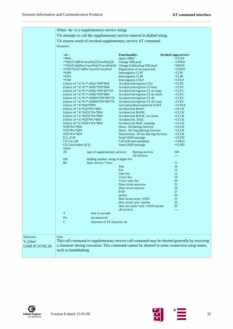
When <n> is a supplementary service string:
TA attempts to call the supplementary service entered in dialled string.
TA returns result of invoked supplementary service AT command.Parameter
Reference
V.25ter/GSM 07.07/02.30
NoteThis call command or supplementary service call command may be aborted generally by receiving a character during execution. This command cannot be aborted in some connection setup states, such as handshaking.
<n>: Functionality: Invoked supp.service:*#06# Query IMEI: +CGSN**04[2]*oldPin*newPin[2]*newPin[2]# Change SIM pwd: +CPWD**05[2]*unblKey*newPin[2]*newPin[2]# Change/Unblocking SIM pwd: ^SPWD*[*]03*[ZZ]*oldPw*newPw*newPw# Registration of net password: +CPWD*#30# Interrogation CLIP +CLIP*#31# Interrogation CLIR +CLIR*#76# Interrogation COLP +COLP(choice of *,#,*#,**,##)21*DN*BS# Act/deact/int/reg/eras CFU +CCFC(choice of *,#,*#,**,##)67*DN*BS# Act/deact/int/reg/eras CF busy +CCFC(choice of *,#,*#,**,##)61*DN*BS*T# Act/deact/int/reg/eras CF no reply +CCFC(choice of *,#,*#,**,##)62*DN*BS# Act/deact/int/reg/eras CF no reach +CCFC(choice of *,#,*#,**,##)002*DN*BS*T# Act/deact/int/reg/eras CF all +CCFC(choice of *,#,*#,**,##)004*DN*BS*T# Act/deact/int/reg/eras CF all cond. +CCFC(choice of *,#,*#)43*BS# Activation/deactivation/int WAIT +CCWA(choice of *,#,*#)33*Pw*BS# Act/deact/int BAOC +CLCK(choice of *,#,*#)331*Pw*BS# Act/deact/int BAOIC +CLCK(choice of *,#,*#)332*Pw*BS# Act/deact/int BAOIC exc.home +CLCK(choice of *,#,*#)35*Pw*BS# Act/deact/int. BAIC +CLCK(choice of *,#,*#)351*Pw*BS# Act/deact/int BAIC roaming +CLCK#330*Pw*BS# Deact. All Barring Services +CLCK#333*Pw*BS# Deact. All Outg.Barring Services +CLCK#353*Pw*BS# Deactivation. All Inc.Barring Services +CLCK[C]...[C]# Send USSD message +CUSDC[C] in call Call hold and multiparty +CHLDC[C] (excluded 1[C]) Send USSD message +CUSDwhereZZ type of supplementary services: Barring services 330
All services ----DN dialling number: string of digits 0-9BS basic service: Voice 11
Sms 16Fax 13Sms+fax 12Voice+fax 19Voice+sms+fax 10Data circuit asyncron 25Data circuit syncron 24PAD 27packet 26data circuit async.+PAD 21data circuit sync.+packet 22data circ.async+sync.+PAD+packet 20all services ----
T time in secondsPw net passwordC character of TE character set
Version 8 dated 15.03.00 32A
AT command interfaceSiemens Information and Communication Products
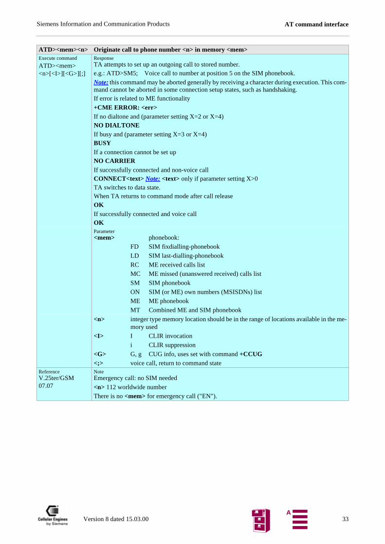
ATD><mem><n> Originate call to phone number <n> in memory <mem>Execute command
ATD><mem><n>[<I>][<G>][;]
ResponseTA attempts to set up an outgoing call to stored number.e.g.: ATD>SM5; Voice call to number at position 5 on the SIM phonebook.
Note: this command may be aborted generally by receiving a character during execution. This com-mand cannot be aborted in some connection setup states, such as handshaking.If error is related to ME functionality
+CME ERROR: <err>If no dialtone and (parameter setting X=2 or X=4)NO DIALTONE If busy and (parameter setting X=3 or X=4)BUSYIf a connection cannot be set upNO CARRIERIf successfully connected and non-voice callCONNECT<text> Note: <text> only if parameter setting X>0TA switches to data state.When TA returns to command mode after call releaseOKIf successfully connected and voice callOKParameter<mem> phonebook:
FD SIM fixdialling-phonebook
LD SIM last-dialling-phonebook
RC ME received calls list
MC ME missed (unanswered received) calls list
SM SIM phonebook
ON SIM (or ME) own numbers (MSISDNs) list
ME ME phonebook
MT Combined ME and SIM phonebook
<n> integer type memory location should be in the range of locations available in the me-mory used
<I> I CLIR invocation
i CLIR suppression
<G> G, g CUG info, uses set with command +CCUG<;> voice call, return to command state
ReferenceV.25ter/GSM 07.07
NoteEmergency call: no SIM needed
<n> 112 worldwide number
There is no <mem> for emergency call ("EN").
Version 8 dated 15.03.00 33A
AT command interfaceSiemens Information and Communication Products
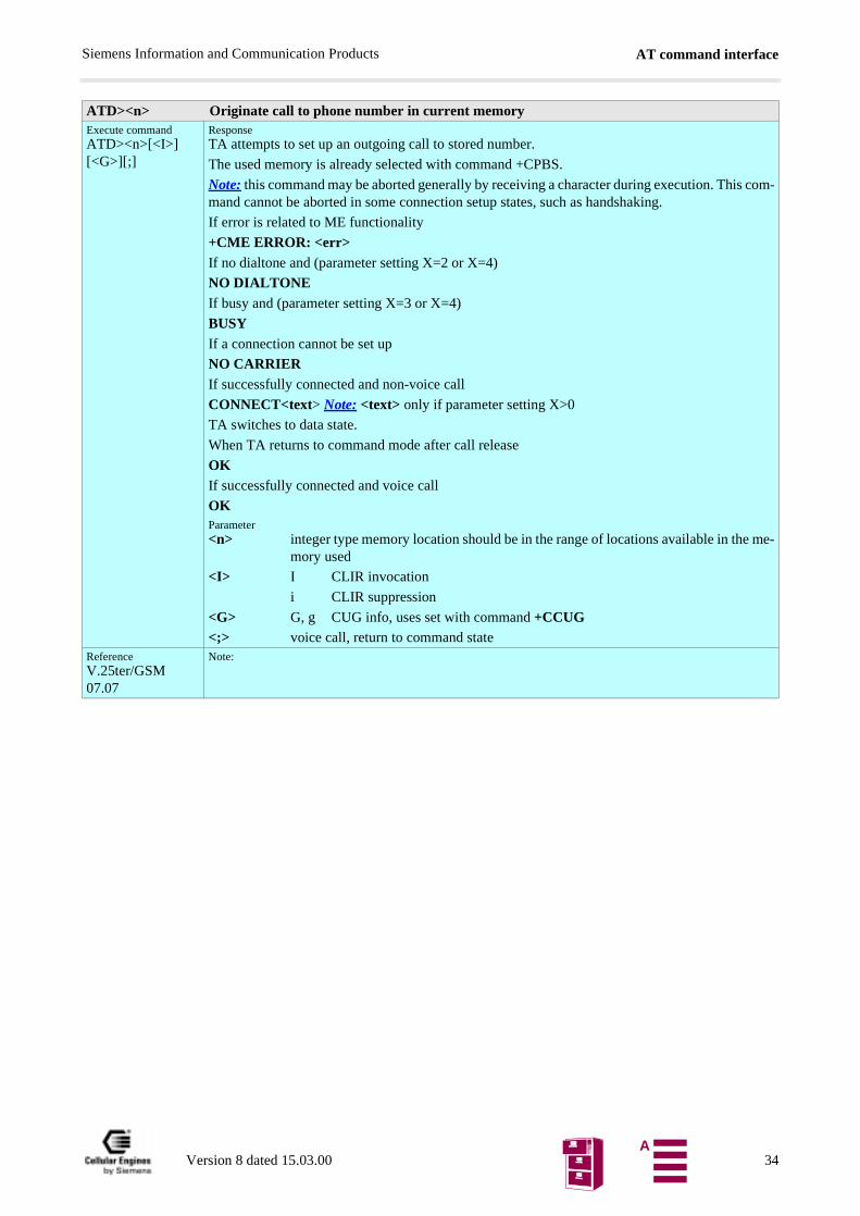
ATD><n> Originate call to phone number in current memoryExecute commandATD><n>[<I>][<G>][;]
ResponseTA attempts to set up an outgoing call to stored number.
The used memory is already selected with command +CPBS.
Note: this command may be aborted generally by receiving a character during execution. This com-mand cannot be aborted in some connection setup states, such as handshaking.
If error is related to ME functionality
+CME ERROR: <err>If no dialtone and (parameter setting X=2 or X=4)
NO DIALTONE If busy and (parameter setting X=3 or X=4)
BUSYIf a connection cannot be set up
NO CARRIERIf successfully connected and non-voice call
CONNECT<text> Note: <text> only if parameter setting X>0
TA switches to data state.
When TA returns to command mode after call release
OKIf successfully connected and voice call
OKParameter<n> integer type memory location should be in the range of locations available in the me-
mory used
<I> I CLIR invocation
i CLIR suppression
<G> G, g CUG info, uses set with command +CCUG<;> voice call, return to command state
ReferenceV.25ter/GSM 07.07
Note:
Version 8 dated 15.03.00 34A
AT command interfaceSiemens Information and Communication Products
ATD><str> Originate call to phone number in memory with corresponding alphanum. fieldExecute commandATD><str>[I][G][;]
ResponseTA attempts to set up an outgoing call to stored number.
All available memories are searched for the entry <str>, except LD, MC, RC.
Note 1: The search string has to be identical to the complete string in the phonebook.
Note 2: This command may be aborted generally by receiving a character during execution. This command cannot be aborted in some connection setup states, such as handshaking.
If error is related to ME functionality
+CME ERROR: <err>If no dialtone and (parameter setting X=2 or X=4)
NO DIALTONE If busy and (parameter setting X=3 or X=4)
BUSYIf a connection cannot be set up
NO CARRIERIf successfully connected and non-voice call
CONNECT<text> Note: <text> only if parameter setting X>0
TA switches to data state.
When TA returns to command mode after call release
OKIf successfully connected and voice call
OKParameter<str> string type value ("x"), which should equal an alphanumeric field in at least one phonebook entry in the searched memories
<I> I CLIR activation
i CLIR suppression
<G> G, g CUG info, uses set with command +CCUG
<;> voice call, return to command stateReferenceV.25ter/GSM 07.07
Note
Version 8 dated 15.03.00 35A
AT command interfaceSiemens Information and Communication Products
ATDI Mobile originated call to dialable ISDN number <n>Execute commandATDI<n>[;]
ResponseTA attempts to set up an outgoing call to ISDN number.
Note: this command may be aborted generally by receiving a character during execution. This com-mand cannot be aborted in some connection setup states, such as handshaking.
If no dialtone and (parameter setting X=2 or X=4)
NO DIALTONE If busy and (parameter setting X=3 or X=4)
BUSYIf a connection cannot be set up
NO CARRIERIf successfully connected and non-voice call
CONNECT<text> Note: <text> only if parameter setting X>0
TA switches to data state.
When TA returns to command mode after call release
OKIf successfully connected and voice call
OKParameter<n> [+]<d> phone number
string with maximum length of 20 characters
+ international dialling format
<d> ISDN number
string of digits: +,0-9, A, B, C
<;> voice callReferenceSiemens
Note
Version 8 dated 15.03.00 36A
AT command interfaceSiemens Information and Communication Products
ATDL Redial last telephone number usedExecute commandATDL[;]
ResponseTA attempts to set up an outgoing call to stored number.
Note: this command may be aborted generally by receiving a character during execution. This com-mand cannot be aborted in some connection setup states, such as handshaking.
If there is no last number or number is not valid:
+CME ERRORor:
If no dialtone and (parameter setting X=2 or X=4)
NO DIALTONE If busy and (parameter setting X=3 or X=4)
BUSY If a connection cannot be set up
NO CARRIER If successfully connected and non-voice call
CONNECT<text> Note: <text> only if parameter setting X>0
TA switches to data state.
When TA returns to command mode after call release
OK If successfully connected and voice call
OKParameter<;> voice call
ReferenceSiemens
Note
Version 8 dated 15.03.00 37A
AT command interfaceSiemens Information and Communication Products
ATDS Dial stored phone number in ME-phonebookExecute commandATDS=<n>[;]
ResponseTA attempts to set up an outgoing call to stored number.
The phone number is searched in ME-phonebook "ME".
Note: this command may be aborted generally by receiving a character during execution. This com-mand cannot be aborted in some connection setup states, such as handshaking.
If there is no valid number
+CME ERROR: <err>or
If no dialtone and (parameter setting X=2 or X=4)
NO DIALTONE If busy and (parameter setting X=3 or X=4)
BUSY If a connection cannot be set up
NO CARRIER If successfully connected and non-voice call
CONNECT<text> Note: <text> only if parameter setting X>0
TA switches to data state.
When TA returns to command mode after call release
OK If successfully connected and voice call
OKParameter<n> address of stored phone number
<;> voice callReferenceSiemens
Note
ATE Enable command echoSet commandATE[<value>]
ResponseThis setting determines whether or not the TA echoes characters received from TE during com-mand state.
OKParameter<value> 0 Echo mode off
1 Echo mode on
ReferenceV.25ter
Note
ATH Disconnect existing connectionExecute commandATH[n]
ResponseDisconnect existing call by local TE from command line and terminate call
OKNote: OK is issued after circuit 109 (DCD) is turned off (if it was previously on).Parameter<n> 0 disconnect from line and terminate call
ReferenceV.25ter
Note
Version 8 dated 15.03.00 38A
AT command interfaceSiemens Information and Communication Products
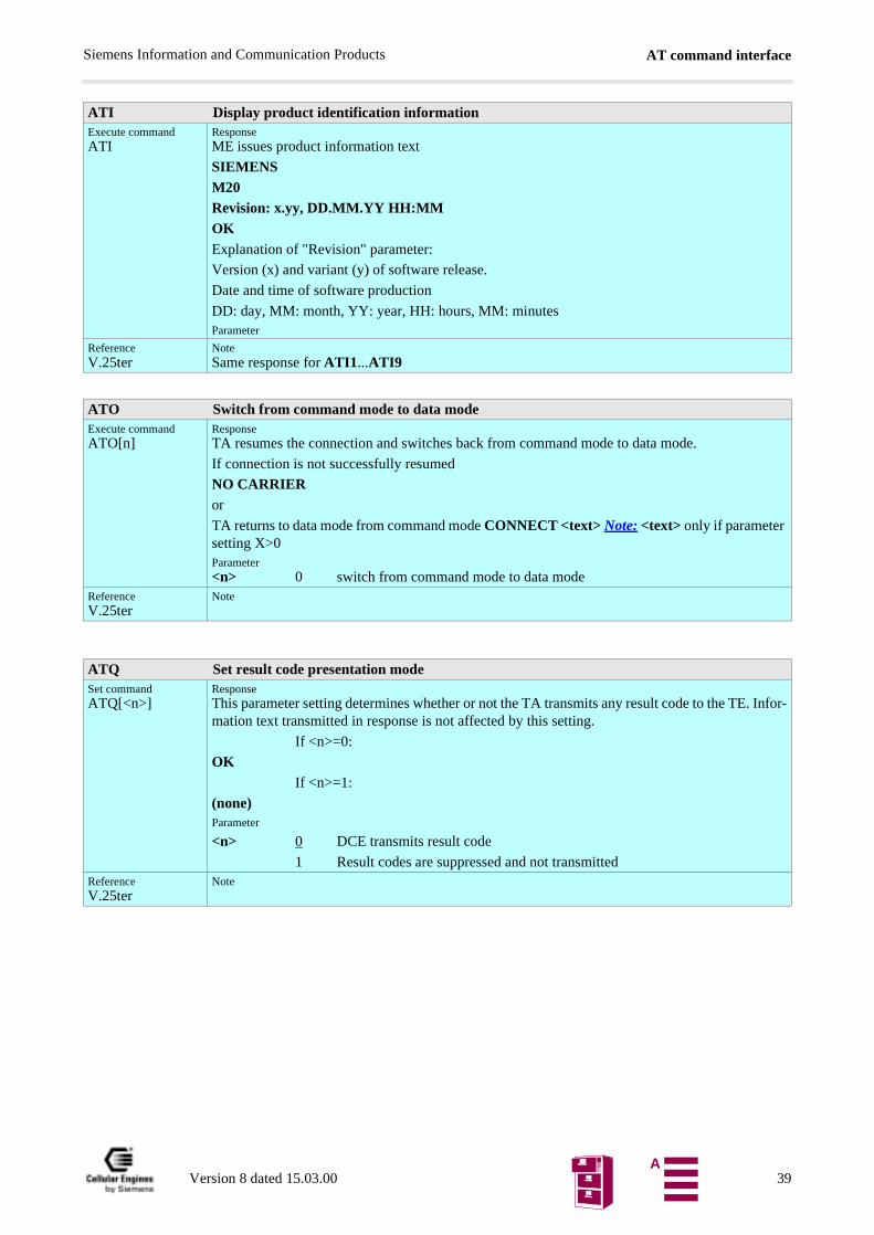
ATI Display product identification informationExecute commandATI
ResponseME issues product information text
SIEMENSM20Revision: x.yy, DD.MM.YY HH:MMOKExplanation of "Revision" parameter:
Version (x) and variant (y) of software release.
Date and time of software production
DD: day, MM: month, YY: year, HH: hours, MM: minutesParameter
ReferenceV.25ter
NoteSame response for ATI1...ATI9
ATO Switch from command mode to data modeExecute commandATO[n]
ResponseTA resumes the connection and switches back from command mode to data mode.
If connection is not successfully resumed
NO CARRIERor
TA returns to data mode from command mode CONNECT <text> Note: <text> only if parameter setting X>0Parameter<n> 0 switch from command mode to data mode
ReferenceV.25ter
Note
ATQ Set result code presentation modeSet commandATQ[<n>]
ResponseThis parameter setting determines whether or not the TA transmits any result code to the TE. Infor-mation text transmitted in response is not affected by this setting.
If <n>=0:
OKIf <n>=1:
(none)Parameter
<n> 0 DCE transmits result code
1 Result codes are suppressed and not transmittedReferenceV.25ter
Note
Version 8 dated 15.03.00 39A
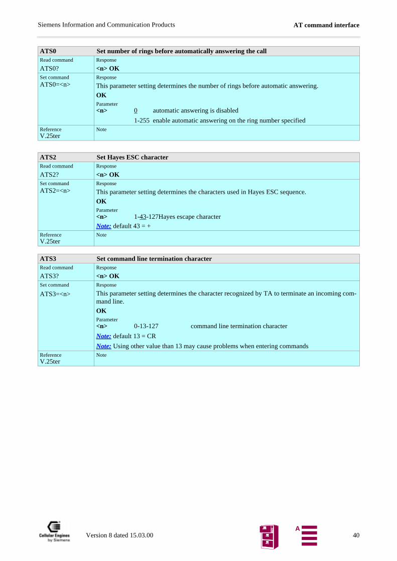
AT command interfaceSiemens Information and Communication Products
ATS0 Set number of rings before automatically answering the callRead command
ATS0?Response
<n> OKSet command
ATS0=<n>Response
This parameter setting determines the number of rings before automatic answering.
OKParameter<n> 0 automatic answering is disabled
1-255 enable automatic answering on the ring number specifiedReferenceV.25ter
Note
ATS2 Set Hayes ESC character Read command
ATS2?Response
<n> OKSet command
ATS2=<n>Response
This parameter setting determines the characters used in Hayes ESC sequence.
OKParameter<n> 1-43-127Hayes escape character
Note: default 43 = +ReferenceV.25ter
Note
ATS3 Set command line termination characterRead command
ATS3?Response
<n> OKSet command
ATS3=<n>
Response
This parameter setting determines the character recognized by TA to terminate an incoming com-mand line.
OKParameter<n> 0-13-127 command line termination character
Note: default 13 = CR
Note: Using other value than 13 may cause problems when entering commandsReferenceV.25ter
Note
Version 8 dated 15.03.00 40A
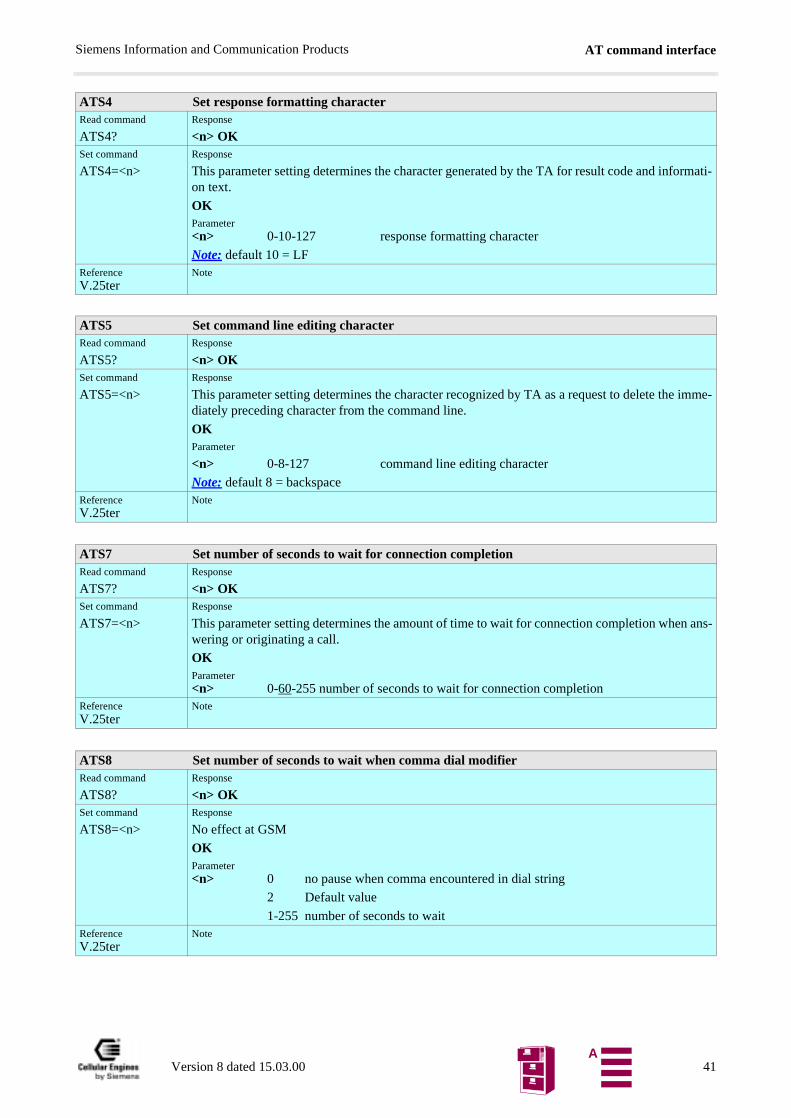
AT command interfaceSiemens Information and Communication Products
ATS4 Set response formatting characterRead command
ATS4?Response
<n> OKSet command
ATS4=<n>Response
This parameter setting determines the character generated by the TA for result code and informati-on text.
OKParameter<n> 0-10-127 response formatting character
Note: default 10 = LFReferenceV.25ter
Note
ATS5 Set command line editing characterRead command
ATS5?Response
<n> OKSet command
ATS5=<n>Response
This parameter setting determines the character recognized by TA as a request to delete the imme-diately preceding character from the command line.
OKParameter
<n> 0-8-127 command line editing character
Note: default 8 = backspaceReferenceV.25ter
Note
ATS7 Set number of seconds to wait for connection completionRead command
ATS7?Response
<n> OKSet command
ATS7=<n>Response
This parameter setting determines the amount of time to wait for connection completion when ans-wering or originating a call.
OKParameter<n> 0-60-255 number of seconds to wait for connection completion
ReferenceV.25ter
Note
ATS8 Set number of seconds to wait when comma dial modifierRead command
ATS8?Response
<n> OKSet command
ATS8=<n>Response
No effect at GSM
OKParameter<n> 0 no pause when comma encountered in dial string
2 Default value
1-255 number of seconds to waitReferenceV.25ter
Note
Version 8 dated 15.03.00 41A
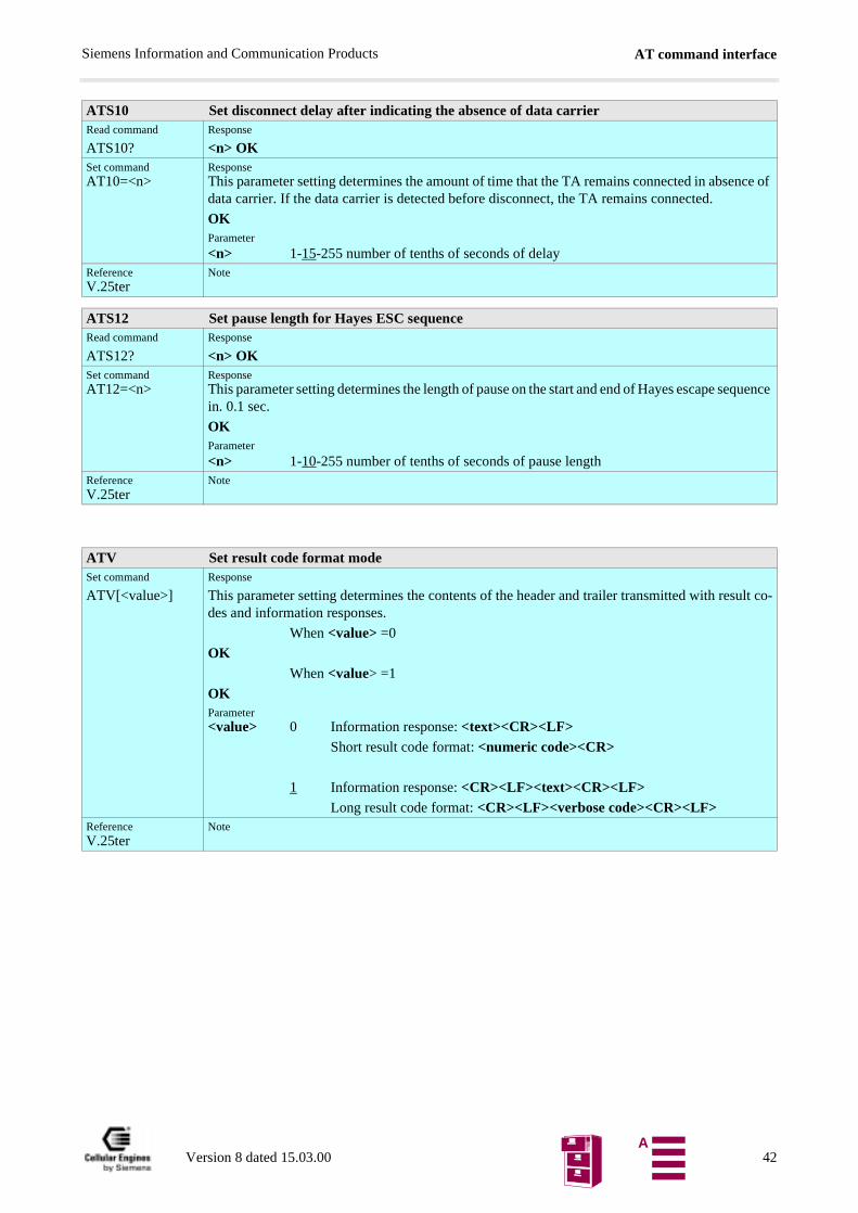
AT command interfaceSiemens Information and Communication Products
ATS10 Set disconnect delay after indicating the absence of data carrierRead command
ATS10?Response
<n> OKSet commandAT10=<n>
ResponseThis parameter setting determines the amount of time that the TA remains connected in absence of data carrier. If the data carrier is detected before disconnect, the TA remains connected.
OKParameter
<n> 1-15-255 number of tenths of seconds of delayReferenceV.25ter
Note
ATS12 Set pause length for Hayes ESC sequenceRead command
ATS12?Response
<n> OKSet commandAT12=<n>
ResponseThis parameter setting determines the length of pause on the start and end of Hayes escape sequence in. 0.1 sec.
OKParameter
<n> 1-10-255 number of tenths of seconds of pause lengthReferenceV.25ter
Note
ATV Set result code format modeSet command
ATV[<value>]Response
This parameter setting determines the contents of the header and trailer transmitted with result co-des and information responses.
When <value> =0
OKWhen <value> =1
OKParameter<value> 0 Information response: <text><CR><LF>
Short result code format: <numeric code><CR>
1 Information response: <CR><LF><text><CR><LF>Long result code format: <CR><LF><verbose code><CR><LF>
ReferenceV.25ter
Note
Version 8 dated 15.03.00 42A
AT command interfaceSiemens Information and Communication Products
ATX Set CONNECT result code format and call monitoringSet command
ATX[<value>]Response
This parameter setting determines whether or not the TA detected the presence of dial tone and busy signal and whether or not TA transmits particular result codes
OKParameter<value> 0 CONNECT result code only returned, dial tone and busy detection
are both disabled
1 CONNECT<text> result code only returned, dial tone and busy detection are both disabled
2 CONNECT<text> result code returned, dial tone detection is enabled, busy detection is disabled
3 CONNECT<text> result code returned, dial tone detection is disabled, busy detection is enabled
4 CONNECT<text> result code returned, dial tone and busy detectionare both enabled
5 same as 4, in addition intermediate result codes ^SALERTING, ^SQUEUED, ^SBUSY and ^SNO CARRIER are sent if necessary
ReferenceV.25ter
Note
ATZ Set all current parameters to user defined profileExecute command
ATZ[<value>]Response
TA sets all current parameters to the user-defined profile.
Note 1: The user defined profile is stored in non-volatile memory.
Note 2: If invalid, the user-profile will be reset to the factory default profile.
Note 3: Any additional commands on the same command line are ignored.
Note 4: A delay of 300ms is needed before next command is sent, otherwise "OK" response may be corrupted.
OKParameter<value> 0 Reset to profile number 0
ReferenceV.25ter
Note
There has to be a pause of at least 300ms after the OK, before the next command is entered.
AT&C Set circuit Data Carrier Detect (DCD) function modeSet commandAT&C[<value>]
ResponseThis parameter determines how the state of circuit 109 (DCD) relates to the detection of received line signal from the distant end.
OKParameter<value> 0 DCD line is always ON
1 DCD line is ON only in the presence of data carrierReferenceV.25ter
Note
Version 8 dated 15.03.00 43A
AT command interfaceSiemens Information and Communication Products
AT&D Set circuit Data Terminal Ready (DTR) function modeSet commandAT&D[<value>]
Response
This parameter determines how the TA responds when circuit 108/2 (DTR) is changed from ON to OFF during data mode.
OKParameter<value> 0 TA ignores status on DTR
1 ON->OFF on DTR: change to command mode while retaining the connected call
2 ON->OFF on DTR: disconnect call, change to command mode. During DTR state = OFF is auto-answer off.
ReferenceV.25ter
NoteM1: <value> 0-3
AT&F Set all current parameters to manufacturer defaultsExecute commandAT&F[value]
ResponseTA sets all current parameters to the manufacturer defined profile.
Note: 1) When using AT&F(CR) alone a delay of 300ms needed before next command (AT...) issent. Otherwise "OK" response may be corrupted.
2) No restrictions of use of "&F" within a command string. (e.g.: AT&Fs0=1&W+cbst=7,0,1)
3) A delay of 300ms is needed before next command ist sent, otherwise "OK" response may be corrupted.
OKParameter<value> 0 set all TA parameters to manufacturer defaults
ReferenceV.25ter
NoteThere has to be a pause of at least 300ms after the OK, before the next command is entered.
AT&S Set circuit Data Set Ready (DSR) function modeSet commandAT&S<value>
ResponseThis parameter determines how the TA sets circuit 107 (DSR) depending on the communication state of the TA interfacing TE.
OKParameter<value> 0 DSR always on
1 TA in command mode: DSR is OFF
TA in data mode: DSR is ONReferenceV.25ter, +IDSR
Note
Version 8 dated 15.03.00 44A
AT command interfaceSiemens Information and Communication Products
AT&V Display current configurationExecute commandAT&V[<n>]
ResponseTA returns the current parameter setting.
ACTIVE PROFILE :E1 L0 M0 Q0 V1 X4;S0:1 S2:43 S3:13 S4:10 S5:8 S6:2 S7:60 S8:2 S10:15 S12:10 S13:60 S1:0+CBST: 7,0,1+CRLP: 61,61,48,6,1,3+CRC: 0+CR: 1+FCLASS: 0+IFC: 2,2+ICF: 3,3+DR: 1+CMGF: 0+CSDH: 1+CNMI: 2,1,0,0,0+ILRR: 0+IPR: 19200+DS: 0,0,512,6+CMEE: 2^SMGO: 0+CSMS: 0^SACM: 0^SCKS: 0+CREG: 2+CCUG: 0,0,0+CLIP: 0+COLP: 0+CCWA: 0+CAOC: 1+CLIR: 0+COPS: 0
OKParameter<n> 0 profile number
Reference Note
AT&W Store current parameter to user defined profileExecute commandAT&W[<n>]
ResponseTA stores the current parameter setting in the user-defined profile.
Note1: the user defined profile is stored in non-volatile memory.
OKParameter<n> 0 profile number to store to
Reference Note
Version 8 dated 15.03.00 45A
AT command interfaceSiemens Information and Communication Products
AT&Z Store telephone number in SIM fixdialling memory "FD"Execute commandAT&Z<n>=<x>
ResponseTA stores a dial string in ME non volatile memory "ME" at memory index <n>.
Only digits and the characters "i" and "+" are stored.
OKIf error is related to ME functionality:
+CME ERROR: <err>Parameter<n> memory index
<x> [+]<d> phone number
string with maximum 20 characters
+ international dialling format
<d> ISDN number
string of digits: +, 0-9, A, B, CReferenceSiemens
NoteA non leading + will not be stored, Letter A will be changed to + (A −−> +)
AT%D Automatic dialling phone number in mem. "ME" index "1" with DTRExecute commandAT%D<n>[;]
ResponseTA attempts to set up an outgoing call to stored number.
TA reads the phone number in "ME" memory with index "1" and calls this
number.
If no dialtone and (parameter setting X=2 or X=4)
NO DIALTONE If busy and (parameter setting X=3 or X=4)
BUSYIf a connection cannot be set up
NO CARRIERIf successfully connected and non-voice call
CONNECT<text> Note: <text> only if parameter setting X>0
TA switches to data state.
When TA returns to command mode after call release
OKIf successfully connected and voice call
OKParameter<n> 0 TA ignores status on DTR
1 OFF->ON on DTR: TA dials telephone number in memory ´1´ ReferenceSiemens
Note
Version 8 dated 15.03.00 46A
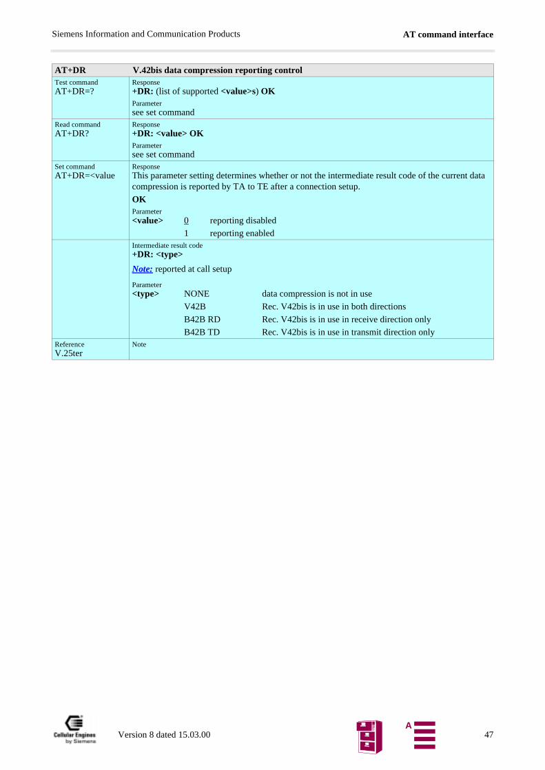
AT command interfaceSiemens Information and Communication Products
AT+DR V.42bis data compression reporting controlTest commandAT+DR=?
Response+DR: (list of supported <value>s) OKParametersee set command
Read commandAT+DR?
Response+DR: <value> OKParametersee set command
Set commandAT+DR=<value
ResponseThis parameter setting determines whether or not the intermediate result code of the current data compression is reported by TA to TE after a connection setup.
OKParameter<value> 0 reporting disabled
1 reporting enabledIntermediate result code+DR: <type>
Note: reported at call setup
Parameter<type> NONE data compression is not in use
V42B Rec. V42bis is in use in both directions
B42B RD Rec. V42bis is in use in receive direction only
B42B TD Rec. V42bis is in use in transmit direction onlyReferenceV.25ter
Note
Version 8 dated 15.03.00 47A
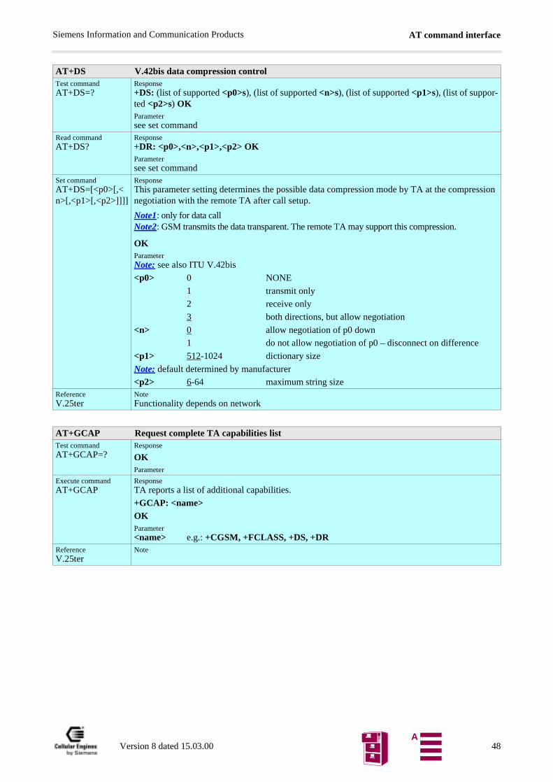
AT command interfaceSiemens Information and Communication Products
AT+DS V.42bis data compression controlTest commandAT+DS=?
Response+DS: (list of supported <p0>s), (list of supported <n>s), (list of supported <p1>s), (list of suppor-ted <p2>s) OKParametersee set command
Read commandAT+DS?
Response+DR: <p0>,<n>,<p1>,<p2> OKParametersee set command
Set commandAT+DS=[<p0>[,<n>[,<p1>[,<p2>]]]]
ResponseThis parameter setting determines the possible data compression mode by TA at the compression negotiation with the remote TA after call setup.
Note1: only for data callNote2: GSM transmits the data transparent. The remote TA may support this compression.
OKParameterNote: see also ITU V.42bis
<p0> 0 NONE
1 transmit only
2 receive only
3 both directions, but allow negotiation
<n> 0 allow negotiation of p0 down
1 do not allow negotiation of p0 – disconnect on difference
<p1> 512-1024 dictionary size
Note: default determined by manufacturer
<p2> 6-64 maximum string sizeReferenceV.25ter
NoteFunctionality depends on network
AT+GCAP Request complete TA capabilities listTest commandAT+GCAP=?
Response
OKParameter
Execute commandAT+GCAP
ResponseTA reports a list of additional capabilities.
+GCAP: <name>OKParameter<name> e.g.: +CGSM, +FCLASS, +DS, +DR
ReferenceV.25ter
Note
Version 8 dated 15.03.00 48A
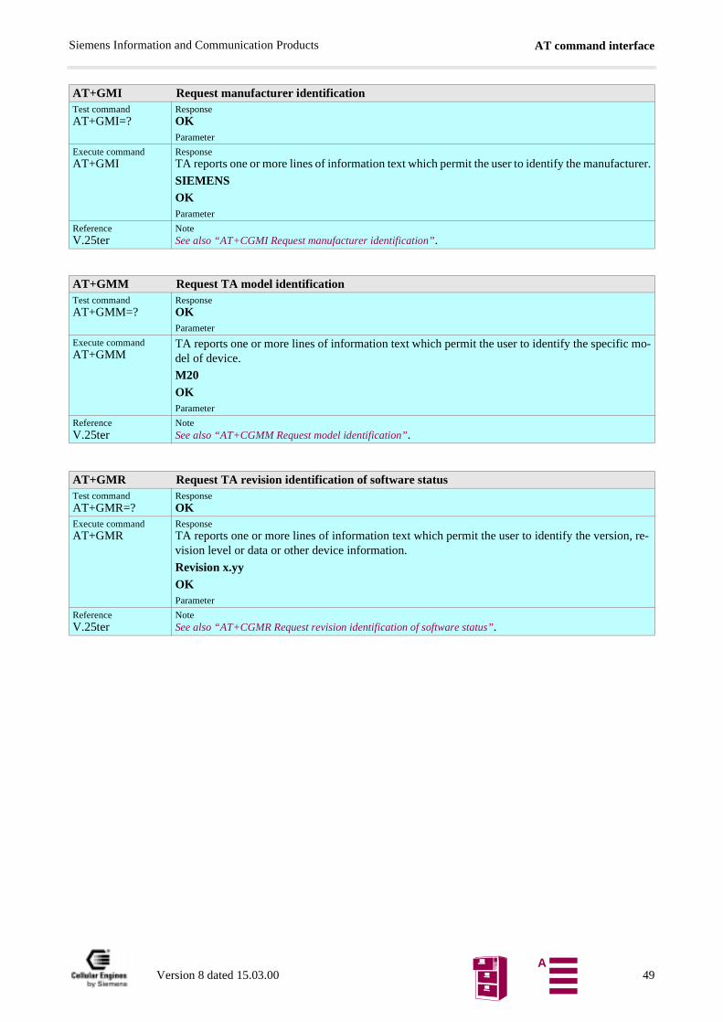
AT command interfaceSiemens Information and Communication Products
AT+GMI Request manufacturer identificationTest commandAT+GMI=?
ResponseOKParameter
Execute commandAT+GMI
ResponseTA reports one or more lines of information text which permit the user to identify the manufacturer.
SIEMENSOKParameter
ReferenceV.25ter
NoteSee also “AT+CGMI Request manufacturer identification”.
AT+GMM Request TA model identificationTest commandAT+GMM=?
ResponseOKParameter
Execute commandAT+GMM
TA reports one or more lines of information text which permit the user to identify the specific mo-del of device.
M20OKParameter
ReferenceV.25ter
NoteSee also “AT+CGMM Request model identification”.
AT+GMR Request TA revision identification of software statusTest commandAT+GMR=?
ResponseOK
Execute commandAT+GMR
ResponseTA reports one or more lines of information text which permit the user to identify the version, re-vision level or data or other device information.
Revision x.yyOKParameter
ReferenceV.25ter
NoteSee also “AT+CGMR Request revision identification of software status”.
Version 8 dated 15.03.00 49A
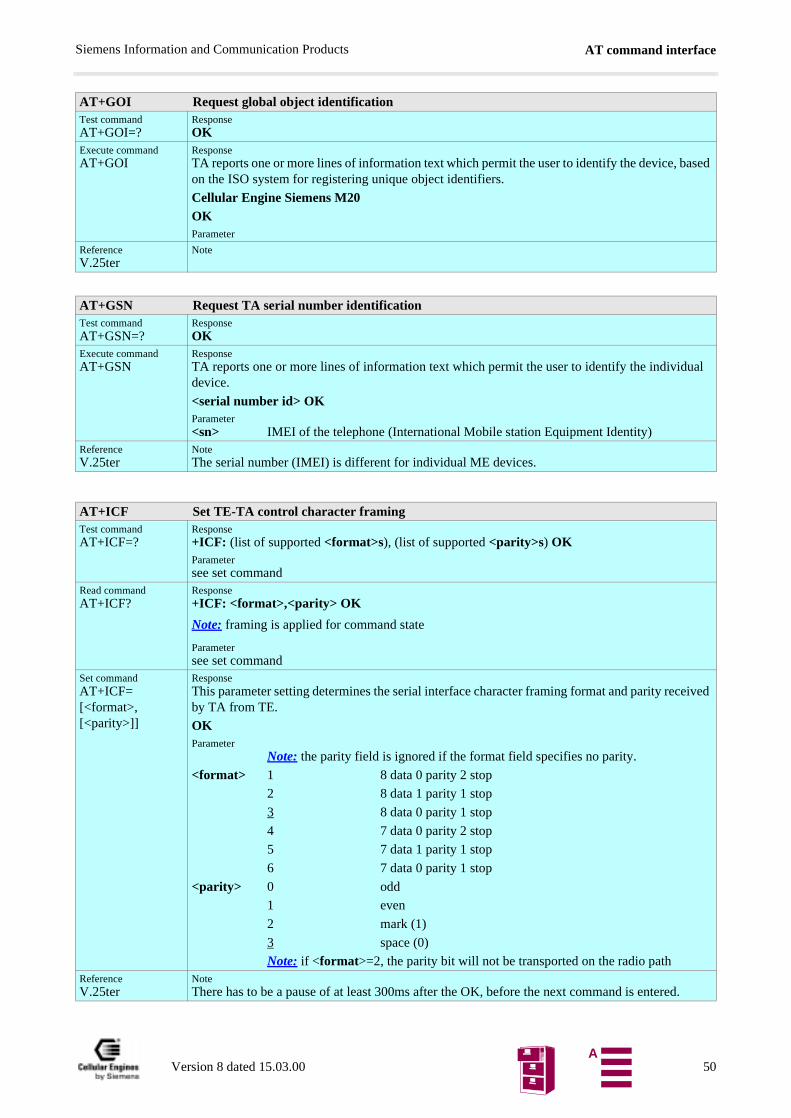
AT command interfaceSiemens Information and Communication Products
AT+GOI Request global object identificationTest commandAT+GOI=?
ResponseOK
Execute commandAT+GOI
ResponseTA reports one or more lines of information text which permit the user to identify the device, based on the ISO system for registering unique object identifiers.
Cellular Engine Siemens M20OKParameter
ReferenceV.25ter
Note
AT+GSN Request TA serial number identificationTest commandAT+GSN=?
ResponseOK
Execute commandAT+GSN
ResponseTA reports one or more lines of information text which permit the user to identify the individual device.
<serial number id> OKParameter<sn> IMEI of the telephone (International Mobile station Equipment Identity)
ReferenceV.25ter
NoteThe serial number (IMEI) is different for individual ME devices.
AT+ICF Set TE-TA control character framingTest commandAT+ICF=?
Response+ICF: (list of supported <format>s), (list of supported <parity>s) OKParametersee set command
Read commandAT+ICF?
Response+ICF: <format>,<parity> OK
Note: framing is applied for command state
Parametersee set command
Set commandAT+ICF=[<format>,[<parity>]]
ResponseThis parameter setting determines the serial interface character framing format and parity received by TA from TE.
OKParameter
Note: the parity field is ignored if the format field specifies no parity.
<format> 1 8 data 0 parity 2 stop
2 8 data 1 parity 1 stop
3 8 data 0 parity 1 stop
4 7 data 0 parity 2 stop
5 7 data 1 parity 1 stop
6 7 data 0 parity 1 stop
<parity> 0 odd
1 even
2 mark (1)
3 space (0)
Note: if <format>=2, the parity bit will not be transported on the radio pathReferenceV.25ter
NoteThere has to be a pause of at least 300ms after the OK, before the next command is entered.
Version 8 dated 15.03.00 50A
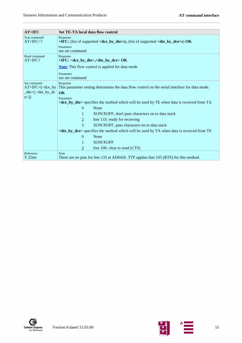
AT command interfaceSiemens Information and Communication Products
AT+IFC Set TE-TA local data flow controlTest commandAT+IFC=?
Response+IFC: (list of supported <dce_by_dte>s), (list of supported <dte_by_dce>s) OKParametersee set command
Read commandAT+IFC?
Response+IFC: <dce_by_dte>,<dte_by_dce> OK
Note: This flow control is applied for data mode
Parametersee set command
Set commandAT+IFC=[<dce_by_dte>[,<dte_by_dce>]]
ResponseThis parameter setting determines the data flow control on the serial interface for data mode.
OKParameter<dce_by_dte> specifies the method which will be used by TE when data is received from TA
0 None
1 XON/XOFF, don’t pass characters on to data stack
2 line 133: ready for receiving
3 XON/XOFF, pass characters on to data stack
<dte_by_dce> specifies the method which will be used by TA when data is received from TE
0 None
1 XON/XOFF
2 line 106: clear to send (CTS)ReferenceV.25ter
NoteThere are no pins for line 133 at AD6426. TTP applies line 105 (RTS) for this method.
Version 8 dated 15.03.00 51A
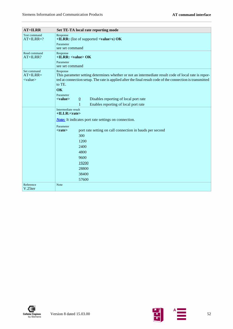
AT command interfaceSiemens Information and Communication Products
AT+ILRR Set TE-TA local rate reporting modeTest commandAT+ILRR=?
Response+ILRR: (list of supported <value>s) OKParametersee set command
Read commandAT+ILRR?
Response+ILRR: <value> OKParametersee set command
Set commandAT+ILRR=<value>
ResponseThis parameter setting determines whether or not an intermediate result code of local rate is repor-ted at connection setup. The rate is applied after the final result code of the connection is transmitted to TE.
OKParameter<value> 0 Disables reporting of local port rate
1 Enables reporting of local port rateIntermediate result+ILLR:<rate>
Note: It indicates port rate settings on connection.
Parameter<rate> port rate setting on call connection in bauds per second
300
1200
2400
4800
9600
19200
28800
38400
57600ReferenceV.25ter
Note
Version 8 dated 15.03.00 52A
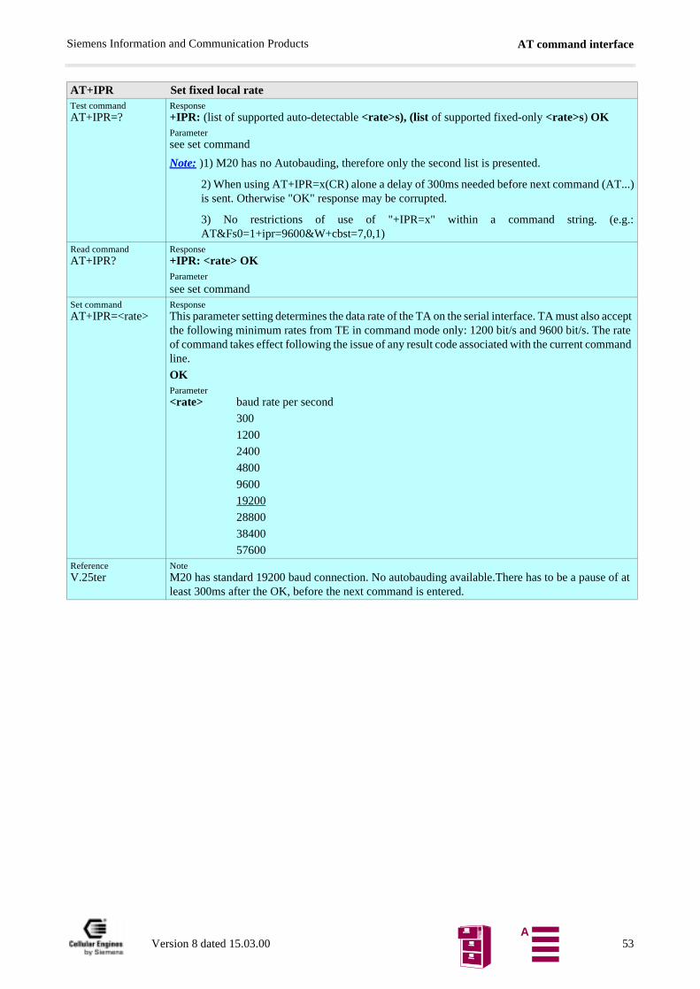
AT command interfaceSiemens Information and Communication Products
AT+IPR Set fixed local rateTest commandAT+IPR=?
Response+IPR: (list of supported auto-detectable <rate>s), (list of supported fixed-only <rate>s) OKParametersee set command
Note: )1) M20 has no Autobauding, therefore only the second list is presented.
2) When using AT+IPR=x(CR) alone a delay of 300ms needed before next command (AT...)is sent. Otherwise "OK" response may be corrupted.
3) No restrictions of use of "+IPR=x" within a command string. (e.g.:AT&Fs0=1+ipr=9600&W+cbst=7,0,1)
Read commandAT+IPR?
Response+IPR: <rate> OKParameter
see set commandSet commandAT+IPR=<rate>
ResponseThis parameter setting determines the data rate of the TA on the serial interface. TA must also accept the following minimum rates from TE in command mode only: 1200 bit/s and 9600 bit/s. The rate of command takes effect following the issue of any result code associated with the current command line.
OKParameter<rate> baud rate per second
300
1200
2400
4800
9600
19200
28800
38400
57600ReferenceV.25ter
NoteM20 has standard 19200 baud connection. No autobauding available.There has to be a pause of at least 300ms after the OK, before the next command is entered.
Version 8 dated 15.03.00 53A
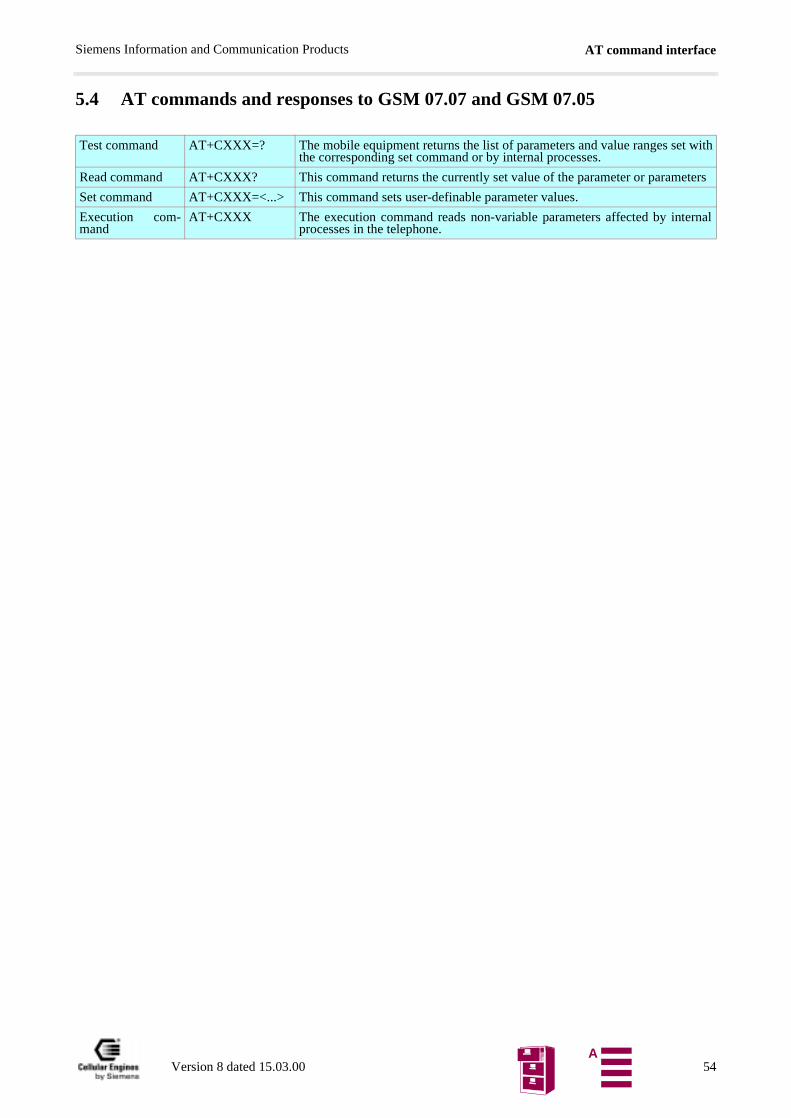
AT command interfaceSiemens Information and Communication Products
5.4 AT commands and responses to GSM 07.07 and GSM 07.05
Test command AT+CXXX=? The mobile equipment returns the list of parameters and value ranges set withthe corresponding set command or by internal processes.
Read command AT+CXXX? This command returns the currently set value of the parameter or parameters
Set command AT+CXXX=<...> This command sets user-definable parameter values.
Execution com-mand
AT+CXXX The execution command reads non-variable parameters affected by internalprocesses in the telephone.
Version 8 dated 15.03.00 54A
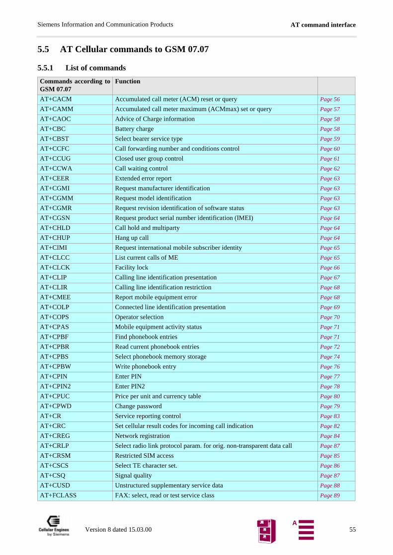
AT command interfaceSiemens Information and Communication Products
5.5 AT Cellular commands to GSM 07.07
5.5.1 List of commands
Commands according toGSM 07.07
Function
AT+CACM Accumulated call meter (ACM) reset or query Page 56
AT+CAMM Accumulated call meter maximum (ACMmax) set or query Page 57
AT+CAOC Advice of Charge information Page 58
AT+CBC Battery charge Page 58
AT+CBST Select bearer service type Page 59
AT+CCFC Call forwarding number and conditions control Page 60
AT+CCUG Closed user group control Page 61
AT+CCWA Call waiting control Page 62
AT+CEER Extended error report Page 63
AT+CGMI Request manufacturer identification Page 63
AT+CGMM Request model identification Page 63
AT+CGMR Request revision identification of software status Page 63
AT+CGSN Request product serial number identification (IMEI) Page 64
AT+CHLD Call hold and multiparty Page 64
AT+CHUP Hang up call Page 64
AT+CIMI Request international mobile subscriber identity Page 65
AT+CLCC List current calls of ME Page 65
AT+CLCK Facility lock Page 66
AT+CLIP Calling line identification presentation Page 67
AT+CLIR Calling line identification restriction Page 68
AT+CMEE Report mobile equipment error Page 68
AT+COLP Connected line identification presentation Page 69
AT+COPS Operator selection Page 70
AT+CPAS Mobile equipment activity status Page 71
AT+CPBF Find phonebook entries Page 71
AT+CPBR Read current phonebook entries Page 72
AT+CPBS Select phonebook memory storage Page 74
AT+CPBW Write phonebook entry Page 76
AT+CPIN Enter PIN Page 77
AT+CPIN2 Enter PIN2 Page 78
AT+CPUC Price per unit and currency table Page 80
AT+CPWD Change password Page 79
AT+CR Service reporting control Page 83
AT+CRC Set cellular result codes for incoming call indication Page 82
AT+CREG Network registration Page 84
AT+CRLP Select radio link protocol param. for orig. non-transparent data call Page 87
AT+CRSM Restricted SIM access Page 85
AT+CSCS Select TE character set. Page 86
AT+CSQ Signal quality Page 87
AT+CUSD Unstructured supplementary service data Page 88
AT+FCLASS FAX: select, read or test service class Page 89
Version 8 dated 15.03.00 55A
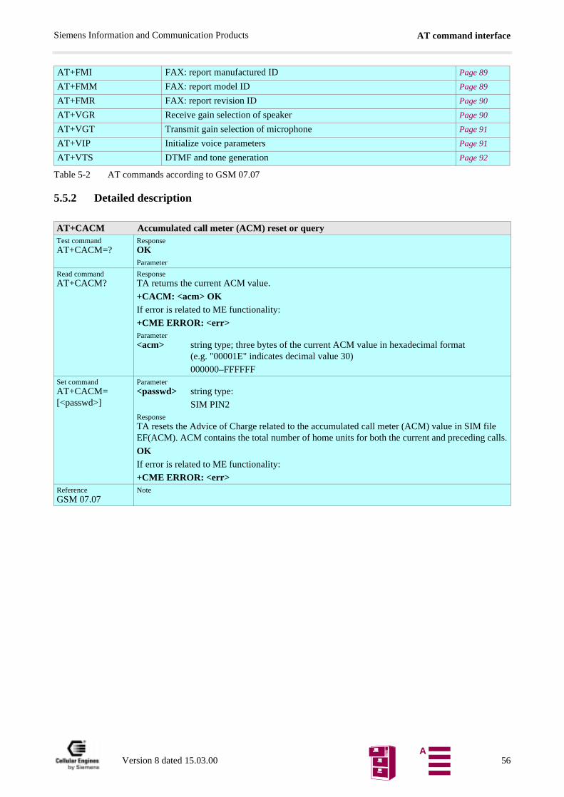
AT command interfaceSiemens Information and Communication Products
e alls.
Table 5-2 AT commands according to GSM 07.07
5.5.2 Detailed description
AT+FMI FAX: report manufactured ID Page 89
AT+FMM FAX: report model ID Page 89
AT+FMR FAX: report revision ID Page 90
AT+VGR Receive gain selection of speaker Page 90
AT+VGT Transmit gain selection of microphone Page 91
AT+VIP Initialize voice parameters Page 91
AT+VTS DTMF and tone generation Page 92
AT+CACM Accumulated call meter (ACM) reset or queryTest commandAT+CACM=?
ResponseOKParameter
Read commandAT+CACM?
ResponseTA returns the current ACM value.
+CACM: <acm> OKIf error is related to ME functionality:
+CME ERROR: <err>Parameter<acm> string type; three bytes of the current ACM value in hexadecimal format
(e.g. "00001E" indicates decimal value 30)
000000–FFFFFFSet commandAT+CACM=[<passwd>]
Parameter<passwd> string type:
SIM PIN2ResponseTA resets the Advice of Charge related to the accumulated call meter (ACM) value in SIM filEF(ACM). ACM contains the total number of home units for both the current and preceding c
OKIf error is related to ME functionality:
+CME ERROR: <err>ReferenceGSM 07.07
Note
Version 8 dated 15.03.00 56A
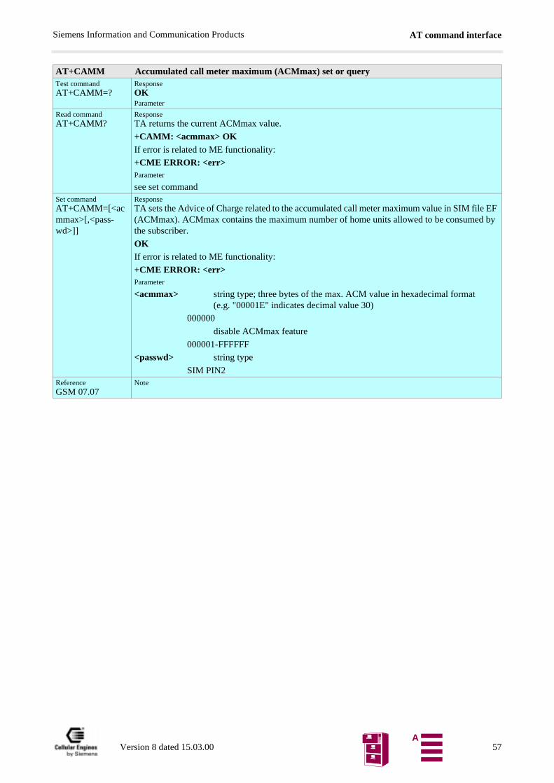
AT command interfaceSiemens Information and Communication Products
AT+CAMM Accumulated call meter maximum (ACMmax) set or queryTest commandAT+CAMM=?
ResponseOKParameter
Read commandAT+CAMM?
ResponseTA returns the current ACMmax value.
+CAMM: <acmmax> OKIf error is related to ME functionality:
+CME ERROR: <err>Parameter
see set commandSet commandAT+CAMM=[<acmmax>[,<pass-wd>]]
ResponseTA sets the Advice of Charge related to the accumulated call meter maximum value in SIM file EF (ACMmax). ACMmax contains the maximum number of home units allowed to be consumed by the subscriber.
OKIf error is related to ME functionality:
+CME ERROR: <err>Parameter
<acmmax> string type; three bytes of the max. ACM value in hexadecimal format (e.g. "00001E" indicates decimal value 30)
000000
disable ACMmax feature
000001-FFFFFF
<passwd> string type
SIM PIN2ReferenceGSM 07.07
Note
Version 8 dated 15.03.00 57A
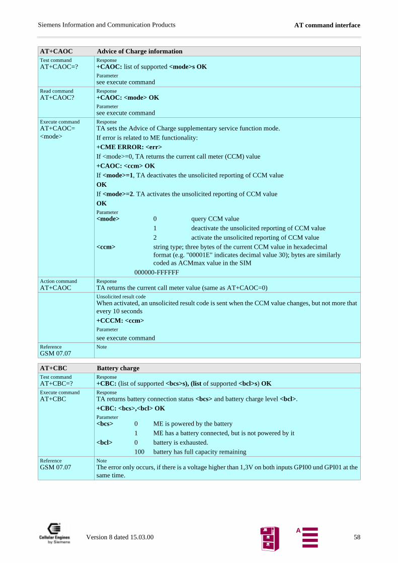
AT command interfaceSiemens Information and Communication Products
AT+CAOC Advice of Charge informationTest commandAT+CAOC=?
Response+CAOC: list of supported <mode>s OKParametersee execute command
Read commandAT+CAOC?
Response+CAOC: <mode> OKParametersee execute command
Execute commandAT+CAOC=<mode>
ResponseTA sets the Advice of Charge supplementary service function mode.
If error is related to ME functionality:
+CME ERROR: <err>If <mode>=0, TA returns the current call meter (CCM) value
+CAOC: <ccm> OKIf <mode>=1, TA deactivates the unsolicited reporting of CCM value
OKIf <mode>=2. TA activates the unsolicited reporting of CCM value
OKParameter<mode> 0 query CCM value
1 deactivate the unsolicited reporting of CCM value
2 activate the unsolicited reporting of CCM value
<ccm> string type; three bytes of the current CCM value in hexadecimalformat (e.g. "00001E" indicates decimal value 30); bytes are similarlycoded as ACMmax value in the SIM
000000-FFFFFFAction commandAT+CAOC
ResponseTA returns the current call meter value (same as AT+CAOC=0)Unsolicited result codeWhen activated, an unsolicited result code is sent when the CCM value changes, but not more that every 10 seconds
+CCCM: <ccm>Parameter
see execute commandReferenceGSM 07.07
Note
AT+CBC Battery chargeTest commandAT+CBC=?
Response+CBC: (list of supported <bcs>s), (list of supported <bcl>s) OK
Execute commandAT+CBC
ResponseTA returns battery connection status <bcs> and battery charge level <bcl>.
+CBC: <bcs>,<bcl> OKParameter<bcs> 0 ME is powered by the battery
1 ME has a battery connected, but is not powered by it
<bcl> 0 battery is exhausted.
100 battery has full capacity remainingReferenceGSM 07.07
NoteThe error only occurs, if there is a voltage higher than 1,3V on both inputs GPI00 und GPI01 at the same time.
Version 8 dated 15.03.00 58A
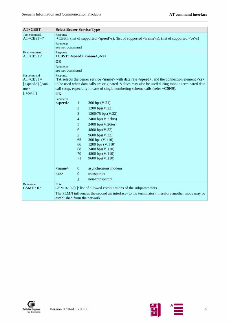
AT command interfaceSiemens Information and Communication Products
AT+CBST Select Bearer Service TypeTest commandAT+CBST=?
Response +CBST: (list of supported <speed>s), (list of supported <name>s), (list of supported <ce>s)Parametersee set command
Read commandAT+CBST?
Response+CBST: <speed>,<name>,<ce> OKParametersee set command
Set commandAT+CBST=[<speed>] [,<na-me>[,<ce>]]]
Response TA selects the bearer service <name> with data rate <speed>, and the connection element <ce> to be used when data calls are originated. Values may also be used during mobile terminated data call setup, especially in case of single numbering scheme calls (refer +CSNS).
OKParameter<speed> 1 300 bps(V.21)
2 1200 bps(V.22)
3 1200/75 bps(V.23)
4 2400 bps(V.22bis)
5 2400 bps(V.26ter)
6 4800 bps(V.32)
7 9600 bps(V.32)65 300 bps (V.110)66 1200 bps (V.110)68 2400 bps(V.110)70 4800 bps(V.110)71 9600 bps(V.110)
<name> 0 asynchronous modem
<ce> 0 transparent
1 non-transparentReferenceGSM 07.07
NoteGSM 02.02[1]: list of allowed combinations of the subparameters.
The PLMN influences the second air interface (to the terminator), therefore another mode may be established from the network.
Version 8 dated 15.03.00 59A
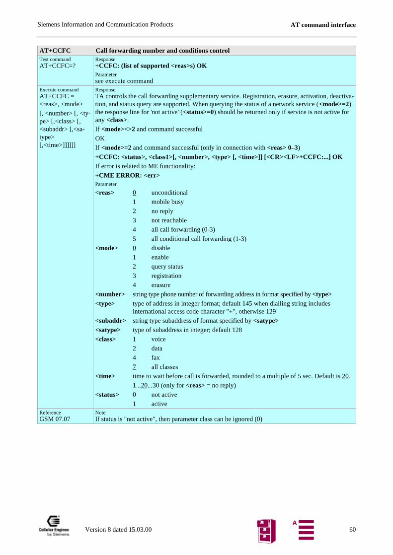
AT command interfaceSiemens Information and Communication Products
AT+CCFC Call forwarding number and conditions controlTest commandAT+CCFC=?
Response+CCFC: (list of supported <reas>s) OKParametersee execute command
Execute commandAT+CCFC = <reas>, <mode>
[, <number> [, <ty-pe> [,<class> [, <subaddr> [,<sa-type> [,<time>]]]]]]
ResponseTA controls the call forwarding supplementary service. Registration, erasure, activation, deactiva-tion, and status query are supported. When querying the status of a network service (<mode>=2) the response line for ’not active’ (<status>=0) should be returned only if service is not active for any <class>.
If <mode><>2 and command successful
OK
If <mode>=2 and command successful (only in connection with <reas> 0–3)+CCFC: <status>, <class1>[, <number>, <type> [, <time>]] [<CR><LF>+CCFC:...] OKIf error is related to ME functionality:
+CME ERROR: <err>Parameter
<reas> 0 unconditional
1 mobile busy
2 no reply
3 not reachable
4 all call forwarding (0-3)
5 all conditional call forwarding (1-3)
<mode> 0 disable
1 enable
2 query status
3 registration
4 erasure
<number> string type phone number of forwarding address in format specified by <type><type> type of address in integer format; default 145 when dialling string includes
international access code character "+", otherwise 129
<subaddr> string type subaddress of format specified by <satype><satype> type of subaddress in integer; default 128
<class> 1 voice
2 data
4 fax
7 all classes
<time> time to wait before call is forwarded, rounded to a multiple of 5 sec. Default is 20.
1...20...30 (only for <reas> = no reply)
<status> 0 not active
1 activeReferenceGSM 07.07
NoteIf status is "not active", then parameter class can be ignored (0)
Version 8 dated 15.03.00 60A
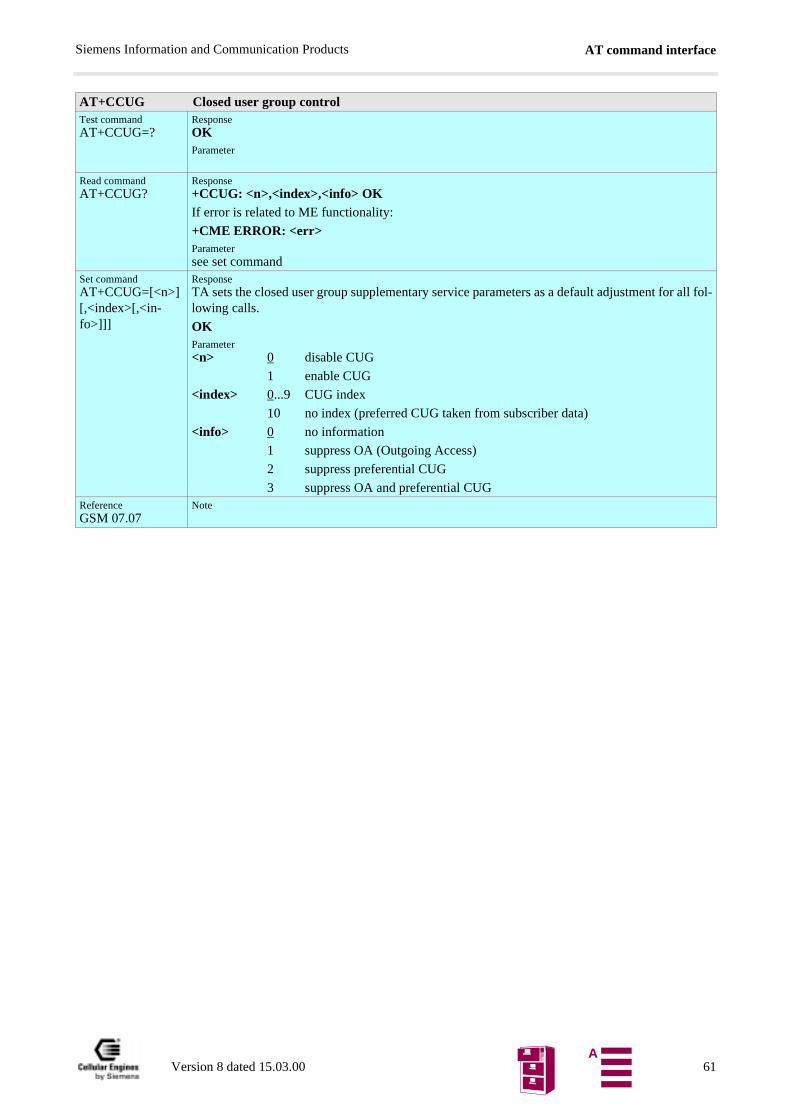
AT command interfaceSiemens Information and Communication Products
AT+CCUG Closed user group controlTest commandAT+CCUG=?
ResponseOKParameter
Read commandAT+CCUG?
Response+CCUG: <n>,<index>,<info> OKIf error is related to ME functionality:
+CME ERROR: <err>Parametersee set command
Set commandAT+CCUG=[<n>] [,<index>[,<in-fo>]]]
ResponseTA sets the closed user group supplementary service parameters as a default adjustment for all fol-lowing calls.
OKParameter<n> 0 disable CUG
1 enable CUG
<index> 0...9 CUG index
10 no index (preferred CUG taken from subscriber data)
<info> 0 no information
1 suppress OA (Outgoing Access)
2 suppress preferential CUG
3 suppress OA and preferential CUGReferenceGSM 07.07
Note
Version 8 dated 15.03.00 61A
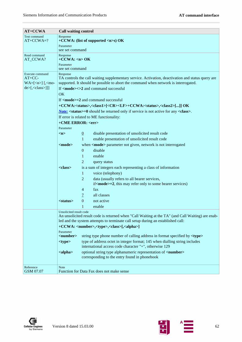
AT command interfaceSiemens Information and Communication Products
AT+CCWA Call waiting controlTest commandAT+CCWA=?
Response+CCWA: (list of supported <n>s) OKParametersee set command
Read commandAT_CCWA?
Response+CCWA: <n> OKParametersee set command
Execute commandAT+CC-WA=[<n>] [,<mo-de>[,<class>]]]
ResponseTA controls the call waiting supplementary service. Activation, deactivation and status query are supported. It should be possible to abort the command when network is interrogated.
If <mode><>2 and command successful
OK
If <mode>=2 and command successful
+CCWA:<status>,<class1>[<CR><LF>+CCWA:<status>,<class2>[...]] OKNote: <status>=0 should be returned only if service is not active for any <class>.
If error is related to ME functionality:
+CME ERROR: <err>Parameter
<n> 0 disable presentation of unsolicited result code
1 enable presentation of unsolicited result code
<mode> when <mode> parameter not given, network is not interrogated
0 disable
1 enable
2 query status
<class> is a sum of integers each representing a class of information
1 voice (telephony)
2 data (usually refers to all bearer services,if<mode>=2, this may refer only to some bearer services)
4 fax
7 all classes
<status> 0 not active
1 enableUnsolicited result codeAn unsolicited result code is returned when "Call Waiting at the TA" (and Call Waiting) are enab-led and the system attempts to terminate call setup during an established call:
+CCWA: <number>,<type>,<class>[,<alpha>]Parameter<number> string type phone number of calling address in format specified by <type><type> type of address octet in integer format; 145 when dialling string includes
international access code character "+", otherwise 129
<alpha> optional string type alphanumeric representation of <number> corresponding to the entry found in phonebook
ReferenceGSM 07.07
NoteFunction for Data Fax does not make sense
Version 8 dated 15.03.00 62A

AT command interfaceSiemens Information and Communication Products
AT+CEER Extended error reportTest commandAT+CEER=?
ResponseOK
Execute commandAT+CEER
ResponseTA returns an extended report of the reason for the last call release.
+CEER: <report> OKParameter<report> Reason for last call release as number code
ReferenceGSM 07.07
Note
AT+CGMI Request manufacturer identificationTest commandAT+CGMI=?
ResponseOK
Execute commandAT+CGMI
ResponseTA returns manufacturer identification text.
SIEMENSParameter<manufacturer>
ReferenceGSM 07.07
NoteSee also “AT+GMI Request manufacturer identification”.
AT+CGMM Request model identificationTest commandAT+CGMM=?
ResponseOK
Execute commandAT+CGMM
ResponseTA returns product model identification text.
M20OKParameter<model>
ReferenceGSM 07.07
NoteSee also “AT+GMM Request TA model identification”.
AT+CGMR Request revision identification of software statusTest commandAT+CGMR=?
ResponseOK
Execute commandAT+CGMR
ResponseTA returns product software version identification text.
<revision> x.yyOKParameterRevision x: version, yy: variant of software
ReferenceGSM 07.07
NoteSee also “AT+GMR Request TA revision identification of software status”.
Version 8 dated 15.03.00 63A
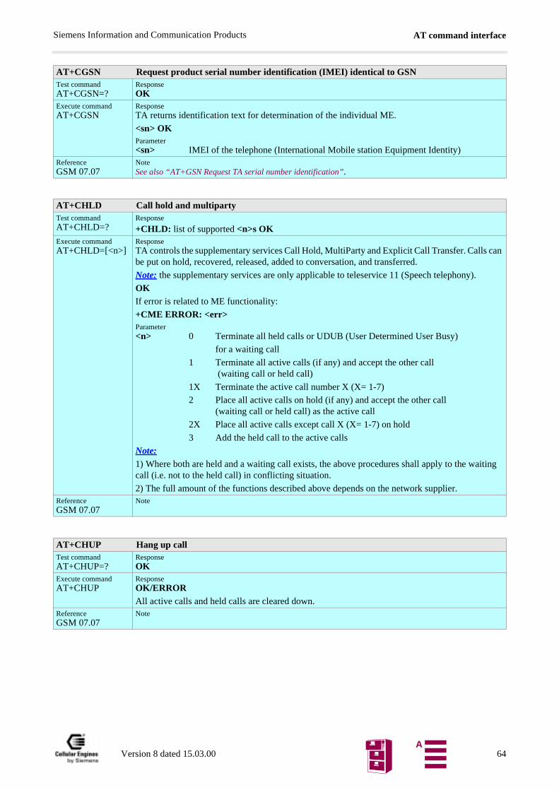
AT command interfaceSiemens Information and Communication Products
AT+CGSN Request product serial number identification (IMEI) identical to GSNTest commandAT+CGSN=?
ResponseOK
Execute commandAT+CGSN
ResponseTA returns identification text for determination of the individual ME.
<sn> OKParameter<sn> IMEI of the telephone (International Mobile station Equipment Identity)
ReferenceGSM 07.07
NoteSee also “AT+GSN Request TA serial number identification”.
AT+CHLD Call hold and multipartyTest commandAT+CHLD=?
Response
+CHLD: list of supported <n>s OKExecute commandAT+CHLD=[<n>]
ResponseTA controls the supplementary services Call Hold, MultiParty and Explicit Call Transfer. Calls can be put on hold, recovered, released, added to conversation, and transferred.
Note: the supplementary services are only applicable to teleservice 11 (Speech telephony).
OKIf error is related to ME functionality:
+CME ERROR: <err>Parameter<n> 0 Terminate all held calls or UDUB (User Determined User Busy)
for a waiting call
1 Terminate all active calls (if any) and accept the other call (waiting call or held call)
1X Terminate the active call number X (X= 1-7)
2 Place all active calls on hold (if any) and accept the other call (waiting call or held call) as the active call
2X Place all active calls except call X (X= 1-7) on hold
3 Add the held call to the active calls
Note: 1) Where both are held and a waiting call exists, the above procedures shall apply to the waiting call (i.e. not to the held call) in conflicting situation.
2) The full amount of the functions described above depends on the network supplier.ReferenceGSM 07.07
Note
AT+CHUP Hang up callTest commandAT+CHUP=?
ResponseOK
Execute commandAT+CHUP
ResponseOK/ERRORAll active calls and held calls are cleared down.
ReferenceGSM 07.07
Note
Version 8 dated 15.03.00 64A
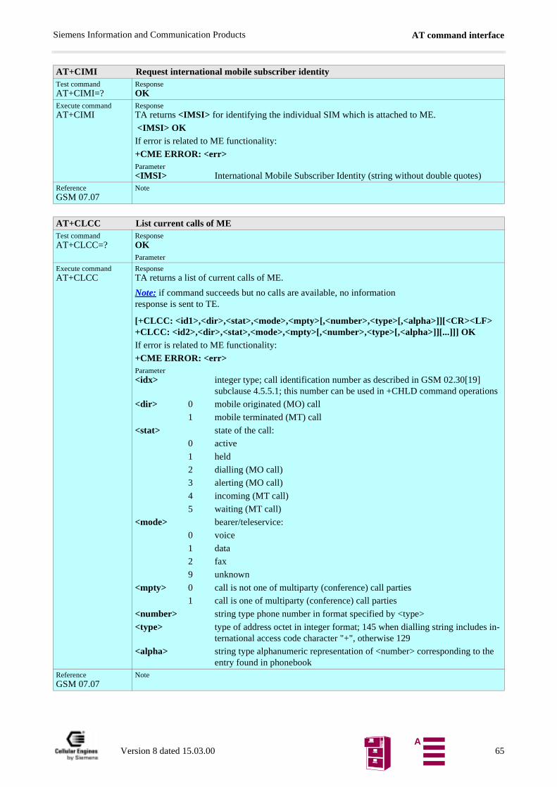
AT command interfaceSiemens Information and Communication Products
AT+CIMI Request international mobile subscriber identityTest commandAT+CIMI=?
ResponseOK
Execute commandAT+CIMI
ResponseTA returns <IMSI> for identifying the individual SIM which is attached to ME.
<IMSI> OKIf error is related to ME functionality:
+CME ERROR: <err>Parameter<IMSI> International Mobile Subscriber Identity (string without double quotes)
ReferenceGSM 07.07
Note
AT+CLCC List current calls of METest commandAT+CLCC=?
ResponseOKParameter
Execute commandAT+CLCC
ResponseTA returns a list of current calls of ME.
Note: if command succeeds but no calls are available, no information response is sent to TE.
[+CLCC: <id1>,<dir>,<stat>,<mode>,<mpty>[,<number>,<type>[,<alpha>]][<CR><LF> +CLCC: <id2>,<dir>,<stat>,<mode>,<mpty>[,<number>,<type>[,<alpha>]][...]]] OKIf error is related to ME functionality:
+CME ERROR: <err>Parameter<idx> integer type; call identification number as described in GSM 02.30[19]
subclause 4.5.5.1; this number can be used in +CHLD command operations
<dir> 0 mobile originated (MO) call
1 mobile terminated (MT) call
<stat> state of the call:
0 active
1 held
2 dialling (MO call)
3 alerting (MO call)
4 incoming (MT call)
5 waiting (MT call)
<mode> bearer/teleservice:
0 voice
1 data
2 fax
9 unknown
<mpty> 0 call is not one of multiparty (conference) call parties
1 call is one of multiparty (conference) call parties
<number> string type phone number in format specified by <type>
<type> type of address octet in integer format; 145 when dialling string includes in-ternational access code character "+", otherwise 129
<alpha> string type alphanumeric representation of <number> corresponding to the entry found in phonebook
ReferenceGSM 07.07
Note
Version 8 dated 15.03.00 65A
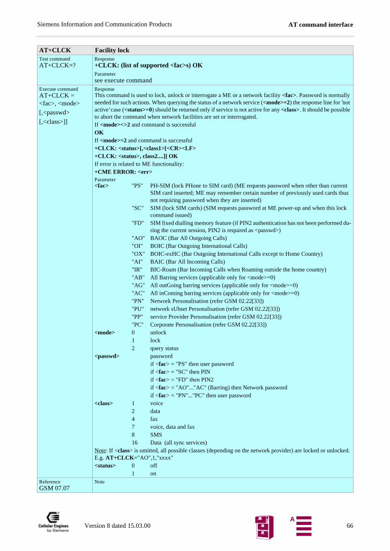
AT command interfaceSiemens Information and Communication Products
AT+CLCK Facility lockTest commandAT+CLCK=?
Response+CLCK: (list of supported <fac>s) OKParametersee execute command
Execute commandAT+CLCK = <fac>, <mode>
[,<passwd>
[,<class>]]
ResponseThis command is used to lock, unlock or interrogate a ME or a network facility <fac>. Password is normally needed for such actions. When querying the status of a network service (<mode>=2) the response line for ’not active’ case (<status>=0) should be returned only if service is not active for any <class>. It should be possible to abort the command when network facilities are set or interrogated.If <mode><>2 and command is successfulOKIf <mode>=2 and command is successful+CLCK: <status>[,<class1>[<CR><LF>+CLCK: <status>, class2....]] OKIf error is related to ME functionality:+CME ERROR: <err>Parameter<fac> "PS" PH-SIM (lock PHone to SIM card) (ME requests password when other than current
SIM card inserted; ME may remember certain number of previously used cards thus not requiring password when they are inserted)
"SC" SIM (lock SIM cards) (SIM requests password at ME power-up and when this lock command issued)
"FD" SIM fixed dialling memory feature (if PIN2 authentication has not been performed du-ring the current session, PIN2 is required as <passwd>)
"AO" BAOC (Bar All Outgoing Calls)"OI" BOIC (Bar Outgoing International Calls)"OX" BOIC-exHC (Bar Outgoing International Calls except to Home Country)"AI" BAIC (Bar All Incoming Calls)"IR" BIC-Roam (Bar Incoming Calls when Roaming outside the home country)"AB" All Barring services (applicable only for <mode>=0)"AG" All outGoing barring services (applicable only for <mode>=0)"AC" All inComing barring services (applicable only for <mode>=0)"PN" Network Personalisation (refer GSM 02.22[33])"PU" network sUbset Personalisation (refer GSM 02.22[33])"PP" service Provider Personalisation (refer GSM 02.22[33])"PC" Corporate Personalisation (refer GSM 02.22[33])
<mode> 0 unlock1 lock2 query status
<passwd> passwordif <fac> = "PS" then user passwordif <fac> = "SC" then PINif <fac> = "FD" then PIN2if <fac> = "AO"..."AC" (Barring) then Network passwordif <fac> = "PN"..."PC" then user password
<class> 1 voice2 data4 fax7 voice, data and fax 8 SMS16 Data (all sync services)
Note: If <class> is omitted, all possible classes (depending on the network provider) are locked or unlocked. E.g. AT+CLCK="AO",1,"xxxx"<status> 0 off
1 onReferenceGSM 07.07
Note
Version 8 dated 15.03.00 66A
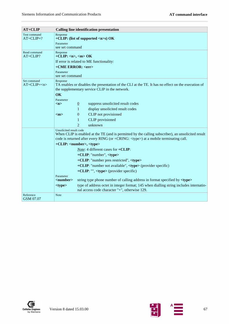
AT command interfaceSiemens Information and Communication Products
AT+CLIP Calling line identification presentationTest commandAT+CLIP=?
Response+CLIP: (list of supported <n>s) OKParametersee set command
Read commandAT+CLIP?
Response+CLIP: <n>, <m> OKIf error is related to ME functionality:
+CME ERROR: <err>Parametersee set command
Set commandAT+CLIP=<n>
ResponseTA enables or disables the presentation of the CLI at the TE. It has no effect on the execution of the supplementary service CLIP in the network.
OKParameter<n> 0 suppress unsolicited result codes
1 display unsolicited result codes
<m> 0 CLIP not provisioned
1 CLIP provisioned
2 unknownUnsolicited result codeWhen CLIP is enabled at the TE (and is permitted by the calling subscriber), an unsolicited result code is returned after every RING (or +CRING: <type>) at a mobile terminating call.
+CLIP: <number>, <type> Note: 4 different cases for +CLIP:
+CLIP: "number", <type>+CLIP: "number pres restricted", <type>+CLIP: "number not available", <type> (provider specific)
+CLIP: "", <type> (provider specific)Parameter<number> string type phone number of calling address in format specified by <type><type> type of address octet in integer format; 145 when dialling string includes internatio-
nal access code character "+", otherwise 129.ReferenceGSM 07.07
Note
Version 8 dated 15.03.00 67A
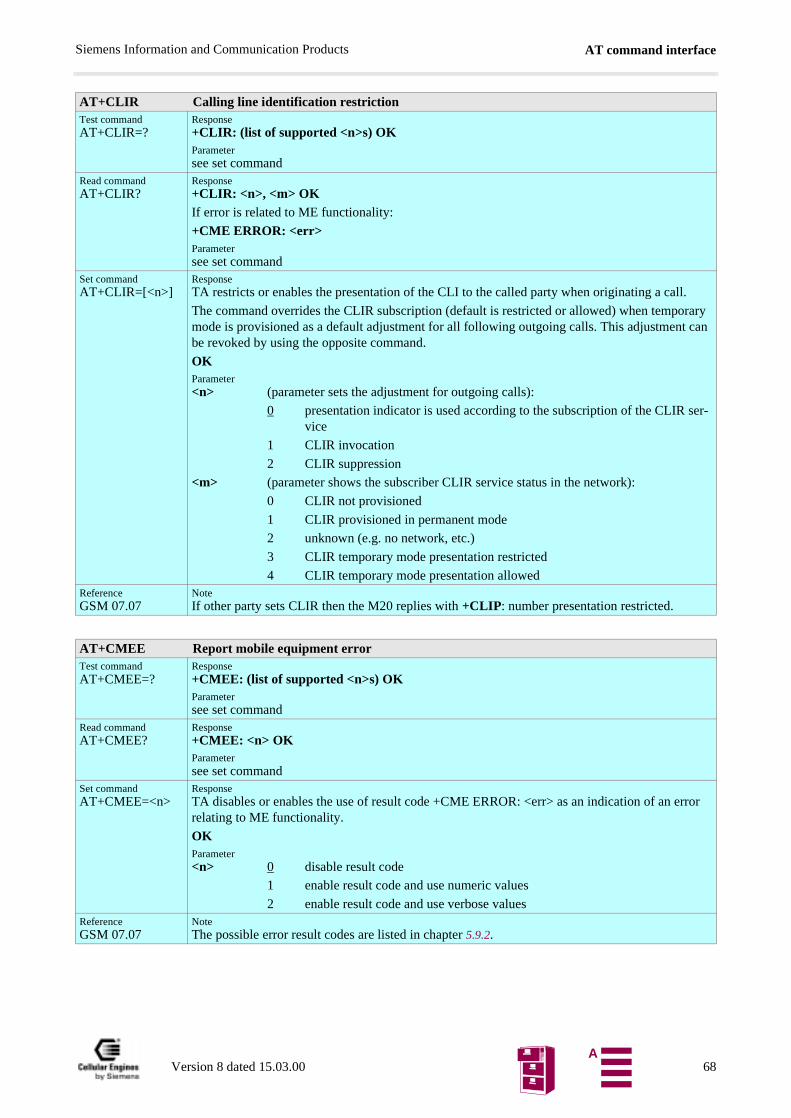
AT command interfaceSiemens Information and Communication Products
AT+CLIR Calling line identification restrictionTest commandAT+CLIR=?
Response+CLIR: (list of supported <n>s) OKParametersee set command
Read commandAT+CLIR?
Response+CLIR: <n>, <m> OKIf error is related to ME functionality:
+CME ERROR: <err>Parametersee set command
Set commandAT+CLIR=[<n>]
ResponseTA restricts or enables the presentation of the CLI to the called party when originating a call.
The command overrides the CLIR subscription (default is restricted or allowed) when temporary mode is provisioned as a default adjustment for all following outgoing calls. This adjustment can be revoked by using the opposite command.
OKParameter<n> (parameter sets the adjustment for outgoing calls):
0 presentation indicator is used according to the subscription of the CLIR ser-vice
1 CLIR invocation
2 CLIR suppression
<m> (parameter shows the subscriber CLIR service status in the network):
0 CLIR not provisioned
1 CLIR provisioned in permanent mode
2 unknown (e.g. no network, etc.)
3 CLIR temporary mode presentation restricted
4 CLIR temporary mode presentation allowedReferenceGSM 07.07
NoteIf other party sets CLIR then the M20 replies with +CLIP: number presentation restricted.
AT+CMEE Report mobile equipment errorTest commandAT+CMEE=?
Response+CMEE: (list of supported <n>s) OKParametersee set command
Read commandAT+CMEE?
Response+CMEE: <n> OKParametersee set command
Set commandAT+CMEE=<n>
ResponseTA disables or enables the use of result code +CME ERROR: <err> as an indication of an error relating to ME functionality.
OK Parameter<n> 0 disable result code
1 enable result code and use numeric values
2 enable result code and use verbose valuesReferenceGSM 07.07
NoteThe possible error result codes are listed in chapter 5.9.2.
Version 8 dated 15.03.00 68A
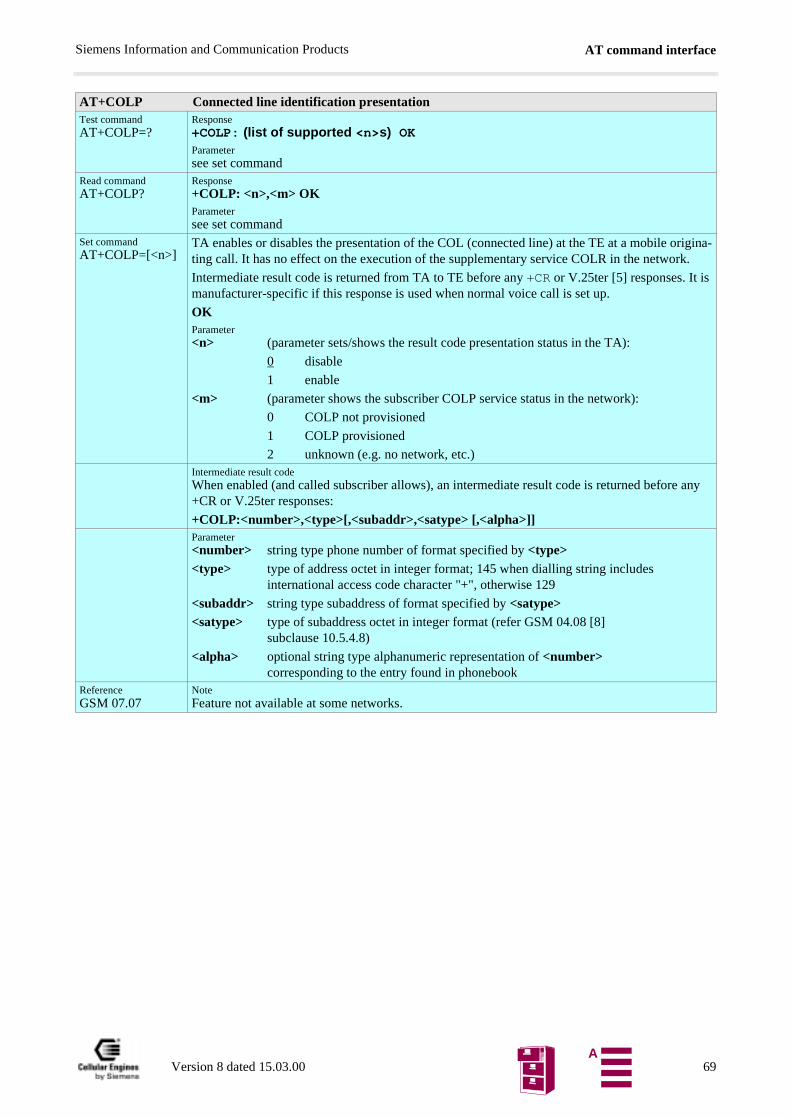
AT command interfaceSiemens Information and Communication Products
AT+COLP Connected line identification presentationTest commandAT+COLP=?
Response+COLP: (list of supported <n>s) OKParametersee set command
Read commandAT+COLP?
Response+COLP: <n>,<m> OKParametersee set command
Set commandAT+COLP=[<n>]
TA enables or disables the presentation of the COL (connected line) at the TE at a mobile origina-ting call. It has no effect on the execution of the supplementary service COLR in the network.
Intermediate result code is returned from TA to TE before any +CR or V.25ter [5] responses. It is manufacturer-specific if this response is used when normal voice call is set up.
OKParameter<n> (parameter sets/shows the result code presentation status in the TA):
0 disable
1 enable
<m> (parameter shows the subscriber COLP service status in the network):
0 COLP not provisioned
1 COLP provisioned
2 unknown (e.g. no network, etc.)Intermediate result codeWhen enabled (and called subscriber allows), an intermediate result code is returned before any +CR or V.25ter responses:
+COLP:<number>,<type>[,<subaddr>,<satype> [,<alpha>]]Parameter<number> string type phone number of format specified by <type><type> type of address octet in integer format; 145 when dialling string includes
international access code character "+", otherwise 129
<subaddr> string type subaddress of format specified by <satype><satype> type of subaddress octet in integer format (refer GSM 04.08 [8]
subclause 10.5.4.8)
<alpha> optional string type alphanumeric representation of <number> corresponding to the entry found in phonebook
ReferenceGSM 07.07
NoteFeature not available at some networks.
Version 8 dated 15.03.00 69A
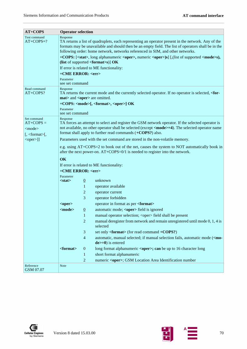
AT command interfaceSiemens Information and Communication Products
AT+COPS Operator selectionTest commandAT+COPS=?
ResponseTA returns a list of quadruplets, each representing an operator present in the network. Any of the formats may be unavailable and should then be an empty field. The list of operators shall be in the following order: home network, networks referenced in SIM, and other networks.
+COPS: [<stat>, long alphanumeric <oper>, numeric <oper>)s] [,(list of supported <mode>s), (list of supported <format>s)] OKIf error is related to ME functionality:
+CME ERROR: <err>Parametersee set command
Read commandAT+COPS?
ResponseTA returns the current mode and the currently selected operator. If no operator is selected, <for-mat> and <oper> are omitted.
+COPS: <mode>[, <format>, <oper>] OKParametersee set command
Set commandAT+COPS =
<mode>
[, <format>[, <oper>]]
ResponseTA forces an attempt to select and register the GSM network operator. If the selected operator is not available, no other operator shall be selected (except <mode>=4). The selected operator name format shall apply to further read commands (+COPS?) also.
Parameters used with the set command are stored in the non-volatile memory.
e.g. using AT+COPS=2 to book out of the net, causes the system to NOT automatically book inafter the next power-on. AT+COPS=0/1 is needed to register into the network.
OKIf error is related to ME functionality:
+CME ERROR: <err>Parameter<stat> 0 unknown
1 operator available
2 operator current
3 operator forbidden
<oper> operator in format as per <format><mode> 0 automatic mode; <oper> field is ignored
1 manual operator selection; <oper> field shall be present
2 manual deregister from network and remain unregistered until mode 0, 1, 4 is selected
3 set only <format> (for read command +COPS?)
4 automatic, manual selected; if manual selection fails, automatic mode (<mo-de>=0) is entered
<format> 0 long format alphanumeric <oper>; can be up to 16 character long
1 short format alphanumeric
2 numeric <oper>; GSM Location Area Identification numberReferenceGSM 07.07
Note
Version 8 dated 15.03.00 70A
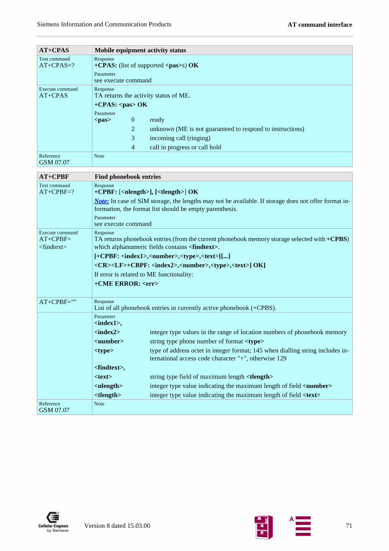
AT command interfaceSiemens Information and Communication Products
AT+CPAS Mobile equipment activity statusTest commandAT+CPAS=?
Response+CPAS: (list of supported <pas>s) OKParametersee execute command
Execute commandAT+CPAS
ResponseTA returns the activity status of ME.
+CPAS: <pas> OKParameter<pas> 0 ready
2 unknown (ME is not guaranteed to respond to instructions)
3 incoming call (ringing)
4 call in progress or call holdReferenceGSM 07.07
Note
AT+CPBF Find phonebook entriesTest commandAT+CPBF=?
Response+CPBF: [<nlength>], [<tlength>] OKNote: In case of SIM storage, the lengths may not be available. If storage does not offer format in-formation, the format list should be empty parenthesis.Parametersee execute command
Execute commandAT+CPBF=<findtext>
ResponseTA returns phonebook entries (from the current phonebook memory storage selected with +CPBS) which alphanumeric fields contains <findtext>.
[+CPBF: <index1>,<number>,<type>,<text>[[...]<CR><LF>+CBPF: <index2>,<number>,<type>,<text>] OK]If error is related to ME functionality:
+CME ERROR: <err>
AT+CPBF="" ResponseList of all phonebook entries in currently active phonebook (+CPBS).Parameter<index1>,<index2> integer type values in the range of location numbers of phonebook memory
<number> string type phone number of format <type><type> type of address octet in integer format; 145 when dialling string includes in-
ternational access code character "+", otherwise 129
<findtext>,<text> string type field of maximum length <tlength><nlength> integer type value indicating the maximum length of field <number><tlength> integer type value indicating the maximum length of field <text>
ReferenceGSM 07.07
Note
Version 8 dated 15.03.00 71A
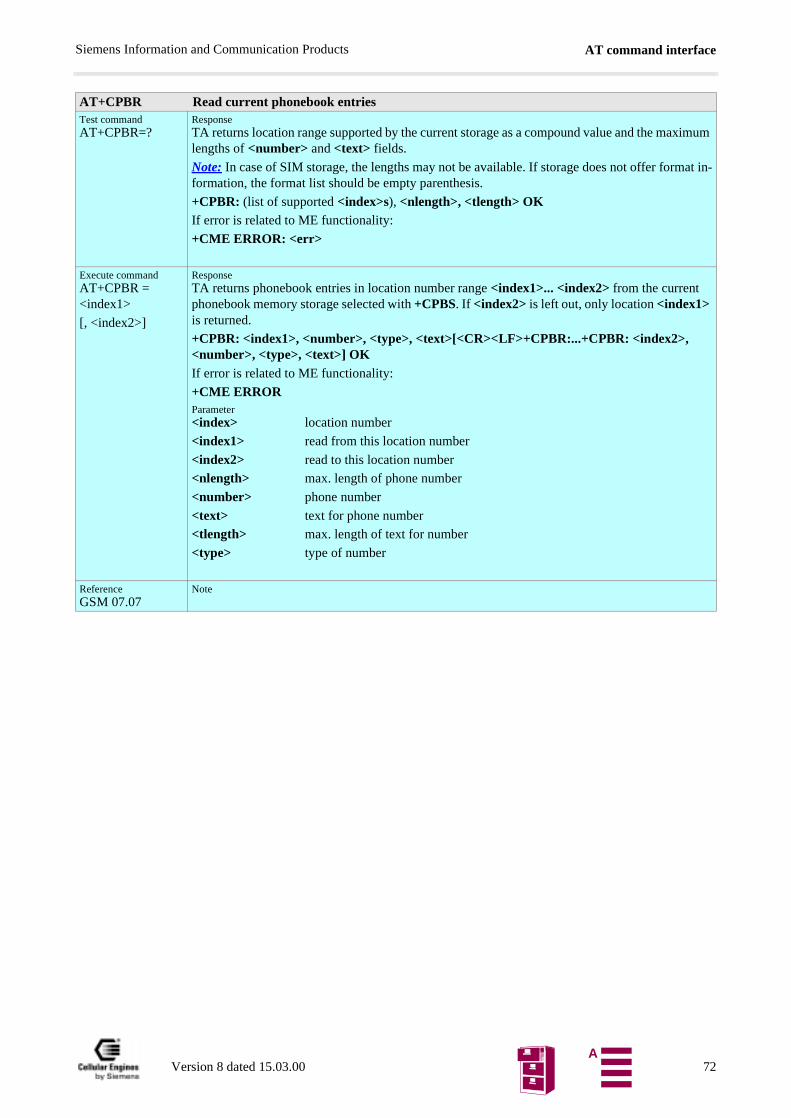
AT command interfaceSiemens Information and Communication Products
AT+CPBR Read current phonebook entriesTest commandAT+CPBR=?
ResponseTA returns location range supported by the current storage as a compound value and the maximum lengths of <number> and <text> fields.
Note: In case of SIM storage, the lengths may not be available. If storage does not offer format in-formation, the format list should be empty parenthesis.
+CPBR: (list of supported <index>s), <nlength>, <tlength> OKIf error is related to ME functionality:
+CME ERROR: <err>
Execute commandAT+CPBR = <index1>
[, <index2>]
ResponseTA returns phonebook entries in location number range <index1>... <index2> from the current phonebook memory storage selected with +CPBS. If <index2> is left out, only location <index1> is returned.
+CPBR: <index1>, <number>, <type>, <text>[<CR><LF>+CPBR:...+CPBR: <index2>, <number>, <type>, <text>] OKIf error is related to ME functionality:
+CME ERRORParameter<index> location number
<index1> read from this location number
<index2> read to this location number
<nlength> max. length of phone number
<number> phone number
<text> text for phone number
<tlength> max. length of text for number
<type> type of number
ReferenceGSM 07.07
Note
Version 8 dated 15.03.00 72A
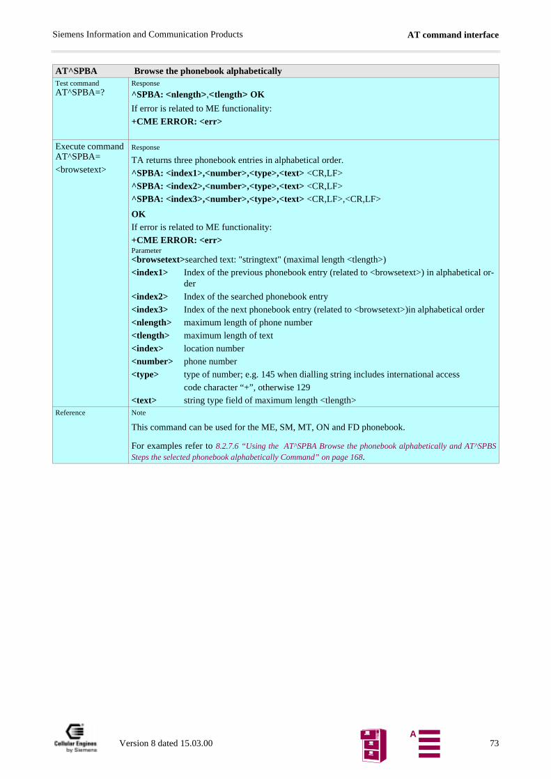
AT command interfaceSiemens Information and Communication Products
BS
AT^SPBA Browse the phonebook alphabeticallyTest commandAT^SPBA=?
Response
^SPBA: <nlength>,<tlength> OK
If error is related to ME functionality:
+CME ERROR: <err>
Execute commandAT^SPBA=
<browsetext>
Response
TA returns three phonebook entries in alphabetical order.
^SPBA: <index1>,<number>,<type>,<text> <CR,LF>
^SPBA: <index2>,<number>,<type>,<text> <CR,LF>
^SPBA: <index3>,<number>,<type>,<text> <CR,LF>,<CR,LF>
OKIf error is related to ME functionality:
+CME ERROR: <err>Parameter<browsetext>searched text: "stringtext" (maximal length <tlength>)
<index1> Index of the previous phonebook entry (related to <browsetext>) in alphabetical or-der
<index2> Index of the searched phonebook entry
<index3> Index of the next phonebook entry (related to <browsetext>)in alphabetical order
<nlength> maximum length of phone number
<tlength> maximum length of text
<index> location number
<number> phone number
<type> type of number; e.g. 145 when dialling string includes international access
code character “+”, otherwise 129
<text> string type field of maximum length <tlength>Reference Note
This command can be used for the ME, SM, MT, ON and FD phonebook.
For examples refer to 8.2.7.6 “Using the AT^SPBA Browse the phonebook alphabetically and AT^SPSteps the selected phonebook alphabetically Command” on page 168.
Version 8 dated 15.03.00 73A
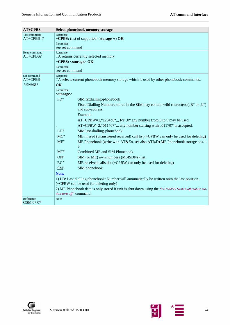
AT command interfaceSiemens Information and Communication Products
)
g)
.1-
AT+CPBS Select phonebook memory storageTest commandAT+CPBS=?
Response+CPBS: (list of supported <storage>s) OKParametersee set command
Read commandAT+CPBS?
ResponseTA returns currently selected memory
+CPBS: <storage> OKParametersee set command
Set commandAT+CPBS=<storage>
ResponseTA selects current phonebook memory storage which is used by other phonebook commands.
OKParameter<storage>"FD" SIM fixdialling-phonebook
Fixed Dialling Numbers stored in the SIM may contain wild characters („B“ or „b“and sub-address.
Example:
AT+CPBW=1,“1234b6“,,, for „b“ any number from 0 to 9 may be used
. AT+CPBW=2,“011707“,,, any number starting with „011707“is accepted.
"LD" SIM last-dialling-phonebook
"MC" ME missed (unanswered received) call list (+CPBW can only be used for deletin
"ME" ME Phonebook (write with AT&Zn, see also AT%D) ME Phonebook storage pos5
"MT" Combined ME and SIM Phonebook
"ON" SIM (or ME) own numbers (MSISDNs) list
"RC" ME received calls list (+CPBW can only be used for deleting)
"SM" SIM phonebook
Note: 1) LD: Last dialling phonebook: Number will automatically be written onto the last position. (+CPBW can be used for deleting only)
2) ME Phonebook data is only stored if unit is shut down using the “AT^SMSO Switch off mobile sta-tion turn off” command.
ReferenceGSM 07.07
Note
Version 8 dated 15.03.00 74A
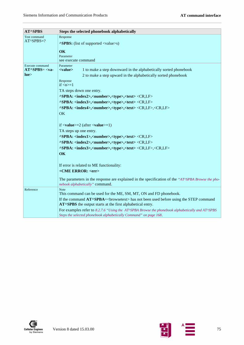
AT command interfaceSiemens Information and Communication Products
S
AT^SPBS Steps the selected phonebook alphabeticallyTest commandAT^SPBS=?
Response
^SPBS: (list of supported <value>s)
OKParametersee execute command
Execute commandAT^SPBS= <va-lue>
Parameter<value> 1 to make a step downward in the alphabetically sorted phonebook
2 to make a step upward in the alphabetically sorted phonebookResponseif <n>=1
TA steps down one entry.
^SPBA: <index2>,<number>,<type>,<text> <CR,LF>
^SPBA: <index3>,<number>,<type>,<text> <CR,LF>
^SPBA: <index4>,<number>,<type>,<text> <CR,LF>,<CR,LF>
OK
if <value>=2 (after <value>=1)
TA steps up one entry.
^SPBA: <index1>,<number>,<type>,<text> <CR,LF>
^SPBA: <index2>,<number>,<type>,<text> <CR,LF>
^SPBA: <index3>,<number>,<type>,<text> <CR,LF>,<CR,LF>
OK
If error is related to ME functionality:
+CME ERROR: <err>
The parameters in the response are explained in the specification of the “AT^SPBA Browse the pho-nebook alphabetically” command.
Reference NoteThis command can be used for the ME, SM, MT, ON and FD phonebook.
If the command AT^SPBA=<browsetext> has not been used before using the STEP command AT^SPBS the output starts at the first alphabetical entry.
For examples refer to 8.2.7.6 “Using the AT^SPBA Browse the phonebook alphabetically and AT^SPBSteps the selected phonebook alphabetically Command” on page 168.
Version 8 dated 15.03.00 75A
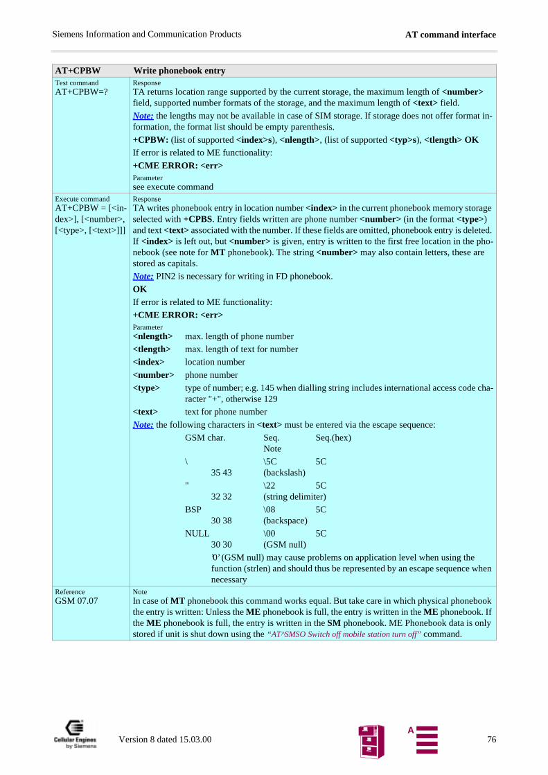
AT command interfaceSiemens Information and Communication Products
AT+CPBW Write phonebook entryTest commandAT+CPBW=?
ResponseTA returns location range supported by the current storage, the maximum length of <number> field, supported number formats of the storage, and the maximum length of <text> field.
Note: the lengths may not be available in case of SIM storage. If storage does not offer format in-formation, the format list should be empty parenthesis.
+CPBW: (list of supported <index>s), <nlength>, (list of supported <typ>s), <tlength> OKIf error is related to ME functionality:
+CME ERROR: <err>Parametersee execute command
Execute commandAT+CPBW = [<in-dex>], [<number>, [<type>, [<text>]]]
ResponseTA writes phonebook entry in location number <index> in the current phonebook memory storage selected with +CPBS. Entry fields written are phone number <number> (in the format <type>) and text <text> associated with the number. If these fields are omitted, phonebook entry is deleted. If <index> is left out, but <number> is given, entry is written to the first free location in the pho-nebook (see note for MT phonebook). The string <number> may also contain letters, these are stored as capitals.
Note: PIN2 is necessary for writing in FD phonebook.
OKIf error is related to ME functionality:
+CME ERROR: <err>Parameter<nlength> max. length of phone number
<tlength> max. length of text for number
<index> location number
<number> phone number
<type> type of number; e.g. 145 when dialling string includes international access code cha-racter "+", otherwise 129
<text> text for phone number
Note: the following characters in <text> must be entered via the escape sequence:
GSM char. Seq. Seq.(hex)Note
\ \5C 5C 35 43 (backslash)
" \22 5C 32 32 (string delimiter)
BSP \08 5C 30 38 (backspace)
NULL \00 5C 30 30 (GSM null)
’0’ (GSM null) may cause problems on application level when using the function (strlen) and should thus be represented by an escape sequence when necessary
ReferenceGSM 07.07
NoteIn case of MT phonebook this command works equal. But take care in which physical phonebook the entry is written: Unless the ME phonebook is full, the entry is written in the ME phonebook. If the ME phonebook is full, the entry is written in the SM phonebook. ME Phonebook data is only stored if unit is shut down using the “AT^SMSO Switch off mobile station turn off” command.
Version 8 dated 15.03.00 76A
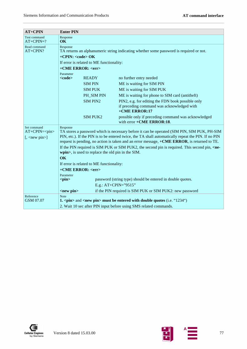
AT command interfaceSiemens Information and Communication Products
AT+CPIN Enter PINTest commandAT+CPIN=?
ResponseOK
Read commandAT+CPIN?
ResponseTA returns an alphanumeric string indicating whether some password is required or not.
+CPIN: <code> OKIf error is related to ME functionality:
+CME ERROR: <err>Parameter<code> READY no further entry needed
SIM PIN ME is waiting for SIM PIN
SIM PUK ME is waiting for SIM PUK
PH_SIM PIN ME is waiting for phone to SIM card (antitheft)
SIM PIN2 PIN2, e.g. for editing the FDN book possible only if preceding command was acknowledged with +CME ERROR:17
SIM PUK2 possible only if preceding command was acknowledgedwith error +CME ERROR:18.
Set commandAT+CPIN=<pin>
[, <new pin>]
ResponseTA stores a password which is necessary before it can be operated (SIM PIN, SIM PUK, PH-SIM PIN, etc.). If the PIN is to be entered twice, the TA shall automatically repeat the PIN. If no PIN request is pending, no action is taken and an error message, +CME ERROR, is returned to TE.
If the PIN required is SIM PUK or SIM PUK2, the second pin is required. This second pin, <ne-wpin>, is used to replace the old pin in the SIM.
OKIf error is related to ME functionality:
+CME ERROR: <err>Parameter<pin> password (string type) should be entered in double quotes.
E.g.: AT+CPIN=”9515”
<new pin> if the PIN required is SIM PUK or SIM PUK2: new passwordReferenceGSM 07.07
Note1. <pin> and <new pin> must be entered with double quotes (i.e. “1234“)
2. Wait 10 sec after PIN input before using SMS related commands.
Version 8 dated 15.03.00 77A
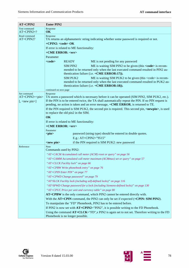
AT command interfaceSiemens Information and Communication Products
AT+CPIN2 Enter PIN2Test commandAT+CPIN2=?
ResponseOK
Read commandAT+CPIN2?
ResponseTA returns an alphanumeric string indicating whether some password is required or not.
+CPIN2: <code> OKIf error is related to ME functionality:
+CME ERROR: <err>Parameter
<code> READY ME is not pending for any password
SIM PIN2 ME is waiting SIM PIN2 to be given (this <code> is recom-mended to be returned only when the last executed command resulted in PIN2 au-thentication failure (i.e. +CME ERROR:17)).SIM PUK2 ME is waiting SIM PUK2 to be given (this <code> is recom-mended to be returned only when the last executed command resulted in PUK2 au-thentication failure (i.e. +CME ERROR:18)).
continued on next page
Set commandAT+CPIN2=<pin>
[, <new pin>]
ResponseTA stores a password which is necessary before it can be operated (SIM PIN2, SIM PUK2, etc.). If the PIN is to be entered twice, the TA shall automatically repeat the PIN. If no PIN request is pending, no action is taken and an error message, +CME ERROR, is returned to TE.
If the PIN required is SIM PUK2, the second pin is required. This second pin, <newpin>, is used to replace the old pin2 in the SIM.
OKIf error is related to ME functionality:
+CME ERROR: <err>Parameter<pin> password (string type) should be entered in double quotes.
E.g.: AT+CPIN2=”9515”
<new pin> if the PIN required is SIM PUK2: new passwordReference Note
Commands used by PIN2:
“AT+CACM Accumulated call meter (ACM) reset or query” on page 56
“AT+CAMM Accumulated call meter maximum (ACMmax) set or query” on page 57
“AT+CLCK Facility lock” on page 66
“AT+CPBW Write phonebook entry” on page 76
“AT+CPIN Enter PIN” on page 77
“AT+CPWD Change password” on page 79
“AT^SLCK Facility lock (including self-defined locks)” on page 116
“AT^SPWD Change password for a lock (including Siemens-defined locks)” on page 130
“AT+CPUC Price per unit and currency table” on page 80
AT+CPBW is the only command, which PIN2 cannot be entered directly with.
With the AT+CPIN command, the PIN2 can only be set if expected (+CPIN: SIM PIN2).
To manipulate the "FD" Phonebook, PIN2 has to be entered before.
If PIN2 is now set with AT+CPIN2="PIN2", it is possible writing to the FD Phonebook.
Using the command AT+CLCK="FD",x PIN2 is again set to not set. Therefore writing to the FD Phonebook is no longer possible.
Version 8 dated 15.03.00 78A
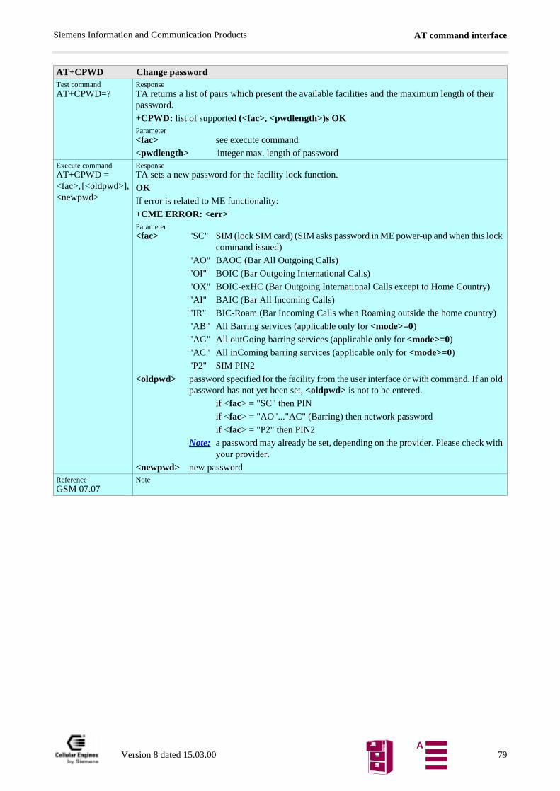
AT command interfaceSiemens Information and Communication Products
AT+CPWD Change passwordTest commandAT+CPWD=?
ResponseTA returns a list of pairs which present the available facilities and the maximum length of their password.
+CPWD: list of supported (<fac>, <pwdlength>)s OKParameter<fac> see execute command
<pwdlength> integer max. length of passwordExecute commandAT+CPWD = <fac>, [<oldpwd>], <newpwd>
ResponseTA sets a new password for the facility lock function.
OKIf error is related to ME functionality:
+CME ERROR: <err>Parameter<fac> "SC" SIM (lock SIM card) (SIM asks password in ME power-up and when this lock
command issued)
"AO" BAOC (Bar All Outgoing Calls)
"OI" BOIC (Bar Outgoing International Calls)
"OX" BOIC-exHC (Bar Outgoing International Calls except to Home Country)
"AI" BAIC (Bar All Incoming Calls)
"IR" BIC-Roam (Bar Incoming Calls when Roaming outside the home country)
"AB" All Barring services (applicable only for <mode>=0)
"AG" All outGoing barring services (applicable only for <mode>=0)
"AC" All inComing barring services (applicable only for <mode>=0)
"P2" SIM PIN2
<oldpwd> password specified for the facility from the user interface or with command. If an old password has not yet been set, <oldpwd> is not to be entered.
if <fac> = "SC" then PIN
if <fac> = "AO"..."AC" (Barring) then network password
if <fac> = "P2" then PIN2
Note: a password may already be set, depending on the provider. Please check with your provider.
<newpwd> new passwordReferenceGSM 07.07
Note
Version 8 dated 15.03.00 79A
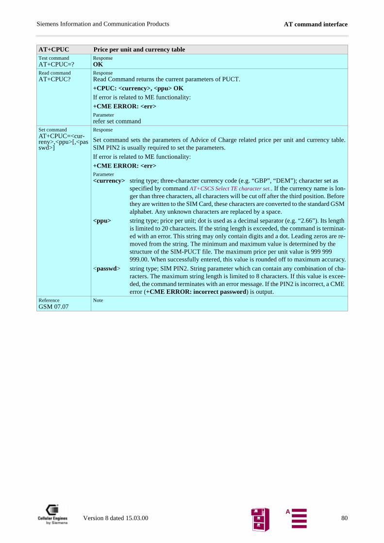
AT command interfaceSiemens Information and Communication Products
s
fore GSM
gth inat- re-
racy.
ha-ee-ME
AT+CPUC Price per unit and currency tableTest commandAT+CPUC=?
ResponseOK
Read commandAT+CPUC?
ResponseRead Command returns the current parameters of PUCT.
+CPUC: <currency>, <ppu> OKIf error is related to ME functionality:
+CME ERROR: <err>Parameterrefer set command
Set commandAT+CPUC=<cur-reny>,<ppu>[,<passwd>]
Response
Set command sets the parameters of Advice of Charge related price per unit and currency table.SIM PIN2 is usually required to set the parameters.
If error is related to ME functionality:
+CME ERROR: <err>Parameter<currency> string type; three-character currency code (e.g. “GBP”, “DEM”); character set a
specified by command AT+CSCS Select TE character set.. If the currency name is lon-ger than three characters, all characters will be cut off after the third position. Bethey are written to the SIM Card, these characters are converted to the standard alphabet. Any unknown characters are replaced by a space.
<ppu> string type; price per unit; dot is used as a decimal separator (e.g. “2.66”). Its lenis limited to 20 characters. If the string length is exceeded, the command is termed with an error. This string may only contain digits and a dot. Leading zeros aremoved from the string. The minimum and maximum value is determined by thestructure of the SIM-PUCT file. The maximum price per unit value is 999 999 999.00. When successfully entered, this value is rounded off to maximum accu
<passwd> string type; SIM PIN2. String parameter which can contain any combination of cracters. The maximum string length is limited to 8 characters. If this value is excded, the command terminates with an error message. If the PIN2 is incorrect, a Cerror (+CME ERROR: incorrect password) is output.
ReferenceGSM 07.07
Note
Version 8 dated 15.03.00 80A
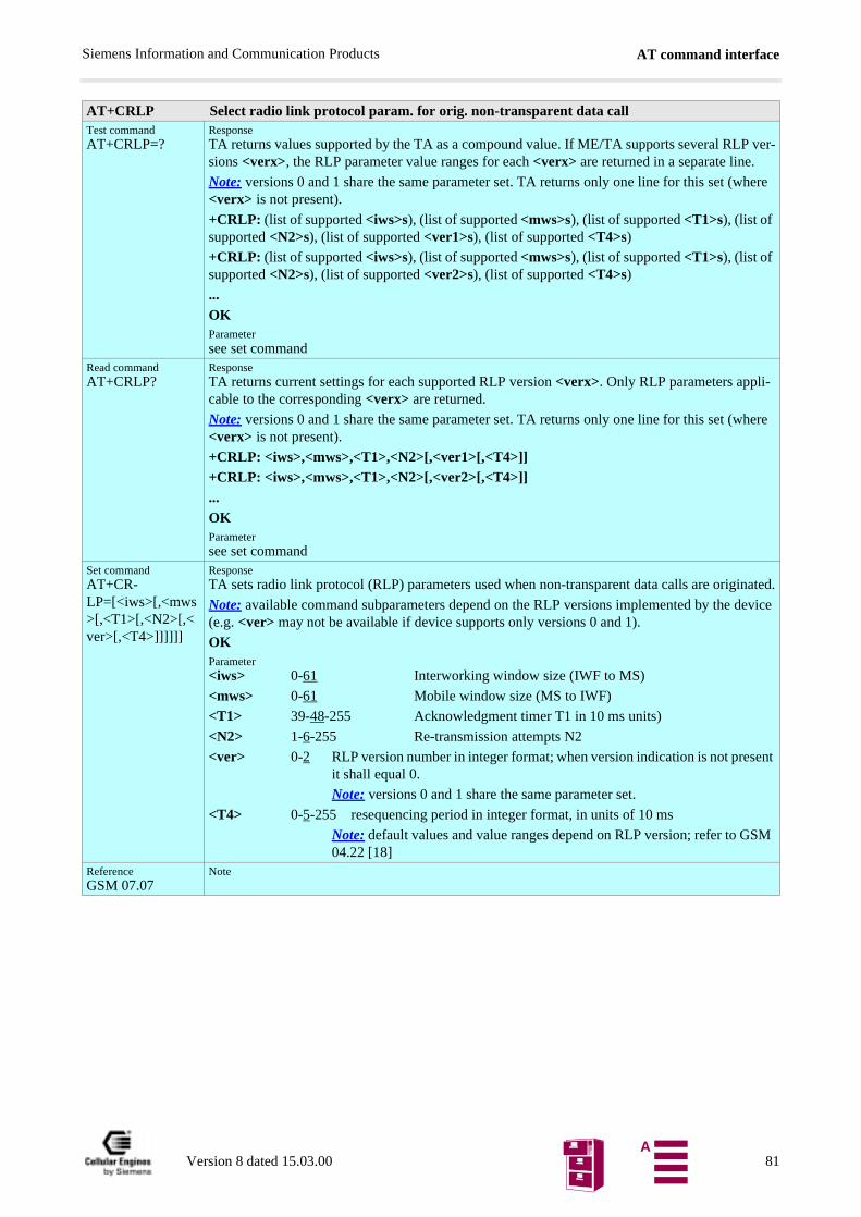
AT command interfaceSiemens Information and Communication Products
AT+CRLP Select radio link protocol param. for orig. non-transparent data callTest commandAT+CRLP=?
ResponseTA returns values supported by the TA as a compound value. If ME/TA supports several RLP ver-sions <verx>, the RLP parameter value ranges for each <verx> are returned in a separate line.
Note: versions 0 and 1 share the same parameter set. TA returns only one line for this set (where <verx> is not present).
+CRLP: (list of supported <iws>s), (list of supported <mws>s), (list of supported <T1>s), (list of supported <N2>s), (list of supported <ver1>s), (list of supported <T4>s)
+CRLP: (list of supported <iws>s), (list of supported <mws>s), (list of supported <T1>s), (list of supported <N2>s), (list of supported <ver2>s), (list of supported <T4>s)
...OKParametersee set command
Read commandAT+CRLP?
ResponseTA returns current settings for each supported RLP version <verx>. Only RLP parameters appli-cable to the corresponding <verx> are returned.
Note: versions 0 and 1 share the same parameter set. TA returns only one line for this set (where <verx> is not present).
+CRLP: <iws>,<mws>,<T1>,<N2>[,<ver1>[,<T4>]]+CRLP: <iws>,<mws>,<T1>,<N2>[,<ver2>[,<T4>]] ...OKParametersee set command
Set commandAT+CR-LP=[<iws>[,<mws>[,<T1>[,<N2>[,<ver>[,<T4>]]]]]]
ResponseTA sets radio link protocol (RLP) parameters used when non-transparent data calls are originated.
Note: available command subparameters depend on the RLP versions implemented by the device (e.g. <ver> may not be available if device supports only versions 0 and 1).
OKParameter<iws> 0-61 Interworking window size (IWF to MS)
<mws> 0-61 Mobile window size (MS to IWF)
<T1> 39-48-255 Acknowledgment timer T1 in 10 ms units)
<N2> 1-6-255 Re-transmission attempts N2
<ver> 0-2 RLP version number in integer format; when version indication is not present it shall equal 0.
Note: versions 0 and 1 share the same parameter set.
<T4> 0-5-255 resequencing period in integer format, in units of 10 ms
Note: default values and value ranges depend on RLP version; refer to GSM 04.22 [18]
ReferenceGSM 07.07
Note
Version 8 dated 15.03.00 81A
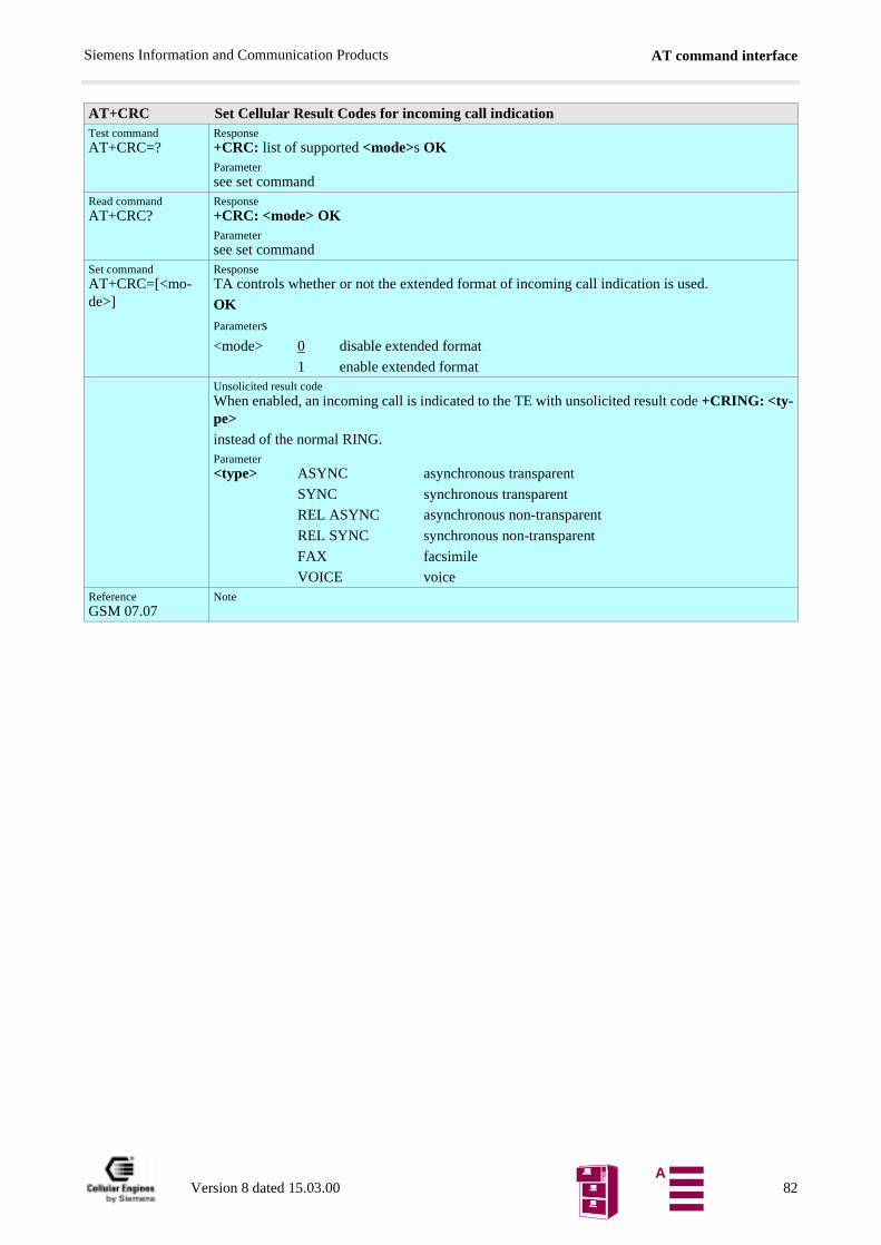
AT command interfaceSiemens Information and Communication Products
AT+CRC Set Cellular Result Codes for incoming call indicationTest commandAT+CRC=?
Response+CRC: list of supported <mode>s OKParametersee set command
Read commandAT+CRC?
Response+CRC: <mode> OKParametersee set command
Set commandAT+CRC=[<mo-de>]
ResponseTA controls whether or not the extended format of incoming call indication is used.
OKParameters
<mode> 0 disable extended format
1 enable extended formatUnsolicited result codeWhen enabled, an incoming call is indicated to the TE with unsolicited result code +CRING: <ty-pe>
instead of the normal RING.Parameter<type> ASYNC asynchronous transparent
SYNC synchronous transparent
REL ASYNC asynchronous non-transparent
REL SYNC synchronous non-transparent
FAX facsimile
VOICE voiceReferenceGSM 07.07
Note
Version 8 dated 15.03.00 82A
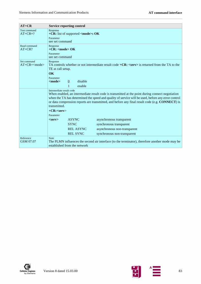
AT command interfaceSiemens Information and Communication Products
AT+CR Service reporting controlTest commandAT+CR=?
Response+CR: list of supported <mode>s OKParametersee set command
Read commandAT+CR?
Response+CR: <mode> OKParametersee set command
Set commandAT+CR=<mode>
ResponseTA controls whether or not intermediate result code +CR: <serv> is returned from the TA to the TE at call setup.
OKParameter<mode> 0 disable
1 enableIntermediate result codeWhen enabled, an intermediate result code is transmitted at the point during connect negotiation when the TA has determined the speed and quality of service will be used, before any error control or data compression reports are transmitted, and before any final result code (e.g. CONNECT) is transmitted.
+CR:<serv>Parameter
<serv> ASYNC asynchronous transparent
SYNC synchronous transparent
REL ASYNC asynchronous non-transparent
REL SYNC synchronous non-transparentReferenceGSM 07.07
NoteThe PLMN influences the second air interface (to the terminator), therefore another mode may be established from the network
Version 8 dated 15.03.00 83A
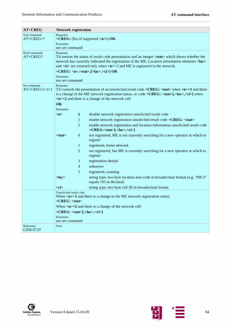
AT command interfaceSiemens Information and Communication Products
AT+CREG Network registrationTest commandAT+CREG=?
Response+CREG: (list of supported <n>s) OKParametersee set command
Read commandAT+CREG?
ResponseTA returns the status of result code presentation and an integer <stat> which shows whether the network has currently indicated the registration of the ME. Location information elements <lac> and <ci> are returned only when <n>=2 and ME is registered in the network.
+CREG: <n>,<stat>,[<lac>,<ci>] OKParametersee set command
Set commandAT+CREG=[<n>]
ResponseTA controls the presentation of an unsolicited result code +CREG: <stat> when <n>=1 and there is a change in the ME network registration status, or code +CREG: <stat>[,<lac>,<ci>] when <n>=2 and there is a change of the network cell.
OKParameter
<n> 0 disable network registration unsolicited result code
1 enable network registration unsolicited result code +CREG: <stat>2 enable network registration and location information unsolicited result code
+CREG:<stat>[,<lac>,<ci>]<stat> 0 not registered, ME is not currently searching for a new operator at which to
register
1 registered, home network
2 not registered, but ME is currently searching for a new operator at which to register
3 registration denied
4 unknown
5 registered, roaming
<lac> string type; two byte location area code in hexadecimal format (e.g. "00C3" equals 193 in decimal)
<ci> string type; two byte cell ID in hexadecimal formatUnsolicited result codeWhen <n>=1 and there is a change in the ME network registration status: +CREG: <stat>When <n>=2 and there is a change of the network cell:
+CREG: <stat>[,<lac>,<ci>]Parametersee set command
ReferenceGSM 07.07
Note
Version 8 dated 15.03.00 84A
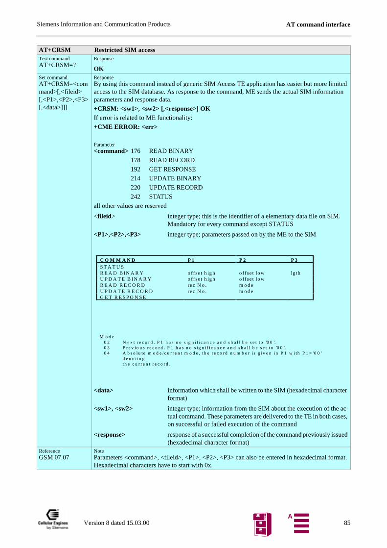
AT command interfaceSiemens Information and Communication Products
AT+CRSM Restricted SIM accessTest commandAT+CRSM=?
Response
OKSet commandAT+CRSM=<command>[,<fileid> [,<P1>,<P2>,<P3> [,<data>]]]
ResponseBy using this command instead of generic SIM Access TE application has easier but more limited access to the SIM database. As response to the command, ME sends the actual SIM information parameters and response data.
+CRSM: <sw1>, <sw2> [,<response>] OKIf error is related to ME functionality:
+CME ERROR: <err>
Parameter<command> 176 READ BINARY
178 READ RECORD
192 GET RESPONSE
214 UPDATE BINARY
220 UPDATE RECORD
242 STATUS
all other values are reserved
<fileid> integer type; this is the identifier of a elementary data file on SIM. Mandatory for every command except STATUS
<P1>,<P2>,<P3> integer type; parameters passed on by the ME to the SIM
<data> information which shall be written to the SIM (hexadecimal character format)
<sw1>, <sw2> integer type; information from the SIM about the execution of the ac-tual command. These parameters are delivered to the TE in both cases, on successful or failed execution of the command
<response> response of a successful completion of the command previously issued (hexadecimal character format)
ReferenceGSM 07.07
NoteParameters <command>, <fileid>, <P1>, <P2>, <P3> can also be entered in hexadecimal format. Hexadecimal characters have to start with 0x.
C O M M A N D P 1 P 2 P 3S T A T U SR E A D B IN A R Y o ffse t h ig h o ffse t lo w lg thU P D A T E B IN A R Y o ffse t h ig h o ffse t lo wR E A D R E C O R D re c N o . m o d eU P D A T E R E C O R D re c N o . m o d eG E T R E S P O N S E
M o d e0 2 N e x t r e c o r d . P 1 h a s n o s ig n i f i c a n c e a n d s h a l l b e s e t t o ’0 0 ’.0 3 P r e v io u s r e c o r d . P 1 h a s n o s ig n i f i c a n c e a n d s h a l l b e s e t t o ’0 0 ’.0 4 A b s o lu t e m o d e /c u r r e n t m o d e , t h e r e c o r d n u m b e r i s g iv e n in P 1 w i th P 1 = ’0 0 ’
d e n o t in gth e c u r r e n t r e c o r d .
Version 8 dated 15.03.00 85A
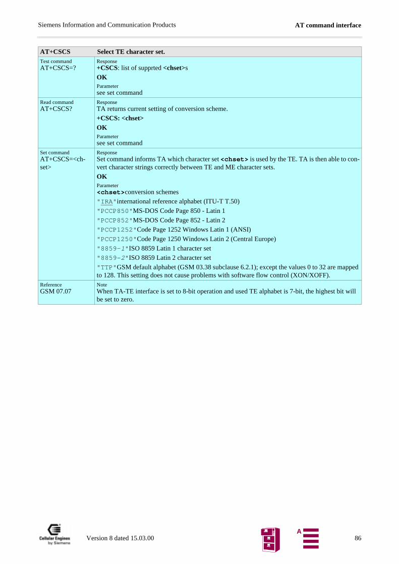
AT command interfaceSiemens Information and Communication Products
AT+CSCS Select TE character set.Test commandAT+CSCS=?
Response+CSCS: list of supprted <chset>s
OKParametersee set command
Read commandAT+CSCS?
ResponseTA returns current setting of conversion scheme.
+CSCS: <chset>
OKParametersee set command
Set commandAT+CSCS=<ch-set>
ResponseSet command informs TA which character set <chset> is used by the TE. TA is then able to con-vert character strings correctly between TE and ME character sets.
OKParameter<chset>conversion schemes
"IRA"international reference alphabet (ITU-T T.50)
"PCCP850"MS-DOS Code Page 850 - Latin 1
"PCCP852"MS-DOS Code Page 852 - Latin 2
"PCCP1252"Code Page 1252 Windows Latin 1 (ANSI)
"PCCP1250"Code Page 1250 Windows Latin 2 (Central Europe)
"8859-1"ISO 8859 Latin 1 character set
"8859-2"ISO 8859 Latin 2 character set
"TTP"GSM default alphabet (GSM 03.38 subclause 6.2.1); except the values 0 to 32 are mapped to 128. This setting does not cause problems with software flow control (XON/XOFF).
ReferenceGSM 07.07
NoteWhen TA-TE interface is set to 8-bit operation and used TE alphabet is 7-bit, the highest bit will be set to zero.
Version 8 dated 15.03.00 86A
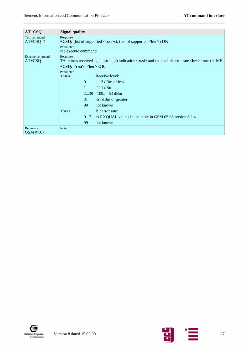
AT command interfaceSiemens Information and Communication Products
AT+CSQ Signal qualityTest commandAT+CSQ=?
Response+CSQ: (list of supported <rssi>s), (list of supported <ber>) OKParametersee execute command
Execute commandAT+CSQ
ResponseTA returns received signal strength indication <rssi> and channel bit error rate <ber> from the ME.
+CSQ: <rssi>, <ber> OKParameter<rssi> Receive level:
0 -113 dBm or less
1 -111 dBm
2...30 -109... -53 dBm
31 -51 dBm or greater
99 not known
<ber> Bit error rate:
0...7 as RXQUAL values in the table in GSM 05.08 section 8.2.4
99 not knownReferenceGSM 07.07
Note
Version 8 dated 15.03.00 87A
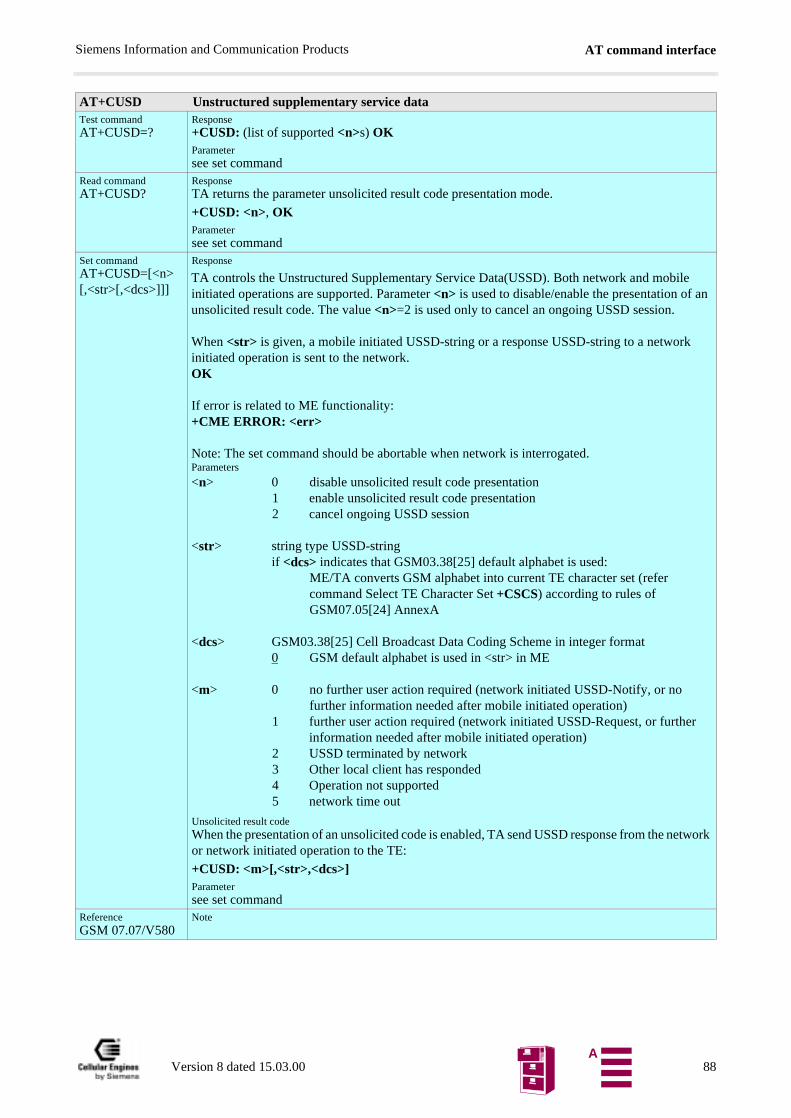
AT command interfaceSiemens Information and Communication Products
AT+CUSD Unstructured supplementary service dataTest commandAT+CUSD=?
Response+CUSD: (list of supported <n>s) OKParametersee set command
Read commandAT+CUSD?
ResponseTA returns the parameter unsolicited result code presentation mode.
+CUSD: <n>, OKParametersee set command
Set commandAT+CUSD=[<n> [,<str>[,<dcs>]]]
Response
Unsolicited result codeWhen the presentation of an unsolicited code is enabled, TA send USSD response from the network or network initiated operation to the TE:
+CUSD: <m>[,<str>,<dcs>]Parametersee set command
ReferenceGSM 07.07/V580
Note
TA controls the Unstructured Supplementary Service Data(USSD). Both network and mobileinitiated operations are supported. Parameter <n> is used to disable/enable the presentation of anunsolicited result code. The value <n>=2 is used only to cancel an ongoing USSD session.
When <str> is given, a mobile initiated USSD-string or a response USSD-string to a networkinitiated operation is sent to the network.OK
If error is related to ME functionality:+CME ERROR: <err>
Note: The set command should be abortable when network is interrogated.Parameters
<n> 0 disable unsolicited result code presentation1 enable unsolicited result code presentation2 cancel ongoing USSD session
<str> string type USSD-stringif <dcs> indicates that GSM03.38[25] default alphabet is used:
ME/TA converts GSM alphabet into current TE character set (refercommand Select TE Character Set +CSCS) according to rules ofGSM07.05[24] AnnexA
<dcs> GSM03.38[25] Cell Broadcast Data Coding Scheme in integer format0 GSM default alphabet is used in <str> in ME
<m> 0 no further user action required (network initiated USSD-Notify, or nofurther information needed after mobile initiated operation)
1 further user action required (network initiated USSD-Request, or furtherinformation needed after mobile initiated operation)
2 USSD terminated by network3 Other local client has responded4 Operation not supported5 network time out
Version 8 dated 15.03.00 88A
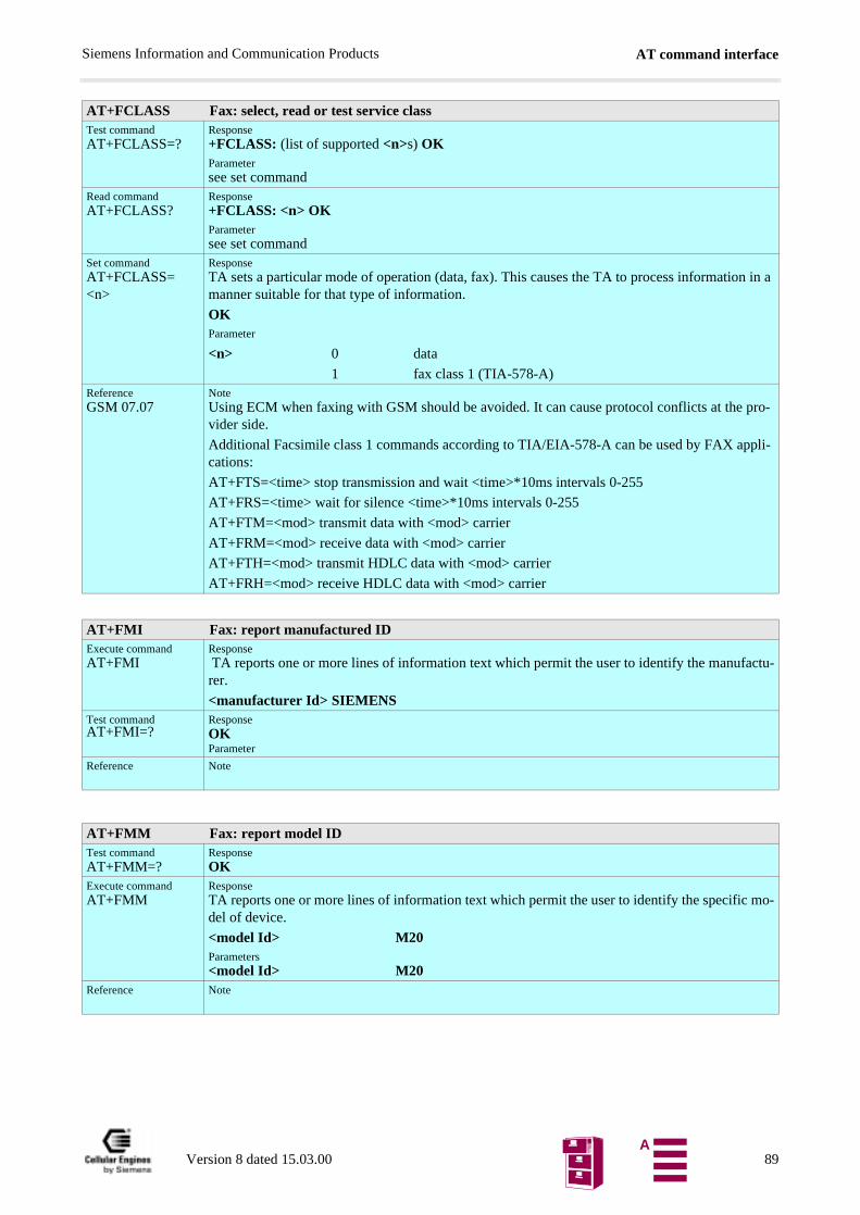
AT command interfaceSiemens Information and Communication Products
AT+FCLASS Fax: select, read or test service classTest commandAT+FCLASS=?
Response+FCLASS: (list of supported <n>s) OKParametersee set command
Read commandAT+FCLASS?
Response+FCLASS: <n> OKParametersee set command
Set commandAT+FCLASS=<n>
ResponseTA sets a particular mode of operation (data, fax). This causes the TA to process information in a manner suitable for that type of information.
OKParameter
<n> 0 data
1 fax class 1 (TIA-578-A)ReferenceGSM 07.07
NoteUsing ECM when faxing with GSM should be avoided. It can cause protocol conflicts at the pro-vider side.
Additional Facsimile class 1 commands according to TIA/EIA-578-A can be used by FAX appli-cations:
AT+FTS=<time> stop transmission and wait <time>*10ms intervals 0-255
AT+FRS=<time> wait for silence <time>*10ms intervals 0-255
AT+FTM=<mod> transmit data with <mod> carrier
AT+FRM=<mod> receive data with <mod> carrier
AT+FTH=<mod> transmit HDLC data with <mod> carrier
AT+FRH=<mod> receive HDLC data with <mod> carrier
AT+FMI Fax: report manufactured IDExecute commandAT+FMI
Response TA reports one or more lines of information text which permit the user to identify the manufactu-rer.
<manufacturer Id> SIEMENSTest commandAT+FMI=?
ResponseOKParameter
Reference Note
AT+FMM Fax: report model IDTest commandAT+FMM=?
ResponseOK
Execute commandAT+FMM
ResponseTA reports one or more lines of information text which permit the user to identify the specific mo-del of device.
<model Id> M20Parameters<model Id> M20
Reference Note
Version 8 dated 15.03.00 89A
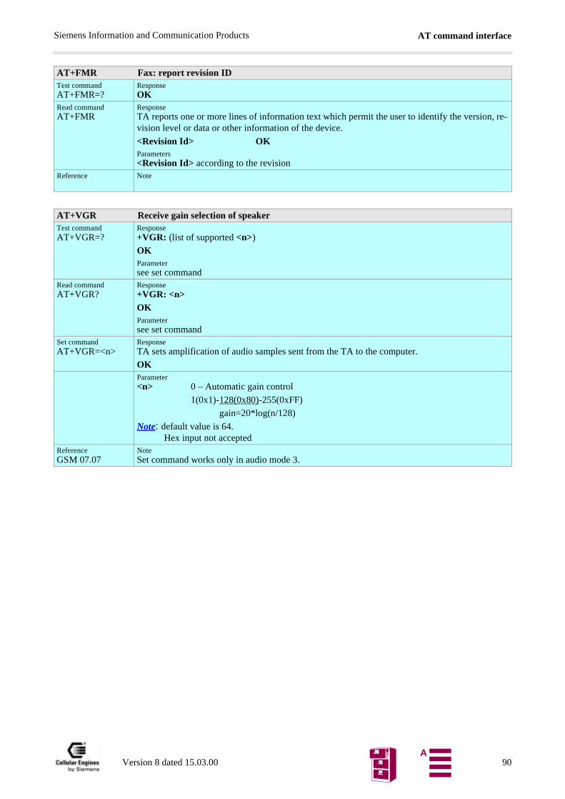
AT command interfaceSiemens Information and Communication Products
AT+FMR Fax: report revision IDTest commandAT+FMR=?
ResponseOK
Read commandAT+FMR
ResponseTA reports one or more lines of information text which permit the user to identify the version, re-vision level or data or other information of the device.
<Revision Id> OKParameters<Revision Id> according to the revision
Reference Note
AT+VGR Receive gain selection of speakerTest commandAT+VGR=?
Response+VGR: (list of supported <n>)
OKParametersee set command
Read commandAT+VGR?
Response+VGR: <n>OKParametersee set command
Set commandAT+VGR=<n>
ResponseTA sets amplification of audio samples sent from the TA to the computer.
OKParameter<n> 0 – Automatic gain control
1(0x1)-128(0x80)-255(0xFF)
gain=20*log(n/128)
Note: default value is 64.Hex input not accepted
ReferenceGSM 07.07
NoteSet command works only in audio mode 3.
Version 8 dated 15.03.00 90A
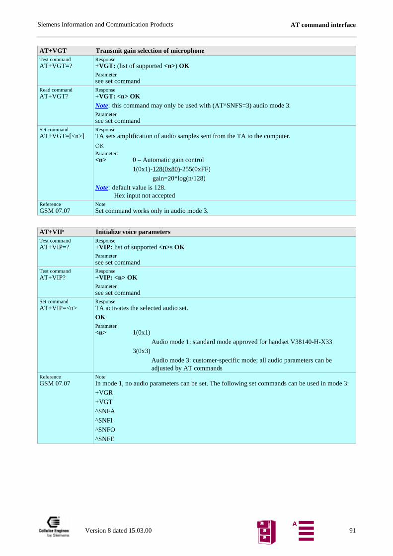
AT command interfaceSiemens Information and Communication Products
de 3:
AT+VGT Transmit gain selection of microphoneTest commandAT+VGT=?
Response+VGT: (list of supported <n>) OKParametersee set command
Read commandAT+VGT?
Response+VGT: <n> OKNote: this command may only be used with (AT^SNFS=3) audio mode 3.Parametersee set command
Set commandAT+VGT=[<n>]
ResponseTA sets amplification of audio samples sent from the TA to the computer.
OKParameter:<n> 0 – Automatic gain control
1(0x1)-128(0x80)-255(0xFF)
gain=20*log(n/128)
Note: default value is 128.Hex input not accepted
ReferenceGSM 07.07
NoteSet command works only in audio mode 3.
AT+VIP Initialize voice parametersTest commandAT+VIP=?
Response+VIP: list of supported <n>s OKParametersee set command
Test commandAT+VIP?
Response+VIP: <n> OKParametersee set command
Set commandAT+VIP=<n>
ResponseTA activates the selected audio set.
OKParameter<n> 1(0x1)
Audio mode 1: standard mode approved for handset V38140-H-X33
3(0x3)
Audio mode 3: customer-specific mode; all audio parameters can beadjusted by AT commands
ReferenceGSM 07.07
NoteIn mode 1, no audio parameters can be set. The following set commands can be used in mo
+VGR
+VGT
^SNFA
^SNFI
^SNFO
^SNFE
Version 8 dated 15.03.00 91A
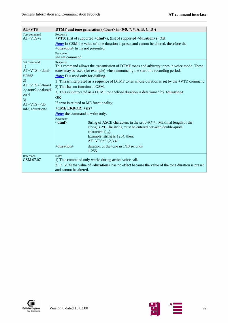
AT command interfaceSiemens Information and Communication Products
set
AT+VTS DTMF and tone generation (<Tone> in 0-9, *, #, A, B, C, D)Test commandAT+VTS=?
Response+VTS: (list of supported <dtmf>s, (list of supported <duration>s) OKNote: In GSM the value of tone duration is preset and cannot be altered. therefore the <duration> list is not presented.Parametersee set command
Set command1) AT+VTS=<dtmf-string>
2) AT+VTS=[<tone1>,<tone2>,<durati-on>]
3) AT+VTS=<dt-mf>,<duration>
ResponseThis command allows the transmission of DTMF tones and arbitrary tones in voice mode. These tones may be used (for example) when announcing the start of a recording period.
Note: D is used only for dialling.
1) This is interpreted as a sequence of DTMF tones whose duration is set by the +VTD command.
2) This has no function at GSM.
3) This is interpreted as a DTMF tone whose duration is determined by <duration>.
OKIf error is related to ME functionality:
+CME ERROR: <err>Note: the command is write only.Parameter<dtmf> String of ASCII characters in the set 0-9,#,*,. Maximal length of the
string is 29. The string must be entered between double-quote characters („„).Example: string is 1234, then:AT+VTS="1,2,3,4"
<duration> duration of the tone in 1/10 seconds1-255
ReferenceGSM 07.07
Note:1) This command only works during active voice call.
2) In GSM the value of <duration> has no effect because the value of the tone duration is preand cannot be altered.
Version 8 dated 15.03.00 92A
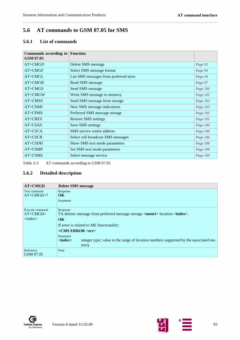
AT command interfaceSiemens Information and Communication Products
5.6 AT commands to GSM 07.05 for SMS
5.6.1 List of commands
Table 5-3 AT commands according to GSM 07.05
5.6.2 Detailed description
Commands according toGSM 07.05
Function
AT+CMGD Delete SMS message Page 93
AT+CMGF Select SMS message format Page 94
AT+CMGL List SMS messages from preferred store Page 94
AT+CMGR Read SMS message Page 97
AT+CMGS Send SMS message Page 100
AT+CMGW Write SMS message to memory Page 101
AT+CMSS Send SMS message from storage Page 102
AT+CNMI New SMS message indications Page 103
AT+CPMS Preferred SMS message storage Page 105
AT+CRES Restore SMS settings Page 105
AT+CSAS Save SMS settings Page 106
AT+CSCA SMS service centre address Page 106
AT+CSCB Select cell broadcast SMS messages Page 106
AT+CSDH Show SMS text mode parameters Page 108
AT+CSMP Set SMS text mode parameters Page 109
AT+CSMS Select message service Page 109
AT+CMGD Delete SMS messageTest commandAT+CMGD=?
ResponseOKParameter
Execute commandAT+CMGD=<index>
ResponseTA deletes message from preferred message storage <mem1> location <index>.
OKIf error is related to ME functionality:
+CMS ERROR <err>Parameter<index> integer type; value in the range of location numbers supported by the associated me-
moryReferenceGSM 07.05
Note
Version 8 dated 15.03.00 93A
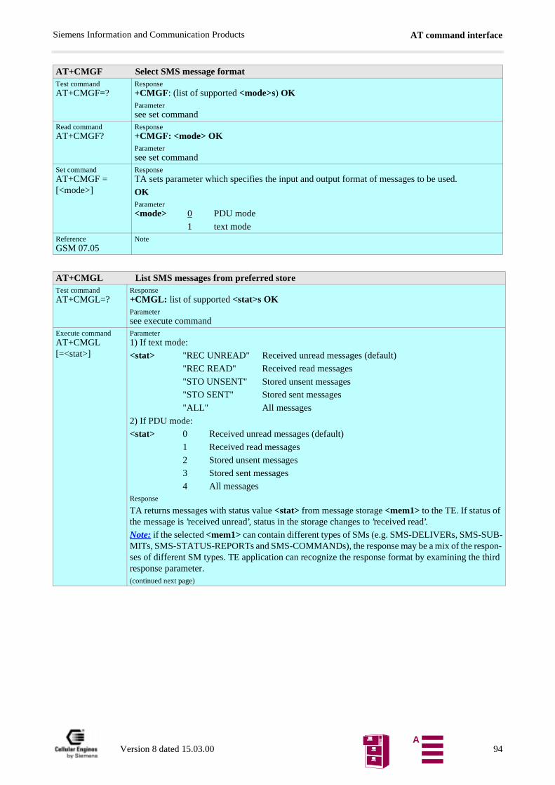
AT command interfaceSiemens Information and Communication Products
AT+CMGF Select SMS message formatTest commandAT+CMGF=?
Response+CMGF: (list of supported <mode>s) OKParametersee set command
Read commandAT+CMGF?
Response+CMGF: <mode> OKParametersee set command
Set commandAT+CMGF = [<mode>]
ResponseTA sets parameter which specifies the input and output format of messages to be used.
OKParameter<mode> 0 PDU mode
1 text modeReferenceGSM 07.05
Note
AT+CMGL List SMS messages from preferred storeTest commandAT+CMGL=?
Response+CMGL: list of supported <stat>s OKParametersee execute command
Execute commandAT+CMGL [=<stat>]
Parameter1) If text mode:
<stat> "REC UNREAD" Received unread messages (default)
"REC READ" Received read messages
"STO UNSENT" Stored unsent messages
"STO SENT" Stored sent messages
"ALL" All messages
2) If PDU mode:
<stat> 0 Received unread messages (default)
1 Received read messages
2 Stored unsent messages
3 Stored sent messages
4 All messagesResponse
TA returns messages with status value <stat> from message storage <mem1> to the TE. If status of the message is ’received unread’, status in the storage changes to ’received read’.
Note: if the selected <mem1> can contain different types of SMs (e.g. SMS-DELIVERs, SMS-SUB-MITs, SMS-STATUS-REPORTs and SMS-COMMANDs), the response may be a mix of the respon-ses of different SM types. TE application can recognize the response format by examining the third response parameter.(continued next page)
Version 8 dated 15.03.00 94A
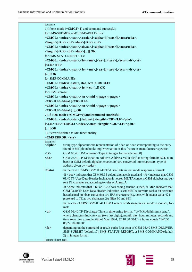
AT command interfaceSiemens Information and Communication Products
s and /
ER, lt
Response
1) If text mode (+CMGF=1) and command successful:
for SMS-SUBMITs and/or SMS-DELIVERs:
+CMGL: <index>,<stat>,<oa/da>,[<alpha>],[<scts>][,<tooa/toda>,<length>]<CR><LF><data>[<CR><LF>+CMGL: <index>,<stat>,<da/oa>,[<alpha>],[<scts>][,<tooa/toda>,<length>]<CR><LF><data>[...]] OKfor SMS-STATUS-REPORTs:
+CMGL: <index>,<stat>,<fo>,<mr>,[<ra>],[<tora>],<scts>,<dt>,<st>[<CR><LF>+CMGL: <index>,<stat>,<fo>,<mr>,[<ra>],[<tora>],<scts>,<dt>,<st>[...]] OKfor SMS-COMMANDs:
+CMGL: <index>,<stat>,<fo>,<ct>[<CR><LF>+CMGL: <index>,<stat>,<fo>,<ct>[...]] OKfor CBM storage:
+CMGL: <index>,<stat>,<sn>,<mid>,<page>,<pages><CR><LF><data>[<CR><LF>+CMGL: <index>,<stat>,<sn>,<mid>,<page>,<pages><CR><LF><data>[...]]OK2) If PDU mode (+CMGF=0) and command successful:+CMGL: <index>,<stat>,[<alpha>],<length><CR><LF><pdu>[<CR><LF>+CMGL: <index>,<stat>,<length><CR><LF><pdu>[...]] OK3) If error is related to ME functionality:
+CMS ERROR: <err>Parameter<alpha> string type alphanumeric representation of <da> or <oa> corresponding to the entry
found in MT phonebook; implementation of this feature is manufacturer-specific
<ct> GSM 03.40 TP-Command-Type in integer format (default 0)
<da> GSM 03.40 TP-Destination-Address Address-Value field in string format; BCD num-bers (or GSM default alphabet characters) are converted into characters; type of address given by <toda>
<data> In the case of SMS: GSM 03.40 TP-User-Data in text mode responses; format:
-if <dcs> indicates that GSM 03.38 default alphabet is used and <fo> indicates that GSM 03.40 TP-User-Data-Header-Indication is not set: ME/TA converts GSM alphabet into cur-rent TE character set according to rules of Annex A
-if <dcs> indicates that 8-bit or UCS2 data coding scheme is used, or <fo> indicates that GSM 03.40 TP-User-Data-Header-Indication is set: ME/TA converts each 8-bit octet into hexadecimal numbers containing two IRA characters (e.g. octet with integer value 42 is presented to TE as two characters 2A (IRA 50 and 65))
In the case of CBS: GSM 03.41 CBM Content of Message in text mode responses; for-mat:
<dt> GSM 03.40 TP-Discharge-Time in time-string format: "yy/MM/dd,hh:mm:ss±zz", where characters indicate year (two last digits), month, day, hour, minutes, secondtime zone. For example, 6th of May 1994, 22:10:00 GMT+2 hours equals "94/0506,22:10:00+08"
<fo> depending on the command or result code: first octet of GSM 03.40 SMS-DELIVSMS-SUBMIT (default 17), SMS-STATUS-REPORT, or SMS-COMMAND (defau2) in integer format
(continued next page)
Version 8 dated 15.03.00 95A
AT command interfaceSiemens Information and Communication Products
Parameter<length> integer type value indicating in the text mode (+CMGF=1) the length of the message
body <data> (or <cdata>) in characters; or in PDU mode (+CMGF=0), the length of the actual TP data unit in octets (i.e. the RP layer SMSC address octets are not counted in the length)
<index> integer type; value in the range of location numbers supported by the associated me-mory
<mid> GSM 03.41 CBM Message Identifier in integer format
<mr> GSM 03.40 TP-Message-Reference in integer format
<oa> GSM 03.40 TP-Originating-Address Address-Value field in string format; BCD num-bers (or GSM default alphabet characters) are converted into characters; type of address given by <tooa>
<pages> GSM 03.41 CBM Page Parameter bits 0-3 in integer format
<pdu> In the case of SMS: GSM 04.11 SC address followed by GSM 03.40 TPDU in hexade-cimal format: ME/TA converts each octet of TP data unit into hexadecimal numbers containing two IRA characters (e.g. octet with integer value 42 is presented to TE as two characters 2A (IRA 50 and 65)). In the case of CBS: GSM 03.41 TPDU in hexade-cimal format.
<page> GSM 03.41 CBM Page Parameter bits 4-7 in integer format
<ra> GSM 03.40 TP-Recipient-Address Address-Value field in string format; BCD num-bers (or GSM default alphabet characters) are converted into characters; type of address given by <tora>
<scts> GSM 03.40 TP-Service-Centre-Time-Stamp in time-string format (refer <dt>)
<sn> GSM 03.41 CBM Serial Number in integer format
<st> GSM 03.40 TP-Status in integer format
<toda> GSM 04.11 TP-Destination-Address Type-of-Address octet in integer format (when first character of <da> is + (IRA 43) default is 145, otherwise default is 129)
<tooa> GSM 04.11 TP-Originating-Address Type-of-Address octet in integer format (default refer<toda>)
<tora> GSM 04.11 TP-Recipient-Address Type-of-Address octet in integer format (default re-fer<toda>)
ReferenceGSM 07.05
Note
Version 8 dated 15.03.00 96A
AT command interfaceSiemens Information and Communication Products
AT+CMGR Read SMS messageTest commandAT+CMGR=?
ResponseOKParameter
Execute commandAT+CMGR=<index>
Parameter<index> integer type; value in the range of location numbers supported by the associated me-
moryResponseTA returns SMS message with location value <index> from message storage <mem1> to the TE. If status of the message is ’received unread’, status in the storage changes to ’received read’.
1) If text mode (+CMGF=1) and command successful:
for SMS-DELIVER:
+CMGR: <stat>,<oa>,[<alpha>],<scts> [,<tooa>,<fo>,<pid>,<dcs>,<sca>,<tosca>,<length>]<CR><LF><data>for SMS-SUBMIT:
+CMGR: <stat>,<da>,[<alpha>] [,<toda>,<fo>,<pid>,<dcs>,[<vp>],<sca>,<tosca>,<length>]<CR><LF><data>for SMS-STATUS-REPORT:
+CMGR: <stat>,<fo>,<mr>,[<ra>],[<tora>],<scts>,<dt>,<st>for SMS-COMMAND:
+CMGR: <stat>,<fo>,<ct> [,<pid>,[<mn>],[<da>],[<toda>],<length><CR><LF><cdata>]for CBM storage:
+CMGR: <stat>,<sn>,<mid>,<dcs>,<page>,<pages><CR><LF><data>2) If PDU mode (+CMGF=0) and command successful:+CMGR: <stat>,[<alpha>],<length><CR><LF><pdu> OK3) If error is related to ME functionality:
+CMS ERROR: <err>Parameter<stat> integer type in PDU mode (default 0), or string type in text mode (default "REC UN-
READ"); indicates the status of message in memory; defined values:
0 "REC UNREAD" received unread message (i.e. new message)
1 "REC READ" received read message
2 "STO UNSENT" stored unsent message (only applicable to SMs)
3 "STO SENT" stored sent message (only applicable to SMs)
4 "ALL" all messages (only applicable to AT+CMGL List SMS messages from preferred store command)
<alpha> string type alphanumeric representation of <da> or <oa> corresponding to the entry found in MT phonebook; implementation of this feature is manufacturer-specific
<ct> GSM 03.40 TP-Command-Type in integer format (default 0)
<da> GSM 03.40 TP-Destination-Address Address-Value field in string format; BCD numbers (or GSM default alphabet characters) are converted into characters; type of address given by <toda>
<data> In the case of SMS: GSM 03.40 TP-User-Data in text mode responses; format:(continued next page)
Version 8 dated 15.03.00 97A
AT command interfaceSiemens Information and Communication Products
, nds
94/
R,
coun-
me-
pe of
e- nted
M n by
Parameter
-if <dcs> indicates that GSM 03.38 default alphabet is used and <fo> indicates that GSM 03.40 TP-User-Data-Header-Indication is not set: ME/TA converts GSM alphabet into cur-rent TE character set according to rules covered in Annex A
-if <dcs> indicates that 8-bit or UCS2 data coding scheme is used, or <fo> indicates that GSM 03.40 TP-User-Data-Header-Indication is set: ME/TA converts each 8-bit octet into hexadecimal numbers containing two IRA characters (e.g. octet with integer value 42 is presented to TE as two characters 2A (IRA 50 and 65))
In the case of CBS: GSM 03.41 CBM Content of Message in text mode responses; format:
- if <dcs> indicates that GSM 03.38 default alphabet is used:
ME/TA converts GSM alphabet into current TE character set according to rules co-vered in Annex A
-if <dcs> indicates that 8-bit or UCS2 data coding scheme is used: ME/TA converts each 8-bit octet into hexadecimal numbers containing two IRA characters
<dcs> depending on the command or result code: GSM 03.38 SMS Data Coding Scheme (default 0), or Cell Broadcast Data Coding Scheme in integer format
<cdata> GSM 03.40 TP-Command-Data in text mode responses; ME/TA converts each 8-bit octet into two IRA character long hexadecimal number (e.g. octet with integer value 42 is presented to TE as two characters 2A (IRA 50 and 65))
<dt> GSM 03.40 TP-Discharge-Time in time-string format: “yy/MM/dd,hh:mm:ss±zz”where characters indicate year (two last digits), month, day, hour, minutes, secoand time zone. For example, 6th of May 1994, 22:10:00 GMT+2 hours equals “05/06,22:10:00+08”
<fo> depending on the command or result code: first octet of GSM 03.40 SMS-DELIVESMS-SUBMIT (default 17), SMS-STATUS-REPORT, or SMS-COMMAND (de-fault 2) in integer format
<length> integer type value indicating in text mode (+CMGF=1) the length of the message body <data> (or <cdata>) in characters; or in PDU mode (+CMGF=0), the length of the actual TP data unit in octets (i.e. the RP layer SMSC address octets are notted in the length)
<index> integer type; value in the range of location numbers supported by the associatedmory
<mid> GSM 03.41 CBM Message Identifier in integer format
<mr> GSM 03.40 TP-Message-Reference in integer format
<oa> GSM 03.40 TP-Originating-Address Address-Value field in string format; BCD numbers (or GSM default alphabet characters) are converted into characters; tyaddress given by <tooa>
<page> GSM 03.41 CBM Page Parameter bits 4-7 in integer format
<pages> GSM 03.41 CBM Page Parameter bits 0-3 in integer format
<pdu> In the case of SMS: GSM 04.11 SC address followed by GSM 03.40 TPDU in hxadecimal format: ME/TA converts each octet of TP data unit into hexadecimalnumbers containing two IRA characters (e.g. octet with integer value 42 is preseto TE as two characters 2A (IRA 50 and 65)). In the case of CBS: <ra> GSM 03.40 TP-Recipient-Address Address-Value field in string format; BCD numbers (or GSdefault alphabet characters) are converted into characters; type of address give<tora>
(continued next page)
Version 8 dated 15.03.00 98A
AT command interfaceSiemens Information and Communication Products
<pid> GSM 03.40 TP-Protocol-Identifier in integer format (default 0)
<ra> GSM 03.40 TP-Recipient-Address Address-Value field in string format; BCD num-bers (or GSM default alphabet characters) are converted to characters of the currently selected TE character set (refer command AT+CSCS Select TE character set.); type of address given by <tora>
<sca> GSM 04.11 RP SC address Address-Value field in string format; BCD numbers (or GSM default alphabet characters) are converted to characters of the currently selec-ted TE character set (refer command AT+CSCS Select TE character set.); type of address given by <tosca>
<scts> GSM 03.40 TP-Service-Centre-Time-Stamp in time-string format (refer <dt>)
<sn> GSM 03.41 CBM Serial Number in integer format
<st> GSM 03.40 TP-Status in integer format
<toda> GSM 04.11 TP-Destination-Address Type-of-Address octet in integer format (when first character of <da> is + (IRA 43) default is 145, otherwise default is 129)
<tooa> GSM 04.11 TP-Originating-Address Type-of-Address octet in integer format (de-fault refer<toda>)
<tora> GSM 04.11 TP-Recipient-Address Type-of-Address octet in integer format (default refer<toda>)
<tosca> GSM 04.11 RP SC address Type-of-Address octet in integer format (default refer <toda>)
<vp> depending on SMS-SUBMIT <fo> setting: GSM 03.40 TP-Validity-Period either in integer format (default 167) or in time-string format (refer <dt>)
ReferenceGSM 07.05
Note
Version 8 dated 15.03.00 99A
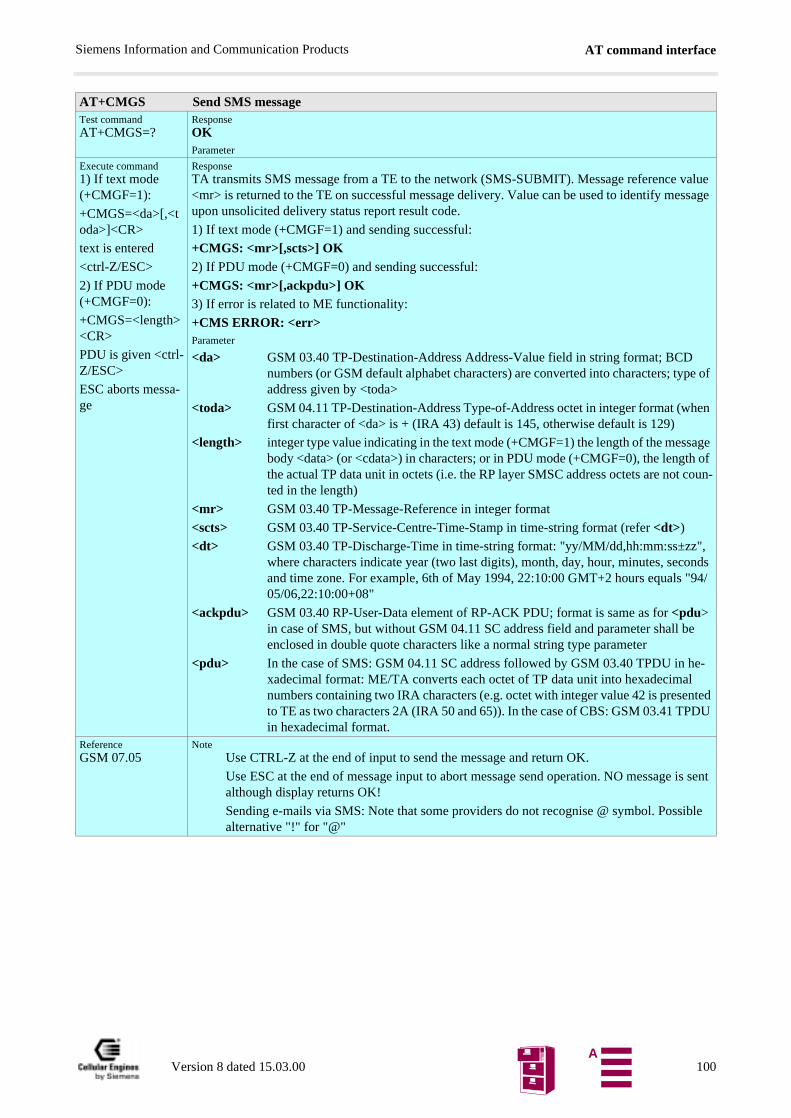
AT command interfaceSiemens Information and Communication Products
, nds
94/
e
e- nted DU
is sent
ible
AT+CMGS Send SMS messageTest commandAT+CMGS=?
ResponseOKParameter
Execute command1) If text mode (+CMGF=1):
+CMGS=<da>[,<toda>]<CR>
text is entered
<ctrl-Z/ESC>
2) If PDU mode (+CMGF=0):
+CMGS=<length><CR>
PDU is given <ctrl-Z/ESC>
ESC aborts messa-ge
ResponseTA transmits SMS message from a TE to the network (SMS-SUBMIT). Message reference value <mr> is returned to the TE on successful message delivery. Value can be used to identify message upon unsolicited delivery status report result code.
1) If text mode (+CMGF=1) and sending successful:
+CMGS: <mr>[,scts>] OK2) If PDU mode (+CMGF=0) and sending successful:
+CMGS: <mr>[,ackpdu>] OK3) If error is related to ME functionality:
+CMS ERROR: <err>Parameter
<da> GSM 03.40 TP-Destination-Address Address-Value field in string format; BCD numbers (or GSM default alphabet characters) are converted into characters; type of address given by <toda>
<toda> GSM 04.11 TP-Destination-Address Type-of-Address octet in integer format (when first character of <da> is + (IRA 43) default is 145, otherwise default is 129)
<length> integer type value indicating in the text mode (+CMGF=1) the length of the message body <data> (or <cdata>) in characters; or in PDU mode (+CMGF=0), the length of the actual TP data unit in octets (i.e. the RP layer SMSC address octets are not coun-ted in the length)
<mr> GSM 03.40 TP-Message-Reference in integer format
<scts> GSM 03.40 TP-Service-Centre-Time-Stamp in time-string format (refer <dt>)
<dt> GSM 03.40 TP-Discharge-Time in time-string format: "yy/MM/dd,hh:mm:ss±zz"where characters indicate year (two last digits), month, day, hour, minutes, secoand time zone. For example, 6th of May 1994, 22:10:00 GMT+2 hours equals "05/06,22:10:00+08"
<ackpdu> GSM 03.40 RP-User-Data element of RP-ACK PDU; format is same as for <pdu> in case of SMS, but without GSM 04.11 SC address field and parameter shall benclosed in double quote characters like a normal string type parameter
<pdu> In the case of SMS: GSM 04.11 SC address followed by GSM 03.40 TPDU in hxadecimal format: ME/TA converts each octet of TP data unit into hexadecimalnumbers containing two IRA characters (e.g. octet with integer value 42 is preseto TE as two characters 2A (IRA 50 and 65)). In the case of CBS: GSM 03.41 TPin hexadecimal format.
ReferenceGSM 07.05
NoteUse CTRL-Z at the end of input to send the message and return OK.
Use ESC at the end of message input to abort message send operation. NO messagealthough display returns OK!
Sending e-mails via SMS: Note that some providers do not recognise @ symbol. Possalternative "!" for "@"
Version 8 dated 15.03.00 100A
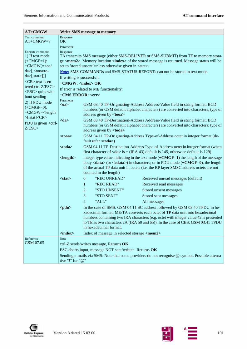
AT command interfaceSiemens Information and Communication Products
AT+CMGW Write SMS message to memoryTest commandAT+CMGW=?
ResponseOKParameter
Execute command1) If text mode (+CMGF=1):+CMGW[=<oa/da>[,<tooa/to-da>[,stat>]]]
<CR> text is en-tered ctrl-Z/ESC><ESC> quits wit-hout sending
2) If PDU mode (+CMGF=0):+CMGW=<length>[,stat]<CR>
PDU is given <ctrl-Z/ESC>
ResponseTA transmits SMS message (either SMS-DELIVER or SMS-SUBMIT) from TE to memory stora-ge <mem2>. Memory location <index> of the stored message is returned. Message status will be set to ’stored unsent’ unless otherwise given in <stat>.
Note: SMS-COMMANDs and SMS-STATUS-REPORTs can not be stored in text mode.
If writing is successful:
+CMGW: <index> OKIf error is related to ME functionality:
+CMS ERROR: <err>Parameter<oa> GSM 03.40 TP-Originating-Address Address-Value field in string format; BCD
numbers (or GSM default alphabet characters) are converted into characters; type of address given by <tooa>
<da> GSM 03.40 TP-Destination-Address Address-Value field in string format; BCD numbers (or GSM default alphabet characters) are converted into characters; type of address given by <toda>
<tooa> GSM 04.11 TP-Originating-Address Type-of-Address octet in integer format (de-fault refer <toda>)
<toda> GSM 04.11 TP-Destination-Address Type-of-Address octet in integer format (when first character of <da> is + (IRA 43) default is 145, otherwise default is 129)
<length> integer type value indicating in the text mode (+CMGF=1) the length of the message body <data> (or <cdata>) in characters; or in PDU mode (+CMGF=0), the length of the actual TP data unit in octets (i.e. the RP layer SMSC address octets are not counted in the length)
<stat> 0 "REC UNREAD" Received unread messages (default)
1 "REC READ" Received read messages
2 "STO UNSENT" Stored unsent messages
3 "STO SENT" Stored sent messages
4 "ALL" All messages
<pdu> In the case of SMS: GSM 04.11 SC address followed by GSM 03.40 TPDU in he-xadecimal format: ME/TA converts each octet of TP data unit into hexadecimal numbers containing two IRA characters (e.g. octet with integer value 42 is presented to TE as two characters 2A (IRA 50 and 65)). In the case of CBS: GSM 03.41 TPDU in hexadecimal format.
<index> Index of message in selected storage <mem2>ReferenceGSM 07.05
Note
ctrl-Z sends/writes message, Returns OKESC aborts input, message NOT sent/written. Returns OKSending e-mails via SMS: Note that some providers do not recognise @ symbol. Possible alterna-tive "!" for "@"
Version 8 dated 15.03.00 101A
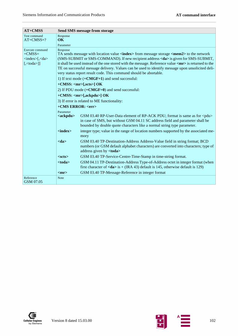
AT command interfaceSiemens Information and Communication Products
AT+CMSS Send SMS message from storageTest commandAT+CMSS=?
ResponseOKParameter
Execute command+CMSS=<index>[,<da>[,<toda>]]
ResponseTA sends message with location value <index> from message storage <mem2> to the network (SMS-SUBMIT or SMS-COMMAND). If new recipient address <da> is given for SMS-SUBMIT, it shall be used instead of the one stored with the message. Reference value <mr> is returned to the TE on successful message delivery. Values can be used to identify message upon unsolicited deli-very status report result code. This command should be abortable.
1) If text mode (+CMGF=1) and send successful:
+CMSS: <mr>[,scts>] OK2) If PDU mode (+CMGF=0) and send successful:
+CMSS: <mr>[,ackpdu>] OK3) If error is related to ME functionality:
+CMS ERROR: <err>Parameter<ackpdu> GSM 03.40 RP-User-Data element of RP-ACK PDU; format is same as for <pdu>
in case of SMS, but without GSM 04.11 SC address field and parameter shall be bounded by double quote characters like a normal string type parameter.
<index> integer type; value in the range of location numbers supported by the associated me-mory
<da> GSM 03.40 TP-Destination-Address Address-Value field in string format; BCD numbers (or GSM default alphabet characters) are converted into characters; type of address given by <toda>
<scts> GSM 03.40 TP-Service-Centre-Time-Stamp in time-string format.
<toda> GSM 04.11 TP-Destination-Address Type-of-Address octet in integer format (when first character of <da> is + (IRA 43) default is 145, otherwise default is 129)
<mr> GSM 03.40 TP-Message-Reference in integer formatReferenceGSM 07.05
Note
Version 8 dated 15.03.00 102A
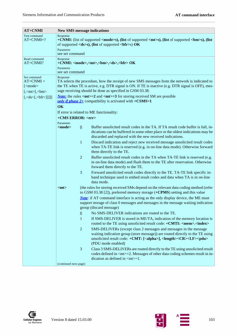
AT command interfaceSiemens Information and Communication Products
AT+CNMI New SMS message indicationsTest commandAT+CNMI=?
Response+CNMI: (list of supported <mode>s), (list of supported <mt>s), (list of supported <bm>s), (list of supported <ds>s), (list of supported <bfr>s) OKParametersee set command
Read commandAT+CNMI?
Response+CNMI: <mode>,<mt>,<bm>,<ds>,<bfr> OKParametersee set command
Set commandAT+CNMI = [<mode>
[,<mt>[,<bm>
[,<ds>[,<bfr>]]]]]
ResponseTA selects the procedure, how the receipt of new SMS messages from the network is indicated to the TE when TE is active, e.g. DTR signal is ON. If TE is inactive (e.g. DTR signal is OFF), mes-sage receiving should be done as specified in GSM 03.38.
Note: the rules <mt>=2 and <mt>=3 for storing received SM are possible only if phase 2+ compatibility is activated with +CSMS=1OKIf error is related to ME functionality:
+CMS ERROR: <err>Parameter<mode> 0 Buffer unsolicited result codes in the TA. If TA result code buffer is full, in-
dications can be buffered in some other place or the oldest indications may be discarded and replaced with the new received indications.
1 Discard indication and reject new received message unsolicited result codes when TA-TE link is reserved (e.g. in on-line data mode). Otherwise forward them directly to the TE.
2 Buffer unsolicited result codes in the TA when TA-TE link is reserved (e.g. in on-line data mode) and flush them to the TE after reservation. Otherwise forward them directly to the TE.
3 Forward unsolicited result codes directly to the TE. TA-TE link specific in-band technique used to embed result codes and data when TA is in on-line data mode.
<mt> (the rules for storing received SMs depend on the relevant data coding method (refer to GSM 03.38 [2]), preferred memory storage (+CPMS) setting and this value
Note: if AT command interface is acting as the only display device, the ME must support storage of class 0 messages and messages in the message waiting indication group (discard message)
0 No SMS-DELIVER indications are routed to the TE.
1 If SMS-DELIVER is stored in ME/TA, indication of the memory location is routed to the TE using unsolicited result code: +CMTI: <mem>,<index>
2 SMS-DELIVERs (except class 2 messages and messages in the message waiting indication group (store message)) are routed directly to the TE using unsolicited result code: +CMT: [<alpha>], <length><CR><LF><pdu> (PDU mode enabled)
3 Class 3 SMS-DELIVERs are routed directly to the TE using unsolicited result codes defined in <mt>=2. Messages of other data coding schemes result in in-dication as defined in <mt>=1.
(continued next page)
Version 8 dated 15.03.00 103A
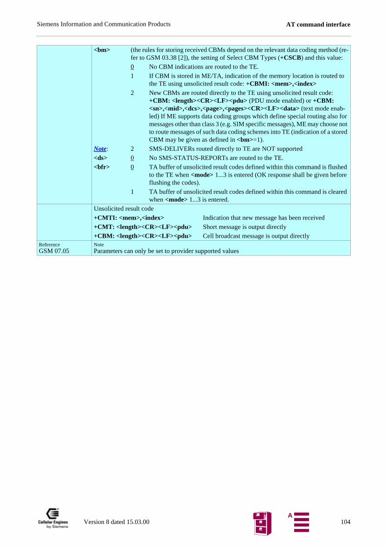
AT command interfaceSiemens Information and Communication Products
<bm> (the rules for storing received CBMs depend on the relevant data coding method (re-fer to GSM 03.38 [2]), the setting of Select CBM Types (+CSCB) and this value:
0 No CBM indications are routed to the TE.
1 If CBM is stored in ME/TA, indication of the memory location is routed to the TE using unsolicited result code: +CBMI: <mem>,<index>
2 New CBMs are routed directly to the TE using unsolicited result code: +CBM: <length><CR><LF><pdu> (PDU mode enabled) or +CBM: <sn>,<mid>,<dcs>,<page>,<pages><CR><LF><data> (text mode enab-led) If ME supports data coding groups which define special routing also for messages other than class 3 (e.g. SIM specific messages), ME may choose not to route messages of such data coding schemes into TE (indication of a stored CBM may be given as defined in <bm>=1).
Note: 2 SMS-DELIVERs routed directly to TE are NOT supported
<ds> 0 No SMS-STATUS-REPORTs are routed to the TE.
<bfr> 0 TA buffer of unsolicited result codes defined within this command is flushed to the TE when <mode> 1...3 is entered (OK response shall be given before flushing the codes).
1 TA buffer of unsolicited result codes defined within this command is cleared when <mode> 1...3 is entered.
Unsolicited result code
+CMTI: <mem>,<index> Indication that new message has been received
+CMT: <length><CR><LF><pdu> Short message is output directly
+CBM: <length><CR><LF><pdu> Cell broadcast message is output directlyReferenceGSM 07.05
NoteParameters can only be set to provider supported values
Version 8 dated 15.03.00 104A
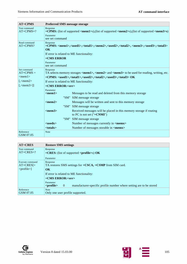
AT command interfaceSiemens Information and Communication Products
AT+CPMS Preferred SMS message storageTest commandAT+CPMS=?
Response+CPMS: (list of supported <mem1>s),(list of supported <mem2>s),(list of supported <mem3>s)Parametersee set command
Read commandAT+CPMS?
Response+CPMS: <mem1>,<used1>,<total1>,<mem2>,<used2>,<total2>, <mem3>,<used3>,<total3> OKIf error is related to ME functionality:
+CMS ERRORParametersee set command
Set commandAT+CPMS = <mem1>
[,<mem2>
[,<mem3>]]
ResponseTA selects memory storages <mem1>, <mem2> and <mem3> to be used for reading, writing, etc.
+CPMS: <used1>,<total1>,<used2>,<total2>,<used3>,<total3> OKIf error is related to ME functionality:
+CMS ERROR:<err>Parameter<mem1> Messages to be read and deleted from this memory storage
"SM" SIM message storage
<mem2> Messages will be written and sent to this memory storage
"SM" SIM message storage
<mem3> Received messages will be placed in this memory storage if routingto PC is not set ("+CNMI")
"SM" SIM message storage
<usedx> Number of messages currently in <memx><totalx> Number of messages storable in <memx>
ReferenceGSM 07.05
Note
AT+CRES Restore SMS settingsTest commandAT+CRES=?
Response
+CRES: (list of supported <profile>s) OK
Parameter
Execute commandAT+CRES[=<profile>]
ResponseTA restores SMS settings for +CSCA, +CSMP from SIM card.
OKIf error is related to ME functionality:
+CMS ERROR:<err>Parameter<profile> 0 manufacturer-specific profile number where setting are to be stored
ReferenceGSM 07.05
NoteOnly one user profile supported.
Version 8 dated 15.03.00 105A
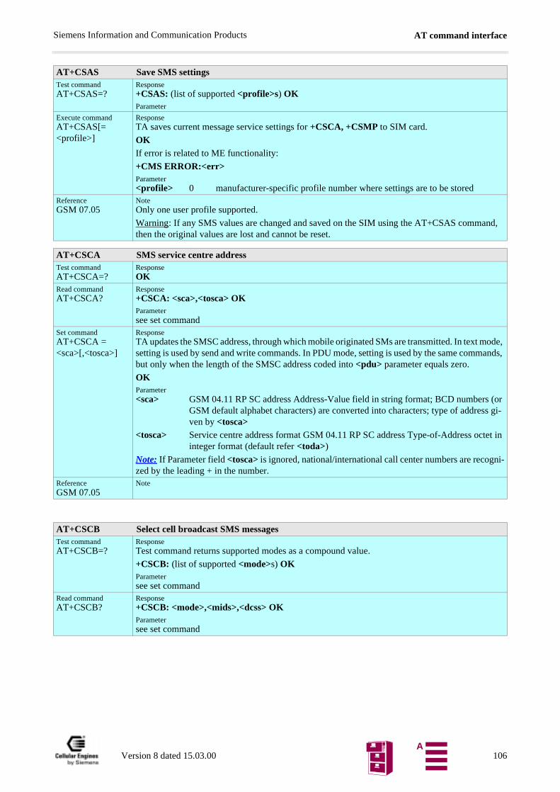
AT command interfaceSiemens Information and Communication Products
AT+CSAS Save SMS settingsTest commandAT+CSAS=?
Response+CSAS: (list of supported <profile>s) OKParameter
Execute commandAT+CSAS[=<profile>]
ResponseTA saves current message service settings for +CSCA, +CSMP to SIM card.
OKIf error is related to ME functionality:
+CMS ERROR:<err>Parameter<profile> 0 manufacturer-specific profile number where settings are to be stored
ReferenceGSM 07.05
NoteOnly one user profile supported.
Warning: If any SMS values are changed and saved on the SIM using the AT+CSAS command, then the original values are lost and cannot be reset.
AT+CSCA SMS service centre addressTest commandAT+CSCA=?
ResponseOK
Read commandAT+CSCA?
Response+CSCA: <sca>,<tosca> OKParametersee set command
Set commandAT+CSCA = <sca>[,<tosca>]
ResponseTA updates the SMSC address, through which mobile originated SMs are transmitted. In text mode, setting is used by send and write commands. In PDU mode, setting is used by the same commands, but only when the length of the SMSC address coded into <pdu> parameter equals zero.
OKParameter<sca> GSM 04.11 RP SC address Address-Value field in string format; BCD numbers (or
GSM default alphabet characters) are converted into characters; type of address gi-ven by <tosca>
<tosca> Service centre address format GSM 04.11 RP SC address Type-of-Address octet in integer format (default refer <toda>)
Note: If Parameter field <tosca> is ignored, national/international call center numbers are recogni-zed by the leading + in the number.
ReferenceGSM 07.05
Note
AT+CSCB Select cell broadcast SMS messagesTest commandAT+CSCB=?
ResponseTest command returns supported modes as a compound value.
+CSCB: (list of supported <mode>s) OKParametersee set command
Read commandAT+CSCB?
Response+CSCB: <mode>,<mids>,<dcss> OKParametersee set command
Version 8 dated 15.03.00 106A
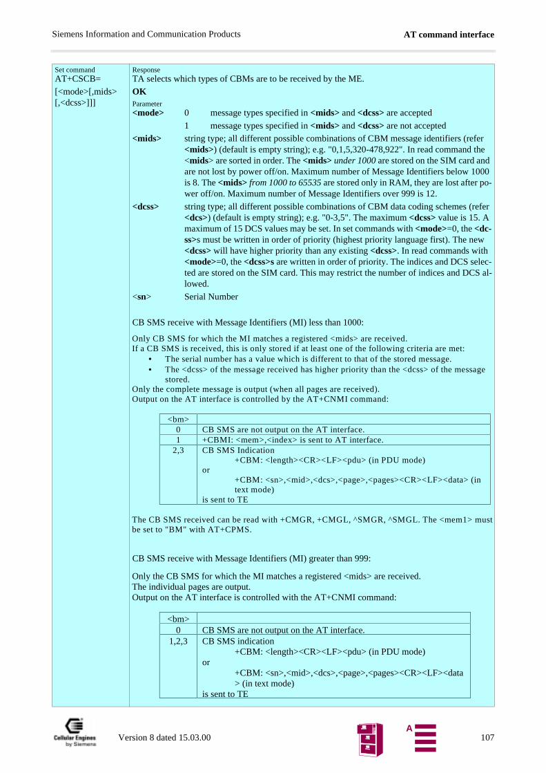
AT command interfaceSiemens Information and Communication Products
Set commandAT+CSCB=
[<mode>[,mids>[,<dcss>]]]
ResponseTA selects which types of CBMs are to be received by the ME.
OKParameter<mode> 0 message types specified in <mids> and <dcss> are accepted
1 message types specified in <mids> and <dcss> are not accepted
<mids> string type; all different possible combinations of CBM message identifiers (refer <mids>) (default is empty string); e.g. "0,1,5,320-478,922". In read command the <mids> are sorted in order. The <mids> under 1000 are stored on the SIM card and are not lost by power off/on. Maximum number of Message Identifiers below 1000 is 8. The <mids> from 1000 to 65535 are stored only in RAM, they are lost after po-wer off/on. Maximum number of Message Identifiers over 999 is 12.
<dcss> string type; all different possible combinations of CBM data coding schemes (refer <dcs>) (default is empty string); e.g. "0-3,5". The maximum <dcss> value is 15. A maximum of 15 DCS values may be set. In set commands with <mode>=0, the <dc-ss>s must be written in order of priority (highest priority language first). The new <dcss> will have higher priority than any existing <dcss>. In read commands with <mode>=0, the <dcss>s are written in order of priority. The indices and DCS selec-ted are stored on the SIM card. This may restrict the number of indices and DCS al-lowed.
<sn> Serial Number
CB SMS receive with Message Identifiers (MI) less than 1000:
CB SMS receive with Message Identifiers (MI) greater than 999:
Only CB SMS for which the MI matches a registered <mids> are received.If a CB SMS is received, this is only stored if at least one of the following criteria are met:
• The serial number has a value which is different to that of the stored message.• The <dcss> of the message received has higher priority than the <dcss> of the message
stored.Only the complete message is output (when all pages are received).Output on the AT interface is controlled by the AT+CNMI command:
<bm>0 CB SMS are not output on the AT interface.1 +CBMI: <mem>,<index> is sent to AT interface.
2,3 CB SMS Indication+CBM: <length><CR><LF><pdu> (in PDU mode)
or+CBM: <sn>,<mid>,<dcs>,<page>,<pages><CR><LF><data> (intext mode)
is sent to TE
The CB SMS received can be read with +CMGR, +CMGL, ^SMGR, ^SMGL. The <mem1> mustbe set to "BM" with AT+CPMS.
Only the CB SMS for which the MI matches a registered <mids> are received.The individual pages are output.Output on the AT interface is controlled with the AT+CNMI command:
<bm>0 CB SMS are not output on the AT interface.
1,2,3 CB SMS indication+CBM: <length><CR><LF><pdu> (in PDU mode)
or+CBM: <sn>,<mid>,<dcs>,<page>,<pages><CR><LF><data> (in text mode)
is sent to TE
Version 8 dated 15.03.00 107A
AT command interfaceSiemens Information and Communication Products
ReferenceGSM 07.05
NoteThe CB SMS may be output in text or PDU format. The output format is set with the command “AT+CMGF Select SMS message format” on page 94.
Message identifiers (MI) over 999 are intended for telemetric applications. These CB SMS are not stored permanently in the module, but are sent to the TE directly - taking account of the parameter <bm> in the “AT+CNMI New SMS message indications” command.
AT+CSDH Show SMS text mode parametersTest commandAT+CSDH=?
Response+CSDH: (list of supported <show>s) OKParametersee set command
Read commandAT+CSDH?
Response+CSDH:<show> OKParametersee set command
Set commandAT+CSDH=<show>
ResponseTA sets whether or not detailed header information is shown in text mode result codes.
OKParameter<show> 0 do not show header values defined in commands +CSCA and +CSMP
(<sca>, <tosca>, <fo>, <vp>, <pid> and <dcs>) nor <length>, <toda> or <tooa> in +CMT, +CMGL, +CMGR result codes for SMS-DELIVERs and SMS-SUBMITs in text mode; for SMS-COMMANDs in +CMGR result co-de, do not show <pid>, <mn>, <da>, <toda>, <length> or <cdata>
1 show the values in result codesReferenceGSM 07.05
Note
Version 8 dated 15.03.00 108A
AT command interfaceSiemens Information and Communication Products
AT+CSMP Set SMS text mode parametersTest commandAT+CSMP=?
ResponseOK
Read commandAT+CSMP?
Response+CSMP:<fo>,<vp>,<pid>,<dcs> OKParametersee set command
Set commandAT+CSMP=[<fo>[<vp>[,pid>[,<dcs>]]]]
ResponseTA selects values for additional parameters needed when SM is sent to the network or placed in a storage when text format message mode is selected. It is possible to set the validity period starting from when the SM is received by the SMSC (<vp> is in range 0... 255) or define the absolute time of the validity period termination (<vp> is a string).Parameter<fo> depending on the command or result code: first octet of GSM 03.40 SMS-DELIVER,
SMS-SUBMIT (default 17), or SMS-COMMAND (default 2) in integer format
<vp> depending on SMS-SUBMIT <fo> setting: GSM 03.40 TP-Validity-Period either in integer format (default 167)
<pid> Protocol-Identifier in integer format (default 0), refer GSM 03.40
<dcs> SMS Data Coding Scheme (default 0), or Cell Broadcast Data Coding Scheme in in-teger format depending on the command or result code: GSM 03.38
ReferenceGSM 07.05
NoteThe command writes the parameters in NON-VOLATILE memory with “AT+CSAS Save SMS set-tings”.
AT+CSMS Select Message ServiceTest commandAT+CSMS=?
Response+CSMS: (list of supported <service>s) OKParametersee set command
Read commandAT+CSMS?
Response+CSMS: <service>,<mt>,<mo>,<bm> OKParametersee set command
Set commandAT+CSMS= <ser-vice>
Response+CSMS: <mt>,<mo>,<bm> OKIf error is related to ME functionality:
+CMS ERROR: <err>Parameter<service> 0 GSM 03.40 and 03.41 (the syntax of SMS AT commands is compatible with
GSM 07.05 Phase 2 version 4.7.0; Phase 2+ features which do not require new command syntax may be supported (e.g. correct routing of messages with new Phase 2+ data coding schemes))
1 GSM 03.40 and 03.41 (the syntax of SMS AT commands is compatible with GSM 07.05 Phase 2+ version; the requirement of <service> setting 1 is men-tioned under corresponding command descriptions) Currently not available with the M20.
128 Compatibility to Phase 1 and to device type M1 (manufacturer specific)<mt> Mobile Terminated Messages:
0 Type not supported1 Type supported
<mo> Mobile Originated Messages:0 Type not supported1 Type supported
<bm> Broadcast Type Messages:0 Type not supported1 Type supported
Version 8 dated 15.03.00 109A

AT command interfaceSiemens Information and Communication Products
ReferenceGSM 07.05
Note
Version 8 dated 15.03.00 110A
AT command interfaceSiemens Information and Communication Products
5.7 Siemens-defined AT commands for enhanced functionsSelf-defined commands do not have to be implemented in accordance with the official syntax. The "+C" string can there-fore be replaced by "^S" ("^" = 0x5E). If a self-defined command with the same syntax is to be included in future in theGSM recommendations, the command can be addressed with both strings.
5.7.1 List of commands
Table 5-4 Siemens-defined AT commands
5.7.2 Detailed description
List of Siemens- defined commands
Function
AT^SACM Advice of Charge and query of ACM and ACMmax Page 111
AT^SCID Display SIM card identification number Page 113
AT^SCKS Set SIM conn. presentation. mode and query SIM conn. status Page 113
AT^SCNI List Call Number Information Page 114
AT^SCTM Set critical operating temp. present. mode or query temp. Page 114
AT^SLCK Facility lock (including Siemens-defined locks) Page 116
AT^SMGL List SMS messages from preferred storage without changing status to read Page 118
AT^SMGO Set or query SMS overflow present. mode or query SMS overflow Page 118
AT^SMGR Read SMS message without set to REC READ Page 119
AT^SMSO Switch off mobile station Page 122
AT^SNFA Set or query of microphone attenuation Page 122
AT^SNFE Set or query echo suppression parameters Page 123
AT^SNFI Set microphone path parameters Page 124
AT^SNFM Mute microphone Page 124
AT^SNFO Set or query audio output (= loudspeaker path) parameters Page 125
AT^SNFS Select audio hardware set Page 126
AT^SNFV Set or query loudspeaker volume Page 126
AT^SPIC Display PIN counter Page 126
AT^SPLM Read the PLMN list Page 126
AT^SPLR Read entry from the preferred operator list Page 127
AT^SPLW Write an entry to the preferred operator list Page 128
AT^SPWD Change password for a lock (including Siemens-defined locks) Page 130
AT^SRTC Select, query or test ringing tone Page 131
AT^MONI Monitor mode in Idle mode Page 133
AT^MONP Monitor neighbour cells Page 135
AT+CXXCID Display card ID (identical to AT^SCID) Page 136
AT^SACM Advice of charge and query of ACM and ACMmaxTest commandAT^SACM=?
Response^SACM: (list of supported <n>s) OKParametersee set command
Version 8 dated 15.03.00 111A
AT command interfaceSiemens Information and Communication Products
.g. as
re that
Read commandAT^SACM
ResponseTA returns the Advice of Charge supplementary service function mode and the SIM values for ac-cumulated call meter (ACM) and accumulated call meter maximum (ACMmax).
^SACM: <n>,<acm>,<acm_max> OKIf error is related to ME functionality:
+CME ERROR: <err>Parametersee set command
Set commandAT^SACM=<n>
ResponseTA sets the Advice of Charge supplementary service function mode.
OKParameter<n> 0 suppress unsolicited result code
1 display unsolicited result code
<acm> ACM, string type; three bytes of the current ACM value in hexadecimal for-mat (e.g. "00001E" indicates decimal value 30)
000000–FFFFFF
<acm_max> ACMmax, string type; three bytes of the max. ACM value in hexadecimalformat (e.g. "00001E" indicates decimal value 30)
000000
disable ACMmax feature
000001-FFFFFF
<ccm> string type; three bytes of the current CCM value in hexadecimal format (e"00001E" indicates decimal value 30); bytes are coded in the same way ACMmax value in the SIM
000000-FFFFFFUnsolicited result codeWhen activated, an unsolicited result code is sent when the CCM value changes, but not moevery 10 seconds
+CCCM: <ccm>Parametersee set command
ReferenceGSM07.07: AT+CACM, AT+CAMM, AT+CAOC
Note
Version 8 dated 15.03.00 112A
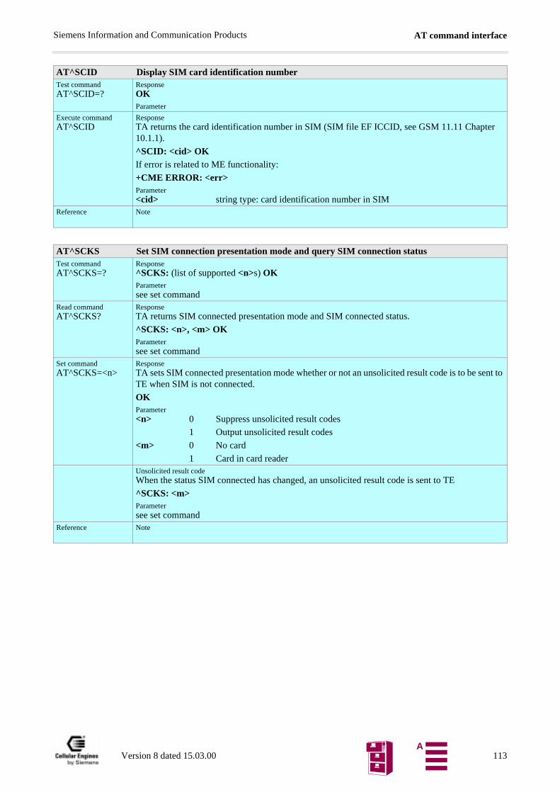
AT command interfaceSiemens Information and Communication Products
AT^SCID Display SIM card identification numberTest commandAT^SCID=?
ResponseOKParameter
Execute commandAT^SCID
ResponseTA returns the card identification number in SIM (SIM file EF ICCID, see GSM 11.11 Chapter 10.1.1).
^SCID: <cid> OKIf error is related to ME functionality:
+CME ERROR: <err>Parameter<cid> string type: card identification number in SIM
Reference
Note
AT^SCKS Set SIM connection presentation mode and query SIM connection statusTest commandAT^SCKS=?
Response^SCKS: (list of supported <n>s) OKParametersee set command
Read commandAT^SCKS?
ResponseTA returns SIM connected presentation mode and SIM connected status.
^SCKS: <n>, <m> OKParametersee set command
Set commandAT^SCKS=<n>
ResponseTA sets SIM connected presentation mode whether or not an unsolicited result code is to be sent to TE when SIM is not connected.
OKParameter<n> 0 Suppress unsolicited result codes
1 Output unsolicited result codes
<m> 0 No card
1 Card in card readerUnsolicited result codeWhen the status SIM connected has changed, an unsolicited result code is sent to TE
^SCKS: <m>Parametersee set command
Reference Note
Version 8 dated 15.03.00 113A

AT command interfaceSiemens Information and Communication Products
20-
AT^SCNI List Call Number InformationTest command AT^SCNI=?
ResponseOK
Execute commandAT^SCNI
Response TA returns a list of current calls of ME.
[^SCNI: <id1>[,<cs>[,<number>,<type>]]][^SCNI: <id2>[,<cs>[,<number>,<type>]]][...] OKIf error is related to ME functionality:
+CME ERROR: <err>Parameter<idx> integer type; call identification number as described in GSM
02.30[19] subclause 4.5.5.1; this number can be used in+CHLD command operations
1-7
<cs> Call status of respective call number (first parameter)0 call hold1 call in progress2 Waiting call
<number> string type phone number in format specified by <type><type> type of address octet in integer format; 145 when dialling
string includes international access code character "+", otherwise 129
ReferenceSiemens,GSM 07.07: AT+CLCC
Note
AT^SCTM Set critical operating temp. present. mode or query temp.Test command
AT^SCTM=?Response^SCTM: (list of supported <n>s) OKParametersee set command
Read commandAT^SCTM?
ResponseTA returns setting critical operating temperature presentation mode and temperature data
^SCTM: <n>, <m> OKParametersee set command
Set commandAT^SCTM=<n>
ResponseTA sets critical operating temperature presentation mode
OKParameter<n> 0 Suppress unsolicited result codes
1 Output unsolicited result codes
<m> 0 Below critical temperature
1 Above critical temperature (message issued when temperature of the M20-PCB is > 75°C)
2 Device switched off (this message is issued when the temperature of the MPCB is > 80°C), device immediately deregisters and switches off.
Unsolicited result codeWhen the temperature data has changed, an unsolicited result code is sent to TE
^SCTM: <m>Parametersee set command
ReferenceGSM Engine A1
Note
Important: The device switches off (like AT^SMSO) even if <n> is 0 and user is not informed.
Version 8 dated 15.03.00 114A
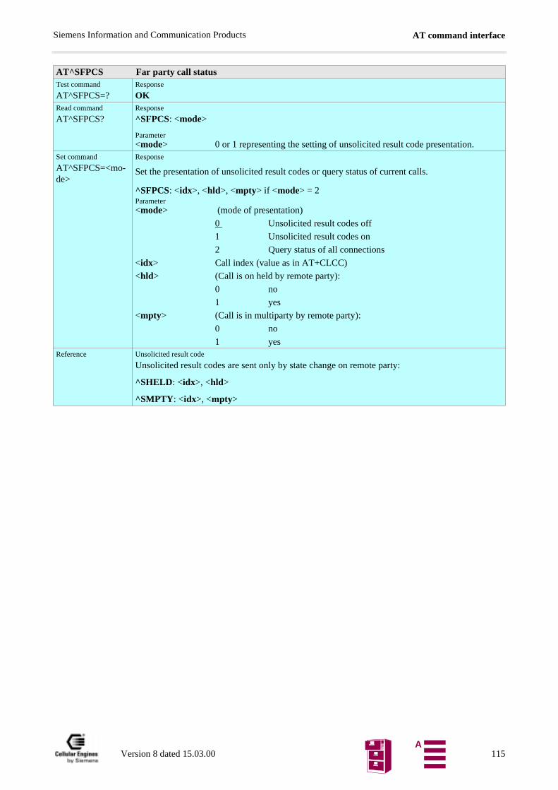
AT command interfaceSiemens Information and Communication Products
AT^SFPCS Far party call statusTest command
AT^SFPCS=?Response
OKRead command
AT^SFPCS?Response
^SFPCS: <mode>
Parameter<mode> 0 or 1 representing the setting of unsolicited result code presentation.
Set command
AT^SFPCS=<mo-de>
Response
Set the presentation of unsolicited result codes or query status of current calls.
^SFPCS: <idx>, <hld>, <mpty> if <mode> = 2Parameter<mode> (mode of presentation)
0 Unsolicited result codes off
1 Unsolicited result codes on
2 Query status of all connections
<idx> Call index (value as in AT+CLCC)
<hld> (Call is on held by remote party):
0 no
1 yes
<mpty> (Call is in multiparty by remote party):
0 no
1 yesReference Unsolicited result code
Unsolicited result codes are sent only by state change on remote party:
^SHELD: <idx>, <hld>
^SMPTY: <idx>, <mpty>
Version 8 dated 15.03.00 115A
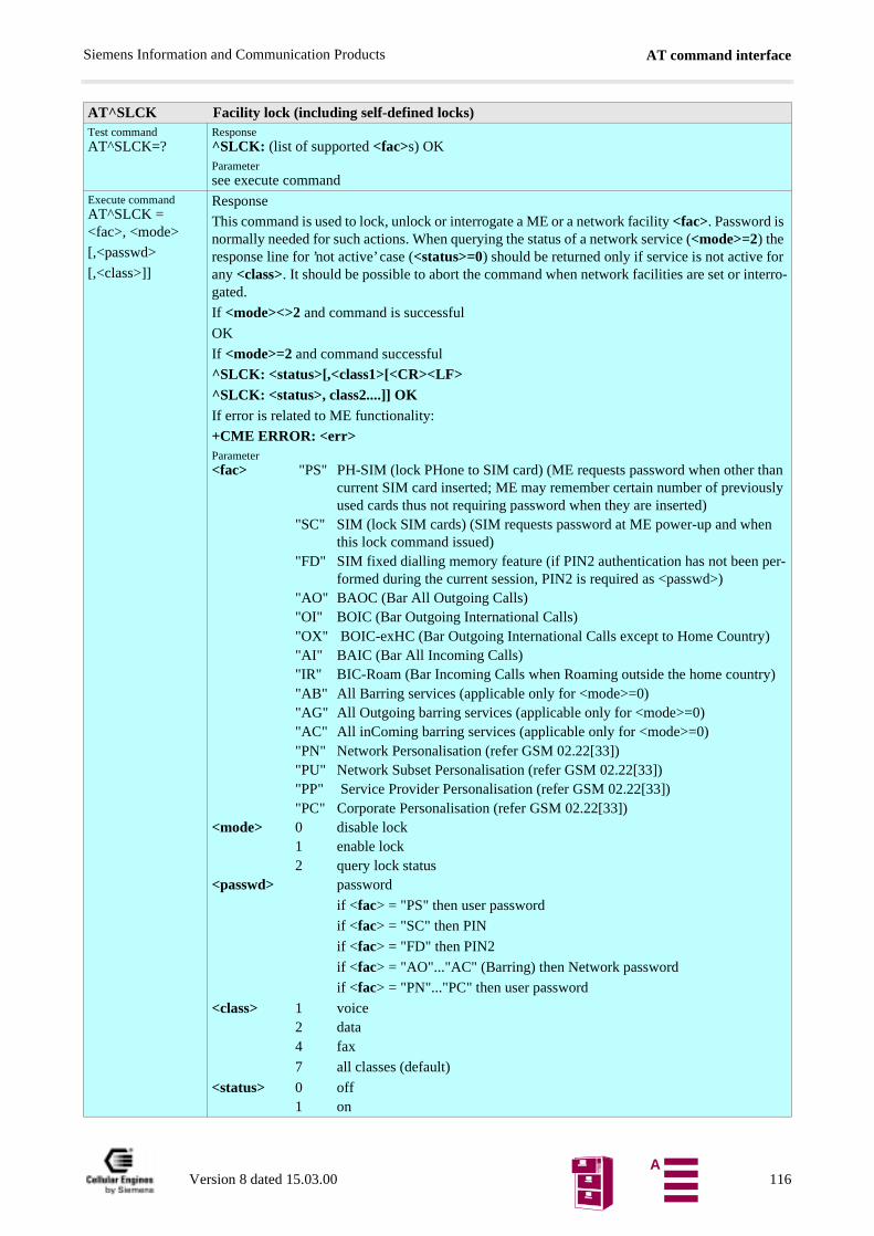
AT command interfaceSiemens Information and Communication Products
AT^SLCK Facility lock (including self-defined locks)Test commandAT^SLCK=?
Response^SLCK: (list of supported <fac>s) OKParametersee execute command
Execute commandAT^SLCK = <fac>, <mode>
[,<passwd>
[,<class>]]
Response
This command is used to lock, unlock or interrogate a ME or a network facility <fac>. Password is normally needed for such actions. When querying the status of a network service (<mode>=2) the response line for ’not active’ case (<status>=0) should be returned only if service is not active for any <class>. It should be possible to abort the command when network facilities are set or interro-gated.
If <mode><>2 and command is successful
OK
If <mode>=2 and command successful
^SLCK: <status>[,<class1>[<CR><LF>^SLCK: <status>, class2....]] OKIf error is related to ME functionality:
+CME ERROR: <err>Parameter<fac> "PS" PH-SIM (lock PHone to SIM card) (ME requests password when other than
current SIM card inserted; ME may remember certain number of previously used cards thus not requiring password when they are inserted)
"SC" SIM (lock SIM cards) (SIM requests password at ME power-up and when this lock command issued)
"FD" SIM fixed dialling memory feature (if PIN2 authentication has not been per-formed during the current session, PIN2 is required as <passwd>)
"AO" BAOC (Bar All Outgoing Calls)"OI" BOIC (Bar Outgoing International Calls)"OX" BOIC-exHC (Bar Outgoing International Calls except to Home Country)"AI" BAIC (Bar All Incoming Calls)"IR" BIC-Roam (Bar Incoming Calls when Roaming outside the home country)"AB" All Barring services (applicable only for <mode>=0)"AG" All Outgoing barring services (applicable only for <mode>=0)"AC" All inComing barring services (applicable only for <mode>=0)"PN" Network Personalisation (refer GSM 02.22[33])"PU" Network Subset Personalisation (refer GSM 02.22[33])"PP" Service Provider Personalisation (refer GSM 02.22[33])"PC" Corporate Personalisation (refer GSM 02.22[33])
<mode> 0 disable lock1 enable lock2 query lock status
<passwd> password
if <fac> = "PS" then user password
if <fac> = "SC" then PIN
if <fac> = "FD" then PIN2
if <fac> = "AO"..."AC" (Barring) then Network password
if <fac> = "PN"..."PC" then user password
<class> 1 voice 2 data4 fax
7 all classes (default)
<status> 0 off1 on
Version 8 dated 15.03.00 116A
AT command interfaceSiemens Information and Communication Products
ReferenceGSM 07.07: AT+CLCK
Note
Version 8 dated 15.03.00 117A
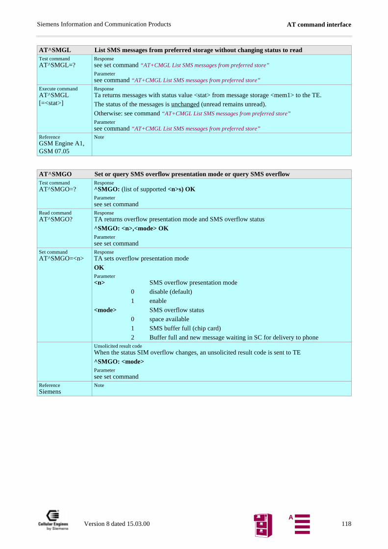
AT command interfaceSiemens Information and Communication Products
AT^SMGL List SMS messages from preferred storage without changing status to readTest commandAT^SMGL=?
Responsesee set command “AT+CMGL List SMS messages from preferred store”
Parametersee command “AT+CMGL List SMS messages from preferred store”
Execute commandAT^SMGL [=<stat>]
ResponseTa returns messages with status value <stat> from message storage <mem1> to the TE.
The status of the messages is unchanged (unread remains unread).
Otherwise: see command “AT+CMGL List SMS messages from preferred store”
Parametersee command “AT+CMGL List SMS messages from preferred store”
ReferenceGSM Engine A1, GSM 07.05
Note
AT^SMGO Set or query SMS overflow presentation mode or query SMS overflowTest commandAT^SMGO=?
Response^SMGO: (list of supported <n>s) OKParametersee set command
Read commandAT^SMGO?
ResponseTA returns overflow presentation mode and SMS overflow status
^SMGO: <n>,<mode> OKParametersee set command
Set commandAT^SMGO=<n>
ResponseTA sets overflow presentation mode
OKParameter<n> SMS overflow presentation mode
0 disable (default)
1 enable
<mode> SMS overflow status
0 space available
1 SMS buffer full (chip card)
2 Buffer full and new message waiting in SC for delivery to phoneUnsolicited result codeWhen the status SIM overflow changes, an unsolicited result code is sent to TE
^SMGO: <mode>Parametersee set command
ReferenceSiemens
Note
Version 8 dated 15.03.00 118A
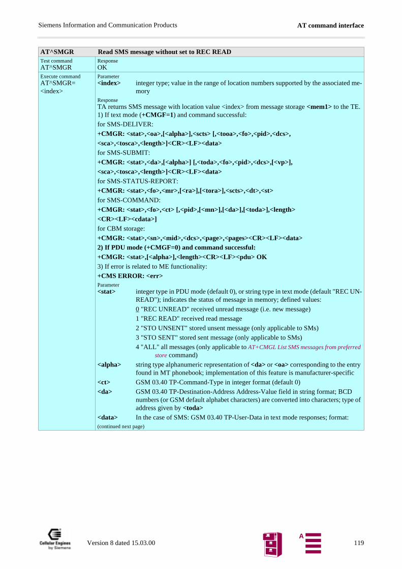
AT command interfaceSiemens Information and Communication Products
AT^SMGR Read SMS message without set to REC READTest commandAT^SMGR
ResponseOK
Execute commandAT^SMGR=<index>
Parameter<index> integer type; value in the range of location numbers supported by the associated me-
moryResponseTA returns SMS message with location value <index> from message storage <mem1> to the TE. 1) If text mode (+CMGF=1) and command successful:
for SMS-DELIVER:
+CMGR: <stat>,<oa>,[<alpha>],<scts> [,<tooa>,<fo>,<pid>,<dcs>,<sca>,<tosca>,<length>]<CR><LF><data>for SMS-SUBMIT:
+CMGR: <stat>,<da>,[<alpha>] [,<toda>,<fo>,<pid>,<dcs>,[<vp>],<sca>,<tosca>,<length>]<CR><LF><data>for SMS-STATUS-REPORT:
+CMGR: <stat>,<fo>,<mr>,[<ra>],[<tora>],<scts>,<dt>,<st>for SMS-COMMAND:
+CMGR: <stat>,<fo>,<ct> [,<pid>,[<mn>],[<da>],[<toda>],<length><CR><LF><cdata>]for CBM storage:
+CMGR: <stat>,<sn>,<mid>,<dcs>,<page>,<pages><CR><LF><data>2) If PDU mode (+CMGF=0) and command successful:+CMGR: <stat>,[<alpha>],<length><CR><LF><pdu> OK3) If error is related to ME functionality:
+CMS ERROR: <err>Parameter<stat> integer type in PDU mode (default 0), or string type in text mode (default "REC UN-
READ"); indicates the status of message in memory; defined values:
0 "REC UNREAD" received unread message (i.e. new message)
1 "REC READ" received read message
2 "STO UNSENT" stored unsent message (only applicable to SMs)
3 "STO SENT" stored sent message (only applicable to SMs)
4 "ALL" all messages (only applicable to AT+CMGL List SMS messages from preferred store command)
<alpha> string type alphanumeric representation of <da> or <oa> corresponding to the entry found in MT phonebook; implementation of this feature is manufacturer-specific
<ct> GSM 03.40 TP-Command-Type in integer format (default 0)
<da> GSM 03.40 TP-Destination-Address Address-Value field in string format; BCD numbers (or GSM default alphabet characters) are converted into characters; type of address given by <toda>
<data> In the case of SMS: GSM 03.40 TP-User-Data in text mode responses; format:(continued next page)
Version 8 dated 15.03.00 119A

AT command interfaceSiemens Information and Communication Products
, nds
94/
R,
coun-
me-
pe of
e- nted
M n by
Parameter
-if <dcs> indicates that GSM 03.38 default alphabet is used and <fo> indicates that GSM 03.40 TP-User-Data-Header-Indication is not set: ME/TA converts GSM alphabet into cur-rent TE character set according to rules covered in Annex A
-if <dcs> indicates that 8-bit or UCS2 data coding scheme is used, or <fo> indicates that GSM 03.40 TP-User-Data-Header-Indication is set: ME/TA converts each 8-bit octet into hexadecimal numbers containing two IRA characters (e.g. octet with integer value 42 is presented to TE as two characters 2A (IRA 50 and 65))
In the case of CBS: GSM 03.41 CBM Content of Message in text mode responses; format:
- if <dcs> indicates that GSM 03.38 default alphabet is used:
ME/TA converts GSM alphabet into current TE character set according to rules co-vered in Annex A
-if <dcs> indicates that 8-bit or UCS2 data coding scheme is used: ME/TA converts each 8-bit octet into hexadecimal numbers containing two IRA characters
<dcs> depending on the command or result code: GSM 03.38 SMS Data Coding Scheme (default 0), or Cell Broadcast Data Coding Scheme in integer format
<cdata> GSM 03.40 TP-Command-Data in text mode responses; ME/TA converts each 8-bit octet into two IRA character long hexadecimal number (e.g. octet with integer value 42 is presented to TE as two characters 2A (IRA 50 and 65))
<dt> GSM 03.40 TP-Discharge-Time in time-string format: “yy/MM/dd,hh:mm:ss±zz”where characters indicate year (two last digits), month, day, hour, minutes, secoand time zone. For example, 6th of May 1994, 22:10:00 GMT+2 hours equals “05/06,22:10:00+08”
<fo> depending on the command or result code: first octet of GSM 03.40 SMS-DELIVESMS-SUBMIT (default 17), SMS-STATUS-REPORT, or SMS-COMMAND (de-fault 2) in integer format
<length> integer type value indicating in text mode (+CMGF=1) the length of the message body <data> (or <cdata>) in characters; or in PDU mode (+CMGF=0), the length of the actual TP data unit in octets (i.e. the RP layer SMSC address octets are notted in the length)
<index> integer type; value in the range of location numbers supported by the associatedmory
<mid> GSM 03.41 CBM Message Identifier in integer format
<mr> GSM 03.40 TP-Message-Reference in integer format
<oa> GSM 03.40 TP-Originating-Address Address-Value field in string format; BCD numbers (or GSM default alphabet characters) are converted into characters; tyaddress given by <tooa>
<page> GSM 03.41 CBM Page Parameter bits 4-7 in integer format
<pages> GSM 03.41 CBM Page Parameter bits 0-3 in integer format
<pdu> In the case of SMS: GSM 04.11 SC address followed by GSM 03.40 TPDU in hxadecimal format: ME/TA converts each octet of TP data unit into hexadecimalnumbers containing two IRA characters (e.g. octet with integer value 42 is preseto TE as two characters 2A (IRA 50 and 65)). In the case of CBS: <ra> GSM 03.40 TP-Recipient-Address Address-Value field in string format; BCD numbers (or GSdefault alphabet characters) are converted into characters; type of address give<tora>
(continued next page)
Version 8 dated 15.03.00 120A

AT command interfaceSiemens Information and Communication Products
<pid> GSM 03.40 TP-Protocol-Identifier in integer format (default 0)
<ra> GSM 03.40 TP-Recipient-Address Address-Value field in string format; BCD num-bers (or GSM default alphabet characters) are converted to characters of the currently selected TE character set (refer command AT+CSCS Select TE character set.); type of address given by <tora>
<sca> GSM 04.11 RP SC address Address-Value field in string format; BCD numbers (or GSM default alphabet characters) are converted to characters of the currently selec-ted TE character set (refer command AT+CSCS Select TE character set.); type of address given by <tosca>
<scts> GSM 03.40 TP-Service-Centre-Time-Stamp in time-string format (refer <dt>)
<sn> GSM 03.41 CBM Serial Number in integer format
<st> GSM 03.40 TP-Status in integer format
<toda> GSM 04.11 TP-Destination-Address Type-of-Address octet in integer format (when first character of <da> is + (IRA 43) default is 145, otherwise default is 129)
<tooa> GSM 04.11 TP-Originating-Address Type-of-Address octet in integer format (de-fault refer<toda>)
<tora> GSM 04.11 TP-Recipient-Address Type-of-Address octet in integer format (default refer<toda>)
<tosca> GSM 04.11 RP SC address Type-of-Address octet in integer format (default refer <toda>)
<vp> depending on SMS-SUBMIT <fo> setting: GSM 03.40 TP-Validity-Period either in integer format (default 167) or in time-string format (refer <dt>)
ReferenceGSM 07.05
NoteThe AT^SMGR command is a specific Siemens command with the same syntax as “AT+CMGR Read SMS message”. The only difference is that the SMS Message, which has REC_UNREAD sta-tus, is not overwritten to REC_READ.
Version 8 dated 15.03.00 121A
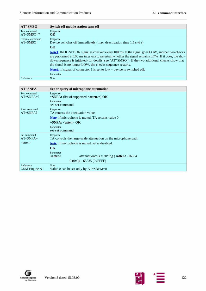
AT command interfaceSiemens Information and Communication Products
cks shut-hat
AT^SMSO Switch off mobile station turn offTest commandAT^SMSO=?
ResponseOK
Execute commandAT^SMSO
ResponseDevice switches off immediately (max. deactivation time 1.5 s–6 s)
OKNote1: the IGNITION signal is checked every 100 ms. If the signal goes LOW, another two cheare performed at 100 ms intervals to ascertain whether the signal remains LOW. If it does, thedown sequence is initiated (for details, see “AT^SMSO”). If the two additional checks show tthe signal is no longer LOW, the checks sequence restarts.
Note2: if signal of connector 1 is set to low = device is switched off.Parameter
Reference Note
AT^SNFA Set or query of microphone attenuationTest commandAT^SNFA=?
Response^SNFA: (list of supported <atten>s) OKParametersee set command
Read commandAT^SNFA?
ResponseTA returns the attenuation value.
Note: if microphone is muted, TA returns value 0.
^SNFA: <atten> OKParametersee set command
Set commandAT^SNFA=<atten>
ResponseTA controls the large-scale attenuation on the microphone path.
Note: if microphone is muted, set is disabled.
OKParameter<atten> attenuation/dB = 20*log (<atten> /16384
0 (0x0) – 65535 (0xFFFF)ReferenceGSM Engine A1
NoteValue 0 can be set only by AT^SNFM=0
Version 8 dated 15.03.00 122A
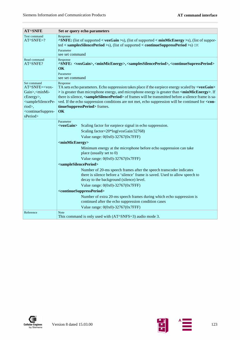
AT command interfaceSiemens Information and Communication Products
AT^SNFE Set or query echo parametersTest commandAT^SNFE=?
Response^SNFE: (list of supported < voxGain >s), (list of supported < minMicEnergy >s), (list of suppor-ted < samplesSilencePeriod >s), (list of supported < continueSuppressPeriod >s) OKParametersee set command
Read commandAT^SNFE?
Response^SNFE: <voxGain>, <minMicEnergy>, <samplesSilencePeriod>, <continueSupressPeriod> OKParametersee set command
Set commandAT^SNFE=<vox-Gain>,<minMi-cEnergy>,<sampleSilencePe-riod>,<continueSuppres-sPeriod>
ResponseTA sets echo parameters. Echo suppression takes place if the earpiece energy scaled by <voxGain> > is greater than microphone energy, and microphone energy is greater than <minMicEnergy>. If there is silence, <sampleSilencePeriod> of frames will be transmitted before a silence frame is sa-ved. If the echo suppression conditions are not met, echo suppression will be continued for <con-tinueSuppressPeriod> frames.OK
Parameter<voxGain> Scaling factor for earpiece signal in echo suppression.
Scaling factor=20*log(voxGain/32768)
Value range: 0(0x0)-32767(0x7FFF)
<minMicEnergy>Minimum energy at the microphone before echo suppression can takeplace (usually set to 0)
Value range: 0(0x0)-32767(0x7FFF)
<sampleSilencePeriod>Number of 20-ms speech frames after the speech transcoder indicatesthere is silence before a ‘silence’ frame is saved. Used to allow speech to decay to the background (silence) level.
Value range: 0(0x0)-32767(0x7FFF)
<continueSuppressPeriod>Number of extra 20-ms speech frames during which echo suppression iscontinued after the echo suppression condition cases
Value range: 0(0x0)-32767(0x7FFF)Reference Note
This command is only used with (AT^SNFS=3) audio mode 3.
Version 8 dated 15.03.00 123A
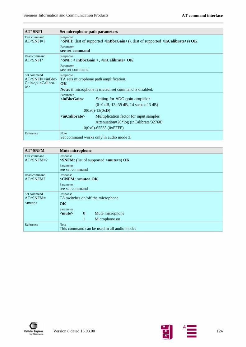
AT command interfaceSiemens Information and Communication Products
AT^SNFI Set microphone path parametersTest commandAT^SNFI=?
Response^SNFI: (list of supported <inBbcGain>s), (list of supported <inCalibrate>s) OKParametersee set command
Read commandAT^SNFI?
Response^SNF: < inBbcGain >, <inCalibrate> OKParametersee set command
Set commandAT^SNFI=<inBbc-Gain>,<inCalibra-te>
ResponseTA sets microphone path amplification.OKNote: if microphone is muted, set command is disabled.Parameter<inBbcGain> Setting for ADC gain amplifier
(0=0 dB, 13=39 dB, 14 steps of 3 dB)
0(0x0)-13(0xD)
<inCalibrate> Multiplication factor for input samples
Attenuation=20*log (inCalibrate/32768)
0(0x0)-65535 (0xFFFF)Reference Note
Set command works only in audio mode 3.
AT^SNFM Mute microphoneTest commandAT^SNFM=?
Response^SNFM: (list of supported <mute>s) OKParametersee set command
Read commandAT^SNFM?
Response^CNFM: <mute> OKParametersee set command
Set commandAT^SNFM=<mute>
ResponseTA switches on/off the microphone
OKParameter<mute> 0 Mute microphone
1 Microphone onReference Note
This command can be used in all audio modes
Version 8 dated 15.03.00 124A
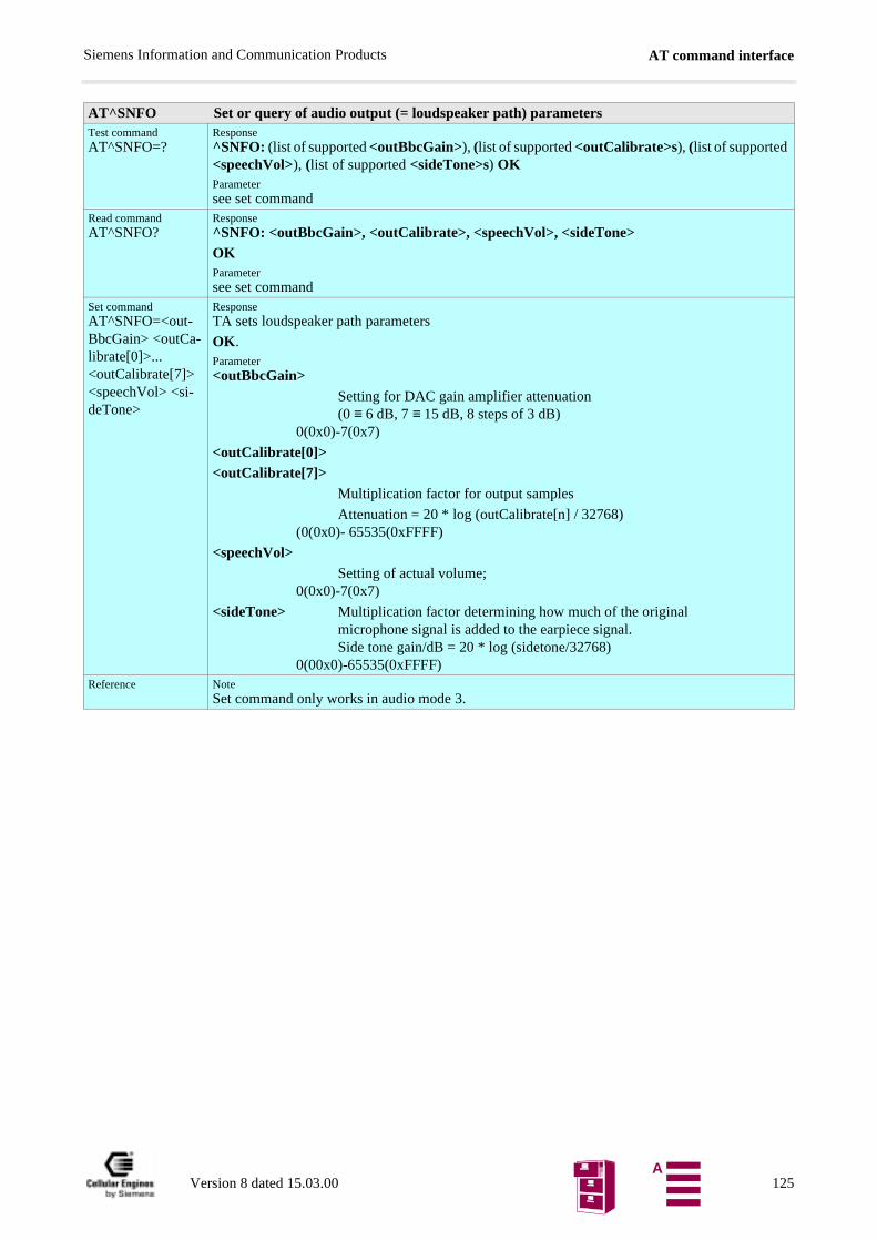
AT command interfaceSiemens Information and Communication Products
AT^SNFO Set or query of audio output (= loudspeaker path) parametersTest commandAT^SNFO=?
Response^SNFO: (list of supported <outBbcGain>), (list of supported <outCalibrate>s), (list of supported <speechVol>), (list of supported <sideTone>s) OKParametersee set command
Read commandAT^SNFO?
Response^SNFO: <outBbcGain>, <outCalibrate>, <speechVol>, <sideTone>OKParametersee set command
Set commandAT^SNFO=<out-BbcGain> <outCa-librate[0]>... <outCalibrate[7]> <speechVol> <si-deTone>
ResponseTA sets loudspeaker path parameters
OK.Parameter<outBbcGain>
Setting for DAC gain amplifier attenuation(0 ≡ 6 dB, 7 ≡ 15 dB, 8 steps of 3 dB)
0(0x0)-7(0x7)
<outCalibrate[0]><outCalibrate[7]>
Multiplication factor for output samples
Attenuation = 20 * log (outCalibrate[n] / 32768)(0(0x0)- 65535(0xFFFF)
<speechVol> Setting of actual volume;0(0x0)-7(0x7)
<sideTone> Multiplication factor determining how much of the originalmicrophone signal is added to the earpiece signal.Side tone gain/dB = 20 * log (sidetone/32768)
0(00x0)-65535(0xFFFF)Reference Note
Set command only works in audio mode 3.
Version 8 dated 15.03.00 125A
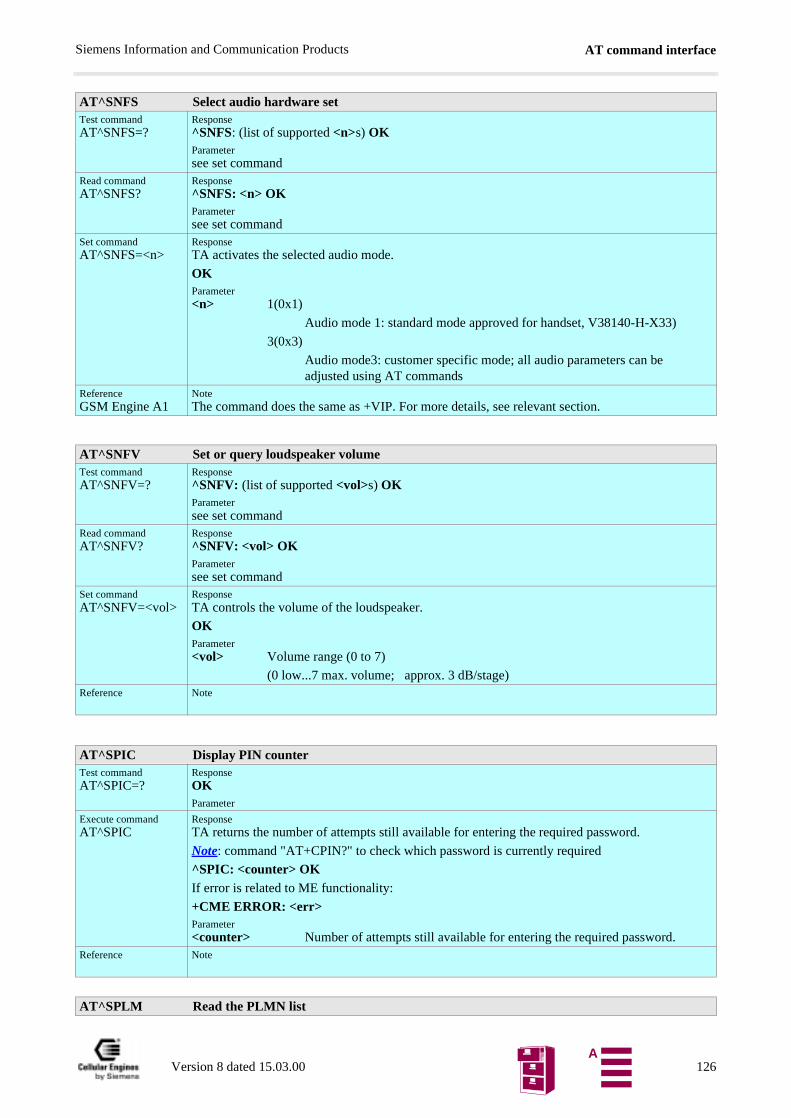
AT command interfaceSiemens Information and Communication Products
AT^SNFS Select audio hardware setTest commandAT^SNFS=?
Response^SNFS: (list of supported <n>s) OKParametersee set command
Read commandAT^SNFS?
Response^SNFS: <n> OKParametersee set command
Set commandAT^SNFS=<n>
ResponseTA activates the selected audio mode.
OKParameter<n> 1(0x1)
Audio mode 1: standard mode approved for handset, V38140-H-X33)
3(0x3)
Audio mode3: customer specific mode; all audio parameters can beadjusted using AT commands
ReferenceGSM Engine A1
NoteThe command does the same as +VIP. For more details, see relevant section.
AT^SNFV Set or query loudspeaker volumeTest commandAT^SNFV=?
Response^SNFV: (list of supported <vol>s) OKParametersee set command
Read commandAT^SNFV?
Response^SNFV: <vol> OKParametersee set command
Set commandAT^SNFV=<vol>
ResponseTA controls the volume of the loudspeaker.
OKParameter<vol> Volume range (0 to 7)
(0 low...7 max. volume; approx. 3 dB/stage)Reference Note
AT^SPIC Display PIN counterTest commandAT^SPIC=?
ResponseOKParameter
Execute commandAT^SPIC
ResponseTA returns the number of attempts still available for entering the required password.
Note: command "AT+CPIN?" to check which password is currently required
^SPIC: <counter> OKIf error is related to ME functionality:
+CME ERROR: <err>Parameter<counter> Number of attempts still available for entering the required password.
Reference Note
AT^SPLM Read the PLMN list
Version 8 dated 15.03.00 126A
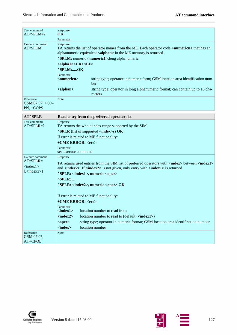
AT command interfaceSiemens Information and Communication Products
Test commandAT^SPLM=?
ResponseOKParameter
Execute commandAT^SPLM
ResponseTA returns the list of operator names from the ME. Each operator code <numericn> that has an alphanumeric equivalent <alphan> in the ME memory is returned.
^SPLM: numeric <numeric1>,long alphanumeric
<alpha1><CR><LF>^SPLM:.....OKParameter<numericn> string type; operator in numeric form; GSM location area identification num-
ber
<alphan> string type; operator in long alphanumeric format; can contain up to 16 cha-racters
ReferenceGSM 07.07: +CO-PN, +COPS
Note
AT^SPLR Read entry from the preferred operator listTest commandAT^SPLR=?
ResponseTA returns the whole index range supported by the SIM.
^SPLR (list of supported <index>s) OKIf error is related to ME functionality:
+CME ERROR: <err>Parametersee execute command
Execute commandAT^SPLR=
<index1> [,<index2>]
Response
TA returns used entries from the SIM list of preferred operators with <index> between <index1>and <index2>. If <index2> is not given, only entry with <index1> is returned.
^SPLR: <index1>, numeric <oper>^SPLR: ...^SPLR: <index2>, numeric <oper> OK
If error is related to ME functionality:
+CME ERROR: <err>Parameter<index1> location number to read from
<index2> location number to read to (default: <index1>)
<oper> string type; operator in numeric format; GSM location area identification number
<index> location numberReferenceGSM 07.07, AT+CPOL
Note:
Version 8 dated 15.03.00 127A
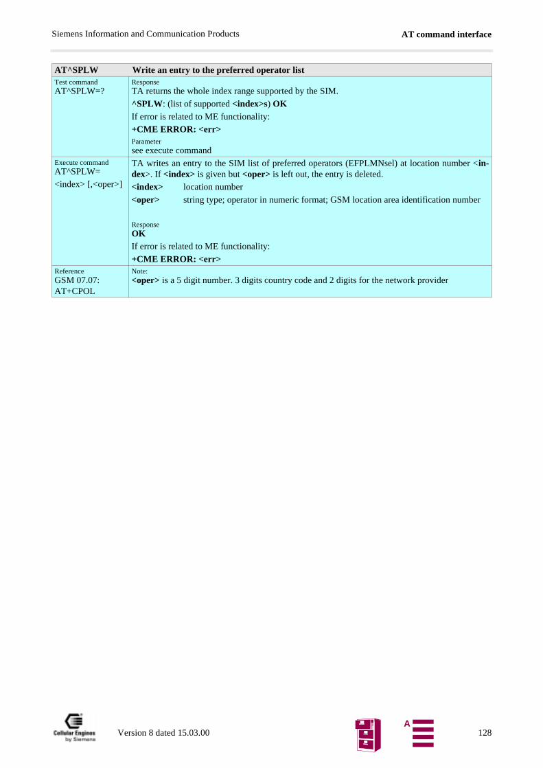
AT command interfaceSiemens Information and Communication Products
AT^SPLW Write an entry to the preferred operator listTest commandAT^SPLW=?
ResponseTA returns the whole index range supported by the SIM.
^SPLW: (list of supported <index>s) OKIf error is related to ME functionality:
+CME ERROR: <err>Parametersee execute command
Execute commandAT^SPLW=
<index> [,<oper>]
TA writes an entry to the SIM list of preferred operators (EFPLMNsel) at location number <in-dex>. If <index> is given but <oper> is left out, the entry is deleted.
<index> location number
<oper> string type; operator in numeric format; GSM location area identification number
ResponseOKIf error is related to ME functionality:
+CME ERROR: <err>ReferenceGSM 07.07: AT+CPOL
Note: <oper> is a 5 digit number. 3 digits country code and 2 digits for the network provider
Version 8 dated 15.03.00 128A
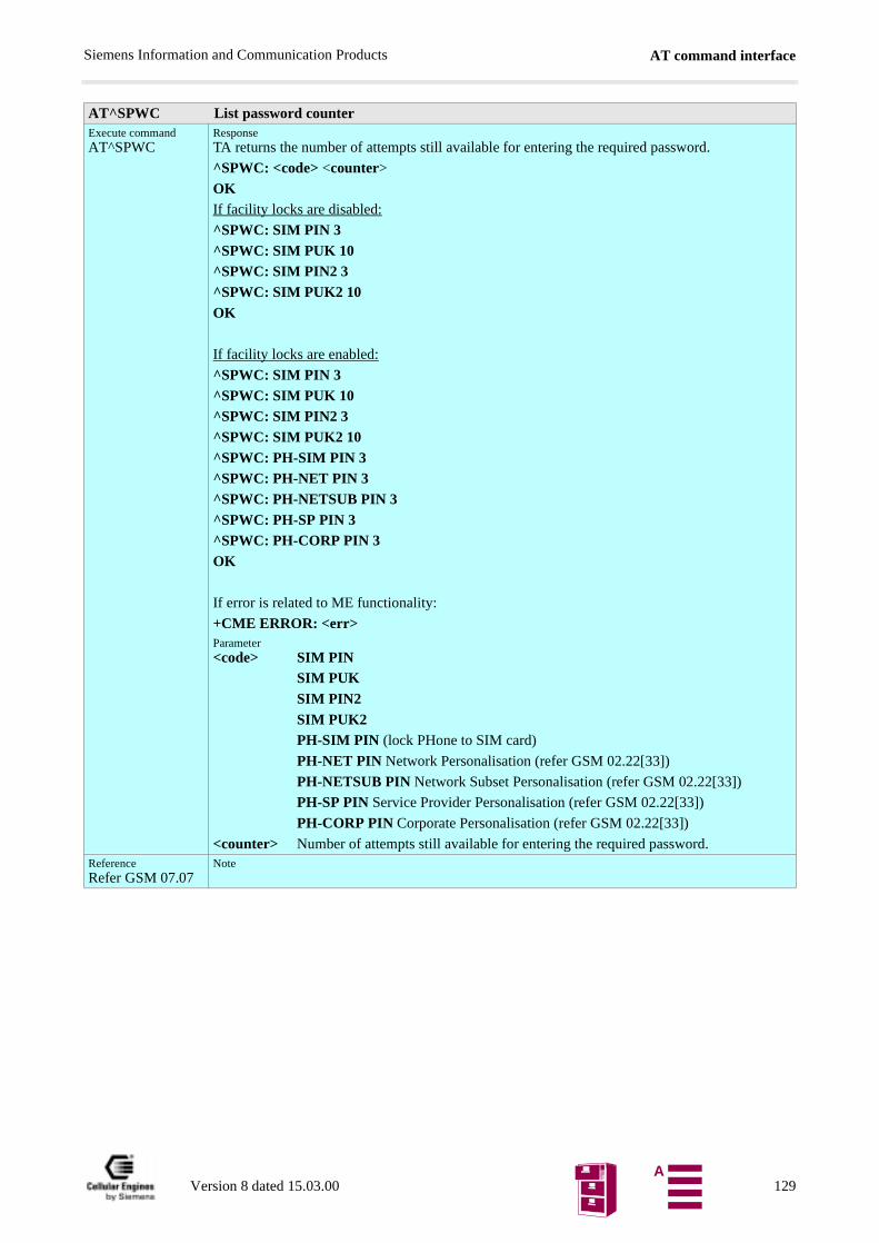
AT command interfaceSiemens Information and Communication Products
AT^SPWC List password counterExecute commandAT^SPWC
ResponseTA returns the number of attempts still available for entering the required password.
^SPWC: <code> <counter>
OKIf facility locks are disabled:
^SPWC: SIM PIN 3^SPWC: SIM PUK 10^SPWC: SIM PIN2 3^SPWC: SIM PUK2 10OK
If facility locks are enabled:
^SPWC: SIM PIN 3^SPWC: SIM PUK 10^SPWC: SIM PIN2 3^SPWC: SIM PUK2 10^SPWC: PH-SIM PIN 3^SPWC: PH-NET PIN 3^SPWC: PH-NETSUB PIN 3^SPWC: PH-SP PIN 3^SPWC: PH-CORP PIN 3OK
If error is related to ME functionality:
+CME ERROR: <err>Parameter<code> SIM PIN
SIM PUKSIM PIN2SIM PUK2PH-SIM PIN (lock PHone to SIM card)
PH-NET PIN Network Personalisation (refer GSM 02.22[33])
PH-NETSUB PIN Network Subset Personalisation (refer GSM 02.22[33])
PH-SP PIN Service Provider Personalisation (refer GSM 02.22[33])
PH-CORP PIN Corporate Personalisation (refer GSM 02.22[33])
<counter> Number of attempts still available for entering the required password.ReferenceRefer GSM 07.07
Note
Version 8 dated 15.03.00 129A
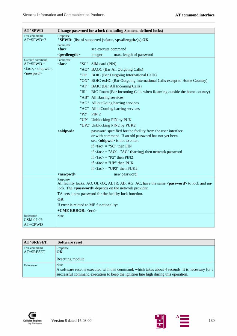
AT command interfaceSiemens Information and Communication Products
AT^SPWD Change password for a lock (including Siemens-defined locks)Test commandAT^SPWD=?
Response^SPWD: (list of supported (<fac>, <pwdlength>)s) OKParameter<fac> see execute command
<pwdlength> integer max. length of passwordExecute commandAT^SPWD = <fac>, <oldpwd>, <newpwd>
Parameter<fac> "SC" SIM card (PIN)
"AO" BAOC (Bar All Outgoing Calls)
"OI" BOIC (Bar Outgoing International Calls)
"OX" BOIC-exHC (Bar Outgoing International Calls except to Home Country)
"AI" BAIC (Bar All Incoming Calls)
"IR" BIC-Roam (Bar Incoming Calls when Roaming outside the home country)
"AB" All Barring services
"AG" All outGoing barring services
"AC" All inComing barring services
"P2" PIN 2
"UP" Unblocking PIN by PUK
"UP2" Unblocking PIN2 by PUK2
<oldpwd> password specified for the facility from the user interfaceor with command. If an old password has not yet beenset, <oldpwd> is not to enter.
if <fac> = "SC" then PIN
if <fac> = "AO"..."AC" (barring) then network password
if <fac> = "P2" then PIN2
if <fac> = "UP" then PUK
if <fac> = "UP2" then PUK2
<newpwd> new passwordResponseAll facility locks: AO, OI, OX, AI, IR, AB, AG, AC, have the same <password> to lock and un-lock. The <password> depends on the network provider.
TA sets a new password for the facility lock function.
OKIf error is related to ME functionality:
+CME ERROR: <err>ReferenceGSM 07.07: AT+CPWD
Note
AT^SRESET Software resetTest commandAT^SRESET
ResponseOK
Resetting module
Reference Note
A software reset is executed with this command, which takes about 4 seconds. It is necessary for asuccessful command execution to keep the ignition line high during this operation.
Version 8 dated 15.03.00 130A
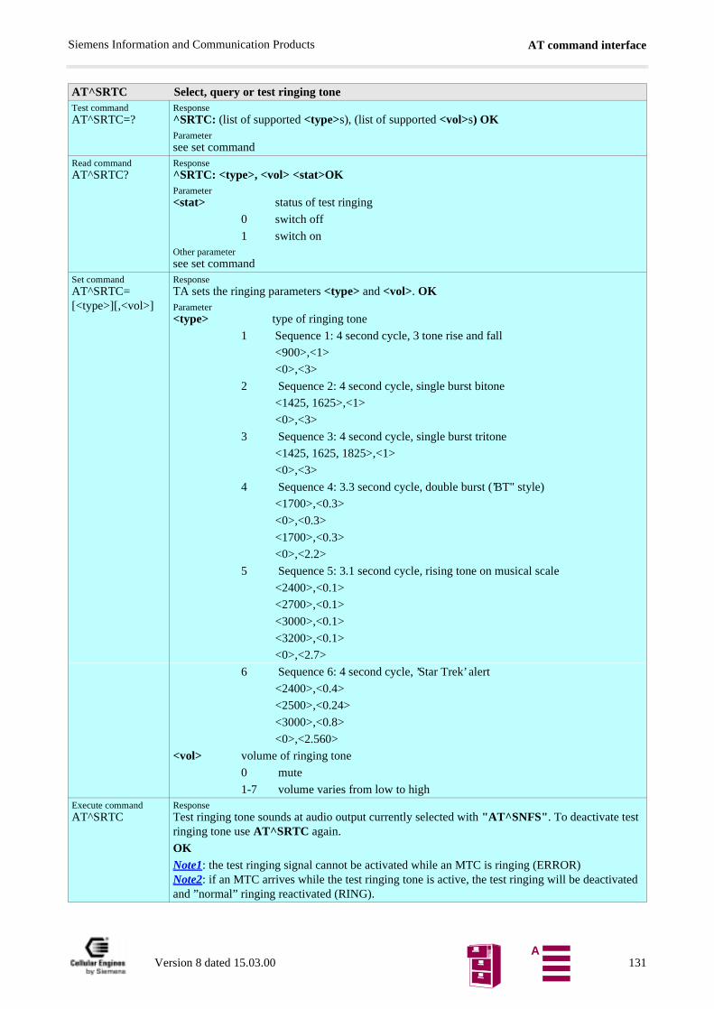
AT command interfaceSiemens Information and Communication Products
AT^SRTC Select, query or test ringing toneTest commandAT^SRTC=?
Response^SRTC: (list of supported <type>s), (list of supported <vol>s) OKParametersee set command
Read commandAT^SRTC?
Response^SRTC: <type>, <vol> <stat>OKParameter<stat> status of test ringing
0 switch off
1 switch onOther parametersee set command
Set commandAT^SRTC=[<type>][,<vol>]
ResponseTA sets the ringing parameters <type> and <vol>. OKParameter<type> type of ringing tone
1 Sequence 1: 4 second cycle, 3 tone rise and fall
<900>,<1>
<0>,<3>
2 Sequence 2: 4 second cycle, single burst bitone
<1425, 1625>,<1>
<0>,<3>
3 Sequence 3: 4 second cycle, single burst tritone
<1425, 1625, 1825>,<1>
<0>,<3>
4 Sequence 4: 3.3 second cycle, double burst (’BT" style)
<1700>,<0.3>
<0>,<0.3>
<1700>,<0.3>
<0>,<2.2>
5 Sequence 5: 3.1 second cycle, rising tone on musical scale
<2400>,<0.1>
<2700>,<0.1>
<3000>,<0.1>
<3200>,<0.1>
<0>,<2.7>
6 Sequence 6: 4 second cycle, ’Star Trek’ alert
<2400>,<0.4>
<2500>,<0.24>
<3000>,<0.8>
<0>,<2.560>
<vol> volume of ringing tone
0 mute
1-7 volume varies from low to highExecute commandAT^SRTC
ResponseTest ringing tone sounds at audio output currently selected with "AT^SNFS". To deactivate test ringing tone use AT^SRTC again.
OKNote1: the test ringing signal cannot be activated while an MTC is ringing (ERROR)Note2: if an MTC arrives while the test ringing tone is active, the test ringing will be deactivated and ”normal” ringing reactivated (RING).
Version 8 dated 15.03.00 131A
AT command interfaceSiemens Information and Communication Products
Reference Note
Version 8 dated 15.03.00 132A
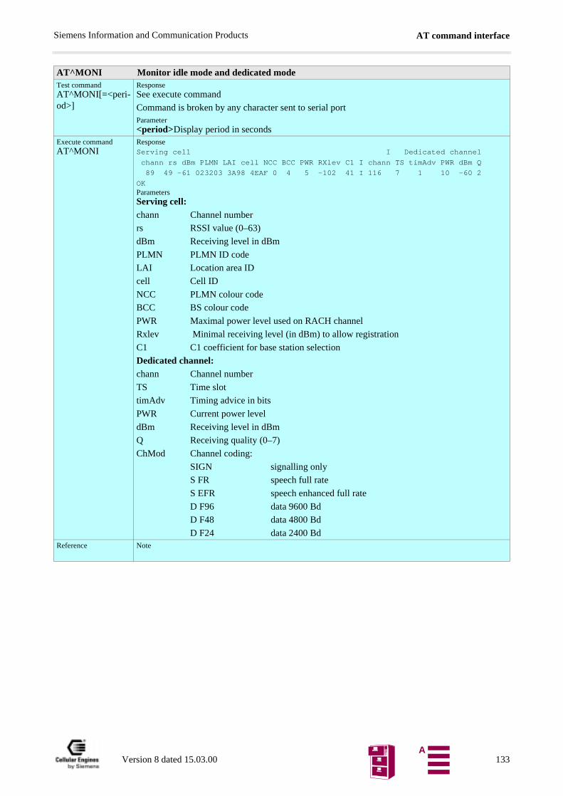
AT command interfaceSiemens Information and Communication Products
AT^MONI Monitor idle mode and dedicated modeTest commandAT^MONI[=<peri-od>]
ResponseSee execute command
Command is broken by any character sent to serial portParameter<period>Display period in seconds
Execute commandAT^MONI
ResponseServing cell I Dedicated channel
chann rs dBm PLMN LAI cell NCC BCC PWR RXlev C1 I chann TS timAdv PWR dBm Q
89 49 -61 023203 3A98 4EAF 0 4 5 -102 41 I 116 7 1 10 -60 2
OKParametersServing cell:chann Channel number
rs RSSI value (0–63)
dBm Receiving level in dBm
PLMN PLMN ID code
LAI Location area ID
cell Cell ID
NCC PLMN colour code
BCC BS colour code
PWR Maximal power level used on RACH channel
Rxlev Minimal receiving level (in dBm) to allow registration
C1 C1 coefficient for base station selection
Dedicated channel:chann Channel number
TS Time slot
timAdv Timing advice in bits
PWR Current power level
dBm Receiving level in dBm
Q Receiving quality (0–7)
ChMod Channel coding:
SIGN signalling only
S FR speech full rate
S EFR speech enhanced full rate
D F96 data 9600 Bd
D F48 data 4800 Bd
D F24 data 2400 BdReference Note
Version 8 dated 15.03.00 133A
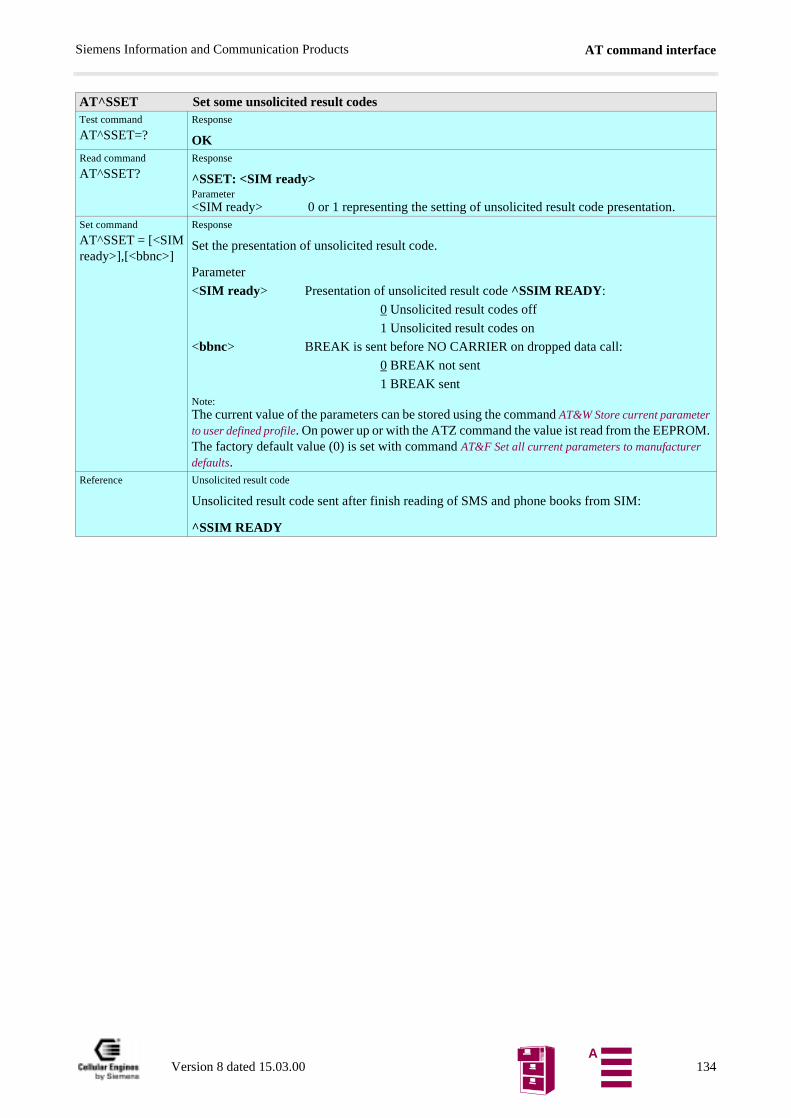
AT command interfaceSiemens Information and Communication Products
AT^SSET Set some unsolicited result codesTest command
AT^SSET=?Response
OKRead command
AT^SSET?Response
^SSET: <SIM ready>Parameter<SIM ready> 0 or 1 representing the setting of unsolicited result code presentation.
Set command
AT^SSET = [<SIMready>],[<bbnc>]
Response
Set the presentation of unsolicited result code.
Parameter
<SIM ready> Presentation of unsolicited result code ^SSIM READY:
0 Unsolicited result codes off
1 Unsolicited result codes on
<bbnc> BREAK is sent before NO CARRIER on dropped data call:
0 BREAK not sent
1 BREAK sentNote:The current value of the parameters can be stored using the command AT&W Store current parameter to user defined profile. On power up or with the ATZ command the value ist read from the EEPROM. The factory default value (0) is set with command AT&F Set all current parameters to manufacturer defaults.
Reference Unsolicited result code
Unsolicited result code sent after finish reading of SMS and phone books from SIM:
^SSIM READY
Version 8 dated 15.03.00 134A
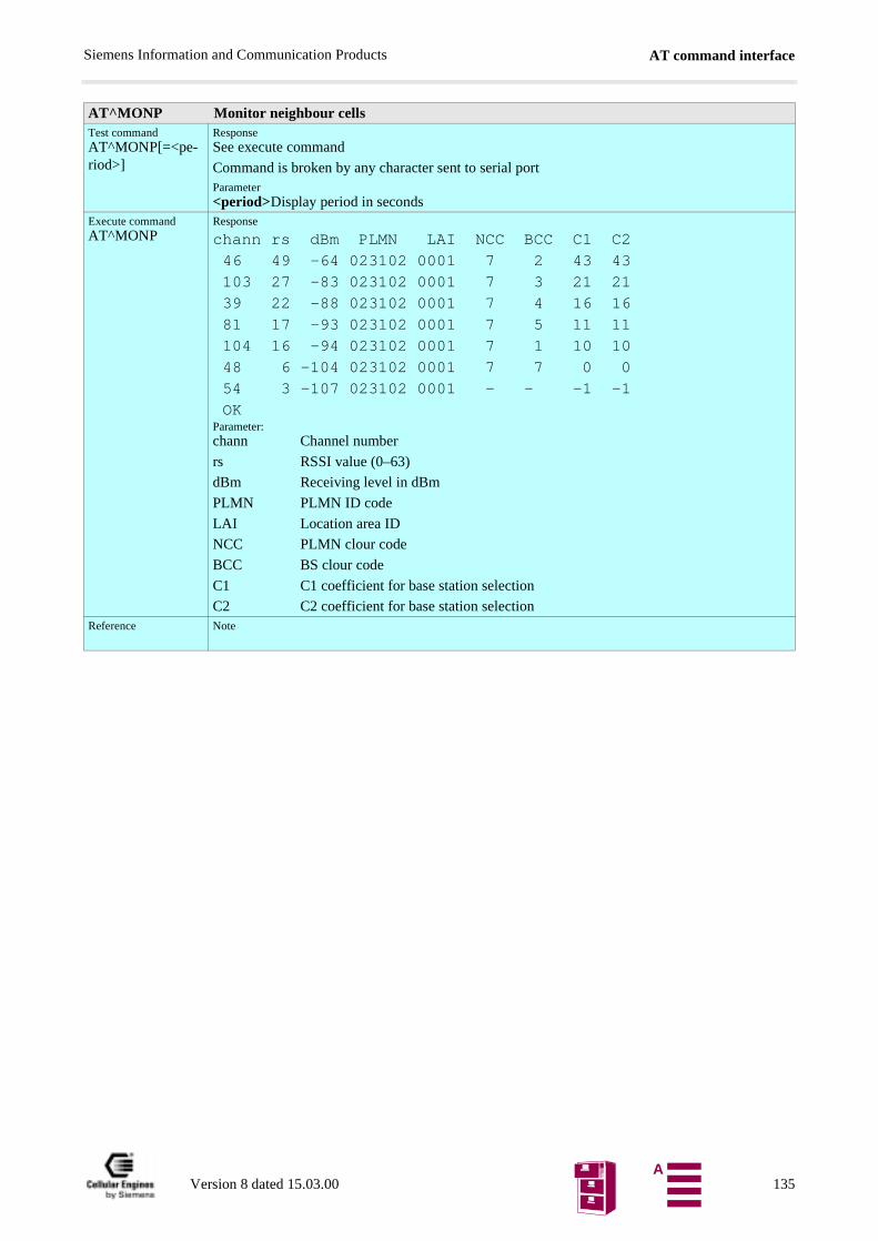
AT command interfaceSiemens Information and Communication Products
AT^MONP Monitor neighbour cellsTest commandAT^MONP[=<pe-riod>]
ResponseSee execute command
Command is broken by any character sent to serial portParameter<period>Display period in seconds
Execute commandAT^MONP
Response
chann rs dBm PLMN LAI NCC BCC C1 C2
46 49 -64 023102 0001 7 2 43 43 103 27 -83 023102 0001 7 3 21 21 39 22 -88 023102 0001 7 4 16 16
81 17 -93 023102 0001 7 5 11 11 104 16 -94 023102 0001 7 1 10 10
48 6 -104 023102 0001 7 7 0 0 54 3 -107 023102 0001 - - -1 -1 OKParameter:chann Channel number
rs RSSI value (0–63)
dBm Receiving level in dBm
PLMN PLMN ID code
LAI Location area ID
NCC PLMN clour code
BCC BS clour code
C1 C1 coefficient for base station selection
C2 C2 coefficient for base station selectionReference Note
Version 8 dated 15.03.00 135A
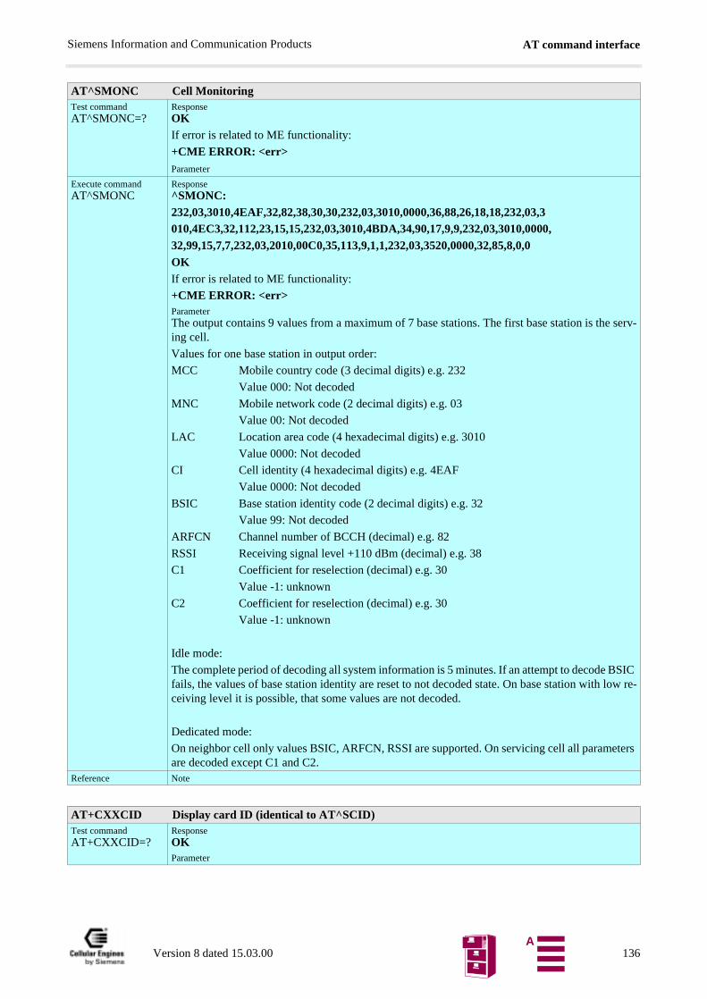
AT command interfaceSiemens Information and Communication Products
AT^SMONC Cell MonitoringTest commandAT^SMONC=?
ResponseOKIf error is related to ME functionality:
+CME ERROR: <err>Parameter
Execute commandAT^SMONC
Response^SMONC:232,03,3010,4EAF,32,82,38,30,30,232,03,3010,0000,36,88,26,18,18,232,03,3010,4EC3,32,112,23,15,15,232,03,3010,4BDA,34,90,17,9,9,232,03,3010,0000,32,99,15,7,7,232,03,2010,00C0,35,113,9,1,1,232,03,3520,0000,32,85,8,0,0OKIf error is related to ME functionality:
+CME ERROR: <err>ParameterThe output contains 9 values from a maximum of 7 base stations. The first base station is the serv-ing cell.
Values for one base station in output order:
MCC Mobile country code (3 decimal digits) e.g. 232
Value 000: Not decoded
MNC Mobile network code (2 decimal digits) e.g. 03
Value 00: Not decoded
LAC Location area code (4 hexadecimal digits) e.g. 3010
Value 0000: Not decoded
CI Cell identity (4 hexadecimal digits) e.g. 4EAF
Value 0000: Not decoded
BSIC Base station identity code (2 decimal digits) e.g. 32
Value 99: Not decoded
ARFCN Channel number of BCCH (decimal) e.g. 82
RSSI Receiving signal level +110 dBm (decimal) e.g. 38
C1 Coefficient for reselection (decimal) e.g. 30
Value -1: unknown
C2 Coefficient for reselection (decimal) e.g. 30
Value -1: unknown
Idle mode:
The complete period of decoding all system information is 5 minutes. If an attempt to decode BSIC fails, the values of base station identity are reset to not decoded state. On base station with low re-ceiving level it is possible, that some values are not decoded.
Dedicated mode:
On neighbor cell only values BSIC, ARFCN, RSSI are supported. On servicing cell all parameters are decoded except C1 and C2.
Reference Note
AT+CXXCID Display card ID (identical to AT^SCID)Test commandAT+CXXCID=?
ResponseOKParameter
Version 8 dated 15.03.00 136A
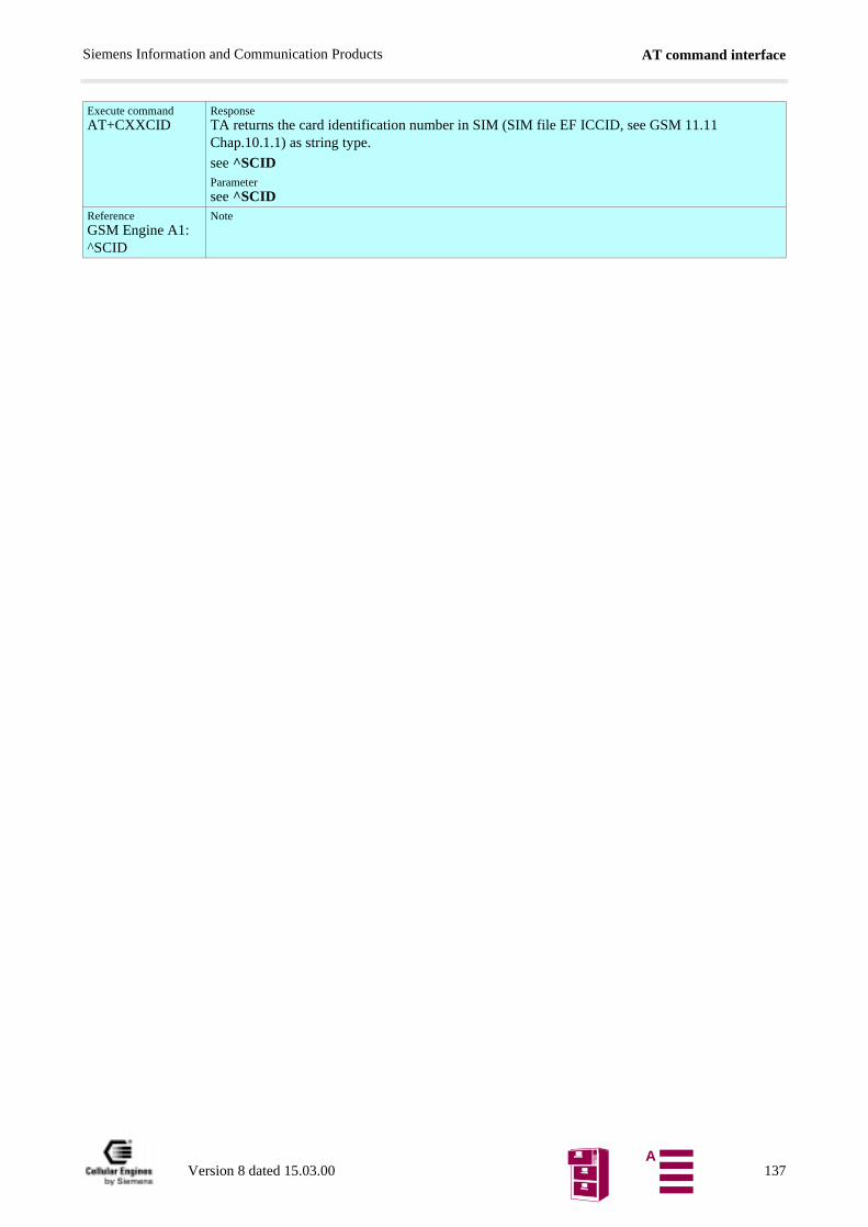
AT command interfaceSiemens Information and Communication Products
Execute commandAT+CXXCID
ResponseTA returns the card identification number in SIM (SIM file EF ICCID, see GSM 11.11 Chap.10.1.1) as string type.
see ^SCIDParametersee ^SCID
ReferenceGSM Engine A1: ^SCID
Note
Version 8 dated 15.03.00 137A
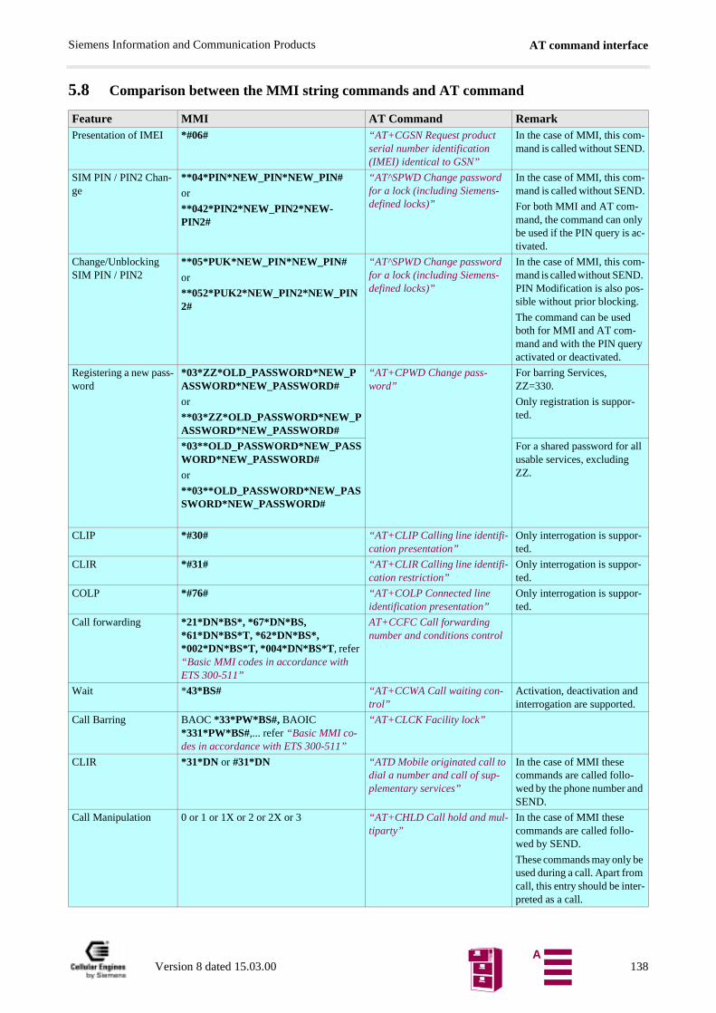
AT command interfaceSiemens Information and Communication Products
5.8 Comparison between the MMI string commands and AT command
Feature MMI AT Command RemarkPresentation of IMEI *#06# “AT+CGSN Request product
serial number identification (IMEI) identical to GSN”
In the case of MMI, this com-mand is called without SEND.
SIM PIN / PIN2 Chan-ge
**04*PIN*NEW_PIN*NEW_PIN#or
**042*PIN2*NEW_PIN2*NEW-PIN2#
“AT^SPWD Change password for a lock (including Siemens-defined locks)”
In the case of MMI, this com-mand is called without SEND.
For both MMI and AT com-mand, the command can only be used if the PIN query is ac-tivated.
Change/Unblocking SIM PIN / PIN2
**05*PUK*NEW_PIN*NEW_PIN#
or
**052*PUK2*NEW_PIN2*NEW_PIN2#
“AT^SPWD Change password for a lock (including Siemens-defined locks)”
In the case of MMI, this com-mand is called without SEND. PIN Modification is also pos-sible without prior blocking.
The command can be used both for MMI and AT com-mand and with the PIN query activated or deactivated.
Registering a new pass-word
*03*ZZ*OLD_PASSWORD*NEW_PASSWORD*NEW_PASSWORD#or
**03*ZZ*OLD_PASSWORD*NEW_PASSWORD*NEW_PASSWORD#
“AT+CPWD Change pass-word”
For barring Services, ZZ=330.
Only registration is suppor-ted.
*03**OLD_PASSWORD*NEW_PASSWORD*NEW_PASSWORD#or
**03**OLD_PASSWORD*NEW_PASSWORD*NEW_PASSWORD#
For a shared password for all usable services, excluding ZZ.
CLIP *#30# “AT+CLIP Calling line identifi-cation presentation”
Only interrogation is suppor-ted.
CLIR *#31# “AT+CLIR Calling line identifi-cation restriction”
Only interrogation is suppor-ted.
COLP *#76# “AT+COLP Connected line identification presentation”
Only interrogation is suppor-ted.
Call forwarding *21*DN*BS*, *67*DN*BS, *61*DN*BS*T, *62*DN*BS*, *002*DN*BS*T, *004*DN*BS*T, refer “Basic MMI codes in accordance with ETS 300-511”
AT+CCFC Call forwarding number and conditions control
Wait *43*BS# “AT+CCWA Call waiting con-trol”
Activation, deactivation and interrogation are supported.
Call Barring BAOC *33*PW*BS#, BAOIC *331*PW*BS#,... refer “Basic MMI co-des in accordance with ETS 300-511”
“AT+CLCK Facility lock”
CLIR *31*DN or #31*DN “ATD Mobile originated call to dial a number and call of sup-plementary services”
In the case of MMI these commands are called follo-wed by the phone number and SEND.
Call Manipulation 0 or 1 or 1X or 2 or 2X or 3 “AT+CHLD Call hold and mul-tiparty”
In the case of MMI these commands are called follo-wed by SEND.
These commands may only be used during a call. Apart from call, this entry should be inter-preted as a call.
Version 8 dated 15.03.00 138A
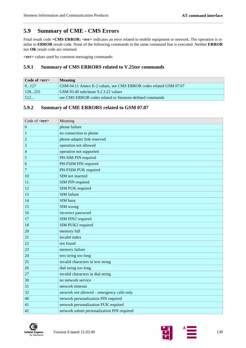
AT command interfaceSiemens Information and Communication Products
5.9 Summary of CME - CMS ErrorsFinal result code +CMS ERROR: <err> indicates an error related to mobile equipment or network. The operation is si-milar to ERROR result code. None of the following commands in the same command line is executed. Neither ERRORnor OK result code are returned.
<err> values used by common messaging commands:
5.9.1 Summary of CMS ERRORS related to V.25ter commands
5.9.2 Summary of CME ERRORS related to GSM 07.07
Code of <err> Meaning0...127 GSM 04.11 Annex E-2 values, see CMS ERROR codes related GSM 07.07
128...255 GSM 03.40 subclause 9.2.3.22 values
512... see CMS ERROR codes related to Siemens-defined commands
Code of <err> Meaning
0 phone failure
1 no connection to phone
2 phone-adapter link reserved
3 operation not allowed
4 operation not supported
5 PH-SIM PIN required
6 PH-FSIM PIN required
7 PH-FSIM PUK required
10 SIM not inserted
11 SIM PIN required
12 SIM PUK required
13 SIM failure
14 SIM busy
15 SIM wrong
16 incorrect password
17 SIM PIN2 required
18 SIM PUK2 required
20 memory full
21 invalid index
22 not found
23 memory failure
24 text string too long
25 invalid characters in text string
26 dial string too long
27 invalid characters in dial string
30 no network service
31 network timeout
32 network not allowed – emergency calls only
40 network personalization PIN required
41 network personalization PUK required
42 network subset personalization PIN required
Version 8 dated 15.03.00 139A
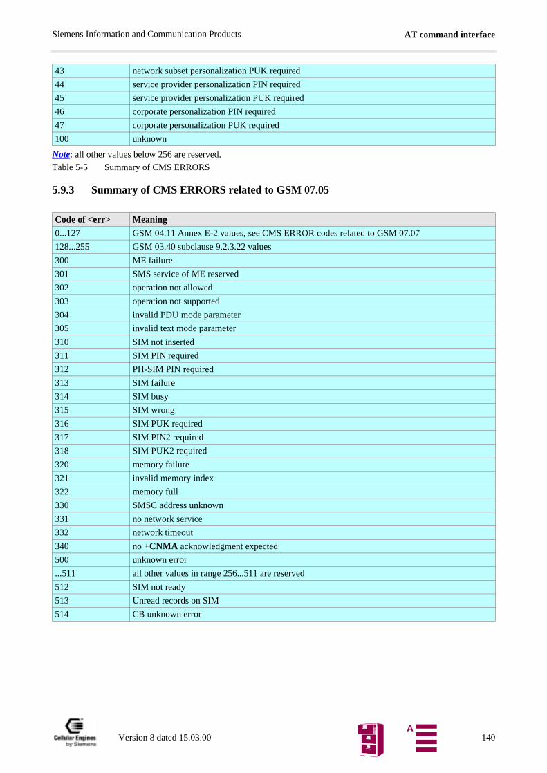
AT command interfaceSiemens Information and Communication Products
Note: all other values below 256 are reserved.
Table 5-5 Summary of CMS ERRORS
5.9.3 Summary of CMS ERRORS related to GSM 07.05
43 network subset personalization PUK required
44 service provider personalization PIN required
45 service provider personalization PUK required
46 corporate personalization PIN required
47 corporate personalization PUK required
100 unknown
Code of <err> Meaning
0...127 GSM 04.11 Annex E-2 values, see CMS ERROR codes related to GSM 07.07
128...255 GSM 03.40 subclause 9.2.3.22 values
300 ME failure
301 SMS service of ME reserved
302 operation not allowed
303 operation not supported
304 invalid PDU mode parameter
305 invalid text mode parameter
310 SIM not inserted
311 SIM PIN required
312 PH-SIM PIN required
313 SIM failure
314 SIM busy
315 SIM wrong
316 SIM PUK required
317 SIM PIN2 required
318 SIM PUK2 required
320 memory failure
321 invalid memory index
322 memory full
330 SMSC address unknown
331 no network service
332 network timeout
340 no +CNMA acknowledgment expected
500 unknown error
...511 all other values in range 256...511 are reserved
512 SIM not ready
513 Unread records on SIM
514 CB unknown error
Version 8 dated 15.03.00 140A
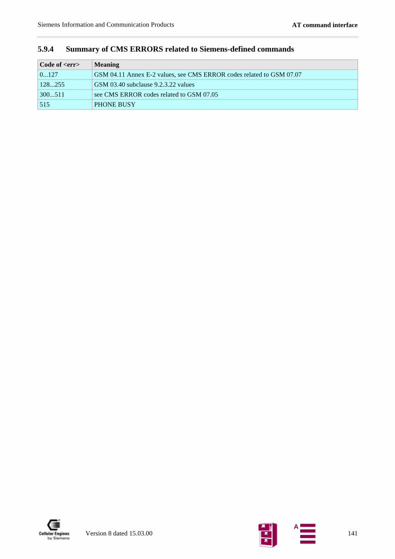
AT command interfaceSiemens Information and Communication Products
5.9.4 Summary of CMS ERRORS related to Siemens-defined commands
:
Code of <err> Meaning
0...127 GSM 04.11 Annex E-2 values, see CMS ERROR codes related to GSM 07.07
128...255 GSM 03.40 subclause 9.2.3.22 values
300...511 see CMS ERROR codes related to GSM 07.05
515 PHONE BUSY
Version 8 dated 15.03.00 141A
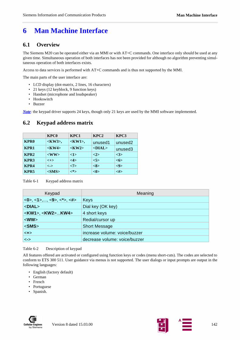
Man Machine InterfaceSiemens Information and Communication Products
lected tout in the
6 Man Machine Interface
6.1 OverviewThe Siemens M20 can be operated either via an MMI or with AT+C commands. One interface only should be used at anygiven time. Simultaneous operation of both interfaces has not been provided for although no algorithm preventing simul-taneous operation of both interfaces exists.
Access to data services is performed with AT+C commands and is thus not supported by the MMI.
The main parts of the user interface are:
• LCD display (dot-matrix, 2 lines, 16 characters)• 21 keys (12 keyblock, 9 function keys) • Handset (microphone and loudspeaker)• Hookswitch• Buzzer
Note: the keypad driver supports 24 keys, though only 21 keys are used by the MMI software implemented.
6.2 Keypad address matrix
Table 6-1 Keypad address matrix
Table 6-2 Description of keypad
All features offered are activated or configured using function keys or codes (menu short-cuts). The codes are seconform to ETS 300 511. User guidance via menus is not supported. The user dialogs or input prompts are outpfollowing languages:
• English (factory default)• German• French• Portuguese• Spanish.
KPC0 KPC1 KPC2 KPC3KPR0 <KW3>, <KW1>, unused1 unused2KPR1 <KW4> <KW2> <DIAL> unused3KPR2 <WW> <1> <2> <3>KPR3 <+> <4> <5> <6>KPR4 <-> <7> <8> <9>KPR5 <SMS> <*> <0> <#>
Keypad Meaning
<0>, <1>,..., <9>, <*>, <#> Keys
<DIAL> Dial key (OK key)
<KW1>, <KW2>...KW4> 4 short keys
<WW> Redial/cursor up
<SMS> Short Message
<+> increase volume: voice/buzzer
<-> decrease volume: voice/buzzer
Version 8 dated 15.03.00 142A
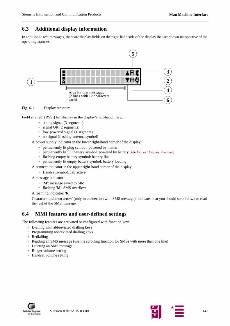
Man Machine InterfaceSiemens Information and Communication Products
o read
6.3 Additional display informationIn addition to test messages, there are display fields on the right-hand side of the display that are shown irrespective of the operating statuses:
Fig. 6-1 Display structure
Field strength (RSSI) bar display in the display’s left-hand margin:
• strong signal (3 segments)• signal OK (2 segments)• low-powered signal (1 segment)• no signal (flashing antenna symbol)
A power supply indicator in the lower right-hand corner of the display:
• permanently lit plug symbol: powered by mains• permanently lit full battery symbol: powered by battery (see Fig. 6-1 Display structure)• flashing empty battery symbol: battery flat• permanently lit empty battery symbol: battery loading
A connect indicator in the upper right-hand corner of the display:
• Handset symbol: call active
A message indicator:
• 'M': message saved to SIM• flashing 'M': SMS overflow
A roaming indicator: 'R'
Character 'up/down arrow' (only in connection with SMS message): indicates that you should scroll down tthe rest of the SMS message.
6.4 MMI features and user-defined settingsThe following features are activated or configured with function keys:
• Dialling with abbreviated dialling keys• Programming abbreviated dialling keys• Redialling• Reading an SMS message (use the scrolling function for SMSs with more than one line)• Deleting an SMS message• Ringer volume setting• Handset volume setting
Area for text messages (2 lines with 12 characters each)
1
5
3
2
4
6
Version 8 dated 15.03.00 143A
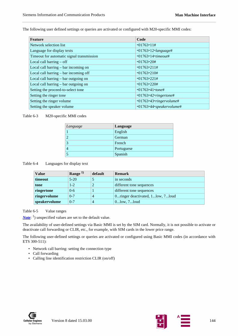
Man Machine InterfaceSiemens Information and Communication Products
The following user defined settings or queries are activated or configured with M20-specific MMI codes:
Table 6-3 M20-specific MMI codes
Table 6-4 Languages for display text
Table 6-5 Value ranges
Note: 1) unspecified values are set to the default value.
The availability of user-defined settings via Basic MMI is set by the SIM card. Normally, it is not possible to activate ordeactivate call forwarding or CLIR, etc., for example, with SIM cards in the lower price range.
The following user-defined settings or queries are activated or configured using Basic MMI codes (in accordance withETS 300-511):
• Network call barring: setting the connection type • Call forwarding • Calling line identification restriction CLIR (on/off)
Feature CodeNetwork selection list *01763*11#
Language for display texts *01763*12*language#
Timeout for automatic signal transmission *01763*14*timeout#
Local call barring – off *01763*20#
Local call barring – bar incoming on *01763*211#
Local call barring – bar incoming off *01763*210#
Local call barring – bar outgoing on *01763*221#
Local call barring – bar outgoing on *01763*220#
Setting the proceed-to-select tone *01763*41*tone#
Setting the ringer tone *01763*42*ringertone#
Setting the ringer volume *01763*43*ringervolume#
Setting the speaker volume *01763*44*speakervolume#
Language Language1 English
2 German
3 French
4 Portuguese
5 Spanish
Value Range 1) default Remarktimeout 5-20 5 in seconds
tone 1-2 2 different tone sequences
ringertone 0-6 1 different tone sequences
ringervolume 0-7 4 0...ringer deactivated, 1...low, 7...loud
speakervolume 0-7 4 0...low, 7...loud
Version 8 dated 15.03.00 144A
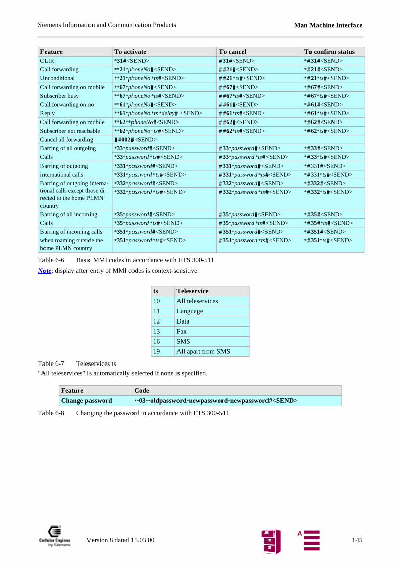
Man Machine InterfaceSiemens Information and Communication Products
Table 6-6 Basic MMI codes in accordance with ETS 300-511
Note: display after entry of MMI codes is context-sensitive.
Table 6-7 Teleservices ts
"All teleservices" is automatically selected if none is specified.
Table 6-8 Changing the password in accordance with ETS 300-511
Feature To activate To cancel To confirm statusCLIR *31#<SEND> #31#<SEND> *#31#<SEND>
Call forwarding
Unconditional
**21*phoneNo#<SEND> ##21#<SEND> *#21#<SEND>
**21*phoneNo *ts#<SEND> ##21*ts#<SEND> *#21*ts#<SEND>
Call forwarding on mobile
Subscriber busy
**67*phoneNo#<SEND> ##67#<SEND> *#67#<SEND>
**67*phoneNo *ts#<SEND> ##67*ts#<SEND> *#67*ts#<SEND>
Call forwarding on no
Reply
**61*phoneNo#<SEND> ##61#<SEND> *#61#<SEND>
**61*phoneNo *ts *delay# <SEND> ##61*ts#<SEND> *#61*ts#<SEND>
Call forwarding on mobile
Subscriber not reachable
**62**phoneNo#<SEND> ##62#<SEND> *#62#<SEND>
**62*phoneNo¬ts#<SEND> ##62*ts#<SEND> *#62*ts#<SEND>
Cancel all forwarding ##002#<SEND>
Barring of all outgoing
Calls
*33*password#<SEND> #33*password#<SEND> *#33#<SEND>
*33*password *ts#<SEND> #33*password *ts#<SEND> *#33*ts#<SEND>
Barring of outgoing
international calls
*331*password#<SEND> #331*password#<SEND> *#331#<SEND>
*331*password *ts#<SEND> #331*password *ts#<SEND> *#331*ts#<SEND>
Barring of outgoing interna-tional calls except those di-rected to the home PLMN country
*332*password#<SEND> #332*password#<SEND> *#332#<SEND>
*332*password *ts#<SEND> #332*password *ts#<SEND> *#332*ts#<SEND>
Barring of all incoming
Calls
*35*password#<SEND> #35*password#<SEND> *#35#<SEND>
*35*password *ts#<SEND> #35*password *ts#<SEND> *#35#*ts#<SEND>
Barring of incoming calls
when roaming outside the home PLMN country
*351*password#<SEND> #351*password#<SEND> *#351#<SEND>
*351*password *ts#<SEND> #351*password *ts#<SEND> *#351*ts#<SEND>
ts Teleservice
10 All teleservices
11 Language
12 Data
13 Fax
16 SMS
19 All apart from SMS
Feature Code
Change password **03**oldpassword*newpassword*newpassword#<SEND>
Version 8 dated 15.03.00 145A

Man Machine InterfaceSiemens Information and Communication Products
6.5 MMI functionsLogical display messages are written in square brackets:e. g: [Network operator] appears as ‘A max.’, for example, on the display.
Key messages are written in angle brackets: e.g. <DIAL>.
6.5.1 Putting into service
6.5.2 Handset answer functions – incoming seizure
The user accepts an incoming call by off-hook (lifting the handset).
Incoming call with off-hook handset:
An incoming call is rejected in state off-hook. The calling party hears the busy tone applied by the PLMN.
Clear down before answer
The calling party deactivated CLIR
Event Display text: 1st line
Display text: 2nd line
Remark
SIM not inserted Insert SIMSIM inserted: searching or novalid PLMN
SearchingNetwork
Power-on, no valid PLMN signal received, SIMinserted
PIN input
(dialling keys)
Enter Pin:****
PIN entry shown as ‘*’
PLMN signal [Network operator] Idle display
Event Display text: 1st line
Display text: 2nd line
Remark
Call Incoming Call
Off-hook Call Active
Event Display text: 1st line
Display text: 2nd line
Remark
Call Incoming CallDisconnect Call miss Calling party clears down the call
Event Display text: 1st line
Display text: 2nd line
Remark
Call Incoming Call[Dial]
Off-hook Call Active[Dial]
Version 8 dated 15.03.00 146A
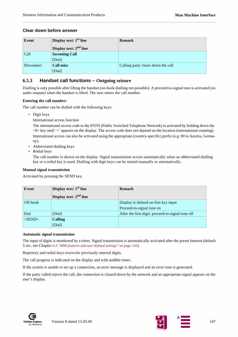
Man Machine InterfaceSiemens Information and Communication Products
wn the aming).
Germa-
ialling
(default
Clear down before answer
6.5.3 Handset call functions – Outgoing seizure
Dialling is only possible after lifting the handset (on-hook dialling not possible). A proceed-to-signal tone is activated (onaudio outputs) when the handset is lifted. The user enters the call number.
Entering the call number:
The call number can be dialled with the following keys:
• Digit keys
International access function
The international access code to the PSTN (Public Switched Telephone Network) is activated by holding do<0> key until ‘+’ appears on the display. The access code does not depend on the location (international ro
International access can also be activated using the appropriate (country-specific) prefix (e.g. 00 in Austria, ny).
• Abbreviated dialling keys• Redial keys
The call number is shown on the display. Signal transmission occurs automatically when an abbreviated dkey or a redial key is used. Dialling with digit keys can be started manually or automatically.
Manual signal transmission
Activated by pressing the SEND key.
Automatic signal transmission
The input of digits is monitored by a timer. Signal transmission is automatically activated after the preset timeout 5 sec, see Chapter 6.4 “MMI features and user-defined settings” on page 143).
Repertory and redial keys overwrite previously entered digits.
The call progress is indicated on the display and with audible tones.
If the system is unable to set up a connection, an error message is displayed and an error tone is generated.
If the party called rejects the call, the connection is cleared down by the network and an appropriate signal appears on theuser’s display.
Event Display text: 1st line
Display text: 2nd line
Remark
Call Incoming Call[Dial]
Disconnect Call miss[Dial]
Calling party clears down the call
Event Display text: 1st line
Display text: 2nd line
Remark
Off-hook Display is deleted on first key input
Proceed-to-signal tone on
Dial [Dial] After the first digit: proceed-to-signal tone off
<SEND> Calling[Dial]
Version 8 dated 15.03.00 147A
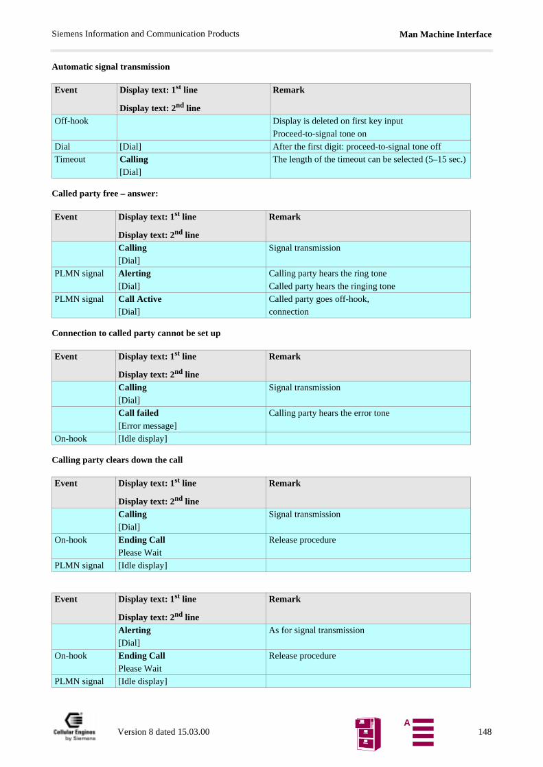
Man Machine InterfaceSiemens Information and Communication Products
Automatic signal transmission
Called party free – answer:
Connection to called party cannot be set up
Calling party clears down the call
Event Display text: 1st line
Display text: 2nd line
Remark
Off-hook Display is deleted on first key input
Proceed-to-signal tone on
Dial [Dial] After the first digit: proceed-to-signal tone off
Timeout Calling[Dial]
The length of the timeout can be selected (5–15 sec.)
Event Display text: 1st line
Display text: 2nd line
Remark
Calling[Dial]
Signal transmission
PLMN signal Alerting[Dial]
Calling party hears the ring tone
Called party hears the ringing tone
PLMN signal Call Active[Dial]
Called party goes off-hook,
connection
Event Display text: 1st line
Display text: 2nd line
Remark
Calling[Dial]
Signal transmission
Call failed[Error message]
Calling party hears the error tone
On-hook [Idle display]
Event Display text: 1st line
Display text: 2nd line
Remark
Calling[Dial]
Signal transmission
On-hook Ending CallPlease Wait
Release procedure
PLMN signal [Idle display]
Event Display text: 1st line
Display text: 2nd line
Remark
Alerting[Dial]
As for signal transmission
On-hook Ending CallPlease Wait
Release procedure
PLMN signal [Idle display]
Version 8 dated 15.03.00 148A
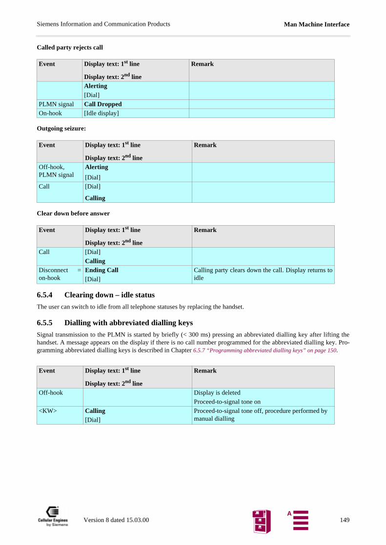
Man Machine InterfaceSiemens Information and Communication Products
Called party rejects call
Outgoing seizure:
Clear down before answer
6.5.4 Clearing down – idle status
The user can switch to idle from all telephone statuses by replacing the handset.
6.5.5 Dialling with abbreviated dialling keys
Signal transmission to the PLMN is started by briefly (< 300 ms) pressing an abbreviated dialling key after lifting thehandset. A message appears on the display if there is no call number programmed for the abbreviated dialling key. Pro-gramming abbreviated dialling keys is described in Chapter 6.5.7 “Programming abbreviated dialling keys” on page 150.
Event Display text: 1st line
Display text: 2nd line
Remark
Alerting[Dial]
PLMN signal Call DroppedOn-hook [Idle display]
Event Display text: 1st line
Display text: 2nd line
Remark
Off-hook,PLMN signal
Alerting
[Dial]
Call [Dial]
Calling
Event Display text: 1st line
Display text: 2nd line
Remark
Call [Dial]
CallingDisconnect =on-hook
Ending Call[Dial]
Calling party clears down the call. Display returns toidle
Event Display text: 1st line
Display text: 2nd line
Remark
Off-hook Display is deleted
Proceed-to-signal tone on
<KW> Calling[Dial]
Proceed-to-signal tone off, procedure performed by manual dialling
Version 8 dated 15.03.00 149A
Man Machine InterfaceSiemens Information and Communication Products
nd). Thelay after
re (see
des. Toeature
6.5.6 Checking abbreviated dialling keys
An abbreviated dialling key can be checked in the following call processing terminal statuses:
• idle status (handset is on-hook)• after off-hook • when a call is in progress
The abbreviated dialling key must be held down until the saved call number appears on the display (approx.1 secomessage "No number" is displayed if there is no call number saved. The display switches back to the original disp30 seconds (or by going on-hook).
6.5.7 Programming abbreviated dialling keys
Abbreviated dialling keys can be overwritten (by keypad entry) while they are displayed in the checking proceduChapter 6.5.6 “Checking abbreviated dialling keys” on page 150).
6.5.8 Redial
The last call number dialled is shown on the display and signal transmission to the PLMN is started by pressing the redialkey after going off-hook. Call numbers are transferred to the redial memory during signal transmission.
6.5.9 Network call barring
The PLMN offers the user the option of barring special connections. This is activated by the user with a code and password(see Chapter 6.4 “MMI features and user-defined settings” on page 143). The following connections can be barred:
• all outgoing connections• all outgoing international connections• all outgoing international connections that are not directed to the home PLMN country• all incoming connections• all incoming connections in the case of roaming outside the home PLMN country
6.5.10 Local call barring
As in the case of PLMN, special connections can be barred in the terminal. This is activated by the user with codistinguish this feature from network call barring, no signalling information is sent to the PLMN. As a result, this fcan also be used when no connection to the PLMN can be set up.
The following connections can be barred:
• all outgoing connections• all incoming connections
Note: local call barring features are not recognised by the network. They are locally set in the terminal.
Event Display text: 1st line
Display text: 2nd line
Remark
Off-hook Display is deleted
Proceed-to-signal tone on
<WW> Calling[Dial]
Proceed-to-signal tone off, procedure performed by manual dialling
Version 8 dated 15.03.00 150A
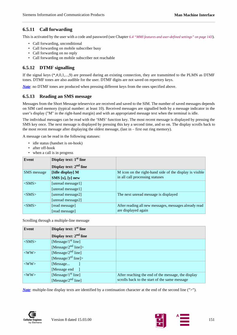
Man Machine InterfaceSiemens Information and Communication Products
DTMF
es dependstor in the
ssing thells back to
6.5.11 Call forwarding
This is activated by the user with a code and password (see Chapter 6.4 “MMI features and user-defined settings” on page 143).
• Call forwarding, unconditional• Call forwarding on mobile subscriber busy• Call forwarding on no reply• Call forwarding on mobile subscriber not reachable
6.5.12 DTMF signalling
If the signal keys (*,#,0,1,...,9) are pressed during an existing connection, they are transmitted to the PLMN astones. DTMF tones are also audible for the user. DTMF digits are not saved on repertory keys.
Note: no DTMF tones are produced when pressing different keys from the ones specified above.
6.5.13 Reading an SMS message
Messages from the Short Message teleservice are received and saved to the SIM. The number of saved messagon SIM card memory (typical number: at least 10). Received messages are signalled both by a message indicauser’s display ("M" in the right-hand margin) and with an appropriated message text when the terminal is idle.
The individual messages can be read with the ‘SMS’ function key. The most recent message is displayed by preSMS key once. The next message is displayed by pressing this key a second time, and so on. The display scrothe most recent message after displaying the oldest message, (last in – first out ring memory).
A message can be read in the following statuses:
• idle status (handset is on-hook)• after off-hook• when a call is in progress
Scrolling through a multiple-line message
Note: multiple-line display texts are identified by a continuation character at the end of the second line (”>”).
Event Display text: 1st line
Display text: 2nd lineSMS message [Idle display] M
SMS [x], [y] newM icon on the right-hand side of the display is visiblein all call processing statuses
<SMS> [unread message1]
[unread message1]<SMS> [unread message2]
[unread message2]
The next unread message is displayed
<SMS> [read message]
[read message]
After reading all new messages, messages already read are displayed again
Event Display text: 1st line
Display text: 2nd line<SMS> [Message/1st line]
[Message/2nd line]><WW> [Message/2nd line]
[Message/3rd line]><WW> [Message... ]
[Message end ]<WW> [Message/1st line]
[Message/2nd line]
After reaching the end of the message, the display scrolls back to the start of the same message
Version 8 dated 15.03.00 151A
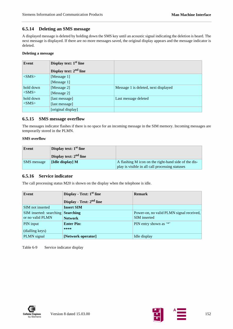
Man Machine InterfaceSiemens Information and Communication Products
6.5.14 Deleting an SMS message
A displayed message is deleted by holding down the SMS key until an acoustic signal indicating the deletion is heard. Thenext message is displayed. If there are no more messages saved, the original display appears and the message indicator isdeleted.
Deleting a message
6.5.15 SMS message overflow
The messages indicator flashes if there is no space for an incoming message in the SIM memory. Incoming messages aretemporarily stored in the PLMN.
SMS overflow
6.5.16 Service indicator
The call processing status M20 is shown on the display when the telephone is idle.
Table 6-9 Service indicator display
Event Display text: 1st line
Display text: 2nd line<SMS> [Message 1]
[Message 1]
hold down <SMS>
[Message 2]
[Message 2]
Message 1 is deleted, next displayed
hold down <SMS>
[last message]
[last message]
Last message deleted
[original display]
Event Display text: 1st line
Display text: 2nd lineSMS message [Idle display] M A flashing M icon on the right-hand side of the dis-
play is visible in all call processing statuses
Event Display - Text: 1st line
Display - Text: 2nd line
Remark
SIM not inserted Insert SIMSIM inserted: searchingor no valid PLMN
SearchingNetwork
Power-on, no valid PLMN signal received,SIM inserted
PIN input
(dialling keys)
Enter Pin:****
PIN entry shown as ‘*’
PLMN signal [Network operator] Idle display
Version 8 dated 15.03.00 152A
Man Machine InterfaceSiemens Information and Communication Products
ey. Thishe default
lume isn
ware de-
o Chapter
6.5.17 Network selection
Automatic selection (default setting):
A network is automatically selected on insertion of the SIM card and when the M20 is activated.
Manual selection:
All possible network operators can be shown on the display by using the code *01763*11#. The keys <+> and <-> (or<Cursor up>) are used to scroll up and down the list. The network operator is selected with the <send> key. The user isinformed via the display (error message) if he/she cannot log on to this PLMN. The call processing status M20 is displayedwhen the telephone is idle (service indicator).
6.5.18 SIM lock
If the SIM card is protected by a 4-digit PIN, this must be entered via the keyboard each time after inserting the card. Emer-gency calls can be made without the SIM card or without entering the PIN.
i.e. the user must enter the PIN at the terminal in the following situations:
• after switching on the power (i.e. when power returns after a power failure)• after inserting a SIM card
6.5.19 RSSI
The field strength is indicated by a bar on the left-hand side of the display.
Four different levels can be shown:
• strong signal (3 segments)• signal OK (2 segments)• low powered signal (1 segment)• no signal (flashing antenna symbol)
6.5.20 Ringer volume setting
The idle telephone (handset is on hook) can be switched to programming mode by holding down the <+> or <-> kgenerates a ring tone. Every time <+> or <-> is pressed, the volume is increased or decreased in stages (for tvalue and value range see Value ranges). The setting is stored until the SIM card is reset.
6.5.21 Language volume setting
The volume can be changed by pressing <+> or <-> during a call. Every time <+> or <-> is pressed, the voincreased or decreased in stages (for default value and value range see Value ranges). The setting is stored for the duratioof the call.
6.6 Power supply indicatorIn the event of a power failure, power supply can be switched to battery operation by means of an external hardvice.
The type of power supply and the battery status can be checked on the ‘supply status’ hardware indicator. See als4.3.9 “Power supply indicator” on page 24.
Version 8 dated 15.03.00 153A
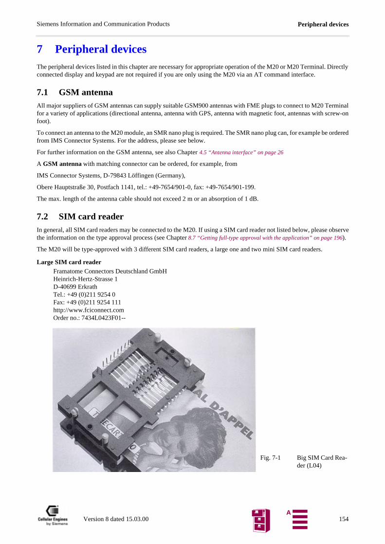
Peripheral devicesSiemens Information and Communication Products
observe
7 Peripheral devicesThe peripheral devices listed in this chapter are necessary for appropriate operation of the M20 or M20 Terminal. Directlyconnected display and keypad are not required if you are only using the M20 via an AT command interface.
7.1 GSM antennaAll major suppliers of GSM antennas can supply suitable GSM900 antennas with FME plugs to connect to M20 Terminalfor a variety of applications (directional antenna, antenna with GPS, antenna with magnetic foot, antennas with screw-onfoot).
To connect an antenna to the M20 module, an SMR nano plug is required. The SMR nano plug can, for example be orderedfrom IMS Connector Systems. For the address, please see below.
For further information on the GSM antenna, see also Chapter 4.5 “Antenna interface” on page 26
A GSM antenna with matching connector can be ordered, for example, from
IMS Connector Systems, D-79843 Löffingen (Germany),
Obere Hauptstraße 30, Postfach 1141, tel.: +49-7654/901-0, fax: +49-7654/901-199.
The max. length of the antenna cable should not exceed 2 m or an absorption of 1 dB.
7.2 SIM card readerIn general, all SIM card readers may be connected to the M20. If using a SIM card reader not listed below, pleasethe information on the type approval process (see Chapter 8.7 “Getting full-type approval with the application” on page 196).
The M20 will be type-approved with 3 different SIM card readers, a large one and two mini SIM card readers.
Large SIM card readerFramatome Connectors Deutschland GmbHHeinrich-Hertz-Strasse 1D-40699 ErkrathTel.: +49 (0)211 9254 0Fax: +49 (0)211 9254 111http://www.fciconnect.comOrder no.: 7434L0423F01--
Fig. 7-1 Big SIM Card Rea-der (L04)
Version 8 dated 15.03.00 154A
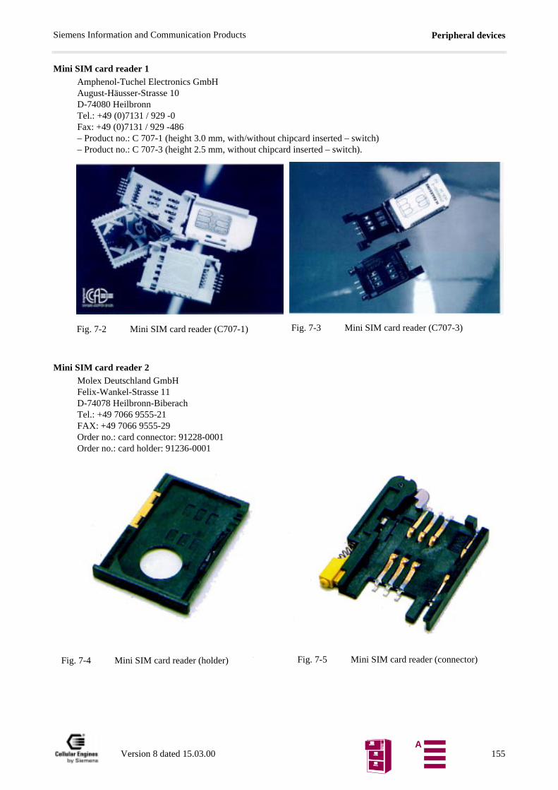
Peripheral devicesSiemens Information and Communication Products
Mini SIM card reader 1 Amphenol-Tuchel Electronics GmbHAugust-Häusser-Strasse 10D-74080 HeilbronnTel.: +49 (0)7131 / 929 -0Fax: +49 (0)7131 / 929 -486– Product no.: C 707-1 (height 3.0 mm, with/without chipcard inserted – switch)– Product no.: C 707-3 (height 2.5 mm, without chipcard inserted – switch).
Mini SIM card reader 2Molex Deutschland GmbHFelix-Wankel-Strasse 11D-74078 Heilbronn-BiberachTel.: +49 7066 9555-21FAX: +49 7066 9555-29Order no.: card connector: 91228-0001Order no.: card holder: 91236-0001
Fig. 7-2 Mini SIM card reader (C707-1) Fig. 7-3 Mini SIM card reader (C707-3)
Fig. 7-4 Mini SIM card reader (holder) Fig. 7-5 Mini SIM card reader (connector)
Version 8 dated 15.03.00
155A
Peripheral devicesSiemens Information and Communication Products
ach
ation is
iven in
7.3 SIM cards• The following services can only be implemented if they are enabled for the subscriber (multi-numbering: e
of the services has its own calling number):
1) Calling number for speech and SMS
2) Calling number for fax (and SMS)
3) Calling number for 9600 Bit/s data transfer (and SMS)
4) Calling number for 4800 Bit/s data transfer (and SMS)
5) Calling number for 2400 Bit/s data transfer (and SMS)
3 V SIM cards are available from different network operators and service providers.
7.4 HandsetDepending on the type of application, handsets can be ordered from common handset manufacturers. Informavailable from the M20 distributor.
If using one of the handset types listed below AND implementing the audio reference circuit for that handsets gChapter 8.8 “Application examples and reference circuits” on page 198, no additional delta type approval is necessary.
If using handsets not listed below, please observe the information regarding the type approval process (see Chapter 8.7“Getting full-type approval with the application” on page 196).
Handset 1: (not shown)Handset Siemens Gigaset
Please contact your local M20 distributor
Note: for technical data on speaker and microphone, see Chapter 4.4 “Audio interface” on page 25.
Version 8 dated 15.03.00 156A
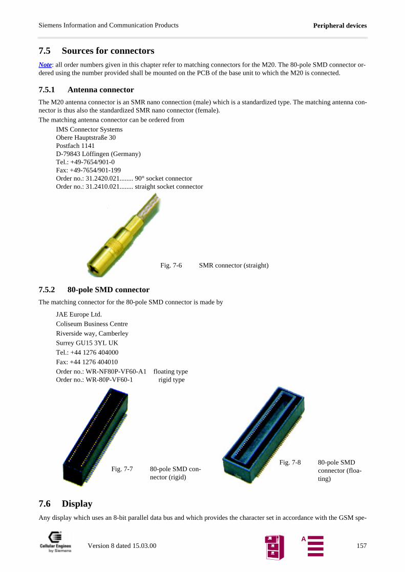
Peripheral devicesSiemens Information and Communication Products
SM spe-
7.5 Sources for connectorsNote: all order numbers given in this chapter refer to matching connectors for the M20. The 80-pole SMD connector or-dered using the number provided shall be mounted on the PCB of the base unit to which the M20 is connected.
7.5.1 Antenna connector
The M20 antenna connector is an SMR nano connection (male) which is a standardized type. The matching antenna con-nector is thus also the standardized SMR nano connector (female).
The matching antenna connector can be ordered from
IMS Connector SystemsObere Hauptstraße 30Postfach 1141D-79843 Löffingen (Germany)Tel.: +49-7654/901-0Fax: +49-7654/901-199Order no.: 31.2420.021........ 90° socket connector Order no.: 31.2410.021........ straight socket connector
7.5.2 80-pole SMD connector
The matching connector for the 80-pole SMD connector is made by
JAE Europe Ltd.
Coliseum Business Centre
Riverside way, Camberley
Surrey GU15 3YL UK
Tel.: +44 1276 404000
Fax: +44 1276 404010
Order no.: WR-NF80P-VF60-A1 floating typeOrder no.: WR-80P-VF60-1 rigid type
7.6 DisplayAny display which uses an 8-bit parallel data bus and which provides the character set in accordance with the G
Fig. 7-6 SMR connector (straight)
Fig. 7-7 80-pole SMD con-nector (rigid)
Fig. 7-8 80-pole SMD connector (floa-ting)
Versio
n 8 dated 15.03.00 157A
Peripheral devicesSiemens Information and Communication Products
cification (GSM 0338(EPS) 300-628) can be used. In addition, the timing requirements and electrical specifications out-lined in Chapter shall be respected. See also “Display”.
7.7 KeypadAny keypad which fulfils the requirements outlined in Chapter 4.3.4 “Keypad” on page 20 can be used.
Version 8 dated 15.03.00 158A
Application notesSiemens Information and Communication Products
fi-
ach
he
nd
ug.
econd
8 Application notes1) The Cellular Engine M20 may only be used in approved configurations or with accessories (SIM card reader, handset)
that have been explicitly approved. Information about approved configurations and accessories that have been appro-ved for use with the M20 is provided in this document. This information is also available in the appendix to the EC TYPE EXAMINATION CERTIFICATE or from your local distributor.
2) The CE mark on the Siemens M20 with GSM-IMEI must be visible from the outside without the use of any tools, even if the M20 is integrated and/or built into an application (visibility through cooling slits is sufficient). Alterna-tively, an additional label can be placed on the outside of the application or if there is not enough room, it can be included in the operating manual with the wording "This application uses integrated GSM Terminal Equipment with the following registration: CE xxxx, IMEI xxxx."
3) An earthed wristband should be worn when handling the M20/M20 terminal components to protect against electrosta-tic charge. Avoid touching open contacts to prevent injury by electrostatic discharge.
8.1 General notes• A warning symbol from TÜV (German Technical Inspectorate) should be applied to the application’s identi
cation plate, advising the user to read the instruction manual before powering up the application.
• The following services can only be implemented if they are enabled for the subscriber. Multi-numbering: eof the services has its own calling number.
1) Calling number for speech and SMS
2) Calling number for 4800 Bit/s data transfer (and SMS)
3) Calling number for 2400 Bit/s data transfer (and SMS)
• 3 V SIM cards are available from different network operators and service providers.
• A sticker with the IMEI number is supplied with the M20 to be applied on the outside of the application. In tevent of M20 module service, a new sticker with the new IMEI number will be supplied.
• Two stickers with the logo “Cellular Engines by Siemens” are supplied with each M20 (transparency/black atransparency/yellow 24 mm x 24 mm). See below in the lower left corner.
• SIM cards should only be inserted or removed when the M20 is not supplied with power.
8.2 Getting started & InstallationUsing Hyperterminal or Procomm Plus for controlling the M20T:
8.2.1 Connecting the M20T
1) M20 Application, M20 Terminal or M20 D-Box2) SIM card (activated, M20/M20 Terminal can only be activated by 3V SIM cards)3) 9-pin serial cable for connection between PC an e.g. M20 Terminal4) For speech transmission: Handset: speaker and microphone5) Antenna cable with antenna and fitting connector for connection with M20 Terminal´s FME female antenna pl6) GSM Antenna7) Power supply with ignition circuit, Pin 4 of the 6 pole Western Plug can be switched to >3V for minimum 1 s(with the M20T use supply voltage for ignition).
See also following fig. “Example circuit for IGNITION” for details.
8.2.2 Example circuit for IGNITION
The Ignition signal is used to start the M20. Unlike the M1 the Ignition on the M20 can be activated simultaneously withthe Power connection. For switching off the M20 with AT^SMSO ignition must be returned to low state!
Version 8 dated 15.03.00 159A
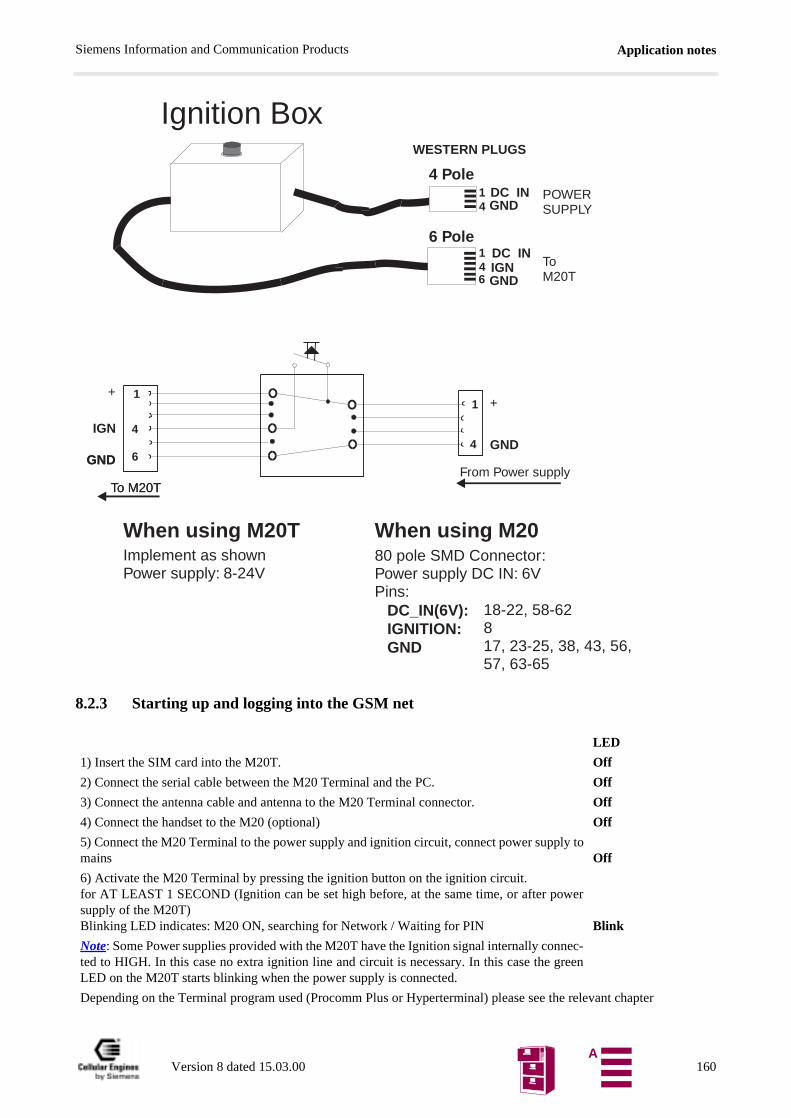
Application notesSiemens Information and Communication Products
8.2.3 Starting up and logging into the GSM net
LED
1) Insert the SIM card into the M20T. Off
2) Connect the serial cable between the M20 Terminal and the PC. Off
3) Connect the antenna cable and antenna to the M20 Terminal connector. Off
4) Connect the handset to the M20 (optional) Off
5) Connect the M20 Terminal to the power supply and ignition circuit, connect power supply tomains Off
6) Activate the M20 Terminal by pressing the ignition button on the ignition circuit.for AT LEAST 1 SECOND (Ignition can be set high before, at the same time, or after powersupply of the M20T)Blinking LED indicates: M20 ON, searching for Network / Waiting for PIN Blink
Note: Some Power supplies provided with the M20T have the Ignition signal internally connec-ted to HIGH. In this case no extra ignition line and circuit is necessary. In this case the greenLED on the M20T starts blinking when the power supply is connected.
Depending on the Terminal program used (Procomm Plus or Hyperterminal) please see the relevant chapter
Ignition Box
When using M2080 pole SMD Connector:Power supply DC IN: 6VPins:
DC_IN(6V):IGNITION:GND
18-22, 58-62817, 23-25, 38, 43, 56,57, 63-65
When using M20TImplement as shownPower supply: 8-24V
To M20T
GND
IGN
+ 1
4
6
To M20TFrom Power supply
GNDGND4
1
WESTERN PLUGS
+
IGN146
ToM20TGND
DC IN
POWERSUPPLYGND
DC IN14
4 Pole
6 Pole
Version 8 dated 15.03.00 160A
Application notesSiemens Information and Communication Products
8.2.4 Hyperterminal: Setup (M20.ht)
Using the Hyperterminal program: (Standard Windows application)
Copy the configuration file M20.ht (included on the CD-ROM) to the hyperterminal directory (usually: c:\ ..... startmenu\programs\accessories\hyperterminal) up the M20T
To start:START - programs - accessories - hyperterminal - "m20.ht"
Once the Hyperterminal window is opened and the keypresses are echoed, the M20 is ready for further commands.
To register the M20T into the net use: Type: AT+CPIN="<four digit PIN code>"
8.2.5 Procomm Plus: Setup and activation
Getting started and basic scripts for voice and data calls and SMS (text mode).
8.2.5.1 Procomm Plus setup files:
(From the included CD-ROM copy the following files to the subdirectories of Procomm Plus on your PC)
Copy to directory:..... procomm Plus/Connect_first.dirConnect_first.ext
Copy to directory:.....procomm Plus/aspectsstart.was configuration informationdata_ic.was Data incomingdata_og.was Data outgoingsms_ic.was SMS incomingsms_og.was SMS outgoingvoice_ic.was Voice incomingvoice_og.was Voice outgoing
7) Enter the Pin number with the command AT+CPIN="xxxx", unless AT^SFLC (facility lockfor PIN code has been set. In this case the log-in to the GSM network will start automaticallyafter the ignition phase is completed Blink
8) Once the M20T is logged into the net the LED is on. (usually about 5 sec or longer dependingon the network availability.)
Lit
Version 8 dated 15.03.00 161A
Application notesSiemens Information and Communication Products
8.2.5.2 Start Procomm Plus
(START - programs - Procomm - Procomm Plus) To activate configuration file:
Activate "M20_start" by double-clicking in the data - pulldown menu.
M20T connected and ON (see chapter 3.3.1)
This automatically configures the system to connect to the M20T via COM1.
The script "Start" automatically is activated and a sequence of commands is executed giving information about the settingsof the M20.
Enter the PIN code in the pop up window.
Once the M20T is booked into the net, -- +creg:1 - network information is displayed
M20T Ready.
NOTE: If the script is unable to process a command, there is a 15 second internal timeout after which the next commandis automatically sent to the M20.
NOTE: If the script does not operate correctly it can be stopped/exited and restarted with the Button .
The Procomm Plus scripts for Data, Voice and SMS incoming and outgoing can be activated from the script window.
Using the script control button a script can be started and stopped.
8.2.6 Setting parameters
8.2.6.1 Enter PIN1
8.2.6.2 Enter PUK1
8.2.6.3 Change PIN1
at+cpin? Ask which PIN is required
+CPIN: SIM PIN SIM PIN is needed
OK
at^spic Display PIN counter
^SPIC: 3 3 attempts still available
OK
at+cpin="xxxx" Enter PIN
OK
at+cpin?
+CPIN: SIM PUK SIM PUK is required
OK
at^spic
^SPIC: 10 10 attempts still available for SIM PUK
OK
at+cpin="xxxxxxxx","xxxx" Enter PUK and new PIN
OK
at+cpin?
+CPIN: READY SIM is ready
OK
Version 8 dated 15.03.00 162A
Application notesSiemens Information and Communication Products
8.2.6.4 Lock/unlock PIN1
8.2.6.5 Signal Quality
8.2.6.6 Set all current parameters to manufacturer default
8.2.6.7 Store current parameter to user defined profile
8.2.6.8 Set all current parameters to user defined profile
at+cpwd="SC","xxxx","xxxx" ”SC” SIM PIN is changed
”8418” old PIN
”8888” new PIN
OK
at+clck="SC",2 Query PIN1 lock/unlock status
+CLCK: 1 Status is ”on” (locked)
OK
at+clck="SC",0,"xxxx" Unlock PIN1
OK
at+clck="SC",2 Query status
+CLCK: 0 Status is ”off” (unlocked)
OK
at+clck="SC",1,"xxxx" Lock PIN1
OK
at+clck="SC",2 Query status
+CLCK: 1 Status is ”on” (locked)
OK
at+csq Query signal quality
+CSQ: 23,0 Signal quality
OK
at&f Set to manufacturer default
OK
at&w Store current parameter to default profile
OK
at&w0 Store current parameter to profile no. 0
OK
atz Set to user default profile
OK
atz0 Set to user default profile no. 0
OK
Version 8 dated 15.03.00 163A
Application notesSiemens Information and Communication Products
ow”
ta-
8.2.6.9 Display current configuration
8.2.7 Phonebook handling
8.2.7.1 Select phonebook
at&v Display current configuration
ACTIVE PROFILE:E1 L0 M0 Q0 V1 X4;S0:0 S2:43 S3:13 S4:10 S5:8 S6:2 S7:60 S8:2 S10:15 S12:10 S13:60 S1:0+CBST: 7,0,1+CRLP: 61,61,48,6,2,5+CRC: 0+CR: 0+FCLASS: 0+IFC: 2,2+ICF: 3,3+DR: 0+CMGF: 1+CSDH: 0+CNMI: 2,1,0,0,0+ILRR: 0+IPR: 19200+DS: 3,0,512,6+CMEE: 0^SMGO: 0+CSMS: 0^SACM: 0^SCKS: 0
+CREG: 0+CCUG: 0,0,0+CLIP: 0+COLP: 0+CCWA: 0+CAOC: 1+CLIR: 0+COPS: 0
S0-S13 display and calling parameters
“AT+CBST Select Bearer Service Type”
“AT+CRLP Select radio link protocol param. for orig. non-transparent data call”
“AT+CRC Set Cellular Result Codes for incoming call indication”
“AT+CR Service reporting control”
“AT+FCLASS Fax: select, read or test service class”
“AT+IFC Set TE-TA local data flow control”
“AT+ICF Set TE-TA control character framing”
“AT+DR V.42bis data compression reporting control”
“AT+CMGF Select SMS message format”
“AT+CSDH Show SMS text mode parameters”
“AT+CNMI New SMS message indications”
“AT+ILRR Set TE-TA local rate reporting mode”
“AT+IPR Set fixed local rate”
“AT+DS V.42bis data compression control”
“AT+CMEE Report mobile equipment error”
“AT^SMGO Set or query SMS overflow presentation mode or query SMS overfl
“AT+CSMS Select Message Service”
“AT^SACM Advice of charge and query of ACM and ACMmax”
“AT^SCKS Set SIM connection presentation mode and query SIM connection stus”
“AT+CREG Network registration”
“AT+CCUG Closed user group control”
“AT+CLIP Calling line identification presentation”
“AT+COLP Connected line identification presentation”
“AT+CCWA Call waiting control”
“AT+CAOC Advice of Charge information”
“AT+CLIR Calling line identification restriction”
“AT+COPS Operator selection”
OK
at+cpbs=? Ask for a list of supported storages
+CPBS: "SM", "FD", "LD", "RC", "ON", "ME", "MC", "MT"
List of supported storages:
SIM ph.b., fixdialling-phonebook, last-dialling-phonebook, own phone-book
OK
at+cpbs="SM" Select SIM phonebook
OK
at+cpbs? Ask for current selected phonebook memory
+CPBS: "SM” Current select is ”SM”
Version 8 dated 15.03.00 164A
Application notesSiemens Information and Communication Products
8.2.7.2 Read phonebook entry
8.2.7.3 Select phonebook memory storage
8.2.7.4 Write phonebook entry
OK
NOTE: it is useful to check which book is used before reading(see:1.4)
at+cpbr=?
+CPBR: (0-2),40, 30 (ON is selected) index: 0-2;
length of no.: 40; length of name: 30
OK
NOTE: the number of phone numbers that can be stored dependson your SIM card
+CPBR: (0-125),40,30 if SM phonebook is selected
+CPBR: (0-5),40,30 ...FD...
+CPBR: (0-8),40,30 ...LD...
at+cpbr=number1[,number2] reads the entries of the current phonebook entries stored betweennumber 1 and number 2
You can only read the entry in position number 1 if you do notenter number 2
+CPBR: 61,...+CPBR: 62, ”+436642254766”,145,”Susanne”
+CPBR: 63,”01170735397”,129,””+CPBR: 64,...
The international number for Susanne is stored (SM selected) inposition 62 of this memory
This is a national number, no name has been entered
OK
at+cpbs=? Ask for list of supported storages
+CPBS: ("SM","FD","LD","RC","ON","ME","MC","MT")
List of supported storages
OK
at+cpbs="SM" Select SIM phonebook
OK
at+cpbs="FD" Select SIM fixdialling-phonebook
OK
at+cpbs="ON" Select SIM (or ME) own numbers (MSISSDNs) list
OK
at+cpbs? Ask for current selected phonebook memory
+CPBS: "ON" Current select is ”ON”
OK
at+cpbw=? Ask for location range supported by the current storage
Version 8 dated 15.03.00 165A
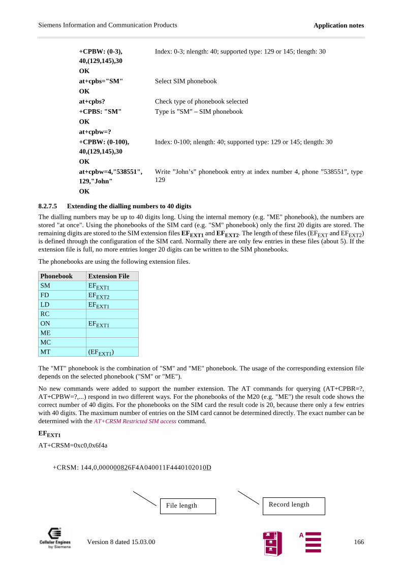
Application notesSiemens Information and Communication Products
pe
8.2.7.5 Extending the dialling numbers to 40 digits
The dialling numbers may be up to 40 digits long. Using the internal memory (e.g. "ME" phonebook), the numbers arestored "at once". Using the phonebooks of the SIM card (e.g. "SM" phonebook) only the first 20 digits are stored. Theremaining digits are stored to the SIM extension files EFEXT1 and EFEXT2. The length of these files (EFEXT and EFEXT2)is defined through the configuration of the SIM card. Normally there are only few entries in these files (about 5). If theextension file is full, no more entries longer 20 digits can be written to the SIM phonebooks.
The phonebooks are using the following extension files.
The "MT" phonebook is the combination of "SM" and "ME" phonebook. The usage of the corresponding extension filedepends on the selected phonebook ("SM" or "ME").
No new commands were added to support the number extension. The AT commands for querying (AT+CPBR=?,AT+CPBW=?,...) respond in two different ways. For the phonebooks of the M20 (e.g. "ME") the result code shows thecorrect number of 40 digits. For the phonebooks on the SIM card the result code is 20, because there only a few entrieswith 40 digits. The maximum number of entries on the SIM card cannot be determined directly. The exact number can bedetermined with the AT+CRSM Restricted SIM access command.
EFEXT1
AT+CRSM=0xc0,0x6f4a
+CPBW: (0-3),40,(129,145),30
Index: 0-3; nlength: 40; supported type: 129 or 145; tlength: 30
OK
at+cpbs="SM" Select SIM phonebook
OK
at+cpbs? Check type of phonebook selected
+CPBS: "SM" Type is ”SM” – SIM phonebook
OK
at+cpbw=?
+CPBW: (0-100),40,(129,145),30
Index: 0-100; nlength: 40; supported type: 129 or 145; tlength: 30
OK
at+cpbw=4,"538551",129,"John"
Write ”John’s” phonebook entry at index number 4, phone ”538551”, ty129
OK
Phonebook Extension FileSM EFEXT1
FD EFEXT2
LD EFEXT1
RC
ON EFEXT1
ME
MC
MT (EFEXT1)
+CRSM: 144,0,000000826F4A040011F4440102010D
Record lengthFile length
Version 8 dated 15.03.00 166A
Application notesSiemens Information and Communication Products
The entries are in hexadecimal format. The record has a length of OxOD = 13 Bytes and the file has a length of 0x82 =130 bytes. Therefore the file has 130/13 = 10 entries.
EFEXT2
Therefore there are 65/13 = 5 entries.
Individual entries can be read with the AT+CRSM command.
Entry 1 and 5 of EFEXT1
In this case there is no entry in index 5.
Note: If there are entries in EFEXT1 and EFEXT2 without corresponding entries in the SIM phonebooks, the entries inEFEXT1 and EFEXT2 can manually be deleted with the AT+CRSM command.
Behaviour with full EFEXT1
The command AT+CPBW writes numbers with less than 20 digits normally to the SIM card. If the number is longer than20 digits, there will be an error result code "AT+CME ERROR: SIM failure" and the entry is not written to the phone-book. When calling a 40 digits number with ATD, there will no number be written to the "LD" phonebook. No error mes-sage is reported.
at+crsm=0xc0,0x6f4b
+CRSM: 144,0,000000416F4B040012F4440102010D
at+crsm=0xb2,0x6f4a,1,4+CRSM: 144,0,0206099078563412FFFFFFFFFFat+crsm=0xb2,0x6f4a,5,4+CRSM: 144,0,FFFFFFFFFFFFFFFFFFFFFFFFFF
Version 8 dated 15.03.00 167A
Application notesSiemens Information and Communication Products
xt>
8.2.7.6 Using the AT^SPBA Browse the phonebook alphabetically and AT^SPBS Steps the selected phonebook alphabeticallyCommand
SM-Phonebook (Precondition): <index> <number> <type> <text>1 +4301254 145 Doris3 00431245 129 Andi10 +49145787 145 Paul15 0137484535 129 AW20 +4372323 145 AA25 0163562365 129 aA100 011254587 129 Emil133 0043145874 129 Zeppelin145 +49145711 145 Toni
CASE 1: <browsetext> exists in the telephone-list
AT^SPBA=”Doris”^SPBA: 15,”0137484535”,129,”AW”^SPBA: 1,”+4301254”,145,”Doris”^SPBA: 100,”011254587”,129,”Emil”
OK
CASE 2: <browsetext> doesn't exists in the telephone-list
AT^SPBA=”Herbert”^SPBA: 100,”011254587”,129,”Emil”^SPBA: 10,”+49145787”,145,”Paul”^SPBA: 145,”+49145711”,145,”Toni”
OK
Statement: If <browsetext> is not found in the phonebook the first entry in alphabetical order after <browseteis written on the second position.
CASE 3: <browsetext> is the last text found in the alphabetical list (wrap around)
AT^SPBA=” Zeppelin”^SPBA: 145,”+49145711”,145,”Toni”^SPBA: 133,”0043145874”,129,”Zeppelin”^SPBA: 20,”+4372323”,145,”AA”
OKAT^SPBS=1 (make a step downward)^SPBS: 133,”0043145874”,129,”Zeppelin”^SPBS: 20,”+4372323”,145,”AA”^SPBS: 25,”0163562365”,129,”aA”
OKAT^SPBS=2 (make a step upward)^SPBS: 145,”+49145711”,145,”Toni”^SPBS: 133,”0043145874”,129,”Zeppelin”^SPBS: 20,”+4372323”,145,”AA”
OKStatement: If <browsetext> is at the beginning or at the end of the alphabetical list the output list wraps around.
Version 8 dated 15.03.00 168A
Application notesSiemens Information and Communication Products
ans-
8.2.8 Phone call1
8.2.8.1 Mobile originated call
8.2.8.2 Redial a number
8.2.8.3 Incoming call
8.2.8.4 Call a number stored in a phonebook
8.2.9 Data transfer
1. If not specifically mentioned, finish your commands with ENTER.
atd015265241; Dial the number you want to be connected with (always with dialling code)
_ You see the cursor while the called party’s phone is ringing
CONNECT Your call is answered
NO CARRIER Your partner has hung up
ath To end the connection before your partner
If your call is not answered:
_ the cursor disappears after some time
NO CARRIER
ATDL; The phone number last called is dialled again
CONNECT
....
RING Somebody calls you
ata ”Pick up the receiver”
atd>3; Rings up number 3 of your current phonebook
CONNECT
....
atd>”SM”,3; If you want to use a phonebook, different from the current one
CONNECT
....
atd015265241 Dial the number you want to be connected with (always with dialling co-de)
NOTE: do not use a semicolon at the end of the command
_ You see the cursor while the other’s phone is ringing
connect 9600 Your call is answered, the transfer rate is 9600 bit/s
..... You exchange data
+++⟨pause⟩ Switches from transparent to command mode
Though the phone connection is still active, characters are no longer trferred to the other modem
ato Returns to transparent mode
Version 8 dated 15.03.00 169A

Application notesSiemens Information and Communication Products
8.2.10 SMS with M20 to SIM (in text mode)
8.2.10.1 Service centre number
The number of the SC (service center) is provider specific. "A1" and "MAX" are the 2 Austrian network providers.
8.2.10.2 Text mode
8.2.10.3 Send SMS
8.2.10.4 Send SMS to e-mail address
8.2.10.5 Send SMS to fax address
NO CARRIER Your partner has hung up
ath To end the connection before your partner
at+csca? Ask for current SC number
+CSCA: “+43676021” At the moment connected with SC of Max Mobil
OK
at+csca=”+436640501” Enter SC number of SIM card (e.g. A1) used at the moment
OK
at+cmgf? Ask whether the text (1) or PDU (0) mode is used
+CMGF:1 Text mode used
OK
Otherwise change with:
at+cmgf=1
OK
at+cmgs=”+436642254766” Enter phone number, afterwards: enter
> text of your SMS Text not longer than..., afterwards: CTRL Z (!)
+cmgs: 27 Counts the messages sent with the SIM card
OK
Enter: ESC to break off the SMS anywhere in the text, without sen-ding it
OK
e.g. with A1:
at+cmgs=”+43664051” Enter number depending on the network used, afterwards: enter
>[email protected] (re-ference) text of your SMS
You have to write (...), afterwards: CTRL Z (!)
+cmgs: 28 Counts the messages sent with the SIM card
OK
NOTE: A1 will send you a SMS confirming that your SMS wasforwarded to the e-mail address
e.g. with Max Mobil
at+cmgs=”676201170755009” 6762 (Max Mobil), 01 (Vienna), 1707 (Siemens)
> text of your SMS afterwards: CTRL Z (!)
Version 8 dated 15.03.00 170A
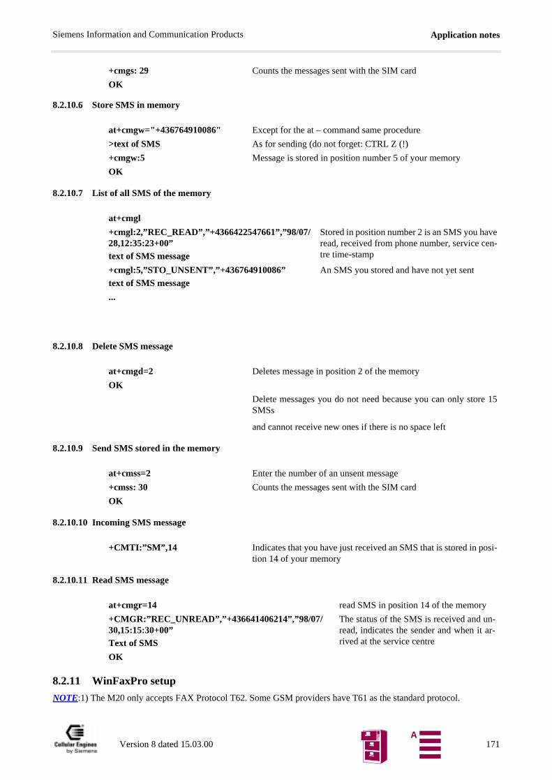
Application notesSiemens Information and Communication Products
8.2.10.6 Store SMS in memory
8.2.10.7 List of all SMS of the memory
8.2.10.8 Delete SMS message
8.2.10.9 Send SMS stored in the memory
8.2.10.10 Incoming SMS message
8.2.10.11 Read SMS message
8.2.11 WinFaxPro setup
NOTE:1) The M20 only accepts FAX Protocol T62. Some GSM providers have T61 as the standard protocol.
+cmgs: 29 Counts the messages sent with the SIM card
OK
at+cmgw="+436764910086" Except for the at – command same procedure
>text of SMS As for sending (do not forget: CTRL Z (!)
+cmgw:5 Message is stored in position number 5 of your memory
OK
at+cmgl
+cmgl:2,”REC_READ”,”+4366422547661”,”98/07/28,12:35:23+00”text of SMS message
Stored in position number 2 is an SMS you haveread, received from phone number, service cen-tre time-stamp
+cmgl:5,”STO_UNSENT”,”+436764910086”text of SMS message
An SMS you stored and have not yet sent
...
at+cmgd=2 Deletes message in position 2 of the memory
OK
Delete messages you do not need because you can only store 15SMSs
and cannot receive new ones if there is no space left
at+cmss=2 Enter the number of an unsent message
+cmss: 30 Counts the messages sent with the SIM card
OK
+CMTI:”SM”,14 Indicates that you have just received an SMS that is stored in posi-tion 14 of your memory
at+cmgr=14 read SMS in position 14 of the memory
+CMGR:”REC_UNREAD”,”+436641406214”,”98/07/30,15:15:30+00”Text of SMS
The status of the SMS is received and un-read, indicates the sender and when it ar-rived at the service centre
OK
Version 8 dated 15.03.00 171A
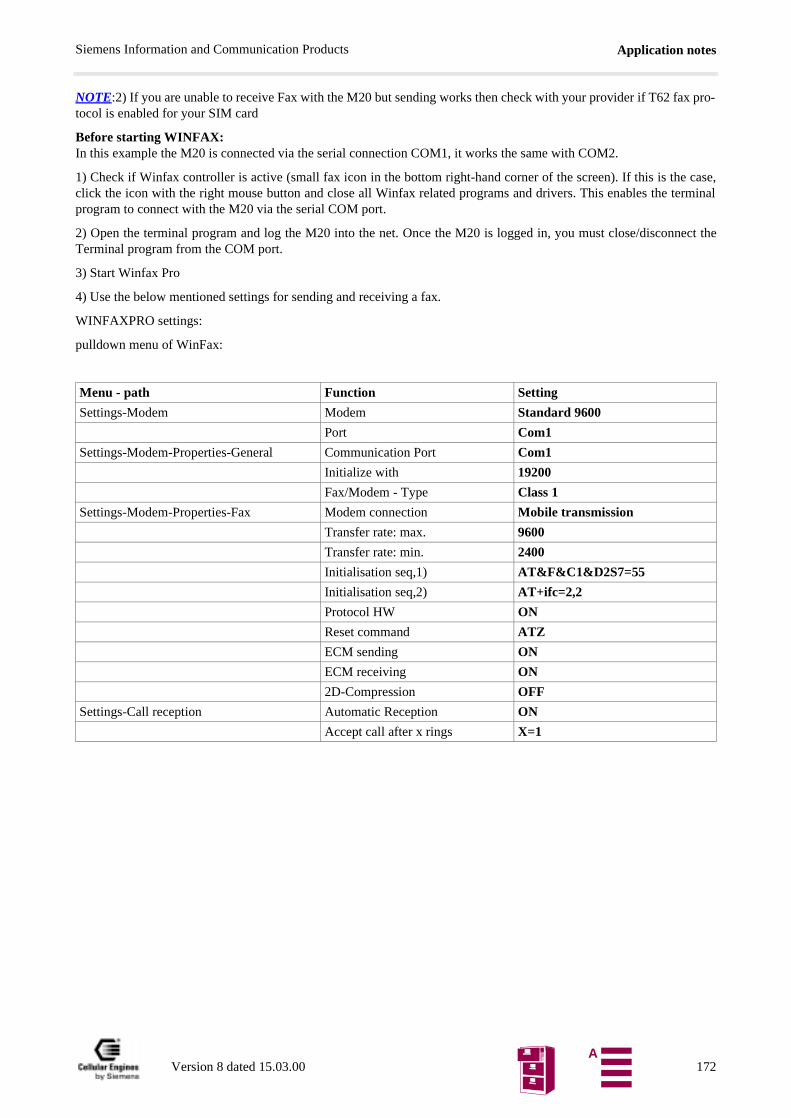
Application notesSiemens Information and Communication Products
NOTE:2) If you are unable to receive Fax with the M20 but sending works then check with your provider if T62 fax pro-tocol is enabled for your SIM card
Before starting WINFAX:In this example the M20 is connected via the serial connection COM1, it works the same with COM2.
1) Check if Winfax controller is active (small fax icon in the bottom right-hand corner of the screen). If this is the case,click the icon with the right mouse button and close all Winfax related programs and drivers. This enables the terminalprogram to connect with the M20 via the serial COM port.
2) Open the terminal program and log the M20 into the net. Once the M20 is logged in, you must close/disconnect theTerminal program from the COM port.
3) Start Winfax Pro
4) Use the below mentioned settings for sending and receiving a fax.
WINFAXPRO settings:
pulldown menu of WinFax:
Menu - path Function Setting
Settings-Modem Modem Standard 9600
Port Com1
Settings-Modem-Properties-General Communication Port Com1
Initialize with 19200
Fax/Modem - Type Class 1
Settings-Modem-Properties-Fax Modem connection Mobile transmission
Transfer rate: max. 9600
Transfer rate: min. 2400
Initialisation seq,1) AT&F&C1&D2S7=55
Initialisation seq,2) AT+ifc=2,2
Protocol HW ON
Reset command ATZ
ECM sending ON
ECM receiving ON
2D-Compression OFF
Settings-Call reception Automatic Reception ON
Accept call after x rings X=1
Version 8 dated 15.03.00 172A
Application notesSiemens Information and Communication Products
8.2.12 Provider information
(Europa_info.xls)
Comments to the expressions used:
The following information and codes are supplied by your provider:
SCSA: SMSThis is the service center address of the Provider which has to be set in the M20 when sending SMS.Setting:AT+CSCA="<CSCA number of provider>"Note: The number always has to be in the international code format starting with "+" and is enclosed in quotation marks.
Facility lock code: This code is needed when barring incoming or outgoing calls using the AT+CLCK commandThe given code is the standard setting of the provider on a new card. If the code is entered incorrectly 3 times ONLY the provider can re-activate it.
Version 8 dated 15.03.00 173A
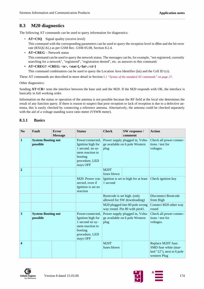
Application notesSiemens Information and Communication Products
bit error
, currently
8.3 M20 diagnosticsThe following AT commands can be used to query information for diagnostics:
• AT+CSQ Signal quality (receive level)
This command with the corresponding parameters can be used to query the reception level in dBm and therate (RXQUAL) as per GSM Rec. GSM 05.08, Section 8.2.4.
• AT+CREG – Network status
This command can be used to query the network status. The messages can be, for example, "not registeredsearching for a network", "registered", "registration denied", etc. as answers to this command.
• AT+CREG? +CREG: <n>, <stat>[,<lai>,<ci>]This command combination can be used to query the Location Area Identifier (lai) and the Cell ID (ci).
These AT commands are described in more detail in Section 5.1 “Syntax of the standard AT commands” on page 27.
Other diagnostics:
Sending AT<CR> tests the interface between the base unit and the M20. If the M20 responds with OK, the interface isbasically in full working order.
Information on the status or operation of the antenna is not possible because the RF field at the local site determines theresult of any function query. If there is reason to suspect that poor reception or lack of reception is due to a defective an-tenna, this is easily checked by connecting a reference antenna. Alternatively, the antenna could be checked separatelywith the aid of a voltage standing wave ratio meter (VSWR meter).
8.3.1 Basics
No Fault Error Message
Status Check SW response /comment
Action
1 System Booting not possible
Power connected, Ignition high for 1 second. no sy-stem reaction to booting procedure, LED stays OFF
Power supply plugged in, Volta-ge available on 6 pole Western plug
Check all power connec-tions / test for voltages.
2 M20T fuses blown
M20: Power con-nected, even if Ignition is set no reaction
Ignition is set to high for at least 1 second
Check ignition key
Bootcode is set high. (only allowed for SW downloading)
Disconnect Bootcode from High
M20 plugged into 80 pole wrong way round. Pin 80 with pin41.
Connect M20 other way round
3 System Booting not possible
Power connected, Ignition high for 1 second no sy-stem reaction to booting procedure, LED stays OFF
Power supply plugged in, Volta-ge available on 6 pole Western plug
Check all power connec-tions / test for voltages.
4 M20T fuses blown
Replace M20T fuse: SMD fuse white (mar-ked "12"), next to 6 pole western Plug
Version 8 dated 15.03.00 174A
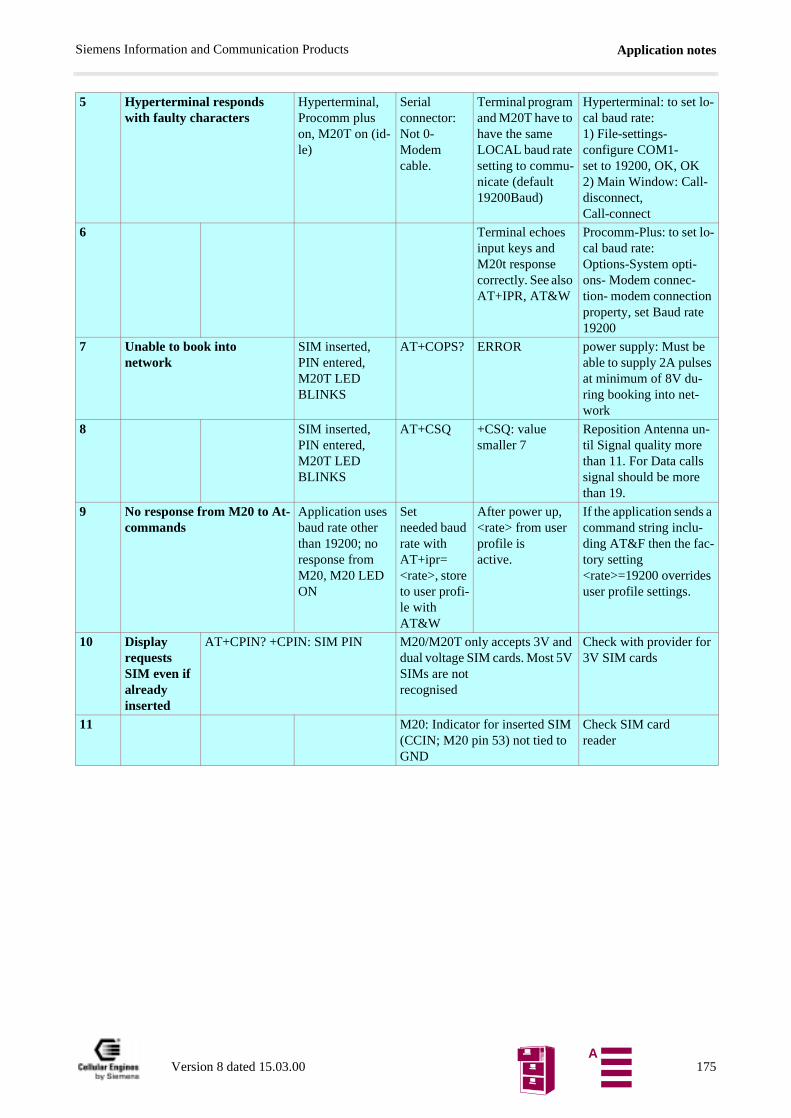
Application notesSiemens Information and Communication Products
5 Hyperterminal responds with faulty characters
Hyperterminal, Procomm plus on, M20T on (id-le)
Serial connector: Not 0-Modem cable.
Terminal program and M20T have to have the same LOCAL baud rate setting to commu-nicate (default 19200Baud)
Hyperterminal: to set lo-cal baud rate:1) File-settings-configure COM1- set to 19200, OK, OK 2) Main Window: Call-disconnect, Call-connect
6 Terminal echoes input keys and M20t response correctly. See also AT+IPR, AT&W
Procomm-Plus: to set lo-cal baud rate: Options-System opti-ons- Modem connec-tion- modem connection property, set Baud rate 19200
7 Unable to book into network
SIM inserted, PIN entered, M20T LED BLINKS
AT+COPS? ERROR power supply: Must be able to supply 2A pulses at minimum of 8V du-ring booking into net-work
8 SIM inserted, PIN entered, M20T LED BLINKS
AT+CSQ +CSQ: value smaller 7
Reposition Antenna un-til Signal quality more than 11. For Data calls signal should be more than 19.
9 No response from M20 to At-commands
Application uses baud rate other than 19200; no response from M20, M20 LED ON
Set needed baud rate with AT+ipr=<rate>, store to user profi-le with AT&W
After power up, <rate> from user profile is active.
If the application sends a command string inclu-ding AT&F then the fac-tory setting <rate>=19200 overrides user profile settings.
10 Display requests SIM even if already inserted
AT+CPIN? +CPIN: SIM PIN M20/M20T only accepts 3V and dual voltage SIM cards. Most 5V SIMs are not recognised
Check with provider for 3V SIM cards
11 M20: Indicator for inserted SIM (CCIN; M20 pin 53) not tied to GND
Check SIM card reader
Version 8 dated 15.03.00 175A

Application notesSiemens Information and Communication Products
8.3.2 Call setup
No Fault Error Message
Status Check SW response /comment
Action
1 No call setup possible
No Carrier SIM card inser-ted,(3V),Anten-na connected, Power On, Igniti-on high. M20T LED blinking
3V SIM Card?
Old SIM cards are 5V,new ones 3V. Check with Network Provider. M20 accepts only 3V SIM cards!!!!
2 AT+CSQ: Signal Qua-lity
+csq: <value>: if less 10
rearrange Antenna position, check Antenna connections, Signal Quality for pro-per function needs to be larger 12.
3 AT+CPIN?:PIN Status
ERROR No SIM-Card inserted, SIM card defective, SIM holder not inserted properly
4 +cpin: SIM PIN Enter Pin-code: AT+CPIN="xxxx" /number in quotes
5 AT+CREG? +CREG: 0,0 M20 not booked into Net: AT+COPS=0 (se-arch for Network, and book in)
6 +CREG: 0,2 M20 searching for network; when LED stops blinking, booked into network
7 AT+COPS=0
(can take up to 1 minute) +cops: <provider name>
Forces M20 to search for a network
8 No call setup possible
No Carrier M20 active, boo-ked into net (M20 idle), number exists, M20T LED ON
AT+CLCK="AO",2
+CLCK: 0 Outgoing call possible; problem has other cause.
9 +CLCK: 1,1 /Outgoing voice call barred
AT+CLCK="AO",0,"<code>",7 /Unlock all services, <code> availa-ble from Network provider (barring services)
10 +CLCK: 1,2 /Outgoing data call barred
AT+CLCK="AO",0,"<code>",7 /Unlock all services, <code> availa-ble from Network provider (barring services)
Version 8 dated 15.03.00 176A
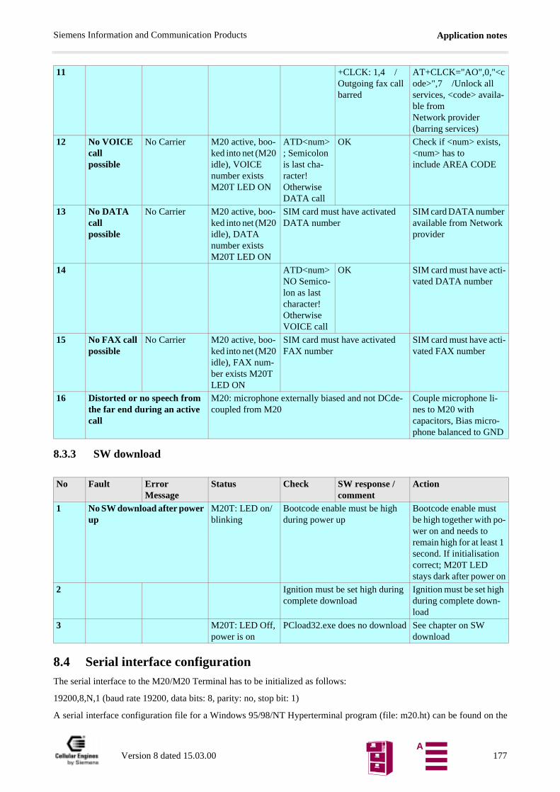
Application notesSiemens Information and Communication Products
8.3.3 SW download
8.4 Serial interface configurationThe serial interface to the M20/M20 Terminal has to be initialized as follows:
19200,8,N,1 (baud rate 19200, data bits: 8, parity: no, stop bit: 1)
A serial interface configuration file for a Windows 95/98/NT Hyperterminal program (file: m20.ht) can be found on the
11 +CLCK: 1,4 /Outgoing fax call barred
AT+CLCK="AO",0,"<code>",7 /Unlock all services, <code> availa-ble from Network provider (barring services)
12 No VOICE call possible
No Carrier M20 active, boo-ked into net (M20 idle), VOICE number exists M20T LED ON
ATD<num>; Semicolon is last cha-racter! Otherwise DATA call
OK Check if <num> exists, <num> has to include AREA CODE
13 No DATA call possible
No Carrier M20 active, boo-ked into net (M20 idle), DATA number exists M20T LED ON
SIM card must have activated DATA number
SIM card DATA number available from Network provider
14 ATD<num> NO Semico-lon as last character! Otherwise VOICE call
OK SIM card must have acti-vated DATA number
15 No FAX call possible
No Carrier M20 active, boo-ked into net (M20 idle), FAX num-ber exists M20T LED ON
SIM card must have activated FAX number
SIM card must have acti-vated FAX number
16 Distorted or no speech from the far end during an active call
M20: microphone externally biased and not DCde-coupled from M20
Couple microphone li-nes to M20 with capacitors, Bias micro-phone balanced to GND
No Fault Error Message
Status Check SW response /comment
Action
1 No SW download after power up
M20T: LED on/blinking
Bootcode enable must be high during power up
Bootcode enable must be high together with po-wer on and needs to remain high for at least 1 second. If initialisation correct; M20T LED stays dark after power on
2 Ignition must be set high during complete download
Ignition must be set high during complete down-load
3 M20T: LED Off, power is on
PCload32.exe does no download See chapter on SW download
Version 8 dated 15.03.00 177A
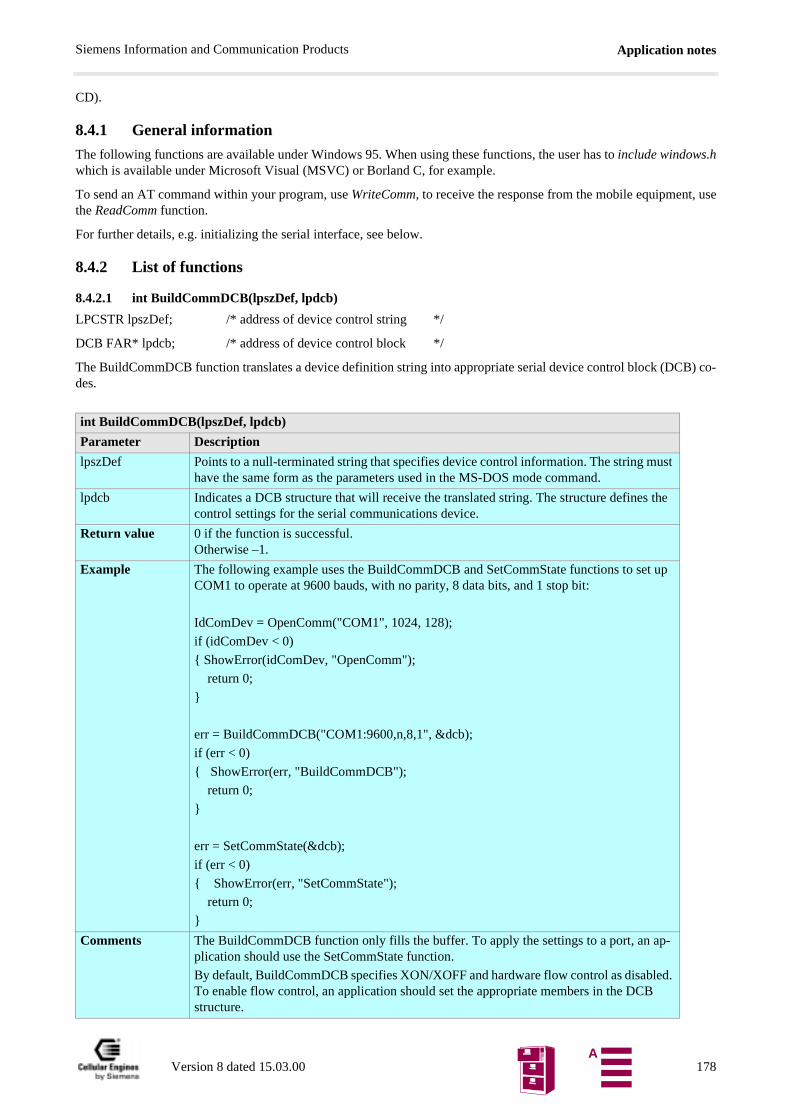
Application notesSiemens Information and Communication Products
CD).
8.4.1 General information
The following functions are available under Windows 95. When using these functions, the user has to include windows.hwhich is available under Microsoft Visual (MSVC) or Borland C, for example.
To send an AT command within your program, use WriteComm, to receive the response from the mobile equipment, usethe ReadComm function.
For further details, e.g. initializing the serial interface, see below.
8.4.2 List of functions
8.4.2.1 int BuildCommDCB(lpszDef, lpdcb)
LPCSTR lpszDef; /* address of device control string */
DCB FAR* lpdcb; /* address of device control block */
The BuildCommDCB function translates a device definition string into appropriate serial device control block (DCB) co-des.
int BuildCommDCB(lpszDef, lpdcb)
Parameter Description
lpszDef Points to a null-terminated string that specifies device control information. The string must have the same form as the parameters used in the MS-DOS mode command.
lpdcb Indicates a DCB structure that will receive the translated string. The structure defines the control settings for the serial communications device.
Return value 0 if the function is successful. Otherwise –1.
Example The following example uses the BuildCommDCB and SetCommState functions to set up COM1 to operate at 9600 bauds, with no parity, 8 data bits, and 1 stop bit:
IdComDev = OpenComm("COM1", 1024, 128);
if (idComDev < 0)
ShowError(idComDev, "OpenComm");
return 0;
err = BuildCommDCB("COM1:9600,n,8,1", &dcb);
if (err < 0)
ShowError(err, "BuildCommDCB");
return 0;
err = SetCommState(&dcb);
if (err < 0)
ShowError(err, "SetCommState");
return 0;
Comments The BuildCommDCB function only fills the buffer. To apply the settings to a port, an ap-plication should use the SetCommState function.
By default, BuildCommDCB specifies XON/XOFF and hardware flow control as disabled. To enable flow control, an application should set the appropriate members in the DCB structure.
Version 8 dated 15.03.00 178A
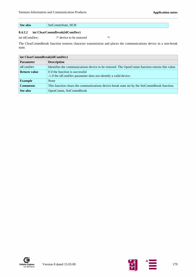
Application notesSiemens Information and Communication Products
8.4.2.2 int ClearCommBreak(idComDev)
int idComDev; /* device to be restored */
The ClearCommBreak function restores character transmission and places the communications device in a non-breakstate.
See also SetCommState, DCB
int ClearCommBreak(idComDev)
Parameter Description
idComDev Identifies the communications device to be restored. The OpenComm function returns this value.
Return value 0 if the function is successful-1 if the idComDev parameter does not identify a valid device.
Example None
Comments This function clears the communications device break state set by the SetCommBreak function.
See also OpenComm, SetCommBreak
Version 8 dated 15.03.00 179A
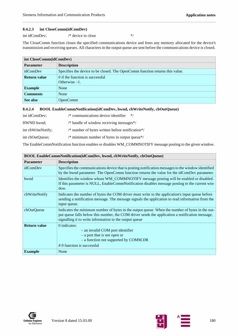
Application notesSiemens Information and Communication Products
tified eter.
ed. win-
fore m the
e out-age,
8.4.2.3 int CloseComm(idComDev)
int idComDev; /* device to close */
The CloseComm function closes the specified communications device and frees any memory allocated for the device’stransmission and receiving queues. All characters in the output queue are sent before the communications device is closed.
8.4.2.4 BOOL EnableCommNotification(idComDev, hwnd, cbWriteNotify, cbOutQueue)
int idComDev; /* communications device identifier */
HWND hwnd; /* handle of window receiving messages*/
int cbWriteNotify; /* number of bytes written before notification*/
int cbOutQueue; /* minimum number of bytes in output queue*/
The EnableCommNotification function enables or disables WM_COMMNOTIFY message posting to the given window.
int CloseComm(idComDev)
Parameter Description
idComDev Specifies the device to be closed. The OpenComm function returns this value.
Return value 0 if the function is successfulOtherwise –1.
Example None
Comments None
See also OpenComm
BOOL EnableCommNotification(idComDev, hwnd, cbWriteNotify, cbOutQueue)
Parameter Description
idComDev Specifies the communications device that is posting notification messages to the window idenby the hwnd parameter. The OpenComm function returns the value for the idComDev param
hwnd Identifies the window whose WM_COMMNOTIFY message posting will be enabled or disablIf this parameter is NULL, EnableCommNotification disables message posting to the currentdow.
cbWriteNotify Indicates the number of bytes the COM driver must write to the application's input queue besending a notification message. The message signals the application to read information froinput queue.
cbOutQueue Indicates the minimum number of bytes in the output queue. When the number of bytes in thput queue falls below this number, the COM driver sends the application a notification messsignalling it to write information to the output queue
Return value 0 indicates:– an invalid COM port identifier– a port that is not open or– a function not supported by COMM.DR
≠ 0 function is successful
Example None
Version 8 dated 15.03.00 180A
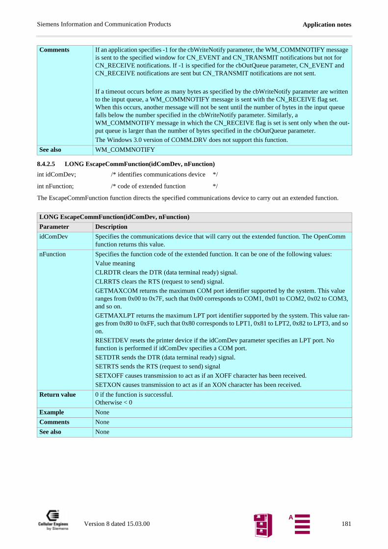
Application notesSiemens Information and Communication Products
8.4.2.5 LONG EscapeCommFunction(idComDev, nFunction)
int idComDev; /* identifies communications device */
int nFunction; /* code of extended function */
The EscapeCommFunction function directs the specified communications device to carry out an extended function.
Comments If an application specifies -1 for the cbWriteNotify parameter, the WM_COMMNOTIFY message is sent to the specified window for CN_EVENT and CN_TRANSMIT notifications but not for CN_RECEIVE notifications. If -1 is specified for the cbOutQueue parameter, CN_EVENT and CN_RECEIVE notifications are sent but CN_TRANSMIT notifications are not sent.
If a timeout occurs before as many bytes as specified by the cbWriteNotify parameter are written to the input queue, a WM_COMMNOTIFY message is sent with the CN_RECEIVE flag set. When this occurs, another message will not be sent until the number of bytes in the input queue falls below the number specified in the cbWriteNotify parameter. Similarly, a WM_COMMNOTIFY message in which the CN_RECEIVE flag is set is sent only when the out-put queue is larger than the number of bytes specified in the cbOutQueue parameter.
The Windows 3.0 version of COMM.DRV does not support this function.
See also WM_COMMNOTIFY
LONG EscapeCommFunction(idComDev, nFunction)
Parameter Description
idComDev Specifies the communications device that will carry out the extended function. The OpenComm function returns this value.
nFunction Specifies the function code of the extended function. It can be one of the following values:
Value meaning
CLRDTR clears the DTR (data terminal ready) signal.
CLRRTS clears the RTS (request to send) signal.
GETMAXCOM returns the maximum COM port identifier supported by the system. This value ranges from 0x00 to 0x7F, such that 0x00 corresponds to COM1, 0x01 to COM2, 0x02 to COM3, and so on.
GETMAXLPT returns the maximum LPT port identifier supported by the system. This value ran-ges from 0x80 to 0xFF, such that 0x80 corresponds to LPT1, 0x81 to LPT2, 0x82 to LPT3, and so on.
RESETDEV resets the printer device if the idComDev parameter specifies an LPT port. No function is performed if idComDev specifies a COM port.
SETDTR sends the DTR (data terminal ready) signal.
SETRTS sends the RTS (request to send) signal
SETXOFF causes transmission to act as if an XOFF character has been received.
SETXON causes transmission to act as if an XON character has been received.
Return value 0 if the function is successful. Otherwise < 0
Example None
Comments None
See also None
Version 8 dated 15.03.00 181A

Application notesSiemens Information and Communication Products
8.4.2.6 int FlushComm(idComDev, fnQueue)
int idComDev; /* communications-device identifier */
int fnQueue; /* queue to flush */
The FlushComm function flushes all characters from the transmission or receiving queue of the specified communicationsdevice.
int FlushComm(idComDev, fnQueue)
Parameter Description
idComDev Specifies the communications device to be flushed. The OpenComm function returns this value.
fnQueue Specifies the queue to be flushed. The transmission queue is flushed if this parameter is ze-ro. The receiving queue is flushed if the parameter is 1.
Return value 0 if the function is successful.
< 0 if idComDev is not a valid device or if fnQueue is not a valid queue
> 0 if there is an error for the specified device. For a list of the possible error values, see the GetCommError function.
Example None
Comments None
See also GetCommError, OpenComm
Version 8 dated 15.03.00 182A
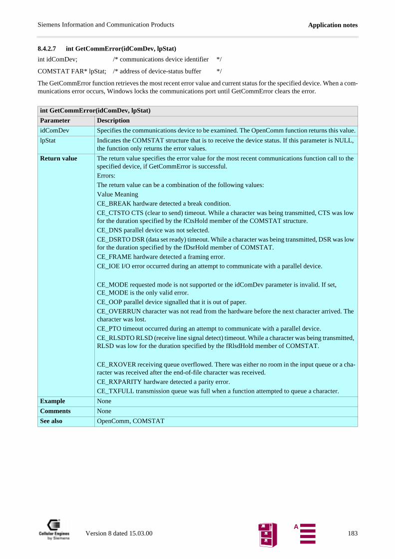
Application notesSiemens Information and Communication Products
8.4.2.7 int GetCommError(idComDev, lpStat)
int idComDev; /* communications device identifier */
COMSTAT FAR* lpStat; /* address of device-status buffer */
The GetCommError function retrieves the most recent error value and current status for the specified device. When a com-munications error occurs, Windows locks the communications port until GetCommError clears the error.
int GetCommError(idComDev, lpStat)
Parameter Description
idComDev Specifies the communications device to be examined. The OpenComm function returns this value.
lpStat Indicates the COMSTAT structure that is to receive the device status. If this parameter is NULL, the function only returns the error values.
Return value The return value specifies the error value for the most recent communications function call to the specified device, if GetCommError is successful.
Errors:
The return value can be a combination of the following values:
Value Meaning
CE_BREAK hardware detected a break condition.
CE_CTSTO CTS (clear to send) timeout. While a character was being transmitted, CTS was low for the duration specified by the fCtsHold member of the COMSTAT structure.
CE_DNS parallel device was not selected.
CE_DSRTO DSR (data set ready) timeout. While a character was being transmitted, DSR was low for the duration specified by the fDsrHold member of COMSTAT.
CE_FRAME hardware detected a framing error.
CE_IOE I/O error occurred during an attempt to communicate with a parallel device.
CE_MODE requested mode is not supported or the idComDev parameter is invalid. If set, CE_MODE is the only valid error.
CE_OOP parallel device signalled that it is out of paper.
CE_OVERRUN character was not read from the hardware before the next character arrived. The character was lost.
CE_PTO timeout occurred during an attempt to communicate with a parallel device.
CE_RLSDTO RLSD (receive line signal detect) timeout. While a character was being transmitted, RLSD was low for the duration specified by the fRlsdHold member of COMSTAT.
CE_RXOVER receiving queue overflowed. There was either no room in the input queue or a cha-racter was received after the end-of-file character was received.
CE_RXPARITY hardware detected a parity error.
CE_TXFULL transmission queue was full when a function attempted to queue a character.
Example None
Comments None
See also OpenComm, COMSTAT
Version 8 dated 15.03.00 183A
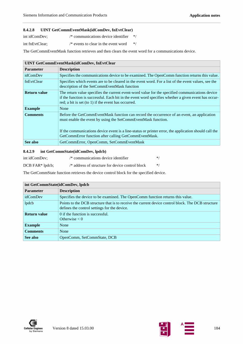
Application notesSiemens Information and Communication Products
8.4.2.8 UINT GetCommEventMask(idComDev, fnEvtClear)
int idComDev; /* communications device identifier */
int fnEvtClear; /* events to clear in the event word */
The GetCommEventMask function retrieves and then clears the event word for a communications device.
8.4.2.9 int GetCommState(idComDev, lpdcb)
int idComDev; /* communications device identifier */
DCB FAR* lpdcb; /* address of structure for device control block */
The GetCommState function retrieves the device control block for the specified device.
UINT GetCommEventMask(idComDev, fnEvtClear
Parameter Description
idComDev Specifies the communications device to be examined. The OpenComm function returns this value.
fnEvtClear Specifies which events are to be cleared in the event word. For a list of the event values, see the description of the SetCommEventMask function
Return value The return value specifies the current event-word value for the specified communications device if the function is successful. Each bit in the event word specifies whether a given event has occur-red; a bit is set (to 1) if the event has occurred.
Example None
Comments Before the GetCommEventMask function can record the occurrence of an event, an application must enable the event by using the SetCommEventMask function.
If the communications device event is a line-status or printer error, the application should call the GetCommError function after calling GetCommEventMask.
See also GetCommError, OpenComm, SetCommEventMask
int GetCommState(idComDev, lpdcb
Parameter Description
idComDev Specifies the device to be examined. The OpenComm function returns this value.
lpdcb Points to the DCB structure that is to receive the current device control block. The DCB structure defines the control settings for the device.
Return value 0 if the function is successful. Otherwise < 0
Example None
Comments None
See also OpenComm, SetCommState, DCB
Version 8 dated 15.03.00 184A

Application notesSiemens Information and Communication Products
8.4.2.10 int OpenComm(lpszDevControl, cbInQueue, cbOutQueue)
LPCSTR lpszDevControl;/* address of device-control information */
UINT cbInQueue; /* size of receiving queue */
UINT cbOutQueue; /* size of transmission queue */
The OpenComm function opens a communications device.
int OpenComm(lpszDevControl, cbInQueue, cbOutQueue
Parameter Description
lpszDevControl Points to a null-terminated string that specifies the device in the form COMn or LPTn, where n is the device number.
cbInQueue Specifies the size, in bytes, of the receiving queue. This parameter is ignored for LPT devices.
cbOutQueue Specifies the size, in bytes, of the transmission queue. This parameter is ignored for LPT devices.
Return value ≥ 0 the return value identifies the open device if the function is successful.
Otherwise < 0
Errors:
If the function fails, it may return one of the following error values:
Value Meaning
IE_BADID the device identifier is invalid or unsupported.
IE_BAUDRATE the device’s baud rate is unsupported.
IE_BYTESIZE the specified byte size is invalid.
IE_DEFAULT the default parameters are in error.
IE_HARDWARE the hardware is not available (is locked by another device).
IE_MEMORY the function cannot allocate the queues.
IE_NOPEN the device is not open.
IE_OPEN the device is already open.
If this function is called with both queue sizes set to zero, the return value is:
IE_OPEN if the device is already open or
IE_MEMORY if the device is not open.
Example The following example uses the OpenComm function to open communications port 1:
idComDev = OpenComm("COM1", 1024, 128);
if (idComDev < 0)
ShowError(idComDev, "OpenComm");
return 0;
err = BuildCommDCB("COM1:9600,n,8,1", &dcb);
if (err < 0)
ShowError(err, "BuildCommDCB");
return 0;
err = SetCommState(&dcb);
if (err < 0)
ShowError(err, "SetCommState");
return 0;
Version 8 dated 15.03.00 185A
Application notesSiemens Information and Communication Products
Comments Windows allows COM ports 1 through 9 and LPT ports 1 through 3. The OpenComm function will fail if the device driver does not support a communications port number.
The communications device is initialized to a default configuration. The SetCommState function should be used to initialize the device to alternate values.
The receiving and transmission queues are used by interrupt-driven device drivers. LPT ports are not interrupt-driven for these ports, the cbInQueue and cbOutQueue parameters are ignored and the queue size is set to zero.
See also CloseComm, SetCommState
Version 8 dated 15.03.00 186A
Application notesSiemens Information and Communication Products
8.4.2.11 int ReadComm(idComDev, lpvBuf, cbRead)
int idComDev;/* identifier of device to read from */
void FAR* lpvBuf; /* address of buffer for read bytes */
int cbRead; /* number of bytes to read */
The ReadComm function reads up to a specified number of bytes from the given communications device.
8.4.2.12 int SetCommBreak(idComDev)
int idComDev; /* device to suspend */
The SetCommBreak function suspends character transmission and places the communications device in a break state.
int ReadComm(idComDev, lpvBuf, cbRead)
Parameter Description
idComDev Specifies the communications device to be read from. The OpenComm function returns this value.
lpvBuf Points to the buffer for the read bytes.
cbRead Specifies the number of bytes to be read.
Return value ≥ 0 the number of bytes read, if the function is successful.
0 For parallel I/O ports, the return value is always zero.
Otherwise < 0, its absolute value is the number of bytes read
Example None
Comments When an error occurs, the cause of the error can be determined by using the GetCommError function to retrieve the error value and status. Since errors can occur when no bytes are present (if the return value is zero), the GetCommError function should be used to ensure that no error occur-red.
The return value is less than the number specified by the cbRead parameter only if the number of bytes in the receiving queue is less than that specified by cbRead. If the return value is equal to cbRead, additional bytes may be queued for the device. If the return value is zero, no bytes are pre-sent.
See also GetCommError, OpenComm
int SetCommBreak(idComDev)
Parameter Description
idComDev Specifies the communications device to be suspended. The OpenComm function returns this value.
Return value 0 if the function is successful.
Otherwise < 0
Example None
Comments The communications device remains suspended until the application calls the ClearCommBreak function.
See also ClearCommBreak, OpenComm
Version 8 dated 15.03.00 187A
Application notesSiemens Information and Communication Products
8.4.2.13 UINT FAR* SetCommEventMask(idComDev, fuEvtMask)
int idComDev; /* device to enable */
UINT fuEvtMask; /* events to enable */
The SetCommEventMask function enables events in the event word of the specified communications device.
UINT FAR* SetCommEventMask(idComDev, fuEvtMask)
Parameter Description
idComDev Specifies the communications device to be enabled. The OpenComm function returns this value.
fuEvtMask Specifies which events are to be enabled.
This parameter can be any combination of the following values:
Value meaning
EV_BREAK set when a break is detected on input.
EV_CTS set when the CTS (clear to send) signal changes state.
EV_CTS set when the CTS (clear to send) signal changes state.
EV_CTSS set to indicate the current state of the CTS signal.
EV_DSR set when the DSR (data set ready) signal changes state.
EV_ERR set when a line-status error occurs. Line-status errors are CE_FRAME, CE_OVERRUN, and CE_RXPARITY.
EV_PERR set when a printer error is detected on a parallel device. Errors are CE_DNS, CE_IOE, CE_LOOP, and CE_PTO.
EV_RING set to indicate the state of ring indicator during the last modem interrupt.
EV_RLSD set when the RLSD (receive line signal detect) signal changes state.
EV_RLSDS set to indicate the current state of the RLSD signal.
EV_RXCHAR set when any character is received and placed in the receiving queue.
EV_RXFLAG set when the event character is received and placed in the receiving queue. The event character is specified in the device’s control block.
EV_TXEMPTY set when the last character in the transmission queue is sent.
Return value The return value is an indication to the event-word for the specified communications device, if the function is successful. Each bit in the event word specifies whether a given event has occurred. A bit is 1 if the event has occurred.
Example None
Comments Only enabled events are recorded. The GetCommEventMask function retrieves and clears the event word.
See also GetCommEventMask, OpenComm
Version 8 dated 15.03.00 188A
Application notesSiemens Information and Communication Products
8.4.2.14 int SetCommState(lpdcb)
const DCB FAR* lpdcb; /* address of device control block */
The SetCommState function sets a communications device to the state specified by a device control block.
int SetCommState(lpdcb)
Parameter Description
lpdcb Indicates a DCB structure that contains the desired communications settings for the device. The ID member of the DCB structure must identify the device.
Return value 0 if the function is successful.
Otherwise < 0
Example The following example uses the BuildCommDCB and SetCommState functions to set up COM1 at 9600 baud, no parity, 8 data bits, and 1 stop bit:
idComDev = OpenComm("COM1", 1024, 128);
if (idComDev < 0)
ShowError(idComDev, "OpenComm");
return 0;
err = BuildCommDCB("COM1:9600,n,8,1", &dcb);
if (err < 0)
ShowError(err, "BuildCommDCB");
return 0;
err = SetCommState(&dcb);
if (err < 0)
ShowError(err, "SetCommState");
return 0;
Comments This function reinitializes all hardware and controls as defined by the DCB structure, but it does not empty transmission or receiving queues.
See also GetCommState, DCB
Version 8 dated 15.03.00 189A
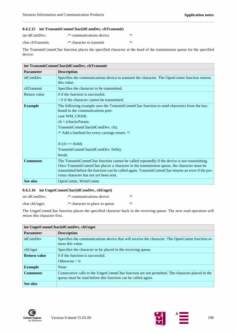
Application notesSiemens Information and Communication Products
8.4.2.15 int TransmitCommChar(idComDev, chTransmit)
int idComDev; /* communications device */
char chTransmit; /* character to transmit */
The TransmitCommChar function places the specified character at the head of the transmission queue for the specifieddevice.
8.4.2.16 int UngetCommChar(idComDev, chUnget)
int idComDev; /* communications device */
char chUnget; /* character to place in queue */
The UngetCommChar function places the specified character back in the receiving queue. The next read operation willreturn this character first.
int TransmitCommChar(idComDev, chTransmit
Parameter Description
idComDev Specifies the communications device to transmit the character. The OpenComm function returns this value.
chTransmit Specifies the character to be transmitted.
Return value 0 if the function is successful.
< 0 if the character cannot be transmitted.
Example The following example uses the TransmitCommChar function to send characters from the key-board to the communications port:
case WM_CHAR:
ch = (char)wParam;
TransmitCommChar(idComDev, ch);
/* Add a linefeed for every carriage return. */
if (ch == 0x0d)
TransmitCommChar(idComDev, 0x0a);
break;
Comments The TransmitCommChar function cannot be called repeatedly if the device is not transmitting. Once TransmitCommChar places a character in the transmission queue, the character must be transmitted before the function can be called again. TransmitCommChar returns an error if the pre-vious character has not yet been sent.
See also OpenComm, WriteComm
int UngetCommChar(idComDev, chUnget
Parameter Description
idComDev Specifies the communications device that will receive the character. The OpenComm function re-turns this value.
chUnget Specifies the character to be placed in the receiving queue.
Return value 0 if the function is successful.
Otherwise < 0
Example None
Comments Consecutive calls to the UngetCommChar function are not permitted. The character placed in the queue must be read before this function can be called again.
See also
Version 8 dated 15.03.00 190A

Application notesSiemens Information and Communication Products
8.4.2.17 int WriteComm(idComDev, lpvBuf, cbWrite)
int idComDev; /* identifier of comm. device */
const void FAR* lpvBuf; /* address of data buffer */
int cbWrite; /* number of bytes to write */
The WriteComm function writes to the specified communications device.
8.5 SW download (Version update)The Flashloader functions under Windows 95/98/NT for updating and loading SW into the M20 module via the serialinterface of the M20Terminal. An implementation of SW download without using the M20T module is also described.
8.5.1 M20: HW setup
For Downloading SW into the M20 without the use of the M20T, following preparations have to be made to enable M20to communicate with the PC via the serial interface cable.
Tools and components required:If not already installed on the application a minimum serial interface 1) between the M20 and a computer is required.(Thesignals RTS, CTS, DSR and DTR are not necessary for SW-update.)
Note: 1) The signals RTS, CTS, DSR and DTR are not necessary for SW-update.
int WriteComm(idComDev, lpvBuf, cbWrite)
Parameter Description
idComDev Specifies the device to receive the bytes. The OpenComm function returns this value.
lpvBuf Points to the buffer that contains the bytes to be written.
cbWrite Specifies the number of bytes to be written.
Return value The return value specifies the number of bytes written, if the function is successful.
< 0 if an error occurs, making the absolute value of the return value the number of bytes written.
Example None
Comments To determine what caused an error, use the GetCommError function to retrieve the error value and status.
For serial ports, the WriteComm function deletes data in the transmission queue if there is not enough room in the queue for the additional bytes. Before calling WriteComm, applications should check the available space in the transmission queue by using the GetCommError function. Also, applications should use the OpenComm function to set the size of the transmission queue to an amount no smaller than the size of the largest expected output string.
See also GetCommError, OpenComm, TransmitCommChar
M20 pins Signal Comments18-22, 58-62 DC_IN -
17, 23-25, 38, 43, 56, 57, 63-65
GND -
8 IGNITION Connect IGNITION to DC_IN
30 BOOTCODEEN 2) Provide a switch between BOOTCODEEN and POWER_ON.
74 POWER_ON
10 USCRX A level shifter from 2.8 V logic to V.24/RS232 is required (must be connected to pin 3 on a computers 9-pin Sub-D serial port)
72 USCTX A level shifter from 2.8 V logic to V.24/RS232 is required (must be connected to pin 2 on a computers 9-pin Sub-D serial port)
Version 8 dated 15.03.00 191A
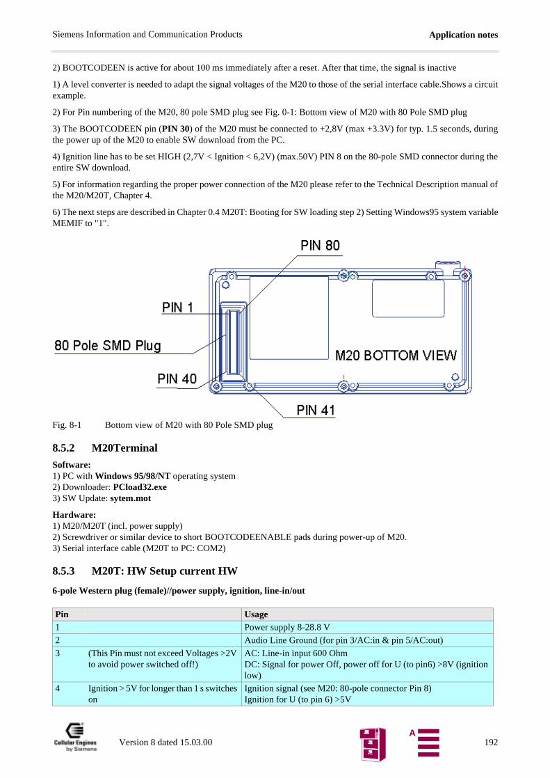
Application notesSiemens Information and Communication Products
2) BOOTCODEEN is active for about 100 ms immediately after a reset. After that time, the signal is inactive
1) A level converter is needed to adapt the signal voltages of the M20 to those of the serial interface cable.Shows a circuitexample.
2) For Pin numbering of the M20, 80 pole SMD plug see Fig. 0-1: Bottom view of M20 with 80 Pole SMD plug
3) The BOOTCODEEN pin (PIN 30) of the M20 must be connected to +2,8V (max +3.3V) for typ. 1.5 seconds, duringthe power up of the M20 to enable SW download from the PC.
4) Ignition line has to be set HIGH (2,7V < Ignition < 6,2V) (max.50V) PIN 8 on the 80-pole SMD connector during theentire SW download.
5) For information regarding the proper power connection of the M20 please refer to the Technical Description manual ofthe M20/M20T, Chapter 4.
6) The next steps are described in Chapter 0.4 M20T: Booting for SW loading step 2) Setting Windows95 system variableMEMIF to "1".
Fig. 8-1 Bottom view of M20 with 80 Pole SMD plug
8.5.2 M20Terminal
Software:1) PC with Windows 95/98/NT operating system2) Downloader: PCload32.exe 3) SW Update: sytem.mot
Hardware:1) M20/M20T (incl. power supply)2) Screwdriver or similar device to short BOOTCODEENABLE pads during power-up of M20.3) Serial interface cable (M20T to PC: COM2)
8.5.3 M20T: HW Setup current HW
6-pole Western plug (female)//power supply, ignition, line-in/out
Pin Usage1 Power supply 8-28.8 V
2 Audio Line Ground (for pin 3/AC:in & pin 5/AC:out)
3 (This Pin must not exceed Voltages >2V to avoid power switched off!)
AC: Line-in input 600 OhmDC: Signal for power Off, power off for U (to pin6) >8V (ignition low)
4 Ignition > 5V for longer than 1 s switches on
Ignition signal (see M20: 80-pole connector Pin 8)Ignition for U (to pin 6) >5V
Version 8 dated 15.03.00 192A
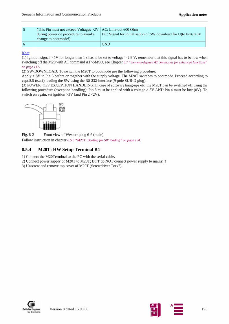
Application notesSiemens Information and Communication Products
ns”
Note:(1) Ignition signal > 5V for longer than 1 s has to be set to voltage > 2.8 V, remember that this signal has to be low whenswitching off the M20 with AT command AT^SMSO, see Chapter 5.7 “Siemens-defined AT commands for enhanced functioon page 111.(2) SW-DOWNLOAD: To switch the M20T to bootmode use the following procedure:Apply > 8V to Pin 5 before or together with the supply voltage. The M20T switches to bootmode. Proceed according tocapt.8.5 (e.a.?) loading the SW using the RS 232-interface (9-pole SUB-D plug).(3) POWER_OFF EXCEPTION HANDLING: In case of software hang-ups etc. the M20T can be switched off using thefollowing procedure (exception handling): Pin 3 must be applied with a voltage > 8V AND Pin 4 must be low (0V). Toswitch on again, set ignition >5V (and Pin 2 <2V).
Fig. 8-2 Front view of Western plug 6-6 (male)
Follow instruction in chapter 8.5.5 “M20T: Booting for SW loading” on page 194.
8.5.4 M20T: HW Setup Terminal B4
1) Connect the M20Terminal to the PC with the serial cable.2) Connect power supply of M20T to M20T; BUT do NOT connect power supply to mains!!!3) Unscrew and remove top cover of M20T (Screwdriver Torx7).
5 (This Pin must not exceed Voltages >2V during power on procedure to avoid a change to bootmode!)
AC: Line-out 600 OhmDC: Signal for initialisation of SW download for U(to Pin6)>8V
6 GND
Version 8 dated 15.03.00 193A
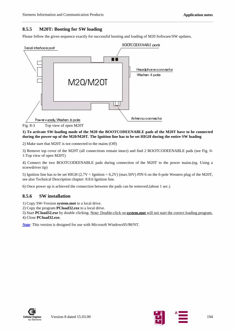
Application notesSiemens Information and Communication Products
8.5.5 M20T: Booting for SW loading
Please follow the given sequence exactly for successful booting and loading of M20 Software/SW updates.
Fig. 8-3 Top view of open M20T
1) To activate SW-loading mode of the M20 the BOOTCODEENABLE pads of the M20T have to be connectedduring the power-up of the M20/M20T. The Ignition line has to be set HIGH during the entire SW loading
2) Make sure that M20T is not connected to the mains (Off)
3) Remove top cover of the M20T (all connections remain intact) and find 2 BOOTCODEENABLE pads (see Fig. 0-1:Top view of open M20T)
4) Connect the two BOOTCODEENABLE pads during connection of the M20T to the power mains.(eg. Using ascrewdriver tip)
5) Ignition line has to be set HIGH (2,7V < Ignition < 6,2V) (max.50V) PIN 6 on the 6-pole Western plug of the M20T,see also Technical Description chapter: 8.8.6 Ignition line.
6) Once power up is achieved the connection between the pads can be removed.(about 1 sec.)
8.5.6 SW installation
1) Copy SW-Version system.mot to a local drive.2) Copy the program PCload32.exe to a local drive.3) Start PCload32.exe by double clicking. Note: Double-click on system.mot will not start the correct loading program.4) Close PCload32.exe.
Note: This version is designed for use with Microsoft Windows95/98/NT.
Version 8 dated 15.03.00 194A
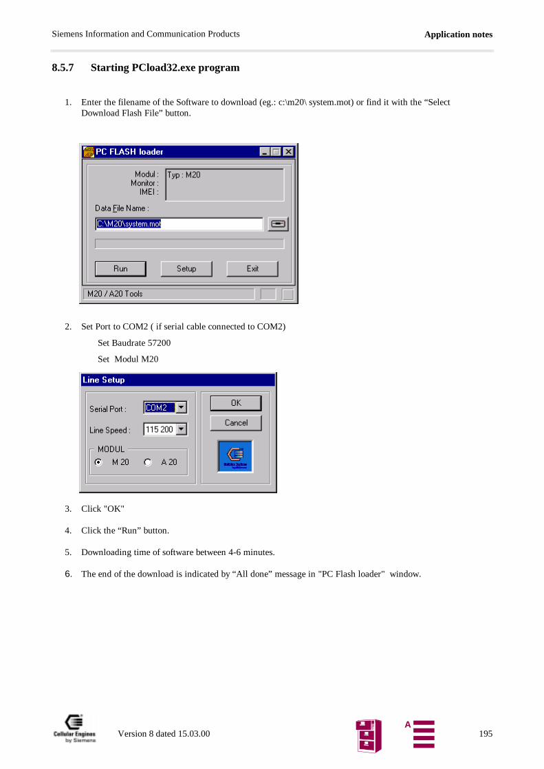
Application notesSiemens Information and Communication Products
8.5.7 Starting PCload32.exe program
1. Enter the filename of the Software to download (eg.: c:\m20\ system.mot) or find it with the “SelectDownload Flash File” button.
2. Set Port to COM2 ( if serial cable connected to COM2)
Set Baudrate 57200
Set Modul M20
3. Click "OK"
4. Click the “Run” button.
5. Downloading time of software between 4-6 minutes.
6. The end of the download is indicated by “All done” message in "PC Flash loader" window.
Version 8 dated 15.03.00 195A
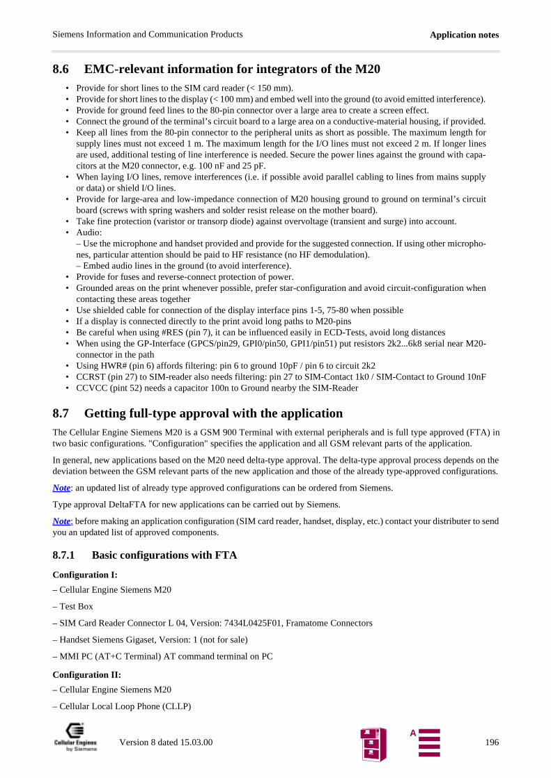
Application notesSiemens Information and Communication Products
ce).
ed. for
nes
ply
uit
pho-
hen
20-
nF
TA) in
nds on theurations.
to send
8.6 EMC-relevant information for integrators of the M20• Provide for short lines to the SIM card reader (< 150 mm).• Provide for short lines to the display (< 100 mm) and embed well into the ground (to avoid emitted interferen• Provide for ground feed lines to the 80-pin connector over a large area to create a screen effect.• Connect the ground of the terminal’s circuit board to a large area on a conductive-material housing, if provid• Keep all lines from the 80-pin connector to the peripheral units as short as possible. The maximum length
supply lines must not exceed 1 m. The maximum length for the I/O lines must not exceed 2 m. If longer liare used, additional testing of line interference is needed. Secure the power lines against the ground with capa-citors at the M20 connector, e.g. 100 nF and 25 pF.
• When laying I/O lines, remove interferences (i.e. if possible avoid parallel cabling to lines from mains supor data) or shield I/O lines.
• Provide for large-area and low-impedance connection of M20 housing ground to ground on terminal’s circboard (screws with spring washers and solder resist release on the mother board).
• Take fine protection (varistor or transorp diode) against overvoltage (transient and surge) into account.• Audio:
– Use the microphone and handset provided and provide for the suggested connection. If using other micrones, particular attention should be paid to HF resistance (no HF demodulation).– Embed audio lines in the ground (to avoid interference).
• Provide for fuses and reverse-connect protection of power.• Grounded areas on the print whenever possible, prefer star-configuration and avoid circuit-configuration w
contacting these areas together• Use shielded cable for connection of the display interface pins 1-5, 75-80 when possible• If a display is connected directly to the print avoid long paths to M20-pins• Be careful when using #RES (pin 7), it can be influenced easily in ECD-Tests, avoid long distances• When using the GP-Interface (GPCS/pin29, GPI0/pin50, GPI1/pin51) put resistors 2k2...6k8 serial near M
connector in the path• Using HWR# (pin 6) affords filtering: pin 6 to ground 10pF / pin 6 to circuit 2k2• CCRST (pin 27) to SIM-reader also needs filtering: pin 27 to SIM-Contact 1k0 / SIM-Contact to Ground 10• CCVCC (pint 52) needs a capacitor 100n to Ground nearby the SIM-Reader
8.7 Getting full-type approval with the applicationThe Cellular Engine Siemens M20 is a GSM 900 Terminal with external peripherals and is full type approved (Ftwo basic configurations. "Configuration" specifies the application and all GSM relevant parts of the application.
In general, new applications based on the M20 need delta-type approval. The delta-type approval process depedeviation between the GSM relevant parts of the new application and those of the already type-approved config
Note: an updated list of already type approved configurations can be ordered from Siemens.
Type approval DeltaFTA for new applications can be carried out by Siemens.
Note: before making an application configuration (SIM card reader, handset, display, etc.) contact your distributeryou an updated list of approved components.
8.7.1 Basic configurations with FTA
Configuration I:
– Cellular Engine Siemens M20
– Test Box
– SIM Card Reader Connector L 04, Version: 7434L0425F01, Framatome Connectors
– Handset Siemens Gigaset, Version: 1 (not for sale)
– MMI PC (AT+C Terminal) AT command terminal on PC
Configuration II:
– Cellular Engine Siemens M20
– Cellular Local Loop Phone (CLLP)
Version 8 dated 15.03.00 196A
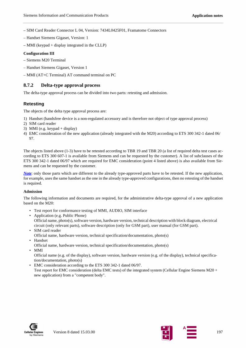
Application notesSiemens Information and Communication Products
)
ed 06/
cases ac-es of theom Sie-
lication,he handset
lication
ical
ica-
0 +
– SIM Card Reader Connector L 04, Version: 7434L0425F01, Framatome Connectors
– Handset Siemens Gigaset, Version: 1
– MMI (keypad + display integrated in the CLLP)
Configuration III
– Siemens M20 Terminal
– Handset Siemens Gigaset, Version 1
– MMI (AT+C Terminal) AT command terminal on PC
8.7.2 Delta-type approval process
The delta-type approval process can be divided into two parts: retesting and admission.
Retesting
The objects of the delta type approval process are:
1) Handset (handsfree device is a non-regulated accessory and is therefore not object of type approval process2) SIM card reader3) MMI (e.g. keypad + display)4) EMC consideration of the new application (already integrated with the M20) according to ETS 300 342-1 dat
97.
The objects listed above (1-3) have to be retested according to TBR 19 and TBR 20 (a list of required delta test cording to ETS 300 607-1 is available from Siemens and can be requested by the customer). A list of subclausETS 300 342-1 dated 06/97 which are required for EMC consideration (point 4 listed above) is also available frmens and can be requested by the customer.
Note: only those parts which are different to the already type-approved parts have to be retested. If the new appfor example, uses the same handset as the one in the already type-approved configurations, then no retesting of tis required.
Admission
The following information and documents are required, for the administrative delta-type approval of a new appbased on the M20:
• Test report for conformance testing of MMI, AUDIO, SIM interface• Application (e.g. Public Phone)
Official name, photo(s), software version, hardware version, technical description with block diagram, electrcircuit (only relevant parts), software description (only for GSM part), user manual (for GSM part).
• SIM card reader Official name, hardware version, technical specification/documentation, photo(s)
• HandsetOfficial name, hardware version, technical specification/documentation, photo(s)
• MMI Official name (e.g. of the display), software version, hardware version (e.g. of the display), technical speciftion/documentation, photo(s)
• EMC consideration according to the ETS 300 342-1 dated 06/97.Test report for EMC consideration (delta EMC tests) of the integrated system (Cellular Engine Siemens M2new application) from a "competent body".
Version 8 dated 15.03.00 197A
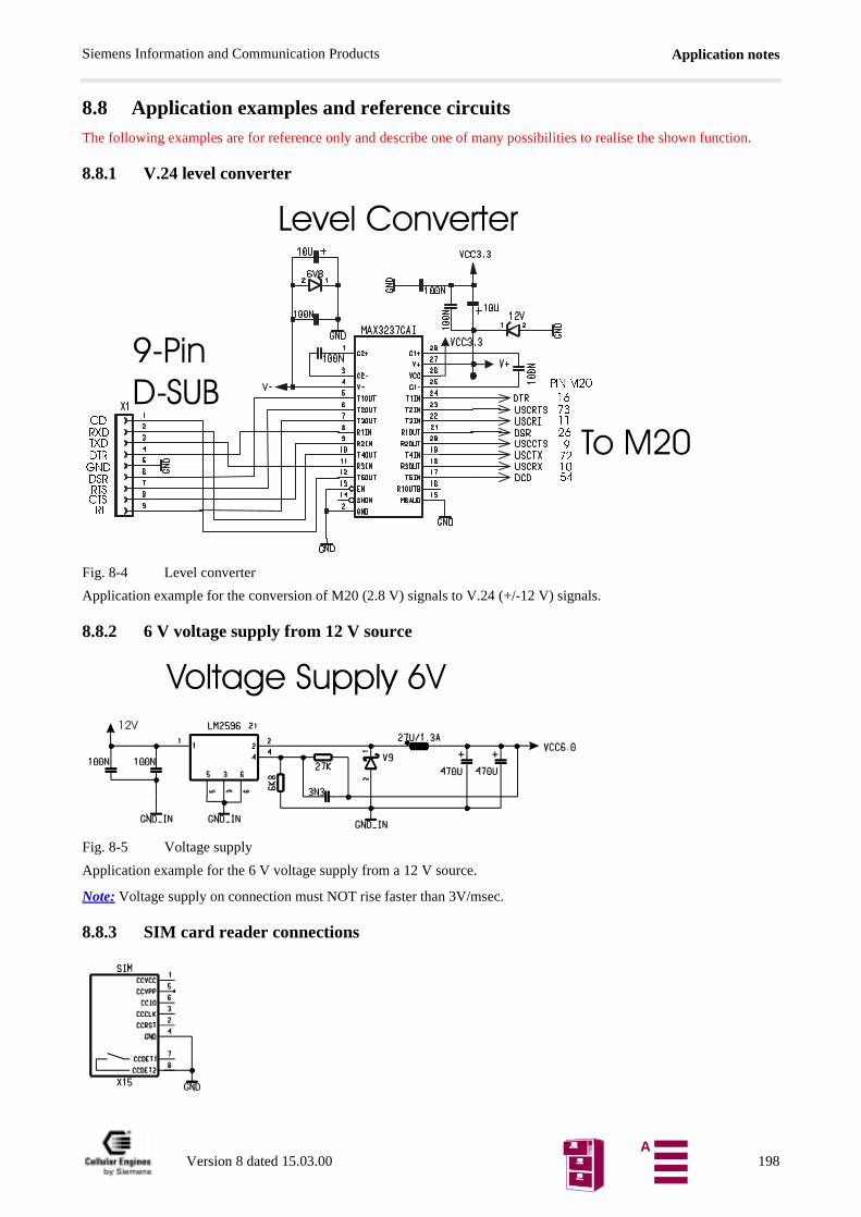
Application notesSiemens Information and Communication Products
8.8 Application examples and reference circuitsThe following examples are for reference only and describe one of many possibilities to realise the shown function.
8.8.1 V.24 level converter
Fig. 8-4 Level converter
Application example for the conversion of M20 (2.8 V) signals to V.24 (+/-12 V) signals.
8.8.2 6 V voltage supply from 12 V source
Fig. 8-5 Voltage supply
Application example for the 6 V voltage supply from a 12 V source.
Note: Voltage supply on connection must NOT rise faster than 3V/msec.
8.8.3 SIM card reader connections
/HYHO&RQYHUWHU
7R0
3LQ'68%
&'5;'7;''75*1''65576&765,
3,10
Version 8 dated 15.03.00 198A
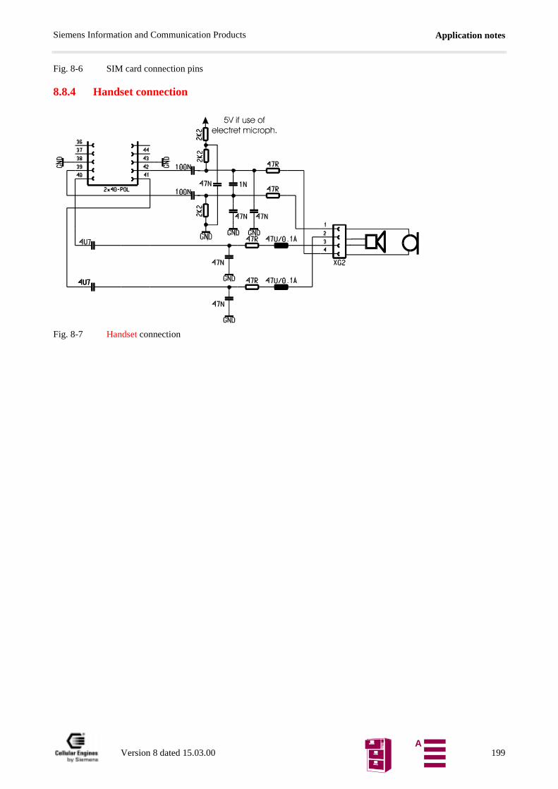
Application notesSiemens Information and Communication Products
Fig. 8-6 SIM card connection pins
8.8.4 Handset connection
Fig. 8-7 Handset connection
Version 8 dated 15.03.00 199A
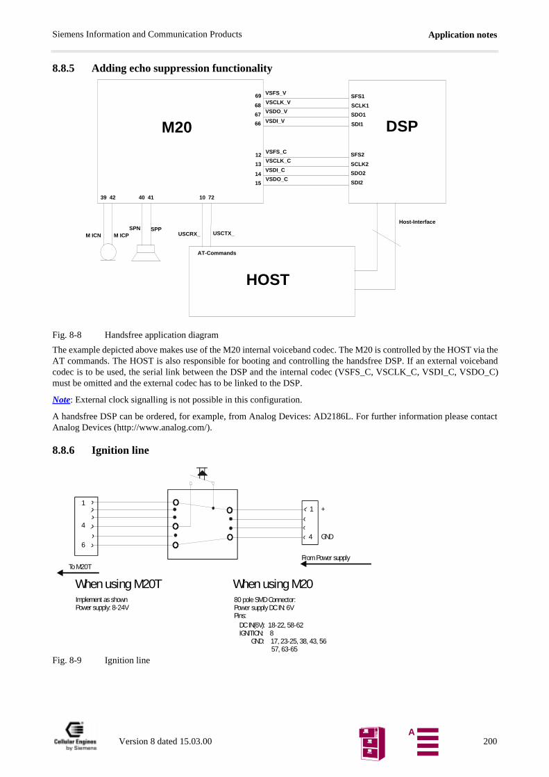
Application notesSiemens Information and Communication Products
8.8.5 Adding echo suppression functionality
Fig. 8-8 Handsfree application diagram
The example depicted above makes use of the M20 internal voiceband codec. The M20 is controlled by the HOST via theAT commands. The HOST is also responsible for booting and controlling the handsfree DSP. If an external voicebandcodec is to be used, the serial link between the DSP and the internal codec (VSFS_C, VSCLK_C, VSDI_C, VSDO_C)must be omitted and the external codec has to be linked to the DSP.
Note: External clock signalling is not possible in this configuration.
A handsfree DSP can be ordered, for example, from Analog Devices: AD2186L. For further information please contactAnalog Devices (http://www.analog.com/).
8.8.6 Ignition line
Fig. 8-9 Ignition line
69
68
67
66
12
13
14
15
VSFS_V
VSCLK_V
VSDI_V
VSDO_V
VSCLK_C
VSDI_C
VSDO_C
SFS1
SCLK1
SDO1
SDI1
SFS2
SCLK2
SDO2
SDI2
M20 DSP
39 42
M ICPM ICN
40 41
SPPSPN
10 72
USCTX_USCRX_
HOST
AT-Commands
Host-Interface
VSFS_C
GND
From Power supply
Implement as shownPower supply: 8-24V
80 pole SMD Connector:Power supply DC IN: 6VPins:
DC IN(6V): 18-22, 58-62IGNITION: 8 GND: 17, 23-25, 38, 43, 56 57, 63-65
To M20T
When using M20T When using M20
11
46
4
+
Version 8 dated 15.03.00 200A
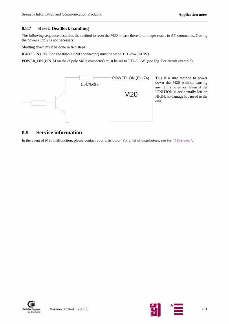
Application notesSiemens Information and Communication Products
8.8.7 Reset: Deadlock handling
The following sequence describes the method to reset the M20 in case there it no longer reacts to AT-commands. Cuttingthe power supply is not necessary.
Shutting down must be done in two steps:
IGNITION (PIN 8 on the 80pole SMD connector) must be set to TTL-low(<0.8V)
POWER_ON (PIN 74 on the 80pole SMD connector) must be set to TTL-LOW. (see Fig. For circuit example)
This is a sure method to powerdown the M20 without causingany faults or errors. Even if theIGNITION is accidentally left onHIGH, no damage is caused to theunit.
8.9 Service informationIn the event of M20 malfunction, please contact your distributor. For a list of distributors, see See “1 Overview”.
M20
POWER_ON (Pin 74)
1..4,7kOhm
Version 8 dated 15.03.00 201A
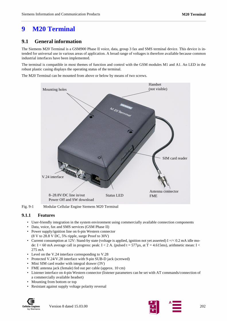
M20 TerminalSiemens Information and Communication Products
o-: I <
on of
9 M20 Terminal
9.1 General informationThe Siemens M20 Terminal is a GSM900 Phase II voice, data, group 3 fax and SMS terminal device. This device is in-tended for universal use in various areas of application. A broad range of voltages is therefore available because commonindustrial interfaces have been implemented.
The terminal is compatible in most themes of function and control with the GSM modules M1 and A1. An LED in therobust plastic casing displays the operating status of the terminal.
The M20 Terminal can be mounted from above or below by means of two screws.
Fig. 9-1 Modular Cellular Engine Siemens M20 Terminal
9.1.1 Features
• User-friendly integration in the system environment using commercially available connection components• Data, voice, fax and SMS services (GSM Phase II) • Power supply/ignition line on 6-pin Western connector
(8 V to 28.8 V DC, 5% ripple, surge Proof to 30V)• Current consumption at 12V: Stand-by state (voltage is applied, ignition not yet asserted) I =/< 0.2 mA idle m
de: I < 60 mA average call in progress: peak: I < 2 A. (pulsed t = 577µs, at T = 4.615ms), arithmetic mean275 mA
• Level on the V.24 interface corresponding to V.28• Protected V.24/V.28 interface with 9-pin SUB-D jack (screwed)• Mini SIM card reader with integral drawer (3V)• FME antenna jack (female) fed out per cable (approx. 10 cm) • Listener interface on 4-pin Western connector (listener parameters can be set with AT commands/connecti
a commercially available headset)• Mounting from bottom or top• Resistant against supply voltage polarity reversal
Mounting holesHandset(not visible)
Antenna connectorFME
SIM card reader
V.24 interface
8–28.8V/DC line in/outPower Off and SW download
Status LED
Version 8 dated 15.03.00 202A
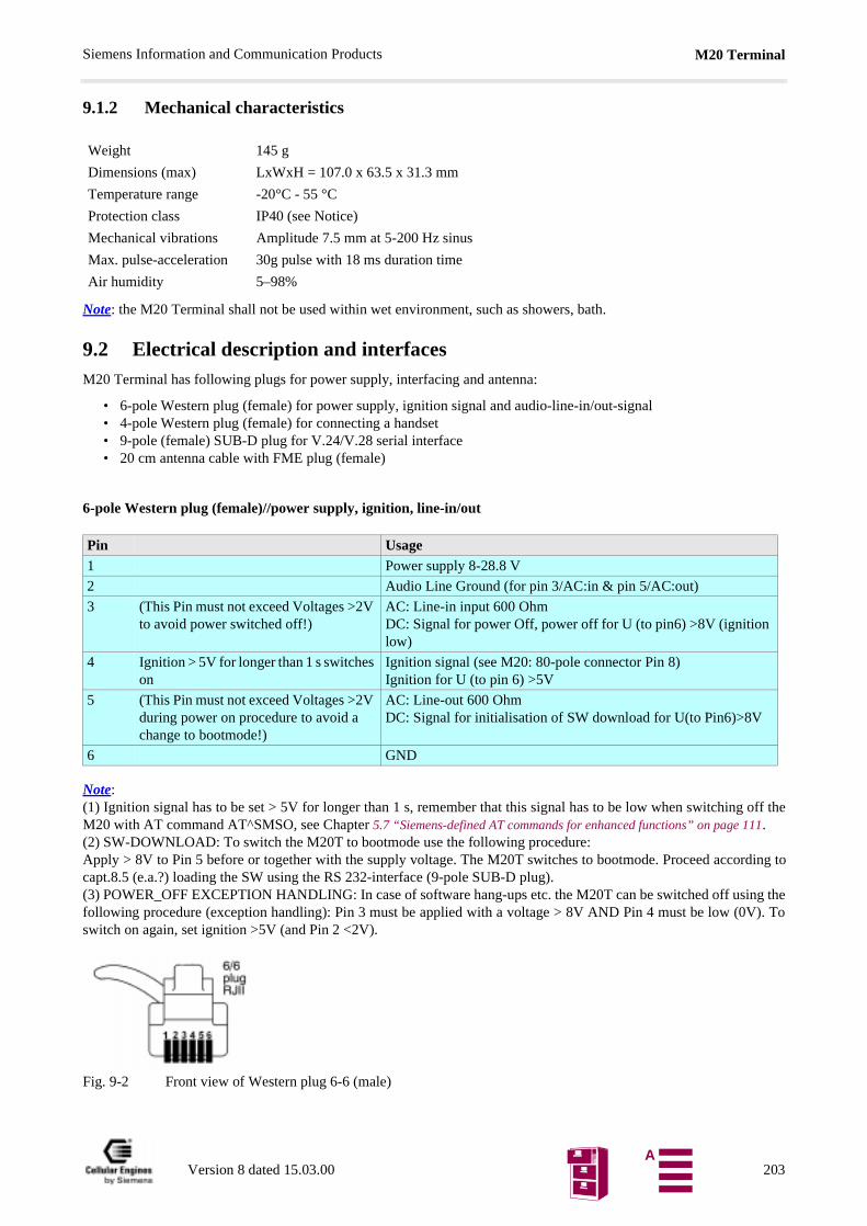
M20 TerminalSiemens Information and Communication Products
off the
9.1.2 Mechanical characteristics
Note: the M20 Terminal shall not be used within wet environment, such as showers, bath.
9.2 Electrical description and interfacesM20 Terminal has following plugs for power supply, interfacing and antenna:
• 6-pole Western plug (female) for power supply, ignition signal and audio-line-in/out-signal• 4-pole Western plug (female) for connecting a handset• 9-pole (female) SUB-D plug for V.24/V.28 serial interface• 20 cm antenna cable with FME plug (female)
6-pole Western plug (female)//power supply, ignition, line-in/out
Note:(1) Ignition signal has to be set > 5V for longer than 1 s, remember that this signal has to be low when switchingM20 with AT command AT^SMSO, see Chapter 5.7 “Siemens-defined AT commands for enhanced functions” on page 111.(2) SW-DOWNLOAD: To switch the M20T to bootmode use the following procedure:Apply > 8V to Pin 5 before or together with the supply voltage. The M20T switches to bootmode. Proceed according tocapt.8.5 (e.a.?) loading the SW using the RS 232-interface (9-pole SUB-D plug).(3) POWER_OFF EXCEPTION HANDLING: In case of software hang-ups etc. the M20T can be switched off using thefollowing procedure (exception handling): Pin 3 must be applied with a voltage > 8V AND Pin 4 must be low (0V). Toswitch on again, set ignition >5V (and Pin 2 <2V).
Fig. 9-2 Front view of Western plug 6-6 (male)
Weight 145 g
Dimensions (max) LxWxH = 107.0 x 63.5 x 31.3 mm
Temperature range -20°C - 55 °C
Protection class IP40 (see Notice)
Mechanical vibrations Amplitude 7.5 mm at 5-200 Hz sinus
Max. pulse-acceleration 30g pulse with 18 ms duration time
Air humidity 5–98%
Pin Usage1 Power supply 8-28.8 V
2 Audio Line Ground (for pin 3/AC:in & pin 5/AC:out)
3 (This Pin must not exceed Voltages >2V to avoid power switched off!)
AC: Line-in input 600 OhmDC: Signal for power Off, power off for U (to pin6) >8V (ignition low)
4 Ignition > 5V for longer than 1 s switches on
Ignition signal (see M20: 80-pole connector Pin 8)Ignition for U (to pin 6) >5V
5 (This Pin must not exceed Voltages >2V during power on procedure to avoid a change to bootmode!)
AC: Line-out 600 OhmDC: Signal for initialisation of SW download for U(to Pin6)>8V
6 GND
Version 8 dated 15.03.00 203A
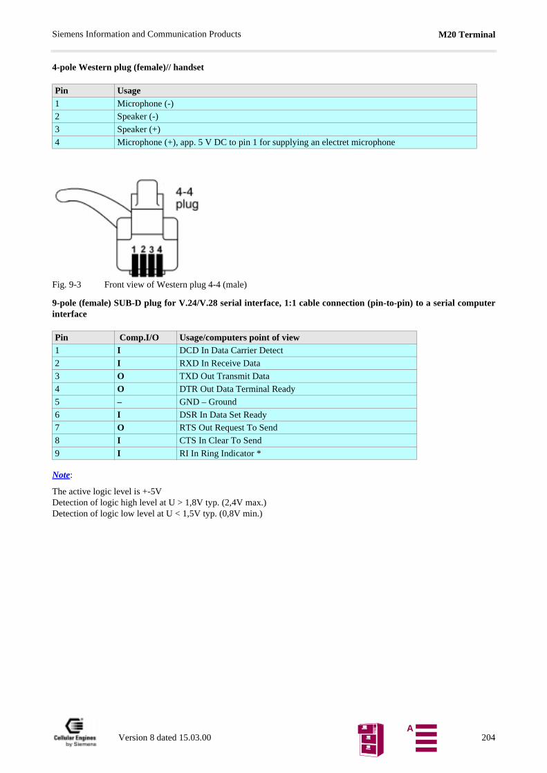
M20 TerminalSiemens Information and Communication Products
4-pole Western plug (female)// handset
Fig. 9-3 Front view of Western plug 4-4 (male)
9-pole (female) SUB-D plug for V.24/V.28 serial interface, 1:1 cable connection (pin-to-pin) to a serial computerinterface
Note:
The active logic level is +-5VDetection of logic high level at U > 1,8V typ. (2,4V max.)Detection of logic low level at U < 1,5V typ. (0,8V min.)
Pin Usage1 Microphone (-)
2 Speaker (-)
3 Speaker (+)
4 Microphone (+), app. 5 V DC to pin 1 for supplying an electret microphone
Pin Comp.I/O Usage/computers point of view1 I DCD In Data Carrier Detect
2 I RXD In Receive Data
3 O TXD Out Transmit Data
4 O DTR Out Data Terminal Ready
5 – GND – Ground
6 I DSR In Data Set Ready
7 O RTS Out Request To Send
8 I CTS In Clear To Send
9 I RI In Ring Indicator *
Version 8 dated 15.03.00 204A
M20 TerminalSiemens Information and Communication Products
he
0
Coding of the green status LED
Electrical characteristics
Note: Voltage supply: Voltage supply on connection must NOT rise faster than 3V/msec.
IMPORTANT: To protect to device against high voltage (>32V) a 1.25A quick-break fuse on pin 1 of the 6-pole Western plug shall beused. For use with power packs and batteries observe the EN60950 guidelines. Installation and start-up may only be per-formed by authorized persons.
LED Status Possible Error Checks & ActionsDark No power No power supply Check power supply
Check power cable pins
6-pole Western plug
pin 1: +, pin 6: GND
Blinking Power on &
Net searching
This status lasts longer than 1 minute after AT+CPIN="xxxx"
Check if SIM card is
inserted
Check if antenna cable is
correctly connected to FME plug
Check if antenna is correctly
positioned
Check if M20 IGNITION at Western plug has been set to logical high and Pin 3 of the 6-pole Western plug is applied with less than 4V DC
On Power on &
registered by the net
- -
Voltage range for correct operation 8(-0) to 28.8(+0) volts DC,
+/- 5% ripple
Voltage resistance without destruction 0–30 V (resistant against supply voltage polarity reversal)
Power cable <3m, use external "fast"-fuse 1,25 Ampere
Current consumption at 12V: Stand-by state (voltageis applied, ignition not yet asserted) I =/< 0.2 mA idlemode: I < 60 mA average call in progress: peak: I <2 A. (pulsed t = 577ms, at T = 4.615ms), arithmeticmean: I < 275 mA
<200mA speech mode, <45mA idle mode
Mini SIM reader For 3 V mini SIM cardsNote: SIM cards should only be inserted and removed when tterminal is OFF
Line-in 600 Ohm (differential mode)
Line-out 600 Ohm (common mode)
V.24 interface Double-diode protection,
150 Ohm current limiter
Max. modem cable length for correct operation Length < 2 m
Max. handset cable length Length < 2 m
Antenna plug FME female,
Further electrical specifications (power, sensitivity, etc.) see M2Cellular Engine
Max. RF power 2 W at 900 MHz
Handset plug with 5V supply for electret microphone
Spark-gap protection
Version 8 dated 15.03.00 205A

M20 TerminalSiemens Information and Communication Products
9.3 Operation requirements, CE conformity, restrictions of useFor operation requirements, see Chapter 3.5 “System requirements” on page 15, for CE conformity, see Chapter 3.6 “CE con-formity” on page 15.
For safety instructions, see Chapter 2 “Safety precautions for the user” on page 8.
9.4 Full-type approvalIn reference to the approval requirements for M20 Terminal configurations, the following points must be observed:
1) No further approvals are required for application when using the M20 Terminal in approved configurations. Delta-type approval is necessary if any accessories (handset, own MMI implementation supported by AT commands) other than the approved accessories are used. Information about approved configurations and accessories that have been approved for use with the M20 Terminal can be obtained in the appendix to EC TYPE EXAMINATION CERTIFI-CATE or from your local distributor.
2) Applications using the "DATA ONLY" capabilities (data, SMS, fax) of the M20 Terminal need no further delta-type approval.
Version 8 dated 15.03.00 206A
M20 Development BoxSiemens Information and Communication Products
au-and
and testr on the
t conditi-
ter
10 M20 Development BoxThe M20 Development Box was developed as a variant of M20 Terminal for developing and testing own applications withM20 Cellular Engine. The Development Box has almost the same functionality as the M20 Terminal with following ad-ditional features:
• On-board male pins for each relevant pin of M20 80-pole connector not used by M20 Terminal (e.g. digital dio interface, keyport interface, display interface), the connection to customers application might be with bcables.
Note: Protection class IP40 can not be guaranteed for this variant.
• Male pins for application of other SIM card readers
The configuration of the additional pins is delivered with this product.
The A20 d-box is available from your local Distributor. Please note that the D-box is to be used for Development- purposes only, and that deviating from the general terms of delivery no responsibility or guarantee is taken ovepart of Siemens AG. Please contact your local distributor.
11 Environmental requirements for the M20The applicable standards and internal and customer-specific supplementary requirements with regard to ambienons for the M20 are in accordance to IEC68.
12 EMC and ESD requirementsStandard ETS 300 342-1 dated 06/97 applies to the M20 as regards EMC and ESD requirements.
Additional requirements with regard to EMC/ESD:• An EMC-filtered power supply must be made available to the M20 via the base unit.
When the M20 is used in vehicles, the requirements of standard ETS 300 342-1 dated 06/97, Section 9.5 mustbe satisfied with regard to the power supply.
• When using the M20 with individual handsfree kits, the possibility of susceptibility problems exists.
• For additional EMC-relevant information (e.g. maximum length of connecting lines and shielding), see ChapEMC-relevant information for integrators of the M20.
13 Migration M1 to M20Applications using the M1 can be updated for use with the M20.
Following changes in the area of SW need to be taken into account.
13.1 SW comparison
13.1.1 SMS mode
The M1 offered only PDU SMS, on the M20 Text and PDU is available, (AT+CMGF)
Changes when creating PDU mode strings with the M20.
In the M1 the value for the UDL (User data length) could be set to any value larger the real data length.
In the M20 the value for UDL has to be the EXACT length of the user Data
Version 8 dated 15.03.00 207A
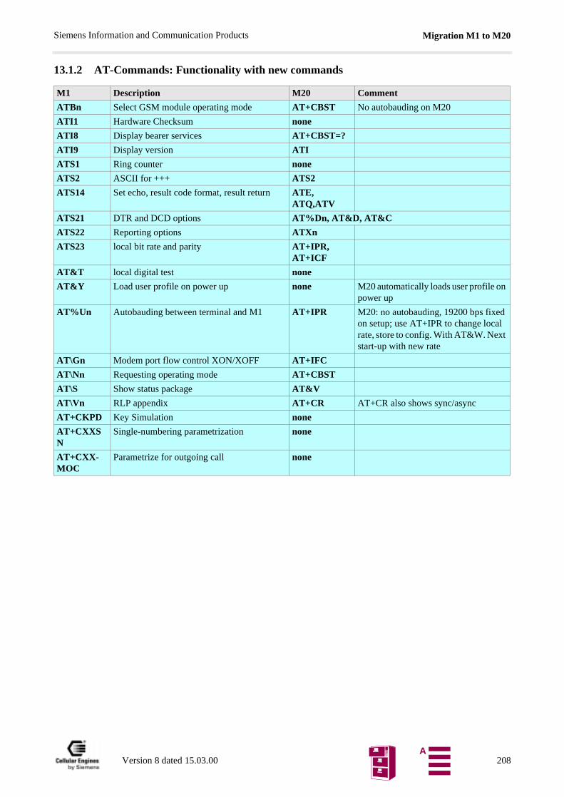
Migration M1 to M20Siemens Information and Communication Products
13.1.2 AT-Commands: Functionality with new commands
M1 Description M20 Comment
ATBn Select GSM module operating mode AT+CBST No autobauding on M20
ATI1 Hardware Checksum none
ATI8 Display bearer services AT+CBST=?
ATI9 Display version ATI
ATS1 Ring counter none
ATS2 ASCII for +++ ATS2
ATS14 Set echo, result code format, result return ATE, ATQ,ATV
ATS21 DTR and DCD options AT%Dn, AT&D, AT&C
ATS22 Reporting options ATXn
ATS23 local bit rate and parity AT+IPR, AT+ICF
AT&T local digital test none
AT&Y Load user profile on power up none M20 automatically loads user profile on power up
AT%Un Autobauding between terminal and M1 AT+IPR M20: no autobauding, 19200 bps fixed on setup; use AT+IPR to change local rate, store to config. With AT&W. Next start-up with new rate
AT\Gn Modem port flow control XON/XOFF AT+IFC
AT\Nn Requesting operating mode AT+CBST
AT\S Show status package AT&V
AT\Vn RLP appendix AT+CR AT+CR also shows sync/async
AT+CKPD Key Simulation none
AT+CXXSN
Single-numbering parametrization none
AT+CXX-MOC
Parametrize for outgoing call none
Version 8 dated 15.03.00 208A
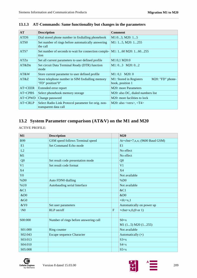
Migration M1 to M20Siemens Information and Communication Products
13.1.3 AT-Commands: Same functionality but changes in the parameters
13.2 System Parameter comparison (AT&V) on the M1 and M20ACTIVE PROFILE:
AT Description Comment
ATDS Dial stored phone number in fixdialling phonebook M1:0...3, M20: 1...5
ATS0 Set number of rings before automatically answering the call
M1: 1...5, M20: 1...255
ATS7 Set number of seconds to wait for connection comple-tion
M1: 1...60 M20: 1...60...255
ATZn Set all current parameters to user defined profile M1:0,1 M20:0
AT&Dn Set circuit Data Terminal Ready (DTR) function mode
M1: 0...3 M20: 0...2
AT&W Store current parameter to user defined profile M1: 0,1 M20: 0
AT&Z Store telephone number in SIM fixdialling memory "FD" position"0"
M1: Stored in Registers M20: "FD" phone-book, position 1
AT+CEER Extended error report M20: more Parameters
AT+CPBS Select phonebook memory storage M20: also DC, dialed numbers list
AT+CPWD Change password M20: more facilities to lock
AT+CRLP Select Radio Link Protocol parameter for orig. non-transparent data call
M20: also <verx>, <T4>
M1 Description M20
B99 GSM speed follows Terminal speed At+cbst=7,x,x; (9600 Baud GSM)
E1 Set Command Echo mode E1
L2 No effect
M1 No effect
Q0 Set result code presentation mode Q0
V1 Set result code format V1
X4 X4
Y0 Not available
%D0 Auto FDN0 dialling %D0
%U0 Autobauding serial Interface Not available
&C1 &C1
&D0 &D0
&G0 +ifc=x,1
&Y0 Set user parameters Automatically on power up
\N0 RLP on/off F +cbst=x,0,(0 or 1)
S00:000 Number of rings before answering call S0=x
M1 (1...5) M20 (1...255)
S01:000 Ring counter Not available
S02:043 Escape sequence Character Automatically (+)
S03:013 S3=x
S04:010 S4=x
S05:008 S5=x
Version 8 dated 15.03.00 209A
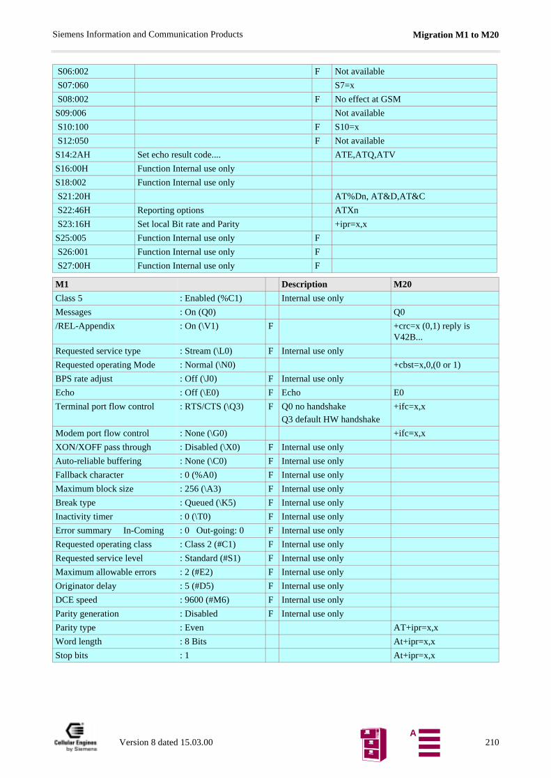
Migration M1 to M20Siemens Information and Communication Products
S06:002 F Not available
S07:060 S7=x
S08:002 F No effect at GSM
S09:006 Not available
S10:100 F S10=x
S12:050 F Not available
S14:2AH Set echo result code.... ATE,ATQ,ATV
S16:00H Function Internal use only
S18:002 Function Internal use only
S21:20H AT%Dn, AT&D,AT&C
S22:46H Reporting options ATXn
S23:16H Set local Bit rate and Parity +ipr=x,x
S25:005 Function Internal use only F
S26:001 Function Internal use only F
S27:00H Function Internal use only F
M1 Description M20
Class 5 : Enabled (%C1) Internal use only
Messages : On (Q0) Q0
/REL-Appendix : On (\V1) F +crc=x (0,1) reply is V42B...
Requested service type : Stream (\L0) F Internal use only
Requested operating Mode : Normal (\N0) +cbst=x,0,(0 or 1)
BPS rate adjust : Off (\J0) F Internal use only
Echo : Off (\E0) F Echo E0
Terminal port flow control : RTS/CTS (\Q3) F Q0 no handshake
Q3 default HW handshake
+ifc=x,x
Modem port flow control : None (\G0) +ifc=x,x
XON/XOFF pass through : Disabled (\X0) F Internal use only
Auto-reliable buffering : None (\C0) F Internal use only
Fallback character : 0 (%A0) F Internal use only
Maximum block size : 256 (\A3) F Internal use only
Break type : Queued (\K5) F Internal use only
Inactivity timer : 0 (\T0) F Internal use only
Error summary In-Coming : 0 Out-going: 0 F Internal use only
Requested operating class : Class 2 (#C1) F Internal use only
Requested service level : Standard (#S1) F Internal use only
Maximum allowable errors : 2 (#E2) F Internal use only
Originator delay : 5 (#D5) F Internal use only
DCE speed : 9600 (#M6) F Internal use only
Parity generation : Disabled F Internal use only
Parity type : Even AT+ipr=x,x
Word length : 8 Bits At+ipr=x,x
Stop bits : 1 At+ipr=x,x
Version 8 dated 15.03.00 210A
ReferencesSiemens Information and Communication Products
14 References[1] ETS 300 607-2: October 1996 (GSM 11.10-2 Version 4.15.0)
[2] ETS 300 511: July 1995 (GSM 2.30 Version 4.13.0)
[3] V.24 (ITU-T, V.24, 10/96)
[4] V.28 (ITU-T recommendations, CD-ROM March 1998)
[5] V.25ter (ITU-T, V.25ter, 07/97)
[6] ETS 300 342 (ETSI – June 1997, second edition)
[7] TBR19 (ETSI – CD-ROM A, July 1998)
[8] TBR20 (ETSI – CD-ROM A, July 1998)
Version 8 dated 15.03.00 211A
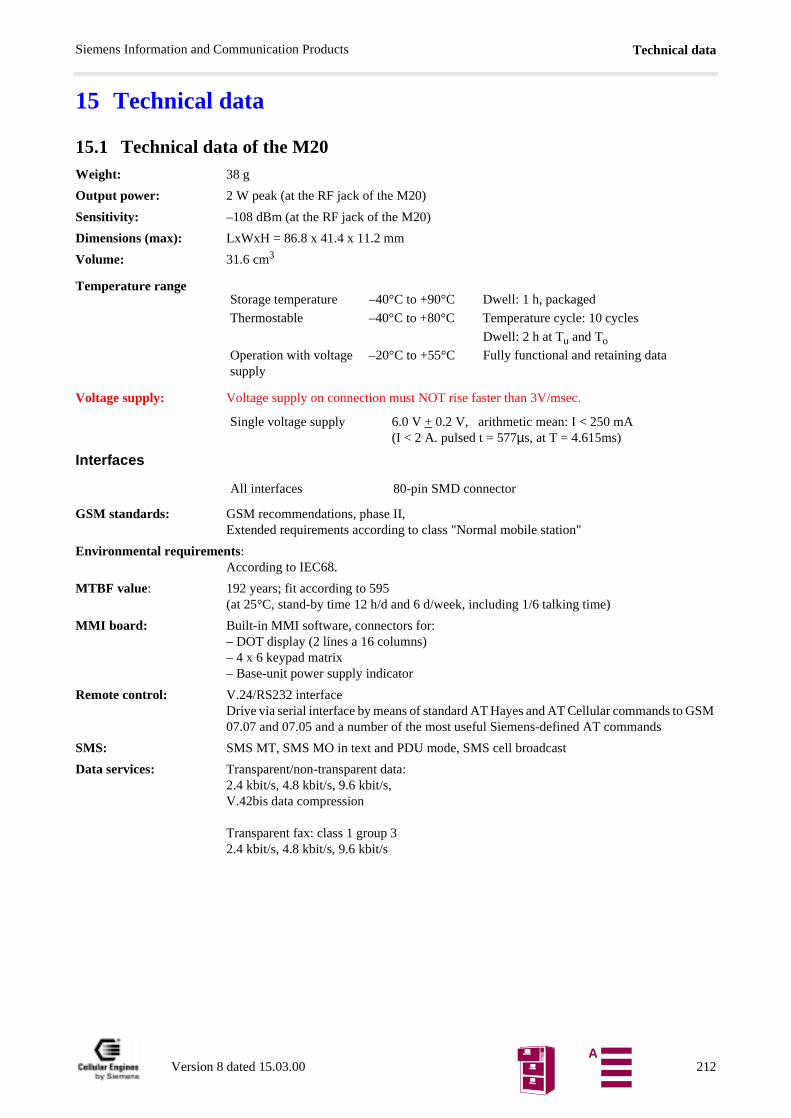
Technical dataSiemens Information and Communication Products
GSM
15 Technical data
15.1 Technical data of the M20Weight: 38 g
Output power: 2 W peak (at the RF jack of the M20)
Sensitivity: –108 dBm (at the RF jack of the M20)
Dimensions (max): LxWxH = 86.8 x 41.4 x 11.2 mm
Volume: 31.6 cm3
Temperature range
Voltage supply: Voltage supply on connection must NOT rise faster than 3V/msec.
Interfaces
GSM standards: GSM recommendations, phase II,Extended requirements according to class "Normal mobile station"
Environmental requirements:According to IEC68.
MTBF value: 192 years; fit according to 595(at 25°C, stand-by time 12 h/d and 6 d/week, including 1/6 talking time)
MMI board: Built-in MMI software, connectors for:– DOT display (2 lines a 16 columns)– 4 x 6 keypad matrix– Base-unit power supply indicator
Remote control: V.24/RS232 interfaceDrive via serial interface by means of standard AT Hayes and AT Cellular commands to 07.07 and 07.05 and a number of the most useful Siemens-defined AT commands
SMS: SMS MT, SMS MO in text and PDU mode, SMS cell broadcast
Data services: Transparent/non-transparent data:2.4 kbit/s, 4.8 kbit/s, 9.6 kbit/s, V.42bis data compression
Transparent fax: class 1 group 32.4 kbit/s, 4.8 kbit/s, 9.6 kbit/s
Storage temperature –40°C to +90°C Dwell: 1 h, packaged
Thermostable –40°C to +80°C Temperature cycle: 10 cycles
Dwell: 2 h at Tu and To
Operation with voltage supply
–20°C to +55°C Fully functional and retaining data
Single voltage supply 6.0 V + 0.2 V, arithmetic mean: I < 250 mA(I < 2 A. pulsed t = 577µs, at T = 4.615ms)
All interfaces 80-pin SMD connector
Version 8 dated 15.03.00 212A
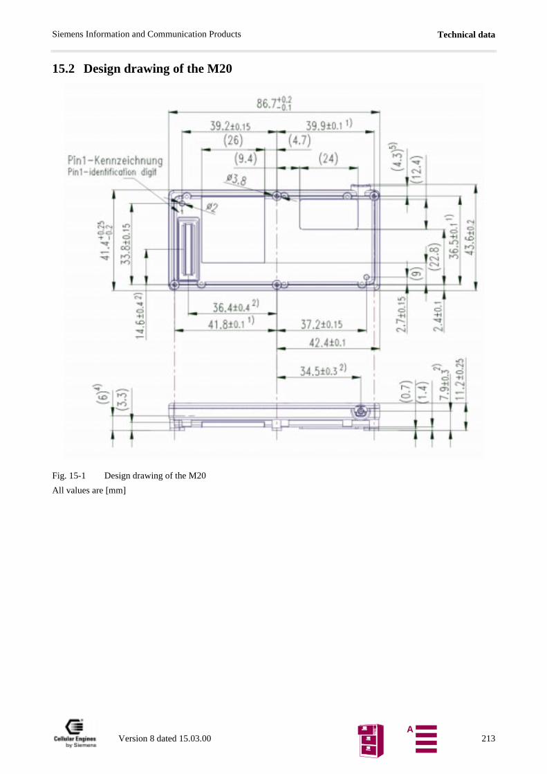
Technical dataSiemens Information and Communication Products
15.2 Design drawing of the M20
Fig. 15-1 Design drawing of the M20
All values are [mm]
Version 8 dated 15.03.00 213A
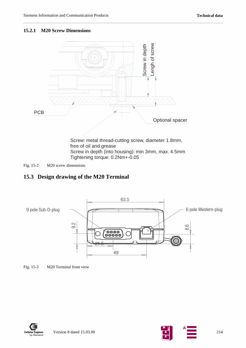
Technical dataSiemens Information and Communication Products
15.2.1 M20 Screw Dimensions
Fig. 15-2 M20 screw dimensions
15.3 Design drawing of the M20 Terminal
Fig. 15-3 M20 Terminal front view
Screw: metal thread-cutting screw, diameter 1.8mm,free of oil and greaseScrew in depth (into housing): min 3mm, max. 4.5mmTightening torque: 0.2Nm+-0.05
Optional spacer
PCB
Scr
ew in
dep
th
Leng
h of
scr
ew
Version 8 dated 15.03.00 214A
Technical dataSiemens Information and Communication Products
Fig. 15-4 M20 Terminal back view
Fig. 15-5 M20 Terminal top and side view
Version 8 dated 15.03.00 215A
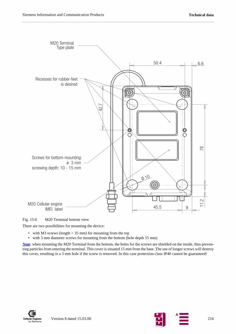
Technical dataSiemens Information and Communication Products
preven- destroyteed!
Fig. 15-6 M20 Terminal bottom view
There are two possibilities for mounting the device:
• with M3 screws (length > 35 mm) for mounting from the top• with 3 mm diameter screws for mounting from the bottom (hole depth 15 mm)
Note: when mounting the M20 Terminal from the bottom, the holes for the screws are shielded on the inside, thusting particles from entering the terminal. This cover is situated 15 mm from the base. The use of longer screws willthis cover, resulting in a 3 mm hole if the screw is removed. In this case protection-class IP40 cannot be guaran
Version 8 dated 15.03.00 216A
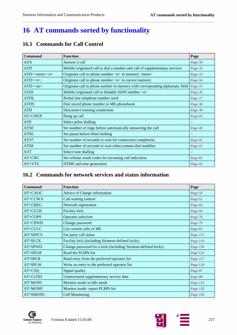
AT commands sorted by functionalitySiemens Information and Communication Products
16 AT commands sorted by functionality
16.1 Commands for Call Control
16.2 Commands for network services and status information
Command Function Page
ATA Answer a call Page 30
ATD Mobile originated call to dial a number and call of supplementary services Page 30
ATD><mem><n> Originate call to phone number <n> in memory <mem> Page 33
ATD><n>; Originate call to phone number <n> in current memory Page 34
ATD><str> Originate call to phone number in memory with corresponding alphanum. field Page 35
ATDI Mobile originated call to dialable ISDN number <n> Page 36
ATDL Redial last telephone number used Page 37
ATDS Dial stored phone number in ME-phonebook Page 38
ATH Disconnect existing connection Page 38
AT+CHUP Hang up call Page 64
ATP Select pulse dialling –
ATS0 Set number of rings before automatically answering the call Page 40
ATS6 Set pause before blind dialling –
ATS7 Set number of seconds to wait for connection completion Page 41
ATS8 Set number of seconds to wait when comma dial modifier Page 41
ATT Select tone dialling –
AT+CRC Set cellular result codes for incoming call indication Page 82
AT+VTS DTMF and tone generation Page 92
Command Function Page
AT+CAOC Advice of Charge information Page 58
AT+CCWA Call waiting control Page 62
AT+CREG Network registration Page 84
AT+CLCK Facility lock Page 66
AT+COPS Operator selection Page 70
AT+CPWD Change password Page 79
AT+CLCC List current calls of ME Page 65
AT^SFPCS Far party call status Page 115
AT^SLCK Facility lock (including Siemens-defined locks) Page 116
AT^SPWD Change password for a lock (including Siemens-defined locks) Page 130
AT^SPLM Read the PLMN list Page 126
AT^SPLR Read entry from the preferred operator list Page 127
AT^SPLW Write an entry to the preferred operator list Page 128
AT+CSQ Signal quality Page 87
AT+CUSD Unstructured supplementary service data Page 88
AT^MONI Monitor mode in Idle mode Page 133
AT^MONP Monitor mode: report PLMN list Page 135
AT^SMONC Cell Monitoring Page 136
Version 8 dated 15.03.00 217A
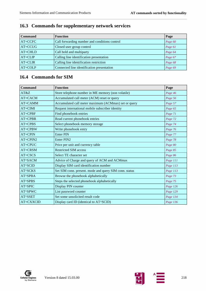
AT commands sorted by functionalitySiemens Information and Communication Products
16.3 Commands for supplementary network services
16.4 Commands for SIM
Command Function Page
AT+CCFC Call forwarding number and conditions control Page 60
AT+CCUG Closed user group control Page 61
AT+CHLD Call hold and multiparty Page 64
AT+CLIP Calling line identification presentation Page 67
AT+CLIR Calling line identification restriction Page 68
AT+COLP Connected line identification presentation Page 69
Command Function Page
AT&Z Store telephone number in ME memory (non volatile) Page 46
AT+CACM Accumulated call meter (ACM) reset or query Page 56
AT+CAMM Accumulated call meter maximum (ACMmax) set or query Page 57
AT+CIMI Request international mobile subscriber identity Page 65
AT+CPBF Find phonebook entries Page 71
AT+CPBR Read current phonebook entries Page 72
AT+CPBS Select phonebook memory storage Page 74
AT+CPBW Write phonebook entry Page 76
AT+CPIN Enter PIN Page 77
AT+CPIN2 Enter PIN2 Page 78
AT+CPUC Price per unit and currency table Page 80
AT+CRSM Restricted SIM access Page 85
AT+CSCS Select TE character set Page 86
AT^SACM Advice of Charge and query of ACM and ACMmax Page 111
AT^SCID Display SIM card identification number Page 113
AT^SCKS Set SIM conn. present. mode and query SIM conn. status Page 113
AT^SPBA Browse the phonebook alphabetically Page 73
AT^SPBS Steps the selected phonebook alphabetically Page 75
AT^SPIC Display PIN counter Page 126
AT^SPWC List password counter Page 129
AT^SSET Set some unsolicited result code Page 134
AT+CXXCID Display card ID (identical to AT^SCID) Page 136
Version 8 dated 15.03.00 218A
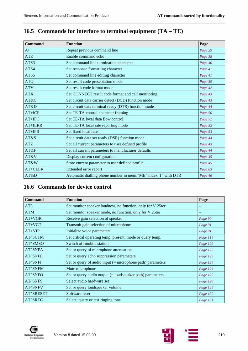
AT commands sorted by functionalitySiemens Information and Communication Products
16.5 Commands for interface to terminal equipment (TA – TE)
16.6 Commands for device control
Command Function Page
A/ Repeat previous command line Page 29
ATE Enable command echo Page 38
ATS3 Set command line termination character Page 40
ATS4 Set response formatting character Page 41
ATS5 Set command line editing character Page 41
ATQ Set result code presentation mode Page 39
ATV Set result code format mode Page 42
ATX Set CONNECT result code format and call monitoring Page 43
AT&C Set circuit data carrier detect (DCD) function mode Page 43
AT&D Set circuit data terminal ready (DTR) function mode Page 44
AT+ICF Set TE-TA control character framing Page 50
AT+IFC Set TE-TA local data flow control Page 51
AT+ILRR Set TE-TA local rate reporting mode Page 52
AT+IPR Set fixed local rate Page 53
AT&S Set circuit data set ready (DSR) function mode Page 44
ATZ Set all current parameters to user defined profile Page 43
AT&F Set all current parameters to manufacturer defaults Page 44
AT&V Display current configuration Page 45
AT&W Store current parameter to user defined profile Page 45
AT+CEER Extended error report Page 63
AT%D Automatic dialling phone number in mem.”ME” index”1” with DTR Page 46
Command Function Page
ATL Set monitor speaker loudness, no function, only for V.25ter –
ATM Set monitor speaker mode, no function, only for V.25ter –
AT+VGR Receive gain selection of speaker Page 90
AT+VGT Transmit gain selection of microphone Page 91
AT+VIP Initialize voice parameters Page 91
AT^SCTM Set critical operating temp. present. mode or query temp. Page 114
AT^SMSO Switch off mobile station Page 122
AT^SNFA Set or query of microphone attenuation Page 122
AT^SNFE Set or query echo suppression parameters Page 123
AT^SNFI Set or query of audio input (= microphone path) parameters Page 124
AT^SNFM Mute microphone Page 124
AT^SNFO Set or query audio output (= loudspeaker path) parameters Page 125
AT^SNFS Select audio hardware set Page 126
AT^SNFV Set or query loudspeaker volume Page 126
AT^SRESET Software reset Page 130
AT^SRTC Select, query or test ringing tone Page 131
Version 8 dated 15.03.00 219A
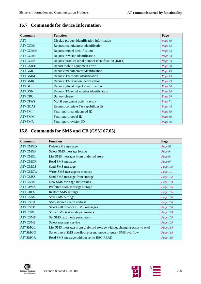
AT commands sorted by functionalitySiemens Information and Communication Products
16.7 Commands for device Information
16.8 Commands for SMS and CB (GSM 07.05)
Command Function Page
ATI Display product identification information Page 39
AT+CGMI Request manufacturer identification Page 63
AT+CGMM Request model identification Page 63
AT+CGMR Request revision identification Page 63
AT+CGSN Request product serial number identification (IMEI) Page 64
AT+CMEE Report mobile equipment error Page 68
AT+GMI Request manufacturer identification Page 49
AT+GMM Request TA model identification Page 49
AT+GMR Request TA revision identification Page 49
AT+GOI Request global object identification Page 50
AT+GSN Request TA serial number identification Page 50
AT+CBC Battery charge Page 58
AT+CPAS Mobil equipment activity status Page 71
AT+GCAP Request complete TA capabilities list Page 48
AT+FMI Fax: report manufactured ID Page 89
AT+FMM Fax: report model ID Page 89
AT+FMR Fax: report revision ID Page 90
Command Function Page
AT+CMGD Delete SMS message Page 93
AT+CMGF Select SMS message format Page 94
AT+CMGL List SMS messages from preferred store Page 94
AT+CMGR Read SMS message Page 97
AT+CMGS Send SMS message Page 100
AT+CMGW Write SMS message to memory Page 101
AT+CMSS Send SMS message from storage Page 102
AT+CNMI New SMS message indications Page 103
AT+CPMS Preferred SMS message storage Page 105
AT+CRES Restore SMS settings Page 105
AT+CSAS Save SMS settings Page 106
AT+CSCA SMS service centre address Page 106
AT+CSCB Select cell broadcast SMS messages Page 106
AT+CSDH Show SMS text mode parameters Page 108
AT+CSMP Set SMS text mode parameters Page 109
AT+CSMS Select message service Page 109
AT^SMGL List SMS messages from preferred storage without changing status to read Page 118
AT^SMGO Set or query SMS overflow present. mode or query SMS overflow Page 118
AT^SMGR Read SMS message without set to REC READ Page 119
Version 8 dated 15.03.00 220A
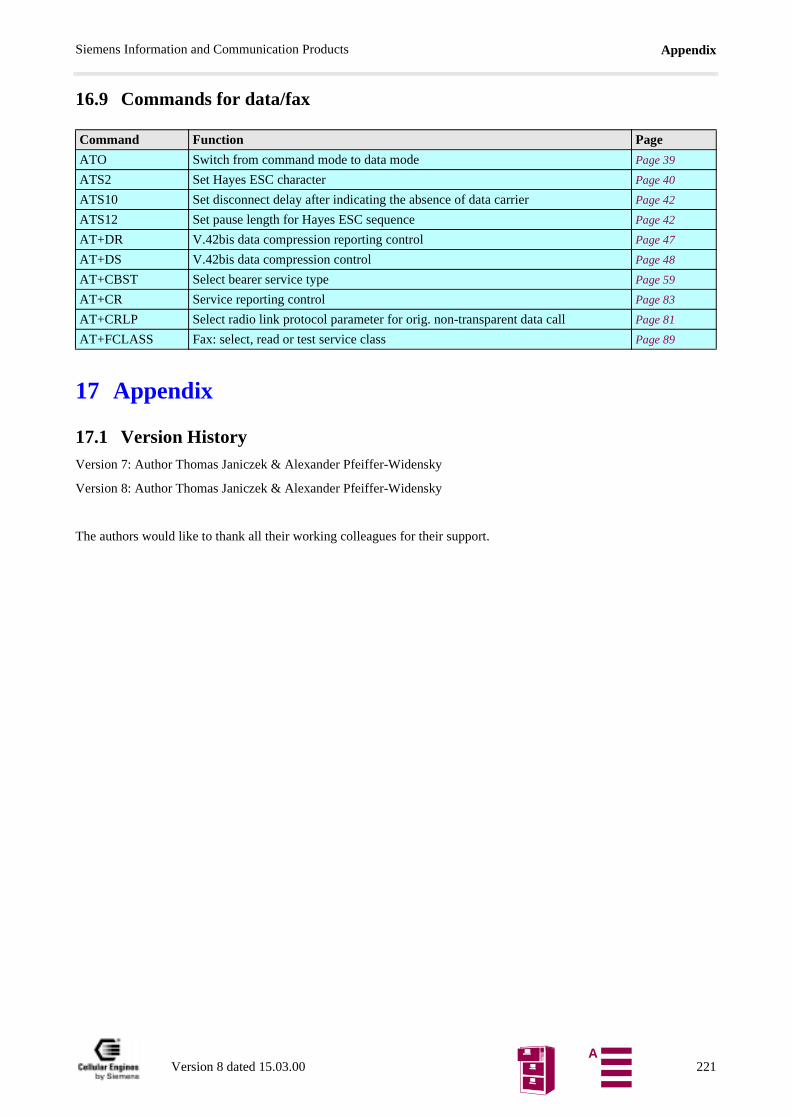
AppendixSiemens Information and Communication Products
16.9 Commands for data/fax
17 Appendix
17.1 Version HistoryVersion 7: Author Thomas Janiczek & Alexander Pfeiffer-Widensky
Version 8: Author Thomas Janiczek & Alexander Pfeiffer-Widensky
The authors would like to thank all their working colleagues for their support.
Command Function Page
ATO Switch from command mode to data mode Page 39
ATS2 Set Hayes ESC character Page 40
ATS10 Set disconnect delay after indicating the absence of data carrier Page 42
ATS12 Set pause length for Hayes ESC sequence Page 42
AT+DR V.42bis data compression reporting control Page 47
AT+DS V.42bis data compression control Page 48
AT+CBST Select bearer service type Page 59
AT+CR Service reporting control Page 83
AT+CRLP Select radio link protocol parameter for orig. non-transparent data call Page 81
AT+FCLASS Fax: select, read or test service class Page 89
Version 8 dated 15.03.00 221A

Siemens Information and Communication Products
AT command summary
(pause)+++(pause) ESC from data mode to command mode .......................................................29A/ Repeat previous command line ......................................................................29AT%D Automatic dialling phone number in mem. "ME" index "1" with DTR ........46AT&C Set circuit Data Carrier Detect (DCD) function mode ...................................43AT&D Set circuit Data Terminal Ready (DTR) function mode ................................44AT&F Set all current parameters to manufacturer defaults .......................................44AT&S Set circuit Data Set Ready (DSR) function mode ..........................................44AT&V Display current configuration ........................................................................45AT&W Store current parameter to user defined profile .............................................45AT&Z Store telephone number in SIM fixdialling memory "FD" ............................46AT+CACM Accumulated call meter (ACM) reset or query ..............................................56AT+CAMM Accumulated call meter maximum (ACMmax) set or query .........................57AT+CAOC Advice of Charge information .......................................................................58AT+CBC Battery charge ................................................................................................58AT+CBST Select Bearer Service Type ............................................................................59AT+CCFC Call forwarding number and conditions control ............................................60AT+CCUG Closed user group control ..............................................................................61AT+CCWA Call waiting control ........................................................................................62AT+CEER Extended error report .....................................................................................63AT+CGMI Request manufacturer identification ..............................................................63AT+CGMM Request model identification .........................................................................63AT+CGMR Request revision identification of software status .........................................63AT+CGSN Request product serial number identification (IMEI) identical to GSN ........64AT+CHLD Call hold and multiparty ................................................................................64AT+CHUP Hang up call ...................................................................................................64AT+CIMI Request international mobile subscriber identity ...........................................65AT+CLCC List current calls of ME .................................................................................65AT+CLCK Facility lock ....................................................................................................66AT+CLIP Calling line identification presentation ..........................................................67AT+CLIR Calling line identification restriction .............................................................68AT+CMEE Report mobile equipment error ......................................................................68AT+CMGD Delete SMS message ......................................................................................93AT+CMGF Select SMS message format ...........................................................................94AT+CMGL List SMS messages from preferred store .......................................................94AT+CMGR Read SMS message ........................................................................................97AT+CMGS Send SMS message ......................................................................................100AT+CMGW Write SMS message to memory ...................................................................101AT+CMSS Send SMS message from storage .................................................................102AT+CNMI New SMS message indications ....................................................................103AT+COLP Connected line identification presentation .....................................................69AT+COPS Operator selection ..........................................................................................70AT+CPAS Mobile equipment activity status ...................................................................71AT+CPBF Find phonebook entries ..................................................................................71AT+CPBR Read current phonebook entries .....................................................................72AT+CPBS Select phonebook memory storage ................................................................74AT+CPBW Write phonebook entry ...................................................................................76AT+CPIN Enter PIN ........................................................................................................77AT+CPIN2 Enter PIN2 ......................................................................................................78
Version 8 dated 15.03.00 221A
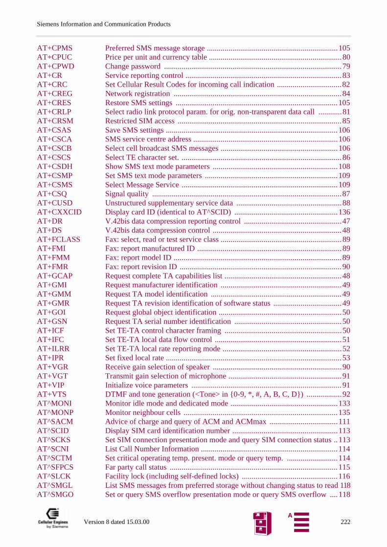
Siemens Information and Communication Products
AT+CPMS Preferred SMS message storage ...................................................................105AT+CPUC Price per unit and currency table ....................................................................80AT+CPWD Change password ...........................................................................................79AT+CR Service reporting control ................................................................................83AT+CRC Set Cellular Result Codes for incoming call indication .................................82AT+CREG Network registration ......................................................................................84AT+CRES Restore SMS settings ...................................................................................105AT+CRLP Select radio link protocol param. for orig. non-transparent data call ............81AT+CRSM Restricted SIM access ....................................................................................85AT+CSAS Save SMS settings ........................................................................................106AT+CSCA SMS service centre address ..........................................................................106AT+CSCB Select cell broadcast SMS messages ............................................................106AT+CSCS Select TE character set. ..................................................................................86AT+CSDH Show SMS text mode parameters ................................................................108AT+CSMP Set SMS text mode parameters ....................................................................109AT+CSMS Select Message Service ................................................................................109AT+CSQ Signal quality .................................................................................................87AT+CUSD Unstructured supplementary service data ......................................................88AT+CXXCID Display card ID (identical to AT^SCID) .....................................................136AT+DR V.42bis data compression reporting control ..................................................47AT+DS V.42bis data compression control ..................................................................48AT+FCLASS Fax: select, read or test service class ..............................................................89AT+FMI Fax: report manufactured ID ..........................................................................89AT+FMM Fax: report model ID ......................................................................................89AT+FMR Fax: report revision ID ...................................................................................90AT+GCAP Request complete TA capabilities list ............................................................48AT+GMI Request manufacturer identification ..............................................................49AT+GMM Request TA model identification ...................................................................49AT+GMR Request TA revision identification of software status ...................................49AT+GOI Request global object identification ...............................................................50AT+GSN Request TA serial number identification .......................................................50AT+ICF Set TE-TA control character framing ............................................................50AT+IFC Set TE-TA local data flow control .................................................................51AT+ILRR Set TE-TA local rate reporting mode .............................................................52AT+IPR Set fixed local rate ..........................................................................................53AT+VGR Receive gain selection of speaker ..................................................................90AT+VGT Transmit gain selection of microphone ..........................................................91AT+VIP Initialize voice parameters .............................................................................91AT+VTS DTMF and tone generation (<Tone> in 0-9, *, #, A, B, C, D) ..................92AT^MONI Monitor idle mode and dedicated mode .......................................................133AT^MONP Monitor neighbour cells ...............................................................................135AT^SACM Advice of charge and query of ACM and ACMmax ...................................111AT^SCID Display SIM card identification number ......................................................113AT^SCKS Set SIM connection presentation mode and query SIM connection status ..113AT^SCNI List Call Number Information ......................................................................114AT^SCTM Set critical operating temp. present. mode or query temp. ..........................114AT^SFPCS Far party call status ......................................................................................115AT^SLCK Facility lock (including self-defined locks) .................................................116AT^SMGL List SMS messages from preferred storage without changing status to read 118AT^SMGO Set or query SMS overflow presentation mode or query SMS overflow ....118
Version 8 dated 15.03.00 222A
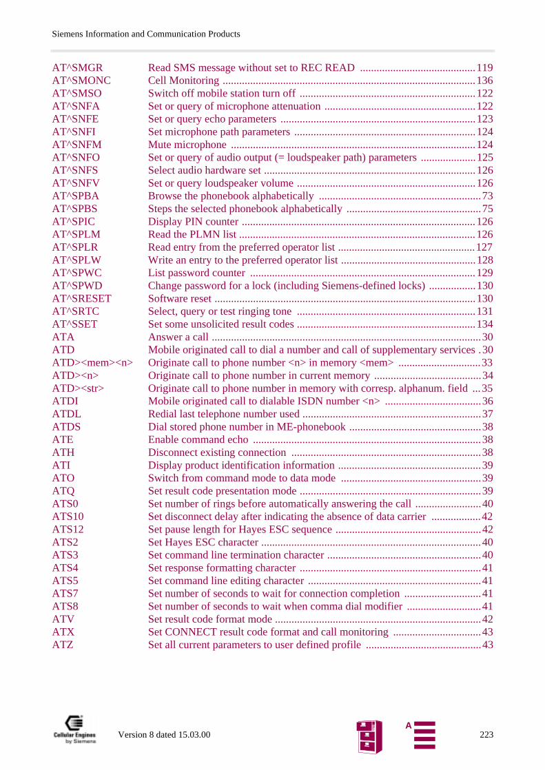
Siemens Information and Communication Products
AT^SMGR Read SMS message without set to REC READ ..........................................119AT^SMONC Cell Monitoring ............................................................................................136AT^SMSO Switch off mobile station turn off ................................................................122AT^SNFA Set or query of microphone attenuation .......................................................122AT^SNFE Set or query echo parameters .......................................................................123AT^SNFI Set microphone path parameters ..................................................................124AT^SNFM Mute microphone .........................................................................................124AT^SNFO Set or query of audio output (= loudspeaker path) parameters ....................125AT^SNFS Select audio hardware set .............................................................................126AT^SNFV Set or query loudspeaker volume .................................................................126AT^SPBA Browse the phonebook alphabetically ...........................................................73AT^SPBS Steps the selected phonebook alphabetically .................................................75AT^SPIC Display PIN counter .....................................................................................126AT^SPLM Read the PLMN list ......................................................................................126AT^SPLR Read entry from the preferred operator list ..................................................127AT^SPLW Write an entry to the preferred operator list .................................................128AT^SPWC List password counter ..................................................................................129AT^SPWD Change password for a lock (including Siemens-defined locks) .................130AT^SRESET Software reset ...............................................................................................130AT^SRTC Select, query or test ringing tone .................................................................131AT^SSET Set some unsolicited result codes .................................................................134ATA Answer a call ..................................................................................................30ATD Mobile originated call to dial a number and call of supplementary services .30ATD><mem><n> Originate call to phone number <n> in memory <mem> ..............................33ATD><n> Originate call to phone number in current memory .......................................34ATD><str> Originate call to phone number in memory with corresp. alphanum. field ...35ATDI Mobile originated call to dialable ISDN number <n> ...................................36ATDL Redial last telephone number used .................................................................37ATDS Dial stored phone number in ME-phonebook ................................................38ATE Enable command echo ...................................................................................38ATH Disconnect existing connection .....................................................................38ATI Display product identification information ....................................................39ATO Switch from command mode to data mode ...................................................39ATQ Set result code presentation mode ..................................................................39ATS0 Set number of rings before automatically answering the call ........................40ATS10 Set disconnect delay after indicating the absence of data carrier ..................42ATS12 Set pause length for Hayes ESC sequence .....................................................42ATS2 Set Hayes ESC character ................................................................................40ATS3 Set command line termination character ........................................................40ATS4 Set response formatting character ..................................................................41ATS5 Set command line editing character ...............................................................41ATS7 Set number of seconds to wait for connection completion ............................41ATS8 Set number of seconds to wait when comma dial modifier ...........................41ATV Set result code format mode ...........................................................................42ATX Set CONNECT result code format and call monitoring ................................43ATZ Set all current parameters to user defined profile ..........................................43
Version 8 dated 15.03.00 223A

Siemens Information and Communication Products
Version 8 dated 15.03.00 224A
Siemens Information and Communication Products
AbbreviationsAC ........................ Alternate CurrentACM..................... Accumulated Call MeterADC ..................... Analog Digital ConverterAGC ..................... Automatic Gain ControlAoC ...................... Advice of ChargeBAIC ...................... Barring of All Incoming CallsBAOC................... Barring of All Outgoing CallsBOIC ...................... Barring of Outgoing International CallsCBM..................... Cell Broadcast MessageCBS ...................... Cell Broadcasting ServiceCD ........................ Call DeflectionCFB......................... Call Forwarding on Mobile Subscriber BusyCFNRy ................... Call Forwarding on No ReplyCFNRc ................... Call Forwarding on Mobile Subscriber Not ReachableCFU ...................... Call Forwarding UnconditionalCH ........................ Call HoldCI.......................... Cell IDCLI ....................... Calling Line IdentificationCLIP ..................... Calling Line Identification PresentationCLIR..................... Calling Line Identification RestrictionCLLP .................... Closed Local Loop PhoneCME ERROR....... Mobile Equipment ErrorCMS ERROR ....... Mobile Equipment or Network ErrorCODEC ................ Coder-DecoderCOL...................... Connected LineCOLP.................... Connected Line Identification PresentationCTS....................... Clear To SendCUG ..................... Closed User GroupCW ....................... Call WaitingDAC ..................... Digital Analog ConverterDAI ......................... Digital Audio InterfacedB ......................... decibeldb SPL .................. dB Sound Pressure Level (0dB SPL ≡ 20µPa)DAI....................... Digital Audio InterfaceDCD ..................... Data Carrier DetectDCE...................... Data Circuit terminating EquipmentDRX ..................... Discontinuous reception (mechanism)DTC...................... Data Circuit Terminating EquipmentDTE ...................... Data Terminal EquipmentDTMF................... Dual-Tone MultifrequencyDTR...................... Data Terminal ReadyDSR ...................... Data Set ReadyDTR...................... Data Terminal ReadyEFR....................... Enhanced Full RateEMC ..................... Electromagnetic ConformityESD ...................... Electrostatic DischargeETS....................... European Telecommunications StandardFDN...................... Fixed Dialling NumberFR......................... Full RateGND ..................... GroundGPIO..................... General Purpose Interface
Version 8 dated 15.03.00 225A
Siemens Information and Communication Products
GSM ..................... Global System for Mobile communicationIMEI ..................... International Mobile Equipment IdentityIMSI ..................... International Mobile Subscriber IdentificationLAI ......................... Location Area IdentifierME........................ Mobile EquipmentMMI ..................... Man Machine InterfaceMO ....................... Mobile OriginatedMP ........................ Mobile PhoneMSVC................... Microsoft Visual CMT........................ Mobile TerminatedMTBF................... Mean Time Between FailureMTPy.................... Multiparty ServicePCB ...................... Printed Circuit BoardPDU...................... Protocol Data UnitPLMN................... Public Land Mobile NetworkPP ......................... Point-to-PointPSTN .................... Public Switched Telephone NetworkPtP ........................ Print-to-PrintRF ......................... Radio FrequencyRI.......................... Ring IndicatorRLP....................... Radio Link ProtocolRSSI ..................... Received Signal StrengthRTS....................... Request To SendRXD ..................... Receive DataSIM....................... Subscriber Interface ModuleSMS MO .............. SMS Mobile OriginatedSMS MT............... SMS Mobile TerminatedSMS...................... Short Message ServiceTA......................... Terminal AdapterTBR ...................... Technical Basis for RegulationTCH...................... Traffic ChannelTE ......................... Terminal EquipmentTHD...................... Total Harmonic DistortionTÜV...................... Technischer Überwachungsverein (German Technical Inspectorate)TXD...................... Transmit DataUSSD...................... Unstructured SS DataVSC........................ Voiceband Serial ConnectorVSWR .................. Voltage Standing Wave Ratio
Version 8 dated 15.03.00 226A
Siemens Information and Communication Products
d
o
a-
-
s
nce
e
Index
Numerics4-pole Western plug ..................... 203, 20480-pin connector .................................. 196
AAbbreviated dialling ............................. 147
keys – check................................... 150keys – programming....................... 150
Accumulatedcall meter........................................ 56call meter (ACM)........................... 112call meter maximum........................ 57
ACM ............................................ 56, 112Activity status....................................... 71Additional capabilities........................... 48Advice of Charge........................... 56, 111Advice of Charge information........... 55, 58Alphanumeric field.......................... 35, 71Answer a call........................................ 30Antenna
cable.............................................. 203connector............................... 157, 202gain................................................ 26GSM ............................................. 154help............................................... 174interface connector.......................... 26maximum power.............................. 26SMR nano connector........................ 26
Application examples........................... 198Asynchronous.................................. 82, 83Asynchronous modem........................... 59AT command........................................ 54
interface................... 13, 15, 20, 27, 154standard.......................................... 27standard Hayes................................ 29syntax............................................. 27to GSM........................................... 93
AT&F ................................................. 163AT&V ................................................ 164AT&W ................................................ 163AT+CLCK .......................................... 163AT+CPBS................................... 164, 165AT+CPBW ................................. 165, 169AT+CPIN ..................... 162, 169, 170, 171AT+CPWD ................................. 163, 171AT+CUSD Unstructured supplementary ser-
vice data.................................... 88
AT^SFPCS Far party call status............ 115AT^SMGL List SMS messages from preferred
storage without changing status to rea118
AT^SMGR Read SMS message without set tREC READ............................. 119
AT^SMONC Cell Monitoring............... 136AT^SPIC.............................. 162, 170, 171AT^SPLR Read entry from the preferred oper
tor list...................................... 127AT^SPLW Write an entry to the preferred ope
rator list................................... 128AT^SPWC List all current values of SIM counter
129AT^SRESET Software reset................. 130AT^SSET Set some unsolicited result codes...
134ATS12 Set pause length for Hayes ESC seque
42ATS2 Set Hayes ESC character.............. 40ATZ ................................................... 163Audio................................................. 196
hardware................................ 111, 126interface.................................... 22, 25mode............................... 123, 124, 126output.................................... 111, 125
Automaticanswering........................................ 40dialling...................................... 29, 46
Automatically answering........................ 40
BBAIC ............................... 66, 79, 116, 130BAOC.............................. 66, 79, 116, 130Bar all incoming calls (BAIC).. 66, 79, 116,
130Bar all outgoing calls (BAOC).. 66, 79, 116,
130Bar incoming calls when roaming outside the
home country (BIC-Roam).... 66, 79, 116, 130
Bar outgoing international calls (BOIC).. 66, 79, 116, 130
Bar outgoing international calls except to homcountry (BOIC-exHC)... 66, 79, 116, 130
Barring............................................... 145Battery...................................... 24, 56, 58
charge............................................. 58Baud rate.............................................. 53
Version 8 dated 15.03.00 227
Siemens Information and Communication Products
Bauds per second .................................. 52Bearer Service ...................................... 59Bearer service ....................................... 62BIC-Roam......................... 66, 79, 116, 130BOIC ................................ 14, 66, 116, 130BOIC-exHC ...................... 66, 79, 116, 130BuildCommDCB ................................. 178Busy
signal.............................................. 43tone ............................................... 146
Buzzer .......................................... 25, 142
CCall barring ................................. 144, 150Call forwarding.................. 55, 60, 144, 151Call hold ......................................... 55, 64Call in progress..................................... 17Call monitoring................................ 28, 43Call waiting.......................................... 62Calling line identification presentation .... 67Calling line identification restriction 68, 144Card ID............................................... 136Card identification ....................... 113, 137CCFC .................................................. 55CCIN switch......................................... 24CCM ................................................... 58CE conformity ............................... 15, 206Cell broadcast messages ....................... 106Cell ID ................................................ 133Cellular result code .......................... 55, 82Change password .................... 79, 130, 145Channel bit error rate............................. 87Channel number........................... 133, 135CHUP .................................................. 55CLCK .................................................. 55Clear down.......................................... 146Clear to send.................................. 51, 204ClearCommBreak ................................ 179CLIP............................................... 55, 67CLIR ..................................... 68, 144, 146Clock ................................................... 22Closed user group ................................. 61CMEE.................................................. 55CN_EVENT ........................................ 181CN_TRANSMIT ................................. 181Code presentation mode......................... 39Codec – A/D device.............................. 22COMM.DRV....................................... 181comma dial modifier............................. 41Command executed............................... 27
Command mode.............................. 29, 39Communications device....................... 179Connect indicator................................ 143Connect line identification presentation... 14CONNECT result.................................. 43Connected............................................. 69Connected line identification presentation69Connection completion.......................... 41Connection setup................................... 27Control character framing....................... 50Corporate personalization..................... 116CPBR................................................... 55CPBS................................................... 55CPBW.................................................. 55CPIN.................................................... 55CPWD.................................................. 55CREG.................................................. 55CTS................................................... 204Current call meter.................................. 58Current calls......................................... 65Current consumption.............................. 17Current memory.................................... 34Current power level............................. 133Current pulse........................................ 17
DData call............................................... 81Data carrier detect............................... 204Data carrier detect (DCD)................. 28, 43Data compression............................ 47, 48Data mode................................. 29, 30, 39Data rate............................................... 53Data set ready (DSR)...................... 44, 204Data terminal ready (DTR).............. 44, 204Data transfer....................................... 169DC_IN ................................................. 17DCB................................................... 178DCB FAR........................................... 178DCD ....................................... 38, 43, 204Dedicated mode................................... 133Delta-type approval............................. 197Design drawing (M20)......................... 213Destination address......................... 96, 101Development Box................................ 207Device definition................................. 178Dial a number....................................... 30Dial key.............................................. 142Dial stored phone number....................... 38DIAL TONE ......................................... 27Dial tone............................................... 43
Version 8 dated 15.03.00 228
Siemens Information and Communication Products
Dialling memory .............................. 46, 66Digital audio interface – DAI................. 22Dimensions......................................... 203Dimensions M20.................................. 212Discharge time..................................... 100Disconnect...................................... 27, 38Display....... 19, 39, 113, 126, 149, 157, 196
card ID.......................................... 136current configuration................... 28, 45information.................................... 143text................................................ 144
DOT display.................................. 19, 212Download enable.................................. 16DSR ............................................. 44, 204DTMF........................................... 56, 151DTMF generation................................. 92DTR ............................................. 44, 204
EEcho
mode.............................................. 38parameter........................................ 38parameters............................. 111, 123suppression....................... 22, 123, 200
EMC consideration.............................. 197Emergency call....................... 33, 139, 153EnableCommNotification..................... 180EscapeCommFunction.......................... 181Even.................................................... 50Execution command.............................. 54Explicit call transfer.............................. 64Extended error report........................ 55, 63
FFacility lock ................ 55, 66, 79, 111, 116Fax................................................. 55, 89
report manufactured identification..... 89report model identification................ 89report revision identification............. 90
Field strength indicator................. 143, 153Find phonebook entries..................... 55, 71Fixdialling
memory..................................... 28, 46phonebook................................. 33, 74
Fixed local rate................................ 29, 53FlushComm......................................... 182Format mode................................... 28, 42Formatting character........................ 28, 41Forwarding......................... 14, 55, 60, 151Frequency....................................... 12, 26
FTA – Full-type approval..................... 196Full-type approval............................... 196Function mode................................ 43, 44Fuses.................................................. 196
GGain...................................... 90, 123, 125Gain selection............................ 56, 90, 91GetCommError................................... 183GetCommEventMask........................... 184GetCommState.................................... 184Global object identification.............. 29, 50GND – ground............................... 24, 204Ground (GND)......................... 17, 24, 204GSM
07.07....................................... 27, 21207.07 (list of commands).................. 5507.07 and 07.05............................... 5411.11.............................................. 24standards....................................... 212
HHandset................. 156, 196, 197, 202, 204Handset (microphone and loudspeaker). 142Handset answer functions..................... 146Handset approval................................. 197Handset connection.............................. 199Handsfree – M20................................... 22Handsfree application.......................... 200Hang up call.................................... 55, 64Header.................................................. 42Home network................................. 70, 84Hook off............................................... 30Hookswitch........................................... 25
IIdle mode.............................. 17, 111, 133IGNITION ...................... 18, 122, 191, 205Ignition.................................. 16, 192, 203Ignition line........................................ 200IMEI .................................................... 64IMSI .................................................... 65Incoming barring services.. 66, 79, 116, 130Incoming call indication......................... 82Indicating of absence of data carrier........ 42Indicating the absence of data carrier....... 28International mobile subscriber identity.. 55,
65Invalid command................................... 27
Version 8 dated 15.03.00 229
Siemens Information and Communication Products
ISDN number .................................. 36, 46
KKeypad .................................... 11, 20, 158
address matrix ................................ 142column ........................................... 20meaning......................................... 142redial ............................................. 143row................................................. 20
Keypad column..................................... 20Keypad row .......................................... 20
LLanguage volume setting ...................... 153Languages ........................................... 142Last-dialling phonebook ........................ 33LED.................................................... 205Line editing character ............................ 41Line termination character ................ 28, 40Line-in/out ........................... 192, 202, 203Link not established .............................. 27Local call barring ......................... 144, 150Local data flow control ..................... 29, 51Local rate reporting mode ................. 29, 52Location area ID .......................... 133, 135Lock phone to SIM card ........................ 66Lock SIM card................................. 66, 79Logic level ........................................... 17Loudspeaker volume .................... 111, 126LPCSTR ............................................. 178
MM20
design drawing ............................... 213EMC-relevant information............... 196service information ......................... 201Terminal ........................................ 202
M20 diagnostics................................... 174Manufacturer
defaults...................................... 28, 44ID .................................................. 89identification ................... 29, 49, 55, 63
Manufacturer-specific AT commands ..... 27ME
phonebook ...................................... 38ME-phonebook ..................................... 28Message indicator ................................ 143Messages returned................................. 27Microphone ........ 25, 56, 123, 124, 196, 204
attenuation.............................. 111, 122energy........................................... 123gain selection................................... 91impedance ....................................... 25mute ...................................... 111, 124sensitivity........................................ 25signal to noise ratio .......................... 25volume............................................ 25
Minimal receiving level ....................... 133MMI
basic codes (ETS 300-511).............. 145board ............................................ 212codes ............................................ 144features and user-defined settings .... 143functions ....................................... 146
Mobile busy .......................................... 60Mobile equipment error.......................... 68Mobile originated call ................. 28, 30, 36Model identification............... 29, 49, 55, 63Mounting............................................ 216MTBF M20 ........................................ 212Multi-numbering .......................... 156, 159Multiparty............................................. 64Mute .................................................. 111
NNeighbour cells ................................... 135Network
call barring .................................... 150facility ..................................... 66, 116personalization............................... 116registration ................................ 55, 84selection................................. 144, 153service ............................... 60, 66, 116subset personalization..................... 116
NO DIAL TONE................................... 27No reply ........................................ 60, 151Non-transparent............. 59, 81, 82, 83, 212Non-voice call. 31, 33, 34, 35, 36, 37, 38, 46Not reachable ........................................ 60Number of rings .............................. 28, 40
OOdd...................................................... 50Off-hook............................................. 146OpenComm ........................................ 185Operator selection............................ 55, 70Operators..................................... 156, 159Originating address.............................. 101Outgoing barring service .... 66, 79, 116, 130
Version 8 dated 15.03.00 230
Siemens Information and Communication Products
Outgoing call ........................................ 31Outgoing seizure .................................. 147
PParity ................................................... 50Password......... 55, 66, 77, 79, 116, 130, 145password ............................................. 130PCM .................................................... 22PDU mode ........................ 94, 97, 100, 119Peripheral devices ................................ 154PHONE CALL .................................... 169Phonebook ................ 33, 71, 72, 74, 76, 95Phonebook handling ............................. 164PIN.................................... 56, 57, 77, 153
check............................................. 162counter .......................................... 126enter .............................................. 162
PIN2 .......................................... 56, 57, 77PLMN ID code ............................ 133, 135PLMN list ........................................... 126Plug FME............................................ 154Plug SMR nano.................................... 157Plug, Western ...................................... 203Port rate ............................................... 52Power on/off......................................... 18Power supply .......................... 17, 192, 203Power supply indicator ............ 24, 143, 153POWER_ON ................................. 18, 191Power-on indicator ................................ 18Prefix................................................... 27Product identification information .......... 39Product serial number identification........ 64Protection class ............................ 203, 216PUK .................................................... 77Push/pull cycles .................................... 26Push-pull cycles SMD connector ............ 17
RRACH channel .................................... 133Radio link protocol................................ 81Read command ..................................... 54Read current phonebook entries.............. 72ReadComm ................................. 178, 187Ready for receiving ............................... 51Receive data ........................................ 204Received signal strength indication ......... 87Receiving level ............................ 133, 135Receiving quality ................................. 133Recipient address .................................. 96Redial ............................. 37, 142, 147, 150
Remote station busy............................... 27Repeat previous command line ............... 29Report manufactured identification ......... 89Report model identification .................... 89Report revision identification.................. 90Request to send ................................... 204Reset indicator ...................................... 18RI ...................................................... 204Ring detection ....................................... 27Ring indicator ..................................... 204Ringer
tone .............................................. 144volume................................... 144, 153
Ringing tone ....................................... 131RLP – Radio link protocol...................... 81Roaming indicator............................... 143RS323.................................................. 20RSSI.................................... 135, 143, 153
field strength................................. 153value............................................. 133
RTS................................................... 204RXD .................................................. 204
SSACM................................................ 111SCID.................................................. 111SCKS................................................. 111SCNI.................................................. 111Select message service......................... 109Select phonebook memory storage.......... 74SEND................................................. 147Sending successful............................... 100Sensitivity...................................... 25, 212Serial interface.................................... 204Serial interface configuration................ 177Serial number identification.................... 64Service
provider personalization.............. 9, 116providers................................ 156, 159reporting control.............................. 83
Service centre time-stamp.................... 100Set command........................................ 54SetCommBreak................................... 187SetCommEventMask........................... 188SetCommState.................................... 189Short keys........................................... 142Short message..................................... 142Signal................................................... 87Signal quality........................................ 87Signal to noise ratio............................... 25
Version 8 dated 15.03.00 231
Siemens Information and Communication Products
SIMcard reader ..................................... 196connected presentation .................... 113connected status ............................. 113lock ............................................... 153message storage.............................. 105phonebook ................................. 33, 74PIN2..................................... 56, 57, 77
SIM card .................................... 8, 66, 116clock .............................................. 24identification number ...................... 113inserted switch ................................ 24interface.......................................... 24PIN ............................................... 130power supply................................... 24reader .................................... 154, 202reader approval............................... 197
SLCK ................................................. 111SMD connector, 80-pole ....................... 157SMGO ................................................ 111SMR connector – push/pull cycles.......... 26SMR nano................................... 154, 157SMS
cell broadcast................................. 104COMMAND ..... 94, 95, 97, 98, 119, 120delete message................................ 93DELIVER.............. 94, 97, 98, 119, 120destination address........ 95, 97, 100, 119discharge time..................... 95, 98, 120message format............................... 94message from preferred message storage....
93message identifier................ 96, 98, 120message overflow........................... 152messages from preferred store........... 94new message indication................... 103originating address.................... 98, 120overflow........................................ 118PDU mode.......................... 94, 98, 120preferred message storage................ 105read message................................... 97reading a message........................... 151received read messages.................... 94received unread messages................. 94recipient address.................. 96, 98, 120restore settings............................... 105save settings................................... 106scrolling through message............... 151select cell broadcast messages.......... 106select message service..................... 109
send message................................. 100send message from storage.............. 102service centre address..................... 106service centre time-stamp..... 96, 99, 121service indicator............................. 152set text mode parameter.................. 109show text mode parameter............... 108STATUS-REPORT.. 94, 95, 97, 98, 119,
120stored sent messages......................... 94stored unsent messages..................... 94SUBMIT ................ 94, 95, 98, 100, 120switch off mobile station................. 122text mode.................... 94, 98, 100, 120user data header indication......... 98, 120with M20 to SIM (in text mode)...... 170write message to memory................ 101
SMSO................................................ 111SNFM................................................ 111SNFS................................................. 111SNFV................................................. 111Software
status........................................ 49, 63update........................................... 191
Software download.............................. 191Software library................................... 177Software release.................................... 39Software status................................ 49, 63Speaker................................... 25, 90, 204
gain selection................................... 90volume.......................................... 144
Speaker volume................................... 144SPIC.................................................. 111SPLM................................................. 111SPWD................................................ 111SRTC................................................. 111Standard AT Hayes commands............... 28Stand-by state (power)........................... 17State of call........................................... 65Status LED......................................... 205Store current parameter.................... 43, 45Store telephone number.......................... 46stored................................................... 37Stored number............ 33, 34, 35, 37, 38, 46Subaddress............................................ 60SUB-D............................................... 204SW
downloading.................................. 191Switch off........................................... 122Switch on............................................. 18
Version 8 dated 15.03.00 232
Siemens Information and Communication Products
Synchronous.................................... 82, 83
TTechnical data, M20 ............................. 212Temperature range ....................... 203, 212Termination character............................ 27Test command ...................................... 54Text mode 94, 95, 97, 98, 100, 119, 120, 170Text mode parameter............................ 108Time slot............................................. 133Timeout ............................................... 27Timing advice in bits............................ 133Timing characteristics of DAI ................ 23Timing of display interface .................... 19Tone generation .................................... 92Trailer.................................................. 42Transmit data................................. 22, 204TransmitCommChar............................. 190Transparent .............................. 59, 83, 212Turn off ........................................ 18, 122Turn on ................................................ 18TXD ................................................... 204
UUnconditional ....................................... 60UngetCommCha .................................. 190Unused pins..................................... 16, 17Update ................................................ 191User defined profile............................... 43Using the AT^SPBA and AT^SPBS Command
168
VV.21 .................................................... 59V.22 .................................................... 59V.22bis ................................................ 59V.23 .................................................... 59V.24 .................................................... 20V.25ter............................ 27, 29, 30, 31, 69V.26ter................................................. 59V.28 ................................................... 203V.32 .................................................... 59V.42bis .................................... 47, 48, 212Vibrations ........................................... 203Voice call ............................................. 31Voice parameter............................... 56, 91Voiceband serial ports ........................... 22Voltage supply..................................... 212Volume ......................................... 25, 153
Volume setting .................................... 153
WWeight ............................................... 203Weight M20........................................ 212WM_COMMNOTIFY ......................... 180Write phonebook entry........................... 76WriteComm ................................. 178, 191
XXON/XOFF .......................................... 51
Version 8 dated 15.03.00 233