siemens s5 3964r - opcturkey.comopcturkey.com/uploads/manuals/siemens-s5-3964r-manual.pdf ·...
TRANSCRIPT
Siemens S5 3964RDriver
© 2016 PTC Inc. All Rights Reserved.
Siemens S5 3964R Driver
TableofContentsSiemens S5 3964R Driver 1
Table of Contents 2
Siemens S5 3964R Driver 3
Overview 3
Setup 4
ModemSetup 4
Channel Properties 4
Channel Properties - General 5
Channel Properties - Serial Communications 5
Channel Properties - Write Optimizations 8
Channel Properties - Advanced 9
Driver Device Properties 10
Device Properties - General 10
Device Properties - Scan Mode 12
Device Properties - Timing 12
Device Properties - Auto-Demotion 13
Device Properties - Protocol Options 14
Device Properties - String Options 15
Device Properties - Redundancy 15
Data Types Description 16
Address Descriptions 17
Event Log Messages 22
Read request returned error code. | Tag address = '<address>', Error code = <hex> (<decimal>). 22
Write request returned error code. | Tag address = '<address>', Error code = <hex> (<decimal>). 22
Bad block. The block has been deactivated. | Starting address = '<address>', Block size = <count>(elements). 22
Error Mask Definitions 23
Index 24
www.kepware.com
2
Siemens S5 3964R Driver
Siemens S5 3964R DriverHelp version 1.025
CONTENTS
OverviewWhat is the Siemens S5 3964R Driver?
Device SetupHow do I configure a device for use with this driver?
Data Types DescriptionWhat data types does this driver support?
Address DescriptionsHow do I address a data location on a Siemens S5 (3964R) device?
Event Log MessagesWhat are the messages for the Siemens S5 3964R Driver?
OverviewThe Siemens S5 3964R Driver provides a reliable way to connect Siemens S5 (3964R) devices to OPC Clientapplications, including HMI, SCADA, Historian, MES, ERP, and countless custom applications. It is intendedfor use with Siemens S5 PLCs communicating via a communications processor card (such as the CP 544)configured to use the 3964R. It can also be used with 3964 protocols and the RK 512 computer link. MultipleCPU systems are supported.
Note: This driver is not designed to respond to unsolicited data from the PLC.
www.kepware.com
3
Siemens S5 3964R Driver
SetupSupported DevicesAny device that supports 3964 or 3964R protocol and uses the RK 512 computer link program.
Communication Protocols3964R3964Note: The 3964 variant is identical to 3964R, except it does not use a Byte Check Character (BCC).
Supported Communication ParametersValues depend on the communications processor card used and its configuration. The following values aretypical settings:
Baud: 300 to 19200Parity: EvenData Bits: 8Stop Bits: 1
Device ConfigurationThe device must be configured to operate in slave mode with low priority partner.
Unsolicited MessagesThis driver accepts and acknowledges unsolicited messages from the PLC, but does not use them. Foroptimum driver performance, unsolicited messages are discouraged.
See Also:Channel PropertiesDevice Properties
Modem SetupThis driver supports modem functionality. For more information, please refer to the topic "Modem Support"in the server help documentation.
Channel PropertiesThis server supports the use of simultaneous multiple communications drivers. Each protocol or driver usedin a server project is called a channel. A server project may consist of many channels with the samecommunications driver or with unique communications drivers. A channel acts as the basic building block ofan OPC link.
The properties associated with a channel are broken in to logical groupings. While some groups are specificto a given driver or protocol, the following are the common groups:
GeneralEthernet or Serial CommunicationsWrite OptimizationAdvanced
www.kepware.com
4
Siemens S5 3964R Driver
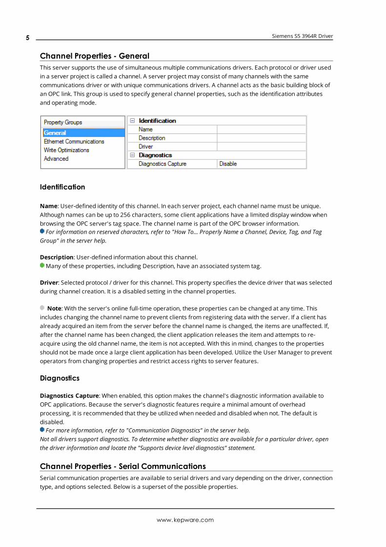
Channel Properties - GeneralThis server supports the use of simultaneous multiple communications drivers. Each protocol or driver usedin a server project is called a channel. A server project may consist of many channels with the samecommunications driver or with unique communications drivers. A channel acts as the basic building block ofan OPC link. This group is used to specify general channel properties, such as the identification attributesand operating mode.
Identification
Name: User-defined identity of this channel. In each server project, each channel name must be unique.Although names can be up to 256 characters, some client applications have a limited display window whenbrowsing the OPC server's tag space. The channel name is part of the OPC browser information.For information on reserved characters, refer to "How To... Properly Name a Channel, Device, Tag, and Tag
Group" in the server help.
Description: User-defined information about this channel. Many of these properties, including Description, have an associated system tag.
Driver: Selected protocol / driver for this channel. This property specifies the device driver that was selectedduring channel creation. It is a disabled setting in the channel properties.
Note: With the server's online full-time operation, these properties can be changed at any time. Thisincludes changing the channel name to prevent clients from registering data with the server. If a client hasalready acquired an item from the server before the channel name is changed, the items are unaffected. If,after the channel name has been changed, the client application releases the item and attempts to re-acquire using the old channel name, the item is not accepted. With this in mind, changes to the propertiesshould not be made once a large client application has been developed. Utilize the User Manager to preventoperators from changing properties and restrict access rights to server features.
Diagnostics
Diagnostics Capture: When enabled, this optionmakes the channel's diagnostic information available toOPC applications. Because the server's diagnostic features require a minimal amount of overheadprocessing, it is recommended that they be utilized when needed and disabled when not. The default isdisabled.For more information, refer to "Communication Diagnostics" in the server help.
Not all drivers support diagnostics. To determine whether diagnostics are available for a particular driver, openthe driver information and locate the "Supports device level diagnostics" statement.
Channel Properties - Serial CommunicationsSerial communication properties are available to serial drivers and vary depending on the driver, connectiontype, and options selected. Below is a superset of the possible properties.
www.kepware.com
5
Siemens S5 3964R Driver
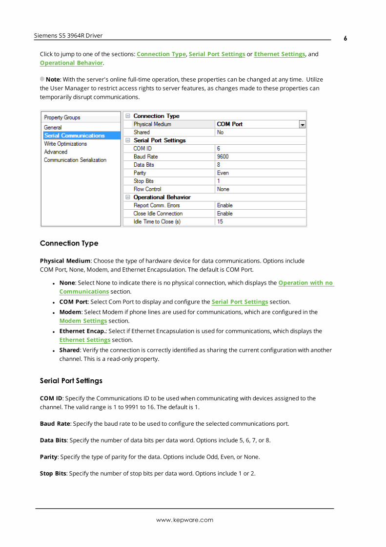
Click to jump to one of the sections: Connection Type, Serial Port Settings or Ethernet Settings, andOperational Behavior.
Note: With the server's online full-time operation, these properties can be changed at any time. Utilizethe User Manager to restrict access rights to server features, as changes made to these properties cantemporarily disrupt communications.
Connection Type
Physical Medium: Choose the type of hardware device for data communications. Options includeCOM Port, None, Modem, and Ethernet Encapsulation. The default is COM Port.
l None: Select None to indicate there is no physical connection, which displays the Operation with noCommunications section.
l COM Port: Select Com Port to display and configure the Serial Port Settings section.
l Modem: Select Modem if phone lines are used for communications, which are configured in theModem Settings section.
l Ethernet Encap.: Select if Ethernet Encapsulation is used for communications, which displays theEthernet Settings section.
l Shared: Verify the connection is correctly identified as sharing the current configuration with anotherchannel. This is a read-only property.
Serial Port Settings
COM ID: Specify the Communications ID to be used when communicating with devices assigned to thechannel. The valid range is 1 to 9991 to 16. The default is 1.
Baud Rate: Specify the baud rate to be used to configure the selected communications port.
Data Bits: Specify the number of data bits per data word. Options include 5, 6, 7, or 8.
Parity: Specify the type of parity for the data. Options include Odd, Even, or None.
Stop Bits: Specify the number of stop bits per data word. Options include 1 or 2.
www.kepware.com
6
Siemens S5 3964R Driver
Flow Control: Select how the RTS and DTR control lines are utilized. Flow control is required to communicatewith some serial devices. Options are:
l None: This option does not toggle or assert control lines.
l DTR: This option asserts the DTR line when the communications port is opened and remains on.
l RTS: This option specifies that the RTS line is high if bytes are available for transmission. After allbuffered bytes have been sent, the RTS line is low. This is normally used with RS232/RS485 converterhardware.
l RTS, DTR: This option is a combination of DTR and RTS.
l RTS Always: This option asserts the RTS line when the communication port is opened and remainson.
l RTS Manual: This option asserts the RTS line based on the timing properties entered for RTS LineControl. It is only available when the driver supports manual RTS line control (or when the propertiesare shared and at least one of the channels belongs to a driver that provides this support).RTS Manual adds an RTS Line Control property with options as follows:
l Raise: This property specifies the amount of time that the RTS line is raised prior to datatransmission. The valid range is 0 to 9999 milliseconds. The default is 10 milliseconds.
l Drop: This property specifies the amount of time that the RTS line remains high after datatransmission. The valid range is 0 to 9999 milliseconds. The default is 10 milliseconds.
l Poll Delay: This property specifies the amount of time that polling for communications isdelayed. The valid range is 0 to 9999. The default is 10 milliseconds.
Tip: When using two-wire RS-485, "echoes" may occur on the communication lines. Since thiscommunication does not support echo suppression, it is recommended that echoes be disabled or a RS-485converter be used.
Operational Behavior
l Report Comm. Errors: Enable or disable reporting of low-level communications errors. Whenenabled, low-level errors are posted to the Event Log as they occur. When disabled, these sameerrors are not posted even though normal request failures are. The default is Enable.
l Close Idle Connection: Choose to close the connection when there are no longer any tags beingreferenced by a client on the channel. The default is Enable.
l Idle Time to Close: Specify the amount of time that the server waits once all tags have beenremoved before closing the COM port. The default is 15 seconds.
Ethernet SettingsEthernet Encapsulation provides communication with serial devices connected to terminal servers on theEthernet network. A terminal server is essentially a virtual serial port that converts TCP/IP messages on theEthernet network to serial data. Once the message has been converted, users can connect standard devicesthat support serial communications to the terminal server. The terminal server's serial port must beproperly configured to match the requirements of the serial device to which it is attached. For moreinformation, refer to "How To... Use Ethernet Encapsulation" in the server help.
l Network Adapter: Indicate a network adapter to bind for Ethernet devices in this channel. Choose anetwork adapter to bind to or allow the OS to select the default.Specific drivers may display additional Ethernet Encapsulation properties. For more information, refer
to Channel Properties - Ethernet Encapsulation.
Modem Settings
www.kepware.com
7
Siemens S5 3964R Driver
l Modem: Specify the installed modem to be used for communications.
l Connect Timeout: Specify the amount of time to wait for connections to be established beforefailing a read or write. The default is 60 seconds.
l Modem Properties: Configure the modem hardware. When clicked, it opens vendor-specific modemproperties.
l Auto-Dial: Enables the automatic dialing of entries in the Phonebook. The default is Disable. Formore information, refer to "Modem Auto-Dial" in the server help.
l Report Comm. Errors: Enable or disable reporting of low-level communications errors. Whenenabled, low-level errors are posted to the Event Log as they occur. When disabled, these sameerrors are not posted even though normal request failures are. The default is Enable.
l Close Idle Connection: Choose to close the modem connection when there are no longer any tagsbeing referenced by a client on the channel. The default is Enable.
l Idle Time to Close: Specify the amount of time that the server waits once all tags have beenremoved before closing the modem connection. The default is 15 seconds.
Operation with no Communications
l Read Processing: Select the action to be taken when an explicit device read is requested. Optionsinclude Ignore and Fail. Ignore does nothing; Fail provides the client with an update that indicatesfailure. The default setting is Ignore.
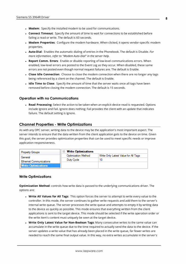
Channel Properties - Write OptimizationsAs with any OPC server, writing data to the device may be the application's most important aspect. Theserver intends to ensure that the data written from the client application gets to the device on time. Giventhis goal, the server provides optimization properties that can be used to meet specific needs or improveapplication responsiveness.
Write Optimizations
Optimization Method: controls how write data is passed to the underlying communications driver. Theoptions are:
l Write All Values for All Tags: This option forces the server to attempt to write every value to thecontroller. In this mode, the server continues to gather write requests and add them to the server'sinternal write queue. The server processes the write queue and attempts to empty it by writing datato the device as quickly as possible. This mode ensures that everything written from the clientapplications is sent to the target device. This mode should be selected if the write operation order orthe write item's content must uniquely be seen at the target device.
l Write Only Latest Value for Non-Boolean Tags: Many consecutive writes to the same value canaccumulate in the write queue due to the time required to actually send the data to the device. If theserver updates a write value that has already been placed in the write queue, far fewer writes areneeded to reach the same final output value. In this way, no extra writes accumulate in the server's
www.kepware.com
8
Siemens S5 3964R Driver
queue. When the user stops moving the slide switch, the value in the device is at the correct value atvirtually the same time. As the mode states, any value that is not a Boolean value is updated in theserver's internal write queue and sent to the device at the next possible opportunity. This can greatlyimprove the application performance.
Note: This option does not attempt to optimize writes to Boolean values. It allows users tooptimize the operation of HMI data without causing problems with Boolean operations, such as amomentary push button.
l Write Only Latest Value for All Tags: This option takes the theory behind the second optimizationmode and applies it to all tags. It is especially useful if the application only needs to send the latestvalue to the device. This mode optimizes all writes by updating the tags currently in the write queuebefore they are sent. This is the default mode.
Duty Cycle: is used to control the ratio of write to read operations. The ratio is always based on one read forevery one to ten writes. The duty cycle is set to ten by default, meaning that ten writes occur for each readoperation. Although the application is performing a large number of continuous writes, it must be ensuredthat read data is still given time to process. A setting of one results in one read operation for every writeoperation. If there are no write operations to perform, reads are processed continuously. This allowsoptimization for applications with continuous writes versus a more balanced back and forth data flow.
Note: It is recommended that the application be characterized for compatibility with the writeoptimization enhancements before being used in a production environment.
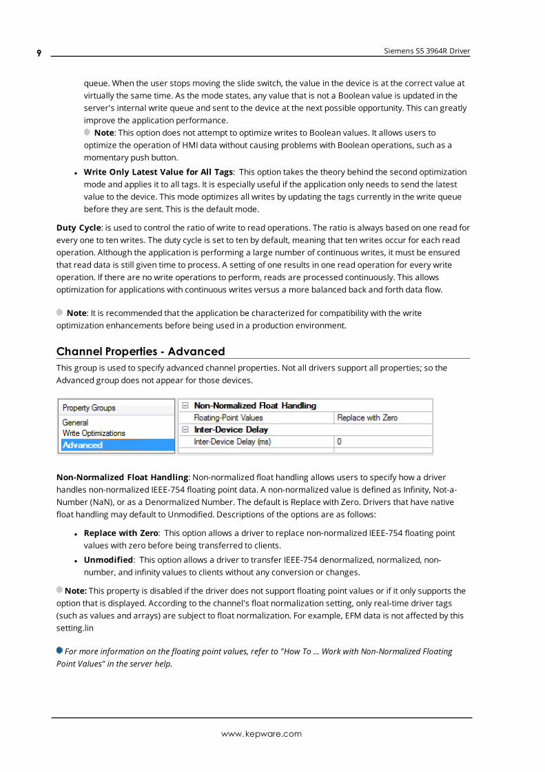
Channel Properties - AdvancedThis group is used to specify advanced channel properties. Not all drivers support all properties; so theAdvanced group does not appear for those devices.
Non-Normalized Float Handling: Non-normalized float handling allows users to specify how a driverhandles non-normalized IEEE-754 floating point data. A non-normalized value is defined as Infinity, Not-a-Number (NaN), or as a Denormalized Number. The default is Replace with Zero. Drivers that have nativefloat handling may default to Unmodified. Descriptions of the options are as follows:
l Replace with Zero: This option allows a driver to replace non-normalized IEEE-754 floating pointvalues with zero before being transferred to clients.
l Unmodified: This option allows a driver to transfer IEEE-754 denormalized, normalized, non-number, and infinity values to clients without any conversion or changes.
Note: This property is disabled if the driver does not support floating point values or if it only supports theoption that is displayed. According to the channel's float normalization setting, only real-time driver tags(such as values and arrays) are subject to float normalization. For example, EFM data is not affected by thissetting.lin
For more information on the floating point values, refer to "How To ... Work with Non-Normalized FloatingPoint Values" in the server help.
www.kepware.com
9
Siemens S5 3964R Driver
Inter-Device Delay: Specify the amount of time the communications channel waits to send new requests tothe next device after data is received from the current device on the same channel. Zero (0) disables thedelay.
Note: This property is not available for all drivers, models, and dependent settings.
Driver Device PropertiesDevice properties are organized into the following groups. Click on a link below for details about the settingsin that group.
GeneralScan ModeTimingAuto-DemotionProtocol OptionsString OptionsRedundancy
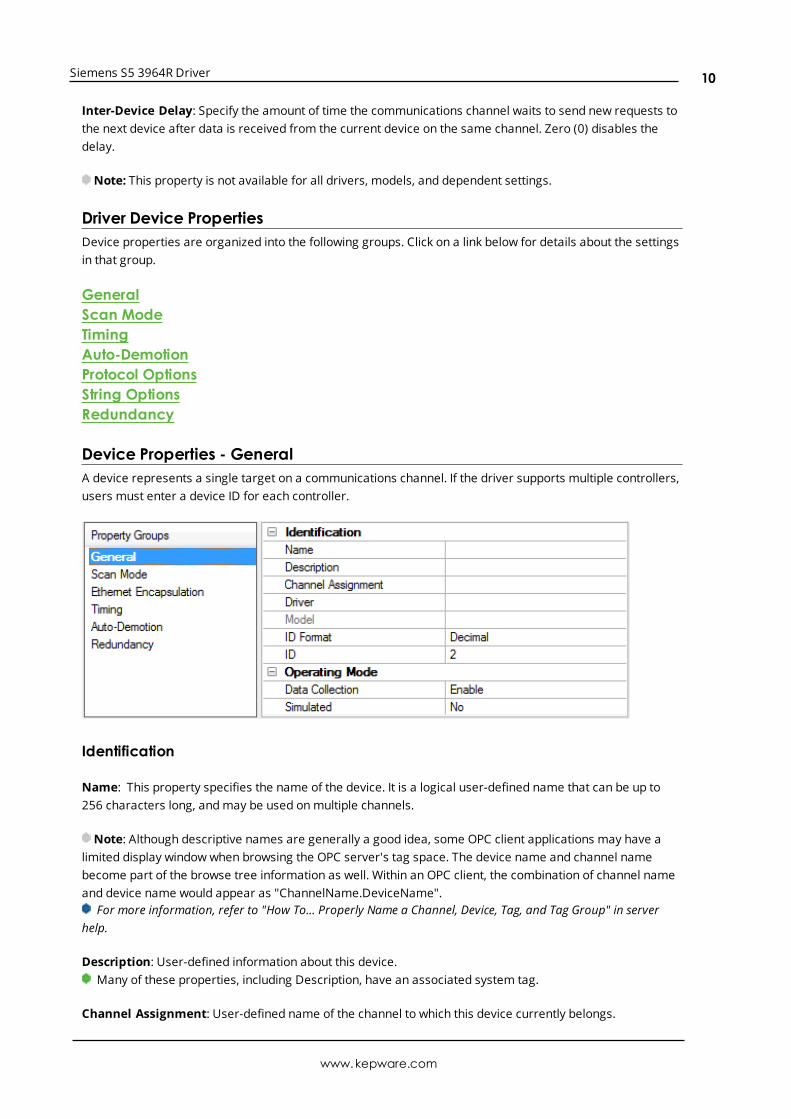
Device Properties - GeneralA device represents a single target on a communications channel. If the driver supports multiple controllers,users must enter a device ID for each controller.
Identification
Name: This property specifies the name of the device. It is a logical user-defined name that can be up to256 characters long, andmay be used onmultiple channels.
Note: Although descriptive names are generally a good idea, some OPC client applications may have alimited display window when browsing the OPC server's tag space. The device name and channel namebecome part of the browse tree information as well. Within an OPC client, the combination of channel nameand device name would appear as "ChannelName.DeviceName".
For more information, refer to "How To... Properly Name a Channel, Device, Tag, and Tag Group" in serverhelp.
Description: User-defined information about this device.Many of these properties, including Description, have an associated system tag.
Channel Assignment: User-defined name of the channel to which this device currently belongs.
www.kepware.com
10
Siemens S5 3964R Driver
Driver: Selected protocol driver for this device.
Model: This property specifies the specific type of device that is associated with this ID. The contents of thedrop-downmenu depends on the type of communications driver being used. Models that are not supportedby a driver are disabled. If the communications driver supports multiple device models, the model selectioncan only be changed when there are no client applications connected to the device.
Note: If the communication driver supports multiple models, users should try to match the modelselection to the physical device. If the device is not represented in the drop-downmenu, select a model thatconforms closest to the target device. Some drivers support a model selection called "Open," which allowsusers to communicate without knowing the specific details of the target device. For more information, referto the driver help documentation.
ID: This property specifies the device's driver-specific station or node. The type of ID entered depends onthe communications driver being used. For many communication drivers, the ID is a numeric value. Driversthat support a Numeric ID provide users with the option to enter a numeric value whose format can bechanged to suit the needs of the application or the characteristics of the selected communications driver.The ID format can be Decimal, Octal, and Hexadecimal.
Note: If the driver is Ethernet-based or supports an unconventional station or node name, the device'sTCP/IP address may be used as the device ID. TCP/IP addresses consist of four values that are separated byperiods, with each value in the range of 0 to 255. Some device IDs are string based. There may be additionalproperties to configure within the ID field, depending on the driver. For more information, refer to thedriver's help documentation.
Operating Mode
Data Collection: This property controls the device's active state. Although device communications areenabled by default, this property can be used to disable a physical device. Communications are notattempted when a device is disabled. From a client standpoint, the data is marked as invalid and writeoperations are not accepted. This property can be changed at any time through this property or the devicesystem tags.
Simulated: This option places the device into Simulation Mode. In this mode, the driver does not attempt tocommunicate with the physical device, but the server continues to return valid OPC data. Simulated stopsphysical communications with the device, but allows OPC data to be returned to the OPC client as valid data.While in Simulation Mode, the server treats all device data as reflective: whatever is written to the simulateddevice is read back and each OPC item is treated individually. The item's memory map is based on the groupUpdate Rate. The data is not saved if the server removes the item (such as when the server is reinitialized).The default is No.
Notes:
1. This System tag (_Simulated) is read only and cannot be written to for runtime protection. The Systemtag allows this property to be monitored from the client.
2. In Simulationmode, the item's memory map is based on client update rate(s) (Group Update Rate forOPC clients or Scan Rate for native and DDE interfaces). This means that two clients that referencethe same item with different update rates return different data.
Simulation Mode is for test and simulation purposes only. It should never be used in a productionenvironment.
www.kepware.com
11
Siemens S5 3964R Driver
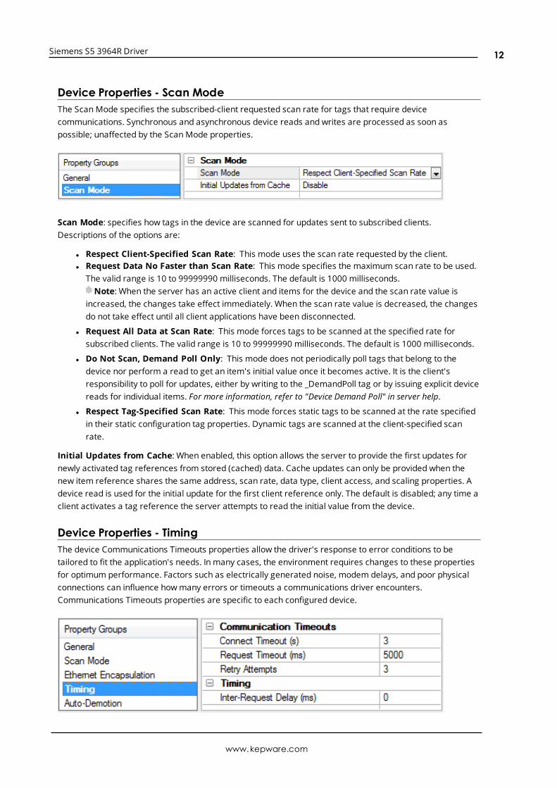
Device Properties - Scan ModeThe ScanMode specifies the subscribed-client requested scan rate for tags that require devicecommunications. Synchronous and asynchronous device reads and writes are processed as soon aspossible; unaffected by the ScanMode properties.
Scan Mode: specifies how tags in the device are scanned for updates sent to subscribed clients.Descriptions of the options are:
l Respect Client-Specified Scan Rate: This mode uses the scan rate requested by the client.l Request Data No Faster than Scan Rate: This mode specifies the maximum scan rate to be used.
The valid range is 10 to 99999990 milliseconds. The default is 1000 milliseconds.Note: When the server has an active client and items for the device and the scan rate value is
increased, the changes take effect immediately. When the scan rate value is decreased, the changesdo not take effect until all client applications have been disconnected.
l Request All Data at Scan Rate: This mode forces tags to be scanned at the specified rate forsubscribed clients. The valid range is 10 to 99999990 milliseconds. The default is 1000 milliseconds.
l Do Not Scan, Demand Poll Only: This mode does not periodically poll tags that belong to thedevice nor perform a read to get an item's initial value once it becomes active. It is the client'sresponsibility to poll for updates, either by writing to the _DemandPoll tag or by issuing explicit devicereads for individual items. For more information, refer to "Device Demand Poll" in server help.
l Respect Tag-Specified Scan Rate: This mode forces static tags to be scanned at the rate specifiedin their static configuration tag properties. Dynamic tags are scanned at the client-specified scanrate.
Initial Updates from Cache: When enabled, this option allows the server to provide the first updates fornewly activated tag references from stored (cached) data. Cache updates can only be provided when thenew item reference shares the same address, scan rate, data type, client access, and scaling properties. Adevice read is used for the initial update for the first client reference only. The default is disabled; any time aclient activates a tag reference the server attempts to read the initial value from the device.
Device Properties - TimingThe device Communications Timeouts properties allow the driver's response to error conditions to betailored to fit the application's needs. In many cases, the environment requires changes to these propertiesfor optimum performance. Factors such as electrically generated noise, modem delays, and poor physicalconnections can influence howmany errors or timeouts a communications driver encounters.Communications Timeouts properties are specific to each configured device.
www.kepware.com
12
Siemens S5 3964R Driver
Communications Timeouts
Connect Timeout: This property (which is used primarily by Ethernet based drivers) controls the amount oftime required to establish a socket connection to a remote device. The device's connection time often takeslonger than normal communications requests to that same device. The valid range is 1 to 30 seconds. Thedefault is typically 3 seconds, but can vary depending on the driver's specific nature. If this setting is notsupported by the driver, it is disabled.
Note: Due to the nature of UDP connections, the connection timeout setting is not applicable whencommunicating via UDP.
Request Timeout: This property specifies an interval used by all drivers to determine how long the driverwaits for a response from the target device to complete. The valid range is 50 to 9,999,999 milliseconds(167.6667 minutes). The default is usually 1000 milliseconds, but can vary depending on the driver. Thedefault timeout for most serial drivers is based on a baud rate of 9600 baud or better. When using a driverat lower baud rates, increase the timeout to compensate for the increased time required to acquire data.
Retry Attempts: This property specifies howmany times the driver retries a communications requestbefore considering the request to have failed and the device to be in error. The valid range is 1 to 10. Thedefault is typically 3, but can vary depending on the driver's specific nature. The number of retriesconfigured for an application depends largely on the communications environment.
Timing
Inter-Request Delay: This property specifies how long the driver waits before sending the next request tothe target device. It overrides the normal polling frequency of tags associated with the device, as well asone-time reads and writes. This delay can be useful when dealing with devices with slow turnaround timesand in cases where network load is a concern. Configuring a delay for a device affects communications withall other devices on the channel. It is recommended that users separate any device that requires an inter-request delay to a separate channel if possible. Other communications properties (such as communicationserialization) can extend this delay. The valid range is 0 to 300,000 milliseconds; however, some drivers maylimit the maximum value due to a function of their particular design. The default is 0, which indicates nodelay between requests with the target device.
Note: Not all drivers support Inter-Request Delay. This setting does not appear if it is not supported by thedriver.
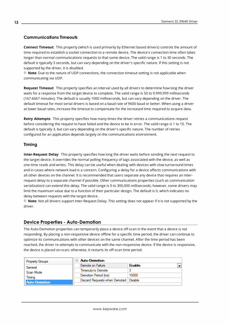
Device Properties - Auto-DemotionThe Auto-Demotion properties can temporarily place a device off-scan in the event that a device is notresponding. By placing a non-responsive device offline for a specific time period, the driver can continue tooptimize its communications with other devices on the same channel. After the time period has beenreached, the driver re-attempts to communicate with the non-responsive device. If the device is responsive,the device is placed on-scan; otherwise, it restarts its off-scan time period.
www.kepware.com
13
Siemens S5 3964R Driver
Demote on Failure: When enabled, the device is automatically taken off-scan until it is responding again.Tip: Determine when a device is off-scan by monitoring its demoted state using the _AutoDemoted
system tag.
Timeouts to Demote: Specify howmany successive cycles of request timeouts and retries occur before thedevice is placed off-scan. The valid range is 1 to 30 successive failures. The default is 3.
Demotion Period: Indicate how long the device should be placed off-scan when the timeouts value isreached. During this period, no read requests are sent to the device and all data associated with the readrequests are set to bad quality. When this period expires, the driver places the device on-scan and allows foranother attempt at communications. The valid range is 100 to 3600000 milliseconds. The default is 10000milliseconds.
Discard Requests when Demoted: Select whether or not write requests should be attempted during theoff-scan period. Disable to always send write requests regardless of the demotion period. Enable to discardwrites; the server automatically fails any write request received from a client and does not post a messageto the Event Log.
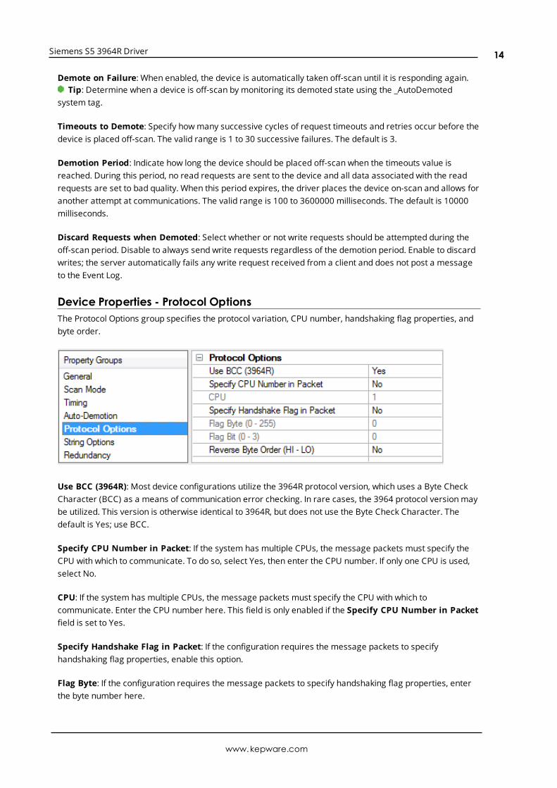
Device Properties - Protocol OptionsThe Protocol Options group specifies the protocol variation, CPU number, handshaking flag properties, andbyte order.
Use BCC (3964R): Most device configurations utilize the 3964R protocol version, which uses a Byte CheckCharacter (BCC) as a means of communication error checking. In rare cases, the 3964 protocol versionmaybe utilized. This version is otherwise identical to 3964R, but does not use the Byte Check Character. Thedefault is Yes; use BCC.
Specify CPU Number in Packet: If the system has multiple CPUs, the message packets must specify theCPU with which to communicate. To do so, select Yes, then enter the CPU number. If only one CPU is used,select No.
CPU: If the system has multiple CPUs, the message packets must specify the CPU with which tocommunicate. Enter the CPU number here. This field is only enabled if the Specify CPU Number in Packetfield is set to Yes.
Specify Handshake Flag in Packet: If the configuration requires the message packets to specifyhandshaking flag properties, enable this option.
Flag Byte: If the configuration requires the message packets to specify handshaking flag properties, enterthe byte number here.
www.kepware.com
14
Siemens S5 3964R Driver
Flag Bit: If the configuration requires the message packets to specify handshaking flag properties, enter thebit number here.
Reverse Byte Order (HI-LO): Siemens devices normally store multi-byte data values from least to mostsignificant byte (LO to HI). If the device is programmed to store data in the opposite order, select Yes toreverse the order to match the device.Note: This property does not affect string data.
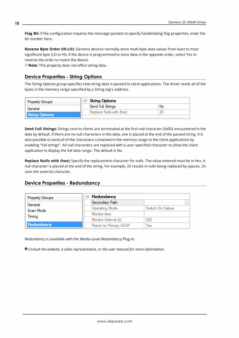
Device Properties - String OptionsThe String Options group specifies how string data is passed to client applications. The driver reads all of thebytes in the memory range specified by a String tag's address.
Send Full Strings: Strings sent to clients are terminated at the first null character (0x00) encountered in thedata by default. If there are no null characters in the data, one is placed at the end of the passed string. It isalso possible to send all of the characters contained in the memory range to the client applications byenabling "full strings". All null characters are replaced with a user-specified character to allow the clientapplication to display the full data range. The default is No.
Replace Nulls with (hex): Specify the replacement character for nulls. The value enteredmust be in hex. Anull character is placed at the end of the string. For example, 20 results in nulls being replaced by spaces, 2Auses the asterisk character.
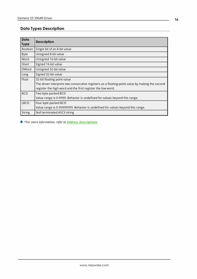
Device Properties - Redundancy
Redundancy is available with the Media-Level Redundancy Plug-in.
Consult the website, a sales representative, or the user manual for more information.
www.kepware.com
15
Siemens S5 3964R Driver
Data Types Description
DataType Description
Boolean Single bit of an 8-bit value
Byte Unsigned 8-bit value
Word Unsigned 16-bit value
Short Signed 16-bit value
DWord Unsigned 32-bit value
Long Signed 32-bit value
Float 32-bit floating point valueThe driver interprets two consecutive registers as a floating-point value by making the secondregister the high word and the first register the low word.
BCD Two byte packed BCDValue range is 0-9999. Behavior is undefined for values beyond this range.
LBCD Four byte packed BCDValue range is 0-99999999. Behavior is undefined for values beyond this range.
String Null terminated ASCII string
*For more information, refer to Address Descriptions.
www.kepware.com
16
Siemens S5 3964R Driver
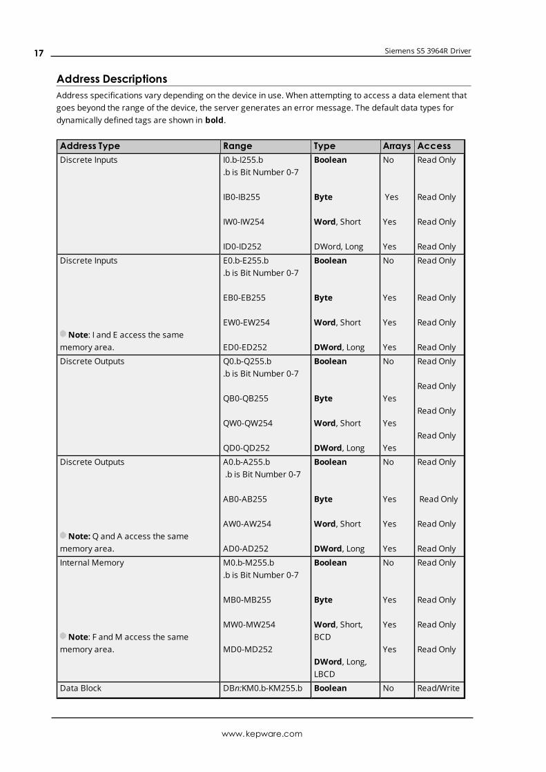
Address DescriptionsAddress specifications vary depending on the device in use. When attempting to access a data element thatgoes beyond the range of the device, the server generates an error message. The default data types fordynamically defined tags are shown in bold.
Address Type Range Type Arrays AccessDiscrete Inputs I0.b-I255.b
.b is Bit Number 0-7
IB0-IB255
IW0-IW254
ID0-ID252
Boolean
Byte
Word, Short
DWord, Long
No
Yes
Yes
Yes
Read Only
Read Only
Read Only
Read Only
Discrete Inputs
Note: I and E access the samememory area.
E0.b-E255.b.b is Bit Number 0-7
EB0-EB255
EW0-EW254
ED0-ED252
Boolean
Byte
Word, Short
DWord, Long
No
Yes
Yes
Yes
Read Only
Read Only
Read Only
Read Only
Discrete Outputs Q0.b-Q255.b.b is Bit Number 0-7
QB0-QB255
QW0-QW254
QD0-QD252
Boolean
Byte
Word, Short
DWord, Long
No
Yes
Yes
Yes
Read Only
Read Only
Read Only
Read Only
Discrete Outputs
Note:Q and A access the samememory area.
A0.b-A255.b.b is Bit Number 0-7
AB0-AB255
AW0-AW254
AD0-AD252
Boolean
Byte
Word, Short
DWord, Long
No
Yes
Yes
Yes
Read Only
Read Only
Read Only
Read Only
Internal Memory
Note: F andM access the samememory area.
M0.b-M255.b.b is Bit Number 0-7
MB0-MB255
MW0-MW254
MD0-MD252
Boolean
Byte
Word, Short,BCD
DWord, Long,LBCD
No
Yes
Yes
Yes
Read Only
Read Only
Read Only
Read Only
Data Block DBn:KM0.b-KM255.b Boolean No Read/Write
www.kepware.com
17
Siemens S5 3964R Driver
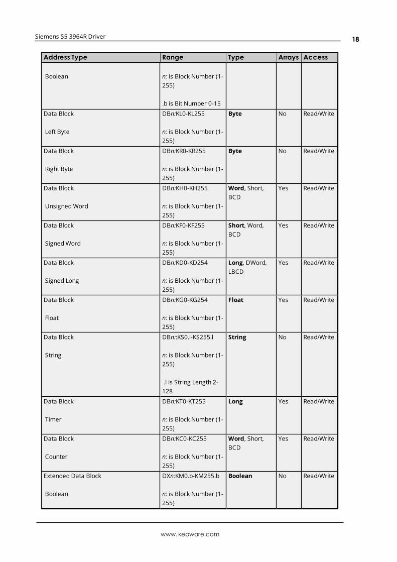
Address Type Range Type Arrays Access
Boolean n: is Block Number (1-255)
.b is Bit Number 0-15
Data Block
Left Byte
DBn:KL0-KL255
n: is Block Number (1-255)
Byte No Read/Write
Data Block
Right Byte
DBn:KR0-KR255
n: is Block Number (1-255)
Byte No Read/Write
Data Block
UnsignedWord
DBn:KH0-KH255
n: is Block Number (1-255)
Word, Short,BCD
Yes Read/Write
Data Block
SignedWord
DBn:KF0-KF255
n: is Block Number (1-255)
Short, Word,BCD
Yes Read/Write
Data Block
Signed Long
DBn:KD0-KD254
n: is Block Number (1-255)
Long, DWord,LBCD
Yes Read/Write
Data Block
Float
DBn:KG0-KG254
n: is Block Number (1-255)
Float Yes Read/Write
Data Block
String
DBn::KS0.l-KS255.l
n: is Block Number (1-255)
.l is String Length 2-128
String No Read/Write
Data Block
Timer
DBn:KT0-KT255
n: is Block Number (1-255)
Long Yes Read/Write
Data Block
Counter
DBn:KC0-KC255
n: is Block Number (1-255)
Word, Short,BCD
Yes Read/Write
Extended Data Block
Boolean
DXn:KM0.b-KM255.b
n: is Block Number (1-255)
Boolean No Read/Write
www.kepware.com
18
Siemens S5 3964R Driver
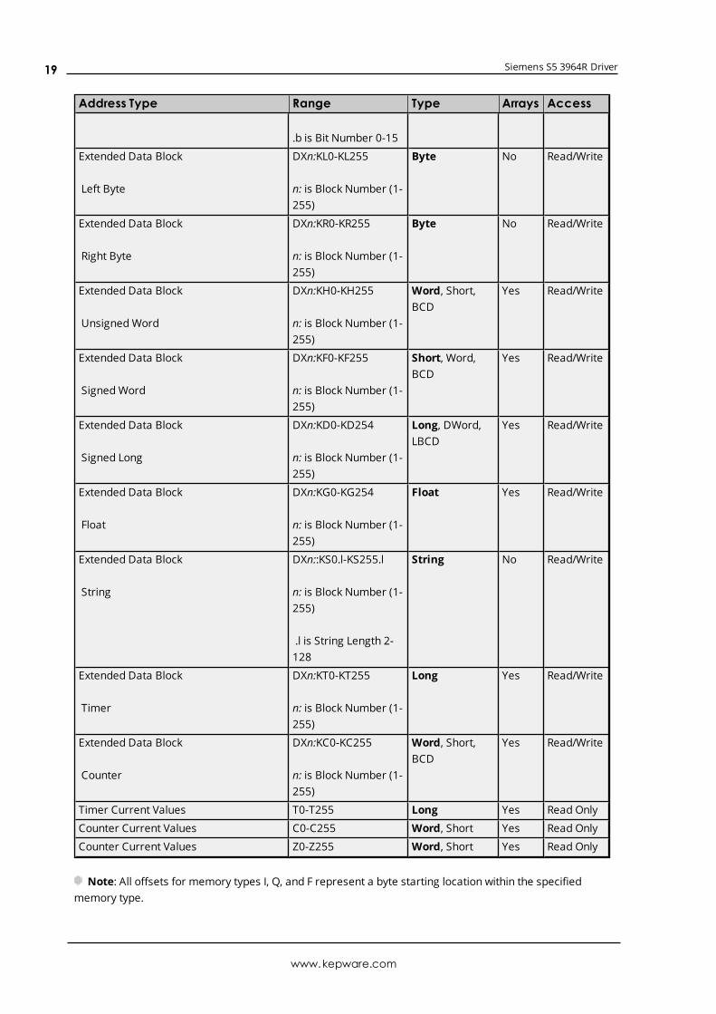
Address Type Range Type Arrays Access
.b is Bit Number 0-15
Extended Data Block
Left Byte
DXn:KL0-KL255
n: is Block Number (1-255)
Byte No Read/Write
Extended Data Block
Right Byte
DXn:KR0-KR255
n: is Block Number (1-255)
Byte No Read/Write
Extended Data Block
UnsignedWord
DXn:KH0-KH255
n: is Block Number (1-255)
Word, Short,BCD
Yes Read/Write
Extended Data Block
SignedWord
DXn:KF0-KF255
n: is Block Number (1-255)
Short, Word,BCD
Yes Read/Write
Extended Data Block
Signed Long
DXn:KD0-KD254
n: is Block Number (1-255)
Long, DWord,LBCD
Yes Read/Write
Extended Data Block
Float
DXn:KG0-KG254
n: is Block Number (1-255)
Float Yes Read/Write
Extended Data Block
String
DXn::KS0.l-KS255.l
n: is Block Number (1-255)
.l is String Length 2-128
String No Read/Write
Extended Data Block
Timer
DXn:KT0-KT255
n: is Block Number (1-255)
Long Yes Read/Write
Extended Data Block
Counter
DXn:KC0-KC255
n: is Block Number (1-255)
Word, Short,BCD
Yes Read/Write
Timer Current Values T0-T255 Long Yes Read Only
Counter Current Values C0-C255 Word, Short Yes Read Only
Counter Current Values Z0-Z255 Word, Short Yes Read Only
Note: All offsets for memory types I, Q, and F represent a byte starting location within the specifiedmemory type.
www.kepware.com
19
Siemens S5 3964R Driver
Examples
1. To access bit 3 of Internal Memory F20, declare an address as follows: F20.3
2. To access Data Block 5 as wordmemory at element 30, declare an address as follows: DB5:KH30
3. To access Data Block 2 element 20 and bit 7, declare an address as follows: DB2:KM20.7
4. To access Data Block 1 as left byte memory at element 10, declare an address as follows: DB1:KL10
5. To access Internal Memory F20 as a DWORD, declare an address as follows: FD20
6. To access Input Memory I10 as a Word, declare an address as follows: IW10
Note: Use caution whenmodifying Word, Short, DWord, and Long types. For I, Q and F each addressstarts at a byte offset within the device. Therefore, Words FW0 and FW1 overlap at byte 1. Writing to FW0also modifies the value held in FW1. Similarly, DWord, and Long types can also overlap. It is recommendedthat these memory types be used so that overlapping does not occur. When using DWords, for example,users can utilize FD0, FD4, FD8 ... and so on to prevent overlapping bytes.
TimersThe Siemens S5 3964R Driver automatically scales T and KT values based on the Siemens S5 time format.The value returned for either a T or KT memory type is already scaled using the appropriate Siemens timebase. As a result, the values are always returned as a count of milliseconds. When writing to T or KT memorytypes, the Siemens time base is applied. To write a value to a timer in the controller, simply write the desiredvalue as a count of milliseconds to the appropriate timer.
StringsString data is stored in data block registers; thus, the actual number of bytes used to store the data is aneven number. For example, if a string of length 5 is specified by DB11:KS1.5, then 3 registers (6 bytes) areused to store the string data. When writing strings shorter than the maximum specified length (5), a nullterminator (0x00) is added to the end of the string. When strings are read, the full range of registers (3) areread also. Use of string tags with overlapping address ranges should be avoided due to the effects of thenull terminators. For more information on how strings can be formatted, refer to String Options.
ArraysArrays are supported for the memory types indicated in the table above. An array can be declared using thefollowing syntax:
<address> [rows] [cols]<address> [cols]with an assumed row count of 1.
The maximum size of an array is 128 bytes, where the size of an array is calculated as follows:size = rows * cols * (data type size in bytes).
The data type size in bytes is 1 for Byte, 2 for Word and Short and 4 for DWord, Long and Float. Timers arean exception, because in that case a data size of 2 bytes should be used.
All locations referenced by an array must exist in the device. If this is not the case, the device indicates aninvalid address upon read or write and the driver deactivates the tag. For example, if data block 20 has asize of 10 words (KH0 to HK9), then:
www.kepware.com
20

Siemens S5 3964R Driver
1. DB20:KH1 [4] is valid. Element 1 references KH1, element 2 references KH2, element 3 referencesKH3 and element 4 references KH4.
2. DB20:KG1 [4] would be valid. Element 1 references KH1 and KH2, element 2 references KH3 andKH4, element 3 references KH5 and KH6 and element 4 references KH7 and KH8.
3. DB20:KH8 [4] is invalid. Element 1 references KH8, element 2 references KH9, element 3 referencesKH10 and element 4 references KH11.
Note: The last two elements reference nonexistent locations.
Counter addresses range from C0 to C255. Therefore C1 [4] is valid. C253 [4] is invalid because the lastelement references the nonexistent counter C256.
www.kepware.com
21
Siemens S5 3964R Driver
Event LogMessagesThe following information concerns messages posted to the Event Log pane in the main user interface.Consult the server help on filtering and sorting the Event Log detail view. Server help contains manycommonmessages, so should also be searched. Generally, the type of message (informational, warning)and troubleshooting information is provided whenever possible.
Read request returned error code. | Tag address = '<address>', Error code =<hex> (<decimal>).Error Type:Warning
Possible Cause:There is a problem with the read request for this device.
Possible Solution:Consult Siemens RK512 computer link documentation for specifics about this "REATEL" error code.
à Note:By allowing the device to timeout, the driver resolves an "Out of Sync" condition (REATEL code 0x36). It isnormal for this message to be followed by a "Device not responding" error.
Write request returned error code. | Tag address = '<address>', Error code =<hex> (<decimal>).Error Type:Warning
Possible Cause:There is a problem with the write request for this device.
Possible Solution:Consult Siemens RK512 computer link documentation for specifics about this "REATEL" error code.
à Note:By allowing the device to timeout, the driver resolves an "Out of Sync" condition (REATEL code 0x36). It isnormal for this message to be followed by a "Device not responding" error.
Bad block. The block has been deactivated. | Starting address = '<address>',Block size = <count> (elements).Error Type:Warning
Possible Cause:The device has been configured such that one or more of the addresses within the block is inaccessible.
Possible Solution:
www.kepware.com
22
Siemens S5 3964R Driver
1. Use different addresses.
2. Alter the device configuration.
Error Mask Definitions
B = Hardware break detectedF = Framing errorE = I/O errorO = Character buffer overrunR = RX buffer overrunP = Received byte parity errorT = TX buffer full
www.kepware.com
23
Siemens S5 3964R Driver
Index
A
Address Descriptions 17
Advanced Channel Properties 9
Auto Dial 8
B
Bad block. The block has been deactivated. | Starting address = '<address>', Block size = <count>(elements). 22
Baud 4
Baud Rate 6
C
Channel Assignment 10
Channel Properties 4
Channel Properties - General 5
Channel Properties - Write Optimizations 8
Close Idle Connection 7-8
COM ID 6
Communication Parameters 4
Communication Protocols 4
Communications Timeouts 12-13
Connect Timeout 13
Connection Type 6
CPU 14
D
Data Bits 4, 6
Data Collection 11
Data Types Description 16
Demote on Failure 14
Demotion Period 14
Description 10
www.kepware.com
24
Siemens S5 3964R Driver
Device Properties 10
Device Properties - Auto-Demotion 13
Device Properties - General 10
Diagnostics 5
Discard Requests when Demoted 14
Do Not Scan, Demand Poll Only 12
Driver 5, 11
Duty Cycle 9
E
Error Mask Definitions 23
Event Log Messages 22
F
Flag Bit 15
Flag Byte 14
Flow Control 7
I
ID 11
Idle Time to Close 7-8
IEEE-754 floating point 9
Initial Updates from Cache 12
Inter-Request Delay 13
M
Model 11
Modem 8
Modem Setup 4
N
Name 10
Network Adapter 7
www.kepware.com
25
Siemens S5 3964R Driver
Non-Normalized Float Handling 9
O
Operational Behavior 7
Optimization Method 8
Overview 3
P
Parity 4, 6
Physical Medium 6
Protocol Options 14
R
Read Processing 8
Read request returned error code. | Tag address = '<address>', Error code = <hex> (<decimal>). 22
Redundancy 15
Replace Nulls 15
Report Comm. Errors 7-8
Request All Data at Scan Rate 12
Request Data No Faster than Scan Rate 12
Request Timeout 13
Respect Client-Specified Scan Rate 12
Respect Tag-Specified Scan Rate 12
Retry Attempts 13
Reverse Byte Order 15
S
ScanMode 12
Send Full Strings 15
Serial Communications 5
Serial Port Settings 6
Setup 4
Simulated 11
Specify CPU Number in Packet 14
www.kepware.com
26
Siemens S5 3964R Driver
Specify Handshake Flag in Packet 14
Stop Bits 4, 6
String Options 15
Supported Devices 4
T
Timeouts to Demote 14
U
Unsolicited Messages 4
Use BCC (3964R) 14
W
Write All Values for All Tags 8
Write Only Latest Value for All Tags 9
Write Only Latest Value for Non-Boolean Tags 8
Write Optimizations 8
Write request returned error code. | Tag address = '<address>', Error code = <hex> (<decimal>). 22
www.kepware.com
27