sig-1135-01-17 sl7000 user guide cn0054 - … · the sl7000 logger is supplied will all ranges...
TRANSCRIPT

SL7000 User Guide
Drawing No: SIG-1135-01-17 Page 1 of 30 Change Note: CN0054
SL7000 DATA LOGGER
USER GUIDE
Signatrol.com

SL7000 User Guide
Drawing No: SIG-1135-01-17 Page 2 of 30 Change Note: CN0054
Contents 1 INTRODUCTION ............................................................................................................................................................. 3
1.1 WELCOME .................................................................................................................................................................... 3 1.2 CARE OF THE LOGGER .................................................................................................................................................. 3 1.3 UNDERSTANDING THE HARDWARE CONFIGURATION...................................................................................................... 3 1.4 SERIAL NUMBERING ..................................................................................................................................................... 3 1.5 THE DIGITAL DISPLAY ................................................................................................................................................... 3 1.6 CHANGING THE BATTERY.............................................................................................................................................. 4 1.7 LOW BATTERY WARNING. .............................................................................................................................................. 4 1.8 BATTERY LIFE............................................................................................................................................................... 5
1.8.1 Tips for extending battery life:......................................................................................................................... 5 1.8.2 Battery Life for Internal Temperature Only, Internal Humidity and Frequency.............................................. 5 1.8.3 Battery Life including 1 universal channel enabled........................................................................................ 6 1.8.4 Battery Life including 2 universal channel enabled........................................................................................ 6 1.8.5 Battery Life including 4 universal channel enabled........................................................................................ 7
1.9 RECALIBRATION............................................................................................................................................................ 8
2 SENSOR CONNECTIONS.............................................................................................................................................. 8
3 EXTERNAL POWER SUPPLY ....................................................................................................................................... 9
4 EXTERNAL TEMPERATURE/RH SENSOR.................................................................................................................. 9
5 INSTALLING TEMPIT SOFTWARE ............................................................................................................................... 9
6 COMMUNICATING WITH THE LOGGER TO THE PC ...............................................................................................10
7 FINDING THE DEVICE ................................................................................................................................................. 11
8 CONFIGURING THE LOGGER.................................................................................................................................... 11
9 REAL TIME DISPLAY ...................................................................................................................................................12
10 ISSUING THE LOGGER ...............................................................................................................................................12
10.1 FIRST ISSUE ...............................................................................................................................................................12 10.2 SETTING ALARMS .......................................................................................................................................................12 10.3 PAGE 1: GENERAL PARAMETERS ................................................................................................................................13 10.4 PAGE 2: INPUT SETUP ................................................................................................................................................14 10.5 INPUT SCALING:..........................................................................................................................................................15 10.6 COUNTER/FREQUENCY INPUT.....................................................................................................................................16 10.7 PAGE 3:MANIFEST TEXT .............................................................................................................................................17 10.8 PAGE 4: INPUT TRIM ...................................................................................................................................................17
11 STARTING THE MISSION............................................................................................................................................17
11.1 SOFTWARE START ......................................................................................................................................................17 11.2 START ON EVENT ........................................................................................................................................................17 11.3 START ON MAGNETIC SWIPE. ......................................................................................................................................17
12 DOWNLOADING DATA ................................................................................................................................................17
12.1 TO DOWNLOAD DATA:..................................................................................................................................................18
13 DISPLAYING A PREVIOUSLY STORED FILE ............................................................................................................18
14 SECURITY TIE ..............................................................................................................................................................18
15 APPENDIX.....................................................................................................................................................................19
15.1 SL7000 SPECIFICATION .............................................................................................................................................19 15.1.115.1.115.1.115.1.1 Inputs .............................................................................................................................................................19 15.1.2 Block Diagram ...............................................................................................................................................20 15.1.315.1.315.1.315.1.3 Accuracies .....................................................................................................................................................21 15.1.4 Measurement Ranges...................................................................................................................................23 15.1.5 General Specification ....................................................................................................................................23 15.1.6 Mechanical Dimensions ................................................................................................................................24 15.1.7 Optional IP65 Weather-Proof Enclosure. .....................................................................................................25 15.1.8 SL7000 Connection Overview ......................................................................................................................26 15.1.9 Current Loop Connection..............................................................................................................................27 15.1.10 Example connection from a Flow transducer with a common collector output...........................................28

SL7000 User Guide
Drawing No: SIG-1135-01-17 Page 3 of 30 Change Note: CN0054
1 Introduction
1.1 Welcome
Welcome to the SL700 data logger from Signatrol Ltd. This flexible and practical logger allows logging of up to 9 variables as follows: 1 internal temperature, 1 internal RH, 4 universal external inputs (Volts, Current, Thermocouple, RTD or Thermistor), 1 external Temperature, 1 external RH and an external count (frequency) . The number of channels available is determined by the original configuration and the software settings)
1.2 Care of the logger
The logger is housed in a rugged ABS enclosure. The internal electronics are protected against moisture ingress by a conformal coating, however, the logger is only designed to work in humid atmospheres of up to 95%RH Non- Condensing and should be protected against immersion. It should only be cleaned by wiping with a damp cloth containing a small amount of detergent. Warning! Industrial solvents and abrasives can damage the case and the front facia and should not be used for cleaning.
1.3 Understanding the Hardware Configuration
The configuration supplied is contained within the order code as shown on the rear label as follows: 1
st Digit 7 Denotes Series
2nd
Digit 0 Denotes no LCD Display, 1 denotes LCD Display fitted 3
rd Digit 0 Denotes USB connection to PC
4th Digit 0 Denotes internal temperature Only
1 Denotes internal temperature and RH 2 Denotes 2 Universal Input channels + Internal Temp 3 Denotes 2 Universal Input channels + Internal Temp + RH 4 Denotes 4 Universal Input channels + Internal Temp 5 Denotes 4 Universal Input channels + Internal Temp + RH The external Temp+ RH probe SL-ACC7000-01 can be fitted to any version. eg. SL7103 Is a SL7000 series data logger with LCD display, USB interface and two universal inputs together with an internal temperature and an internal humidity sensor.
1.4 Serial Numbering
Each device has its own unique serial number which identifies the device and enables us to keep a record of its history. This number is indelibly marked on the front label and also electronically encoded into the device. Please quote it in any correspondence.
1.5 The Digital Display
The LCD digital display option enables any measured parameter to be displayed digitally. The value together with its channel number and (in most cases*) its units are displayed. You can select which channels you want to display from the TempIT software e.g. you may choose to log say 4 channels but only to display 2. When more than one channel is selected for display the channels are cycled through at the Display Update Rate which is a programmable interval ( Default 4 Seconds). With each parameter the appropriate channel number is also displayed. *Units available are : °C,°F, mA, V, % LED Displays A separate LED is provided for each channel. When the channel is selected for logging, the LED flashes at the Display Update Rate. If the channel is in alarm it flashes RED else it flashes GREEN. An amber LED is also provided which flashes when the logger is communicating. This LED also flashes intermittently when the logger is awaiting an event start.
SL7000 User Guide
Drawing No: SIG-1135-01-17 Page 4 of 30 Change Note: CN0054
1.6 Changing the Battery
Although the battery lasts in excess of 6 years (2700mAh battery) with a 2 minute sample rate, when the battery is nearing the end of its useful life a warning message will be displayed each time you issue the logger. If the device is fitted with the LCD display option, a small battery symbol also appears in the display. The battery has approximately 1 month useful life from the logger first indicating a low battery but we recommend that the battery should be changes as soon as the warning is raised. Changing the battery will result in any data being lost but the configuration will remain. Remove the 4 stainless steel screws retaining the front half of the case and remove the front case half. The battery is now exposed and can be carefully removed from its retaining clip and replaced with a new AA size LITHIUM 3.6V 2200mAh primary cell. (Suitable replacement batteries can be obtained from your supplier). If you wish to change the battery mid-way through a mission, without aborting the mission, then this can be achieved by plugging in the USB communications port to a PC prior to removing the battery. In this mode, the PC powers the device and the battery can be safely removed without interruption to the task. The same thing can be achieved by first plugging in the external power supply. Warning! Do not use any other type of batteries as they will not work correctly and may damage the electronics. Signatrol routinely replace the battery when re-calibrating.
1.7 Low Battery warning.
The condition of the battery can be monitored from the explorer window within TempIT, and units fitted with the LCD option directly on the LCD display with a battery symbol. The low battery warning is a latched alarm. Use the following procedure to reset the warming.
� Power down the unit by removing the battery (USB not connected), when insert new battery. Warning, data will be lost if a log is currently logging.
� Insert USB from computer to logger, this will continue to provide power to the logger when the battery is removed. Remove the battery and replace with new item. The low battery warning will remain active. The next time you issue the logger, change the battery date on the issue screen. The change in battery date will clear the warning.
SL7000 User Guide
Drawing No: SIG-1135-01-17 Page 5 of 30 Change Note: CN0054
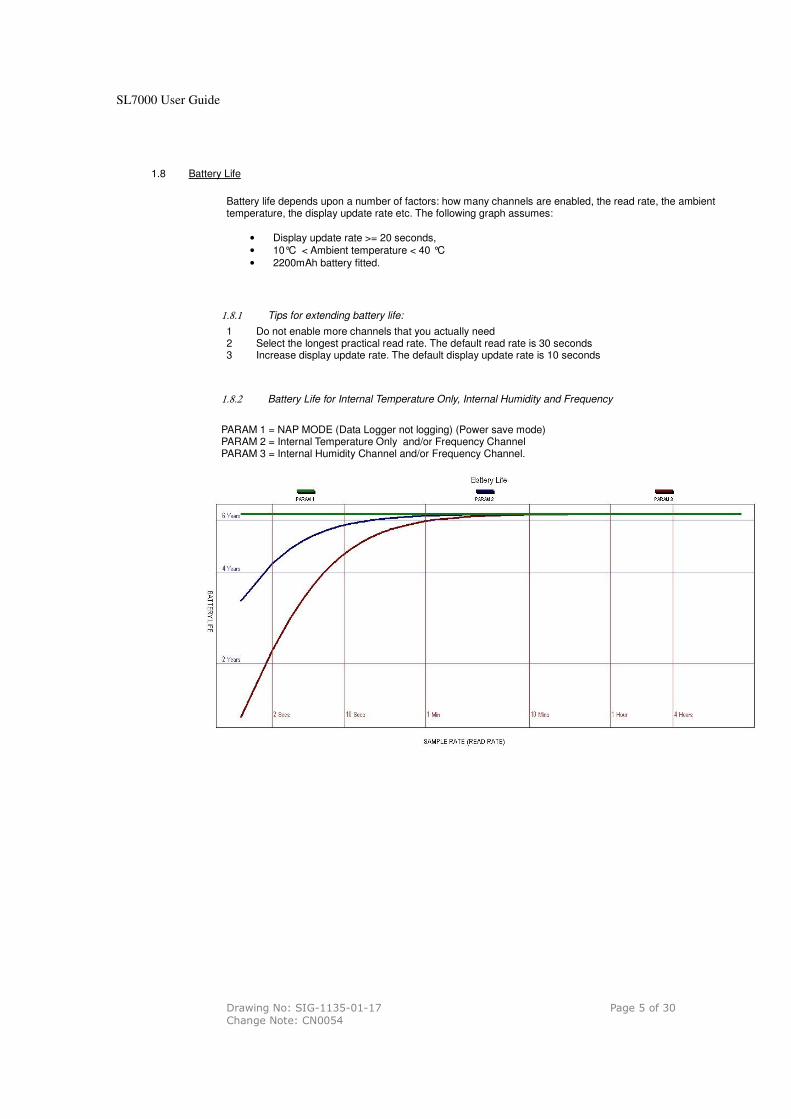
1.8 Battery Life
Battery life depends upon a number of factors: how many channels are enabled, the read rate, the ambient temperature, the display update rate etc. The following graph assumes:
• Display update rate >= 20 seconds, • 10°C < Ambient temperature < 40 °C
• 2200mAh battery fitted.
1.8.1 Tips for extending battery life:
1 Do not enable more channels that you actually need 2 Select the longest practical read rate. The default read rate is 30 seconds 3 Increase display update rate. The default display update rate is 10 seconds
1.8.2 Battery Life for Internal Temperature Only, Internal Humidity and Frequency
PARAM 1 = NAP MODE (Data Logger not logging) (Power save mode) PARAM 2 = Internal Temperature Only and/or Frequency Channel PARAM 3 = Internal Humidity Channel and/or Frequency Channel.
SL7000 User Guide
Drawing No: SIG-1135-01-17 Page 6 of 30 Change Note: CN0054
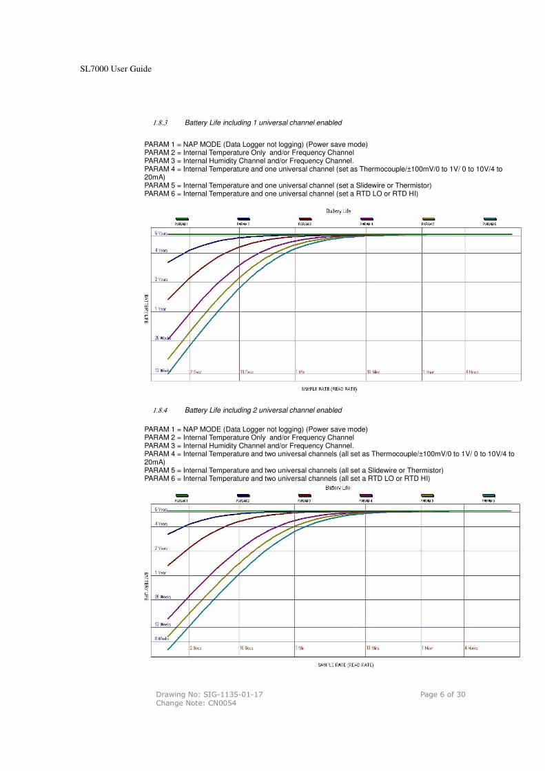
1.8.3 Battery Life including 1 universal channel enabled
PARAM 1 = NAP MODE (Data Logger not logging) (Power save mode) PARAM 2 = Internal Temperature Only and/or Frequency Channel PARAM 3 = Internal Humidity Channel and/or Frequency Channel. PARAM 4 = Internal Temperature and one universal channel (set as Thermocouple/±100mV/0 to 1V/ 0 to 10V/4 to 20mA) PARAM 5 = Internal Temperature and one universal channel (set a Slidewire or Thermistor) PARAM 6 = Internal Temperature and one universal channel (set a RTD LO or RTD HI)
1.8.4 Battery Life including 2 universal channel enabled
PARAM 1 = NAP MODE (Data Logger not logging) (Power save mode) PARAM 2 = Internal Temperature Only and/or Frequency Channel PARAM 3 = Internal Humidity Channel and/or Frequency Channel. PARAM 4 = Internal Temperature and two universal channels (all set as Thermocouple/±100mV/0 to 1V/ 0 to 10V/4 to 20mA) PARAM 5 = Internal Temperature and two universal channels (all set a Slidewire or Thermistor) PARAM 6 = Internal Temperature and two universal channels (all set a RTD LO or RTD HI)

SL7000 User Guide
Drawing No: SIG-1135-01-17 Page 7 of 30 Change Note: CN0054
1.8.5 Battery Life including 4 universal channel enabled
PARAM 1 = NAP MODE (Data Logger not logging) (Power save mode) PARAM 2 = Internal Temperature Only and/or Frequency Channel PARAM 3 = Internal Humidity Channel and/or Frequency Channel. PARAM 4 = Internal Temperature and four universal channels (all set as Thermocouple/±100mV/0 to 1V/ 0 to 10V/4 to 20mA) PARAM 5 = Internal Temperature and four universal channels (all set a Slidewire or Thermistor) PARAM 6 = Internal Temperature and four universal channels (all set a RTD LO or RTD HI)
SL7000 User Guide
Drawing No: SIG-1135-01-17 Page 8 of 30 Change Note: CN0054
1.9 Recalibration
The SL7000 logger is supplied will all ranges pre-calibrated and should not require any further re-calibration for a period of 12 months. It is possible to set a calibration reminder within the TempIT software at a selectable period, which we recommend to be no more than 12 monthly intervals. It is not possible for the user to perform a full calibration and the unit should be returned to the supplier. Signatrol offer a re-calibration service traceable to national standards.
The user can, however enter individual span and offset corrections for each channel ( See 10.8). This option is password protected to prevent un-authorised access.
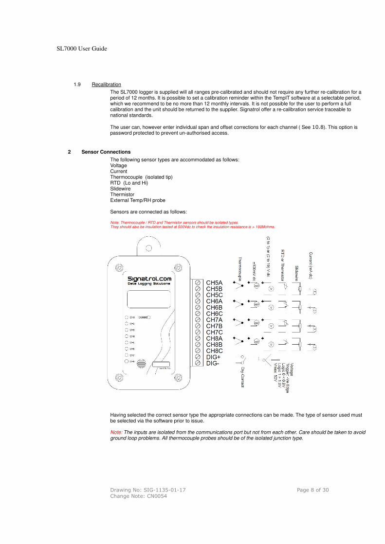
2 Sensor Connections
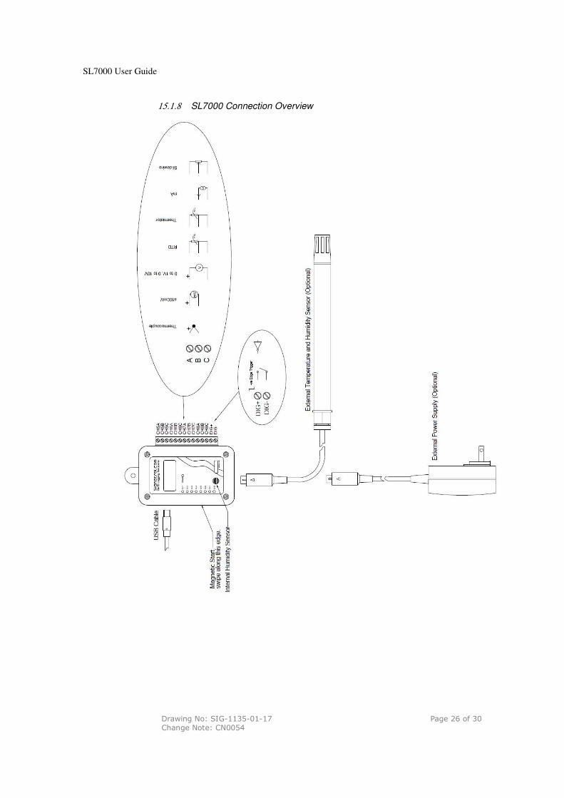
The following sensor types are accommodated as follows: Voltage Current Thermocouple (isolated tip) RTD (Lo and Hi) Slidewire Thermistor External Temp/RH probe Sensors are connected as follows: Note: Thermocouple / RTD and Thermistor sensors should be isolated types. They should also be insulation tested at 500Vdc to check the insulation resistance is > 100Mohms.
Having selected the correct sensor type the appropriate connections can be made. The type of sensor used must be selected via the software prior to issue. Note: The inputs are isolated from the communications port but not from each other. Care should be taken to avoid ground loop problems. All thermocouple probes should be of the isolated junction type.
SL7000 User Guide
Drawing No: SIG-1135-01-17 Page 9 of 30 Change Note: CN0054
3 External Power Supply
In order to provide extended battery life, especially at fast scan rates, it is possible to fit an external battery or battery eliminator. This simply plugs into the socket on the base of the unit. An appropriate power supply is available from your supplier. Warning: Only use low earth leakage power supplies, with a leakage of 10micro Amps or less.
4 External Temperature/RH sensor
The SL7000 can accept an external temperature and RH sensor which is simply plugged into the socket on the base of the unit. It is currently not possible to have both the external Temperature RH sensor and the external power supply as they share the same connector, although you could wire both into a single connector. Should you wish to de this please contact our service department for details.
5 Installing TempIT software
Warning: Ensure that the software has been installed BEFORE Connecting the logger or the Pro-Dongle (when used) to the PC. To install the software, ensure that no applications are currently running and insert the CD provided and select the ‘Install Software’ option from the menu. When the install is completed we recommend that the machine is re-started.
A new Icon will have been placed on the desk top. Note. The drivers should now have been installed automatically. After installing the software, connect the logger and the Dongle (where used) to the appropriate USB ports. Windows will now attempt to identify the devices. If Windows cannot find the appropriate drivers it will prompt you to supply the location . The default location is c:\program files\TempIT4\DRIVERS\. If the device is connected before the driver has been installed it will install as an ‘unknown device’. This must then be removed in order to perform a correct installation.
SL7000 User Guide
Drawing No: SIG-1135-01-17 Page 10 of 30 Change Note: CN0054
6 Communicating with the logger to the PC
In order to communicate with the logger, it must first be connected to a free USB port on the computer using the lead provided. The software will automatically recognise the SL7000 is present and display a message accordingly.
Double click on the icon to launch the TempIT software. The first time TempIT is started you will be asked to enter a password. This password will be used should you decide to use the security functions. Enter and make a note of a six digit password.
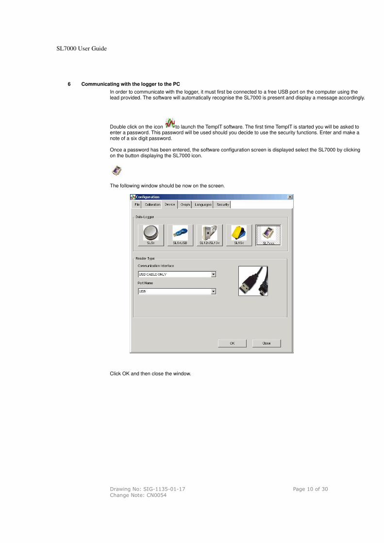
Once a password has been entered, the software configuration screen is displayed select the SL7000 by clicking on the button displaying the SL7000 icon.
The following window should be now on the screen.
Click OK and then close the window.

SL7000 User Guide
Drawing No: SIG-1135-01-17 Page 11 of 30 Change Note: CN0054
7 Finding the Device
The TempIT (Version 4 and later) software will support multiple devices and so you can use a USB hub with more that one SL7000 connected.
The first thing to do is to click on the Scan network Icon. The following screen will appear
This shows the devices, their variant code, the Location, the status and number of readings.
8 Configuring the logger
Click on the Scan network Icon right click on the device and then select ‘Configure’ Click on Configure and a number of programming pages are presented as follows:
The first screen enables general parameters to be entered. A brief summary of the parameters is listed below in 10.
Click on to set up the input parameters. Here you can select which channels you want to log and what type of sensor you have selected for the universal channels.

SL7000 User Guide
Drawing No: SIG-1135-01-17 Page 12 of 30 Change Note: CN0054
9 Real time Display
This is used to display the channels selected for logging in real time electrical units. WARNING: The displayed value is scanned initially within 1 second of the issue. The value is then updated at the selected read rate i.e if the read rate was set at 1 hour, it would be 1 hour before the realtime display would show a new reading. It is advisable to run the real time display before using the logger for the first time to check that all the channels have been set up correctly and that the sensors have been wired in correctly.
10 Issuing the Logger
Click on the Scan network Icon right click on the device and then select ‘Configure’ When the configuration is complete click issue to ‘issue’ the logger. In the first General screen set the following parameters:
10.1 First Issue
The first time the logger is issued you will be prompted to issue an ‘Owners Manifest’ and a ‘Passcode’. This is the only time you will be asked for this information and it cannot subsequently be change. The Owners manifest is a 256 character string that that is used to identify the logger. The passcode will be used to enable certain functions, restricting access to authorised personnel. Note: Make a note of the passcode and keep it in a safe place
10.2 Setting Alarms
The alarms are set at the time of the logger issue. Alarms are either high or low and have an associated time for which the channel must be continuously in alarm before the alarm is triggered. The alarm function depends upon whether or not the delayed start has been selected. If delayed start is not used then the Alarm ‘arms’ the first time the measured parameter falls within the normal band i.e. if the high alarm is set to 8 °C and the low alarm set to 2°C and the channel currently reads 20 °C the alarm will not enable until the first time the temperature falls below 8°C. This is to prevent an immediate alarm condition at issue. If delayed start is selected, the alarm becomes immediately active after the expiry of the delay. Similarly if trigger start is selected the alarm becomes immediately active. The effect of an alarm triggering is to change the colour of the LED indicator from Green to Red. An alarm condition is displayed in a number of different occurrences within the TempIT application.
1. On the USB map a device which has an active alarm will have a red background to the icon. 2. In the real-time display, each channel will be individually marked with a bell, if an active alarm is
present. 3. The graph screen will indicate alarm conditions by flashing the channel information line with the
appropriate colour.

SL7000 User Guide
Drawing No: SIG-1135-01-17 Page 13 of 30 Change Note: CN0054
10.3 Page 1: General Parameters
Serial Number: Set at Factory Location: Enter here some meaningful string of up to 12 characters to enable easy identification. Data Type: Select one of the following Point, Average, Minimum, Maximum. This defines the value that well be stored to memory. Point means that every reading will be stored, Average means the average reading will be stored etc. e.g If the read rate was set to 4 seconds and the Log Interval set to 1 minute every minute the logger would take 15 readings. If Data Type was set to Average, it will store the average of these 15 readings, If set to Maximum, it will store the maximum value etc. Read Rate: This is the rate at which the inputs are measured. It also defines the Real-time display update rate. (Default 4 seconds) Log Interval: This defines the time between stored values and is always a multiple of the Read Rate. (Default 60 seconds). The log interval can be a maximum of 255 times the read rate. Display Update: This defines the rate at which the LCD updates and scans when displaying multiple inputs. It also defines the flash rate of the LEDs The default is 4 seconds but setting this to a longer interval will improve battery life. Note: although the LCD is updated at this rate it will only have a new value after every new read i.e. if the read rate is set to 1 Minute, the LCD reading will only have a new value every minute even if the update rate is set to 4 seconds. First Reading Due: This is the current date and time as set on the PC or the date and time of the first reading when delayed start is active. This box shows ‘Trigger Start’ if either magnetic, digital start or trigger start is selected. Logger Full Expected: This box shows the date/time the logger is expected to be full when the ‘Stop when Full’ option on the right hand side of the page. It is meaningless when the @Wrap when full’ option is selected. Battery Date: Shows the date the last time the battery was changed. Delayed Start: Select this when you want to start the logger at some fixed point in the future. Magnetic Start: Select this option when you want the logger to wait for an external magnet to start it logging. Digital Start: Select this option when you want the logger to wait for the exercising of an external digital signal ( Connected to the Dig in + and – Pins of the logger) Stop When Full: Select this option if you want the logger to stop logging when the memory is full. When Full Stop Reading: Only available when “Stop When Full” selected (and Firmware SF-1017-18 and above). When selected the logger will stop measuring the inputs once the logger is full, this will give optimal battery life. If a LCD display is fitted, the display will show “FUL”. Unselecting this mode will cause the logger to continue to measure the inputs and update the LCD (if fitted) when the logger is full. Wrap when full: Select this option if you want the logger to continuously log, overwriting the oldest data when the memory becomes full. Sometimes called FIFO. Default/Custom: There are two other radio buttons labelled Default and Custom. These set the effective memory size in terms of readings per channel. Default sets the memory size to the maximum available and custom allows a smaller maximum memory size to be set,. This feature is useful when smaller amounts of data are required as it speeds up the download process

SL7000 User Guide
Drawing No: SIG-1135-01-17 Page 14 of 30 Change Note: CN0054
10.4 Page 2: Input Setup
Enabling Channels: Left Hand buttons are used to select which channels are enabled. Visual On: These buttons select the channels for display on the LCD Descriptor: Enter here a string of up to 12 characters to describe the input Input: Temperature and humidity inputs are fixed type. For universal inputs select the input type here. Linearisation: Many universal inputs have an associated linearization that can be applied. The type of linearization depends upon the type of sensor and is selected from the drop-down menu. Available linearization’s are as follows:
� Voltage, Current: Linear, SQRT, Root 3/2, Root 5/2 � RTD: EN60751, JIS1604, Ohms, Ni100, Cu100, Ni120, Cu10 � Slidewire: Linear � Thermistor: TH-001 , TH-002*, TH-003*, TH-004* � Thermocouple: K, J , R, S, N, T, B
(* dependant of firmware version)
4 to 20mA Loops: When using current loop inputs special attention is required when using non-isolated loops, this is even more critical when using more than one loop. If available always use isolated loops as this will give the
highest accuracy. See appendix for diagram about connection variations.
SL7000 User Guide
Drawing No: SIG-1135-01-17 Page 15 of 30 Change Note: CN0054
10.5 Input Scaling:
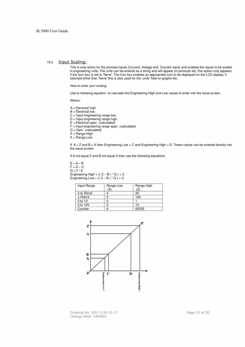
This is only active for the process inputs (Current, Voltage and Counter input) and enables the inputs to be scaled in engineering units. The units can be entered as a string and will appear on printouts etc, this option only appears if the Icon box is set to ‘None’. The Icon box enables an appropriate icon to be displayed on the LCD display, If selected other than ‘None’ this is also used for the ‘units’ field on graphs etc. How to enter your scaling. Use to following equation to calculate the Engineering High and Low values to enter into the issue screen. Where: A = Electrical high. B = Electrical low. C = Input engineering range low. D = Input engineering range high. E = Electrical span. (calculated) F = Input engineering range span. (calculated) G = Gain. (calculated) Z = Range High. X = Range Low. If A = Z and B = X then Engineering Low = C and Engineering High = D. These values can be entered directly into the issue screen. If A not equal Z and B not equal X then use the following equations. E = A – B F = D – C G = F / E Engineering High = (( Z – B ) * G ) + C Engineering Low = (( X – B ) * G ) + C
Input Range Range Low (X)
Range High (Z)
4 to 20mA 4 20
±100mV 0 100
0 to 1V 0 1 0 to 10V 0 10
Counter 0 65535
Z
A
B
X
C D
En
gin
eerin
g L
ow
?
En
gin
eering H
igh
?

SL7000 User Guide
Drawing No: SIG-1135-01-17 Page 16 of 30 Change Note: CN0054
Trigger setup: When enables, a value can be entered, in engineering units, in the High or Low box (Or both). This parameter is used to start the logger when the input first passes this transition point. i.e. if enabled and Low was set to -30 then when issued the logger will wait until a value of less that -30 was recorded on that channel before starting logging. Alarm Setup: When enabled a high and/or low alarm can be set per channel together with a time function. The time is the number of consecutive reads where an alarm condition is identified before the alarm is recognised. When an alarm is recognised, the LED on that channel changes from flashing green to flashing red. All alarms are latching. Special Condition. There is a special condition if the logger is issued (Not using delayed or trigger start) and an alarm is immediately present. In this condition, the alarm is not recognised until the channel first passes into a non-alarmed state. This effectively arms the alarm which will then trigger the next time it goes into alarm.
10.6 Counter/Frequency Input
All units have a digital input facility that can be used as a counter. The digital can be either a Potential free contact, TTL, C MOS or Open Collector transistor. The logger stores the number of counts per log interval and this is stored on channel 9. Channel 9 cannot be displayed either on the LCD or on the LED indicators. If the sample rate is set to 1 second, the counter value will represent the frequency. The unit can measure frequencies up to 32 KHz. For frequencies less that 50 Hz to prevent contact bounce giving spurious readings, it is recommended that the internal filter is activated. Setting the Internal Filter The SL 7000 has an internal filter which in enabled by the positioning of an internal jumper link. The filter is default is position ‘A’ (Off) and this is the recommended position for frequencies in excess of 50 Hz. For frequencies less than 50 Hz the recommended position is ‘B’. The filter in ‘B’ position is normally required to remove contact bounce from potential free contact inputs. To obtain access to the jumper remove the 4 stainless steel screws from the front of the unit. The jumper is then visible close to the edge connector.
SL7000 User Guide
Drawing No: SIG-1135-01-17 Page 17 of 30 Change Note: CN0054
10.7 Page 3:Manifest Text
Here the Owners Name is displayed. This is entered the first time the logger is issued and cannot later be changed. It also provides for the entry of up to 256 characters of manifest text which form part of the record and are used to record useful information relating to the test run, shipment, application etc.
10.8 Page 4: Input Trim
This requires a password entry to ensure authorised access. The password is the passcode entered the first time the TempIT application was installed. The Input Trim enables custom calibrations to be entered in terms of offset and span corrections. This is not normally necessary and is normally only used in special applications. Span and Offset correction values are entered for each channel. Span is a gain correction around a nominal gain of 1 and offset is entered in Electrical units. Limits are:
Span 0.95 to 1.05 Offset + 5
Warning: setting input trim values will change the calibration of the measured variables and may result in in-accurate readings.
11 Starting the Mission
There are thee ways to start the mission
11.1 Software start
If none of the other options have been selected that the logger will start as soon immediately the issue button is pressed unless a delayed start has been entered. The delayed start is some future time when the logger will commence logging.
11.2 Start on event
An event can be one of two things. It can be the exercising of a remote digital connected to the digital input or any one of the inputs where a trigger event has been set. The logger will wait with the orange LED blinking, for the event. As soon as the log commences, the orange LED extinguishes and the appropriate Green/Red channel LEDs start blinking.
Digital start is selected in the general parameters screen see 10.3 and trigger start parameters are entered in the
input setup screen see 10.4. If multiple events are set that the logger will start at the first event.
11.3 Start on Magnetic swipe.
If Start on Magnetic swipe has been selected, the logger will wait with the orange LED blinking, for a magnetic swipe. The magnet is applied at the position indicated on the rear label. As soon as the log commences, the orange LED ceases blinking and the appropriate Green/Red channel LEDs start blinking.
12 Downloading Data
After a successful issue the logger will store data according to the parameters entered. At the end of the test the data are then down-loaded to the PC for display and analysis.
SL7000 User Guide
Drawing No: SIG-1135-01-17 Page 18 of 30 Change Note: CN0054
12.1 To download data:
Click on the Scan network Icon right click on the device and then select ‘Download’ The Data are then downloaded and immediately displayed on the screen in Graphical format. This can take up to 2 minutes for a full logger with the full memory. The buttons down the side of the graph are self explanatory and are used to manipulate the graph to the desired format. The cursor on the graph can be moved with the mouse and displays time/date and value in the text to the top of the graph. ‘Export Data’ and ‘Show Table’ are features that are only available in TempIT-Pro Note: TempIT-Lite only allows up to two channels to be displayed on the graph at any one time with only two axes. For unlimited multiple traces and up to six different axes the upgrade to TempIT-Pro is required. Consult your supplier. Further information on the TempIT software is contained in the TempIT manual. The SL7000 will only work with TempIT version 4 and later. The Lite version of this can be downloaded free of charge fro out web site
www.signatrol.com
13 Displaying a previously stored file
Close down all the screens until you are left with the blank home page. Click on ‘File’ and ‘Open Graph file’ (Or alternatively the open file icon )
A list of previously stored files will be presented. Double click on the file you wish to open. More information can be found on displaying and manipulating graphs in the TempIT manual and the on screen help.
14 Security Tie
All our data loggers are equipped with a mounting hole. This is designed to accept a standard security tie which is used to ensure that the logger is not tampered with. The security ties are for single use and must be cut off to remove. Each tie has a unique serial number which should be noted and/or programmed into the Tag manifest. In this way, the user can be sure that the Tag has not been moved from its intended location without the operator knowing. Spare security ties are available from the company.

SL7000 User Guide
Drawing No: SIG-1135-01-17 Page 19 of 30 Change Note: CN0054
15 Appendix
15.1 SL7000 Specification
15.1.115.1.115.1.115.1.1 Inputs
Description Detail
Input Variations SL7000 Internal Temperature and counter (SL7100 inc LCD display) SL7001 Internal Temperature + RH and counter (SL7101 inc LCD display) SL7002 Internal Temperature, 2 Channel Universal and counter (SL7102 inc LCD display) SL7003 Internal Temperature + RH, 2 Channel Universal and counter (SL7103 inc LCD display) SL7004 Internal Temperature, 4 Channel Universal and counter (SL7104 inc LCD display) SL7005 Internal Temperature, RH, 4 Channel Universal and counter (SL7105 inc LCD display) +Additional External Temp and RH option on all versions
Universal Input (maximum 4) Narrow Range*2: Pt 100: 2 or 3 Wire °C or °F (BS EN 60751/JIS1604) Ni100, Ni120: 2 or 3 Wire °C or °F Cu100, Cu10: 2 or 3 Wire °C or °F Ohms 2 or 3 Wire Wide Range Pt 100: 2 or 3 Wire °C or °F (BS EN 60751/JIS1604) Ni100, Ni120: 2 or 3 Wire °C or °F Cu100 2 or 3 Wire °C or °F Ohms 2 or 3 Wire Standard Ranges Thermocouples Types J, K, T, R, S, B, N °C or °F *2 Thermistor Types TH-001, TH-002, TH-003, TH-004*1, °C or °F (4 to 20) mA Scaled in engineering units ±100mVdc Scaled in engineering units (0 to 1)Vdc Scaled in engineering units (0 to 10) Vdc Scaled in engineering units Slidewire Scaled in engineering units (100 ohm to 10Kohm) Shunt required if R>350 ohms. *2 When connecting temperature probes, ensure they that the sensors are isolated from all conductive parts of the probe. The probe should me isolated tested @ 500Vdc for a insulation resistance of > 500 Mega ohms.
* TH-004 available on firmware version 17 or greater.
*NARROW RANGE ON FIRMWARE VERSION 22 or greater
Measurement Resolution All Universal Inputs - 16 Bit1 (Sample Period 20mS) Internal & External Temperature - 12 Bit Internal & External Relative Humidity - 8 Bit
Cross-Talk between adjacent channels > 100 dB
Counter Input Used to start logging or as a counter. Maximum Count = 65535 per sample period. A Voltage > 1.9V is a logic ‘1’ and a voltage < 0.9V is a logic ‘0’. Counts can be actual counts or scaled in engineering units. Maximum frequency = 32768Hz. A Logic ‘0’ enables the digital start feature. Absolute maximum input voltage ±50V. An external shunt resistor maybe required when connecting to open collector outputs. See section 15.1.10
Read Rate 1 Second to 24 hours for all channels ( Default 10 Seconds) Logger sample rates will increase battery life.
Sample Methods Point - The sampled measurement is stored directly to memory. Averaging - The average value per period is stored Maximum - The maximum value per period is stored Minimum - The maximum value per period is stored
Start Options Start Immediately Programmable Delay Period (10 minutes to 1 year) Start on external magnet swipe Start when counter input goes low Start on event trigger
Channel Indicators 8 Green LED's to indicate logging status changing to Red to indicate alarm conditions
Communication Indicator 1 Yellow LED to indicate comms activity and waiting to start
Display Optional 3.5 Digit LCD with channel indication and low battery warning. Continuous display with value updated every 2 to 255 seconds (Default 4 Seconds). Units displayable are °C, °F, mA, V, %
Communication Interface USB Isolated (Mini-USB 1B Male connector) – 1 Metre Cable Supplied
Universal Input Connector 14 Way 2 part plug/socket
External Temperature & RH Connector 6 Pin Mini-Din
Cold Junction Compensation Uses internal temperature sensor
SL7000 User Guide
Drawing No: SIG-1135-01-17 Page 20 of 30 Change Note: CN0054
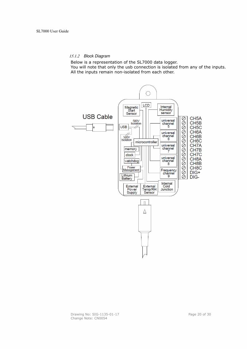
15.1.2 Block Diagram
Below is a representation of the SL7000 data logger.
You will note that only the usb connection is isolated from any of the inputs.
All the inputs remain non-isolated from each other.
SL7000 User Guide
Drawing No: SIG-1135-01-17 Page 21 of 30 Change Note: CN0054
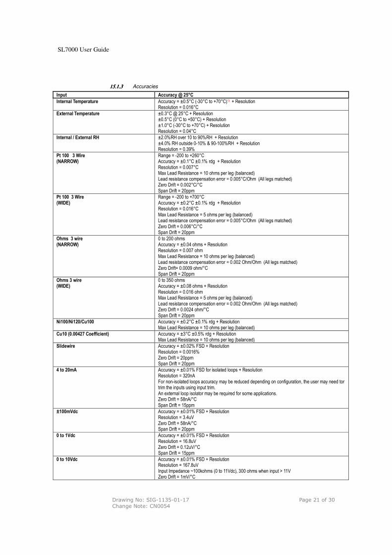
15.1.315.1.315.1.315.1.3 Accuracies
Input Accuracy @ 25°C
Internal Temperature Accuracy = ±0.5°C (-30°C to +70°C)*3 + Resolution Resolution = 0.016°C
External Temperature ±0.3°C @ 25°C + Resolution ±0.5°C (0°C to +50°C) + Resolution ±1.0°C (-30°C to +70°C) + Resolution Resolution = 0.04°C
Internal / External RH ±2.0%RH over 10 to 90%RH + Resolution ±4.0% RH outside 0-10% & 90-100%RH + Resolution Resolution = 0.39%
Pt 100 3 Wire (NARROW)
Range = -200 to +260°C Accuracy = ±0.1°C ±0.1% rdg + Resolution Resolution = 0.007°C Max Lead Resistance = 10 ohms per leg (balanced) Lead resistance compensation error = 0.005°C/Ohm (All legs matched) Zero Drift = 0.002°C/°C Span Drift = 20ppm
Pt 100 3 Wire (WIDE)
Range = -200 to +700°C Accuracy = ±0.2°C ±0.1% rdg + Resolution Resolution = 0.016°C Max Lead Resistance = 5 ohms per leg (balanced) Lead resistance compensation error = 0.005°C/Ohm (All legs matched) Zero Drift = 0.006°C/°C Span Drift = 20ppm
Ohms 3 wire (NARROW)
0 to 200 ohms Accuracy = ±0.04 ohms + Resolution Resolution = 0.007 ohm Max Lead Resistance = 10 ohms per leg (balanced) Lead resistance compensation error = 0.002 Ohm/Ohm (All legs matched) Zero Drift= 0.0009 ohm/°C Span Drift = 20ppm
Ohms 3 wire (WIDE)
0 to 350 ohms Accuracy = ±0.08 ohms + Resolution Resolution = 0.016 ohm Max Lead Resistance = 5 ohms per leg (balanced) Lead resistance compensation error = 0.002 Ohm/Ohm (All legs matched) Zero Drift = 0.0024 ohm/°C Span Drift = 20ppm
Ni100/Ni120/Cu100 Accuracy = ±0.2°C ±0.1% rdg + Resolution Max Lead Resistance = 10 ohms per leg (balanced)
Cu10 (0.00427 Coefficient) Accuracy = ±3°C ±0.5% rdg + Resolution Max Lead Resistance = 10 ohms per leg (balanced)
Slidewire Accuracy = ±0.02% FSD + Resolution Resolution = 0.0016% Zero Drift = 20ppm Span Drift = 20ppm
4 to 20mA Accuracy = ±0.01% FSD for isolated loops + Resolution Resolution = 320nA For non-isolated loops accuracy may be reduced depending on configuration, the user may need tor trim the inputs using input trim. An external loop isolator may be required for some applications. Zero Drift = 58nA/°C Span Drift = 15ppm
±100mVdc Accuracy = ±0.01% FSD + Resolution Resolution = 3.4uV Zero Drift = 58nA/°C Span Drift = 20ppm
0 to 1Vdc Accuracy = ±0.01% FSD + Resolution Resolution = 16.8uV Zero Drift = 0.12uV/°C Span Drift = 15ppm
0 to 10Vdc Accuracy = ±0.01% FSD + Resolution Resolution = 167.8uV Input Impedance ~100kohms (0 to 11Vdc), 300 ohms when input > 11V Zero Drift = 1mV/°C

SL7000 User Guide
Drawing No: SIG-1135-01-17 Page 22 of 30 Change Note: CN0054
Span Drift = 15ppm
Thermocouples J, K, T, N (°C or °F)
Accuracy = ±0.1% FSD + CJ error (±0.5°C) + Resolution Resolution = 0.035°C Cold Junction Tracking = 0.02°C/°C Zero Drift = 0.1uV/°C Span Drift = 15ppm
Thermocouples R, S, B (°C or °F)
Accuracy = ±0.2% FSD + CJ error (±0.5°C) + Resolution Resolution = 0.035°C Cold Junction Tracking = 0.02°C/°C Zero Drift = 0.1uV/°C Span Drift = 15ppm
Thermistor TH-001 (SenTech IN-K010K-C214) (10K @ 25°C) Accuracy: ±0.5°C + Resolution Resolution = 0.016°C TH-002 (Vishay 2381-640-6151) (150R @ 25°C) Accuracy: ±0.6 ( 0 to +70°C), ±1.2 ( -30 to +90°C) + Resolution Resolution = 0.016°C TH-003 (Vishay 2381-640-6223) (22K @ 25°C) Accuracy: ±0.5°C + Resolution Resolution = 0.016°C TH-004* (Semitec 103AP-2) (10K @ 25°C, B25/85 = 3435K, Tol ±0.5%) Accuracy: ±0.5°C (0 to +70°C), ±0.8°C (-40 to +105°C) + Resolution Resolution = 0.016°C Type dependent contact sales office for details. * TH-004 available on firmware version 17 or greater.
*3 When connected to the USB port of the PC, the unit is powered from the port. This results in a temperature rise within the unit of approximately 1 °C. Specification subject to change without notice.
SL7000 User Guide
Drawing No: SIG-1135-01-17 Page 23 of 30 Change Note: CN0054
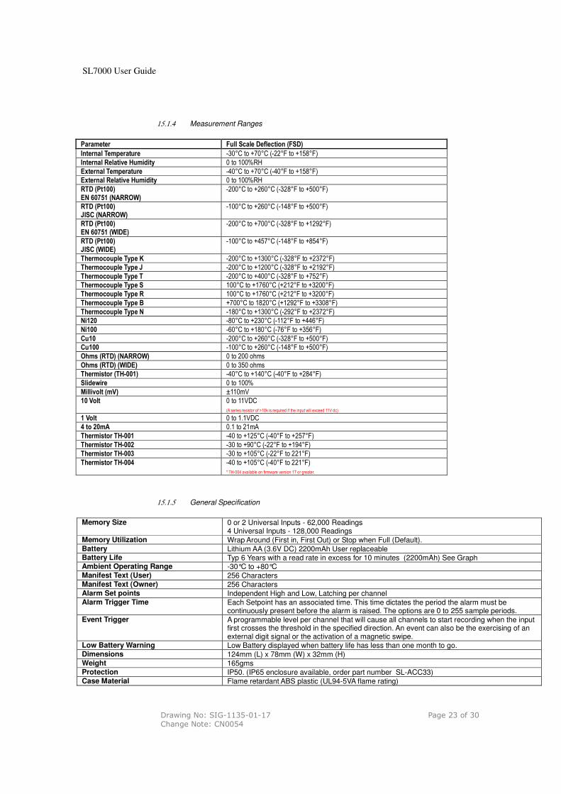
15.1.4 Measurement Ranges
Parameter Full Scale Deflection (FSD)
Internal Temperature -30°C to +70°C (-22°F to +158°F)
Internal Relative Humidity 0 to 100%RH
External Temperature -40°C to +70°C (-40°F to +158°F)
External Relative Humidity 0 to 100%RH
RTD (Pt100) EN 60751 (NARROW)
-200°C to +260°C (-328°F to +500°F)
RTD (Pt100) JISC (NARROW)
-100°C to +260°C (-148°F to +500°F)
RTD (Pt100) EN 60751 (WIDE)
-200°C to +700°C (-328°F to +1292°F)
RTD (Pt100) JISC (WIDE)
-100°C to +457°C (-148°F to +854°F)
Thermocouple Type K -200°C to +1300°C (-328°F to +2372°F)
Thermocouple Type J -200°C to +1200°C (-328°F to +2192°F)
Thermocouple Type T -200°C to +400°C (-328°F to +752°F)
Thermocouple Type S 100°C to +1760°C (+212°F to +3200°F)
Thermocouple Type R 100°C to +1760°C (+212°F to +3200°F)
Thermocouple Type B +700°C to 1820°C (+1292°F to +3308°F)
Thermocouple Type N -180°C to +1300°C (-292°F to +2372°F)
Ni120 -80°C to +230°C (-112°F to +446°F)
Ni100 -60°C to +180°C (-76°F to +356°F)
Cu10 -200°C to +260°C (-328°F to +500°F)
Cu100 -100°C to +260°C (-148°F to +500°F)
Ohms (RTD) (NARROW) 0 to 200 ohms
Ohms (RTD) (WIDE) 0 to 350 ohms
Thermistor (TH-001) -40°C to +140°C (-40°F to +284°F)
Slidewire 0 to 100%
Millivolt (mV) ±110mV
10 Volt 0 to 11VDC
(A series resistor of >10k is required if the input will exceed 11V dc)
1 Volt 0 to 1.1VDC
4 to 20mA 0.1 to 21mA
Thermistor TH-001 -40 to +125°C (-40°F to +257°F)
Thermistor TH-002 -30 to +90°C (-22°F to +194°F)
Thermistor TH-003 -30 to +105°C (-22°F to 221°F)
Thermistor TH-004 -40 to +105°C (-40°F to 221°F)
* TH-004 available on firmware version 17 or greater.
15.1.5 General Specification
Memory Size 0 or 2 Universal Inputs - 62,000 Readings
4 Universal Inputs - 128,000 Readings Memory Utilization Wrap Around (First in, First Out) or Stop when Full (Default). Battery Lithium AA (3.6V DC) 2200mAh User replaceable Battery Life Typ 6 Years with a read rate in excess for 10 minutes (2200mAh) See Graph Ambient Operating Range -30°C to +80°C Manifest Text (User) 256 Characters Manifest Text (Owner) 256 Characters Alarm Set points Independent High and Low, Latching per channel Alarm Trigger Time
Each Setpoint has an associated time. This time dictates the period the alarm must be continuously present before the alarm is raised. The options are 0 to 255 sample periods.
Event Trigger A programmable level per channel that will cause all channels to start recording when the input first crosses the threshold in the specified direction. An event can also be the exercising of an external digit signal or the activation of a magnetic swipe.
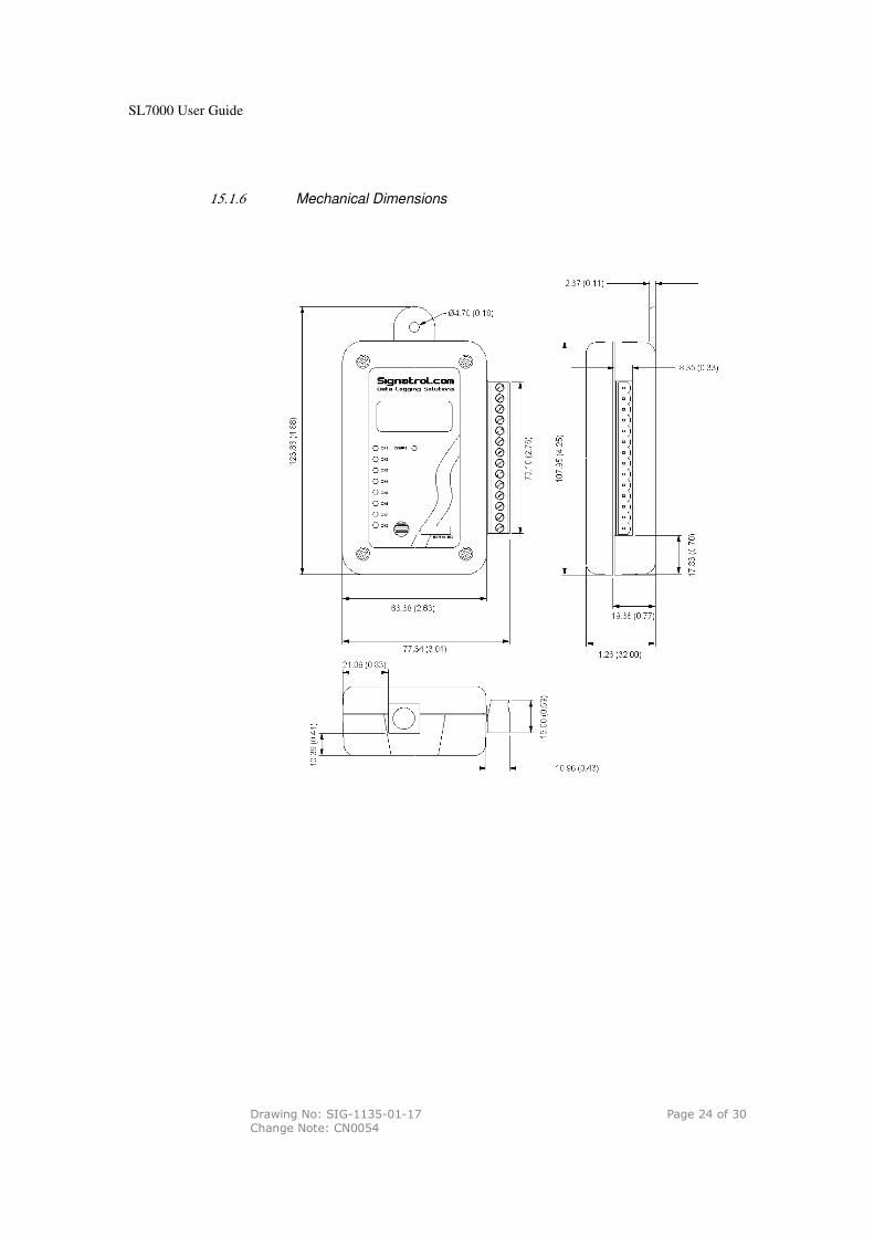
Low Battery Warning Low Battery displayed when battery life has less than one month to go. Dimensions 124mm (L) x 78mm (W) x 32mm (H) Weight 165gms Protection IP50. (IP65 enclosure available, order part number SL-ACC33) Case Material Flame retardant ABS plastic (UL94-5VA flame rating)
SL7000 User Guide
Drawing No: SIG-1135-01-17 Page 24 of 30 Change Note: CN0054
15.1.6 Mechanical Dimensions

SL7000 User Guide
Drawing No: SIG-1135-01-17 Page 25 of 30 Change Note: CN0054
15.1.7 Optional IP65 Weather-Proof Enclosure.
Part Number: SL-ACC33
Polycarbonate with clear cover NEMA rated/waterproof enclosure for
outdoors, weatherproof. UL94-HB flame rating
SL7000 User Guide
Drawing No: SIG-1135-01-17 Page 26 of 30 Change Note: CN0054
15.1.8 SL7000 Connection Overview

SL7000 User Guide
Drawing No: SIG-1135-01-17 Page 27 of 30 Change Note: CN0054
15.1.9 Current Loop Connection

SL7000 User Guide
Drawing No: SIG-1135-01-17 Page 28 of 30 Change Note: CN0054
15.1.10 Example connection from a Flow transducer with a common collector output.
SL7000 User Guide
Drawing No: SIG-1135-01-17 Page 29 of 30 Change Note: CN0054
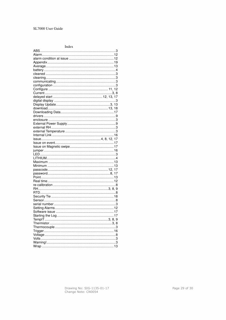
Index
ABS.................................................................................3 Alarm.............................................................................12 alarm condition at issue ................................................12 Appendix.......................................................................19 Average.........................................................................13 battery.............................................................................4 cleaned ...........................................................................3 cleaning...........................................................................3 communicating................................................................3 configuration ...................................................................3 Configure ................................................................ 11, 12 Current ........................................................................3, 8 delayed start .....................................................12, 13, 17 digital display ..................................................................3 Display Update..........................................................3, 13 download.................................................................13, 18 Downloading Data.........................................................17 drivers .............................................................................9 enclosure ........................................................................3 External Power Supply....................................................9 external RH .....................................................................3 external Temperature ......................................................3 Internal Link ..................................................................16 issue................................................................4, 8, 12, 17 Issue on event...............................................................17 Issue on Magnetic swipe...............................................17 jumper ...........................................................................16 LED.................................................................................3 LITHIUM..........................................................................4 Maximum ......................................................................13 Minimum .......................................................................13 passcode.................................................................12, 17 password...................................................................8, 17 Point..............................................................................13 Real time.......................................................................12 re-calibration ...................................................................8 RH...........................................................................3, 8, 9 RTD.................................................................................8 Security Tie ...................................................................18 Sensor.............................................................................8 serial number ..................................................................3 Setting Alarms...............................................................12 Software issue ..............................................................17 Starting the Log.............................................................17 TempIT....................................................................3, 8, 9 Thermistor...................................................................3, 8 Thermocouple .................................................................3 Trigger...........................................................................16 Voltage ............................................................................8 Volts ................................................................................3 Warning!..........................................................................3 Wrap .............................................................................13
SL7000 User Guide
Drawing No: SIG-1135-01-17 Page 30 of 30 Change Note: CN0054
This Apparatus conforms with:-
The protection requirements of Council Directive 89/336/EEC on the approximation of the laws of
Member States relating to electromagnetic compatibility {Article 10 (1)}, as amended by Council
Directives 92/31/EEC, 93/68/EEC and changes.
STANDARD:- BS EN 61326;1998 IEC 61326:1997
Electrical Equipment for measurement, control and laboratory use EMC
requirements.
IMMUNITY ANNEX A (Industrial Locations) EMISSIONS CLASS B
If all else fails call us on 01684 299 399
Signatrol Ltd Unit E2, Green Lane Business Park,
Tewkesbury,
Gloucestershire,
GL20 8SJ, UK
DISCLAIMER: WHILST WE AT SIGNATROL LTD TAKE PRIDE IN THE PERFORMANCE AND ACCURACY OF OUR PRODUCTS, ANY PRODUCT CAN AND WILL FAIL. IT IS THEREFORE RECOMMENDED THAT ALL PRODUCTS ARE REGULARLY CHECKED FOR PERFORMANCE AND CALIBRATION AND THAT ANY APPLICATION WHICH INVOLVES THE HEALTH AND/OR SAFETY OF PERSONS, ANIMALS OR OTHER LIVING ORGANISMS SHOULD HAVE A SECONDARY SYSTEM AND THE CUSTOMER SHOULD NOT RELY ON THE DATA FROM THE PRODUCT ALONE.
THE COMPANY SHALL NOT BE LIABLE FOR ANY CONSEQUENTIAL LOSS OR DAMAGE, COSTS, EXPENSES OR OTHER CLAIMS FOR CONSEQUENTIAL COMPENSATION OR ANY OTHER CLAIMS FOR INDIRECT OR ECONOMIC LOSS WHATSOEVER WHICH ARISE OUT OF OR IN CONNECTION WITH ANY ORDER FOR THE SUPPLY OF THE GOODS AND/OR THE PROVISION OF THE SERVICES.
THE COMPANY’S LIABILITY FOR DAMAGE TO TANGIBLE PROPERTY RESULTING FROM BREACH OF CONTRACT AND/OR ANY NEGLIGENT ACT OR OMISSION OF THE COMPANY OR ITS EMPLOYEES, AGENTS OR SUB-CONTRACTORS SHALL BE LIMITED TO £5,000,000 IN RESPECT OF ANY ONE INCIDENT OR £5,000,000 IN RESPECT OF ANY SERIES OF INCIDENTS ARISING FROM A COMMON CAUSE.
FULL DETAILS OF THE EXTENT OF THE COMPANY’S LIABILITY ARE CONTAINED IN THE TERMS AND CONDITIONS OF SALE AVAILABLE ON REQUEST OR FROM OUR WEB SITE WWW.SIGNATROL.COM.