signal conditioning extensions for instrumentation conditioning extensions for instrumentation this...
TRANSCRIPT

SCXI Quick Start GuideSignal Conditioning eXtensions for Instrumentation
This document contains English, French, and German language instructions. For Japanese, Korean, and Simplified Chinese language instructions, refer to the other document in your kit.
Ce document contient des instructions en anglais, français et allemand. Pour les consulter en japonais, coréen et chinois simplifié, reportez-vous à l’autre document dans votre kit.
Dieses Dokument enthält Anleitungen auf Englisch, Französisch und Deutsch. Anleitungen auf Japanisch, Koreanisch und in vereinfachtem Chinesisch finden Sie in dem anderen Dokument in diesem Kit.
This document explains how to install and configure SCXI signal conditioning modules in SCXI-1000, SCXI-1001, SCXI-1000DC, or PXI/SCXI combination chassis, confirm the module and chassis are operating properly, and set up multichassis systems. It also describes the NI-DAQmx software relative to SCXI and integrated signal conditioning products. This document assumes you have already installed, configured, and tested your NI application and driver software, and the data acquisition (DAQ) device to which you will connect the SCXI module. If you have not, refer to the DAQ Getting Started guides included with the DAQ device and available on the NI-DAQ software media and from ni.com/manuals, before continuing.
For instructions on configuring Traditional NI-DAQ (Legacy), refer to the Traditional NI-DAQ (Legacy) Readme after you have installed the software. Refer to the NI Switches Getting Started Guide, available at ni.com/manuals, for switch information.
Step 1. Unpack the Chassis, Module, and AccessoriesRemove the chassis, module, and accessory from the packaging and inspect the products for loose components or any sign of damage. Notify NI if the products appear damaged in any way. Do not install a damaged device.
™
SCXI Quick Start Guide 2 ni.com
For safety and compliance information, refer to the device documentation packaged with your device, at ni.com/manuals, or the NI-DAQmx media that contains device documentation.
The following symbols may be on your device.
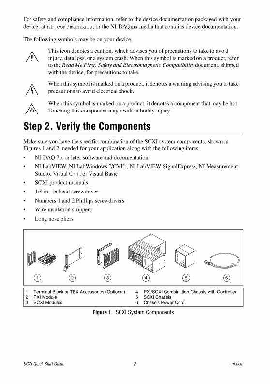
Step 2. Verify the ComponentsMake sure you have the specific combination of the SCXI system components, shown in Figures 1 and 2, needed for your application along with the following items:
• NI-DAQ 7.x or later software and documentation
• NI LabVIEW, NI LabWindows™/CVI™, NI LabVIEW SignalExpress, NI Measurement Studio, Visual C++, or Visual Basic
• SCXI product manuals
• 1/8 in. flathead screwdriver
• Numbers 1 and 2 Phillips screwdrivers
• Wire insulation strippers
• Long nose pliers
Figure 1. SCXI System Components
This icon denotes a caution, which advises you of precautions to take to avoid injury, data loss, or a system crash. When this symbol is marked on a product, refer to the Read Me First: Safety and Electromagnetic Compatibility document, shipped with the device, for precautions to take.
When this symbol is marked on a product, it denotes a warning advising you to take precautions to avoid electrical shock.
When this symbol is marked on a product, it denotes a component that may be hot. Touching this component may result in bodily injury.
1 Terminal Block or TBX Accessories (Optional)2 PXI Module3 SCXI Modules
4 PXI/SCXI Combination Chassis with Controller5 SCXI Chassis6 Chassis Power Cord
1
C 17 18 19 20 21 22 23 24 25 26 27 28 29 30 31 32 C
V 1 2 3 4 5 6 7 8 9 10 11 12 13 14 15 16 V
63
SCXI
1140
5
®
MAINFRAME
SCXI
54321
POWER
RESET
AD
DR
ES
S
2 4 63 52 4 63 52 4
© National Instruments Corporation 3 SCXI Quick Start Guide
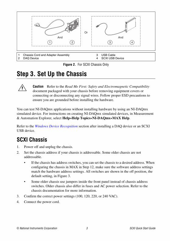
Figure 2. For SCXI Chassis Only
Step 3. Set Up the Chassis
Caution Refer to the Read Me First: Safety and Electromagnetic Compatibility document packaged with your chassis before removing equipment covers or connecting or disconnecting any signal wires. Follow proper ESD precautions to ensure you are grounded before installing the hardware.
You can test NI-DAQmx applications without installing hardware by using an NI-DAQmx simulated device. For instructions on creating NI-DAQmx simulated devices, in Measurement & Automation Explorer, select Help»Help Topics»NI-DAQmx»MAX Help.
Refer to the Windows Device Recognition section after installing a DAQ device or an SCXI USB device.
SCXI Chassis1. Power off and unplug the chassis.
2. Set the chassis address if your chassis is addressable. Some older chassis are not addressable.
• If the chassis has address switches, you can set the chassis to a desired address. When configuring the chassis in MAX in Step 12, make sure the software address settings match the hardware address settings. All switches are shown in the off position, the default setting, in Figure 3.
• Some older chassis use jumpers inside the front panel instead of chassis address switches. Older chassis also differ in fuses and AC power selection. Refer to the chassis documentation for more information.
3. Confirm the correct power settings (100, 120, 220, or 240 VAC).
4. Connect the power cord.
1 Chassis Cord and Adapter Assembly2 DAQ Device
3 USB Cable4 SCXI USB Device
1 2
And
Or
And
43

SCXI Quick Start Guide 4 ni.com
Figure 3. SCXI Chassis Setup
PXI/SCXI Combination ChassisYou must have a system controller installed in the PXI side of the chassis. Refer to ni.com/info and type rdfis5 to order a configured PXI/SCXI combination chassis.
1. Power off both the PXI and SCXI power switches, and unplug the chassis.
2. Set the SCXI chassis address switch positions to the desired address. In Figure 4, all switches are shown in the off position.
3. Set the voltage selection tumbler to the correct voltage for your application. Refer to the chassis documentation for more information.
4. Connect the power cord.
Figure 4. PXI/SCXI Combination Chassis Setup
1 Front2 Back
3 Chassis Power Switch4 Chassis Address Switch
5 Voltage Selection Tumbler6 Power Cord Connector
1 Front2 Back3 Voltage Selection Tumbler
4 Power Cord Connector5 Address Switch6 SCXI Power Switch
7 PXI Power Switch8 System Controller
AD
DR
ES
S
ON
54321
SCXI
120Vac~®
54321
POWER
RESET
AD
DR
ES
S
1 2
5
6
4
3
SCXI
120Vac~
AD
DR
ES
S
ON
54321
21
8
5
3
4
67
© National Instruments Corporation 5 SCXI Quick Start Guide
Step 4. Install the Modules
Caution Make sure the chassis is completely powered off. SCXI modules are not hot-swappable. Adding or removing modules while the chassis is powered on can result in blown chassis fuses or damage to the chassis and modules.
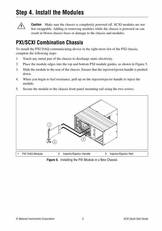
PXI/SCXI Combination ChassisTo install the PXI DAQ communicating device in the right-most slot of the PXI chassis, complete the following steps:
1. Touch any metal part of the chassis to discharge static electricity.
2. Place the module edges into the top and bottom PXI module guides, as shown in Figure 5.
3. Slide the module to the rear of the chassis. Ensure that the injector/ejector handle is pushed down.
4. When you begin to feel resistance, pull up on the injector/ejector handle to inject the module.
5. Secure the module to the chassis front panel mounting rail using the two screws.
Figure 5. Installing the PXI Module in a New Chassis
1 PXI DAQ Module 2 Injector/Ejector Handle 3 Injector/Ejector Rail
3
1
2
SCXI Quick Start Guide 6 ni.com
SCXI Chassis1. Touch any metal part of the chassis to discharge static electricity.
2. Insert the module into the SCXI slot.
3. Secure the module to the chassis front panel mounting rail using the two thumbscrews.
Figure 6. Installing the SCXI Module in a New Chassis
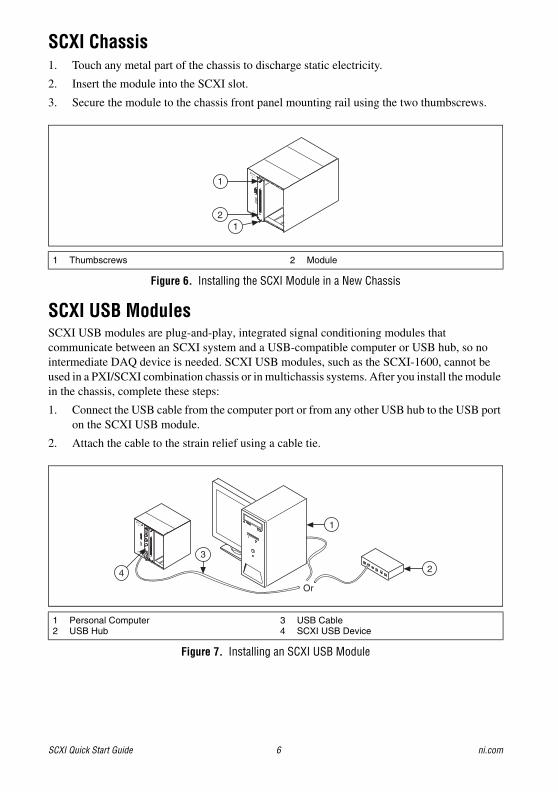
SCXI USB ModulesSCXI USB modules are plug-and-play, integrated signal conditioning modules that communicate between an SCXI system and a USB-compatible computer or USB hub, so no intermediate DAQ device is needed. SCXI USB modules, such as the SCXI-1600, cannot be used in a PXI/SCXI combination chassis or in multichassis systems. After you install the module in the chassis, complete these steps:
1. Connect the USB cable from the computer port or from any other USB hub to the USB port on the SCXI USB module.
2. Attach the cable to the strain relief using a cable tie.
Figure 7. Installing an SCXI USB Module
1 Thumbscrews 2 Module
1 Personal Computer2 USB Hub
3 USB Cable4 SCXI USB Device
®
54321
1
21
Or
®
54321
AD
DR
ES
S
4
3
2
1

© National Instruments Corporation 7 SCXI Quick Start Guide
Add a Module to an Existing SCXI SystemYou also can add a module to an existing SCXI system in multiplexed mode. If your system already has a controller established, install additional SCXI modules in any available chassis slots. Refer to Step 7. Install the Cable Adapter to determine which module to connect to the cable adapter, if applicable.
Figure 8. Installing the SCXI Module in an Existing System
Step 5. Attach Sensors and Signal LinesAttach sensors and signal lines to the terminal block, accessory, or module terminals for each installed device. The following table lists device terminal/pinout locations.
For information about sensors, refer to ni.com/sensors. For information about IEEE 1451.4 TEDS smart sensors, refer to ni.com/teds.
1 New SCXI Module2 Existing SCXI Module
3 SCXI Chassis4 Existing DAQ Device
Location How to Access Pinout
MAX Right-click the device name under Devices and Interfaces, and select Device Pinouts.
Right-click the device name under Devices and Interfaces, and select Help»Online Device Documentation. A browser window opens to ni.com/manuals with the results of a search for relevant device documents.
DAQ Assistant Select the task or virtual channel, and click the Connection Diagram tab. Select each virtual channel in the task.
NI-DAQmx Help Select Start»All Programs»National Instruments»NI-DAQ»NI-DAQmx Help.
ni.com/manuals
Refer to the device documentation.
ON
8
1234567
12
91011
ADDR
ESS
BAUD
1
3
2
4

SCXI Quick Start Guide 8 ni.com
Step 6. Attach the Terminal Blocks
SCXI Chassis or PXI/SCXI Combination ChassisIf you installed direct-connect modules, skip to Step 7. Install the Cable Adapter.
Attach the terminal blocks to the front of the modules. Refer to ni.com/products to determine valid terminal block and module combinations. If you are using a TBX terminal block, refer to its guide.
Figure 9. Attaching Terminal Blocks
Step 7. Install the Cable Adapter
Single-Chassis SystemIf you installed an SCXI USB module, such as the SCXI-1600, or are using a PXI/SCXI combination chassis, skip to Step 9. Power On the SCXI Chassis.
1. Identify the appropriate SCXI module to connect to the cable adapter, such as the SCXI-1349. If there is an analog input module with simultaneous sampling capability in the chassis, you must connect that module to the cable assembly, or an error message appears each time you run your application.
• If all modules are in multiplexed mode, determine which of the modules occurs first in the following list, and attach the cable adapter to it:
• If your system has both parallel and multiplexed modules, select the multiplexed controller from the previous list, and attach the cable adapter to it.
1 Modules with Installed Terminal Blocks2 Attaching a Terminal Block to the SCXI Module
3 SCXI Module Front Panels
SCXI-1520, SCXI-1530, SCXI-1531, SCXI-1540, SCXI-1140
SCXI-1521/B, SCXI-1112, SCXI-1102/B/C, SCXI-1104/C, SCXI-1125, SCXI-1126, SCXI-1141, SCXI-1142, SCXI-1143, SCXI-1581
SCXI-1120/D, SCXI-1121, SCXI-1100, SCXI-1122
SCXI-1124, SCXI-116x
®
54321
AD
DR
ES
S
1
23

© National Instruments Corporation 9 SCXI Quick Start Guide
• If all modules are in parallel mode, attach a cable adapter to each module. The following modules can run in parallel mode:
2. Insert the 50-pin female connection on the rear of the cable adapter into the 50-pin male connector on the rear of the appropriate SCXI module.
Caution Do not force the adapter if there is resistance. Forcing the adapter can bend pins.
3. Fasten the adapter to the rear of the SCXI chassis with the screws provided with the SCXI-1349.
Figure 10. Installing the Cable Adapter
Multichassis SystemThe SCXI-1346 covers the rear connector of two modules. When viewing the chassis from the rear, the module to the right of the module directly connected to the SCXI-1346 cannot have an external cable inserted into its rear 50-pin connector.
SCXI-1000 chassis through revision D do not have address jumpers or switches and respond to any address, but you cannot use them in multichassis systems. Revision E chassis use jumpers on Slot 0 for chassis addressing. Revision F and later chassis use a DIP switch for chassis addressing.
SCXI-1000DC chassis through revision C do not have address jumpers or switches and respond to any address, but you cannot use them in multichassis systems. Revision D and later chassis use jumpers on Slot 0 for chassis addressing.
SCXI-1001 chassis through revision D use jumpers on Slot 0 for chassis addressing. Revision E and later chassis use a DIP switch for chassis addressing.
SCXI-1120/D, SCXI-1121, SCXI-1125, SCXI-1126, SCXI-1140, SCXI-1141, SCXI-1142, SCXI-1143, SCXI-1520, SCXI-1530, SCXI-1531
1 SCXI Chassis2 SCXI-1349 Cable Adapter
3 68-Pin Shielded Cable4 Screws
1
3
2
4
4
FUSE
PULL
SCXI Quick Start Guide 10 ni.com
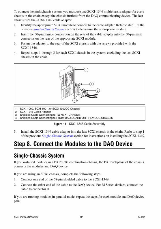
To connect the multichassis system, you must use one SCXI-1346 multichassis adapter for every chassis in the chain except the chassis furthest from the DAQ communicating device. The last chassis uses the SCXI-1349 cable adapter.
1. Identify the appropriate SCXI module to connect to the cable adapter. Refer to step 1 of the previous Single-Chassis System section to determine the appropriate module.
2. Insert the 50-pin female connection on the rear of the cable adapter into the 50-pin male connector on the rear of the appropriate SCXI module.
3. Fasten the adapter to the rear of the SCXI chassis with the screws provided with the SCXI-1346.
4. Repeat steps 1 through 3 for each SCXI chassis in the system, excluding the last SCXI chassis in the chain.
Figure 11. SCXI-1346 Cable Assembly
5. Install the SCXI-1349 cable adapter into the last SCXI chassis in the chain. Refer to step 1 of the previous Single-Chassis System section for instructions on installing the SCXI-1349.
Step 8. Connect the Modules to the DAQ Device
Single-Chassis SystemIf you installed modules in a PXI/SCXI combination chassis, the PXI backplane of the chassis connects the modules and DAQ device.
If you are using an SCXI chassis, complete the following steps:
1. Connect one end of the 68-pin shielded cable to the SCXI-1349.
2. Connect the other end of the cable to the DAQ device. For M Series devices, connect the cable to connector 0.
If you are running modules in parallel mode, repeat the steps for each module and DAQ device pair.
1 SCXI-1000, SCXI-1001, or SCXI-1000DC Chassis2 SCXI-1346 Cable Adapter3 Shielded Cable Connecting to TO NEXT CHASSIS4 Shielded Cable Connecting to FROM DAQ BOARD OR PREVIOUS CHASSIS
1
3
2
4
FUSE
PULL
TO
NE
XT
CH
AS
SIS
FR
OM
DA
Q B
OA
RD
OR
PR
EV
IOU
S C
HA
SS
IS
SC
XI-1
34
6S
HIE
LD
ED
MU
LT
I-CH
AS
SIS
AD
AP
TE
RTOP

© National Instruments Corporation 11 SCXI Quick Start Guide
Multichassis System1. Connect one end of a 68-pin shielded cable to the DAQ communicating device.
2. Connect the other end of the cable to the SCXI-1346 in chassis ID n labeled FROM DAQ BOARD OR PREVIOUS CHASSIS.
3. Connect a 68-pin shielded cable to the SCXI-1346 in chassis n labeled TO NEXT CHASSIS.
4. Connect the other end of the cable to the SCXI-1346 in chassis ID n+1 labeled FROM DAQ BOARD OR PREVIOUS CHASSIS.
5. Repeat steps 3 and 4 for the remaining chassis until you reach the last chassis.
6. Connect the 68-pin shielded cable to the next to the last chassis in the slot labeled TO NEXT CHASSIS.
7. Connect the other end of the cable to the SCXI-1349 in the last chassis.
Figure 12. Completed SCXI System
Step 9. Power On the SCXI ChassisIf you are using an SCXI chassis, the chassis power switch is shown in Figure 3. If you are using a PXI/SCXI combination chassis, the PXI and chassis power switches are shown in Figure 4.
When the controller recognizes a USB device such as an SCXI-1600 module, the LED on the module front panel blinks or lights up. Refer to the device documentation for LED pattern descriptions and troubleshooting information.
Windows Device RecognitionWindows versions earlier than Windows Vista recognize any newly installed device when the computer restarts. Vista installs device software automatically. If the Found New Hardware wizard opens, Install the software automatically as recommended for each device.
1 Shielded Cable Connected to SCXI-1349 Cable Adapter
2 Shielded Cable Connected to SCXI-1346 Cable Adapter
3 DAQ Device
4 Shielded Cable to DAQ Device
5 Terminal Blocks
6 Sensors7 SCXI Chassis
HV–
+
V–
+
mV–
+
3
1
2
4
5
6
7
HV–
+
V–
+
mV–
+
SCXI Quick Start Guide 12 ni.com
NI Device MonitorAfter Windows detects newly installed NI USB devices, NI Device Monitor runs automatically at startup.
Make sure the NI Device Monitor icon, shown at left, is visible in the taskbar notification area. Otherwise, the NI Device Monitor does not open. To turn the NI Device Monitor on, unplug your device, restart NI Device Monitor by selecting Start»All Programs»National Instruments»NI-DAQ»NI Device Monitor, and plug in your device.
The NI Device Monitor prompts you to select from the following options. These options may vary, depending on the devices and software installed on your system.
• Begin a Measurement with This Device Using NI LabVIEW SignalExpress—Opens an NI-DAQmx step that uses the channels from your device in LabVIEW SignalExpress.
• Begin an Application with This Device—Launches LabVIEW. Choose this option if you have already configured your device in MAX.
• Run Test Panels—Launches MAX test panels for your device.
• Configure and Test This Device—Opens MAX.
• Take No Action—Recognizes your device but does not launch an application.
The following features are available by right-clicking the NI Device Monitor icon:
• Run at Startup—Runs NI Device Monitor at system startup (default).
• Clear All Device Associations—Select to clear all actions set by the Always Take This Action checkbox in the device auto-launch dialog box.
• Close—Turns off NI Device Monitor. To turn on NI Device Monitor, select Start»All Programs»National Instruments»NI-DAQ»NI Device Monitor.
Step 10. Confirm That the Chassis and Modules Are RecognizedComplete the following steps:
1. Double-click the Measurement & Automation icon on the desktop to open MAX.
2. Expand Devices and Interfaces to confirm your device is detected. If you are using a remote RT target, expand Remote Systems, find and expand your target, and then expand Devices and Interfaces.

© National Instruments Corporation 13 SCXI Quick Start Guide
If your device is not listed, press <F5> to refresh MAX. If the device is still not recognized, refer to ni.com/support/daqmx.
Step 11. Add the Chassis
Identify the PXI ControllerIf you are using a PXI/SCXI combination chassis, complete the following steps to identify the embedded PXI controller installed in your chassis.
1. Right-click PXI System and select Identify As. If you are using a remote RT target, expand Remote Systems, find and expand your target, and then right-click PXI System.
2. Select the PXI controller from the list.
Add the SCXI ChassisIf you installed an SCXI USB module, such as the SCXI-1600, skip to Step 12. Configure the Chassis and Modules. The SCXI USB module and associated chassis appear automatically under Devices and Interfaces.
To add the chassis, complete the following steps.
1. Right-click Devices and Interfaces and select Create New. If you are using a remote RT target, expand Remote Systems, find and expand your target, right-click Devices and Interfaces, and select Create New. The Create New window opens.
2. Select the SCXI chassis. 3. Click Finish.
1 When a device is supported by both Traditional NI-DAQ (Legacy) and NI-DAQmx and both are installed, the same device is listed with a different name under My System»Devices and Interfaces.
2 Only NI-DAQmx devices are listed under Remote Systems»Devices and Interfaces.
2
1

SCXI Quick Start Guide 14 ni.com
Alternatively, you can right-click Devices and Interfaces and select your chassis from New» NI-DAQmx SCXI Chassis.
Step 12. Configure the Chassis and ModulesIf you are configuring a chassis with an SCXI-1600, right-click the chassis, select Properties, and skip to step 6 of this section. The SCXI-1600 auto-detects all other modules.
Complete the following steps as shown in the figures. Numbered callouts in the figures correspond to the step numbers.
1. Select the DAQ device cabled to the communicating SCXI module from Chassis Communicator. If MAX detects only one DAQ device, the device is chosen by default, and this option is disabled.
2. Select the module slot connected to the chassis communicator from Communicating SCXI Module Slot.
3. Enter the chassis address setting in Chassis Address. Make sure the setting matches the address setting on the SCXI chassis.
4. Select whether to auto-detect SCXI modules. If you do not auto-detect modules, MAX disables Communicating SCXI Module Slot.
5. Click Save. The SCXI Chassis Configuration window opens. The Modules tab is selected by default.
2
5
3
1
4
6
7
9
8
© National Instruments Corporation 15 SCXI Quick Start Guide
6. If you did not auto-detect modules, select an SCXI module from the Module Array listbox. Be sure to specify the module in the correct slot.
7. Click in the Device Identifier field and enter a unique alphanumeric ID to change the name of the SCXI module. MAX provides a default name for the Device Identifier.
8. If you are using a connected accessory, specify it in Accessory.
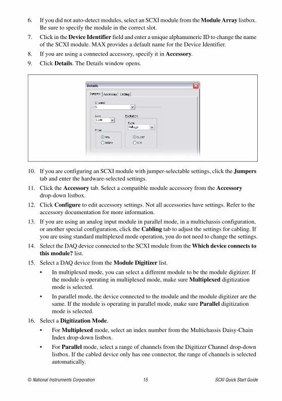
9. Click Details. The Details window opens.
10. If you are configuring an SCXI module with jumper-selectable settings, click the Jumpers tab and enter the hardware-selected settings.
11. Click the Accessory tab. Select a compatible module accessory from the Accessory drop-down listbox.
12. Click Configure to edit accessory settings. Not all accessories have settings. Refer to the accessory documentation for more information.
13. If you are using an analog input module in parallel mode, in a multichassis configuration, or another special configuration, click the Cabling tab to adjust the settings for cabling. If you are using standard multiplexed mode operation, you do not need to change the settings.
14. Select the DAQ device connected to the SCXI module from the Which device connects to this module? list.
15. Select a DAQ device from the Module Digitizer list.
• In multiplexed mode, you can select a different module to be the module digitizer. If the module is operating in multiplexed mode, make sure Multiplexed digitization mode is selected.
• In parallel mode, the device connected to the module and the module digitizer are the same. If the module is operating in parallel mode, make sure Parallel digitization mode is selected.
16. Select a Digitization Mode.
• For Multiplexed mode, select an index number from the Multichassis Daisy-Chain Index drop-down listbox.
• For Parallel mode, select a range of channels from the Digitizer Channel drop-down listbox. If the cabled device only has one connector, the range of channels is selected automatically.
SCXI Quick Start Guide 16 ni.com
Note Some M Series devices have two connectors. You must select the range of channels that corresponds to the connector cabled to the module. Channels 0–7 correspond to connector 0. Channels 16–23 correspond to connector 1.
Caution If you remove a chassis from a daisy chain, reassign the index values for modules in other chassis. Reassigning values maintains consistency and prevents addressing removed chassis.
17. Click OK to accept the settings, close the Details window, and return to the SCXI Chassis Configuration window.
18. If you installed more than one module, repeat the configuration process from step 6 by selecting the appropriate SCXI module from the next Module Array listbox.
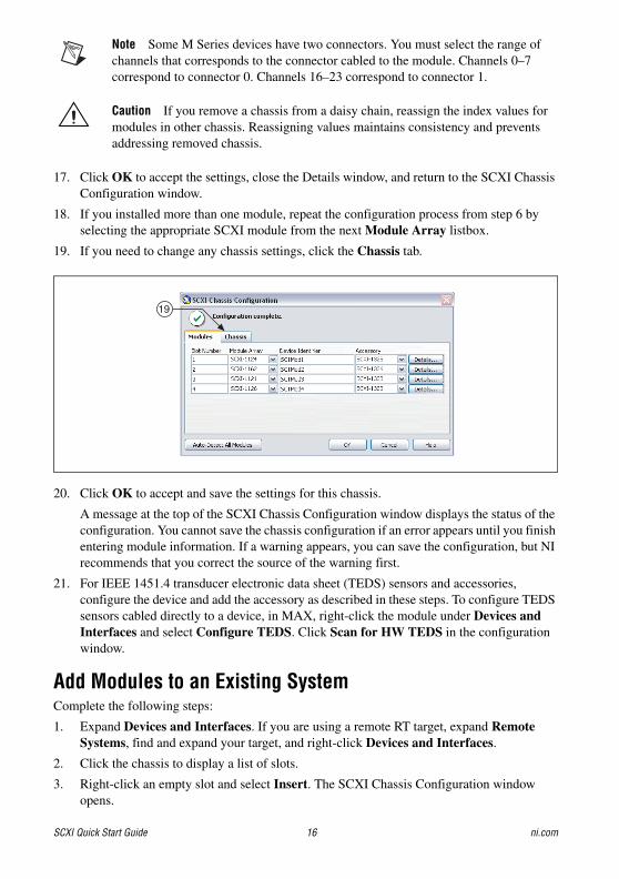
19. If you need to change any chassis settings, click the Chassis tab.
20. Click OK to accept and save the settings for this chassis.
A message at the top of the SCXI Chassis Configuration window displays the status of the configuration. You cannot save the chassis configuration if an error appears until you finish entering module information. If a warning appears, you can save the configuration, but NI recommends that you correct the source of the warning first.
21. For IEEE 1451.4 transducer electronic data sheet (TEDS) sensors and accessories, configure the device and add the accessory as described in these steps. To configure TEDS sensors cabled directly to a device, in MAX, right-click the module under Devices and Interfaces and select Configure TEDS. Click Scan for HW TEDS in the configuration window.
Add Modules to an Existing SystemComplete the following steps:
1. Expand Devices and Interfaces. If you are using a remote RT target, expand Remote Systems, find and expand your target, and right-click Devices and Interfaces.
2. Click the chassis to display a list of slots.
3. Right-click an empty slot and select Insert. The SCXI Chassis Configuration window opens.
19

© National Instruments Corporation 17 SCXI Quick Start Guide
4. Click Auto-Detect All Modules and Yes.
5. Starting with step 6 from Step 12. Configure the Chassis and Modules, begin configuration of the module.
6. Test the chassis, as described in Step 13. Test the Chassis.
Step 13. Test the Chassis1. Expand Devices and Interfaces.
2. Right-click the name of the chassis to test.
3. Select Test to verify that MAX recognizes the chassis. A message explains when the chassis is not recognized.
To test the successful installation of each module, right-click the module you want to test and click Test Panels. When the SCXI-1600 is tested, it verifies the entire SCXI system. The Error Details box displays any errors the test encounters. The module icon in the device tree is green if you have successfully installed the module. The SCXI system should now operate properly. Close the test panel.
Test NI-DAQmx applications without installing hardware using NI-DAQmx simulated SCXI chassis and modules, excluding the SCXI-1600. Refer to the Measurement & Automation Explorer Help for NI-DAQmx by selecting Help»Help Topics»NI-DAQ»MAX Help for NI-DAQmx for instructions about creating NI-DAQmx simulated devices and importing NI-DAQmx simulated device configurations to physical devices.
If the previous self-test did not verify that the chassis is properly configured and working, check the following to troubleshoot the SCXI configuration:
• If the Verify SCXI Chassis message box opens showing the SCXI chassis model number, Chassis ID: x, and one or more messages stating Slot Number: x Configuration has module: SCXI-XXXX or 1600, hardware in chassis is: Empty, take the following troubleshooting actions:
– Make sure the SCXI chassis is powered on.
– Make sure all SCXI modules are properly installed in the chassis as previously described.
– Make sure the USB cable between the SCXI-1600 and the computer is properly connected.
• After checking the preceding items, retest the SCXI chassis.
• If the SCXI-1600 is not detected, complete the following steps:
1. Press <F5> to refresh MAX.
2. Verify that the SCXI-1600 Ready LED is bright green. If the LED is not bright green, power off the chassis, wait five seconds, and power on the chassis.
If these steps do not successfully configure the SCXI system, contact NI Technical Support at ni.com/support for assistance.

SCXI Quick Start Guide 18 ni.com
Step 14. Take an NI-DAQmx MeasurementThis step applies only if you are programming your device using NI-DAQ or NI application software. Refer to Take an NI-DAQmx Measurement in the DAQ Getting Started Guide for information.
Use Your Task in an ApplicationRefer to the DAQ Getting Started Guide for information.
TroubleshootingThis section contains troubleshooting tips and answers to questions that SCXI users commonly ask NI technical support staff.
TipsBefore you contact NI, try the following troubleshooting tips:
• If you have problems installing your software, go to ni.com/support/daqmx. For hardware troubleshooting, go to ni.com/support, enter your device name, or go to ni.com/kb.
• Go to ni.com/info and enter rddq8x for a complete listing of NI-DAQmx documents and their locations.
• If you need to return your National Instruments hardware for repair or device calibration, refer to ni.com/info and enter the info code rdsenn to start the Return Merchandise Authorization (RMA) process.
• Make sure the SCXI chassis is powered on. If you are using a PXI/SCXI combination chassis, make sure the PXI chassis is powered on.
• Make sure you have installed the latest version of the NI-DAQ driver software that supports the devices in your system.
• If MAX cannot establish communication with the chassis, try one or all of the following:
– Connect the DAQ device to a different module in the chassis.
– Try a different cable assembly.
– Try a different chassis.
– Try a different DAQ device.
• Make sure that each SCXI chassis connected to a single DAQ device has a unique address.
• Make sure that the cable is securely connected to the chassis.
• Check for bent pins on the module, chassis backplane, and the device connector.
• If you have multiple SCXI modules, remove all the modules and test each module individually.
• If you are getting erroneous readings from the signal source, disconnect the signal source and short-circuit the input channel to ground. You should get a 0 V reading. Alternatively, connect a battery or other known signal source to the input channel.
• Run an example program to see if you still get erroneous results.

© National Instruments Corporation 19 SCXI Quick Start Guide
Frequently Asked QuestionsMy chassis is powered on, and my modules are configured for multiplexed mode, but I am not getting good data on any channel. What is causing this problem?
The SCXI chassis has backplane fuses, fused at 1.5 A on the SCXI-1000 chassis and at 4 A on the SCXI-1001 chassis. One or both of the fuses might be blown.
On the SCXI-1600, you can determine whether the fuses are blown by looking at the power LEDs. Both power LEDs on the SCXI-1600 and the LED on the chassis must be lit. If any of the LEDs are not lit, one or both fuses are blown.
On the SCXI-1000, the backplane fuses are located behind the fan. On the SCXI-1001, the backplane fuses are located behind the right-hand fan, near the power entry module, as viewed from the rear of the chassis.
Complete the following steps to examine and/or replace fuses.
1. Power off the chassis and remove the power cord.
2. Remove the four screws that secure the fan and filter to the rear of the chassis. When removing the last screw, be careful to hold the fan to avoid breaking the fan wires.
3. To determine whether a fuse is blown, connect an ohmmeter across the leads. If the reading is not approximately 0 Ω, replace the fuse. The fuse marked with a copper + on the backplane is for the positive analog supply, and the fuse marked with a copper – is for the negative analog supply.
4. Using long-nose pliers, carefully remove the fuse.
5. Take a new fuse and bend its leads so the component is 12.7 mm (0.5 in.) long—the dimension between the fuse sockets—and clip the leads to a length of 6.4 mm (0.25 in.).
6. Using long-nose pliers, insert the fuse into the socket holes.
7. Repeat steps 3 through 6, if necessary, for the other fuse.
8. Align the fan and filter with the fan holes, making sure that the label side of the fan is face down. Reinstall the four screws and make sure the assembly is secure.
Refer to the chassis user manuals for fuse specifications.
My chassis worked until I inadvertently removed and reinserted a module while the chassis was powered on. Now my chassis does not power on. What can I do?
SCXI modules are not hot-swappable, so you might have blown a chassis fuse. If replacing the fuse does not correct the problem, you might have damaged the digital bus circuitry or the SCXI module. Contact NI Technical Support at ni.com/support for assistance.
MAX does not recognize my chassis when I perform a test. What can I do?
Check the following items:
• Verify the chassis is powered on.
• Verify the chassis is correctly cabled to a DAQ device. If more than one DAQ device is installed in your PC, verify the device selected for Chassis Communicator is actually connected to the chassis.
• Check backplane pins to determine if any were bent during installation of the modules.

SCXI Quick Start Guide 20 ni.com
• Verify correct placement and configuration of the modules. If you did not auto-detect modules, modules installed in the chassis may not be configured in software. Alternately, modules configured in software might not match the ones installed in the chassis.
All my channels float to a positive rail when I try to take a measurement. How do I correct the problem?
Make sure that the signal reference settings for the DAQ device match the SCXI module. For example, if the device is configured for NRSE, make sure that the cabled SCXI module shares the same configuration. Matching configurations can require a change to the jumper setting of the module.
I am using one of the following modules—SCXI-1100, SCXI-1102/B/C, SCXI-1112, or SCXI-1125—with one of the following terminal blocks—SCXI-1300, SCXI-1303, or SCXI-1328—to measure temperature with a thermocouple. How do I stop the thermocouple reading from fluctuating?
Average the temperature readings to minimize fluctuations. Also, ensure proper field wiring techniques. Most thermocouples are floating signal sources with low common-mode voltage; they require a path for bias currents from the SCXI module amplifier to ground. Make sure that you have grounded the negative lead of each floating thermocouple through a resistor. Refer to the terminal block documentation for impedance values. For grounded thermocouples, ensure that there is not a high common-mode voltage present on the thermocouple ground reference.
Worldwide Technical SupportFor additional support, refer to ni.com/support or ni.com/zone. For further support information for signal conditioning products, refer to the Technical Support Information document packaged with your device.
National Instruments corporate headquarters is located at 11500 North Mopac Expressway, Austin, Texas, 78759-3504. National Instruments also has offices located around the world to help address your support needs.

© National Instruments Corporation 21 SCXI Quick Start Guide
Specifications
SafetyThese products meet the requirements of the following standards of safety for electrical equipment for measurement, control, and laboratory use:
• IEC 61010-1, EN 61010-1
• UL 61010-1, CSA 61010-1
Note For UL and other safety certifications, refer to the product label or the Online Product Certification section.
Electromagnetic CompatibilityThis product meets the requirements of the following EMC standards for electrical equipment for measurement, control, and laboratory use:
• EN 61326 (IEC 61326): Class A emissions; Basic immunity
• EN 55011 (CISPR 11): Group 1, Class A emissions
• AS/NZS CISPR 11: Group 1, Class A emissions
• FCC 47 CFR Part 15B: Class A emissions
• ICES-001: Class A emissions
Note For the standards applied to assess the EMC of this product, refer to the Online Product Certification section.
Note For EMC compliance, operate this product according to the documentation.
Note For EMC compliance, operate this device with shielded cables.
CE ComplianceThis product meets the essential requirements of applicable European Directives as follows:
• 2006/95/EC; Low-Voltage Directive (safety)
• 2004/108/EC; Electromagnetic Compatibility Directive (EMC)
Online Product CertificationNote Refer to the product Declaration of Conformity (DoC) for any additional regulatory compliance information. To obtain product certifications and the DoC for this product, visit ni.com/certification, search by model number or product line, and click the appropriate link in the Certification column.

SCXI Quick Start Guide 22 ni.com
Environmental ManagementNational Instruments is committed to designing and manufacturing products in an environmentally responsible manner. NI recognizes that eliminating certain hazardous substances from our products is beneficial not only to the environment but also to NI customers.
For additional environmental information, refer to the NI and the Environment Web page at ni.com/environment. This page contains the environmental regulations and directives with which NI complies, as well as other environmental information not included in this document.
Waste Electrical and Electronic Equipment (WEEE)EU Customers At the end of the product life cycle, all products must be sent to a WEEE recycling center. For more information about WEEE recycling centers, National Instruments WEEE initiatives, and compliance with WEEE Directive 2002/96/EC on Waste and Electronic Equipment, visit ni.com/environment/weee.
RoHSNational Instruments
(RoHS) National Instruments RoHS ni.com/environment/rohs_china (For information about China RoHS compliance, go to ni.com/environment/rohs_china.)

© 2003–2011 National Instruments Corporation. All rights reserved.
373236M Jun11
CVI, LabVIEW, National Instruments, NI, ni.com, the National Instruments corporate logo, and the Eagle logo are trademarks of National Instruments Corporation. Refer to the Trademark Information at ni.com/trademarks for other National Instruments trademarks. The mark LabWindows is used under a license from Microsoft Corporation. Windows is a registered trademark of Microsoft Corporation in the United States and other countries. Other product and company names mentioned herein are trademarks or trade names of their respective companies. For patents covering National Instruments products/technology, refer to the appropriate location: Help»Patents in your software, the patents.txt file on your media, or the National Instruments Patents Notice at ni.com/patents. Refer to the Export Compliance Information at ni.com/legal/export-compliance for the National Instruments global trade compliance policy and how to obtain relevant HTS codes, ECCNs, and other import/export data.