signal processing for phased array feeds in radio ... · signal processing for phased array feeds...
TRANSCRIPT
Signal Processing for Phased Array Feeds in RadioAstronomical Telescopes
Brian D. Jeffs,Senior Member, IEEE, Karl F. WarnickSenior Member, IEEE,Jonathan Landon, Jacob Waldron, David Jones, J. Richard Fisher†, Roger D. Norrod‡
Abstract— Relative to traditional waveguide feeds, phased ar-ray feeds (PAFs) for radio telescopes can increase the instrumentfield of view and sky survey speed. Unique challenges associatedwith PAF observations, including extremely low signal levels,long-term system gain stability requirements, spatially correlatednoise due to mutual coupling, and tight beamshape tolerances, re-quire the development of new array signal processing techniquesfor this application. We propose a calibration and beamformingstrategy for PAFs including interference mitigation with powerspectral density (PSD) estimation bias correction. Key efficiencymetrics for single-feed instruments are extended to the arraycase and used to verify performance of the algorithms. Thesetechniques are validated using numerical simulations and exper-imental data from a 19 element PAF on the Green Bank 20-MeterTelescope.
Index Terms— Adaptive arrays, Interference suppression, Ra-dio Astronomy
I. I NTRODUCTION
From the earliest days of radio astronomy (RA), detectingfaint deep space sources has pushed available technology toextreme performance limits. Early progress was driven by im-provements in hardware [1], [2] with relatively straightforwardsignal processing and detection techniques. With the advent oflarge synthesis arrays, signal processing algorithms increasedin sophistication [3]. More recently, interest in phased arrayfeeds (PAFs) has opened a new frontier for array signalprocessing algorithm development for RA observations.
Array feeds in use at present consist of multiple tradi-tional waveguide feed horn antennas providing independentsky mapping pixels with low main beam overlap [4]. The feedsare typically not processed jointly as a sensor array. Sincewaveguide feeds are physically large, the elements cannotbe packed tightly enough to provide a continuous imagein one snapshot. To achieve continuous sky coverage andgreater control over beam patterns, several research groupsare developing phased array feeds (PAFs) consisting of closelyspaced, electrically small elements [5]–[8]. Such an arraypro-vides a number of advantages over traditional feeds, includingmultiple steered beams, sensitivity optimization with respectto the noise environment, and interference cancelation.
Phased array feeds are already in use for communica-tions applications, but for RA, PAF development has been
This work was funded by National Science Foundation under grant numberAST - 0352705
The authors are with the Department of Electrical and Computer Engineer-ing, Brigham Young University, Provo, UT 84602 USA ([email protected],[email protected]), except†: National Radio Astronomy Observatory(NRAO), Charlottesville, VA 22903-2475, [email protected], ‡: NRAO, GreenBank, WV 24944, [email protected]
slower. NRAO developed an early 19 element array of sinuousantennas [5]. The Netherlands Foundation for Research inAstronomy (ASTRON) has demonstrated good illuminationefficiency for a wideband, dual polarized Vivaldi array [8].TheCanadian National Research Council has developed a PhasedArray Feed Demonstrator (PHAD), also of Vivaldi elements[7]. The Australian Commonwealth Scientific and IndustrialResearch Organization (CSIRO) is developing a widebandconnected checkerboard array. The Karoo Array Telescope(meerKAT) being developed in South Africa will be upgradedto a PAF implementation. ASKAP and meerKAT are SquareKilometer Array (SKA) pathfinder instruments [9].
Brigham Young University and NRAO have had a col-laborative effort in PAF development since 2003. We firstsuccessfully demonstrated beamforming and RFI mitigationwith a seven element hexagonal array on a three meter reflectorin 2006 [10]. A 19 element, L-band dipole array was deployedon the NRAO Green Bank 20-Meter Telescope in 2007 fora series of experiments to measure aperture and spilloverefficiency, demonstrate multiple beam formation, and test RFImitigation algorithms with real and simulated interferencesources (see Figure 1). Experimental results from the 19element array are reported in this paper.
Due to extremely low signal levels and high stability re-quirements for astronomical instruments, successful applica-tion of PAFs in radio astronomy requires the developmentof new array signal processing strategies. In this paper, wedevelop a calibration procedure and a “fixed-adaptive” beam-forming approach for PAFs that delivers sufficient gain andsensitivity for radio observations while maintaining controlover beam pattern sidelobes and system noise. To verifyperformance of the algorithms, we extend efficiency metricsused for single-feed instruments to the array case. Radiofrequency interference (RFI) is a significant and growing prob-lem for astronomical observations, but adaptive interferencecancelation is not compatible with the high gain stabilityrequirements of radio astronomy due to pattern rumble. Weapply a power spectral density (PSD) pattern rumble bias cor-rection algorithm to a 19 element focal plane array and verifythe performance of the algorithm using numerical simulations.
In addition to presenting these new results on array signalprocessing for PAFs, a second purpose of this paper is todefine the radio astronomy phased array feed signal processingproblem as an important regime for algorithm developmentwork, particularly in view of the planned future synthesisimaging arrays of medium sized dishes that will use PAFs.The emphasis is on unique challenges as compared to typical

2 SUBMITTED TO IEEE J. SELECTED TOPICS IN SIG. PROC., AUGUST 9,2008
Fig. 1. Top: 19 element BYU/NRAO L-band PAF and front end box with lownoise amplifiers and downconverters behind the array. Bottom: PAF mountedon Green Bank 20-Meter Telescope (October, 2007).
applications in communications, radar, sonar, or remote sens-ing. These issues, and the models, analysis, and experimentalresults presented here, apply both to single dish telescopesand interferometric arrays of many dishes, each with a PAF atits focal plane. Some of the special conditions encounteredinastronomical signal processing are:
1) Radiometric detection: A basic observational mode inRA is “on-source minus off-source” radiometric detec-tion. This requires stable power estimates ofi) systemnoise plus weak signal of interest, andii) noise poweralone with the sensor steered off the signal of interest.The standard deviation of the noise power estimatedetermines the minimum detectable signal level, so thatlong integration times (minutes to hours) are required.
2) Low SNR: Deep space signals are extremely faint. SNRsof −30 to −50 dB are routine.
3) Low system temperatures: With cryo-cooled LNAs, re-ceiver noise temperatures can be as low as 5 K at L-band, including LNA noise, waveguide ohmic losses,and downstream receiver noise. With high spillover effi-ciency and low PAF pattern sidelobes, sky and spillovernoise increase system temperatures nominally to 15 K.Traditionally, this is an antenna design issue, but forPAFs it becomes an array signal processing problem.
4) Stability: System gain fluctuations increase the receiveroutput variance and place a limit on achievable sensitiv-ity that cannot be overcome with increased integrationtime. For a PAF, response fluctuations caused by beam-
former processing must be controlled or mitigated.5) Calibration: Sensitive observations will require well-
calibrated beamformers. Optimal performance will beachieved with periodic calibration on measured re-sponses for bright astronomical sources to compensatefor receiver phase and amplitude drifts.
6) Bandwidth: Some scientific observations require broadbandwidths of an octave or more. Digital beamformingover such large bandwidths poses a serious challenge.
7) Mutual coupling: Strong electrical coupling betweenclosely packed array elements leads to increased noisecorrelation and affects the optimal beamformer for agiven observation scenario.
8) Radio frequency interference (RFI): Observations inRFI environments outside protected frequency bands arecommon. Interference levels below the noise floor maybe as problematic as strong interferers, since they arehard to identify and attenuate. Cancellation approachesalso cause pattern rumble which limits sensitivity.
The goals of this paper are to present new results addressingthese signal processing challenges for PAFs, and to moti-vate further progress in hardware and algorithm developmentneeded to realize science-ready array feeds. Section II presentsmathematical models for signal and noise, and describes ourcalibration procedure. Section III discusses challenges of weaksignal detection in the RA environment and derives expres-sions for antenna performance metrics such as sensitivityand efficiencies. Use of PAFs for mitigating interference isaddressed in Section V. Concluding remarks are found inSection VI, and notation is defined in the Appendix.
II. SIGNAL MODEL
A. Sensor Array and Beamforming
We assume narrowband operation soB ≪ D/c, whereBis bandwidth,D is the PAF diameter, andc is the speed oflight. As illustrated in Figure 2, theP element PAF producesa lengthP × 1 baseband data vector at time samplen:
x[n] = as[n] +
Q∑
q=1
vq[n]dq[n] + n[n]
wheres[n] is the signal of interest (SOI),n[n] is noise, anddq[n] is one ofQ “detrimental” interfering sources. Vectorsa andvq[n] are normalized array responses to unit amplitudepoint sources in the far field at directions corresponding tos[n] and dq[n] respectively.vq[n] is non-stationary over thelong term due to interferer motion. Since motion is relativelyslow compared to the sample rate, overL time samples calledthe “short term integration (STI)” window, thevq[n] areapproximately constant. Large bandwidths of interest in RA(e.g. up to an octave) can be handled by subband processing,computing successive windowed FFTs for each sensor, andrepeating the architecture of Figure 2 in each frequency bin.
Assuming zero mean signals, the sample covariance matrix

JEFFS AND WARNICK: ARRAY FEEDS 3
0[n]
x1[n]
x2[n]
+
×w0
×w1
×
w2
×
wP-1
y[n] = wHx[n]
xP-1[n]
s[n]Space signalof interest
x0[n]
P-1[n]
Noise :
Interference
PSD Estimator(e.g. periodogram)
ö S y
d1[n]
Fig. 2. Block diagram for signal processing of an example PAFapplication,including an adaptive beamformer to cancel interference, followed by powerspectral density (PSD) estimation.
for the jth STI window is defined as
Rx,j =1
L
(j+1)L−1∑
n=jL
x[n]xH [n] =1
LXjX
Hj (1)
Xj =[
x[jL],x[jL + 1], · · · ,x[(j + 1)L − 1]]
.
The multiple beamformer output is formed by
yi[n] = wHi,jx[n], 0 ≤ i ≤ K, j = ⌊n/L⌋. (2)
where a distinctwi,j is computed for each mainlobe steeringangle,Ωi. For fixed beamforming,wi,j will not depend onj.For adaptive interference canceling or sensitivity optimization,wi,j is recomputed at each STI window based on covarianceestimateRx,j using any one of the beamformer methodsdescribed in section V.
In a practical PAF scenario the beams are steered in ahexagonal grid pattern with crossover points at the -1 to -3dB levels. The total number of beams,K, is limited by themaximum steering angle (which is determined by the diameterof the array feed), by the acceptable limit for beam distortion,or coma, and by the available processing capacity.
B. Noise Model
Because of the importance of low system noise for astro-nomical instruments, a sufficiently detailed model forn[n] isessential to signal processing algorithm studies. For phasedarray feeds, the correlation structure of the noise is partic-ularly important, and a simple, uncorrelated noise model isinadequate. Noise components for a typical reflector antennasystem arei) spillover noise from the warm ground seen bythe feed beyond the rim of the obscuring reflector dish,ii) skynoise from the atmosphere and cosmic background radiation,iii) noise caused by ohmic losses in antenna elements, andiv) receiver noise due mainly to front end amplifiers. Sincethe spillover noise arrives at the feed from a limited angularregion, it is strongly correlated across the array. Front endamplifier noise is also strongly correlated due to mutual cou-pling between array elements. The beamformer must accountfor this correlation to achieve an optimal reflector illuminationpattern and reduce spillover and receiver noise. In general, thenoise correlation matrix has the form
Rn = EnnH = Rsp + Rsky + Rloss + Rrec (3)
whereRsp is the spillover noise correlation matrix,Rsky isthe sky noise contribution,Rloss represents thermal noise fromthe antenna elements, andRrec is due to noise added by thefront end amplifiers and receiver chains.
A numerical model for an array feed system can be de-veloped using antenna analysis techniques and microwavenetwork theory. By the electromagnetic reciprocity principle,the signal responseaΩ of the array can be obtained from theembedded array element radiation patternsEm(Ω), which aredefined by driving themth element with a unit input currentexcitation while the other element terminals are open circuited.The spillover noise response can be obtained by integratingthe element patterns with respect to the angular thermal noisedistribution. The spillover noise correlation matrix is [11]
Rsp = 16kbTgroundBQAspQH (4)
wherekb is Boltzmann’s constant andB is the system noiseequivalent bandwidth (noise temperature in degrees Kelvinisrelated to the noise power spectral density bykbT ). Q isthe relationship between open circuit voltages at the antennaterminals to receiver output voltages and can be obtainedusing network theory [12].Asp is a matrix of pattern spilloveroverlap integrals given by
Asp,mn =
∫
Ωsp
Em · E∗
n dΩ (5)
where Ωsp is the solid angle from the reflector rim to thehorizon. The receiver noiseRrec can be modeled using thenetwork approach of [12], [13]. Array mutual coupling leadsto correlation of front end amplifier noise andRrec is ingeneral non-diagonal. Sky noiseRsky is usually less importantthan other contributions at microwave frequencies and willbeneglected here. In the numerical results presented in this paper,the elements will be modeled as lossless, so thatRloss = 0.
C. Calibration
Due to strict beampattern stability requirements, it willbe necessary to perform periodic calibration on the array tocorrect for electronic phase and gain responses which maydrift differentially over time. Characterization of changes inthe LNA noise temperatures is also important.
Bench-top pre-calibration is of no practical use beyondgross gain characterization. Calibration must include allre-flector, element pattern, mutual coupling, and array supportstructure effects. The reference source must appear in thefar field with no multipath, so for the large instruments inquestion, it is not realistic to provide a fixed man-made source.Long integrations on the brightest available deep-space sourcesas calibrators are required. In the northern hemisphere thetwo brightest continuum (broadband) calibrator sources aresupernova remnant Cassiopeia A and radio galaxy Cygnus A.
Since multiple simultaneous beams are possible with a PAF,calibration must be performed for each direction,Ωi, corre-sponding to a beam’s boresight, and any additional directionswhere point constraints in the beampattern response will beplaced. Our proposed calibration algorithm is as follows:
1) Steer the dish to a relatively empty patch of sky sox[n] = n[n], and collect a long term (largeL, e.g. 10

4 SUBMITTED TO IEEE J. SELECTED TOPICS IN SIG. PROC., AUGUST 9,2008
minutes) sample covariance estimate for the noise field,Rn using (1).
2) While tracking the brightest available calibration pointsource, steer the dish to calibration angleΩi (relativeto this source). The observed signal model isx[n] =aΩi
s[n]+n[n], wheres[n] is the calibrator source signalandaΩi
is the desired calibration vector. CalculateRΩi
using (1) and the sameL as in step 1.3) Repeat step 2 in a grid pattern corresponding to the de-
sired distribution of beam centers and constraint points,e.g. forΩi | 1 ≤ i ≤ K.
4) The estimated calibration vector is given byaΩi= u1,
whereu1 is the dominant eigenvector of(RΩi− Rn).
It is necessary in step three to subtract offRn since noise isstrongly correlated and even with long integration times, theavailable calibrator sources do not dominate the noise subspacesufficiently to keepn[n] from perturbingaΩi
.
III. S IGNAL DETECTION
Detecting a signal that is many dB below the noise floorrequires accurate power estimates of the noise plus signalpower (an “on” measurement) and the noise alone (“off”measurement). Differencing of the two measurements yieldsa signal power estimate. The minimum detectable signal levelis determined by the standard deviation∆T of the noisetemperature (power) estimate. If the system gain is stable,itis well known that∆T decreases inversely as the square rootof the integration time. If the receiver gain is not stable andgain variability is not compensated for by calibration, then ∆Tdecreases initially but asymptotically approaches a fixed limitaccording to [1], [2]
∆T = Tsys
√
1
Bt+
(
∆G
G
)2
(6)
where ∆G/G is the standard deviation of the gain relativeto the mean.Tsys is the system noise temperature in Kelvin,which by convention is referred to available power at theantenna terminals.
To illustrate the integration and stability requirements forastronomical observations, a moderately intense radio sourcemay have an intensity of 50 mJy (1 Jy= 10−29 W/m2/Hz).The gain of a 20 meter reflector antenna is approximately70 mK/Jy, so the equivalent antenna temperature due to thesignal is 3.5 mK. A typical system noise temperature at L–band using cryo-cooled LNAs is 20 K, which implies an SNRof −38 dB. At a processing bandwidth ofB = 10 KHz,detecting the signal requires roughly one hour of integrationtime. Solving (6) for∆G/G indicates system gain, includingvariation or pattern rumble due to adaptive beamforming, mustbe stable to better than one part in6 × 103. Clearly, weaksources pose a significant detection challenge for a PAF, sincethe beamformer response must be stable enough to allow verylong integration times.
An example of a spectral line observation is shown in Figure3, using data from the BYU/NRAO 19 element array feedon the Green Bank 20-Meter Telescope. Sky catalogue objectW49N is a strong OH maser source and can be detected
with a relatively short integration time. Even so, in the on-source power spectral density (PSD) the signal is a smallperturbation of the noise floor. Only by subtracting the onand off measurements can the spectral peak be identified near1665.27 MHz.
This power-differencing mode of detection has implicationsin the array signal processing approaches which may be ap-plied. Noise floor response stability between on-source andoff-source beamforming is critical. Typical minimum variancemethods (e.g. LCMV) may introduce variations in noise re-sponses while minimizing total power in the presence of avariable or moving interferer. Pattern rumble correction maybe required, as discussed in Section V-C.
1665.1 1665.2 1665.3 1665.4 1665.5 1665.6 1665.70
20
40
60
80
100
120
140
160
Frequency (MHz)
Equ
ival
ent A
nten
na T
empe
ratu
re (
Kel
vin)
W49N
On SourceOff Source(On−Off)/Off
Fig. 3. On source, noise only, and relative difference powerspectral densitiesfor astronomical OH maser source W49N observed using the BYU/NRAO19 element array feed on the Green Bank 20-Meter Telescope. The sourceintensity at the peak near 1665.28 MHz is approximately 200 Jy.
IV. B EAM SENSITIVITY AND EFFICIENCIES
The key performance metric for an array feed is SNR at thebeamformer output, which is [11], [14]
SNR=wHRsw
wHRnw(7)
whereRs = σ2saa
H is the signal of interest correlation matrix.The dependence of the SNR on the signal flux density is com-monly removed to obtain “sensitivity,” defined as the effectivereceiving area relative to the system noise temperature,
Ae
Tsys=
kbB
Fs
wHRsw
wHRnw(m2/K) (8)
whereFs (W/m2) is the signal flux density in one polarization.For a reflector antenna with a traditional horn feed, maximiz-ing sensitivity involves a hardware-only tradeoff betweenaper-ture efficiency, which determines the received signal power,and spillover efficiency, which determines the spillover noisecontribution. With a PAF, sensitivity is determined by thebeamforming algorithm as well as the array and receivers.
To facilitate the joint hardware and algorithm design processrequired to optimize a PAF system, it is desirable to extendthe figures of merit used in single-feed antenna design work,including aperture efficiency, radiation efficiency, and spillover

JEFFS AND WARNICK: ARRAY FEEDS 5
efficiency, to an array sensor. Using the electromagnetic reci-procity principle, there is a direct relationship between thepower radiated by a transmitting antenna and the noise powerreceived by the same antenna in a spatially isotropic thermalnoise field, which allows these efficiency definitions to beextended in a rigorous way to receiving arrays [11], [15].
For a lossless, passive antenna, aperture efficiency is thesignal power received relative to the signal power incidenton the antenna. Since the signal output power for an arrayis scaled by receiver gains and beamformer weights, thebeamformer output must be normalized to remove this scalingbefore computing the aperture efficiency. For a passive antennain an isotropic noise field with brightness temperatureTiso,the available noise power at the antenna terminals iskbTisoB.By scaling the beamformer output to have the same property,aperture efficiency can be defined for an array as
ηap =Ps
Pinc=
kbTisoB
AapFs
wHRsw
wHRisow(9)
where Aap is the physical area of the aperture andPinc =AapFs. The response of the array to an isotropic thermal noisefield at temperatureTiso up to a scale factor is
Riso = 16kbTisoBQAQH (10)
where the pattern overlap integral matrixA has elements givenby (5) but with the integral evaluated over a full sphere.
Using (10) and (4), the beam spillover efficiency can beexpressed as
ηsp = 1 −Tiso
Tsp
wHRspw
wHRisow(11)
whereTsp is the brightness temperature in the complementΩsp
of the solid angle subtended by the reflector. This definitionis equivalent to the IEEE standard convention for spilloverefficiency, which is given for a transmitter as the ratio ofpower intercepted by the reflector to the total radiated power,and assumes a constant spillover temperature distribution. Ifa more detailed spillover noise model is desired, (4) and(5) can be modified to account for a non-uniform brightnesstemperature distribution, such as warm ground and cooler skyabove horizon. The beam radiation efficiency is
ηrad =wHRisow
wH(Riso + Rloss)w(12)
whereRloss here assumes that the physical temperature of thearray elements isTiso. This quantity measures the effect ofloss in the antenna elements on the system noise.
By inserting (9)-(11) into (8), the sensitivity can be ex-pressed as
Ae
Tsys=
ηradηapAap
ηrad(1 − ηsp)Tsp + (1 − ηrad)Ta + Trec(13)
where Ta is the physical temperature of the array elementsand
Trec = TisowHRrecw
wH(Riso + Rloss)w(14)
can be identified as a beam equivalent receiver noise tem-perature. To parameterize receiver noise performance as anefficiency, we can define the noise matching efficiency
ηn =Trec,min
Trec(15)
whereTrec,min is the equivalent receiver noise temperature fora single, isolated receiver chain with optimal source impedanceat the input. Due to mutual coupling,ηn is beamformerdependent and generally less than unity.
The goal with PAF beamforming is to achieve high apertureefficiency (9) while also minimizing the spillover and receivernoise, so that the sensitivity (8) is maximized. Previous studieshave suggested the use of modeled field distributions in thefocal plane to infer a set of beamformer weights [16]. A morerigorous approach is the conjugate field match (CFM) beam-former w = aΩ. The CFM beamformer does not maximizesensitivity, however, and is inadequate for a high sensitivityRA instrument.
For a point signal of interest, sensitivity as defined in (8) ismaximized with
w = R−1n aΩ. (16)
Under assumptions of a single point source and no interfer-ence, this is equivalent within a scale factor to the classicalmax-SNR and MVDR (Capon) beamformers [14]. Typically,this type of statistically optimal beamformer is viewed asan adaptive algorithm. For RA, however, the noise environ-ment is quasi-stationary, andRn and aΩi
are available asbyproducts of the calibration procedure of Section II-C. Themax-sensitivity beamformer can be used in what might betermed a “fixed-adaptive” mode which is data-dependent froma calibration phase but remains constant during observations.We recommend this approach for PAF beamformer designin all fixed beamforming, even when adaptive interferencecanceling is not needed. By optimizing sensitivity, the bestpossible trade-off is achieved between performance metricssuch as spillover efficiency, aperture efficiency, and receivernoise. Due to the complexities of non-identical element pat-terns, correlated noise, mutual coupling, and the difficulty ofmeasuring calibration vectors on a dense grid over the full pat-tern, including spillover region, other traditional deterministicbeamformer design techniques intended to meet a specifieddish illumination pattern are simply not practical.
To illustrate these considerations, we present modeled re-sults for a PAF on a reflector consistent with the Green Bank20-Meter Telescope (f/D = 0.43). The PAF is a 19 elementhexagonal array of dipoles with0.6 wavelength spacing at1600 MHz backed by a ground plane. The elements aremodeled as lossless, soηrad = 1. The field scattered by thereflector is computed using the physical optics approximation.
Results are shown in Figure 4 as a function of the minimumreceiver noise temperatureTrec,min, which is a measure ofthe quality of the receivers. The range shown forTrec,min ap-proximates a continuum of amplifier noise performance fromtypical communications systems to the cryo-cooled amplifiersused in radio astronomy systems. For smallTrec,min, the beam-former under-illuminates the reflector and sacrifices apertureefficiency in order to reduce spillover noise. AtTrec,min = 5 K,
6 SUBMITTED TO IEEE J. SELECTED TOPICS IN SIG. PROC., AUGUST 9,2008
0 20 40 60 80 100 1200.5
0.6
0.7
0.8
0.9
1
Effi
cien
cy
0 20 40 60 80 100 1200
50
100
Minimum Receiver Temperature (K)
Sen
sitiv
ity (
m2 /K
)
Aperture EfficiencySpillover EfficiencyNoise Matching Efficiency
ModelArea/T
rec,min
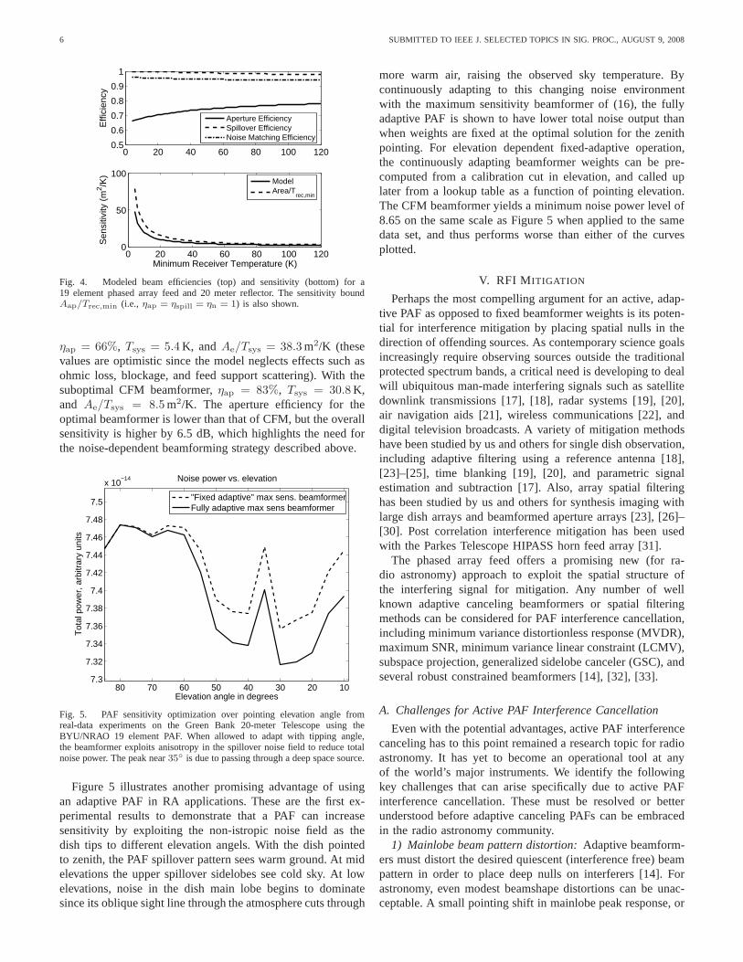
Fig. 4. Modeled beam efficiencies (top) and sensitivity (bottom) for a19 element phased array feed and 20 meter reflector. The sensitivity boundAap/Trec,min (i.e., ηap = ηspill = ηn = 1) is also shown.
ηap = 66%, Tsys = 5.4 K, and Ae/Tsys = 38.3 m2/K (thesevalues are optimistic since the model neglects effects suchasohmic loss, blockage, and feed support scattering). With thesuboptimal CFM beamformer,ηap = 83%, Tsys = 30.8 K,and Ae/Tsys = 8.5 m2/K. The aperture efficiency for theoptimal beamformer is lower than that of CFM, but the overallsensitivity is higher by 6.5 dB, which highlights the need forthe noise-dependent beamforming strategy described above.
10203040506070807.3
7.32
7.34
7.36
7.38
7.4
7.42
7.44
7.46
7.48
7.5
x 10−14
Elevation angle in degrees
Tot
al p
ower
, arb
itrar
y un
its
Noise power vs. elevation
"Fixed adaptive" max sens. beamformerFully adaptive max sens beamformer
Fig. 5. PAF sensitivity optimization over pointing elevation angle fromreal-data experiments on the Green Bank 20-meter Telescopeusing theBYU/NRAO 19 element PAF. When allowed to adapt with tipping angle,the beamformer exploits anisotropy in the spillover noise field to reduce totalnoise power. The peak near35
is due to passing through a deep space source.
Figure 5 illustrates another promising advantage of usingan adaptive PAF in RA applications. These are the first ex-perimental results to demonstrate that a PAF can increasesensitivity by exploiting the non-istropic noise field as thedish tips to different elevation angels. With the dish pointedto zenith, the PAF spillover pattern sees warm ground. At midelevations the upper spillover sidelobes see cold sky. At lowelevations, noise in the dish main lobe begins to dominatesince its oblique sight line through the atmosphere cuts through
more warm air, raising the observed sky temperature. Bycontinuously adapting to this changing noise environmentwith the maximum sensitivity beamformer of (16), the fullyadaptive PAF is shown to have lower total noise output thanwhen weights are fixed at the optimal solution for the zenithpointing. For elevation dependent fixed-adaptive operation,the continuously adapting beamformer weights can be pre-computed from a calibration cut in elevation, and called uplater from a lookup table as a function of pointing elevation.The CFM beamformer yields a minimum noise power level of8.65 on the same scale as Figure 5 when applied to the samedata set, and thus performs worse than either of the curvesplotted.
V. RFI M ITIGATION
Perhaps the most compelling argument for an active, adap-tive PAF as opposed to fixed beamformer weights is its poten-tial for interference mitigation by placing spatial nulls in thedirection of offending sources. As contemporary science goalsincreasingly require observing sources outside the traditionalprotected spectrum bands, a critical need is developing to dealwill ubiquitous man-made interfering signals such as satellitedownlink transmissions [17], [18], radar systems [19], [20],air navigation aids [21], wireless communications [22], anddigital television broadcasts. A variety of mitigation methodshave been studied by us and others for single dish observation,including adaptive filtering using a reference antenna [18],[23]–[25], time blanking [19], [20], and parametric signalestimation and subtraction [17]. Also, array spatial filteringhas been studied by us and others for synthesis imaging withlarge dish arrays and beamformed aperture arrays [23], [26]–[30]. Post correlation interference mitigation has been usedwith the Parkes Telescope HIPASS horn feed array [31].
The phased array feed offers a promising new (for ra-dio astronomy) approach to exploit the spatial structure ofthe interfering signal for mitigation. Any number of wellknown adaptive canceling beamformers or spatial filteringmethods can be considered for PAF interference cancellation,including minimum variance distortionless response (MVDR),maximum SNR, minimum variance linear constraint (LCMV),subspace projection, generalized sidelobe canceler (GSC), andseveral robust constrained beamformers [14], [32], [33].
A. Challenges for Active PAF Interference Cancellation
Even with the potential advantages, active PAF interferencecanceling has to this point remained a research topic for radioastronomy. It has yet to become an operational tool at anyof the world’s major instruments. We identify the followingkey challenges that can arise specifically due to active PAFinterference cancellation. These must be resolved or betterunderstood before adaptive canceling PAFs can be embracedin the radio astronomy community.
1) Mainlobe beam pattern distortion: Adaptive beamform-ers must distort the desired quiescent (interference free)beampattern in order to place deep nulls on interferers [14]. Forastronomy, even modest beamshape distortions can be unac-ceptable. A small pointing shift in mainlobe peak response,or

JEFFS AND WARNICK: ARRAY FEEDS 7
Fig. 6. LCMV beam pattern variation over time (STI index) fora 19 elementPAF on a 20m dish with a strong moving interferer. The patternis for anelevation cut in the far field, combined PAF – dish response, with dish andbeam pointed to zenith. Inset shows mainlobe detail with beams for all STIsplotted on the same axes. Angle is relative to boresight. Theinterferer followeda spiral arc in the sidelobes spanning (10, 80) to (70, 30) in azimuth-elevation.
coma in the beam mainlobe can corrupt sensitive calibratedmeasurements of object brightness spatial distribution.
A potential solution is to use one of several classical con-strained adaptive beamformers [14], [34], [35]. More recentdevelopments in robust beamformers and could improve main-lobe constraint performance in the presence of calibrationerrors [33], [36]. These methods must be studied for suitabilityin the PAF, large reflector, radio astronomy application.
Figure 6 illustrates some aspects of the problem. Theseresults are from a detailed full-wave simulation of a 20m dishand 19 element PAF. INR was 40 dB and the interferer didnot encroach on the mainlobe or near sidelobes. A singlemainlobe constraint at the peak was employed. Note thatthere is significant variation in the mainlobe even thoughinterference stayed in the deep sidelobes. This suggests thatseveral additional constraints would be needed over the 2-Dpattern to maintain shape.
2) Sidelobe pattern rumble: A more subtle undesirableeffect is that variations in the PAF dish illumination sidelobepattern (“pattern rumble”) translate directly to an increase inthe minimum detectable signal level for the radiometer. Figure11 below illustrates the sidelobe rumble effect.
Weak astronomical sources can only be observed by inte-grating the received power for a long period to obtain separatelow variance estimates of signal plus noise power (on source),and noise only (off source). Both signal and noise mustbe stable to an extreme tolerance requirement over the fullintegration time.
The noise field seen by the PAF is dominated by spilloverregion thermal ground radiation, but this is non-isotropicdueto reflector blockage. Because of this anisotropy, even smallvariations in the PAF sidelobe structure in the spillover regioncan significantly perturb beamformer noise levels, causing
intolerable time variation. This occurs even if the beam patternmainlobe is held stable using constrained or robust beam-former techniques. Figure 9 below illustrates the negativeeffect on integrated noise floor estimates when adaptive can-celation perturbs sidelobe patterns.
No known adaptive beamformer can maintain sidelobe de-tailed structure while canceling a moving interferer. Thereare insufficient degrees of freedom to constrain the entiresidelobe pattern. A recent promising method provides bothmainlobe shape and maximum sidelobe level control for in thepresence of strong interference [37]. Though detailed sidelobestructure is not maintained, peak sidelobe levels are kept belowa specified limit. Unfortunately the method requires calibrationinformation for the entire constrained sidelobe region. This isimpractical or impossible for the PAF fed RA telescope dish,except in simulation.
3) Cancellation null depth: The typical astronomical signalpower level is 30 dB or more below the system noise. Cancel-ing nulls must be deep enough to drive interference below theSOI level, i.e. below the on–source minus off–source detectionlimit, not just to the system noise level.
Most algorithms require a dominant interferer to form deepnulls. Minimum variance methods (MVDR, LCMV, max SNRetc.) which balance noise variance with residual interferencepower cannot drive a weaker interferer far below the noisefloor. Zero forcing beamformers like subspace projection candrive deeper nulls, but interference subspace estimation ispoor without a dominant signal, and null depth suffers. Shortintegration times, needed to avoid subspace smearing withmoving interference, increase covariance sample estimationerror which also limits null depth.
We are studying a few approaches to solve this open prob-lem. First, we have shown that use of auxiliary antennassteered to obtain high interference-to-noise ratio (INR) datacan significantly improve cancellation depth when comparedto other array processing algorithms [23]. Second, low orderparametric models can be used to represent moving interfer-ence covariance structure evolution over windows longer thanthe STI stationarity time limit which typically bounds samplecovariance integration. Significant work remains to be doneon this topic.
B. PAF Adaptive Cancellation Methods
We will consider LCMV beamforming and subspace pro-jection beamforming as representative adaptive cancelingal-gorithms. At each STI the well known LCMV weight iscomputed as [14]
wi,j = R−1x,jBi[B
Hi R−1
x,jBi]−1fi (17)
where columns ofBi and response vectorfi define a set oflinear response constraints on thei-th beamformer steered toΩi, such thatBH
i wi,j = fi. These are typically used to controlmainlobe shape, and can be constructed fromaΩi
estimatesprovided by the calibration of Section II-C.
The subspace projection beamformer has time-varyingweight vector given by
wi,j = Pjwi, Pj = I − Ud,jUHd,j (18)

8 SUBMITTED TO IEEE J. SELECTED TOPICS IN SIG. PROC., AUGUST 9,2008
0 0.5 1 1.5 2100
150
200
250CygA_slice_RFI1600_0_mov.bin
Time (min)
Equ
ival
ent A
nten
na T
empe
ratu
re (
Kel
vin)
Fixed Beamformer (RFI Corrupted)Subspace Projection
Fig. 7. Experimental results for the BYU/NRAO L-band 19 element PAFon the Green Bank 20-Meter Telescope, Nov. 2007. RFI mitigation using thesubspace projection beamforming. Interference was a moving CW transmitterin deep reflector sidelobes, while the dish was stepped in elevation throughthe source, 1/4 beamwidth per step.f/D = 0.43.
wherePj is an estimate of the perpendicular projection matrixfor the interference subspace,Vj =
[
v1[jL], · · · ,vQ[jL]]
.Ud,j contains normalized eigenvectors corresponding to theQ largest eigenvalues in the decompositionRx,j = UjΛUH
j
such thatUj = [Ud,j |Us+n,j ].
Fixed beamforming weightwi is designed for the desiredquiescent beam response with mainlobe steered toΩi. Due tothe difficulty in calibrating the PAF response over the entirespillover region, we advocate using the “fixed adaptive” beam-former of (16) usingRn and aΩi
taken from the calibrationprocedure of Section II-C to calculatewi. Alternatively, toprovide additional mainlobe shape constraints inwi, (17) canbe used, replacingRx,j with off-source calibrationRn.
Figure 7 presents new observations obtained during ourrecent PAF experiments on the NRAO Green Bank 20-MeterTelescope. The improvement in signal of interest responseusing subspace projection beamforming to reject an interfereris quite significant.
C. Correcting Pattern Rumble Bias
We have recently introduced an algorithm [38], [39] whichadapts the corrected spatial filtering approach of Leshem andvan der Veen [40] to the problem of power spectral density(PSD) estimation with a sensor array. When conventionalPSD algorithms are applied to the output of an adaptivebeamformer, as in Figure 2, a significant bias error appearsin the spectrum due to beampattern variation (pattern rumble)while tracking a moving interference. The new bias correctedsubspace projection beamformer removes this error.
Instead of the cascaded beamformer and PSD estimator asseen in Figure 2, we proposed a joint adaptive canceler and
−1 −0.5 0 0.5 1−10
−5
0
5
10
ω, radian frequency × π
Rel
ativ
e P
ower
(dB
/rad
/sam
ple)
Power Spectral Density Estimates
Bias corrected subspaceConventionalSubspace ProjectionLCMV
0.4 0.6 0.8 1
−9.9
−9.8
−9.7
Fig. 8. Simulated pattern rumble bias correction results at1600 MHz for a19 element PAF on a 20m diameter dish withf/D = 0.33. The interfereris the dominant FM modulated tone seen centered atω = −0.37π in theconventional fixed beamformer PSD response. Inset shows expanded noisefloor detail. PSD levels are normalized for equal response tothe SOI. Thedish and beam are pointed to zenith. The interferer followeda spiral arc inthe sidelobes spanning (10, 80) to (70, 30) in azimuth-elevation during4700 STI periods ofL = 1024 samples each.
estimator as follows
STyi
=α
M(wH
i ⊗ wTi )C−1
M−1∑
j=0
[
(Pj(FFTNXj ⊙ Γ))
(Pj(FFTNXj ⊙ Γ))∗]
, (19)
C =1
M
M−1∑
j=0
(Pj ⊗ P∗
j )
whereFFTN · denotes theN point one-dimensional fastFourier transform along matrix rows,M is the number of FFTwindows which are averaged, andwi and Pj are defined in(18). Each row ofΓ is a copy of the tapered window (e.g.Hamming) used to reduce spectral leakage, andα is a scalefactor to correct bulk scale bias introduced byΓ.
It was shown that for a small uniform line array (19)produces an “effective beam pattern,” on average over thefull integration interval, which exactly matches the quiescentbeamformer that non-adaptivewi alone would produce [39].Pattern-rumble-induced PSD bias is also removed. These cor-rections are accomplished while canceling the interferer.Noother known adaptive array processor is capable of this.
Figures 8 – 11 present new results of a detailed numericalsimulation for the electromagnetic response of a 19 elementPAF on a 20m dish with a strong moving interferer seen deepin the dish sidelobes. The algorithm succeeds in maintaininga perfect effective beamshape for both the far dish patternon the sky, and the PAF illumination pattern on the dish. Anf/D = 0.33 was chosen for the simulation since it results insomewhat more pattern rumble than thef/D = 0.43 of theGreen Bank 20-Meter Telescope.
These results are the first to demonstrate that bias correctionis effective in a PAF and large reflector environment, including

JEFFS AND WARNICK: ARRAY FEEDS 9
100
102
10−6
10−4
10−2
Integration Time (sec)
Noi
se P
ower
Bia
s (K
)
SP (Uncorrected)SP (Bias corrected)
t−1/2
Fig. 9. Difference (error) between cumulative integrated beamformer noisepower estimate and true noise power for a 19 element PAF modelwith 20meter reflector,f/D = 0.33. With bias correction, increased integration timeyields a noise power estimate which converges at the theoretical rate to theexpected noise power (thet−1/2 sample error stdv. curve). Without biascorrection additional integration time fails to reduce error variance.
non-identical, complex element response patterns, reflectorbeam focusing effects, strong mutual coupling, and correlatedreceiver and spillover noise. Previously, bias correctionwasonly known to fully correct the effective beampattern for auniform line array. The electromagnetic simulation used finiteelement modeling for the PAF, microwave network theory forreceiver noise, and physical optics for the reflector.
Pattern rumble in the spillover region has biased the noisefloor PSD estimate high, even with long integration, for bothsubspace projection and LCMV cancelers. The bias correctedalgorithm solves the problem, bringing the noise floor down tothe level that would be seen by the conventional fixed weightbeamformer in the absence of interference.
For this experiment the total in-band power INR was +40dB. The SOI is a multiband filtered Gaussian random pro-cess, seen as a step pattern between−0.5π ≤ ω ≤ 0.25π.SNR was -5 dB, which though higher than a typical deepspace source, provides a clearly readable illustration. Theconventional beamformer PSD is completely dominated by theinterferer, and would fail at estimating SOI spectrum insidethe interference band. LCMV and subspace projection botheffectively cancel interference, but raise the noise floor asseen in the inset. The bias corrected PSD completely cancelsinterference but has the same noise floor level as the non-adaptive conventional beamformer, outside of the interferencespectrum.
The demonstrated level of noise floor bias due to uncor-rected interference cancelation seems small, but would becatastrophic when trying to detect mJy andµJy level spacesources. This is particularly true since with a moving andperhaps intermittent interferer, the bias levels in on-source andoff-source PSDs would be different.
Figure 9 shows the importance of bias correction for longintegration detection. The simulation scenario matches Figure8, but with no SOI. Total noise power sample estimates inbeamformer output,yi[n], are shown for subspace projectionwith a strong interferer present. With increasing integrationtime the uncorrected subspace projection fails to convergedue to pattern rumble bias. On the other hand, bias corrected
0 5
0
10
Angle in degrees
Subspace Projection Pattern Rumble
dB R
elat
ive
to P
eak
Fig. 10. Main beam (dish and PAF) pattern rumble with subspace projectionalgorithm over many STI windows for 19 element PAF model with20 meterreflector,f/D = 0.33. The bias corrected effective response pattern is shownwith the solid black line. It exactly matches the quiescent,fixed weightconventional beamformer.
0 50 100
0
Angle in degrees
Subspace Projection Illumination Pattern Rumble
dB R
elat
ive
to P
eak
Fig. 11. Illumination pattern on the dish for the bare PAF array with subspaceprojection algorithm over many STI windows for 19 element PAF model with20 meter reflector,f/D = 0.33. Vertical lines denote the dish rim. The biascorrected effective response pattern is shown with the solid black line. Itexactly matches the quiescent, fixed weight conventional beamformer.
subspace projection converges at the theoreticalt−1/2 ratetoward the true power. For the example source described inSection III, the signal of interest would not be detectable untilthe integrated noise power estimate bias is below 3.4 mK.
Figures 10 and 11 show another significant aspect of biascorrection. Simulated elevation cuts through the main beam(combined dish and PAF) and dish illumination pattern of thebare PAF array are shown. The same moving interferer sce-nario as in Figure 8 is used with the 19 element PAF and 20mdish. Patterns for each STI are over-plotted on the same axesto illustrate the range of variation over time. The solid blackcurve represents the effective bias corrected beampatternoverthe full integration window. It exactly matches the quiescentbeampattern formed using fixed weights,wi.
The effective bias corrected pattern is computed by storing
10 SUBMITTED TO IEEE J. SELECTED TOPICS IN SIG. PROC., AUGUST 9,2008
projection matrices,Pj , formed during a run with the signalplus noise plus interference data. A new probing data set,XΩk,j , 0 ≤ j < M , is generated with a single far-field pointsource at angleΩk, and no noise or interference. Effectiveresponse in directionΩi is computed using the previouslysavedPj with probe signalXΩk,j in (19). The process isrepeated for each plotted arrival angle.
The wide variation in main beam (dish and PAF) patternover the STIs is entirely unacceptable for the precise radio-metric observations needed for credible astronomical science.This is why astronomers have not embraced adaptive arrayprocessing to deal with their interference mitigation problems.The bias corrected effective beam response resolves theseconcerns for PSD observations.
An interesting aspect of Figure 11 is the “hole” in the centerof the pattern. The quiescent beamformer fixed weights werecomputed using (16) with calibration data. Apparently it ismore important in the optimization to form sharper transitionsto low sidelobe response at the dish edge than to enforce asmooth pattern across the dish. The hole covers only a smallcentral area of the dish under the obscuring feed array. Thesensitivity achieved with this solution is higher than any otherillumination pattern possible for the 19 element PAF, includ-ing smooth response, hole-free patterns. For larger arrays, acharacteristic FIR filter passband ripple pattern appears.
VI. CONCLUSIONS
Signal processing for radio telescopic phased array feedsoffers a rich and challenging regime for algorithm develop-ment. Due to the extremely tight system tolerances and lownoise requirements for astronomical observations, an accuratesignal and noise model is required in order to assess the keyfactors that affect beamformer performance. This is especiallytrue in regard to correlated spillover and receiver noise. Inorder to characterize the performance of a given beamformer,we have extended the standard definitions of antenna figures ofmerit, such as aperture efficiency, to an array feed. Even fornon-adaptive beamforming, statistically optimal beamformersolutions will likely be required each time the array is re-calibrated.
Of particular importance is the gain and pattern stabilityrequired for radiometric detection of weak signals. In the pres-ence of interferers, adaptive algorithms which have adequateperformance for communications applications are unusablefor radio astronomy. The well known adaptive cancelers canlead to a system power bias which is small in absoluteterms, but for astronomical observations would completelyobscure weak signals of interest in many cases. We presentedmodeled results for a bias correction algorithm which removesthe bias caused by pattern rumble associated with adaptivecancellation. Our initial experimental results are promising,but resolving the remaining open technical questions willrequire cooperative research in several disciplines, includingsensor array processing, real-time signal processing systems,electromagnetics, antenna design, and astronomy.
APPENDIX
The following notation, operators and identities are used:
1) EA : Expected value of randomA.2) Em(Ω): Far-field electric field pattern at spherical angle
Ω due to array element m.3) ⌊a⌋ : Floor operation, rounding toward zero.4) a∗ : complex conjugate ofa.5) AT , AH : transpose and conjugate transpose ofA.6) A : estimate ofA.7) A⊗ B : Kronecker matrix product.8) A B = [a1 ⊗b1, · · · ,aN ⊗bN ], Khatri–Rao product.9) A⊙ B : element-wise, or Hadamard array product.
REFERENCES
[1] John D. Kraus,Radio Astronomy, Second Ed., Cygnus-Quasar Books,Powell, Ohio, 1986.
[2] S. Snezana and NAIC-NRAO Summer School on Single Dish Radio As-tronomy, Single-dish radio astronomy : techniques and applications :proceedings of the NAIC-NRAO Summer School, Astronomical Societyof the Pacific, San Francisco, 2002.
[3] A.R. Thompson, J.M. Moran, and G.W. Swenson Jr.,Interferometry andSynthesis in Radio Astronomy, Second Edition, Wiley-Interscience, NewYork, 2001.
[4] L. Staveley-Smith et al, “The Parkes 21-cm multibeam receiver,”Publications of the Astronomical Society of Australia, PASA, vol. 13,pp. 243 –, 1996, see also http://www.atnf.csiro.au/research/multibeam/.
[5] J.R. Fisher and R.F. Bradley, “Full sampling array feedsfor radiotelescopes,”Proceedings of the SPIE, Radio Telescopes, vol. 4015, pp.308–318, 2000.
[6] Chad K. Hansen, Karl F. Warnick, Brian D. Jeffs, J. Richard Fisher, andRichard Bradley, “Interference mitigation using a focal plane array,”Radio Science, vol. 40, doi:10.1029/2004RS003138, no. 5, June 2005.
[7] Bruce Veidt and Peter Dewdney, “A phased-array feed demonstrator forradio telescopes,” inProc. URSI General Assembly, 2005.
[8] R. Maaskant, M. V. Ivashina, R. Mittra, and N. T. Huang, “ParallelFDTD modeling of a focal plane array with Vivaldi elements onthehighly parallel LOFAR BlueGene/L supercomputer,” inProc. IEEEAntennas and Propagation Symposium, Albuquerque, NM, June 20-252006, pp. 3861 – 3864.
[9] International SKA Steering Committee (ISSC),SKA project home page,2008, http://www.skatelescope.org/.
[10] J.R. Nagel, K.F. Warnick, B.D. Jeffs, J.R. Fisher, and R. Bradley,“Experimental verification of radio frequency interference mitigationwith a focal plane array feed,”Radio Science, vol. 42, 2007, RS6013,doi:10.1029/2007RS003630.
[11] K. F. Warnick and B. D. Jeffs, “Beam efficiencies and system tempera-ture for a focal plane array,” Tech. Rep. http://hdl.handle.net/1877/588,Brigham Young University, Provo, UT, Nov. 2007.
[12] K. F. Warnick and M. A. Jensen, “Optimal noise matching for mutually-coupled arrays,”IEEE Transactions on Antennas and Propagation, vol.55, no. 6, pp. 1726–1731, June 2007.
[13] K. F. Warnick and M. A. Jensen, “Effect of mutual coupling oninterference mitigation with a focal plane array,”IEEE Trans. Ant.Propag., vol. 53, no. 8, pp. 2490–2498, Aug. 2005.
[14] H.L. Van Trees,Detection, Estimation, and Modulation Theory, Part IV,Optimum Array Processing, John Wiley and Sons, 2002.
[15] K. F. Warnick and B. D. Jeffs, “Gain and aperture efficiency for areflector antenna with an array feed,”IEEE Antennas and WirelessPropagation Letters, vol. 5, no. 1, pp. 499–502, 2006.
[16] M. Ivashina and C.G.M van‘t Klooster, “Focal fields in reflectorantennas and associated array feed synthesis for high efficiency multi-beam performances,” inProceedings of the ESTEC Antenna Workshop,Noordwijk, The Netherlands, Sept. 2002.
[17] J.F. Bell S.W. Ellingson, J. Bunton, “Removal of the GLONASS C/Asignal from OH spectral line observations using a parametric modelingtechnique,”Astrophysical J. Supplement, vol. 135, pp. 87–93, July 2001.
[18] A.J. Poulsen, B.D. Jeffs, K.F. Warnick, and J.R. Fisher, “Programmablereal-time cancellation of GLONASS interference with the Green Banktelescope,”Astronomical Journal, vol. 130, no. 6, pp. 2916 – 2927, Dec.2005.
[19] B.D. Jeffs, W. Lazarte, and J.R. Fisher, “Bayesian detection ofradar interference in radio astronomy,”Radio Science, vol. 41, pp.doi:10.1029/2005RS003400, June 2006.

JEFFS AND WARNICK: ARRAY FEEDS 11
[20] S.W. Ellingson and G.A. Hampson, “Mitigation of radar interfernece inL-band radio astronomy,”The Astrophysical Journal Suplement Series,vol. 147, pp. 167–176, 2003.
[21] Q. Zhang, Y. Zheng, S.G. Wilson, J.R. Fisher, and R. Bradley, “Excisionof distance measuring equipment interference from radio astronomysignals,” The Astronomical Journal, vol. 129, no. 6, pp. 2933–2939,June 2005.
[22] A.J. Boonstra, A. Leshem, A-J van der Veen, A. Kokkeler,andG. Schoonderbeek, “The effect of blanking of TDMA interference onradio-astronomical observations: experimental results,” in Proc. of theIEEE International Conf. on Acoust., Speech, and Signal Processing,2000, vol. 6, pp. 3546–3549.
[23] B.D. Jeffs, L. Li, and K.F. Wanick, “Auxiliary antenna assistedinterference mitigation for radio astronomy arrays,”IEEE Trans. SignalProcessing, vol. 53, no. 2, pp. 439–451, Feb. 2005.
[24] C. Barnbaum and R.F. Bradley, “A new approach to interference excisionin radio astronomy: Real-time adaptive cancellation,”AstronomicalJournal, vol. 116, pp. 2598–2614, Nov. 1998.
[25] F.H. Briggs, J.F. Bell, and J. Kesteven, “Removing radio interferencefrom contaminated astronomical spectra using an independent referencesignal and closure relations,”Astronomical Journal, vol. 120, pp. 3351–3361, Aug. 2000.
[26] S. van der Tol and A.-J. van der Veen, “Performance analysis of spatialfiltering of rf interference in radio astronomy,”IEEE Trans. SignalProcessing, vol. 53, no. 3, Mar. 2005.
[27] A. Leshem and A.-J. van der Veen, “Radio-astronomical imaging in thepresence of strong radio interference,”IEEE Trans. Inform. Theory, vol.46, no. 5, pp. 1730–1747, Aug. 2000.
[28] A.J. Boonstra, S.J. Wijnholds, S. v.d. Tol, and B. Jeffs, “Calibration,sensitivity, and rfi mitigation requirements for lofar,” inProc. of theIEEE International Conf. on Acoust., Speech, and Signal Processing,Mar. 2005, vol. V, pp. 869–872.
[29] S.W. Ellingson, “Beamforming and interference canceling with verylarge wideband arrays,”IEEE Trans. Antennas Propagat., vol. 51, no.6, pp. 1338–1346, June 2003.
[30] G.C. Bower, “Radio frequency interference mitigationfor detection ofextended sources with an interferometer,”Radio Science, vol. 40, no.RS5S07, Dec. 2005, doi:10.1029/2004RS003141.
[31] D.G. Barnes, F.H. Briggs, and M.R. Calabretta, “Postcorrelationripple removal and radio frequency interference rejectionfor parkestelescope survey data,”Radio Science, vol. 40, no. RS5S13, Dec. 2005,doi:10.1029/2004RS003139.
[32] S.W. Ellingson and G.A. Hampson, “A subspace-trackingapproachto interference nulling for phased array-based radio telescopes,” IEEETrans. Antennas Propagat., vol. 50, no. 1, pp. 25–30, Jan. 2002.
[33] Jian Li and Petre Stoica, Eds.,Robust Adaptive Beamforming, Wiley-Intersicience, Hoboken, New Jersey, 2005.
[34] S.P. Applebaum and D.J. Chapman, “Adaptive arrays withmain beamconstraints,”IEEE Trans. Antennas Propagat., vol. AP-24, pp. 650–662,Sept. 1976.
[35] C-Y. Tseng and L.J. Griffiths, “A unified approach to the design oflinear constraints in minimum variance adaptive beamformers,” IEEETrans. on Antennas and Propagation, vol. AP-40, pp. 1533 –1542, Dec.1992.
[36] A.B. Gershman, U. Nickel, and J.F. Bohme, “Adaptive beamformingalgorithms with robustness against jammer motion,”IEEE Trans. onSignal Proc., vol. 45, no. 3, pp. 1878–1885, July 1997.
[37] J. Li, Y. Xie, P. Stoica, X. Zheng, and J. Ward, “Beampattern synthesisvia a matrix approach for signal power estimation,”IEEE Trans. SignalProcessing, vol. 55, no. 12, pp. 5643–5657, Dec. 2007.
[38] B.D. Jeffs and K.F. Warnick, “Bias corrected psd estimation with aninterference canceling array,” inProc. of the IEEE International Conf.on Acoust., Speech, and Signal Processing, Honolulu, Apr. 2007, vol. II,pp. 1145–1148.
[39] B.D. Jeffs and K.F. Warnick, “Bias corrected psd estimation foran adaptive array with moving interference,”IEEE Trans. SignalProcessing, vol. 56, no. 7, pp. 3108–3121, July 2008.
[40] A. Leshem, A.-J. van der Veen, and A.-J. Boonstra, “Multichannelinterference mitigation techniques in radio astronomy,”AstrophysicalJournal Supplements, vol. 131, no. 1, pp. 355–374, 2000.
Brian D. Jeffs (M’90–SM’02) received B.S. (magnacum laude) and M.S. degrees in electrical engineer-ing from Brigham Young University in 1978 and1982 respectively. He received the Ph.D. degree fromthe University of Southern California in 1989. He iscurrently an associate professor in the Departmentof Electrical and Computer Engineering at BrighamYoung University, where he lectures in the areas ofdigital signal processing, digital image processing,and probability theory. Current research interestsinclude array signal processing for radio astronomy,
RF interference mitigation, MIMO wireless communications, and digitalimage restoration. Previous employment includes Hughes Aircraft Companywhere he served as a sonar signal processing systems engineer in the anti-submarine warfare group. Dr. Jeffs was a Vice General Chair for IEEEICASSP-2001, held in Salt Lake City Utah. He was a member of the executiveorganizing committee for the 1998 IEEE DSP Workshop, and served severalyears as chair of the Utah Chapter of the IEEE Communicationsand SignalProcessing Societies.
Karl F. Warnick (S’95–M’98–SM’04) receivedthe B.S. degree (magna cum laude) with Univer-sity Honors and the Ph.D. degree from BrighamYoung University in 1994 and 1997, respectively.From 1998 to 2000, he was a Postdoctoral Re-search Associate in the Center for ComputationalElectromagnetics at the University of Illinois atUrbana-Champaign. Since 2000, he has been afaculty member in the Department of Electrical andComputer Engineering at Brigham Young, where heis currently an Associate Professor. He has authored
a book, Problem Solving in Electromagnetics, Microwave Circuits, andAntenna Design for Communications Engineering (Artech House). Researchinterests include array antenna systems, computational electromagnetics,remote sensing, and inverse scattering. Dr. Warnick was a recipient of theNSF Graduate Research Fellowship, Outstanding Faculty Member award forElectrical and Computer Engineering in 2005, and the BYU Young ScholarAward (2007), and served as Technical Program Co-Chair for the 2007 IEEEInternational Symposium on Antennas and Propagation.
Jonthan Landon, Jacob Waldron, and David Joneseach received the B.S.degree from Brigham Young University in 2006. Mr. Landon is currentlypursuing the Ph.D. degree, while Mr. Waldron and Mr. Jones completed theirM.S. degrees in August, 2008, all in the Department of Electrical and Com-puter Engineering at BYU. Mr. Landon has interests in array signal processingtheory and systems, and was lead graduate engineer of platform developmentfor the Green Bank 20-Meter Telescope experiment reported in this paper.Mr. Waldron’s interests include microwave antennas and circuits, and heconstructed the 19 element experimental array. Mr. Jones’ interests includecomputational electromagnetics, and he developed numerical simulation codefor array and dish modeling.
J. Richard Fisher (M’74) received the B.S. degree in physics from Penn-sylvania State University in 1965, and the Ph.D. degree in astronomy fromUniversity of Maryland in 1972. He has been with the NationalRadioAstronomy Observatory since 1972, where he current serves as TechnicalResearch and Development Leader at the NRAO Charlottesville, VA campus.He has been a visiting researcher at radio astronomy laboratories in Australiaand India. His research interests include RFI mitigation, single dish phasedarray feeds, and instrument development for radio astronomy.
Roger D. Norrod (M) received the B.S. and M.S. degrees in ElectricalEngineering from Tennessee Technological University in 1973 and 1979respectively. Since 1979 he has been an electronics engineer at the NationalRadio Astronomy Observatory, Green Bank WV. His activitiesthere haveincluded cryogenic LNA design, VLBA receiver design, head of 100-MeterGreen Bank Telescope Antenna Optics group, and manager of NRAO systemsdevelopment for the GBT. He has previously worked at Texas Instruments,Inc., and Scientific Communications, Inc. as a radar applications and RFinstrumentation engineer.