signaling lights
TRANSCRIPT
Switc
hes
& P
ilot L
ight
sSi
gnal
ing
Ligh
tsRe
lays
& S
ocke
tsTi
mer
sCo
ntac
tors
Term
inal
Blo
cks
Circ
uit B
reak
ers
LD6A Signaling Lights
704 www.IDEC.com
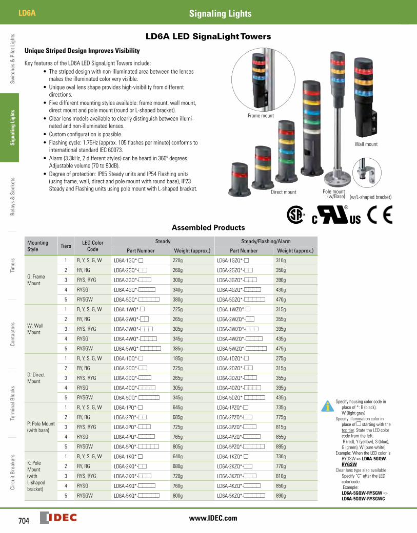
LD6A LED SignaLight Towers
Unique Striped Design Improves Visibility
Key features of the LD6A LED SignaLight Towers include:• The striped design with non-illuminated area between the lenses
makes the illuminated color very visible.• Unique oval lens shape provides high-visibility from different
directions.• Five different mounting styles available: frame mount, wall mount,
direct mount and pole mount (round or L-shaped bracket).• Clear lens models available to clearly distinguish between illumi-
nated and non-illuminated lenses.• Custom configuration is possible.• Flashing cycle: 1.75Hz (approx. 105 flashes per minute) conforms to
international standard IEC 60073. • Alarm (3.3kHz, 2 different styles) can be heard in 360º degrees.
Adjustable volume (70 to 90dB).• Degree of protection: IP65 Steady units and IP54 Flashing units
(using frame, wall, direct and pole mount with round base), IP23 Steady and Flashing units using pole mount with L-shaped bracket.
(w/L-shaped bracket)
Frame mount
Direct mount Pole mount(w/Base)
Wall mount
Assembled Products
Mounting Style Tiers LED Color
CodeSteady Steady/Flashing/Alarm
Specify housing color code in place of *: B (black), W (light gray)
Specify illumination color in place of starting with the top tier. State the LED color code from the left. R (red), Y (yellow), S (blue), G (green), W (pure white)
Example: When the LED color is RYGSW => LD6A-5GQW-RYGSW
Clear lens type also available. Specify “C” after the LED color code. Example: LD6A-5GQW-RYSGW => LD6A-5GQW-RYSGWC
Part Number Weight (approx.) Part Number Weight (approx.)
G: Frame Mount
1 R, Y, S, G, W LD6A-1GQ*- 220g LD6A-1GZQ*- 310g
2 RY, RG LD6A-2GQ*- 260g LD6A-2GZQ*- 350g
3 RYS, RYG LD6A-3GQ*- 300g LD6A-3GZQ*- 390g
4 RYSG LD6A-4GQ*- 340g LD6A-4GZQ*- 430g
5 RYSGW LD6A-5GQ*- 380g LD6A-5GZQ*- 470g
W: Wall Mount
1 R, Y, S, G, W LD6A-1WQ*- 225g LD6A-1WZQ*- 315g
2 RY, RG LD6A-2WQ*- 265g LD6A-2WZQ*- 355g
3 RYS, RYG LD6A-3WQ*- 305g LD6A-3WZQ*- 395g
4 RYSG LD6A-4WQ*- 345g LD6A-4WZQ*- 435g
5 RYSGW LD6A-5WQ*- 385g LD6A-5WZQ*- 475g
D: Direct Mount
1 R, Y, S, G, W LD6A-1DQ*- 185g LD6A-1DZQ*- 275g
2 RY, RG LD6A-2DQ*- 225g LD6A-2DZQ*- 315g
3 RYS, RYG LD6A-3DQ*- 265g LD6A-3DZQ*- 355g
4 RYSG LD6A-4DQ*- 305g LD6A-4DZQ*- 395g
5 RYSGW LD6A-5DQ*- 345g LD6A-5DZQ*- 435g
P: Pole Mount(with base)
1 R, Y, S, G, W LD6A-1PQ*- 645g LD6A-1PZQ*- 735g
2 RY, RG LD6A-2PQ*- 685g LD6A-2PZQ*- 775g
3 RYS, RYG LD6A-3PQ*- 725g LD6A-3PZQ*- 815g
4 RYSG LD6A-4PQ*- 765g LD6A-4PZQ*- 855g
5 RYSGW LD6A-5PQ*- 805g LD6A-5PZQ*- 895g
K: Pole Mount (with L-shaped bracket)
1 R, Y, S, G, W LD6A-1KQ*- 640g LD6A-1KZQ*- 730g
2 RY, RG LD6A-2KQ*- 680g LD6A-2KZQ*- 770g
3 RYS, RYG LD6A-3KQ*- 720g LD6A-3KZQ*- 810g
4 RYSG LD6A-4KQ*- 760g LD6A-4KZQ*- 850g
5 RYSGW LD6A-5KQ*- 800g LD6A-5KZQ*- 890g
Switches &
Pilot LightsSignaling Lights
Relays & Sockets
Timers
ContactorsTerm
inal BlocksCircuit Breakers
705800-262-IDEC (4332) • USA & Canada
LD6ASignaling Lights
Combination of LED Color and Lens ColorLED Color Color Lens Type Clear Lens Type
R: Red Red lens Clear lens
Y: Yellow Yellow lens Clear lens
S: Blue Blue lens Clear lens
G: Green Green lens Clear lens
W: White Clear lens
For white (W) LED, a clear lens is used in both color and clear lens configurations.
Mounting Parts IncludedMounting Style Supplied Parts
G: Frame mount M4 screw (4 pcs)*, M4 spring washer (4 pcs)*, M4 plain washer (4 pcs)*, M5 screw (2 pcs), M5 spring washer (2 pcs), M5 plain washer (2 pcs), bracket (1 pc)
W: Wall mount M4 screw (20 mm) (4 pcs), M4 screw (8 mm) (4 pcs)*, M4 spring washer (8 pcs)* M4 plain washer (8 pcs)*, M4 nut (4 pcs), bracket (1 pc), gasket (1 pc)
D: Direct mount M5 screw (4 pcs)*, M5 spring washer (4 pcs)*, M5 plain washer (4 pcs)*, M5 nut (4 pcs)*, O-ring (4 pcs), gasket (1 pc)
P: Pole mount (with base)
M5 screw (4 pcs), M5 spring washer (4 pcs), M5 plain washer (4 pcs), M5 nut (4 pcs), O-ring (4 pcs), gasket (1 pc)
K: Pole mount (with L-shaped bracket) M22 plain washer 2 (pcs), M22 nut (2 pcs), bracket (1 pc)
*For black housing, black screws and washers are supplied. For light gray housing, silver screws and washers are supplied.
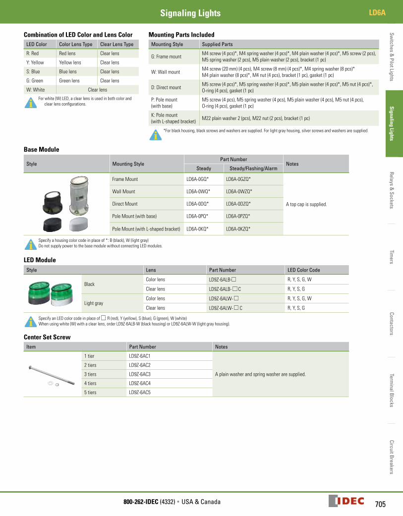
Base Module
Style Mounting StylePart Number
NotesSteady Steady/Flashing/Alarm
Frame Mount LD6A-0GQ* LD6A-0GZQ*
A top cap is supplied.
Wall Mount LD6A-0WQ* LD6A-0WZQ*
Direct Mount LD6A-0DQ* LD6A-0DZQ*
Pole Mount (with base) LD6A-0PQ* LD6A-0PZQ*
Pole Mount (with L-shaped bracket) LD6A-0KQ* LD6A-0KZQ*
Specify a housing color code in place of *: B (black), W (light gray)Do not supply power to the base module without connecting LED modules.
LED ModuleStyle Lens Part Number LED Color Code
BlackColor lens LD9Z-6ALB- R, Y, S, G, W
Clear lens LD9Z-6ALB- C R, Y, S, G
Light grayColor lens LD9Z-6ALW- R, Y, S, G, W
Clear lens LD9Z-6ALW- C R, Y, S, G
Specify an LED color code in place of : R (red), Y (yellow), S (blue), G (green), W (white)When using white (W) with a clear lens, order LD9Z-6ALB-W (black housing) or LD9Z-6ALW-W (light gray housing).
Center Set ScrewItem Part Number Notes
1 tier LD9Z-6AC1
A plain washer and spring washer are supplied.
2 tiers LD9Z-6AC2
3 tiers LD9Z-6AC3
4 tiers LD9Z-6AC4
5 tiers LD9Z-6AC5

Switc
hes
& P
ilot L
ight
sSi
gnal
ing
Ligh
tsRe
lays
& S
ocke
tsTi
mer
sCo
ntac
tors
Term
inal
Blo
cks
Circ
uit B
reak
ers
LD6A Signaling Lights
706 www.IDEC.com
Ordering Examples[Ex. 1] When ordering LD6A-3PQW-RYG as sub-component parts, specify the following: Pole mount (with base), steady, light gray housing, 3 tiers, color lens LED modules with Red, Yellow, and Green LED Base module (pole mount with base, steady, light gray housing) LD6A-0PQW 1 piece LED module (red LED with color lens, light gray housing) LD9Z-6ALW-R 1 piece LED module (yellow LED with color lens, light gray housing) LD9Z-6ALW-Y 1 piece LED module (green LED with color lens, light gray housing) LD9Z-6ALW-G 1 piece Center screw set (3 tiers) LD9Z-6AC3 1 piece
[Ex. 2] When ordering LD6A-5WZQB-RYSGWC as sub-component parts, specify the following: Wall mount, steady/flashing/alarm, black housing, 5 tiers, clear lens LED modules with Red, Yellow, Blue, Green, and Pure white LED Base module (wall mount, steady/flashing/alarm, black housing) LD6A-0WZQB 1 piece LED module (red LED with clear lens, black housing) LD9Z-6ALB-RC 1 piece LED module (yellow LED with clear lens, black housing) LD9Z-6ALB-YC 1 piece LED module (blue LED with clear lens, black housing) LD9Z-6ALB-SC 1 piece LED module (green LED with clear lens, black housing) LD9Z-6ALB-GC 1 piece LED module (pure white LED with clear lens, black housing) LD9Z-6ALB-W 1 piece Center screw set (5 tiers) LD9Z-6AC5 1 piece
Replacement PartsItem Description Part Number Notes
Top Cap
Black LD9Z-6ATB
A top cap is supplied with a base module.
Light gray LD9Z-6ATW
L-shaped Bracket Metal(chrome-plated) LD9Z-6AK Two plain washers and two nuts are supplied.

Switches &
Pilot LightsSignaling Lights
Relays & Sockets
Timers
ContactorsTerm
inal BlocksCircuit Breakers
707800-262-IDEC (4332) • USA & Canada
LD6ASignaling Lights
SpecificationsSpecifications
Safety Standards IEC60947-5-1, EN60947-5-1, UL508,CSA C22.2 No.14
Operating Temperature –25 to +55ºC (no freezing)
Operating Humidity 45 to 85% RH (no condensation)
Storage Temperature –40 to +75ºC (no freezing)
Overvoltage Category III (IEC60664-1)
Impulse Withstand Voltage 800V (IEC60947-1)
Insulation Resistance 100 MΩ minimum (500V DC megger)
Dielectric Strength Between live and dead parts: 1000V AC, 1 minute
Pollution Degree 3
Corrosion Immunity Atmosphere free from corrosive gases
Vibration Resistance Operating extremes: 10 to 55Hz, amplitude 0.5 mm
Shock Resistance Operating extremes: 147 m/s2, 6 shocks each in 6 axes
Degree of Protection(IEC60529)
Steady frame mount, wall mount, direct mount, pole mount with base IP65
Steady pole mount with L-shaped bracket IP23
Flashing/Alarm
frame mount, wall mount, direct mount, pole mount with base IP54
Flashing/Alarm pole mount with L-shaped bracket IP23
Housing Color Black, Light gray
Material
Housing: ABS resinLens: AS resinPole: Steel (nickel-chrome plated)Pole base: Diecast aluminum
Wire 22AWG
Functional SpecificationsRated Insulation Voltage 60V
Operating Voltage 24V AC/DC ±10%
Rated Voltage (Ue) 24V AC/DC
LED Color Code R (red), Y (yellow), S (blue), G (green), W (white)
LED
Illumination Color R, Y S, G W
Rated Current (per tier) 25mA 30mA 20mA
Power Consumption (per tier) 0.6W 0.75W 0.5W
LED Life (Note)Approx. 30,000 hours (until brightness is reduced to 50% of the initial value in a 25ºC operating environment)
Flashing Cycle (IEC60073) Approx. 105 flashes per minute (1.75 Hz)
Alar
m
Alarm Cycle Alarm 1: approx. 700 times per minuteAlarm 2: approx. 35 times per minute
Current Draw 110mA max.
Inrush Current AC: 400mA max. DC: 250mA max.
Alarm Volume 70 to 90dB, at 1m (volume adjustable)
Acoustic Frequency Approx. 3.3kHz
Note: Life of the LED varies according to operating conditions and environment.
External Contact Ratings
LED
AC Contact Capacity(per tier)
Current Capacity 100mA min.
Dielectric Strength 35V AC min.
DC Contact Capacity, Transistor Capacity (per tier)
Current Capacity 100mA min.
Dielectric Strength 35V min.
Leakage Current 0.1mA max.
Alar
m
AC Contact Capacity(per alarm)
Current Capacity 400mA min.
Dielectric Strength 35V AC min.
DC Contact Capacity, Transistor Capacity (per alarm)
Current Capacity 300mA min.
Dielectric Strength 35V min.
Leakage Current 0.1mA max.

Switc
hes
& P
ilot L
ight
sSi
gnal
ing
Ligh
tsRe
lays
& S
ocke
tsTi
mer
sCo
ntac
tors
Term
inal
Blo
cks
Circ
uit B
reak
ers
LD6A Signaling Lights
708 www.IDEC.com
Dimensions (Steady Light)Frame Mount Wall Mount Direct Mount Pole Mount (with base) Pole Mount (with L-shaped bracket)
40
6052
.440
4060
53.4
40
60
40
ø70
60
40 ø94
60
40
2517
.412
.6
2517
.412
.6
2517
.412
.6
2517
.412
.6
2517
.412
.6
L198
0
L2
L310
40
L473
0
L580
730
32
6565
980
6080
40
Conduit PortM20×P1.5
Front Front Front
Dimension Table
Tiers Frame Mount (L1)
Wall Mount (L2)
Direct Mount(L3)
Pole Mount
w/ base (L4) w/ L-shaped bracket (L5)
1 156 156 98 408 372
2 186 186 128 438 402
3 216 216 158 468 432
4 246 246 188 498 462
5 276 276 218 528 492
Panel Cut-Out
Frame Mount Wall Mount Direct Mount* Pole Mount (with base)Pole Mount
(with L-shaped bracket)
ø22
2-ø11
35
44.0
2-M5
4-ø4.5
46
23
16
Wire Entryø15
+10
ø54
4-ø5.5
90°
Wire Entryø15
Front
4-ø5.5
ø73
4-ø4.5
ø73
90°
Pattern A* Pattern B Pattern C Pattern D
120°
120°
ø40
3-ø4.54-ø5.5
ø54
WireEntryø15
WireEntryø15
WireEntryø15
Wire Entryø15
Front FrontFrontFront
w/ L-shaped bracket
w/o L-shapedbracket
*Complies with IEC60947-5-1.
Wiring Example (Steady Light)Mechanical Contacts NPN Transistors PNP Transistors
Fuse1A Power supply
24V AC/DC Power supply24V DC
Power supply24V DC
Power supply line:Yellow
Power supply line:Yellow
Power supply line:Yellow
Red
Yellow
Green
Blue
Pure White
Red
Yellow
Green
Blue
Pure White
Red
Yellow
Green
Blue
Pure White
LED Red: RedLED Yellow: OrangeLED Blue: BlueLED Green: GreenLED Pure White: White
LED Red: RedLED Yellow: OrangeLED Blue: BlueLED Green: GreenLED Pure White: White
LED Red: RedLED Yellow: OrangeLED Blue: BlueLED Green: GreenLED Pure White: White
External contact for steady light
(–)
(–)(+)
(+)Fuse 1A
External transistorfor steady light
External transistorfor steady light
Fuse1A

Switches &
Pilot LightsSignaling Lights
Relays & Sockets
Timers
ContactorsTerm
inal BlocksCircuit Breakers
709800-262-IDEC (4332) • USA & Canada
LD6ASignaling Lights
Dimensions (Steady/Flashing/Alarm)Frame Mount Wall Mount Direct Mount Pole Mount (with base) Pole Mount (with L-shaped bracket)
2517
.412
.6
2517
.412
.6
2517
.412
.6
2517
.412
.6
2517
.412
.652.4
4060
40
4060
40 53.4
60
40
40
6060
40
ø94
L190
0
65
L2
65
L396
0
650
L4
L580
3265
0
900
ø70
6080
40
Conduit PortM20×P1.5
Front Front Front
Dimension Table
Tiers Frame Mount (L1)
Wall Mount (L2)
Direct Mount(L3)
Pole Mount
w/ base (L4) w/ L-shaped bracket (L5)
1 228 228 170 480 444
2 258 258 200 510 474
3 288 288 230 540 504
4 318 318 260 570 534
5 348 348 290 600 564
Panel Cut-Out
Frame Mount Wall Mount Direct Mount* Pole Mount (with base)Pole Mount
(with L-shaped bracket)
ø22
2-ø11
35
44.0
2-M5
4-ø4.5
46
23
16
Wire Entryø15
+10
ø54
4-ø5.5
90°
Wire Entryø15
Front
4-ø5.5
ø73
4-ø4.5
ø73
90°
Pattern A* Pattern B Pattern C Pattern D
120°
120°
ø40
3-ø4.54-ø5.5
ø54
WireEntryø15
WireEntryø15
WireEntryø15
Wire Entryø15
Front FrontFrontFront
w/ L-shaped bracket
w/o L-shapedbracket
*Complies with IEC60947-5-1.
Switc
hes
& P
ilot L
ight
sSi
gnal
ing
Ligh
tsRe
lays
& S
ocke
tsTi
mer
sCo
ntac
tors
Term
inal
Blo
cks
Circ
uit B
reak
ers
LD6A Signaling Lights
710 www.IDEC.com
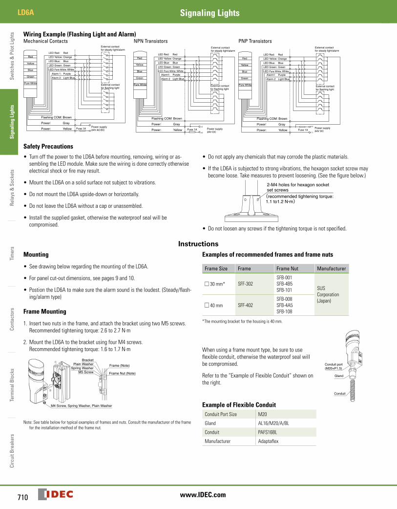
Wiring Example (Flashing Light and Alarm)Mechanical Contacts NPN Transistors PNP Transistors
Flashing COM: Brown
Power: Gray
Power: Yellow Fuse 1A Power supply24V AC/DC
Red
Yellow
Green
Blue
Pure White
LED Red: RedLED Yellow: OrangeLED Blue: BlueLED Green: GreenLED Pure White: White Alarm 1: Purple Alarm 2: Light Blue
External contact for steady light/alarm
External contact for flashing light
(–)
(+)
LED Red: RedLED Yellow: OrangeLED Blue: BlueLED Green: GreenLED Pure White: White Alarm1: Purple Alarm 2 Light Blue
Red
Yellow
Green
Blue
Pure White
External contact for steady light/alarm
External contact for flashing light
Flashing COM: Brown
Power: Gray
Power: Yellow Fuse 1A Power supply24V DC
LED Red: RedLED Yellow: OrangeLED Blue: BlueLED Green: GreenLED Pure White: White Alarm1: Purple Alarm 2 Light Blue
Red
Yellow
Green
Blue
Pure White
Flashing COM: Brown
Power: Gray
Power: Yellow(+)
(–)
Power supply24V DCFuse 1A
External contact for steady light/alarm
External contact for flashing light
Safety Precautions
• Turn off the power to the LD6A before mounting, removing, wiring or as-sembling the LED module. Make sure the wiring is done correctly otherwise electrical shock or fire may result.
• Mount the LD6A on a solid surface not subject to vibrations.
• Do not mount the LD6A upside-down or horizontally.
• Do not leave the LD6A without a cap or unassembled.
• Install the supplied gasket, otherwise the waterproof seal will be compromised.
• Do not apply any chemicals that may corrode the plastic materials.
• If the LD6A is subjected to strong vibrations, the hexagon socket screw may become loose. Take measures to prevent loosening. (See the figure below.)
2-M4 holes for hexagon socket set screws(recommended tightening torque:1.1 to1.2 N・m)
• Do not loosen any screws if the tightening torque is not specified.
InstructionsMounting
• See drawing below regarding the mounting of the LD6A.
• For panel cut-out dimensions, see pages 9 and 10.
• Postion the LD6A to make sure the alarm sound is the loudest. (Steady/flash-ing/alarm type)
Frame Mounting
1. Insert two nuts in the frame, and attach the bracket using two M5 screws. Recommended tightening torque: 2.6 to 2.7 N·m
2. Mount the LD6A to the bracket using four M4 screws. Recommended tightening torque: 1.6 to 1.7 N·m
Frame (Note)
Frame Nut (Note)
BracketPlain Washer
Spring WasherM5 Screw
M4 Screw, Spring Washer, Plain Washer
➀
➁
Note: See table below for typical examples of frames and nuts. Consult the manufacturer of the frame for the installation method of the frame nut.
Examples of recommended frames and frame nuts
Frame Size Frame Frame Nut Manufacturer
30 mm* SFF-302SFB-001SFB-4B5SFB-101 SUS
Corporation (Japan)
40 mm SFF-402SFB-008SFB-4A5SFB-108
*The mounting bracket for the housing is 40 mm.
When using a frame mount type, be sure to use flexible conduit, otherwise the waterproof seal will be compromised.
Refer to the “Example of Flexible Conduit” shown on the right.
Gland
Conduit
Conduit port(M20×P1.5)
Example of Flexible ConduitConduit Port Size M20
Gland AL16/M20/A/BL
Conduit PAFS16BL
Manufacturer Adaptaflex

Switches &
Pilot LightsSignaling Lights
Relays & Sockets
Timers
ContactorsTerm
inal BlocksCircuit Breakers
711800-262-IDEC (4332) • USA & Canada
LD6ASignaling Lights
Wall Mounting
1. Make four tapped holes in the mounting panel and mount the bracket and gasket using four screws (M4 x 20). Recommended tightening torque: 1.6 to 1.7 N·m
2. Mount the LD6A to the bracket using four screws (M4 x 8). Recommended tightening torque: 1.6 to 1.7 N·m
Panel
Nut
GasketBracket
Plain WasherSpring Washer
M4 Screw (20 mm)
M4 Screw (8 mm), Spring Washer, Plain Washer
➁
➀
Direct Mounting
Recommended tightening torque: 2.6 to 2.7 N·m Panel
M5 ScrewSpring WasherPlain WasherO-ringBaseGasketNut
Pole Mounting (with base)
The pole mount type can be installed in four ways. The recommended mounting method (pattern A from page 9 or 10) is described below.
Recommended tightening torque: 2.6 to 2.7 N·m (M5 screw)
Pole Mounting (with L-shaped bracket)
1. Using L-shaped bracket Recommended tightening torque: 10 to 11 N·m (M10) Recommended tightening torque: 25 to 26 N·m (M22)
2. Not using L-shaped bracket Remove the bushing, hexagonal nut (M22), plain washer, and L-shaped bracket from the LD6A and install in the following order: plain washer, hex-agonal nut (M22), and bushing. Recommended tightening torque: 25 to 26 N·m (M22)
1. Using L-shaped bracket 2. Not using L-shaped bracket
Hexagonal nut (M22)Hexagonal bolt∗ (M10)
Hexagonal nut∗(M10)Spring washer∗Plain washer∗
Plain washer
Bushing
Hexagonal nut (M22)
The parts marked with * are not supplied and should be provided by the user.
Replacement and Addition of LED Modules
• Make sure to turn power off.
• Insert a flat screwdriver into the cap recess as shown below, lift up the cap, and remove with your hands. Use a flat screwdriver with maximum 1-mm thick and 7-mm wide tip.
• Remove the center screw before reassembling the LED modules.
• When assembling the LED modules, make sure to align the recess of the cap with the recess of the LED module. Otherwise, damage may result. Recommended tightening torque: 0.4 to 0.5 N·m.
Insert flat screwdriver into recess 1
2 3
Recess
Recess
Recess
Recess
LED module
Top Cap
Gasket
• Note the correct orientation when assembling the LED modules.
• Tighten the screws to the recommended tightening torque. The LED module may be damaged if the screw is loose during operation.
• Do not touch the metal plug on the LED module. Otherwise, LED elements maybe damaged due to static electricity.
• Use a maximum of 5 tiers.
• Select the correct screw length depending on the number of tiers.
• Do not remove the gasket from the LED module. Otherwise, the waterproof seal will be compromised.
Wiring
• For wiring, see the wiring diagrams on pages 708 and 710.
• Incorrect wiring may damage the internal circuit.
• Be sure to insulate unused wires.
• Connect a 1A fuse to the power line as shown in the Wiring Examples on pages 708 and 710.
• Use a UL listed external fuse holder.
• Use a class 2 power supply only.
• When using LED modules of the same color for two or more tiers, determine contact capacity in referencet to the LED current, because only one wire is used to light all tiers of the same color.
• Do not apply voltage to flashing (brown) lines.
• Do not connect flashing (brown) line to the power lines. The internal circuit may be damaged.
• Do not turn on steady and flashing circuits simultaneously.
• Do not turn on alarms 1 and 2 simultaneously.
Pole Stand
4-M5 Mounting Hole (recommended)
3-M4 Mounting Hole4-M4 Mounting Hole
4-M5 MountingHole
M5 ScrewO-ringPole StandGasketPanelPlain WasherSpring WasherNut

Switc
hes
& P
ilot L
ight
sSi
gnal
ing
Ligh
tsRe
lays
& S
ocke
tsTi
mer
sCo
ntac
tors
Term
inal
Blo
cks
Circ
uit B
reak
ers
LD6A Signaling Lights
712 www.IDEC.com
Wire ColorWire Color Steady Steady, Flashing, Alarm
Red LED Module – Red LED Module – Red
Orange LED Module – Yellow LED Module – Yellow
Blue LED Module – Blue LED Module – Blue
Green LED Module – Green LED Module – Green
White LED Module – White LED Module – White
Purple — Alarm 1
Light Blue — Alarm 2
Brown — Flashing COM
Gray — Power Line
Yellow Power Line Power Line
For information on external contacts, see “External Contact Ratings” on page 707.
Alarm Volume Adjustment
• Move the volume adjustment to the right or left to change the volume.
• When the adjustment lever is all the way to the right the volume is at its maximum.
• The adjustment lever may be damaged if forced open or closed.
Max.Min.
Alarm volumeadjustment lever
High Temperature Limitations
The external temperature cannot exceed 50ºC when all tiers are lit at the same time in the following combinations:
1. Three tiers Two or more tiers of blue and green (example: Red-Green-Blue, Green-Green-Red)
2. Four or five tiers (example: Red-Yellow-Green-White, Red-Yellow-Blue-Green-White)