signalling unit sace pr010/k4.2. reset signalling “reset signalling” causes the repositioning of...
TRANSCRIPT

SIGNALLING UNITSACE PR010/K
Titletitolo Manuale d’uso Lang.
LinguaIT
Rev. L0633 Apparatus SACE PR010/K Scale
Mod. Apparecchio Scala
ÿþþ� ABB SACEDoc. No.N° Doc RH0043.002
Sh. NoN° Pag..
1/20

Rev. L0633 Apparatus SACE PR010/K Sh. No.
Mod. Apparecchio N° Pag.
ÿþþ� ABB SACEDoc. No.N° Doc RH0043.002
Sh. NoN° Pag..
2/20
CONTENTS
1. GENERAL .................................................................................................................................................................3
1.1. INTRODUCTION.........................................................................................................................................................31.2. APPLICABLE SCENARIOS...........................................................................................................................................3
2. TECHNICAL CHARACTERISTICS......................................................................................................................4
2.1. ELECTRICAL CHARACTERISTICS................................................................................................................................42.1.1. Auxiliary supply...............................................................................................................................................4
2.2. MECHANICAL CHARACTERISTICS..............................................................................................................................42.3. ENVIRONMENTAL CONDITIONS.................................................................................................................................42.4. COMMUNICATION BUS .............................................................................................................................................42.5. INTERNAL RELAY CHARACTERISTICS........................................................................................................................4
3. USER INTERFACE ..................................................................................................................................................5
3.1. USE OF PUSH-BUTTON ..............................................................................................................................................53.2. OPTICAL SIGNALLING................................................................................................................................................53.3. TERMINAL BLOCK.....................................................................................................................................................6
4. SPECIAL FUNCTIONS ...........................................................................................................................................6
4.1. RESET.......................................................................................................................................................................64.2. RESET SIGNALLING...................................................................................................................................................64.3. SELF-TEST FUNCTION................................................................................................................................................64.4. STAND-BY FUNCTION................................................................................................................................................6
5. PUTTING INTO SERVICE .....................................................................................................................................7
5.1. INSTALLATION INSTRUCTIONS..................................................................................................................................75.2. CONNECTIONS..........................................................................................................................................................75.3. DIP-SWITCH SETTINGS..............................................................................................................................................8
5.3.1. Example of dip-switch setting..........................................................................................................................95.3.2. Default settings................................................................................................................................................95.3.3. Serial Number..................................................................................................................................................9
5.4. SACE PR010/KWITH SACE PR112UNIT (WITH LAST LETTER OF SERIAL NUMBERA…E)..........................105.4.1. Dip-switch settings ........................................................................................................................................105.4.2. Signalling.......................................................................................................................................................10
5.5. SACE PR010/KWITH SACE PR112UNIT (WITH LAST LETTER OF SERIAL NUMBERF…Z)...........................115.5.1. Dip-switch settings ........................................................................................................................................115.5.2. Signalling.......................................................................................................................................................11
5.6. SACE PR010/KWITH SACE PR113UNIT.............................................................................................................125.6.1. Dip-switch settings ........................................................................................................................................125.6.2. Signalling.......................................................................................................................................................135.6.3. Connection of 3 SACE PR010/K units with SACE PR113/P .........................................................................13
5.7. SACE PR010/KWITH SACE PR212/PUNIT .........................................................................................................145.7.1. Dip-switch settings ........................................................................................................................................145.7.2. Signalling.......................................................................................................................................................14
5.8. SACE PR010/KWITH SACE PR212/MPUNIT ......................................................................................................155.8.1. Dip-switch settings ........................................................................................................................................155.8.2. Signalling.......................................................................................................................................................15
5.9. APPLICABLE ELECTRICAL DIAGRAMS......................................................................................................................165.9.1. PR112 (or PR113) + PR010/K......................................................................................................................165.9.2. PR113/P + 3 PR010/K units..........................................................................................................................175.9.3. PR212/P (or PR212/MP) + PR010/K............................................................................................................185.9.4. PR212/P + PR212/D-L (or PR212/D–M) + PR010/K ..................................................................................185.9.5. Electrical diagram legend .............................................................................................................................19
6. TROUBLESHOOTING..........................................................................................................................................19
6.1. IN CASE OF FAULT...................................................................................................................................................20

Rev. L0633 Apparatus SACE PR010/K Sh. No.
Mod. Apparecchio N° Pag.
ÿþþ� ABB SACEDoc. No.N° Doc RH0043.002
Sh. NoN° Pag..
3/20
1. General
1.1. IntroductionCarefully read the whole of this document before installation and start-up of the PR010/K unit.
The PR010/K unit, connected to the protection units from the Isomax series (PR212/P or PR212/MP) and Emax(PR112 or PR113), allows the signalling of various events which can be verified during normal operation of theconnected protection unit.In the case of these events, the PR010/K unit operates the internal relays fitted with powered contacts (par.2.5).
The PR010/K unit also features (only in combination with the protection relays fitted to the Emax series) the ‘Loadcontrol’ function. For further information on the functioning of the ‘Load control’ function, as well as the settingsnecessary to use this protection, consult the users manual for the protection relays (PR112 e PR113).
For the correct use and operation of protection units interfaced with the PR010/K unit, the following documents mustbe consulted;• Sheet kit protection unit PR212/P (doc. n° RH0062)• Sheet kit protection unit PR212/MP (doc. n° RH0063)• Instruction manual protection unit PR112/P (doc. n° RH0288 for version IEC or RH0109 per version UL)• Instruction manual protection unit PR113/P (doc. n° RH0288 for version IEC or RH0109 for version UL)• ABB SACE Isomax technical catalogue• ABB SACE Emax technical catalogue
1.2. Applicable scenariosThe following diagram shows the applicable scenarios and the relationship between:• Protection unit (Isomax series or Emax)**• PR010/K unit• Communication unit (Isomax series or Emax)**
Note: ** for Emax series, the protection unit contains an internal communication unit(when required).
Connections between various units, depending on the scenario (Master or Slave mode are shown as indications only,the specific cabling must be carried out according to official ABB SACE documentation.
protection unit(Isomax-Emax)
signalling unitPR010/K
internal bus
Scenario“Master mode”with PR010/K +protection unit
protection unit(Isomax-Emax)
communicationunit
(Isomax-Emax)
remote supervisionsystem
ÿexternal bus
internal bussignalling unit
PR010/K
Scenario“Slave mode”with PR010/K +protection unit +
communication unit
Rev. L0633 Apparatus SACE PR010/K Sh. No.
Mod. Apparecchio N° Pag.
ÿþþ� ABB SACEDoc. No.N° Doc RH0043.002
Sh. NoN° Pag..
4/20
2. Technical characteristics
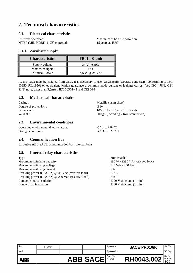
2.1. Electrical characteristicsEffective operation: Maximum of 6s after power on.MTBF (MIL-HDBK-217E) expected: 15 years at 45°C
2.1.1. Auxiliary supply
Characteristics PR010/K unit
Supply voltage 24 Vdc±20%Maximum ripple ± 5%Nominal Power 4,5 W @ 24 Vdc
As the Vaux must be isolated from earth, it is necessary to use ‘galvanically separate converters’ conforming to IEC60950 (UL1950) or equivalent [which guarantee a common mode current or leakage current (see IEC 478/1, CEI22/3) not greater than 3,5mA], IEC 60364-41 and CEI 64-8.
2.2. Mechanical characteristicsCasing : Metallic (1mm sheet)Degree of protection : IP20Dimensions : 100 x 45 x 120 mm (h x w x d)Weight : 500 gr. (including 2 front connectors)
2.3. Environmental conditionsOperating environmental temperature: -5 °C ... +70 °CStorage conditions: -40 °C ... +90 °C
2.4. Communication BusExclusive ABB SACE communication bus (internal bus)
2.5. Internal relay characteristicsType MonostableMaximum switching capacity 150 W / 1250 VA (resistive load)Maximum switching voltage 130 Vdc / 250 VacMaximum switching current 5 ABreaking power (UL/CSA) @ 48 Vdc (resistive load) 0.9 ABreaking power (UL/CSA) @ 230 Vac (resistive load) 5 AContact/contact insulation 1000 V efficient (1 min.)Contact/coil insulation 2000 V efficient (1 min.)

Rev. L0633 Apparatus SACE PR010/K Sh. No.
Mod. Apparecchio N° Pag.
ÿþþ� ABB SACEDoc. No.N° Doc RH0043.002
Sh. NoN° Pag..
5/20
3. User interface
The front of the unit consists of one push-button, five LEDs, and two terminal blocks.
3.1. Use of push-button• Reset:Press to carry out reset of PR010/K hardware.
3.2. Optical signalling
Functioning conditions of PR010/KLED state
LED L(green)
LED S(green)
LED I(green)
LED G(green)
LED Tx (Int Bus)(yellow)
OffContact K51/1
openContact K51/2
openContact K51/3
openContact K51/4
openanomalous situation
OnContact K51/1
closedContact K51/2
closedContact K51/3
closedContact K51/4
closedanomalous situation
Fast flashing� OKFlashing -- -- -- -- with freq. = 2Hz
� see ***
*** Flashing at 2Hz one of the following can be verified:- Communication not present- SACE PR010/K in stand-by mode or Self-test- Connected protection unit not recognised
Terminals (see par.3.3)
Push-button (seepar.3.1)
LEDs (see par.3.2)
This area is designed for thepossible application of
customised adhesive label(see par.3.2)

Rev. L0633 Apparatus SACE PR010/K Sh. No.
Mod. Apparecchio N° Pag.
ÿþþ� ABB SACEDoc. No.N° Doc RH0043.002
Sh. NoN° Pag..
6/20
• Any LED state which does not conform with the above probably indicates a malfunction of the SACE PR010/Kunit.
• The indications given in the above table are with Vaux present, and with the PR010/Knot in Self-test, andnot instand-by mode (see par.5.3).
• For further details of possible malfunction conditions see para.6.
In the case of the LEDs being designated a significance other than L, S, I and G (standard configuration) it is possibleto use a customised adhesive label (RE0314/001) supplied with the PR010/K unit.
3.3. Terminal blockConnections 1…18inputs and outputs of PR010/K unit (see par.5.2)
4. Special functions
4.1. ResetIt is possible to carry out a reset of the PR010/K unit, by pressing the ‘reset’ push-button situated on the front panel ofthe unit (see par. 3.1).This type of reset restarts the Sw of the PR010/K unit (the data memorised in the RAM is conserved).
4.2. Reset signalling“Reset signalling” causes the repositioning of the internal relays (K51) to rest conditions (contacts open) followingswitching (contacts closed) for protection function (trip).This reset can be carried out:- carrying out a reset (see par.4.1), if the applicable scenario is “PR010/K in Master mode” (see par.1.2).- sending a “Trip Reset “ command from the remote supervision system.- pressing the RESET push-button on the front of the unit, if the applicable scenario is “PR010/K in Slave mode”
(see par.1.2) and only for Emax series protection units.
4.3. Self-test functionTo carry out the self-test, dip-switch n°1 must be set to ON (see par. 5.3.1) and the reset button pressed.The self-test switches, in succession, all 8 internal relays, carrying out a functional test on each.The Tx LED lights with each switching. When the switching is completed the LED flashes at a frequency of 2 Hz.The self-test takes approx. 10 s, after which the SACE PR010/K unit automatically returns to normal operation.
4.4. Stand-by functionTo select Stand-by mode, dip-switch n°8 must be set to ‘ON’ (see par.5.3.1) and the reset button pressed; in this modethe internal relays will not be switched.This function is useful when the protection unit is being tested (for example with PR010/T unit) and the switching ofthe relays of the PR010/K unit is not desired.
Areas to becustomised by user
Rev. L0633 Apparatus SACE PR010/K Sh. No.
Mod. Apparecchio N° Pag.
ÿþþ� ABB SACEDoc. No.N° Doc RH0043.002
Sh. NoN° Pag..
7/20
5. Putting into service
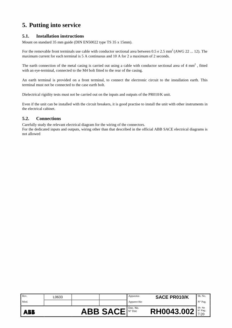
5.1. Installation instructionsMount on standard 35 mm guide (DIN EN50022 type TS 35 x 15mm).
For the removable front terminals use cable with conductor sectional area between 0.5 e 2.5 mm2 (AWG 22 ... 12). Themaximum current for each terminal is 5 A continuous and 10 A for 2 a maximum of 2 seconds.
The earth connection of the metal casing is carried out using a cable with conductor sectional area of 4 mm2 , fittedwith an eye-terminal, connected to the M4 bolt fitted to the rear of the casing.
An earth terminal is provided on a front terminal, to connect the electronic circuit to the installation earth. Thisterminal must not be connected to the case earth bolt.
Dielectrical rigidity tests must not be carried out on the inputs and outputs of the PR010/K unit.
Even if the unit can be installed with the circuit breakers, it is good practise to install the unit with other instruments inthe electrical cabinet.
5.2. ConnectionsCarefully study the relevant electrical diagram for the wiring of the connectors.For the dedicated inputs and outputs, wiring other than that described in the official ABB SACE electrical diagrams isnot allowed

Rev. L0633 Apparatus SACE PR010/K Sh. No.
Mod. Apparecchio N° Pag.
ÿþþ� ABB SACEDoc. No.N° Doc RH0043.002
Sh. NoN° Pag..
8/20
5.3. Dip-switch settings
After correctly wiring all of the frontal connections and the rear earth connection, it is necessary to set the dip-switcheswhich are positioned on the top of the PR010/K unit.The criteria for the wiring of the frontal connections and for the dip-switch settings depend upon the type of protectionunit connected to the PR010/K unit; the following paragraphs detail the possible configurations.N.B.: dip-switch reading is carried out at “power on” or after a hardware reset (pressing front "Reset" button) and isactive after the start-up phase.
Dip-Sw n°dip-switchdescription
Settable values Note
1 Test0 = Self-test deactivated1 = Self-test activated
The “Self-test” function switches all 8 internal relays insuccession, carrying out a functional test.The Tx LED lights in combination with the switching, once thetest has been carried out, the LED flashes at a frequency of2Hz.For the normal functioning mode, this dip-switch must be set toOFF.
2
3
4
5
K51Configuration
0 = Matching signalling ofevent A
1 = Matching signalling ofevent B
Depending upon the type of protection unit connected to thePR010/K unit, the event associated with the switching of somecontacts (K51), can be selected from two alternatives (A or B).N.B. For some protection units an alternative which can beselected using the dip-switches is not provided, in this case theevent associated with each contact is unique (defined by ABBSACE), and is independent of the position of the dip-switch (0or1).
6 Mode0 = Slave,
1 = Master.
Setting in Master mode is necessary when the PR010/K unit iscombined with a protection unit without a communication unit(see “scenario PR010/K in Master mode” par.1.2).Setting in Slave mode is necessary when the PR010/K unit isconnected to a protection unit and a communication unit (see“scenario PR010/K in Slave mode” par.1.2).
7 Baud0 = 19.2 kbit/s,1 = 38.4 kbit/s.
The setting of the transmission speed must be equal to that ofthe connected protection unit (see par.5.4.1, 5.5.1, 5.6.1…).
8 State0 = Normal,
1 = Stand-by.
The Stand-by mode ensures that the K51 contacts do not switchunder any circumstances, even if the conditions which wouldnormally cause switching exist.Normal functioning mode ensures that the K51 contacts switchwhen the conditions which normally cause switching exist(normal functioning)If set to 1 (Stand-by), the unit is not able to carry out a self-test!For normal functioning, this dip-switch must be set to Off.
Rev. L0633 Apparatus SACE PR010/K Sh. No.
Mod. Apparecchio N° Pag.
ÿþþ� ABB SACEDoc. No.N° Doc RH0043.002
Sh. NoN° Pag..
9/20
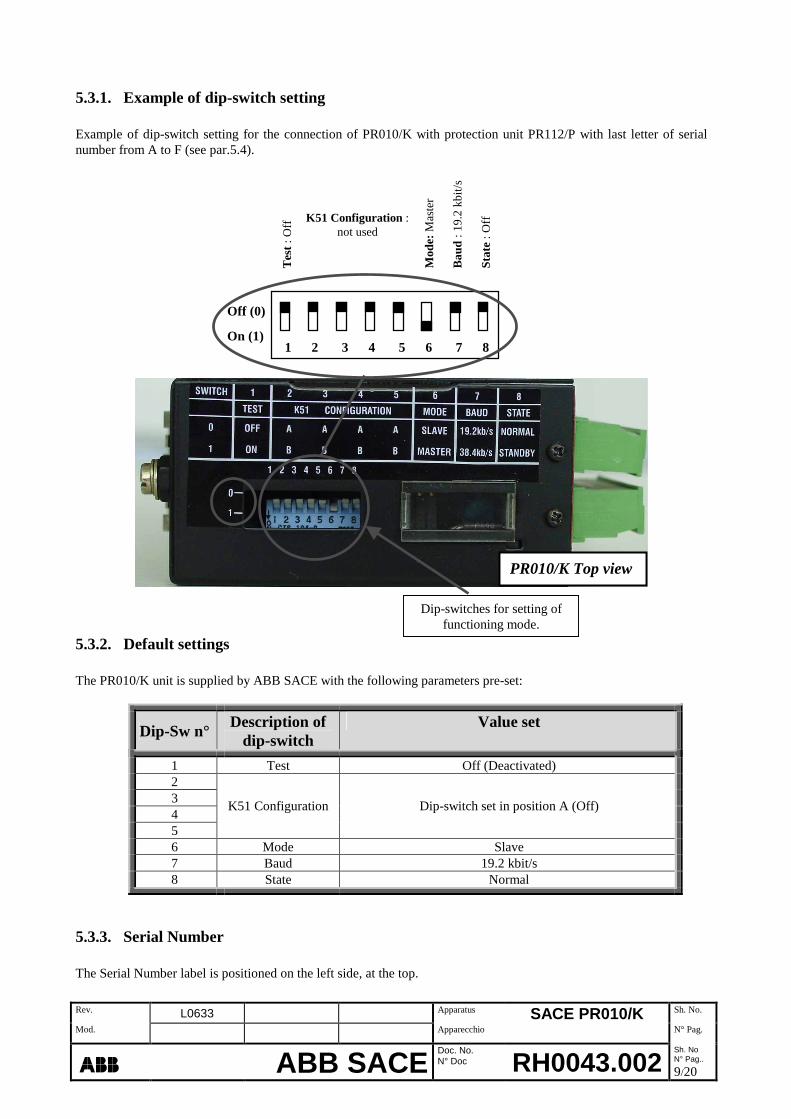
5.3.1. Example of dip-switch setting
Example of dip-switch setting for the connection of PR010/K with protection unit PR112/P with last letter of serialnumber from A to F (see par.5.4).
Tes
t:O
ff K51 Configuration :not used
Mod
e:M
aste
r
Bau
d:1
9.2
kbit/
s
Sta
te:O
ff
5.3.2. Default settings
The PR010/K unit is supplied by ABB SACE with the following parameters pre-set:
Dip-Sw n°Description of
dip-switchValue set
1 Test Off (Deactivated)2345
K51 Configuration Dip-switch set in position A (Off)
6 Mode Slave7 Baud 19.2 kbit/s8 State Normal
5.3.3. Serial Number
The Serial Number label is positioned on the left side, at the top.
Off (0)
On (1)1 2 3 4 5 6 7 8
Dip-switches for setting offunctioning mode.
PR010/K Top view

Rev. L0633 Apparatus SACE PR010/K Sh. No.
Mod. Apparecchio N° Pag.
ÿþþ� ABB SACEDoc. No.N° Doc RH0043.002
Sh. NoN° Pag..
10/20
5.4. SACE PR010/K with SACE PR112 unit(with last letter of serial number A…E)
5.4.1. Dip-switch settings
N°
Dip-Sw
Description of
dip-switch0 (Off) 1 (On) Note
1 Test Normal Self-testFor normal functioning mode, set this dip-switch to
OFF.2345
K51Configuration
- - Not used
6 Mode Slave MasterMaster if PR112/P + PR010/K.Slave if PR112/PD + PR010/K.
7 Baud Rate 19.2 kbit/s 38.4 kbit/s Set 19.2 kbit/s
8 State Normal Stand-byFor normal functioning mode, set this dip-switch to
OFF
Example of dip-switch settings for connection of PR010/K unit with SACE PR112/P protection unit.
Dip-switch n° 1 2 3 4 5 6 7 8
5.4.2. Signalling
The significance of signals (K51/1…K51/8) for protection unit SACE PR112 is as follows:
ContactN° Pin on unit
PR010/KEvent which causes closing of relay
K51/1 5 Alarm protection L (overload)
K51/2 6 Alarm protection S (selective short circuit)
K51/3 7 Alarm protection I (instantaneous short circuit)
K51/4 8 Alarm protection G (ground fault)
K51/5 9 Internal Bus communication problem (bus KO)
K51/6 10 Internal overheat alarm (T=85°C)
K51/7 12 CB trip alarm –TRIP–
K51/8 17 Pre-alarm function L (overload)
Off
On

Rev. L0633 Apparatus SACE PR010/K Sh. No.
Mod. Apparecchio N° Pag.
ÿþþ� ABB SACEDoc. No.N° Doc RH0043.002
Sh. NoN° Pag..
11/20
5.5. SACE PR010/K with SACE PR112 unit(with last letter of serial number F…Z)
5.5.1. Dip-switch settings
N°
Dip-Sw
Description of
dip-switch0 (Off) 1 (On) Note
1 Test Normal Self-testFor normal functioning mode, set this dip-switch to
OFF.
2K51/4
ConfigurationA
Alarmprotection G
BPre-alarmfunction L
3K51/5
ConfigurationA Bus KO B
Internaloverheat
Functions (A or B)assigned to contact relay,
to be selected with corresponding dip-switch
45
- - - Not used
6 Mode Slave MasterMaster if PR112/P + PR010/K.Slave if PR112/PD + PR010/K.
7 Baud Rate 19.2 kbit/s 38.4 kbit/s Set 19.2 kbit/s
8 State Normal Stand-byFor normal functioning mode, set this dip-switch to
OFF.
Example of dip-switch settings for connection of PR010/K unit with SACE PR112/P protection unit.
Dip-switch n° 1 2 3 4 5 6 7 8
5.5.2. Signalling
The significance of signals (K51/1…K51/8) for protection unit SACE PR112 is as follows:
ContactN° Pin on unit
PR010/KEvent which causes closing of relay
K51/1 5 Alarm protection L (overload)
K51/2 6 Alarm protection S (selective short circuit)
K51/3 7 Alarm protection I (instantaneous short circuit)
A Alarm protection G (ground fault)K51/4 * 8B Pre-alarm function L (overload)A Internal Bus communication problem (bus KO)
K51/5 * 9B Internal overheat alarm (T=85°C)
K51/6 10 Load check LC1
K51/7 12 CB trip alarm –TRIP–
K51/8 17 Load check LC2
“*” The reason for the closing of these contacts (K51/4 e K51/5) depends upon the configuration, set via the dip-switch (event A or event B), of the PR010/K unit (see par.5.3).
Off
On
Rev. L0633 Apparatus SACE PR010/K Sh. No.
Mod. Apparecchio N° Pag.
ÿþþ� ABB SACEDoc. No.N° Doc RH0043.002
Sh. NoN° Pag..
12/20
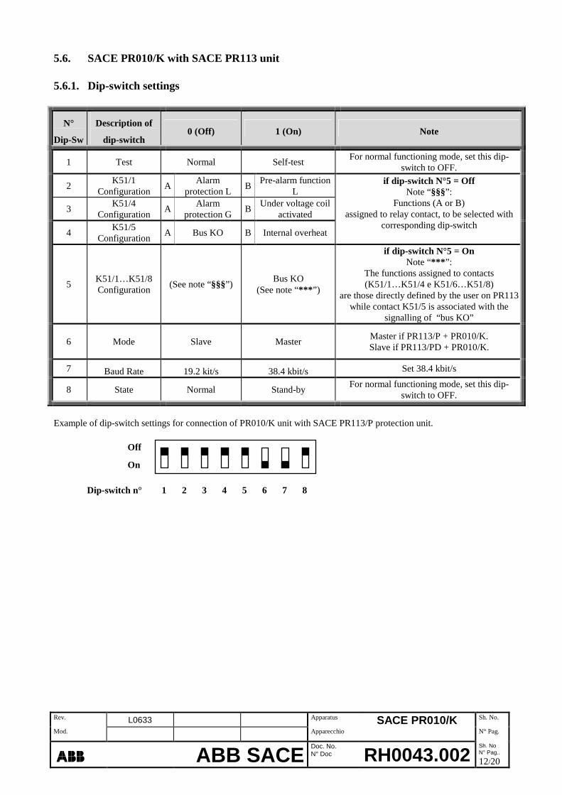
5.6. SACE PR010/K with SACE PR113 unit
5.6.1. Dip-switch settings
N°
Dip-Sw
Description of
dip-switch0 (Off) 1 (On) Note
1 Test Normal Self-testFor normal functioning mode, set this dip-
switch to OFF.
2K51/1
ConfigurationA
Alarmprotection L
BPre-alarm function
L
3K51/4
ConfigurationA
Alarmprotection G
BUnder voltage coil
activated
4K51/5
ConfigurationA Bus KO B Internal overheat
if dip-switch N°5 = OffNote “§§§”:
Functions (A or B)assigned to relay contact, to be selected with
corresponding dip-switch
5K51/1…K51/8Configuration
(See note “§§§”)Bus KO
(See note “*** ”)
if dip-switch N°5 = OnNote “*** ”:
The functions assigned to contacts(K51/1…K51/4 e K51/6…K51/8)
are those directly defined by the user on PR113while contact K51/5 is associated with the
signalling of “bus KO”
6 Mode Slave MasterMaster if PR113/P + PR010/K.Slave if PR113/PD + PR010/K.
7 Baud Rate 19.2 kit/s 38.4 kbit/s Set 38.4 kbit/s
8 State Normal Stand-byFor normal functioning mode, set this dip-
switch to OFF.
Example of dip-switch settings for connection of PR010/K unit with SACE PR113/P protection unit.
Dip-switch n° 1 2 3 4 5 6 7 8
Off
On

Rev. L0633 Apparatus SACE PR010/K Sh. No.
Mod. Apparecchio N° Pag.
ÿþþ� ABB SACEDoc. No.N° Doc RH0043.002
Sh. NoN° Pag..
13/20
5.6.2. Signalling
The significance of signals (K51/1…K51/8) for the SACE PR113 protection unit is as follows:
ContactN° Pin on unit
PR010/KEvent which causes closing of relay
A Alarm protection L (overload)
B Pre-alarm function L (overload)K51/1* 5
§§ Configured by user on PR113 unit
Alarm protection S (selective short circuit)K51/2 6§§ Configured by user on PR113 unit
Alarm protection I (instantaneous short circuit)K51/3 7§§ Configured by user on PR113 unit
A Alarm protection G (ground fault)B Under voltage coil activatedK51/4* 8
§§ Configured by user on PR113 unit
A Internal Bus communication problem (bus KO)B Internal overheat alarm (T=85°C)K51/5* 9§§ Internal Bus communication problem (bus KO)
Load check LC1K51/6 10
§§ Configured by user on PR113 unit
CB trip alarm –TRIP–K51/7 12
§§ Configured by user on PR113 unitLoad check LC2
K51/8 17§§ Configured by user on PR113 unit
“* ”The reason for the closing of these contacts (K51/1, K51/4 and K51/5) depends upon the configuration (event A orevent B) set via the dip-switch of the PR010/K unit, only if dip-sw N°5 is set to OFF (see par.5.6.1).
“§§” In the case of dip-sw N°5 set to ON all contacts (K51/1…K51/8) are exclusively associated with the function seton the PR113 unit by the user, except contact K51/5 which shows ‘Internal Bus communication problem (bus KO)’.
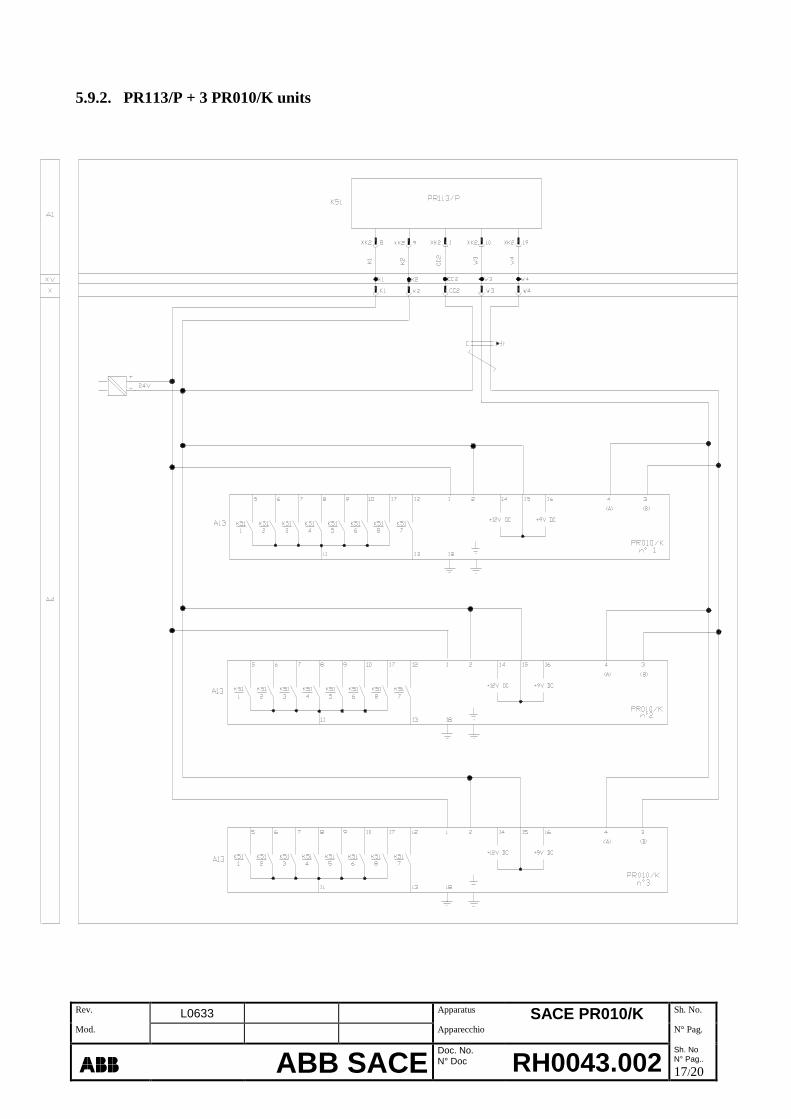
5.6.3. Connection of 3 SACE PR010/K units with SACE PR113/P
It is possible to connect two or three SACE PR010/K units with a PR113/P unit (see par. 5.9.2).
The only condition being that one PR010/K unit must be configured as Master, with the other(s) configured as Slave.
In this way it is possible to activate up to (7 + 8 + 3 =) 18 contacts without potential (relay), plus 6 replicated (seeEmax manual).

Rev. L0633 Apparatus SACE PR010/K Sh. No.
Mod. Apparecchio N° Pag.
ÿþþ� ABB SACEDoc. No.N° Doc RH0043.002
Sh. NoN° Pag..
14/20
5.7. SACE PR010/K with SACE PR212/P unit
5.7.1. Dip-switch settings
N°
Dip-Sw
Description of
dip-switch0 (Off) 1 (On) Note
1 Test Normal Self-test For normal functioning mode, set this dip-switch to OFF.2345
- - - Not used
6 Mode Slave MasterMaster if PR212/P + PR010/K
Slave if PR212/P +PR212/D-L (or PR212/D-M) + PR010/K
7 Baud Rate 19.2 kbit/s 38.4 kbit/s Set 38.4 kbit/s8 State Normal Stand-by For normal functioning mode, set this dip-switch to OFF.
Example of dip-switch settings for connection of PR010/K with SACE PR212/P protection unit.
1 2 3 4 5 6 7 8
5.7.2. Signalling
The significance of signals (K51/1…K51/8) for the SACE PR212/P protection unit is as follows:
ContactN° Pin on
unit PR010/KEvent which causes closing of relay
K51/1 5 Alarm protection L (overload)
K51/2 6 Alarm protection S (selective short circuit)
K51/3 7 Alarm protection I (instantaneous short circuit)
K51/4 8 Alarm protection G (ground fault)
K51/5 9 Internal Bus communication problem (bus KO)
K51/6 10 Not Used
K51/7 12 CB trip alarm –TRIP–
K51/8 17 Pre-alarm function L (overload)
Off
On

Rev. L0633 Apparatus SACE PR010/K Sh. No.
Mod. Apparecchio N° Pag.
ÿþþ� ABB SACEDoc. No.N° Doc RH0043.002
Sh. NoN° Pag..
15/20
5.8. SACE PR010/K with SACE PR212/MP unit
5.8.1. Dip-switch settings
N°
Dip-Sw
Description of
dip-switch0 (Off) 1 (On) Note
1 Test Normal Self-testFor normal functioning mode, set this dip-switch to
OFF.2 K51/4 Function U Protection WC Protection3 K51/6 Function PTC Protection G.P. Protection4 K51/8 Function L Pre-alarm Backup Protection
Functions (A or B)assigned to relay contact, to be selected with
corresponding dip-switch
5 - - - Not used6 Mode Slave Master Set Master7 Baud Rate 19.2 kbit/s 38.4 kbit/s Set 38.4 kbit/s
8 State Normal Stand-byFor normal functioning mode, set this dip-switch to
OFF.
Example of dip-switch settings for connection of PR010/K unit with SACE PR212/MP protection unit.
1 2 3 4 5 6 7 8
5.8.2. SignallingThe significance of signals (K51/1…K51/8) for the SACE PR212/MP protection unit is as follows:
ContactN° Pin on
unit PR010/KEvent which causes closing of relay
K51/1 5 Alarm protection L (overload)
K51/2 6 Alarm protection R (rotor stuck)
K51/3 7 Alarm protection I (instantaneous short circuit)
A Alarm protection U (loss of phase)K51/4 * 8
B Alarm WC (contacts stuck )
K51/5 9 Internal Bus communication problem (bus KO)
A Alarm PTC (motor overheat )K51/6 * 10
B Activation of generic input contact (generic input G.P.)
K51/7 12 CB trip alarm –TRIP–
A Pre-alarm function L (overload)K51/8 * 17
B Backup alarm protection
“*”The reason for the closing of these contacts (K51/4 ,K51/6 e K51/8) ) depends upon the configuration (event A orevent B) set via the dip-switch of the PR010/K unit, (see par.5.3).
Off
On

Rev. L0633 Apparatus SACE PR010/K Sh. No.
Mod. Apparecchio N° Pag.
ÿþþ� ABB SACEDoc. No.N° Doc RH0043.002
Sh. NoN° Pag..
16/20
5.9. Applicable electrical diagrams
5.9.1. PR112 (or PR113) + PR010/K
Rev. L0633 Apparatus SACE PR010/K Sh. No.
Mod. Apparecchio N° Pag.
ÿþþ� ABB SACEDoc. No.N° Doc RH0043.002
Sh. NoN° Pag..
17/20
5.9.2. PR113/P + 3 PR010/K units

Rev. L0633 Apparatus SACE PR010/K Sh. No.
Mod. Apparecchio N° Pag.
ÿþþ� ABB SACEDoc. No.N° Doc RH0043.002
Sh. NoN° Pag..
18/20
5.9.3. PR212/P (or PR212/MP) + PR010/K
5.9.4. PR212/P + PR212/D-L (or PR212/D–M) + PR010/K

Rev. L0633 Apparatus SACE PR010/K Sh. No.
Mod. Apparecchio N° Pag.
ÿþþ� ABB SACEDoc. No.N° Doc RH0043.002
Sh. NoN° Pag..
19/20
5.9.5. Electrical diagram legend
A11 = Communication unit PR212/D-L (or PR212/D-M) for connection with a remote supervision system.A13 = Signalling unit PR010/KK51 = Protection unit PR212/P, PR212/MP, PR112/P, PR112/PD, PR113/P e PR113/PD.K51/1...8 = Internal relays of protection unit PR010/KX3-X4 = Connectors for auxiliary circuits of protection unit PR212/P or PR212/MPX = Connector for auxiliary circuits for removable breaker.XV = Terminals for auxiliary circuits for fixed breaker.
6. Troubleshooting
The following table details a range of typical operational situations, useful in the understanding and resolution ofhypothetical faults and malfunctions.
NB:• Before consulting the following table, check the LEDs on the front panel of the PR010/K unit for several seconds.
(wait until the end of the start up phase if the unit has just been switched on).• FN indicates normal functioning.

Rev. L0633 Apparatus SACE PR010/K Sh. No.
Mod. Apparecchio N° Pag.
ÿþþ� ABB SACEDoc. No.N° Doc RH0043.002
Sh. NoN° Pag..
20/20
N° Situation Possible cause Suggestions
1
Relays do not switch, even inpresence of conditionsrequired for switching (forexample an overload withprotection function L)
1. Relay in Stand-by or Self-test mode.
2. The unit has not been reset.
1.Set the Stand-by and Self-test dip-switchesto OFF, press the reset push-button on thefront panel of the PR010/K unit.
2. Carry out reset.
2The unit does not updateevents after a trip.
1. The unit has not been reset2. Internal Bus communication is
interrupted.
1.Press the reset push-button on the frontpanel of the PR010/K unit.
2.Check connections.
3The signalling cannot be resetafter a trip, despite pressingthe reset push-button.
The connected protection unit is aPR112/PD or PR113/PD and has notbeen reset.
1.Press the RESET push-button on the frontpanel of the PR112/PD or PR113/PD.
2.Send the “Trip reset” command from theremote supervision system.
4Flashing “Tx (Int Bus)” and/orswitching relay K51/5 (busKO) discontinued.
1. Bus conflict (2 master)2. Defective connection
1. Set Slave mode (dip-sw 6=Off)2. Check connections
5The LED “Tx (Int Bus)”flashes with a frequency of2Hz.
1. Communication not present.2. Unit PR010/K in Stand-by mode.3. Unit PR010/K in Self-test mode.4. Connected protection unit not
recognised.5. Incorrect communication speed set
(dip-switch “Baud”).
1. Check connections.2. FN3. FN4.Remove Vaux from PR010/K unit and from
the protection unit, then re-power the twounits simultaneously.
5. Set the correct value.
6 The LED “Tx (Int Bus)” is off.1. Wiring error.2. Anomalous situation.3. Aux voltage not present.
1. Check connections.2. Contact ABB SACE.3. Restore supply voltage.
7The LED “Tx (Int Bus)” is oncontinuously.
Anomalous situation. Contact ABB SACE
8The LED L (or S, I, or G)flashes.
The circulating current is close to thethreshold value (L, S, I or G) set on theprotection unit.
FN
6.1. In case of fault
If it is suspected that the PR010/K unit is faulty, is malfunctioning or has generated unpredicted commands, the used isadvised to carefully follow the following instructions:Prepare a brief description of the problem (when did it occur? How many times? Can the event be reproduced? ...)Note the type of load connected to the signalling unit (lamps, signalling relays, CBs, contacts, sirens etc..) and theserial number of the unit (see par.5.3.3).Send / communicate all the information, along with applicable electrical diagrams, to the nearest ABB SACE Servicecentre.
Providing complete and accurate information to ABB SACE Service will allow the problem to be analysed efficiently,thus permitting the client to receive complete and prompt service.