signals, circuits, and...
TRANSCRIPT

1
Signals, Circuits, and Computers
Part A
Winncy Du Fall 2012
Based on Dr. Ping Hsu’s original lecture notes

Types of Signals
• Analog: An analog signal is a continuous signal and is often represented by a V(t).
E.g., a dimmer light switch continuously increases/decreases the current.
• Digital : A digital signal is a binary signal.
E.g., an On/Off light switch applies a fixed, predetermined voltage.
2

3
Analog Signal Digital Signal
4
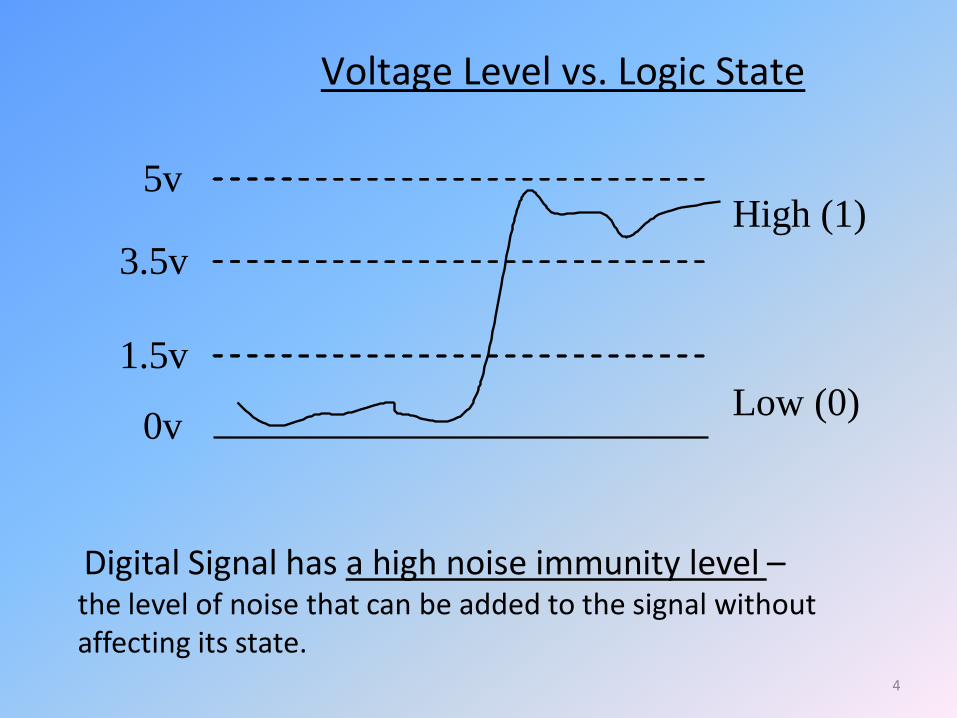
Voltage Level vs. Logic State
Low (0) 0v
High (1)
3.5v
5v
1.5v
Digital Signal has a high noise immunity level – the level of noise that can be added to the signal without affecting its state.

5
Analog Signal vs. Digital Signal
1. Analog signals
Pros: high resolution, efficient transmission
(1 wire, 1 signal), no delay, ‘real world’ signals.
Cons: Difficult to process (perform operations, storage), susceptible to noise.
2. Digital Signals
Pros: high immunity to noise, easy to process
Cons: needs a lot of ‘bits’ and circuits, data processing delay
6
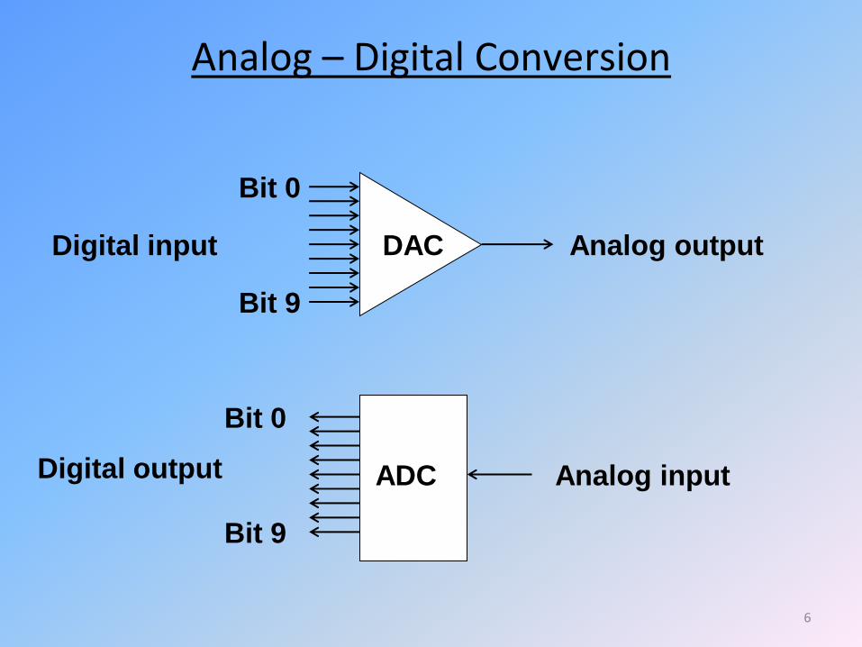
Analog – Digital Conversion
DAC
Bit 0
Bit 9
Analog output
Bit 0
Bit 9
Digital input
ADC Analog input Digital output

7
Q3. Which of the following is NOT an advantage of a digital signal:
A: Easy to perform math operation
B: Easy to store
C: High noise immunity
D: Need less circuitry.
E: All the above
8
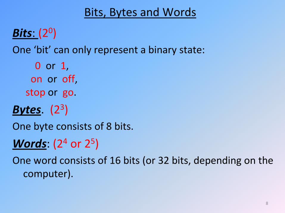
Bits, Bytes and Words
Bits: (20)
One ‘bit’ can only represent a binary state:
0 or 1, on or off, stop or go.
Bytes. (23)
One byte consists of 8 bits.
Words: (24 or 25)
One word consists of 16 bits (or 32 bits, depending on the computer).
9
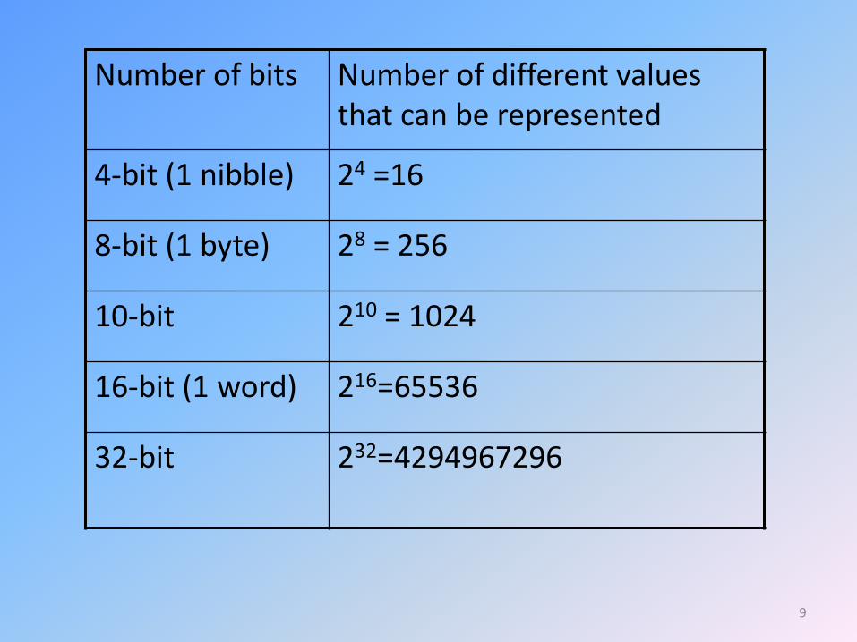
Number of bits Number of different values that can be represented
4-bit (1 nibble) 24 =16
8-bit (1 byte) 28 = 256
10-bit 210 = 1024
16-bit (1 word) 216=65536
32-bit 232=4294967296
10
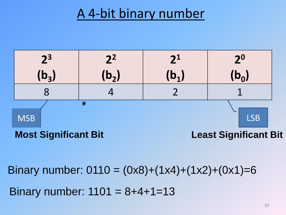
A 4-bit binary number
Binary number: 0110 = (0x8)+(1x4)+(1x2)+(0x1)=6
Binary number: 1101 = 8+4+1=13
Least Significant Bit
LSB MSB
323b222b121b020b
23
(b3) 22
(b2) 21
(b1) 20
(b0)
8 4 2 1
Most Significant Bit
11
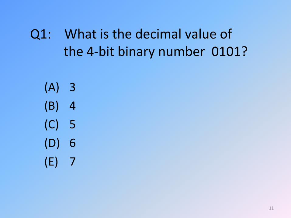
Q1: What is the decimal value of the 4-bit binary number 0101?
(A) 3
(B) 4
(C) 5
(D) 6
(E) 7

12
Q2. What do we call the bit that is in the leftmost position in a binary number?
A: SNB
B: LMB
C: MSB
D: LSB
E: USB

13
Binary Code
In a computer, a binary number is used to represent:
(1) Numerical values
(2) Characters and symbols (A, a, ¥,+, , @, ….)
(3) Picture, sound, video, etc.
(4) Machine language (for math operations, etc.)
(5) others …

14
4-bit Binary Code
Short hand
Notation-HEX
Numerical value represented
Machine language represented
0000 0 0 NOOP
0001 1 1 ADD
0010 2 2 SUB
0011 3 3 MUL
: : : :
1001 9 9 DIV
1010 A 10 COPY
1011 B 11 MOV
1100 C 12 AND
1101 D 13 OR
1110 E 14 SHIFT
1111 F 15 XOR
An example of a binary coding
15
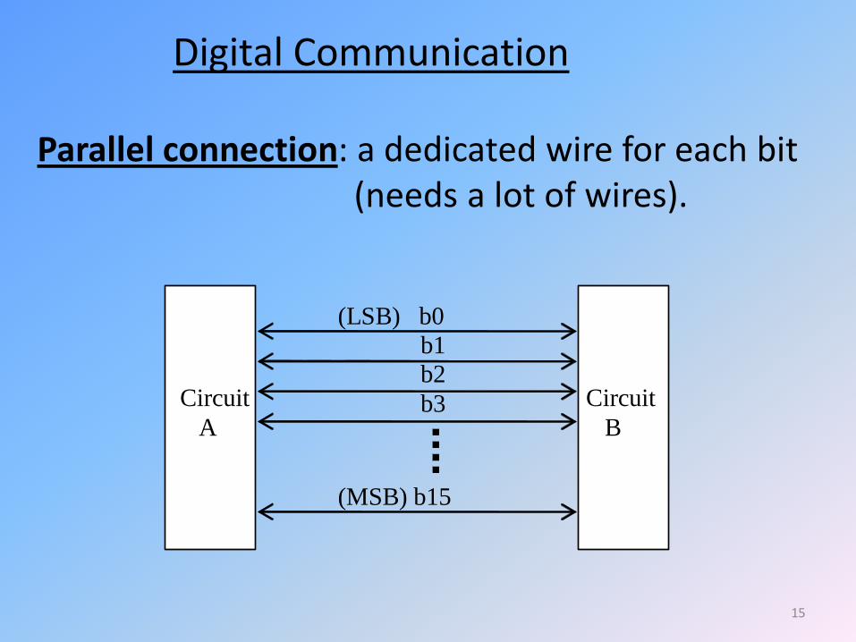
Digital Communication
b1
b2
b3
(LSB) b0
(MSB) b15
Circuit
A
Circuit
B
Parallel connection: a dedicated wire for each bit (needs a lot of wires).
16
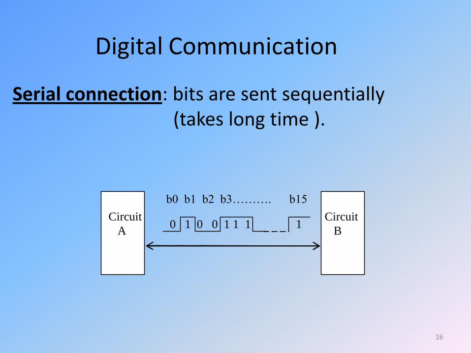
Digital Communication
b0 b1 b2 b3………. b15
Circuit
A
Circuit
B 0 1 0 0 1 1 1 1
Serial connection: bits are sent sequentially (takes long time ).

(c) P. Hsu 2007 17
Sending a byte or a word in parallel, sequentially (commonly used between circuits within a computer)
b1
b2
b3
b0
b15
Circuit
A
Circuit
B
b1
b2
b3
b0
b15
b1
b2
b3
b0
b15
byte1 byte2 byte3
(1μS) (2μS) (3μS)
Timing control circuit
18
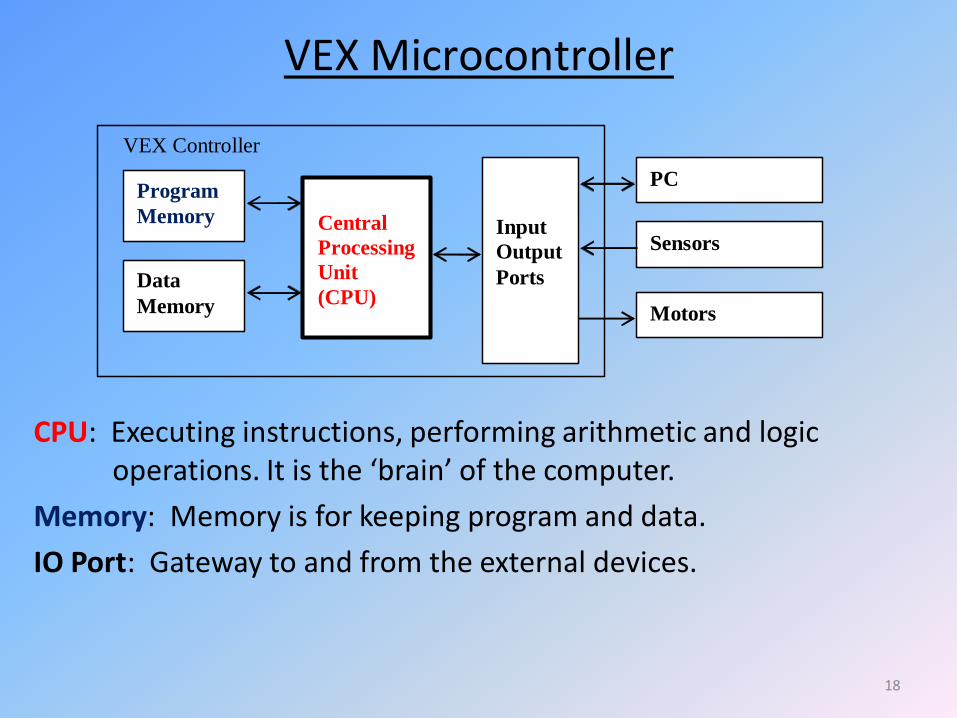
VEX Microcontroller
Central
Processing
Unit
(CPU)
Program
Memory
Data
Memory
Input
Output
Ports
PC
Sensors
Motors
VEX Controller
CPU: Executing instructions, performing arithmetic and logic operations. It is the ‘brain’ of the computer.
Memory: Memory is for keeping program and data.
IO Port: Gateway to and from the external devices.
19
Q4: What is the abbreviated name of the circuit in a computer that performs arithmetic operation?
A: USB
B: AOU
C: CPU
D: AIO
E: MOU
20
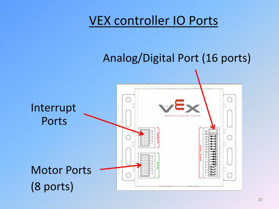
VEX controller IO Ports
Analog/Digital Port (16 ports)
Interrupt Ports
Motor Ports
(8 ports)

21
Infrared Receiver Board
1k/10kHz
Exposure
Intensity amplifier
selector
Tuning
circuit
Exposure
Control
Reset
sensitivity
0
1
2
3
4
5
6
7 counter
8
4
2
1 reset
count Infrared
detectors
VEX
Controller
AD1
AD14
AD15
AD16
For selecting one
of the 8 infrared
detectors
For each active
exposure control,
counter increases by 1.
Tune to 1kHz
or 10kHz