signed original on file at glosten - uw … · university of washington 2 the glosten associates,...
TRANSCRIPT

R/
Em
PreUnSe
File25 JRev
C
APP
1201 Western
C
/V Thoma
mergen
epared for iversity of Wattle, Washi
e No. 11156.01June 2012 v. –
HECKED:
WPr
PROVED:
TPr
Avenue, Suite 200,
Consulting Engineers
as G. Tho
ncy Tow
Washington ngton
1
William L. Mroject Naval Ar
Timothy S. rincipal-in-Cha
, Seattle, Washingto
s Serving the Marin
ompson
wing B
Moon, PE rchitect
Leach, PErge
on 98101-2921
ne Community
ooklet
TEL 206.624.7850
0 FAX 206.6822.9117 www.g glosten.com
SIGNED ORIGINAL ON FILE AT GLOSTEN

University of Washington 1 The Glosten Associates, Inc. R/V Thomas G. Thompson Emergency Towing Booklet, Rev. – File No .11156.01, 25 June 2012
Section 1 Information to Provide to a Towing Company
Basic Vessel Information
Vessel Name, Owner, and Operator
The vessel name is: R/V Thomas G. Thompson.
The owner is: Title is held by US Navy, and the vessel is operated in agreement with the Office of Naval Research.
This vessel is operated by: University of Washington
Table of Information
No. Item Current Status
1 Present time Day/Month/Year Time
2 Current position (state geographical coordinates)
3 Reason(s) for requesting towage
4 Weather conditions
5 Wind velocity and direction Velocity (kts) Direction
6 Wave height
7 Weather forecast
8 Drifting speed and direction Speed (kts) Direction
9 Imminent danger (e.g. grounding) (if any, describe the expected danger)
Yes No Note:
10 Flooding (if any, describe the status) Yes No Status :
12 Forward draft

University of Washington 2 The Glosten Associates, Inc. R/V Thomas G. Thompson Emergency Towing Booklet, Rev. – File No .11156.01, 25 June 2012
No. Item Current Status
13 Aft draft
14 Can be towed from the bow? Yes No Status:
15 Can use power on board? Yes No Status:
16 Can use deck lighting for the towing line connection? Yes No Status:
17 Can use the mooring winch/capstan for winding the towing line?
Yes No Status:
18 Can use the mooring equipment on the deck for the towing line connection?
Yes No Status:
20 Ready to display the black diamond? Yes No Status:
21 Can stern thrusters be used? Describe the status. Yes No Status:
22 If one or both thrusters are damaged, what are the current thruster angles and is it possible to return to midship?
Yes No Status:
23 Can retractable bow thruster be used? Describe status. Yes No Status:
24 Can use the main and auxiliary engines? Yes No Status:
25 Can control the trim? Yes No Status:
26 Can control the heel? (if heeled, describe the status) Yes No Status:
27 What steps are being taken to prevent free propeller rotation?
28 Oil leakage from any thrusters? (if any, describe the status) Status:
University of Washington 3 The Glosten Associates, Inc. R/V Thomas G. Thompson Emergency Towing Booklet, Rev. – File No .11156.01, 25 June 2012
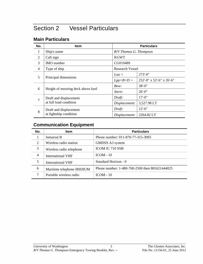
Section 2 Vessel Particulars
Main Particulars No. Item Particulars
1 Ship's name R/V Thomas G. Thompson
2 Call sign KGWT
3 IMO number CG019489
4 Type of ship Research Vessel
5 Principal dimensions Loa = 273'-0"
Lpp×B×D = 252'-8" x 52'-6" x 26'-6"
6 Height of mooring deck above keel Bow: 38'-0"
Stern: 26'-0"
7 Draft and displacement at full load condition
Draft: 17'-0"
Displacement: 3,527.98 LT
8 Draft and displacement at lightship condition
Draft: 12'-6"
Displacement: 2264.82 LT
Communication Equipment No. Item Particulars
1 Inmarsat B Phone number: 011-870-77-315-3093
2 Wireless radio station GMDSS A3 system
3 Wireless radio telephone ICOM IC 710 SSB
4 International VHF ICOM - 10
5 International VHF Standard Horizon - 0
6 Maritime telephone IRIDIUM Phone number: 1-480-768-2500 then 881621444025
7 Portable wireless radio ICOM - 10
University of Washington 4 The Glosten Associates, Inc. R/V Thomas G. Thompson Emergency Towing Booklet, Rev. – File No .11156.01, 25 June 2012
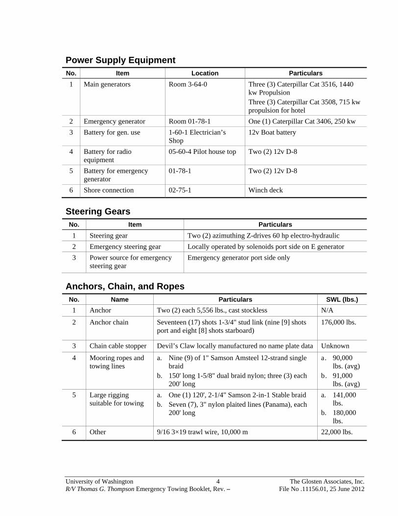
Power Supply Equipment No. Item Location Particulars
1 Main generators Room 3-64-0 Three (3) Caterpillar Cat 3516, 1440 kw Propulsion Three (3) Caterpillar Cat 3508, 715 kw propulsion for hotel
2 Emergency generator Room 01-78-1 One (1) Caterpillar Cat 3406, 250 kw
3 Battery for gen. use 1-60-1 Electrician’s Shop
12v Boat battery
4 Battery for radio equipment
05-60-4 Pilot house top Two (2) 12v D-8
5 Battery for emergency generator
01-78-1 Two (2) 12v D-8
6 Shore connection 02-75-1 Winch deck
Steering Gears No. Item Particulars
1 Steering gear Two (2) azimuthing Z-drives 60 hp electro-hydraulic
2 Emergency steering gear Locally operated by solenoids port side on E generator
3 Power source for emergency steering gear
Emergency generator port side only
Anchors, Chain, and Ropes No. Name Particulars SWL (lbs.)
1 Anchor Two (2) each 5,556 lbs., cast stockless N/A
2 Anchor chain Seventeen (17) shots 1-3/4" stud link (nine [9] shots port and eight [8] shots starboard)
176,000 lbs.
3 Chain cable stopper Devil’s Claw locally manufactured no name plate data Unknown
4 Mooring ropes and towing lines
a. Nine (9) of 1" Samson Amsteel 12-strand single braid
b. 150' long 1-5/8" dual braid nylon; three (3) each 200' long
a. 90,000 lbs. (avg)
b. 91,000 lbs. (avg)
5 Large rigging suitable for towing
a. One (1) 120', 2-1/4" Samson 2-in-1 Stable braid b. Seven (7), 3" nylon plaited lines (Panama), each
200' long
a. 141,000 lbs.
b. 180,000 lbs.
6 Other 9/16 3×19 trawl wire, 10,000 m 22,000 lbs.

University of Washington 5 The Glosten Associates, Inc. R/V Thomas G. Thompson Emergency Towing Booklet, Rev. – File No .11156.01, 25 June 2012
Deck Tools No. Item Particulars
1 Shackles and sling wire for connecting hawser
Three (3) shackles and one (1) wire sling, located in 1-94-2 (aft deck locker)
2 Sledgehammer, bar, hand hammer and knife
Located in 01-16-2 (forward deck locker) and 1-94-2 (aft deck locker)
3 Stopper rope Three (3) each located in 01-16-2 (forward deck locker) and 1-94-2 (aft deck locker)
4 Pin punch for joining shackle De-shackling kit located in 01-16-2 (forward deck locker)
5 Seizing wire or sprit pin De-shackling kit located in 01-16-2 (forward deck locker)
6 Lifeline throwing apparatus Four (4) 500' messenger line, located at 03-56-6 1 (pyro locker),
Other Facilities No. Item Particulars
Lifting Gear
1 Crane Port North American SWL 3,400 – 18,160 depending on boom angle and length
2 Crane Starboard North American SWL 3,400 – 18,160 depending on boom angle and length
Access Ladders
3 Portable rope ladder 1 Pilot ladder

University of Washington 6 The Glosten Associates, Inc. R/V Thomas G. Thompson Emergency Towing Booklet, Rev. – File No .11156.01, 25 June 2012
Foc’sle Arrangement
No. Name (deck machinery) Particulars
F-1C Anchor Windlass
Anchor Windlass Fritz Culver FCWH-8
Wildcat Unknown manual does not state pull and rated speed
Warping Head Unknown manual does not state pull and rated speed
Power Unit Electro hydraulic
No. Item (Deck Fittings) Particulars SWL (lbs)
F-2P Bollard Limited by post structure 54,700
F-2S Bollard Limited by post structure 54,700
F-3P Bollard Limited by below deck structure 41,400
F-3S Bollard Limited by below deck structure 41,400
F-4P Bollard Limited by below deck structure 32,600
F-4S Bollard Limited by below deck structure 32,600
F-5P Chock Limited by chock structure 176,000
F-5S Chock Limited by chock structure 176,000
F-6P Chock Limited by bulwark structure 28,000
F-6S Chock Limited by bulwark structure 28,000
F-7P Chock Limited by chock structure 176,000
F-7S Chock Limited by chock structure 176,000

University of Washington 7 The Glosten Associates, Inc. R/V Thomas G. Thompson Emergency Towing Booklet, Rev. – File No .11156.01, 25 June 2012
Aft Deck Arrangement
No. Item (Deck Fittings) Particulars SWL (lbs)
A-1P Bollard Bolted, limited by below deck structure 80,900
A-1S Bollard Bolted, limited by below deck structure 80,900
A-2P Bollard Bolted, limited by below deck structure 66,300
A-2S Bollard Bolted, limited by below deck structure 66,300
A-3P Chock Limited by bulwark deck sockets 21,200
A-3S Chock with horns Limited by bulwark deck sockets 21,200
A-4P Chock Limited by bulwark deck sockets 21,200
A-4S Chock with horns Limited by bulwark deck sockets 21,200
Sample of Lines and Strengths
This is a list of lines commonly available aboard most vessels.
Diameter Line Type Average Strength (lbs.)
2" Nylon 3-strand twisted 82,000 lbs.
1-1/8" Samson Amsteel 12-strand single braid 91,800 lbs.
2" Polyester 12 plait 99,9000 lbs.
2" Dual braid nylon 111,000 lbs.
2-1/4" 2-in-1 stable braid 141,000 lbs.
3" Nylon plaited lines (Panama) 180,000 lbs.

University of Washington 8 The Glosten Associates, Inc. R/V Thomas G. Thompson Emergency Towing Booklet, Rev. – File No .11156.01, 25 June 2012
Section 3 Decision Matrix for Determining Towing Arrangements
The towing pattern should be determined by the captain of the ship in consultation with the captain of the towing ship, by referring the following Decision Matrix. The ship status and the surrounding conditions (e.g. weather conditions, availability of the propulsion system and of power supply for deck machinery and imminent danger of grounding) should be taken into account considering the towing pattern.
The primary towing plan should be to tow from the bow. If it is not possible to tow from the bow due to collision, towing from the stern may be selected as an alternative.
Condition Towing Arrangement
From the Bow
From the Stern
Imminent danger such as grounding in less than 1 hour. 01, 02 06
Weather is bad when connecting the towing lines between the ship and the towing ship.
02 06, 07
No power supply for deck machinery to handle the towing lines. 01, 02, 03 06, 07
Long duration for towing; i.e. more than 1 day. 04, 05 07
Tow gear is not supplied from the towing ship. 01, 02, 03, 04, 05
06, 07
University of Washington 9 The Glosten Associates, Inc. R/V Thomas G. Thompson Emergency Towing Booklet, Rev. – File No .11156.01, 25 June 2012
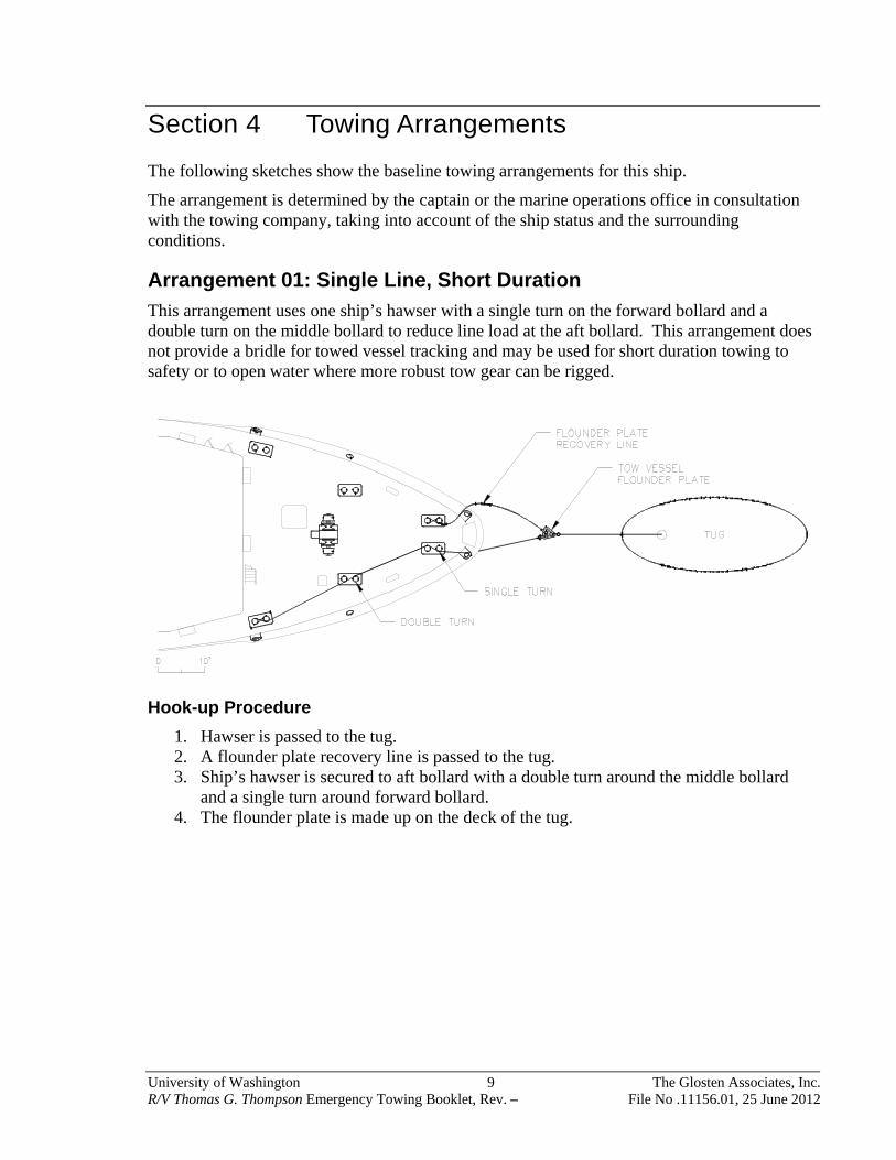
Section 4 Towing Arrangements
The following sketches show the baseline towing arrangements for this ship.
The arrangement is determined by the captain or the marine operations office in consultation with the towing company, taking into account of the ship status and the surrounding conditions.
Arrangement 01: Single Line, Short Duration
This arrangement uses one ship’s hawser with a single turn on the forward bollard and a double turn on the middle bollard to reduce line load at the aft bollard. This arrangement does not provide a bridle for towed vessel tracking and may be used for short duration towing to safety or to open water where more robust tow gear can be rigged.
Hook-up Procedure
1. Hawser is passed to the tug. 2. A flounder plate recovery line is passed to the tug. 3. Ship’s hawser is secured to aft bollard with a double turn around the middle bollard
and a single turn around forward bollard. 4. The flounder plate is made up on the deck of the tug.
University of Washington 10 The Glosten Associates, Inc. R/V Thomas G. Thompson Emergency Towing Booklet, Rev. – File No .11156.01, 25 June 2012
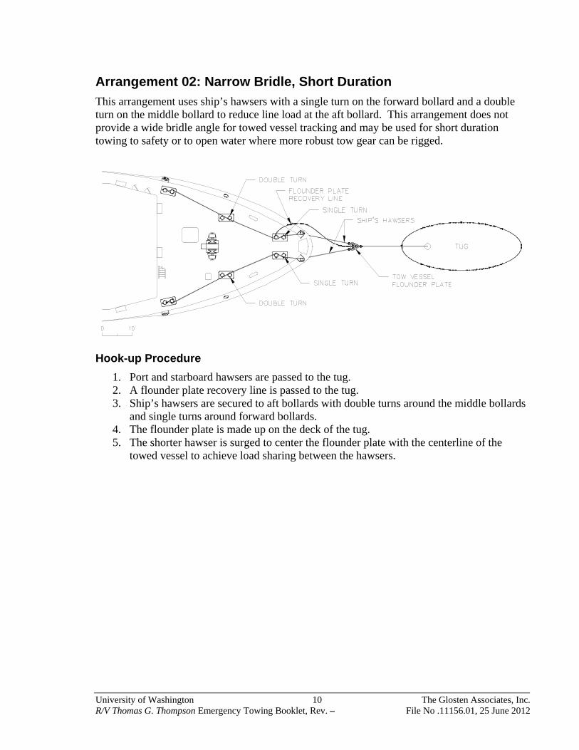
Arrangement 02: Narrow Bridle, Short Duration
This arrangement uses ship’s hawsers with a single turn on the forward bollard and a double turn on the middle bollard to reduce line load at the aft bollard. This arrangement does not provide a wide bridle angle for towed vessel tracking and may be used for short duration towing to safety or to open water where more robust tow gear can be rigged.
Hook-up Procedure
1. Port and starboard hawsers are passed to the tug. 2. A flounder plate recovery line is passed to the tug. 3. Ship’s hawsers are secured to aft bollards with double turns around the middle bollards
and single turns around forward bollards. 4. The flounder plate is made up on the deck of the tug. 5. The shorter hawser is surged to center the flounder plate with the centerline of the
towed vessel to achieve load sharing between the hawsers.
University of Washington 11 The Glosten Associates, Inc. R/V Thomas G. Thompson Emergency Towing Booklet, Rev. – File No .11156.01, 25 June 2012
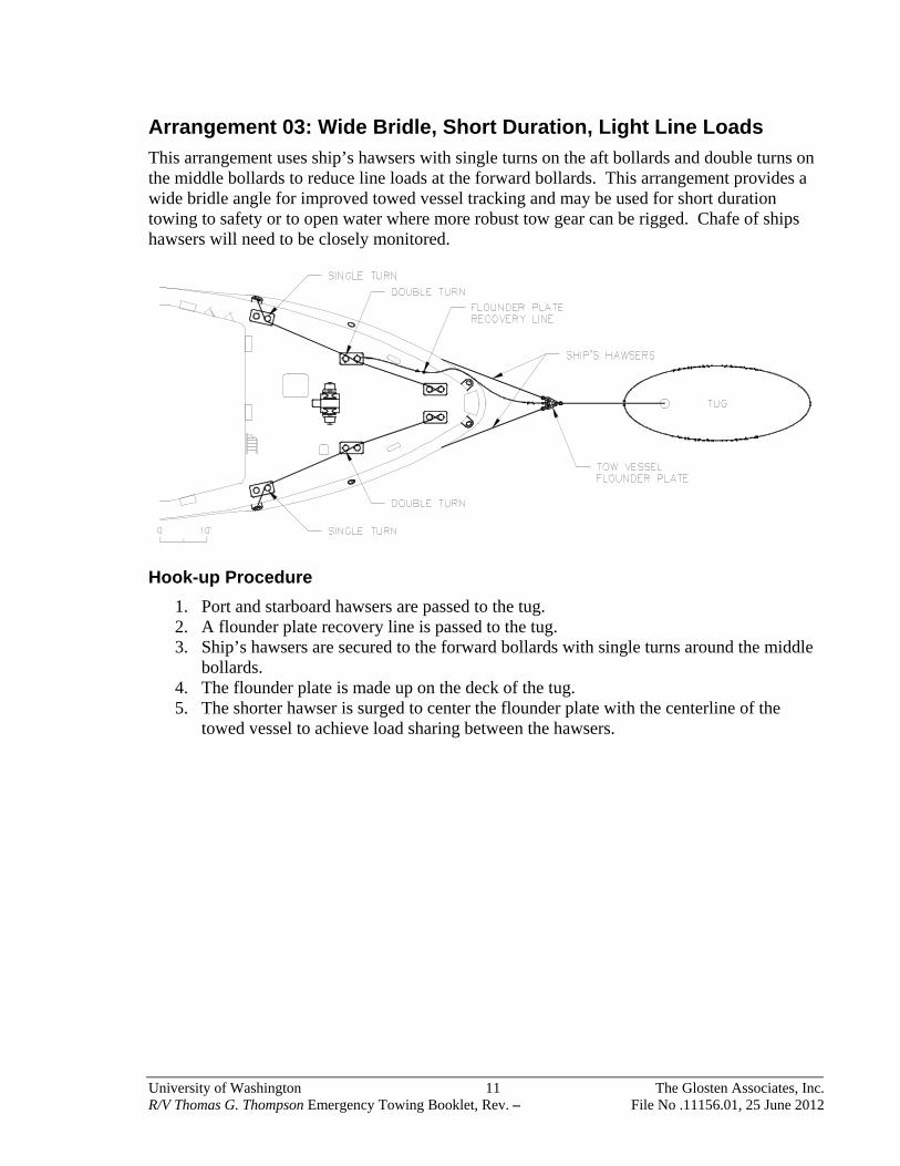
Arrangement 03: Wide Bridle, Short Duration, Light Line Loads
This arrangement uses ship’s hawsers with single turns on the aft bollards and double turns on the middle bollards to reduce line loads at the forward bollards. This arrangement provides a wide bridle angle for improved towed vessel tracking and may be used for short duration towing to safety or to open water where more robust tow gear can be rigged. Chafe of ships hawsers will need to be closely monitored.
Hook-up Procedure
1. Port and starboard hawsers are passed to the tug. 2. A flounder plate recovery line is passed to the tug. 3. Ship’s hawsers are secured to the forward bollards with single turns around the middle
bollards. 4. The flounder plate is made up on the deck of the tug. 5. The shorter hawser is surged to center the flounder plate with the centerline of the
towed vessel to achieve load sharing between the hawsers.

University of Washington 12 The Glosten Associates, Inc. R/V Thomas G. Thompson Emergency Towing Booklet, Rev. – File No .11156.01, 25 June 2012
Arrangement 04: Long Duration, Two Chains
This arrangement uses the ship’s anchor chains as tow gear. This arrangement does not provide a wide bridle angle for towed vessel tracking but may be used for long duration towing. Chain provides heavy line load surge relief and eliminates chafe on the towed vessel. Both anchors must be disconnected from anchor chains and secured in the hawsepipes for the duration of the tow.
Hook-up Procedure
1. Anchors are secured in their hawsepipes with chain stoppers, strops and binders. 2. Anchor chain is removed or cut from the anchor. 3. Ship’s hawsers are shackled to the anchor chains. 4. Port and starboard hawsers are passed to the tug. 5. A flounder plate recovery line is passed to the tug. 6. The flounder plate is made up on the deck of the tug. 7. The tug applies a light load on the tow line. 8. The anchor chains are lowered and adjusted to center the flounder plate with the
centerline of the towed vessel to achieve load sharing between the chains.

University of Washington 13 The Glosten Associates, Inc. R/V Thomas G. Thompson Emergency Towing Booklet, Rev. – File No .11156.01, 25 June 2012
Arrangement 05: Long Duration, Chain and Hawser
This arrangement uses one of the ship’s anchor chains with a hawser on the opposite bridle leg. This arrangement does not provide a wide bridle angle for towed vessel tracking but may be used for long duration towing. Chain provides heavy line load surge relief. The hawser provides some yaw control for towed vessel tracking. One anchor must be disconnected from an anchor chain and secured in its hawsepipe for the duration of the tow. The other anchor is available for regular use.
Hook-up Procedure
1. One anchor is secured in its hawsepipe with chain stoppers, strops and binders. 2. Anchor chain is removed or cut from the anchor. 3. A ship’s hawser is shackled to the anchor chain. 4. A second ship’s hawser is secured to an aft bitt with a single turn around a forward bitt. 5. Port and starboard hawsers are passed to the tug. 6. A flounder plate recovery line is passed to the tug. 7. The flounder plate is made up on the deck of the tug. 8. The tug applies a light load on the tow line. 9. The anchor chain is lowered and adjusted to center the flounder plate with the
centerline of the towed vessel to achieve load sharing between the chain and hawser.
University of Washington 14 The Glosten Associates, Inc. R/V Thomas G. Thompson Emergency Towing Booklet, Rev. – File No .11156.01, 25 June 2012
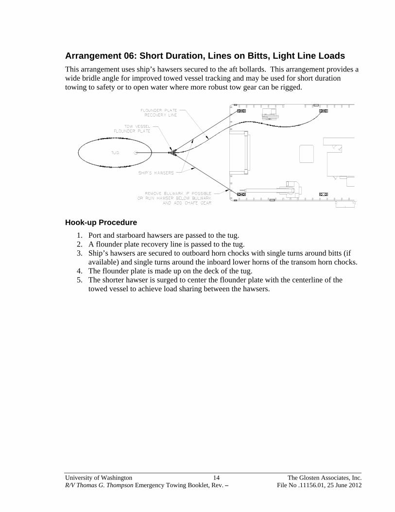
Arrangement 06: Short Duration, Lines on Bitts, Light Line Loads
This arrangement uses ship’s hawsers secured to the aft bollards. This arrangement provides a wide bridle angle for improved towed vessel tracking and may be used for short duration towing to safety or to open water where more robust tow gear can be rigged.
Hook-up Procedure
1. Port and starboard hawsers are passed to the tug. 2. A flounder plate recovery line is passed to the tug. 3. Ship’s hawsers are secured to outboard horn chocks with single turns around bitts (if
available) and single turns around the inboard lower horns of the transom horn chocks. 4. The flounder plate is made up on the deck of the tug. 5. The shorter hawser is surged to center the flounder plate with the centerline of the
towed vessel to achieve load sharing between the hawsers.

University of Washington 15 The Glosten Associates, Inc. R/V Thomas G. Thompson Emergency Towing Booklet, Rev. – File No .11156.01, 25 June 2012
Arrangement 07: Chains on A-frame
This arrangement uses ship’s hawsers with chain loops shackled around the A-frame foundation. This arrangement provides a wide bridle angle for improved towed vessel tracking and may be used for short duration towing to safety or to open water where bow tow gear can be rigged. This arrangement is suitable for high line loads.
Hook-up Procedure
1. Chains of equal length are shackled around the A-frame. 2. Ship’s hawsers of equal length are shackled to the chains. 3. Port and starboard hawsers are passed to the tug. 4. A flounder plate recovery line is passed to the tug. 5. The flounder plate is made up on the deck of the tug.

University of Washington 16 The Glosten Associates, Inc. R/V Thomas G. Thompson Emergency Towing Booklet, Rev. – File No .11156.01, 25 June 2012
Section 5 Organization
Personnel Organization
The towing operation should be conducted in accordance with the following organization chart.
Able Seaman B (handling anchor windlass mooring winch)
Towing ship Bridge
Captain
Chief Officer
(International VHF16ch)
(Onboard wireless radio)
2nd officer
Able Seaman A
Third Officer (assist)
Able Seaman C
Ordinary Seaman
Oiler B
Oiler A
Crews and Chief Officer carry portable wireless radio.
Second Engineer

University of Washington 17 The Glosten Associates, Inc. R/V Thomas G. Thompson Emergency Towing Booklet, Rev. – File No .11156.01, 25 June 2012
List of Tasks and Necessary Equipment
The following table shows the responsibilities of each crew and the necessary equipment for the towing operation. Chief Officer should have deck tools (refer to 2.7 Table of Deck Tools) prepared and provide crews with tools.
Title Duty
Necessary equipment
Life saving equipment Portable wireless radio
Chief Officer Leader on deck directing work to members
Yes Yes
Third Officer Assistant to Chief Officer Yes Yes
Second Engineer Assistant to Chief Officer Yes Yes
Able Seaman B Operator of anchor windlass mooring winches
Yes No
Able Seaman C Handling ropes Yes No
Ordinary Seaman
Handling ropes Yes No
Oiler A Handling ropes Yes No
Oiler B Handling ropes Yes No
Notes for the Towing Operation
1. During the connecting operation: a. All the crews should be well informed of the work procedures and personnel
distribution. b. The person in charge of the work (chief officer) on foc’sle or aft deck should
maintain contact the captain, and finish the work as quickly as possible. c. The person in charge of the work (chief officer) should watch the movement of
towing ship carefully. When the towing line with eye splice is strained, crews shall be evacuated to safe places.
2. During towing operation: a. It is necessary to grease up continuously in order to prevent wear of ropes in the
Panama chock when wire ropes are used as towing lines. b. Wear-out condition in chocks should be constantly checked. c. Rotation of the propeller shall be confirmed in the engine room.
3. Propeller shaft locking is installed on the Revelle. 4. An estimation of towing force vs. speed is shown in the graph on the next page. These
values are estimates based on vessel model tests combined with empirical factors to account for waves and vessel yaw during towing. As shown, significant yawing should be prevented as it will dramatically increase the towing line force.

University of Washington 18 The Glosten Associates, Inc. R/V Thomas G. Thompson Emergency Towing Booklet, Rev. – File No .11156.01, 25 June 2012
Peak loads in towing lines are largely determined by construction of the line and the surge gear used.
Towing Force, Calm Water
Towing Force, Sea State 4 and
20°yaw
0
20,000
40,000
60,000
80,000
100,000
120,000
140,000
160,000
0 2 4 6 8 10
Force (lbs)
Speed (kts)
Towing Force vs. Speed