silent knight151059 1-1 section 1 system overview this manual describes installation, operation, and...
TRANSCRIPT

Installation andOperations Manual
Central Station
Part Number 151059 Rev H
Receiver
SILENT KNIGHTModel 9500
Preliminary, 09/06

151059 i
Contents
Section 1System Overview .............................................................................................................................. 1-1
1.1 Features .................................................................................................................................................... 1-1Hardware: ...................................................................................................................................... 1-1Software: ....................................................................................................................................... 1-2
1.2 Optional Accessories ................................................................................................................................ 1-21.3 Formats Compatible with the 9500 .......................................................................................................... 1-31.4 9500 Supported SIA Digital I-III Levels ................................................................................................. 1-41.5 How to Use this Manual ........................................................................................................................... 1-51.6 Terminology ............................................................................................................................................. 1-51.7 What’s in the Box .................................................................................................................................... 1-61.8 How to Contact Silent Knight .................................................................................................................. 1-6
Section 2Agency Requirements ............................................................................................................... 2-1
2.1 Telephone Requirements .......................................................................................................................... 2-12.2 FCC Warning ........................................................................................................................................... 2-12.3 UL Requirements ..................................................................................................................................... 2-1
2.3.1 Hardware Requirements ................................................................................................................... 2-22.3.2 Operational Requirements ................................................................................................................ 2-22.3.3 Programming Requirements ............................................................................................................. 2-2
Section 3Installation ................................................................................................................................................. 3-1
3.1 Environmental Specifications .................................................................................................................. 3-13.2 Electrical Specifications ........................................................................................................................... 3-13.3 Overview .................................................................................................................................................. 3-23.4 Line Card Installation ............................................................................................................................... 3-43.5 Removing Line Cards .............................................................................................................................. 3-53.6 Telephone Line Connection ..................................................................................................................... 3-63.7 Parallel Printer Connection ...................................................................................................................... 3-7
3.7.1 Printer Cable Pin-Outs ...................................................................................................................... 3-83.7.2 Com Ports 1 & 2 ............................................................................................................................... 3-83.7.3 Programmable Remote Alert Output ................................................................................................ 3-9
3.8 AC Power Cord Connection .................................................................................................................... 3-93.8.1 Using Standard Power Cord ............................................................................................................. 3-93.8.2 Using UL Listed AC Power Connection ........................................................................................ 3-103.8.3 Switching to a 230 VAC Power Supply ......................................................................................... 3-123.8.4 How to Verify Earth Ground .......................................................................................................... 3-13
3.9 Battery Connection ................................................................................................................................ 3-143.10 Automation Computer Connection ........................................................................................................ 3-16
3.10.1 Computer Port Baud Rate Selection ............................................................................................... 3-16

Model 9500 Central Station Receiver Installation/Operation Manual
ii 151059
3.11 Master/Slave Receiver Linking .............................................................................................................. 3-173.11.1 Receiver Linking Cable .................................................................................................................. 3-173.11.2 Master/Slave Automation Configuration ........................................................................................ 3-18
3.11.2.1 Master/Slave Automation Programming ............................................................................. 3-183.11.3 Master/Slave Printer Configuration ................................................................................................ 3-19
3.11.3.1 Master/Salve Printer Programming ...................................................................................... 3-19
Section 4Operation ..................................................................................................................................................... 4-1
4.1 Touchpad Function Buttons ..................................................................................................................... 4-14.2 Displays .................................................................................................................................................... 4-3
4.2.1 LED Displays .................................................................................................................................... 4-34.2.2 LCD Status Display .......................................................................................................................... 4-3
4.2.2.1 Adjusting LCD Contrast ........................................................................................................ 4-44.2.2.2 LCD Abbreviations ................................................................................................................ 4-4
4.3 Initial System Power Up .......................................................................................................................... 4-54.4 Log On / Log Off ..................................................................................................................................... 4-5
4.4.1 Installer Profile ................................................................................................................................. 4-54.4.2 Operator Profile ................................................................................................................................ 4-54.4.3 Default User Codes ........................................................................................................................... 4-64.4.4 How to log on the system. ................................................................................................................ 4-64.4.5 How to log off the system. ................................................................................................................ 4-7
4.5 Modes of Operation ................................................................................................................................. 4-84.5.1 Normal Mode .................................................................................................................................... 4-8
4.5.1.1 Manual Operation .................................................................................................................. 4-8How to Manually Acknowledge Calls: ......................................................................................... 4-8
4.5.1.2 Automatic Operation .............................................................................................................. 4-84.5.1.3 Log Only ................................................................................................................................ 4-8
4.5.2 Program Mode .................................................................................................................................. 4-84.6 Main Menu ............................................................................................................................................... 4-9
4.6.1 How to display the Main Menu ........................................................................................................ 4-94.6.2 How to Maneuver Through Main Menu ......................................................................................... 4-104.6.3 Call History ..................................................................................................................................... 4-114.6.4 System History ................................................................................................................................ 4-114.6.5 System Info ..................................................................................................................................... 4-124.6.6 Set Time & Date ............................................................................................................................ 4-134.6.7 System Restart ................................................................................................................................ 4-144.6.8 Printer Menu ................................................................................................................................... 4-15
4.6.8.1 Print Report .......................................................................................................................... 4-17How to Print Call History ............................................................................................................ 4-17How to Print System History ...................................................................................................... 4-18How to Print System Configuration ............................................................................................ 4-19How to Print a Test Page ............................................................................................................. 4-20
4.6.8.2 Edit Event Format ................................................................................................................ 4-204.6.8.3 Configure Printer .................................................................................................................. 4-21
4.6.9 Program Menu ................................................................................................................................ 4-224.6.10 Diagnostics Menu ........................................................................................................................... 4-22
4.6.10.1 Phantom Menu ..................................................................................................................... 4-234.6.10.2 Message Que ........................................................................................................................ 4-244.6.10.3 Event Log ............................................................................................................................. 4-244.6.10.4 Format .................................................................................................................................. 4-254.6.10.5 LC Debug Mode ................................................................................................................... 4-254.6.10.6 LC Statistics ......................................................................................................................... 4-26

Contents
151059 iii
4.6.10.7 Port Status ............................................................................................................................ 4-274.6.11 PC Connection ................................................................................................................................ 4-28
4.7 Listen-In and Hang Up ........................................................................................................................... 4-294.7.1 Extend (Common) Listen-In Operation .......................................................................................... 4-294.7.2 PBX Operation ................................................................................................................................ 4-30
4.8 Testing the System ................................................................................................................................. 4-30
Section 5Programming ......................................................................................................................................... 5-1
5.1 UL 864 Programming Requirements ....................................................................................................... 5-15.2 How to Enter Program Mode ................................................................................................................... 5-1
5.2.1 Programming Fields .......................................................................................................................... 5-25.2.2 How to Maneuver Around in Program Mode ................................................................................... 5-2
5.3 Programming Choices .............................................................................................................................. 5-35.4 General Options ....................................................................................................................................... 5-3
5.4.1 Operation Mode ................................................................................................................................ 5-45.4.1.1 How to Change the Operation Mode ..................................................................................... 5-5
5.4.2 Display Options ................................................................................................................................ 5-65.4.2.1 How to Change Language Display ........................................................................................ 5-85.4.2.2 How to Change Time Format Display ................................................................................... 5-85.4.2.3 How to Change Date Format Display .................................................................................... 5-95.4.2.4 How to Set/Change Daylight Saving Time ............................................................................ 5-95.4.2.5 How to Edit ITI Options ...................................................................................................... 5-105.4.2.6 How to Edit Format (FMT) Options .................................................................................... 5-115.4.2.7 How to Set Hold Last Event ................................................................................................ 5-11
5.4.3 Communications ............................................................................................................................. 5-125.4.3.1 How to Set Up Port Function ............................................................................................... 5-145.4.3.2 How to set Com Port 1 Parameters ...................................................................................... 5-155.4.3.3 How to Set Com Port 2 Parameters ..................................................................................... 5-155.4.3.4 How to Edit Init String (Par Port) ........................................................................................ 5-16
To clear an init string: ................................................................................................................. 5-175.4.3.5 How to Set Automation Communication ............................................................................. 5-17
How to Set the Format ................................................................................................................ 5-17How Enable or Disable Hex Mode ............................................................................................. 5-18How Enable or Disable Heartbeat ............................................................................................... 5-18Set Heartbeat Time Period .......................................................................................................... 5-19Ack Time (Acknowledge Time) ................................................................................................. 5-19ITI Options (Only Visible if ITI Gen or ITIComp Formats are Chosen) ................................... 5-20Log Recs (For ITI Formats): ....................................................................................................... 5-21XID (Extended ID for ITI Panels): ............................................................................................. 5-21SupCh (Supervisory Character): ................................................................................................. 5-21NoData (No Data Character for Log Record): ............................................................................ 5-21
5.4.3.6 How to Configure the On-board Annunciator Outputs ........................................................ 5-225.4.3.7 How to Configure the Auxiliary Relay Outputs .................................................................. 5-22
5.4.4 System Options ............................................................................................................................... 5-235.4.4.1 How to Change Backup Battery Setting .............................................................................. 5-245.4.4.2 How to Set the Receiver ID Number ................................................................................... 5-245.4.4.3 How to Configure Output for Bad Data Blocks ................................................................... 5-25

Model 9500 Central Station Receiver Installation/Operation Manual
iv 151059
5.4.4.4 How to Set the Normal State of the Auxiliary Relay Contact ............................................. 5-255.4.4.5 Select the Receivers Clock Source ....................................................................................... 5-26
5.4.5 Message Queue Options ................................................................................................................. 5-265.4.5.1 Set the Message Queue Warning On Level ......................................................................... 5-275.4.5.2 Set the Message Queue Warning Off Level ......................................................................... 5-285.4.5.3 Set the Event Release Time ................................................................................................. 5-28
5.5 Line Device Menu .................................................................................................................................. 5-295.5.1 Add Device ..................................................................................................................................... 5-305.5.2 Edit Line Card ................................................................................................................................. 5-31
5.5.2.1 Edit Line Card Menu Options .............................................................................................. 5-325.5.2.2 To Enter the Edit Line Card Option ..................................................................................... 5-365.5.2.3 Handshake Sequence ............................................................................................................ 5-37
About the Handshake Sequence .................................................................................................. 5-37Change the Handshake Sequence Number .................................................................................. 5-38Change the Format Group ........................................................................................................... 5-38Change the Handshake Duration Time ....................................................................................... 5-38Change the Maximum Handshake Wait Time ............................................................................ 5-39Change the Acknowledgment Tone Duration Time ................................................................... 5-39
5.5.2.4 Pulse Format ........................................................................................................................ 5-39Select Which Format a 5-digit Pulse Format will be Received As ............................................. 5-39Select Which Format a 6-digit Pulse Format will be Received As ............................................. 5-40Select the Inter-Digit ................................................................................................................... 5-40Set for 2300 and 1400 formats that Require Acknowledges on Even Rounds ........................... 5-40Set for 3/1 and 4/1 Partially Extended Formats .......................................................................... 5-41
5.5.2.5 Line Options ......................................................................................................................... 5-41How to Set the Line Card for a Direct Line (Dedicated Line): ................................................... 5-41To Change the Number of Rings Follow These Steps: ............................................................... 5-42To Change the Ring On Time (9810 only): ................................................................................ 5-42To Change the Ring Off Time (9810 only): ................................................................................ 5-43To Change the Country Code (9815 only): ................................................................................. 5-44To Change the Ring Threshold Voltage: ..................................................................................... 5-45To Change the Phone Line Fault Detection (Sample Rate): ....................................................... 5-45
5.5.2.6 Listen-In ............................................................................................................................... 5-46To Change the Listen Mode: ....................................................................................................... 5-46To Change the PBX String: ......................................................................................................... 5-47To Change the Listen-In Timeout: .............................................................................................. 5-48To Edit the Listen-In Accounts Lists: ......................................................................................... 5-48To Add a Listen In Account ........................................................................................................ 5-49To Edit a Listen In Account ........................................................................................................ 5-49To Clear a Listen In Account ...................................................................................................... 5-49
5.5.2.7 Trap List ............................................................................................................................... 5-50To Add a Trap Account ............................................................................................................... 5-50To Edit a Trap Account ............................................................................................................... 5-50To Clear a Trap Account ............................................................................................................. 5-51
5.5.2.8 Misc. Line Opt. .................................................................................................................... 5-51To Change the Echo Suppress Setting: ....................................................................................... 5-52How to Set Caller ID ................................................................................................................... 5-52To Change the Billing Delay Setting: ......................................................................................... 5-52To Change the Hunt Group: ........................................................................................................ 5-53To Change the Ring Options (9815 only) ................................................................................... 5-53To Change Call Hang Up Settings .............................................................................................. 5-54
5.5.2.9 Ademco Auto Opt ................................................................................................................ 5-555.5.2.10 ITI Options Menu ................................................................................................................. 5-55
ITI SCode Menu: ......................................................................................................................... 5-57To Set Date/Time Flag: ............................................................................................................... 5-58To Enable or Disable ITI 300 Baud Negotiation: ....................................................................... 5-58

Contents
151059 v
Set the Type of Listen-In Used for ITI Controls: ........................................................................ 5-585.5.2.11 Line Gain Options Menu (9815 only) .................................................................................. 5-59
Changing the Transmit and Receive Gain ................................................................................... 5-59Changing the Caller ID (CID) Monitor ....................................................................................... 5-60Changing the Caller ID (CID) Gain and On Hook Gain ............................................................. 5-60Changing the Ringer Impedance ................................................................................................. 5-61
5.5.3 Copy Devices .................................................................................................................................. 5-615.5.3.1 To Program the Default Settings Into a Line Card .............................................................. 5-615.5.3.2 Copy the Programming of an Existing Line Card to Another ............................................. 5-62
5.5.4 Clear Device ................................................................................................................................... 5-63To Clear or Delete a Line Card From the Receiver: ................................................................... 5-63
5.5.5 View Device ................................................................................................................................... 5-645.5.6 Rollins ............................................................................................................................................. 5-64
5.6 User List ................................................................................................................................................. 5-655.6.1 Adding a User ................................................................................................................................. 5-665.6.2 Editing a User ................................................................................................................................. 5-675.6.3 Clearing a User From the Receiver ................................................................................................. 5-68
5.7 PC Account/Code ................................................................................................................................... 5-68
Section 6Compatible Reporting Formats ..................................................................................... 6-1
6.1 Formats By Communication Group. ........................................................................................................ 6-16.2 Format Numbers Used In Printer Output ................................................................................................. 6-36.3 Using Contact ID Format ......................................................................................................................... 6-4
Section 7Troubleshooting & Maintenance ................................................................................. 7-1
7.1 Error Messages ......................................................................................................................................... 7-17.2 Troubleshooting Process .......................................................................................................................... 7-57.3 Replacing the 9500 Fuse .......................................................................................................................... 7-67.4 Safe Mode ................................................................................................................................................ 7-77.5 Updating the Receiver Software .............................................................................................................. 7-7
Appendix AProgramming Quick Reference Chart ..................................................... A-1
Index ......................................................................................................................................................... Index-1

Model 9500 Central Station Receiver Installation/Operation Manual
vi 151059

151059 1-1
Section 1System Overview
This manual describes installation, operation, and programming of the Model 9500 Central Station Receiver (9500). The 9500 is a dual-line desktop receiver. This section lists features, optional accessories, compatible formats, and SIA options supported. This section also includes conventions used in the manual, terminology relevant to this product, and other information.
1.1 Features
Hardware:• Supports both 120 and 240 VAC installations at 60 and 50Hz operation.
• External annunciation with auxiliary Form C dry contact relay. (Programmable)
• On-board PZT alert. (Programmable.)
• 1 parallel port and 2 serial ports.
• 2 rear SBUS connectors.
• Modular configuration for easy replacement and repair.
• 4 line LCD Display with 20 characters for each line.
• On-board touchpad for manual operation and programming.
• LEDs to indicate system operations.
• One line card will communicate with all supported formats.
• Supports up to 2 line cards which operate independent of each other.
• Line card parameters are stored on the MCPU for faster removal and replacement.
• Line cards support Caller ID and Caller Name Delivery.
• Line cards are individually programmable for format priority and ring parameters.
• Line cards support direct connect phone line monitoring.
• English or Spanish language display.

Model 9500 Central Station Receiver Installation/Operation Manual
1-2 151059
Software:• Programmable display options for time and date information.
• View or print the history information by priority or by call or by event.
• Two user profiles to control user access to the receiver.
• Supports up to 40 users.
• Listen-in and trap accounts support wild card variables. Up to 20 accounts available per line card. (20 for listen-in and 20 for trap accounts.)
• Listen-in selectable for direct, hook flash, or PBX phone system.
• Programmable port configuration for automation, printer and backup support.
• 500 event history buffer.
1.2 Optional Accessories
The following accessories for the 9500 are available from Silent Knight Sales Department unless otherwise indicated. You can contact Silent Knight Sales Department by phone or by mail. The Sales Department’s toll free and local numbers are 800-446-6444 and 763-493-6435. Our mailing address is 7550 Meridian Circle, Maple Grove, MN 55369-4927.
Table 1-1: Optional Accessories for the 9500 Central Station Receiver
Item SK Model Description/Comments
Line card 9810 The line card monitors the phone line, detects ring and processes the message from the communicating panel.
Line card 9815 The line card monitors the phone line, detects ring and processes the message from the communicating panel. This is a 2nd generation line card that also supports the selection of USA CRT 21 phone service, ring options, call hang time, and line transmit and receive gain.
Backup battery 6712 See Section 3.9
A 12 VDC 7 AH battery which will provide a minimum 4 hours of backup power during an AC power loss. (See Section 2.3.2 for UL backup power requirements.)
Parallel printer SK320 The 9500 requires the SK320 parallel printer to generate a hard copy of report history.
Printer cable Not available from Silent Knight
A standard 25-pin cable used to connect the 9500 to an external parallel printer.
UL Conduit Connector Kit
9512 (See Section 3.8.2 for installation.)
Required to meet UL requirements for NFPA 72 Central Station Service.
AutomationSoftware
SK9540W Alarm center receiver software for a single user that supports up to 250 accounts. For Windows® 98 (2nd Edition).
SK9541W Alarm center receiver software for a single user that supports an unlimited number of accounts.

System Overview
151059 1-3
1.3 Formats Compatible with the 9500
The 9500 is compatible with all Silent Knight UL listed communicators.
Table 1-2 shows the formats that the 9500 can decode and the handshake frequency groups which accommodate that format (see Section 5.5 for line card programming). Each line card can decode every format listed below. Setting the handshake order only prioritizes the type of communication done by each line card. Section 6 of this manual describes the formats in greater detail.
Table 1-2: Formats compatible with the 9500
Format Name Handshake
BFSK 1400 or 2300 Hz
SK FSK, FSK 0, FSK 80 1400 or 2300 Hz
SK FSK 1, FSK 1, FSK 81 1400 or 2300 Hz
FSK II, FSK 86 1400 Hz
SK 4+2 1400 Hz
SK 3+1/3+1 Extended 1400 or 2300 Hz
Sescoa 3+1/Franklin 3+1 2300 Hz
Radionics 3+1 Checksum 1400 or 2300 Hz
4+1 Extended 1400 or 2300 Hz
FBI 4+3+1 1400 or 2300 Hz
SX-III, SX-IVA 2225 Hz
SX-IVB 2225 Hz
ITI SX-V 2225 Hz
ITI Commander 2225 Hz
ITI RF Commander, Harbor Gard 2225 Hz
ITI Commander 2000, LifeGard 2225 Hz
ITI CareTaker+, SecurityPro 4000 2225 Hz
ITI UltraGard 2225 Hz
SIA DCS 2225 Hz
SIA 2000 (pending approval) 2225 Hz
Ademco Contact ID 1400 and 2300 Hz
Ademco Super Fast 1400 and 2300 Hz
Acron Touch Tone 1400 and 2300 Hz
Ademco Express 1400 and 2300 Hz
DTMF 4+2 1400 and 2300 Hz
Westec Westec
Modem II Modem II
Modem IIe Modem IIe
Model 9500 Central Station Receiver Installation/Operation Manual
1-4 151059
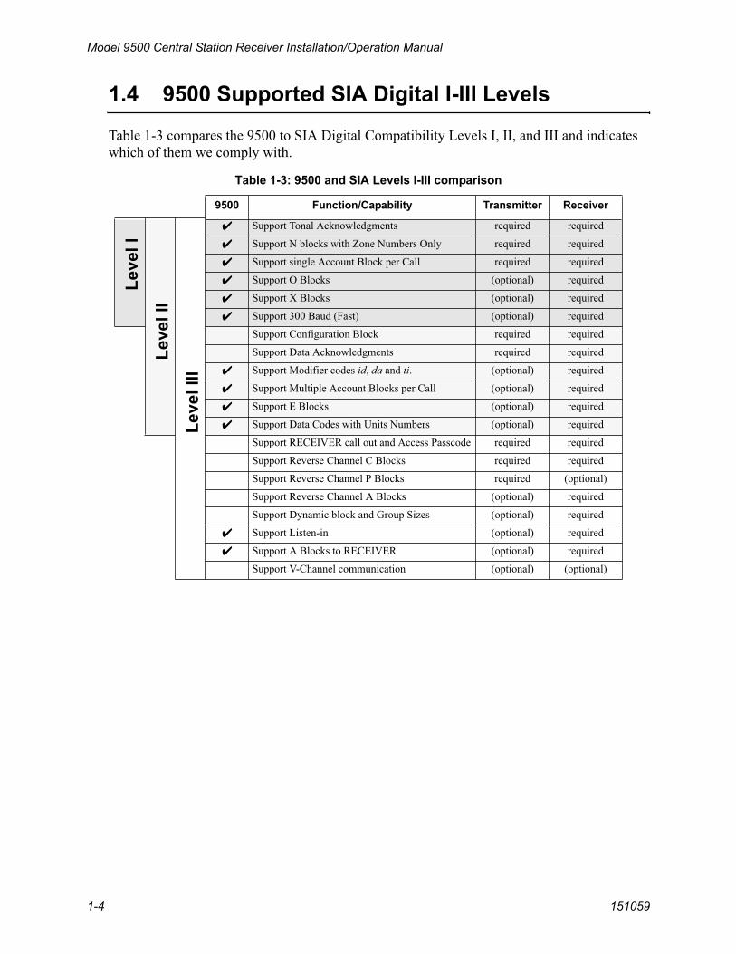
1.4 9500 Supported SIA Digital I-III Levels
Table 1-3 compares the 9500 to SIA Digital Compatibility Levels I, II, and III and indicates which of them we comply with.
Table 1-3: 9500 and SIA Levels I-III comparison
9500 Function/Capability Transmitter Receiver
Support Tonal Acknowledgments required required
Support N blocks with Zone Numbers Only required required
Support single Account Block per Call required required
Support O Blocks (optional) required
Support X Blocks (optional) required
Support 300 Baud (Fast) (optional) required
Support Configuration Block required required
Support Data Acknowledgments required required
Support Modifier codes id, da and ti. (optional) required
Support Multiple Account Blocks per Call (optional) required
Support E Blocks (optional) required
Support Data Codes with Units Numbers (optional) required
Support RECEIVER call out and Access Passcode required required
Support Reverse Channel C Blocks required required
Support Reverse Channel P Blocks required (optional)
Support Reverse Channel A Blocks (optional) required
Support Dynamic block and Group Sizes (optional) required
Support Listen-in (optional) required
Support A Blocks to RECEIVER (optional) required
Support V-Channel communication (optional) (optional)
Leve
l I
Leve
l II
Leve
l III

System Overview
151059 1-5
1.5 How to Use this Manual
This manual contains information on how to install, operate and program the 9500. Silent Knight strongly suggests that the manual be reviewed in its entirety to become familiar with procedures and parameters of the product. Once you are familiar with the product, the manual can be used as a reference document.
The manual uses the following conventions:
• A small graphic of each touchpad button is used to represent which touchpad key is to be
pressed for a given operation. For example, an up-arrow would be shown as:
• LCD display This typeface represents messages that appear on the LCD.• 2225Hz This typeface represents an editable field that appears on the LCD.• Pages of the manual are numbered by section. For example, a page numbered as “5-1” is
Page 1 of Section 5.• When this manual refers to default settings, it means programmable options set at the fac-
tory. Any programming after the receiver is powered up will change these setting.
1.6 Terminology
This section lists terminology that is specific to this product and their meaning.
Term Meaning
Communication Group Silent Knight has separated the different types of communication by handshake type. These handshake types can be assigned in a numbered order. (See Section 6 for more details.)
Listen-in Listen-in is the ability to listen in to what is happening real-time from the central station to a remote location. This can help the central station operator determine if he or she should dispatch for a particular alarm situation.
PZT PZT is an abbreviation for a piezo alert sounder.
PIN An abbreviation for Personal Identification Number. PINs are used to log in and out of the receiver.
SBUS Serial Bus interface to connect a 9500 to 9810/9815 Line cards and the LCD display.
MCPU Master Central Processing Unit.
Main Menu The main menu will be displayed as either <Installer Menu> or <Operator Menu> . However, this manual will refer to them as the main menu.
ACK Stands for acknowledgment.
NACK Stands for no acknowledgment.

Model 9500 Central Station Receiver Installation/Operation Manual
1-6 151059
1.7 What’s in the Box
This section contains a list of the parts that are shipped with the 9500 and a brief description of their intended use.
1.8 How to Contact Silent Knight
If you have a question or encounter a problem not covered in this manual, contact Silent Knight Technical Support at 800-328-0103 (or 612-493-6455). To order parts, contact Silent Knight Sales at 800-446-6444 (or 612-493-6435).
Item Quantity P/N Description
Battery/Alert Programmable Relay Wiring Harness 1 130393
Wiring harness used to connect the 9500 to a backup battery. It also provides a normally open or normally closed output for an alert sounder.
9500 Installation/Operation Manual 1 151059 A manual covering installation and operation information
related to the 9500.
Central Station Receiver 1 9500 The central station receiver assembly.
Line Card 1 9810/9815 Line card for land lines.
Strain Relief Tie Wrap 1 120101 Tie wrap used as a strain relief on the phone cord. See Figure 3-3 for location of strain relief tabs.
Telephone Cord 1 130071 A 7 foot long telephone cable with RJ-11 connectors.
Power Cable 1 119229 AC power cable used to connect the 9500 to an AC wall plug.

151059 2-1
Section 2Agency Requirements
2.1 Telephone Requirements
If requested by the telephone company, the following information must be provided before connecting this device to the phone lines:
This device may not be connected directly to coin telephones or party line services.This device cannot be adjusted or repaired in the field. In case of trouble with the device, notify the installing company or Silent Knight for an RMA and then return it to:
Silent Knight Security Systems7550 Meridian CircleMaple Grove, MN 55369-4927800-328-0103 or 763-493-6455
The telephone company may make changes in its facilities, equipment, or procedures that could affect the operation of the equipment. If this happens, the telephone company will provide advance notice to allow you to make the necessary modifications to maintain uninterrupted service.
2.2 FCC Warning
This device complies with FCC Rules Part 68.This device has been verified to comply with FCC Rules Part 15. Operation is subject to the two following conditions: (1) This device may not cause radio interference, and (2) This device must accept any interference received including interference that may cause undesired operation.
2.3 UL Requirements
Follow the procedures outlined in the sections below for listing as an NFPA 72 Central Station Service installation. The 9500 is also suitable for household and commercial burglary service. Note: Installation regulations are subject to the jurisdiction of the local authority.
A. Manufacturer: Silent Knight
B. Model Number: 9500
C. FCC Registration Number: AC6USA-31519-AL-E
D. Type of jack (to be installed by the tele-phone company):
RJ11X
Ringer equivalence: 0.1B

Model 9500 Central Station Receiver Installation/Operation Manual
2-2 151059
2.3.1 Hardware Requirements1. A second 9500 must be installed as a backup in case the primary 9500 fails. The backup
system must be able to take over within 30 seconds. (Note: This requirement does not apply to burglary-only installations.)
2. AC power must run in conduit and be attached to the 9512 conduit connector kit. See Section 3.8.2.
2.3.2 Operational Requirements1. The transmitters reporting to the 9500 must be UL Listed DACTs (digital alarm communi-
cator transmitters).
2. The central station must provide a minimum of 24 hours of backup power within 30 seconds of a AC power loss. The backup must either be in the form of a UL listed 1481 UPS or electrical generator. Listed for fire protective signaling.
3. If the 9500 is not automated, the central station operator must check for the 24 hour test signals from the communicators. (Note: This requirement does not apply to burglary-only installations.)
4. The connection between the 9500 and the UL listed computer (Computer must be suitable for use as a fire protective signaling computer.) should be according to the pin configura-tion for Com port 1 as shown in Section 3.10, Figure 3-14 and Figure 3-15, of this manual.
5. If a computer is used, the computer and its accessories must be installed in the same room as the receiver.
6. The listen-in feature is intended for burglary applications only and may not be used if the receiver will be accepting commercial fire signals.
2.3.3 Programming RequirementsIn a UL listed installation, the Model 9500 receiver must be programmed according to the following procedure:
• Do NOT use the alarm output relay in UL installations.• Each log-on code must have at least four digits.

151059 3-1
Section 3Installation
This section contains information necessary to install a 9500 Central Station Receiver.
3.1 Environmental Specifications
• Intended for indoor use in dry locations only
• Non-corrosive environment
• Temperature range: 32º to 120º F
• Humidity:10%-93% at 30°C (86°F) noncondensing
3.2 Electrical Specifications
IMPORTANT:
Do not connect power to the system until you have read these instructions carefully.
Line Voltage:120VAC ± 10% 60Hz, 100VA240VAC ± 10% 50Hz, 100VA
Fuse: 2.5A Slow Blow
Backup Battery Connection:Note: A 12 VDC battery does not provide standby time required by UL and NFPA standards. A UPS (listed for fire protective signaling use) must be utilized when standby power is required. See 5.4.4 for details on backup battery configuration.
Input 12 VDC Nominal 3 Amp Max.
Output 13.65 VDC 1 Amp charging current
Auxiliary Relay (Programmable):2.5 Amp @ 24 VAC/VDC(Inductive), 0 Hz5 Amp @ 24 VAC/VDC(Resistive), 0 Hz

Model 9500 Central Station Receiver Installation/Operation Manual
3-2 151059
3.3 Overview
The 9500 is assembled at the factory. One line card is shipped with the 9500 receiver. Follow the procedures described in Section 3.4 to install additional line cards.
Figure 3-1 Model 9500 Front View
Figure 3-2 Model 9500 Front View Without the Cover On
LEDDisplay
Touchpad
LCDDisplay
Line Card Guides
Phone Line Slots
Inserted Line Card
Phone LineConnector

Installation
151059 3-3
Figure 3-3 Model 9500 Rear View
Figure 3-4 Side View
AC PowerCord Connector
Fuse
Remote Relay
ParallelPrinter Port
SerialPorts
Phone LineSlot
Phone Line
Tie Wrap HoldersStrain Relief Connector
Flip Leg Down toRaise Up Front
Cover Screws(Two on eachside)

Model 9500 Central Station Receiver Installation/Operation Manual
3-4 151059
3.4 Line Card Installation
This section describes how to install the 9810 and 9815 line cards.
1. Remove the 9500 cover by unscrewing the four cover screws located on the both sides of the receiver. (See Figure 3-4 for the cover locations.)
2. Remove power by disconnecting the AC power cable (see Section 3.8.1 or 3.8.2 depending on the type of AC connection used) and backup battery (if used).
3. When the cover removed, you will see that there are 2 slots for line cards. The receiver recognizes each slot by number 1 and 2 (slot one is closest to the keypad and display). It is not necessary to put line cards in numbered order because the receiver continually polls each slot to see if existing line cards are functioning and if it is still in its slot. The receiver also looks to see if a new line card has been added. Figure 3-5 shows how to position each line card for installation.
Figure 3-5 Line Card Locations
4. Position the line card as shown in Figure 3-6.
Figure 3-6 Line Card Position and Components
Caution
To reduce the risk of electrical shock and damage to the receiver, follow the steps below in the order listed.
Phone LineConnector
Line CardGuides
Phone Line Slots
Installation
151059 3-5
5. Carefully slide the line card into its guides (both top and bottom) until it fits into its connector at the back of the receiver. Gently push the line card as far into the connector as you can. The line card is now in place. See Figure 3-5.
6. Connect telephone line. (See Section 3.6 for telephone line installation.)Note: Use the tie wrap (P/N 120101 provided with each line card) on the tie wrap holder to add strain relief to
the telephone lines. See Figure 3-3.
7. Return AC power and back up battery power (if used).
8. Replace the 9500's cover and screw in the cover screws to hold the cover in place. If you are simply replacing a line card with another card of the same type and are using the same format settings, your installation is now complete. If not continue to the next step.
9. Enter programming mode to select the appropriate handshake configuration. (Go to Section 5.5 for programming procedure.)
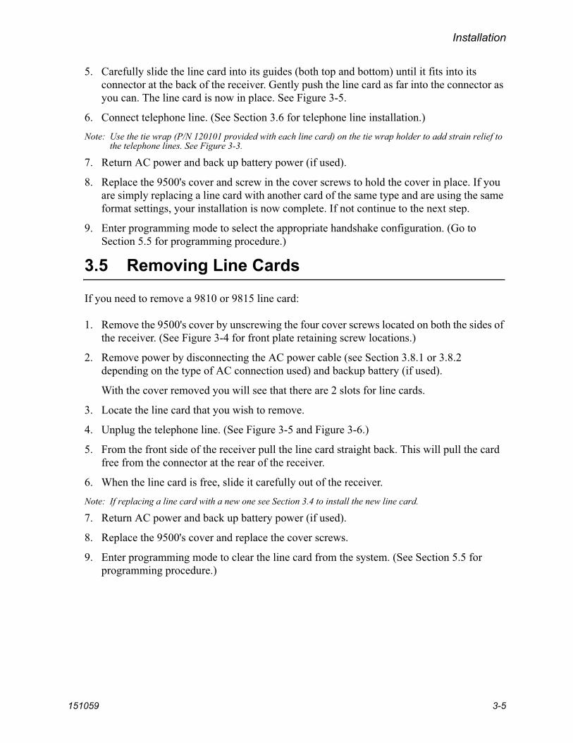
3.5 Removing Line Cards
If you need to remove a 9810 or 9815 line card:
1. Remove the 9500's cover by unscrewing the four cover screws located on both the sides of the receiver. (See Figure 3-4 for front plate retaining screw locations.)
2. Remove power by disconnecting the AC power cable (see Section 3.8.1 or 3.8.2 depending on the type of AC connection used) and backup battery (if used).
With the cover removed you will see that there are 2 slots for line cards.
3. Locate the line card that you wish to remove.
4. Unplug the telephone line. (See Figure 3-5 and Figure 3-6.)
5. From the front side of the receiver pull the line card straight back. This will pull the card free from the connector at the rear of the receiver.
6. When the line card is free, slide it carefully out of the receiver.Note: If replacing a line card with a new one see Section 3.4 to install the new line card.
7. Return AC power and back up battery power (if used).
8. Replace the 9500's cover and replace the cover screws.
9. Enter programming mode to clear the line card from the system. (See Section 5.5 for programming procedure.)

Model 9500 Central Station Receiver Installation/Operation Manual
3-6 151059
3.6 Telephone Line Connection
See Figure 3-3 for the location of the phone line inputs. Connections to the 9810 phone jacks are made with a standard 7-foot phone cord (provided with each 9810 and 9815 line card).
Use the following procedure to connect phone lines to 9810 and 9815 line cards:
1. Remove the cover of the 9500 receiver by loosening cover screws. (See Figure 3-4 for cover screws locations.)
2. From the back side of the receiver insert the telephone line through the corresponding slot for the desired line card. (See Figure 3-5 and Figure 3-6 for phone line slot locations.)
3. Gently push it all the way through to the front side of the receiver.
4. Plug the RJ-11 phone connector into the connector on the line card. (See Figure 3-5 and Figure 3-6.)
Note: Use the tie wrap (P/N 120101 provided with each line card) on the tie wrap holder to add strain relief to the telephone lines. See Figure 3-3.
5. Replace the cover of the 9500 receiver. (See Figure 3-4 for cover screws locations.)

Installation
151059 3-7
3.7 Parallel Printer Connection
The 9500 connects to the model SK320 printer for UL applications. To connect the SK320 to the 9500 follow these steps:
1. Connect the standard parallel printer cable to the parallel printer port on the back of the 9500. (See Figure 3-7.)
Figure 3-7 Parallel Printer Cable Connection to 9500
2. Connect the other end to the SK320 parallel printer port.Note: Make sure that printer power is turned off.
3. Turn the printer power “on”.

Model 9500 Central Station Receiver Installation/Operation Manual
3-8 151059
3.7.1 Printer Cable Pin-Outs25 pin printer cables are a standard items at most electronic stores, however, if you create your own cable, use the pin description in Table 3-1.
3.7.2 Com Ports 1 & 2Com ports one and two are serial communication ports that (through a null modem cable) can be used to communicate to other serial communication devices. Com port one is the only serial communications port that can be used with the automation computer (see Section 3.10). A standard null modem cable can be used to connect com port 1 or 2 to another serial device such as a printer or a PC. Figure 3-14 and Figure 3-15 shown the pin-outs for a null modem cable. See Section 5.4.3 to configure the Com Port 1 and Com Port 2.
Table 3-1: External Printer Cable Pin Description
9500 Pin # Signal Direction Description
1 Data Strobe (Low) Out A low strobe pulse to read data in the pulse width is greater than 0.5 microseconds.
2 Data Bit 1 Out These signals represent information of the first to eighth bits of parallel data. Each signal is at high level when the data is logic 1 and low when it is logic 0.
3 Data Bit 2 Out
4 Data Bit 3 Out
5 Data Bit 4 Out
6 Data Bit 5 Out
7 Data Bit 6 Out
8 Data Bit 7 Out
9 Data Bit 8 Out
10 /AckNlg In A low pulse from the printer signals the control that the printer is ready for additional data.
11 Busy In A high level indicates that the printer is busy.
12 Paper Empty In A high level indicates that the printer is out of paper.
13 Select In A low level indicates the printer is offline or in an error condition.
14 Not used - -
15 Not used - -
16 Logic ground - Logic ground for printer
17 Not used - -
18 to 25 Logic Ground - Ground return for data lines.

Installation
151059 3-9
3.7.3 Programmable Remote Alert Output1. Plug the Relay wiring harness onto the connector on the back of the 9500. (See Figure 3-
8.)Note: The remote alert output is a form C relay with a normally open or a normally closed wire.
Figure 3-8 9500 Remote Alert Output/External Backup Battery Connection
2. Connect the white wire to common.
3. Use the Yellow wire for a normally closed circuit
Or
Use the Brown wire for a normally open circuit.
3.8 AC Power Cord Connection
3.8.1 Using Standard Power Cord1. Connect the appropriate end of the power cord into its receptacle on the back of the 9500.
2. Plug the three-pronged end of the power cord into a 120 VAC 60 Hz outlet (three-prong type only). The outlet should be unswitched, so that power remains on 24 hours a day. The outlet must also be earth grounded. Follow the directions in Section 3.8.4 if you need to measure for proper earth grounding.

Model 9500 Central Station Receiver Installation/Operation Manual
3-10 151059
3.8.2 Using UL Listed AC Power ConnectionTo meet UL requirements for Central Station Service, the AC power must be run in conduit into a single gang junction box. Use UL listed Model 9512 Conduit Connector Kit to attach conduit to the receiver.
Table 3-2 lists the items contained in the 9512 Conduit Connector Kit.
Follow these steps to properly connect the AC and the 9512 connector kit:Note: It may be necessary to have a licensed electrician make the AC connections.
1. Run AC wire in conduit to the receiver.
Warning! To avoid electrical shock, make sure that AC power on the this circuit is turned off.
2. Feed AC wire through the conduit opening in the back (or the opening that best fits your conduit configuration) of the single gang electrical box.
Table 3-2: 9512 Conduit Connector Kit
Item Quantity
Single Gang Electrical Box 1
Receiver Chassis Mounting Screws 2
AC Pigtailed Power Cable 1
Installation
151059 3-11
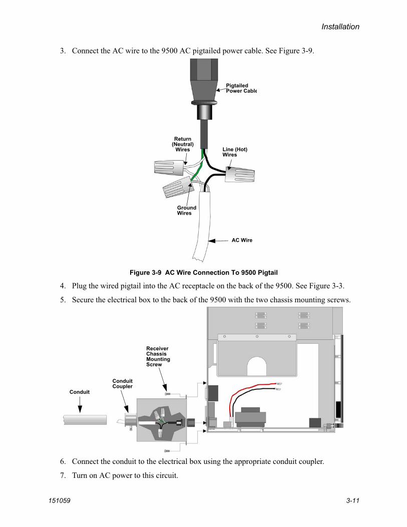
3. Connect the AC wire to the 9500 AC pigtailed power cable. See Figure 3-9.
Figure 3-9 AC Wire Connection To 9500 Pigtail
4. Plug the wired pigtail into the AC receptacle on the back of the 9500. See Figure 3-3.
5. Secure the electrical box to the back of the 9500 with the two chassis mounting screws.
6. Connect the conduit to the electrical box using the appropriate conduit coupler.
7. Turn on AC power to this circuit.
GroundWires
Line (Hot)Wires
Return(Neutral)
Wires
PigtailedPower Cable
AC Wire
Conduit
ConduitCoupler
ReceiverChassisMountingScrew

Model 9500 Central Station Receiver Installation/Operation Manual
3-12 151059
3.8.3 Switching to a 230 VAC Power Supply1. Remove the cover by unscrewing the four cover screws. (See Figure 3-4 for locations of
cover screws.)
2. Disconnect AC power cable. See Sections 3.8.1 or 3.8.2 depending on the type of AC connection used in this installation.
3. Disconnect the backup battery. (See Figure 3-13.)
4. Switch the power supply select switch to the up position. The switch will show 230VAC. (See Figure 3-10 and Figure 3-12.)
Figure 3-10 Side View of Power Supply Assembly
5. Reconnect the AC power cable.Note: Make sure to plug the AC power cable into a grounded 240VAC outlet.
6. Reconnect the back-up battery. (See Figure 3-13.)
7. Replace the cover by screwing in the four cover screws. (See Figure 3-4.)
Power SupplySelector Switch

Installation
151059 3-13
3.8.4 How to Verify Earth GroundTo verify earth ground at the AC outlet the 9500 receiver is powered from, use the following steps:
1. Measure the AC voltage between the center ground post and each side of the outlet (see A & B in Figure 3-11). You should read approximately 120 VAC (or 240VAC for 240VAC circuits) at measurement point B and nominal VAC at measurement point A.
Figure 3-11 Outlet Voltage Measurement Points
2. Measure the voltage between the two slotted holes. It should be equal to the voltage reading at measurement point B. (See Figure 3-11.)
If these voltages are not equal, the outlet does not have a proper earth ground.
3. Ground the outlet by running a wire (18 gauge or higher) to a good earth ground.
The wire should be of equal or greater diameter to the wires used to feed the outlet. It may be necessary to have a licensed electrician ground the outlet.

Model 9500 Central Station Receiver Installation/Operation Manual
3-14 151059
3.9 Battery Connection
To install the 6712 backup battery follow these steps:Note: The 6712 (12VDC 7ah battery) will provide a minimum of 4 hours of battery backup power. (See 3.8.4 for
UL requirements.)
1. Place the 6712 backup battery into the battery bucket (See Figure 3-13).
Figure 3-12 Top View of Receiver
Battery Bucket
BatteryLeads
+-
Power Supply230/115 VSelector Switch
Back of Receiver
Front of Receiver

Installation
151059 3-15
2. Connect the RED terminal to the positive (+) side of the battery.
Figure 3-13 Battery Connections
3. Connect the BLACK terminal to the negative (-) side of the battery.Note: Incorrect polarity can damage the battery and the 9500.

Model 9500 Central Station Receiver Installation/Operation Manual
3-16 151059
3.10 Automation Computer Connection
An automation computer can be connected to Com Port 1 on the 9500 receiver. Com Port 1 is a 9-pin DTE port. Refer to Automation Communication Protocols Reference Guide (PN 151393) for details on automation communication protocols. The diagrams below describe some of the cable options.
Figure 3-14 25-Pin Null Modem Cable Connection
Figure 3-15 9-Pin Null Modem Cable Connection
3.10.1 Computer Port Baud Rate SelectionThe computer port baud rate is selectable from 110 to 19200 (See Section 5 Programming).

Installation
151059 3-17
3.11 Master/Slave Receiver Linking
The SBUS connector on the receiver can be used to link up to eight receivers outputting to one automation computer and/or printer, depending on the Master/Slave configuration. The Master/Slave configuration consists of one receiver being programmed as a Master and the remaining receivers programmed as Slave receivers. The linking feature can decrease the number of serial ports required on the automation computer and/or the quantity of printers used for event logging.
There are two types of Master/Slave linking that can be used, the Master/Slave Printer configuration, and the Master/Slave Automation configuration. If a receiver is programmed as a Master Printer, then the slave receivers must be programmed as Slave Printer. And if a master receiver is programmed as Master Automation, the slave receivers must be programmed as Slave Automation receivers. See Section 5.4.4.2 for information on programming receivers for Master/Slave mode of operation.
The receivers are linked using a standard 4-wire RJ-11 phone cable.
3.11.1 Receiver Linking CableUse a 4-wire RJ-11 phone cable as shown in Figure 3-16 to connect the receivers together for receiver linking.
Figure 3-16 Receiver Linking Using an RJ-11 Cable.
Model 9500 Central Station Receiver Installation/Operation Manual
3-18 151059
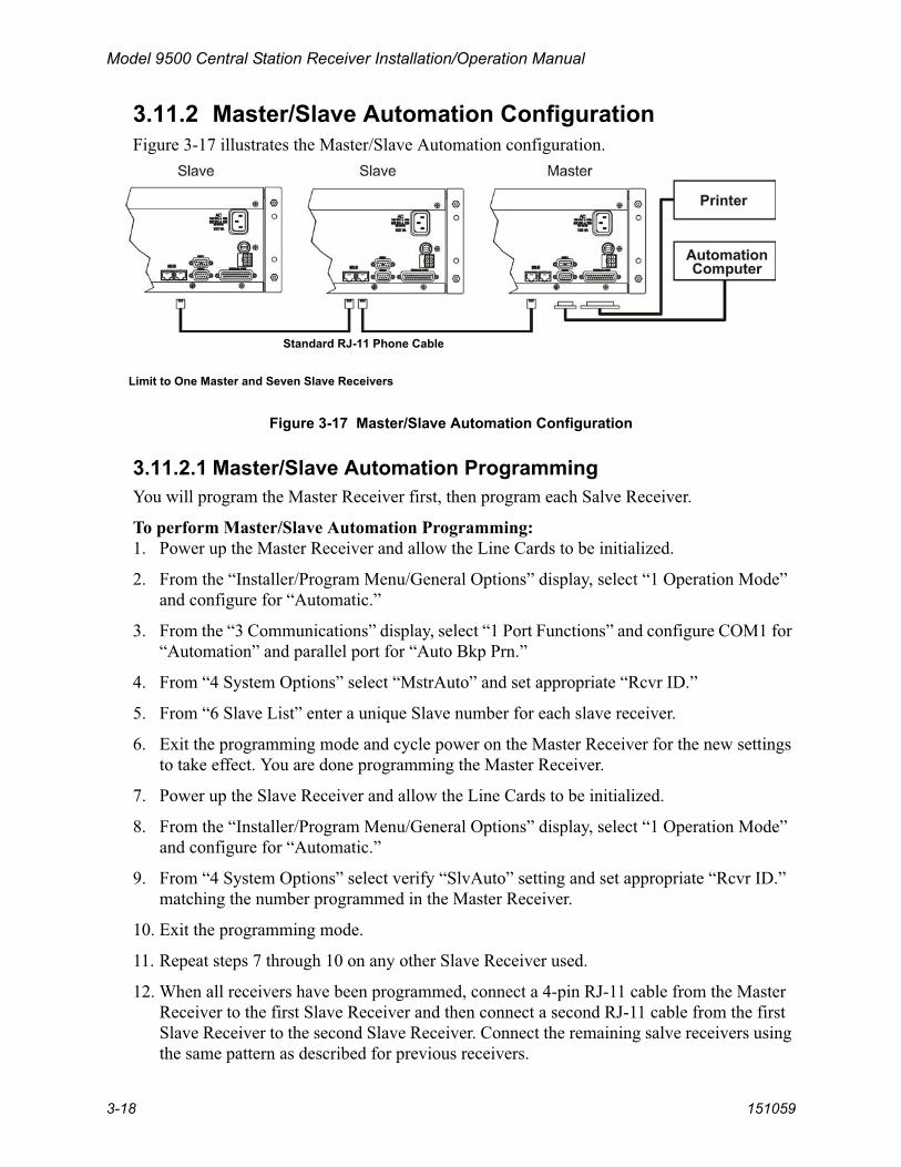
3.11.2 Master/Slave Automation ConfigurationFigure 3-17 illustrates the Master/Slave Automation configuration.
Figure 3-17 Master/Slave Automation Configuration
3.11.2.1 Master/Slave Automation ProgrammingYou will program the Master Receiver first, then program each Salve Receiver.
To perform Master/Slave Automation Programming:1. Power up the Master Receiver and allow the Line Cards to be initialized.
2. From the “Installer/Program Menu/General Options” display, select “1 Operation Mode” and configure for “Automatic.”
3. From the “3 Communications” display, select “1 Port Functions” and configure COM1 for “Automation” and parallel port for “Auto Bkp Prn.”
4. From “4 System Options” select “MstrAuto” and set appropriate “Rcvr ID.”
5. From “6 Slave List” enter a unique Slave number for each slave receiver.
6. Exit the programming mode and cycle power on the Master Receiver for the new settings to take effect. You are done programming the Master Receiver.
7. Power up the Slave Receiver and allow the Line Cards to be initialized.
8. From the “Installer/Program Menu/General Options” display, select “1 Operation Mode” and configure for “Automatic.”
9. From “4 System Options” select verify “SlvAuto” setting and set appropriate “Rcvr ID.” matching the number programmed in the Master Receiver.
10. Exit the programming mode.
11. Repeat steps 7 through 10 on any other Slave Receiver used.
12. When all receivers have been programmed, connect a 4-pin RJ-11 cable from the Master Receiver to the first Slave Receiver and then connect a second RJ-11 cable from the first Slave Receiver to the second Slave Receiver. Connect the remaining salve receivers using the same pattern as described for previous receivers.
Limit to One Master and Seven Slave Receivers
Standard RJ-11 Phone Cable
Installation
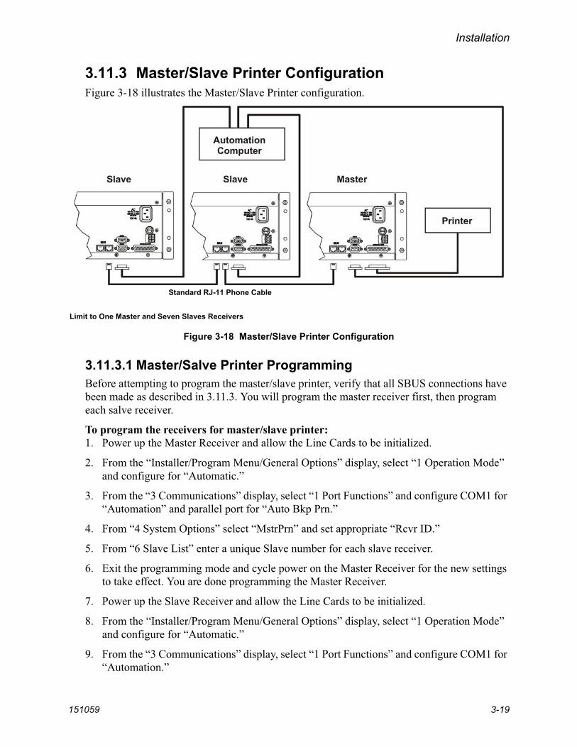
151059 3-19
3.11.3 Master/Slave Printer ConfigurationFigure 3-18 illustrates the Master/Slave Printer configuration.
Figure 3-18 Master/Slave Printer Configuration
3.11.3.1 Master/Salve Printer ProgrammingBefore attempting to program the master/slave printer, verify that all SBUS connections have been made as described in 3.11.3. You will program the master receiver first, then program each salve receiver.
To program the receivers for master/slave printer:1. Power up the Master Receiver and allow the Line Cards to be initialized.
2. From the “Installer/Program Menu/General Options” display, select “1 Operation Mode” and configure for “Automatic.”
3. From the “3 Communications” display, select “1 Port Functions” and configure COM1 for “Automation” and parallel port for “Auto Bkp Prn.”
4. From “4 System Options” select “MstrPrn” and set appropriate “Rcvr ID.”
5. From “6 Slave List” enter a unique Slave number for each slave receiver.
6. Exit the programming mode and cycle power on the Master Receiver for the new settings to take effect. You are done programming the Master Receiver.
7. Power up the Slave Receiver and allow the Line Cards to be initialized.
8. From the “Installer/Program Menu/General Options” display, select “1 Operation Mode” and configure for “Automatic.”
9. From the “3 Communications” display, select “1 Port Functions” and configure COM1 for “Automation.”
Limit to One Master and Seven Slaves Receivers
Standard RJ-11 Phone Cable

Model 9500 Central Station Receiver Installation/Operation Manual
3-20 151059
10. From “4 System Options” select verify “SlvPrn” setting and set appropriate “Rcvr ID.” matching the number programmed in the Master Receiver.
11. Exit the programming mode.
12. Repeat steps 7 through 11 for each additional Slave Receiver used.

151059 4-1
Section 4Operation
This section covers information on how to operate the 9500 Central Station Receiver.
4.1 Touchpad Function Buttons
The front panel of the 9500 has a touchpad, an LCD display, and LED indicators. (See Figure 4-1.)
Figure 4-1 Model 9500 Front Panel
The touchpad on the 9500 Receiver is used in all operating modes (normal and programming mode).
Touchpad
LED
LCD Display
Keys
Indicators

Model 9500 Central Station Receiver Installation/Operation Manual
4-2 151059
Table 4-1 displays each touchpad key and describes its function in normal and programming mode.
Table 4-1: Functions of Touchpad Buttons
Key NameOperating Modes
Normal Programming
Up Arrow Display previous event. Go back to previous choice or character.
Down Arrow Display next event. Move to next choice or character.
Left Arrow Display previous call. Exit the current menu. Move to previous programming field.
Right Arrow Display next call. Select menu item indicated by equal sign (see Figure 4-4). Move to next programming field.
Enter/Menu Button Bring up Main Menu. Select menu item indicated by equal sign (see Figure 4-4). Enter chosen parameter.
Acknowledge Button Manually Acknowledge a call or event. (Used only if receiver is in manual mode.)
Used in log mode to acknowledge and silence system troubles.
Log Button Pressed to log on or off the system. Pressed to view system status messages.
N/A
- Digit Keys Used to enter numeric
inputs.Numeric input, option selection.
Star or Home Key Will return display to the oldest unacknowledged event.
Enters a * Character when programming in an “Edit” field. See Table 5-1 for Types of Programming Fields descriptions.
0 or Hangup key In manual mode the 0/hangup key is used to hangup line card when the listen feature was activated, or to end a runaway call from a panel.
Used to enter numeric inputs.
Pound Key or Listen Key
In manual mode this key is used to initiate the listen in feature.
Enters a # Character when programming in an “Edit” field. See Table 5-1 for Types of Programming Fields descriptions.

Operation
151059 4-3
4.2 Displays
This section describes the two types of displays that the 9500 uses.
4.2.1 LED Displays
4.2.2 LCD Status DisplayThe status display is a 4-line 20 character (each line) back-lit LCD that shows the various alarm and function messages. It functions in all modes of operation (normal and programming mode). As the 9500 acknowledges calls and messages, it updates the calls on the LCD and silences the alert tone.
Figure 4-2 LCD Display
Table 4-2: LED Description
LEDMeaning
On Off Flashing
Touchpad LEDs
AC Power AC power is on. No AC or DC power to the Receiver
No AC power and the system is operating on the backup battery.
System Fault A fault condition exists that has been acknowledged but not cleared.
The system is operating normally.
A fault condition exists that has not been acknowledged.
Operator Logged In An operator is logged on. No operator is logged on.
Call Pending The acknowledge key was pressed at least once, but not all the events in a call were acknowledged.
No calls pending or all calls have been acknowledged.
Calls pending.
Line Card LEDs
Fault (Red) N/A The line card is operating normally.
Trouble or fault condition exists.
Active (Green) The line card is in active communication.
No Activity. Indicates the line is ringing.
Listen (Amber) Comes on when operator acknowledges the listen-in call.
No listen-in occurring. N/A
“Man: Active” is diplayedif not using automation
software

Model 9500 Central Station Receiver Installation/Operation Manual
4-4 151059
4.2.2.1 Adjusting LCD ContrastThe LCD is factory set at the highest contrast level and for most installations will not need to be adjusted. Use these steps to change the LCD contrast if the brightness of the room or the location in which the receiver is located should require a contrast change:
1. Press and hold both the up arrow and the left arrow keys at the same time. (See Figure 4-3.)
Figure 4-3 Contrast Adjustment
2. Release the up and left arrow keys when you reach the desired contrast level.
4.2.2.2 LCD AbbreviationsMany of the words used on the LCD are abbreviated to accommodate 20 characters per line. Table 4-3 compares the event that is reported to how it is output to the LCD and printer.
Table 4-3: LCD and Printer Abbreviations
Event LCD Printer Event LCD Printer
Alarm Alrm Alarm Test Test Test
Trouble Trbl Trouble Listen-in Lstn Listen
Restore Rstr Restore System Sytm System
Supervisory Sprv Superv Access Accs Access
Opening Open Opening Report Rprt Report
Closing Clos Close Cancel Cncl Cancel
Remote Rmot Remote Zone Number Z# Zone
Disable Dsbl Disable Door Number D# Door
Bypass Byps Bypass User Number Us# User
Unbypass Ubyp Unbypass Area Number A# Area

Operation
151059 4-5
4.3 Initial System Power Up
Apply power to the 9500 by plugging in the AC power cable and connecting the backup battery (if used). When the 9500 powers up, you will see the LCD display a sequence of screens. Power up will take several minutes. When power up is complete and everything is operating normally, the LCD display looks like Figure 4-2. The 9500 defaults to manual operation on power up. To select automatic operation see Section 5.4.1.1.Note: You must reprogram the time and date whenever the main power is removed.
4.4 Log On / Log Off
Persons operating the 9500 must log on and off the system. This is a way of keeping track of whom is operating the system at any given time.You can program a total of 40 codes. Each code will be assigned to one of two user profiles (Installer profile or Operator profile). (See Section 4.4.3 for default user codes.)
4.4.1 Installer ProfileThe Installer profile will have access to all options on the main menu (see Table 4-4 for “Main Menu” options).
4.4.2 Operator ProfileThe Operator profile has access to fewer main menu options than the Installer profile (see Table 4-4). These options allow the operator to perform basic operation of the 9500. Both profiles can acknowledge all calls and events. See Section 4.6 for detailed information on the main menu options.Note: You must have at least one Installer Profile Code programmed in the system at all times.
Table 4-4: Main Menu Option Items by Profile
InstallerProfile
OperatorProfile Menu Options
Call History
System History
System Info
Set Time & Date
System Restart
Printer Menu
Program Menu
Diagnostics

Model 9500 Central Station Receiver Installation/Operation Manual
4-6 151059
4.4.3 Default User CodesAt initial power up, the system provides two default user codes. User code 1 defaults with an Installer profile and user code 2 defaults with an Operator profile. Table 4-5 shows the default codes and their profiles.
* User code 1 can be changed but not deleted. User code 1’s profile will always remain as “installer”.
4.4.4 How to log on the system.Follows these steps to properly log on to the system:
1. Press the button.
The LCD will display Enter Log In Code:[ ]
2. Enter your PIN code. (See Table 4-5 for default codes.)Note: This screen will time out after 15 seconds.
3. Press the button.
If the correct PIN is entered the LCD will display Installer # XXUser Name.
The “Operator Logged In” LED will also turn on.
If an invalid code is entered the LCD will display Access code not verified.Note: If the previous user has not logged off, a new user can still log on by entering a PIN code. This will
automatically log off the previous user and log in the new user.
Table 4-5: Default User Codes
User Number Default Code (PIN) Default Profile
1* 9500 Installer
2 1111 Operator

Operation
151059 4-7
4.4.5 How to log off the system.Follows these steps to properly log off the system:
1. Press the button.
The LCD will display #nn User NameLog Out[ ]
Note: This screen will time out after 15 seconds.
2. Enter your PIN code. (See Table 4-5 for default codes.)
3. Press the button.
If the correct PIN is entered the LCD will display User Name Logged out. The “Oper-ator Logged In” LED will also turn off.
If an invalid code is entered the LCD will display Access code not verified.

Model 9500 Central Station Receiver Installation/Operation Manual
4-8 151059
4.5 Modes of Operation
This section describes the different modes of operation for the 9500 Receiver (normal mode and programming mode) and the options available in them.
4.5.1 Normal ModeNormal mode consists of three options, one if the receiver is intended to be used with a automation system, one for manual operation, and one to just log the events without manual acknowledgments or automation communication.
4.5.1.1 Manual OperationRequires a manual acknowledgment of each call or event from an operator.
How to Manually Acknowledge Calls:When a the call pending LED is flashing and the on-board annunciator is beeping:
1. Press the button to acknowledge the call.
2. Repeat step 1 until all calls are acknowledged and the display shows No More Data.
4.5.1.2 Automatic OperationEvent information is sent directly to the automation computer.Note: If the automation system fails, the receiver will automatically switch to manual mode in less than 30
seconds. The switching time is twice the value set in Ack Timeout (See Table 5-5). The receiver will return to automatic mode after communication to the automation computer is restored.
4.5.1.3 Log OnlyLog only mode will log event data without manual acknowledgments or communications with the automation computer. All event information is intended for printer output.Note: On initial power-up the receiver will default in manual operation. The receiver can be set to automatic or
log only operation in program mode (see Section 5.4.1).
4.5.2 Program ModeIn program mode all general, line card, and user profile options can be changed. See Section 5 Programming for more detailed information on programming the receiver or refer to the Quick Chart (Appendix A) for programming overview.

Operation
151059 4-9
4.6 Main Menu
This section gives detailed information about the items available in the Installer/operator menu options, which this manual will refer to as the main menu. The menu items available to each logged on user is dependent on the profile assigned to that user (see Table 4-4 for menu items for each profile). The user profile is assigned to each user through programming (see Section 5.6 for programming user profiles).
4.6.1 How to display the Main MenuOnce a user has logged on to the system (see Section 4.4.4), follow these steps to view the main menu options:
1. Press .
The LCD display will show the main menu options.
Figure 4-4 Main Menu Display
Note: The main menu display will remain visible for 15 minutes of idle time after which it will revert back to the manual or automatic display window. See Figure 4-2.
2. Choose the desired menu item. (See Figure 4-5.)

Model 9500 Central Station Receiver Installation/Operation Manual
4-10 151059
4.6.2 How to Maneuver Through Main MenuFigure 4-5 indicates which keys on the touchpad are used to maneuver through the Main Menu.
Figure 4-5 Main Menu Controls

Operation
151059 4-11
4.6.3 Call HistoryCall history displays the calls that are in the history buffer.
Figure 4-6 View of a Call History Screen
Note: The Letter preceding the line card number may appear as a “G” if the line card the call came in on is programmed for a hunt group. See “Misc. Line Opt.” in Section 5.5.2.8.
To display a specific event enter the reference number then press . Press the to
go to most recent call. See Table 4-3 for display abbreviations.
4.6.4 System HistorySystem history displays any events that are stored in the history buffer. System events are any events related to the receiver operation such as line card faults, low backup battery, AC power loss, log in, log out, system program change, communication failure to a printer or automation system, etc.
Figure 4-7 System History Display Sequence
Note: Up arrow moves back to the previous event that occurred.
To display a specific event enter the event number (see Figure 4-7) then press .
Press to go to most recent call.
Line Card No. Account Number
Month &Day Time
Number and orderof events for thisreport
Star indicates thatthe call was acknowledged
Reason for Call
Zone Number
Event ReferenceNo. (0001-9999) (Up to Eight Digits)
View after2 pressed
Up arrowdisplays previousevent
Event Number

Model 9500 Central Station Receiver Installation/Operation Manual
4-12 151059
4.6.5 System InfoSystem Info is a non-editable screen that displays the model number, the software revision, software date code, receiver ID number. If a down arrow is pressed, the display will show the line card firmware information, which includes the model number, the software revision, the software date code, and letter revision.
Figure 4-8 System Information Display
Model Number
Date Code
Version Number
Letter Rev.FirmwarePart Number

Operation
151059 4-13
4.6.6 Set Time & DateIf Set Time & Date is selected, the operator can change the time and date currently displayed on the receiver. (See Figure 4-9 for setting time and date procedure.)
Figure 4-9 Setting Time and Date Program Sequence

Model 9500 Central Station Receiver Installation/Operation Manual
4-14 151059
4.6.7 System RestartSystem restart allows the operator or installer to restart the receiver. An installer has the option to set the receiver back to factory default settings, while an operator can only restart the receiver. Note: The time and date set in the receiver will be saved. However, all of the call history will be lost
Figure 4-10 System Restart Display
Follow These Steps to restart the receiver:Note: All messages must be acknowledged before a system restart procedure can be performed. If all messages
are not acknowledged, cycle the receiver’s power to restart the system. If the power is cycled all unacknowledged messages will be lost.
1. Log on to the receiver (see Section 4.4.4 for log on procedure).
2. Press to view the main menu items.
3. Press for System Restart.
The display reads Do you wish toshutdown & restartsystem?No
4. Press or to toggle No to Yes.
5. Press . Users with an operator profile are done at this point.
The display reads Do you wish to setto factory defaultsettings?No
Note: This display will only appear if the logged on User has an Installer Profile (see section 4.4.1).
6. Press or to toggle between No and Yes.
Note: If you choose Yes all line card and user custom programming will be lost.

Operation
151059 4-15
4.6.8 Printer MenuIn the print menu you can print customized reports by the type of alarm (as defined by UL 864, Section 72.15F), edit the desired print output, configure output for your printer.
Figure 4-11 Print Menu Items
Table 4-6: Printer Menu Choices
Printer Menu Choice 1 Choice 2 Comments
Print Report
Call History
Priority 1(Life safety signals-Fire, Duress)
Y Indicates that this item will print on this report.N Indicates that this item will not print on this report.The call History print will execute once you exit from “Choice 2”.Note: Choice 2 settings are not retained in flash
memory and have to be chosen for each call history printing.
Priority 2(Property safety signals-Burg.)
Priority 3(Supervisory signals)
Priority 4(Trouble signals)
Priority 5(All other signals)
System History This option prints all the system events in the event history buffer.
System Config
Print All Print all of the receiver and line card data.
Program Data Print just the systems programmed data.
Line Card # Print line card configurations per line card.
Test Page Print a test page.

Model 9500 Central Station Receiver Installation/Operation Manual
4-16 151059
Edit Evnt Format
Date/Time Y or N Y = date and time will print for each report message to the printer.N = Date and time will not print for each report message to the printer.
Format Type Y or N Y = The reporting format type of the calling control panel will print for each report message to the printer.
N = The reporting format type of the calling control panel will not print for each report message to the printer.
Note: The Format Type will be listed as a number, which represents the format used for that communication.
Ref Number Y or N Y = The reference number will print for each report message to the printer.N = the reference number will not print for each report message to the printer. See Figure 4-6
Call Sep Y or N Y = Print a dashed-line between each message report to the printer.N = Do not print a dashed-line between each message report to the printer.
Device Num Y or N Y = Print the device number of the reporting message to the printer.
N = Do not print the device number of the reporting message to the printer.
Prt Condensed Y or N Y = Event information printed in an abbreviated format, reducing each event to one printed line. Use to save paper.N = Default. Event information printed in standard, longer format. Each event uses three lines when printed.
Config Printer
LineTerminator
CR or CRLF CR = Carriage return. CRLF = Carriage return and line feed.
Offline Time
0 - 60 seconds How long the receiver waits before giving a trouble indication after communication is lost with the printer. The default setting is 2 seconds. (30 second maximum for UL applications.)
Switch Delay Time
0 - 60 seconds The duration the receiver waits before switching to the backup printer after communication is lost with the primary printer. The default setting is 20 seconds.
Table 4-6: Printer Menu Choices
Printer Menu Choice 1 Choice 2 Comments
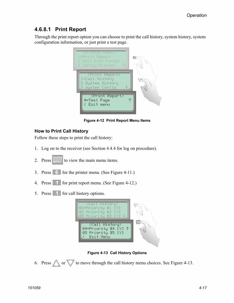
Operation
151059 4-17
4.6.8.1 Print ReportThrough the print report option you can choose to print the call history, system history, system configuration information, or just print a test page.
Figure 4-12 Print Report Menu Items
How to Print Call HistoryFollow these steps to print the call history:
1. Log on to the receiver (see Section 4.4.4 for log on procedure).
2. Press to view the main menu items.
3. Press for the printer menu. (See Figure 4-11.)
4. Press for print report menu. (See Figure 4-12.)
5. Press for call history options.
Figure 4-13 Call History Options
6. Press or to move through the call history menu choices. See Figure 4-13.
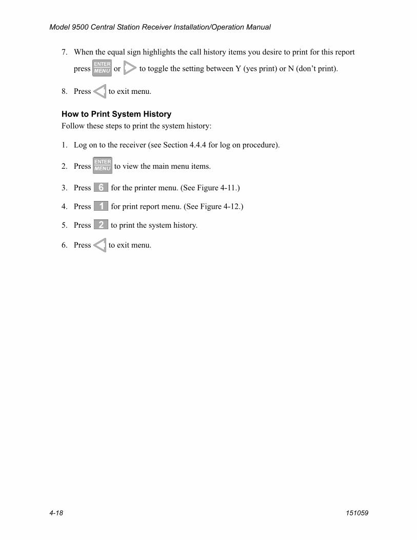
Model 9500 Central Station Receiver Installation/Operation Manual
4-18 151059
7. When the equal sign highlights the call history items you desire to print for this report
press or to toggle the setting between Y (yes print) or N (don’t print).
8. Press to exit menu.
How to Print System HistoryFollow these steps to print the system history:
1. Log on to the receiver (see Section 4.4.4 for log on procedure).
2. Press to view the main menu items.
3. Press for the printer menu. (See Figure 4-11.)
4. Press for print report menu. (See Figure 4-12.)
5. Press to print the system history.
6. Press to exit menu.

Operation
151059 4-19
How to Print System ConfigurationFollow these steps to print the system configuration:
1. Log on to the receiver (see Section 4.4.4 for log on procedure).
2. Press to view the main menu items.
3. Press for the printer menu. (See Figure 4-11.)
4. Press for print report menu. (See Figure 4-12.)
5. Press to view system configuration options. See Figure 4-14.
Figure 4-14 System Configuration Print Items
6. Press or to move through the system configuration print choices.
7. When the equal sign highlights an option press or to toggle the setting between Y (yes print) or N (don’t print).
8. Press to print the data and exit menu.
Note: These choices are not saved to flash memory and will have to be chosen each time that print system configuration is entered.

Model 9500 Central Station Receiver Installation/Operation Manual
4-20 151059
How to Print a Test PageFollow these steps to print a test page:
1. Log on to the receiver (see Section 4.4.4 for log on procedure).
2. Press to view the main menu items.
3. Press for the printer menu. (See Figure 4-11.)
4. Press for print report menu. (See Figure 4-12.)
5. Press to print a test page.
6. Press to exit menu.
4.6.8.2 Edit Event FormatEdit event format allows you to configure what information will print on reports to the receiver.
Follow these steps to configure the report format:
1. Log on to the receiver (see Section 4.4.4 for log on procedure).
2. Press to view the main menu items.
3. Press for the printer menu. (See Figure 4-11.)
4. Press for event format menu items. (See Figure 4-15.)
Figure 4-15 Event Format Menu Items

Operation
151059 4-21
5. Press or to move through the event format choices. (See Table 4-6 for choice definitions)
6. When the equal sign highlights an option press or to toggle between Y (yes print) or N (don’t print).
Note: These settings are saved to flash memory.
7. Press to exit menu.
4.6.8.3 Configure PrinterDepending on the printer you are using it may require that this be set to either carriage return or carriage return with a line feed.
Follow these steps to configure the printer:
1. Log on to the receiver (see Section 4.4.4 for log on procedure).
2. Press to view the main menu items.
3. Press for the printer menu. (See Figure 4-11.)
4. Press for configure printer menu items.
The display will be flashing on the line terminator field.
5. Press or to toggle between CR or CRLF. (See Table 4-6.)
6. When the desired setting is flashing press .
The display will now flash on the offline time field.
7. Enter the desired time (from 01-99 seconds), 30 second maximum in UL applications.
8. Press .
The display will now flash on the switch delay time field.
9. Enter the desired time (from 01-99 seconds).
10. Press .
11. Press to exit menu.
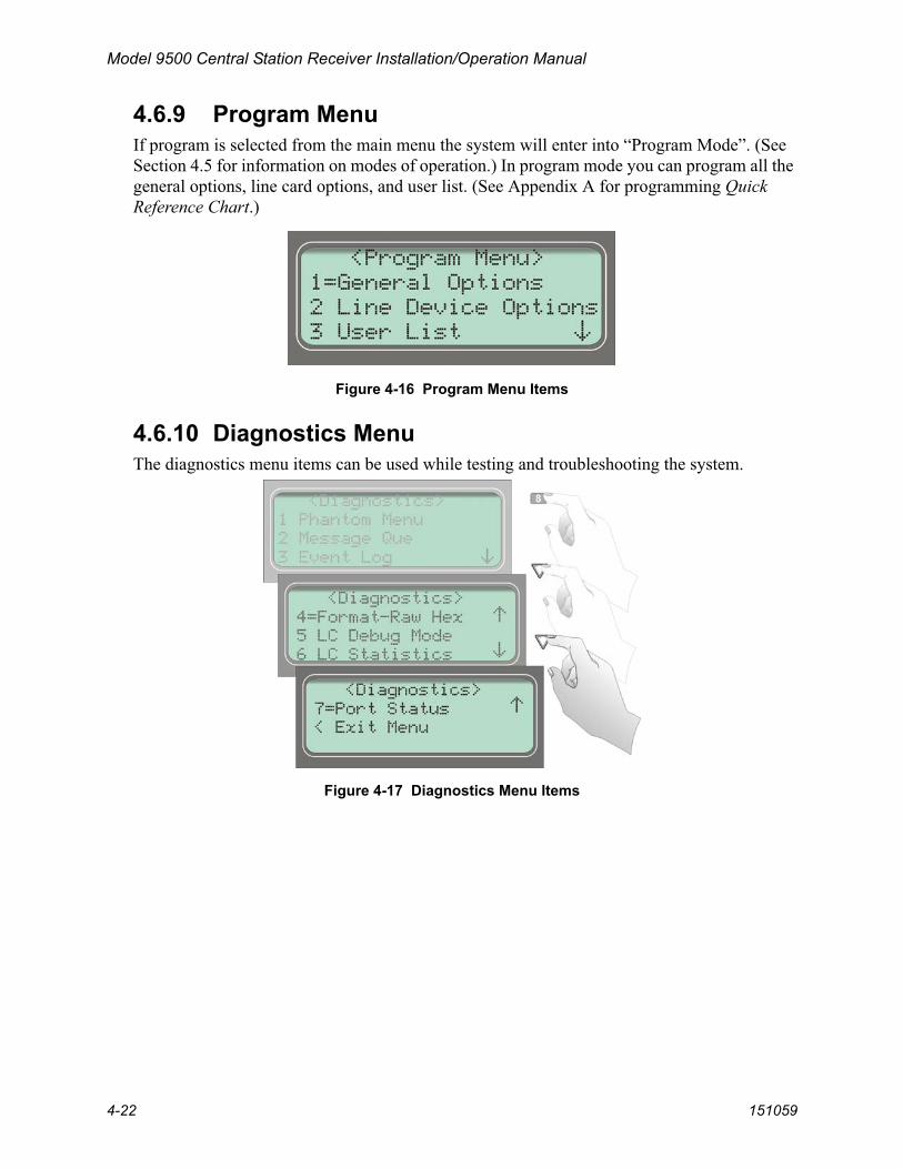
Model 9500 Central Station Receiver Installation/Operation Manual
4-22 151059
4.6.9 Program MenuIf program is selected from the main menu the system will enter into “Program Mode”. (See Section 4.5 for information on modes of operation.) In program mode you can program all the general options, line card options, and user list. (See Appendix A for programming QuickReference Chart.)
Figure 4-16 Program Menu Items
4.6.10 Diagnostics MenuThe diagnostics menu items can be used while testing and troubleshooting the system.
Figure 4-17 Diagnostics Menu Items

Operation
151059 4-23
4.6.10.1 Phantom MenuThe phantom menu contains list of various communication format phantom signals (see Table 4-8) that can be used to test the receiver or automation software configurations. For example, you set a line card parameters for a particular communications format and would know like to verify that this new configuration will communicate with other communication formats, you can send phantom signals in the formats you wish to test that line card with.
Table 4-7: Phantom Signals Formats List
Choice Format
01 DCS DCS
02 CID Contact ID
03 ITI ITI format
04 BFSK BFSK
05 3/1 3/1 format
06 3/2 3/1 format w/checksum
07 4/1 4/1 format
08 4/2 4/2 format
09 FSK0 FSK0
10 FSK1 FSK1
11 FSK2 FSK2
12 SIA D1 SIA D1
13 ADM42 Cksum Ademco 4/2 format w/checksum
14 SIA D1 Cksum SIA D1 w/checksum
15 ACRON TOUCH TONE Acron Touch Tone
16 ADM41 Cksum Ademco 4/1 format w/checksum
17 FBI 4+3+1 FBI 4+3+1
18 Modem IIE Modem IIe format
19 SIA-2000 SIA 2000 format

Model 9500 Central Station Receiver Installation/Operation Manual
4-24 151059
4.6.10.2 Message QueMessage Que gives a visual indication of how full is the message queue. It does this with both a percentage indication and a bar graph (made of *’s). Each * is approximately 5%.
Figure 4-18 Message Queue Level
4.6.10.3 Event LogEvent Log allows you to print out a certain range of reference numbers to the port designated to diagnostics. This can be used as a troubleshooting tool while correlating alarm messages from the receiver to the automation computer.
Figure 4-19 Event Log Display
For example, if the automation computer indicated a report that you are not familiar with, you would enter the reference number for that report in the event log and the raw data would be output to the diagnostic port. From the raw data you could determine what the signal was and make an adjustment to the automation computer for future signals like that one.
Enter the reference number you wish to start at here.
Enter the range of event here.
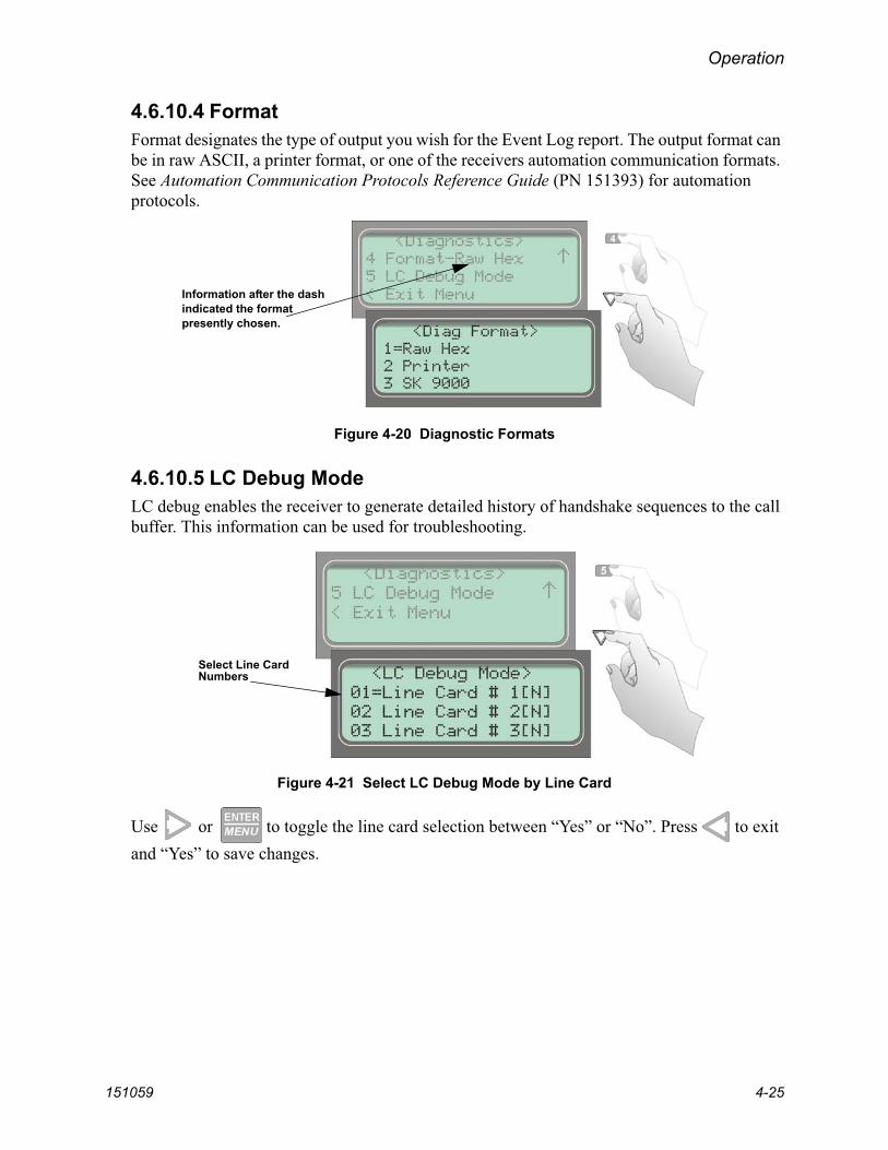
Operation
151059 4-25
4.6.10.4 FormatFormat designates the type of output you wish for the Event Log report. The output format can be in raw ASCII, a printer format, or one of the receivers automation communication formats. See Automation Communication Protocols Reference Guide (PN 151393) for automation protocols.
Figure 4-20 Diagnostic Formats
4.6.10.5 LC Debug ModeLC debug enables the receiver to generate detailed history of handshake sequences to the call buffer. This information can be used for troubleshooting.
Figure 4-21 Select LC Debug Mode by Line Card
Use or to toggle the line card selection between “Yes” or “No”. Press to exit and “Yes” to save changes.
Information after the dash indicated the format presently chosen.
Select Line CardNumbers

Model 9500 Central Station Receiver Installation/Operation Manual
4-26 151059
4.6.10.6 LC StatisticsThe LC (Line Card) statistics allows you to view the call statistics of a specific line card in comparison to the total number of calls received.
Figure 4-22 Line Card Statistics Display
To view call statistics for a line card, follow these steps:
1. From the installer menu (See Section 4.4) press for Diagnostic menu.
2. Select for LC Statistics. See Figure 4-22.
3. Select the device type for which you want to view the statistics.
4. Select the number of the line card you wish to view. See Figure 4-22.
5. Press to exit.

Operation
151059 4-27
4.6.10.7 Port StatusPort status allows you to view the current status of any of the communication ports.
To view the status of one of the communication ports, follow these steps:
1. From the installer menu (See Section 4.4) press for Diagnostic menu.
2. Select for Port Status.
Figure 4-23 Port Status View of Serial Port
3. Select the communication port you wish to view. See Figure 4-23 and Figure 4-24.
Figure 4-24 Parallel Port Status View
4. Press to exit.
Table 4-8: Abbreviation Display Character Meanings/High Low Status
Abbreviated Character Meaning (Bit High) (Bit Low)
Serial Port (Com 1 & Com 2)
DSR Data Set Ready Ready Not Ready
DTR Data Terminal Ready Ready Not Ready
CTS Clear to Send Ready Not Ready
RTS Request to Send Ready Not Ready
B Receive Break Received Break Ready
F Framing Error Framing Error Ready
P Parity Error Parity Error Ready
O Overrun Error Overrun Error Ready
Parallel Port
LINE Printer on-line status Printer On-line Printer Off-line
READY Printer ready status Printer ready Printer not ready
PAPER Paper status Paper status OK Out of paper
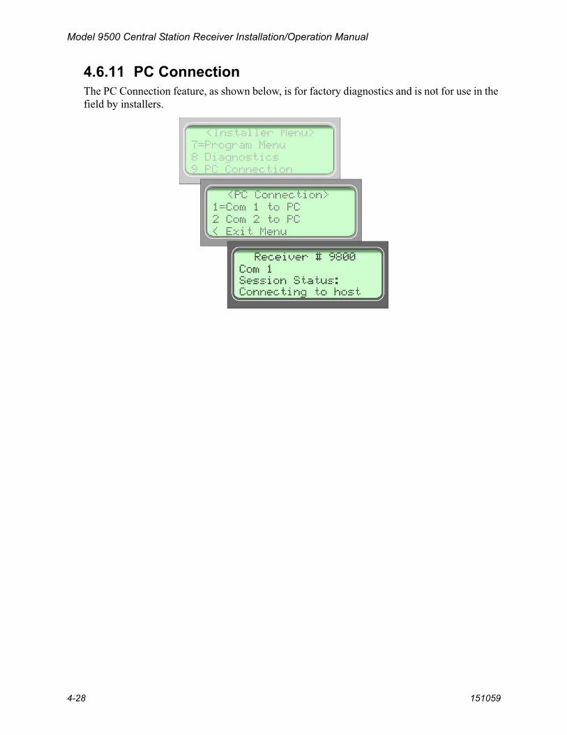
Model 9500 Central Station Receiver Installation/Operation Manual
4-28 151059
4.6.11 PC ConnectionThe PC Connection feature, as shown below, is for factory diagnostics and is not for use in the field by installers.
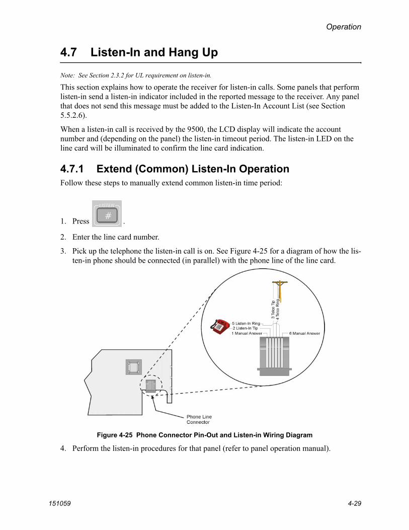
Operation
151059 4-29
4.7 Listen-In and Hang Up
Note: See Section 2.3.2 for UL requirement on listen-in.
This section explains how to operate the receiver for listen-in calls. Some panels that perform listen-in send a listen-in indicator included in the reported message to the receiver. Any panel that does not send this message must be added to the Listen-In Account List (see Section 5.5.2.6).
When a listen-in call is received by the 9500, the LCD display will indicate the account number and (depending on the panel) the listen-in timeout period. The listen-in LED on the line card will be illuminated to confirm the line card indication.
4.7.1 Extend (Common) Listen-In OperationFollow these steps to manually extend common listen-in time period:
1. Press .
2. Enter the line card number.
3. Pick up the telephone the listen-in call is on. See Figure 4-25 for a diagram of how the lis-ten-in phone should be connected (in parallel) with the phone line of the line card.
Figure 4-25 Phone Connector Pin-Out and Listen-in Wiring Diagram
4. Perform the listen-in procedures for that panel (refer to panel operation manual).

Model 9500 Central Station Receiver Installation/Operation Manual
4-30 151059
4.7.2 PBX OperationPrior to performing listen-in functions on a PBX phone line system the receiver must be set up with the proper listen-in mode and PBX string. Refer to Sections 5.2 and 5.5.2.6 to properly program the receiver to handle PBX listen-in calls.
4.8 Testing the System
Because there are so many variations in dialer parameters and phone line conditions, the only way to be absolutely certain that all subscribers can communicate with the 9500 is to test every subscriber's dialer individually. Subscribers must test their communicators every 30 days to make sure the 9500 receives the information.
When you install a new 9500, test every manufacturers' panels for each format. This is necessary because different manufacturers' panels may operate differently even if all panels use the same format.
IMPORTANT:
The 9500 should be tested regularly to ensure complete and proper operation. Reports of automatic signal receipt must be verified daily. All testing, inspection, and maintenance must be done in accordance with NFPA 72 requirements.

151059 5-1
Section 5Programming
This section lists the programmable features in programming mode and the procedures for each of them. The options available are General Options, line card options, and user options.
5.1 UL 864 Programming Requirements
5.2 How to Enter Program Mode
Follow these steps to enter into program mode:
1. Log on to the receiver (see Section 4.4.4 for log on procedure).
2. Press the button.
3. Press the button.
The display will briefly displayInitializingPlease wait . . .
4. Select the option you wish to program. See Appendix A for a quick reference chart of all programming options.
NOTICE TO USERS, INSTALLERS, AUTHORITIES HAVING JURISDICTION, AND OTHER INVOLVED PARTIES: This product
incorporates field programmable software. In order for the product to comply with the requirements in the Standard for Control Units and Accessories for
Fire Alarm Systems, UL 864, certain programming features or options must be limited to specific values or not used at all as indicated below.
Programming Option Permitted inUL 864 (Y/N)
PossibleSettings
Settings Permitted in UL 864
Battery Backup Cfg Yes No Battery BkpDC BkpBattery Bkp
Battery Bkp

Model 9500 Central Station Receiver Installation/Operation Manual
5-2 151059
5.2.1 Programming FieldsIn program mode there are three types of programming fields that data can be entered into. Table 5-1 list the three types of fields and the various parameters associated with them.
5.2.2 How to Maneuver Around in Program ModeFigure 5-1 shows what keys on the touchpad are used to maneuver in program mode.
Figure 5-1 Programming Controls
Table 5-1: Types of Programming Fields
Type of Field Control Keys Comments
Numericthrough
or keys
These fields require a numeric entry only.
List keysPredefined choices are put in a list and can be selected by pressing the up or down arrow keys.
Editthrough
or keys
Enter a number from the numeric keypad or enter any special characters by pressing the up or down arrow keys.

Programming
151059 5-3
5.3 Programming Choices
In programming mode your first set of choices are General Options, line card options, and user list. (Each of these choices will be described in greater detail in the following sections.) Figure 5-2 shows what the display will look like before and after the down arrow is pressed. See Appendix A for a quick reference chart of all programming options.
Figure 5-2 Program Menu Choices
5.4 General Options
This section describes how to configure General Options under the Program menu (see Figure 5-3). You can configure the following items from General Options:
• Receiver operation mode
• Display options
• Communications options
• System options
• Message queue options
Figure 5-3 General Options Display

Model 9500 Central Station Receiver Installation/Operation Manual
5-4 151059
5.4.1 Operation ModeOperation mode chooses how the receiver will operate in normal mode (manual, automatic or log only operation). See Table 5-2 for a description of choices available under the Operation Mode menu item.
Figure 5-4 Normal Operating Mode Display Indicating Manual Operation
Table 5-2: Operations Mode Options and DescriptionsGeneralOptions
ItemsLevel 1 Choices Level 2 Choices Level 3 Choices Comments
Operation Mode
ManualRequires manual acknowledgments of each call or event from an operator. Default.
Log OnlyAll event information is internally acknowledged and put into event history buffer.
Automatic
All event information is sent directly to the automation computer and must be acknowledged by the automation software.
In normal operatingmode the display indicatesthe current Operation Mode

Programming
151059 5-5
5.4.1.1 How to Change the Operation ModeFollow these steps to change the Operation Mode of the receiver:
1. Log on to the receiver. (See Section 4.4.4 for log on procedure.)
2. Press .
3. Press for program menu.
The display will briefly display InitializingPlease wait . . .
4. Press to choose General Options.
5. Press to choose Operation Mode.
The current operation mode will flash in the display.
6. Press or to move through the Operation Mode choices.
Note: Each additional press of the up or down arrow key will toggle the Operation Mode setting to the next choice.
7. When the display flashes on the desired operation mode, press .

Model 9500 Central Station Receiver Installation/Operation Manual
5-6 151059
5.4.2 Display OptionsDisplay options lets you customize the visual outputs of the receiver. These items include language formats, the time display, how events are sorted to the LCD display, or whether or not to hold unacknowledged events. Table 5-3 lists the available choices and gives a description of those choices.
Figure 5-5 View of Display Options
Table 5-3: Display Options and DescriptionsGeneralOptions
ItemsLevel 1 Choices Level 2 Choices Level 3 Choices Comments
Display Options
LanguageEnglish Default: English.
See Section 5.4.2.1.español
Time FormatAM/PM
AM/PM is used for 12 hour time clock displays. Default: AM/PM. See 5.4.2.2.
24 Hour Military time standard. See Section 5.4.2.2 for step-by-step instructions.
Date Format
M/D/Y M = month, D = day, and Y = year.Default: M/D/Y.See Section 5.4.2.3.
Y-M-D
D·M·Y
Daylight Saving Time
Yes/No Default: Yes.See Section 5.4.2.4.Start Month Jan –Dec
Start Week 1st – 4th and Last
End Month Jan –Dec
End Week 1st – 4th and Last

Programming
151059 5-7
Display Options(cont.)
Edit ITI Options
AttemptsYes Affects printer output for ITI calls
only.Default on all options: No.See Section 5.4.2.5.
No
CPU TimeYes
No
CPU TypeYes
No
Panel RevYes
No
Arming LevelYes
No
FMT(Edit Format options)
FSK1Code If “English” is selected then the printer
and LCD output for calls of these formats will be text descriptions. If “Code” is selected then the printer and LCD output for calls of these formats will be the Code and Zone numbers.See Section 5.4.2.6.
English (default)
BFSKCode
English
SIA
Code If “English” is selected, the printer and LCD output will be text. If “Code” is selected then the printer and LCD will display the SIA codes followed by zone or other information. See Section 5.4.2.6.
English (default)
CID
Code (default) This option only affects the SK Expanded automation protocol output. If “English” is selected each event will be sent to the automation as two SIA events; the first with the two digit Group number and the second with the three digit ID number. If Code is selected, each event is sent as eleven digits; two digits Message type, one-digit Event Qualifier, three-digit Event Code, two-digit Group Number, and three-digit ID number. See Section 5.4.2.6.
English
PULSE
0 .. 9 If 0 .. 9 is selected hexadecimal digits B through F are forced to 0 as in the way the 9000 receiver does it, or if 0 .. F is selected digits are sent as is.
0 .. F
SK9000
Packed Each data packet to the automation contains a single (unpacked) or multiple (packed) events. See Section 5.4.2.6.
Unpacked
ACRON
Zero If set to Space then zero characters are translated as a space, if set to Zero then a zero is sent as a zero. See Section 5.4.2.6.
Space
GeneralOptions
ItemsLevel 1 Choices Level 2 Choices Level 3 Choices Comments

Model 9500 Central Station Receiver Installation/Operation Manual
5-8 151059
5.4.2.1 How to Change Language Display1. Enter program mode. (See Section 5.1.)
2. Press for General Options.
3. Press for Display Options.
4. Press until the display flashes on the language format field.
5. Press or until the display flashes on the desired setting.
6. Press .
5.4.2.2 How to Change Time Format Display1. Enter program mode. (See Section 5.1.)
2. Press for General Options.
3. Press for Display Options.
4. Press until the display flashes on the time format field.
5. Press until the display flashes on the desired setting.
6. Press .
Display Options(cont.)
FMT(Edit Format options)
HISPEED
SIA If set to SIA then an event is translated to SIA format when sent to the automation computer. See Section 5.4.2.6.
HiSpeed
VirtualPrinter
If set to Printer, line card slot numbers are sent to SK9000 automation and printer.
AllIf set to All, virtual line numbers are sent to SK9000 automation and printer.
Hold Last Event
Yes If Yes, LCD will display the last acknowledged event instead of the date/time display in the auto mode. In manual mode the display will show the oldest unacknowledged event. See Section 5.4.2.6.
No
GeneralOptions
ItemsLevel 1 Choices Level 2 Choices Level 3 Choices Comments

Programming
151059 5-9
5.4.2.3 How to Change Date Format Display1. Enter program mode. (See Section 5.1.)
2. Press for General Options.
3. Press for Display Options.
4. Press until the display flashes on the date format field.
5. Press or until the display flashes on the desired setting.
6. Press .
5.4.2.4 How to Set/Change Daylight Saving TimeThe 9500 has an automatic Daylight Saving Time (DST) adjustment feature. Before January 2007, if this feature is enabled (set to Yes), the system clock will switch to DST on the first Sunday in April at 2:00 a.m. and revert to standard time on the last Sunday in October at 2:00 a.m. After January 2007, if this feature is enabled, the system clock will start and end DST according to the settings made in the DayLtSv under Display Options.
1. Enter program mode. (See Section 5.1.)
2. Press for General Options.
3. Press for Display Options.
4. Press until the display flashes on the Daylight Saving Time (DayLtSv) field.
5. Press .
6. Make the desired changes.
7. Press .

Model 9500 Central Station Receiver Installation/Operation Manual
5-10 151059
5.4.2.5 How to Edit ITI OptionsIf one of the following ITI options is turned on (set to Yes) then the LCD and printer outputs will include that information.
• Attempts
• CPU Time
• CPU Type
• Panel Rev
• Arming Level
To set these Display Options follow these steps:
1. Enter program mode. (See Section 5.1.)
2. Press for General Options.
3. Press for Display Options.
4. Press until the display flashes on the <ITI> savings field.
5. Press .
6. Press or until the equal sign is on the desired option.
7. Press to change the setting of that option.
Note: Additional presses of the enter button will toggle the setting between Yes and No.
8. Repeat steps 6 and 7 for any other ITI display options you wish to edit.

Programming
151059 5-11
5.4.2.6 How to Edit Format (FMT) Options1. Enter program mode. (See Section 5.1.)
2. Press for General Options.
3. Press for Display Options.
4. Press until the display flashes on the FMT field.
5. Press .
6. Press or until the display highlights the desired format.
7. Press or to select the desired setting for that format.
8. Repeat steps 6 and 7 as needed for each format.
5.4.2.7 How to Set Hold Last Event1. Enter program mode. (See Section 5.1.)
2. Press for General Options.
3. Press for Display Options.
4. Press until the display flashes on the hold last event field.
5. Press or until the display flashes on the desired setting.
6. Press .

Model 9500 Central Station Receiver Installation/Operation Manual
5-12 151059
5.4.3 CommunicationsIn the communication option the installer can configure the communication ports, automation configuration, annunciator configurations, and the auxiliary relay configurations. Table 5-4 lists the available choices and gives a description of those choices.
Figure 5-6 Communications Options Menu
Table 5-4: Communication Options and Description GeneralOptions
ItemsLevel 1 Choices Level 2 Choices Level 3 Choices Comments
Communications Port Functions
Com1
Unused Rules for Port Configuration:Functions in Brackets [ ] appear only if “Automation” is selected for Com1.Functions in { } appear only if“Printer” is selected in Com1 or Par.A function may be selected only once in the 3 ports (only one printer, only one Diag, etc.).All ports may be configured “Unused”.See Section 5.4.3.1.
Printer
Automation
Com2
Unused
Diagnostics Outputs raw hex-ASCII code output.
Printer English output to printer.
[Auto Bkp]Acts as a backup print output port if a fault occurs with the primary automation port.
[Auto Bkp Prn] Acts as a backup print output port if a fault occurs with the automation port.
{Print Bkp} Acts as a backup printer port if a fault occurs with the primary printer port.
Par
Unused Default
Diagnostics Outputs raw hex-ASCII code output.
Printer English output to printer.
[Auto Bkp] Acts as a backup print output port if a fault occurs with the automation port.

Programming
151059 5-13
Communications(cont.)
Com Port 1
Baud Rate38400/19200/9600/7200/4800/2400/1200/600/300/110
Default: 19200. See Section 5.4.3.2.
D (# Data Bits) 7, 8 Default: 8. See Section 5.4.3.2.
S (# Stop Bits) 1, 2 Default: 1. See Section 5.4.3.2.
P (Parity) Even, Odd, Space, Mark, No
Default: None. See Section 5.4.3.2.
F (Flow Control)
Hdwr Unidirectional communication. Default. See Section 5.4.3.2.
Sftwr Bi-directional communication. See Section 5.4.3.2.
None No supervision. See Section 5.4.3.2.
Init String Two 20 character ESC command sequences. See Section 5.4.3.4.
Com Port 2 Same as Com Port 1 See Section 5.4.3.3.
Par Port Init String Two 20 character ESC command sequences. See Section 5.4.3.4.
Automation Config
Format
SK EXP, SK9000, SIA CIS, CAPS, FBI I220, ADEM 685, ITIComp, ITI Gen
See Automation Communication Protocols Reference Guide (PN 151393) for more information on automation formats. Additional ITI options described in Table 5-6.Default: SK9000. See Section 5.4.3.5.
Hex
Y = Enabled If enabled, any call data that is determined to be bad data will be output in Hex format. This option is only visible when SK 9000 format is selected. Default: Disabled. See Section 5.4.3.5.
N = Disabled
Heart Beat
Y = Enabled A supervisory signal that continually tests the communication link between the automation computer and the receiver. Default: Disabled. See Section 5.4.3.5.
N = Disabled
Time (of Heartbeat) 10-600 Seconds
How often a supervisory signal (a heartbeat) is sent to the automation computer. Default: 0. See Section 5.4.3.5.
Ack timeout 1 to 120 Seconds 15 seconds or less in UL applications. Default: 10 sec. See Section 5.4.3.5.
GeneralOptions
ItemsLevel 1 Choices Level 2 Choices Level 3 Choices Comments

Model 9500 Central Station Receiver Installation/Operation Manual
5-14 151059
5.4.3.1 How to Set Up Port FunctionPort functions set up how each of the communication ports will be used. Before you start to set up the port functions review the rules for port functions in Table 5-4.
1. Enter program mode. (See Section 5.1.)
2. Press for General Options.
3. Press for Communications.
4. Press to set port functions.
5. Press or until the display flashes on the desired port setting.
6. Press .
7. Repeat steps 5 through 6 until all port functions are set.
8. Press to exit menu.
Communications(cont.)
AnnunciatorConfiguration
Printer
Yes or No
Yes = will annunciate if an event, trouble or fault condition occurs.No = no annunciation if an event, trouble or fault condition occurs.Default for all options: Yes.See Section 5.4.3.6.* Listen In option must be set to No
for UL installations.
Bkp Printer
Auto Comp
Bkp Auto Comp
Battery
Device
Line Fault
AC Power
Buffer Full
Listen In*
Call Pending
Aux Relay CfgOptions the same as Annunciator Configuration.See Section 5.4.3.7.* Listen In option must be set to No for UL installations.
GeneralOptions
ItemsLevel 1 Choices Level 2 Choices Level 3 Choices Comments

Programming
151059 5-15
5.4.3.2 How to set Com Port 1 ParametersSet the baud rate, the number of data bits, number of stop bits, the parity, and the flow control (see Table 5-4 for choice details).
1. Enter program mode. (See Section 5.1.)
2. Press for General Options.
3. Press for Communications.
4. Press to set Com Port1 parameters.
5. Press or until the display flashes on the desired port setting.
6. Press .
Note: See “How to Edit Init String” in Section 5.4.3.4.
7. Repeat steps 5 through 6 until all parameters are set.
8. Press to exit menu.
5.4.3.3 How to Set Com Port 2 ParametersSet the baud rate, the number of data bits, number of stop bits, the parity, and the flow control (see Table 5-4 for choice details).
1. Enter program mode. (See Section 5.1.)
2. Press for General Options.
3. Press for Communications.
4. Press to set Com Port2 parameters.
5. Press or until the display flashes on the desired port setting.
6. Press .
Note: See “How to Edit Init String” in Section 5.4.3.4.
7. Repeat steps 5 through 6 until all parameters are set.
8. Press to exit menu.

Model 9500 Central Station Receiver Installation/Operation Manual
5-16 151059
5.4.3.4 How to Edit Init String (Par Port)An initialization string can be used to customize the output to the device connected to a port on the receiver.
For example, you can skip over perforations, set proportional spacing, or condense the print output to a printer.Note: Refer to the user manual, of the device connected to the receiver, for special command sequences.
Follow these step to insert an initialization string:
1. Press at the flashing <Init Str> field.
Figure 5-7 Initialization String Display
2. Press the or until the desire character flashes.
3. Press , the next character position will flash.
4. Repeat steps 2 and 3 until the desired sequence is complete.
5. Press .
6. Repeat steps 2 through 5 for the second string.
Table 5-5: Initialization String Characters
Character Description
0-9 Numeric characters, which can be entered from the touchpad or up/down arrows.
a-z and A-Z Alpha characters entered with the up/down arrows.
: _ - . , & * # ? EC and space bar.
Special Characters entered with the up/down arrows.

Programming
151059 5-17
To clear an init string:
1. At the Clear String field, press until the desired option flashes (Figure 5-7).
2. Press .
3. Press to exit menu.
5.4.3.5 How to Set Automation CommunicationThrough this option the automation communication format and parameters can be set up. (See Table 5-4 for format choices.)
How to Set the FormatFollow these steps to set the automation communication format.
1. Enter Program mode. (See Section 5.1.)
2. Press for General Options.
3. Press for Communications.
4. Press to setup automation configuration.
5. Press the or button until the display flashes on the desired port setting.
6. Press .
7. Press if you wish to exit menu or continue with heartbeat.
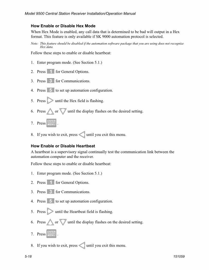
Model 9500 Central Station Receiver Installation/Operation Manual
5-18 151059
How Enable or Disable Hex ModeWhen Hex Mode is enabled, any call data that is determined to be bad will output in a Hex format. This feature is only available if SK 9000 automation protocol is selected.Note: This feature should be disabled if the automation software package that you are using does not recognize
Hex data.
Follow these steps to enable or disable heartbeat:
1. Enter program mode. (See Section 5.1.)
2. Press for General Options.
3. Press for Communications.
4. Press to set up automation configuration.
5. Press until the Hex field is flashing.
6. Press or until the display flashes on the desired setting.
7. Press .
8. If you wish to exit, press until you exit this menu.
How Enable or Disable HeartbeatA heartbeat is a supervisory signal continually test the communication link between the automation computer and the receiver.
Follow these steps to enable or disable heartbeat:
1. Enter program mode. (See Section 5.1.)
2. Press for General Options.
3. Press for Communications.
4. Press to set up automation configuration.
5. Press until the Heartbeat field is flashing.
6. Press or until the display flashes on the desired setting.
7. Press .
8. If you wish to exit, press until you exit this menu.
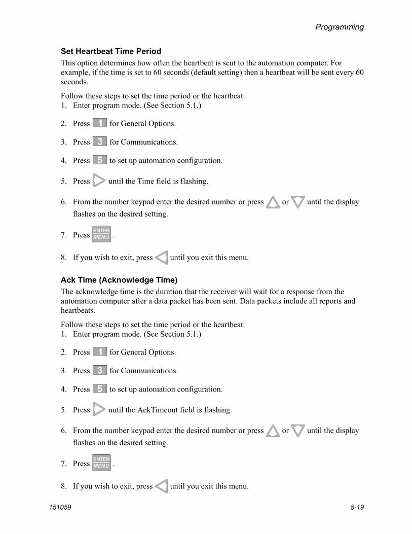
Programming
151059 5-19
Set Heartbeat Time PeriodThis option determines how often the heartbeat is sent to the automation computer. For example, if the time is set to 60 seconds (default setting) then a heartbeat will be sent every 60 seconds.
Follow these steps to set the time period or the heartbeat:1. Enter program mode. (See Section 5.1.)
2. Press for General Options.
3. Press for Communications.
4. Press to set up automation configuration.
5. Press until the Time field is flashing.
6. From the number keypad enter the desired number or press or until the display flashes on the desired setting.
7. Press .
8. If you wish to exit, press until you exit this menu.
Ack Time (Acknowledge Time)The acknowledge time is the duration that the receiver will wait for a response from the automation computer after a data packet has been sent. Data packets include all reports and heartbeats.
Follow these steps to set the time period or the heartbeat:1. Enter program mode. (See Section 5.1.)
2. Press for General Options.
3. Press for Communications.
4. Press to set up automation configuration.
5. Press until the AckTimeout field is flashing.
6. From the number keypad enter the desired number or press or until the display flashes on the desired setting.
7. Press .
8. If you wish to exit, press until you exit this menu.

Model 9500 Central Station Receiver Installation/Operation Manual
5-20 151059
ITI Options (Only Visible if ITI Gen or ITIComp Formats are Chosen)These are options particular to the ITI automation format and can only be edited if one of these formats is used to communicate with the automation computer. See AutomationCommunication Protocols Reference Guide (PN 151393) for detailed information.
Follow these steps to set the ITI options:
1. Enter program mode. (See Section 5.1.)
2. Press for General Options.
3. Press for Communications.
4. Press to set up automation configuration.
5. Press until the ITI field is flashing.
6. Press .
Note: ITI automation formats are covered in greater detail in Automation Communication Protocols Reference Guide (PN 151393).
Table 5-6: ITI Automation Format Options
Option Choices Default Description
Log Recs Y (Yes)N
Log records identify the time and date of a incoming report.
N (No)
XID Y (Yes)N
Extended panel Identification code. See Automation Communication Protocols Reference Guide (PN 151393).
N (No)
SupCh
s
Supervisory Character is sent from the automation computer. The receiver will respond with an OKAY or supervisory record. See Automation Communication Protocols Reference Guide (PN 151393).
No Data 0 Identifies the no data character in the log record.
Generic Rev 6.1 & 6.2 6.1

Programming
151059 5-21
Log Recs (For ITI Formats):
1. At the flashing Log Recs field press or until the display flashes on the desired setting.
2. Press .
3. If you wish to exit, press until you exit this menu.
XID (Extended ID for ITI Panels):
1. At the flashing XID field press or until the display flashes on the desired setting.
2. Press .
3. If you wish to exit, press until you exit this menu.
SupCh (Supervisory Character):
1. At the flashing SupCh [s] field press or until the display flashes on the desired setting.
2. Press .
3. If you wish to exit, press until you exit this menu.
NoData (No Data Character for Log Record):
1. At the flashing NoData[0] field enter a digit from 0-9 from the touchpad or press
or until the display flashes on the desired setting.
2. Press .
3. If you wish to exit, press until you exit this menu.

Model 9500 Central Station Receiver Installation/Operation Manual
5-22 151059
5.4.3.6 How to Configure the On-board Annunciator OutputsProgram what will give a trouble annunciation or what will not annunciate from the on-board annunciator.
1. Enter program mode. (See Section 5.1.)
2. Press for General Options.
3. Press for Communications.
4. Press to set annunciator configuration.A list of the annunciator output options appears.
5. Press or to move through the annunciator output options.
6. When the equal sign highlights the option you wish to change, press .
Note: Additional presses of the enter button toggle the setting between “yes” or “no”. See Table 5-4.
7. Repeat steps 5 through 6 for all annunciator options you wish to change.
5.4.3.7 How to Configure the Auxiliary Relay OutputsProgram what will give a trouble output to the auxiliary relay contact. (To program the normal state of the auxiliary relay see Section 5.4.4.)
1. Enter program mode. (See Section 5.1.)
2. Press for General Options.
3. Press for Communications.
4. Press to set relay configuration.
A list of the relay output options appears.
5. Press or to move through the relay output options.
6. When the equal sign highlights the option you wish to change, press .
Note: Additional presses of the enter button toggle the setting between “yes” or “no”. See Table 5-4.
7. Repeat steps 5 through 6 for all relay options you wish to change.
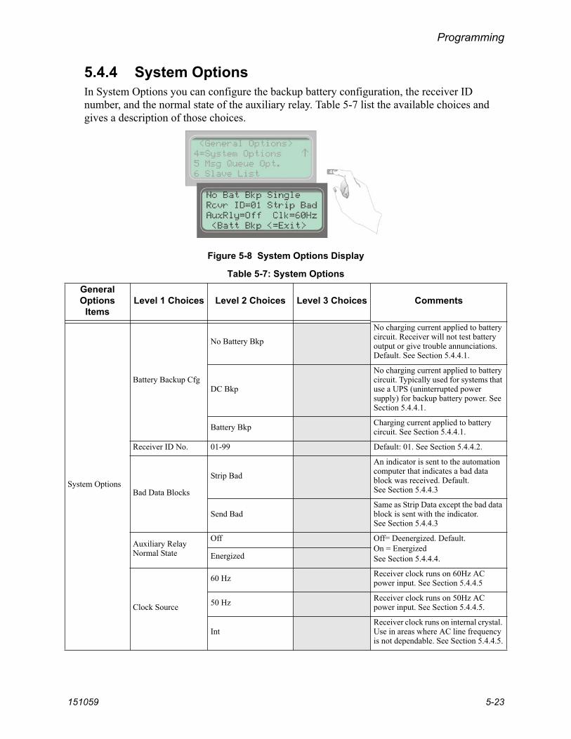
Programming
151059 5-23
5.4.4 System OptionsIn System Options you can configure the backup battery configuration, the receiver ID number, and the normal state of the auxiliary relay. Table 5-7 list the available choices and gives a description of those choices.
Figure 5-8 System Options Display
Table 5-7: System Options GeneralOptions
ItemsLevel 1 Choices Level 2 Choices Level 3 Choices Comments
System Options
Battery Backup Cfg
No Battery Bkp
No charging current applied to battery circuit. Receiver will not test battery output or give trouble annunciations. Default. See Section 5.4.4.1.
DC Bkp
No charging current applied to battery circuit. Typically used for systems that use a UPS (uninterrupted power supply) for backup battery power. See Section 5.4.4.1.
Battery Bkp Charging current applied to battery circuit. See Section 5.4.4.1.
Receiver ID No. 01-99 Default: 01. See Section 5.4.4.2.
Bad Data Blocks
Strip Bad
An indicator is sent to the automation computer that indicates a bad data block was received. Default. See Section 5.4.4.3
Send BadSame as Strip Data except the bad data block is sent with the indicator.See Section 5.4.4.3
Auxiliary Relay Normal State
Off Off= Deenergized. Default.On = EnergizedSee Section 5.4.4.4.Energized
Clock Source
60 Hz Receiver clock runs on 60Hz AC power input. See Section 5.4.4.5
50 Hz Receiver clock runs on 50Hz AC power input. See Section 5.4.4.5.
IntReceiver clock runs on internal crystal. Use in areas where AC line frequency is not dependable. See Section 5.4.4.5.

Model 9500 Central Station Receiver Installation/Operation Manual
5-24 151059
5.4.4.1 How to Change Backup Battery SettingThrough System Options the backup battery can be configured for the type of backup battery your installation site requires.
1. Enter program mode. (See Section 5.1.)
2. Press for General Options.
3. Press for System Options.
4. Press or until the display flashes on the desired setting.
5. Press .
To Exit press until you return to the main menu.
5.4.4.2 How to Set the Receiver ID Number1. In large central stations where calls may be coming in on several receivers at once, the
automation software will need to identify which receiver it received a call from. This will help in troubleshooting if a problem occurred with the automation system or receiver.
2. Enter program mode. (See Section 5.1.)
3. Press for General Options.
4. Press for System Options.
5. Press until the Receiver ID programming field is flashing Rcvr ID=01.
6. The display will flash on the receiver ID number: Rcvr ID=01
7. Enter the desired receiver ID number (a number from 01 to 99).
8. Press .

Programming
151059 5-25
5.4.4.3 How to Configure Output for Bad Data BlocksThis feature selects how bad data blocks will be sent from the receiver to the automation computer. If Strip Bad is selected then an indicator will be sent to the automation computer when a bad data block is received, but the actual bad data block will not be sent. If Send Bad is selected an indicator will be sent to the automation computer along with the bad data block.
1. Enter program mode. (See Section 5.1.)
2. Press for General Options.
3. Press for System Options.
4. Press until display will flashes on the Bad Data Blocks: Strip_Bad
5. Press or until the display flashes on the desired setting.
6. Press .
To Exit press until you return to the main menu.
5.4.4.4 How to Set the Normal State of the Auxiliary Relay ContactThe auxiliary relay contact is a Form C relay. This feature allows you to set the state of the auxiliary relay normally open contact when power is applied to the receiver.
1. Enter program mode. (See Section 5.1.)
2. Press for General Options.
3. Press for System Options.
4. Press until display will flash on the auxiliary relay setting: Aux Relay=Off
5. Press or until the display flashes on the desired setting.
6. Press . To Exit press until you return to the main menu.

Model 9500 Central Station Receiver Installation/Operation Manual
5-26 151059
5.4.4.5 Select the Receivers Clock SourceThe receiver can use 50 Hz, 60 Hz, or an internal crystal to calculate time. Select the internal setting if you are in an area where the AC line frequency is not dependable and you wish to have the receiver calculate the time using an internal crystal. The internal crystal is not as accurate as the AC power source, and normally you should select 60 Hz or 50 Hz.
1. Enter program mode. (See Section 5.1.)
2. Press for General Options.
3. Press for System Options.
4. Press until display will flash on the auxiliary relay setting: Clk=60Hz
5. Press or until the display flashes on the desired setting.
6. Press . To Exit press until you return to the main menu.
5.4.5 Message Queue OptionsThe Message Queue option lets you adjust some settings on how the receive handles incoming events. See Section 7 for trouble messages.
Figure 5-9 Message Queue Display
Note: The “Warning On” can be set from 10% to 99%, the “Warning Off” can be set from 1% to 90%. A mini-mum separation of 5% will be set between the On % and the Off %. For example, if the “Warning On” is set to 82% the “Warning Off” maximum setting can be 77%.

Programming
151059 5-27
Table 5-8: Message Queue Option
5.4.5.1 Set the Message Queue Warning On LevelSet the percentage of how full the message queue can get before the receiver indicates a “Message Queue Warning” condition.
1. Enter program mode. (See Section 5.1.)
2. Press for General Options.
3. Press for Message Queue Options.
4. Enter the level (in %) you wish the receiver message queue to get before it will indicate a message queue warning in the Wrn Lvl On field.
5. Press .
To Exit press until you return to the main menu.
GeneralOptions Level 1 Choices Level 2 Choices Level 3 Choices Comments
Message Queue Options
% Warning Lvl
On: 10 to 99%
Percentage full message queue must reach before a trouble indication occurs. Default: 75%. See Section 5.4.5.1.
Off: 01 to 90%Percentage message queue must drop to clear a trouble indication. Default: 50%. See Section 5.4.5.2.
Event Release Sec. 1, 20 to 120 secTime from call beginning until eventsreleased to system. Default: 60 sec. See Section 5.4.5.3.

Model 9500 Central Station Receiver Installation/Operation Manual
5-28 151059
5.4.5.2 Set the Message Queue Warning Off LevelSet the percentage level where the receiver will indicate a restore condition for a “Message Queue Warning”.
1. Enter program mode. (See Section 5.1.)
2. Press for General Options.
3. Press for Message Queue Options.
4. Press until the display flashes on the Off field.
5. Enter the level (in %) you wish the receiver message queue to get before it will indicate a message queue warning restore.
6. Press .
5.4.5.3 Set the Event Release TimeUsed to define the maximum amount of time (in seconds) that the receiver will hold an event in memory prior to sending it to automation, VFD, and printer. The time begins at the beginning of the call or on an acknowledgement.Note: For 9815 line cards, if the Event Release setting is greater than the Call Hang-Up setting the receiver will
not disconnect the line (panel) until the Event Release time has expired. The actual amount of time before the receiver disconnects a line may at times be greater than the actual programmed value for Call Hang-Up Time. An event in progress (Event Release) has to complete before the call hang-up takes effect.
1. Enter program mode. (See Section 5.1.)
2. Press for General Options.
3. Press for Message Queue Options.
4. Press until the display flashes on the Event Release field.
5. Enter the event release time (001 or 020 to 120) in seconds.
6. Press .

Programming
151059 5-29
5.5 Line Device Menu
You can add, edit, clear (delete), or view existing line cards from the Line Device Menu. Figure 5-10 shows the sequence used to reach the Line Card Menu. Appendix A shows all of the options available in the Line Device Menu.
Figure 5-10 The Line Device Menu Options
Model 9500 Central Station Receiver Installation/Operation Manual
5-30 151059
5.5.1 Add DeviceLine cards are added automatically if you power down the receiver and then add the line card. If, however, you swap out a line card with the receiver on, you will need to use the Add Device option.
To program in a new line card follow these steps:
1. Install the new line card. (See Section 3.4.)
2. Log on to the receiver. (See Section 4.4.4 for log on procedure.)
3. Press .
4. Press for the Program Menu.The display will briefly display Initializing
Please wait . . .
5. Press to choose Line Device Menu.The display will show <Select Device Type>.
6. Press if the line card is a 9810, and press if the line card is a 9815. If you have only one line card model installed, only that model number will display.
7. Press to add a new line card.The display will show <Add Device> _ _
Enter Device #:
8. Enter the line card slot number (1-2).
9. Press .
10. Press to use line card defaults set at the factory, or press to use copy the pro-gramming of another line card.

Programming
151059 5-31
5.5.2 Edit Line Card
Due to the increasing number of formats a single line can accept and the wide variety of manufacturer’s specifications for handshake/acknowledgment tones required for their digital dialers to communicate, Silent Knight strongly recommends the following for handshake tone order.
1. Some SIA DCS communicators respond to the 2300Hz handshake. Always place the 2225Hz handshake tone first for line cards accepting SIA DCS format.
2. Some Contact ID communicators respond to the 1400Hz handshake followed by the 2300Hz handshake instead of the dual tone 1400-2300Hz handshake (NAPCO Gemini communicators have been known to do this). Line cards accepting Contact ID should not have the 1400Hz followed by the 2300Hz before the dual tone 1400-2300Hz handshake.
3. SIA DCS communicators will respond to the Modem II and IIe handshakes. If a line card is to accept both SIA DCS and Modem II or IIe, the 2225Hz handshake must come before the Modem II and Modem IIe handshakes.
4. Some Westec panels will respond to the Modem II handshake. If a line card is to accept both Westec and Modem II formats, the Westec handshake must come before the Modem II handshake.
5. Some ITI panels don't respond to the default 2225Hz handshake. They need a lot longer handshake duration than what the 9500 receiver is defaulted as. You don't want to change the default 2225Hz handshake (1st handshake group) because it's optimized for SIA pan-els. What you should do is to program the 2nd 2225Hz handshake group with a long hand-shake duration (say 2550 ms). This way, a SIA panel responds to the 1st 2225Hz handshake and ITI panels respond to the 2nd 2225Hz handshake.
Important!

Model 9500 Central Station Receiver Installation/Operation Manual
5-32 151059
5.5.2.1 Edit Line Card Menu OptionsFrom the Edit Line menu option, you can make changes to line card setting such as handshake sequence, pulse format, and listen-in mode. Table 5-9 describes line card edit options.
Table 5-9: Edit Line Card Menu Options
Line Card Menu Choice Choice Choice Default Comments
Edit Line
HandshakeSequence
SequenceNumber
1 to 6
See Table 5-10
The order in which the line card will output different handshakes. Number 1 is sent first and number 6 is sent last. See page 5-37.
Format Group
2225 Hz2300 Hz1400 Hz1400_2300HzWestecModem IIeModem IIReserved1400_2300-2Not Used
Defaults apply only in relation to each SequenceNumber
Handshake type. See page 5-37
HS Duration*
9810:0 to 250 msec9815:0 to 9999 msec
Length of time the receiver will send a handshake tone.See page 5-38.
Max Wait†
Length of time the receiver will wait for data from the reporting panel before sending the next handshake tone.See page 5-39
Ack Duration*Length of time the receiver will send an acknowledgement tone to the reporting panel. See page 5-39
Pulse Format
5-digit Format
4/1 If a pulse comes in a 5-digit format the data is treated as the selected format.
3/2
3/1CS 3 by 1 w/Check sum
6-digit Format
4/2 If a pulse comes in a 6-digit format then the data will then be treated as the selected format.
3/2CS 3 by 2 w/Check sum
4/1CS 4 by 1 w/Check sum
Timeout (Inter-digit Tm [ms]) 300 ms to 2 Sec.
This feature selects the time period between data blocks. If 0000 is selected then the receiver will use an automatic algorithm.
Ack/Even (Ack on Even Round)
Yes Select this option if the 1400 or 2300 Hz format requires a Ack tone on even rounds.No
Part (Partially Extended)
Yes Select this option if you have multiple extended data blocks for 3/1 or 4/1 formats.No
* Each numeric option is 10 times the displayed value. Example–064 X 10 = 640 msec.† Each numeric option is 50 times the displayed value. Example–004 X 50 = 200 msec.

Programming
151059 5-33
Edit Line(cont.)
Line Options
Direct
Y (Yes) Y = dedicated or direct connect phone line.N = used for standard phone lines. See page 5-41 for more information.
No (No)
Number of Rings
000-255
002
Number of rings the line card needs to receive before it will answer a call. It is recommended that number of rings is not set higher than 005. If Caller ID is turned on, set to 002 (see section 5.5.2.8 for more information on the Caller ID option). See page 5-42 for more information on Number of Rings.
On time 1-255 in 50ms periods 010 (500ms) 9810 line card only. See page 5-42
for more information.
Off time 1-255 in 50ms periods 010 (500ms) 9810 line card only. See page 5-43
for more information.
dB Level
Lo (Low) 9810 line card only. Select the db level of the handshake and acknowledge tones.Hi (High)
Md (Medium)
Country Code See page 5-44 for detailed list USA
9815 line card only. Some Country Code selections support multiple countries. See page 5-44 for detailed list.
Threshold 1-15 in 2.0 VDC steps 08 (16.0VDC) See page 5-45.
Fault Detect (Sample)
0-255 sec - 98100-90 sec - 9815 020 (20 Sec) See page 5-45.
Listen In
Listen Mode
Not Used See page 5-46 for more information. Must not be used in UL installations.Common
PBX PBX edit string
Account List
Add Add up to 20 accounts. See page 5-49.
Edit See page 5-49.
Clear Account See page 5-49.
PBX String edit None Only available if PBX is selected in Listen Mode. See page 5-47.
Timeout 0-255 0 See page 5-48.
Account List
Add Account
None
See page 5-48.
Edit Account
Clear Account
Trap List
Add Account Enter Account #
None
See page 5-50 through page 5-51.
Edit Account Choose Account
Clear Account Choose Account
Table 5-9: Edit Line Card Menu Options
Line Card Menu Choice Choice Choice Default Comments

Model 9500 Central Station Receiver Installation/Operation Manual
5-34 151059
Edit Line (cont.)
Misc. Line Options
Echo Suppress
Y (Yes) Outputs a 2 second 2025 Hz tone to disable echo suppression equipment that may interfere with modem formats. See page 5-52.
N (No)
Caller ID
Yes The Caller ID information will only be sent on incoming call messages that contain no data. If the call message contains any data (valid or invalid) no Caller Id information will be output. See page 5-52.
No
Billing Delay
Y (Yes) Initiates a 2 second delay at the start of each call before the handshake delay.
N (No) See page 5-52 for more information.
Hunt Group
00-99
00
Allows multiple line cards to report under the same group number to the automation software. See page 5-53.
Ring Options Min Ring 30 ms 9815 line card only. See page 5-53.
Max Ring 060 ms
Ring Off 4000 ms
Min Ring Off 450 ms
Ring Off Error 2200 ms
Min # Rings Period 05
Call Hang Up
Max number of seconds the line card will stay off hook for a call. Helps prevent a run away panel from monopolizing the phone line.
Ademco Auto Opt.
BFSK AutoOutH/S Used to setup communication with
a automation system using ADEMCO 685 or CAPS.See Section 5.5.2.9.
4/2
3/1 Restore Out3/1
H/S
4/2 Auto OutH/S
Nor
FBI Printer OutS/Fast
LAR300
Pulse ExtendedExt
No Ext
Extend OutH/S
4/2
Table 5-9: Edit Line Card Menu Options
Line Card Menu Choice Choice Choice Default Comments

Programming
151059 5-35
Edit Device (cont.)
ITI Options Menu
ITI SCode Menu
Default SCode 12345 Used in communication locking on ITI panels.
Add Acct/SCode None
See Section 5.4.2.5 and 5.5.2.10.
Edit Acct/SCode None
Clear Acct/SCode None
Add SCode Table None
Clear SCode Table None
Date/Time FlagRequested
Always
ITI 300 Baud
Yes If enabled, the receiver attempts to negotiate 300 baud communication with ITI panels that support 300 baud. See Section 5.5.2.10.
No
Audio Mode
Instant Select the type of listen in that will be performed for ITI control panels. See Section 5.5.2.10.One Ring
Dial Back
Line Gain Opt
Transmit Gain -3 to 14 dB 8 dB 9815 line card only. Sets line transmit and line receive gain. See Section 5.5.2.11.Receive Gain 0 to 12 db 6 dB
CID MonitorNorm, Prearm, DTMF, or Marks
NormThese options only apply if the Caller ID option is used. See Section 5.5.2.11 for information on the Line Gain Options and page 5-52 for information on the Caller ID option.
CID Gain -6 to 7 dB 7 dB
On Hook Gain 2 to 7 dB 7 dB
Ringer Imped HI or SY HI
Table 5-9: Edit Line Card Menu Options
Line Card Menu Choice Choice Choice Default Comments

Model 9500 Central Station Receiver Installation/Operation Manual
5-36 151059
5.5.2.2 To Enter the Edit Line Card OptionTo edit an existing line card follow these steps:1. Log on to the receiver. (See Section 4.4.4 for log on procedure.)
2. Press .
3. Press to display the Program Menu.
The display will briefly show Initializing
Please wait . . .
4. Press to choose Line Device Menu.
5. Press or to select the line card model you want to edit. Only installed models are displayed in the Select Device Type list (9810 and/or 9815).
6. When the equal sign highlights the model you wish to edit, press .
7. Press to edit the line card.The display will show a list of installed line cards.
8. Press or to move through the available list.
9. When the equal sign highlights the line card you wish to edit, press .The display will show a list of choices. Table 5-9 lists these choices and provides a description of the options.
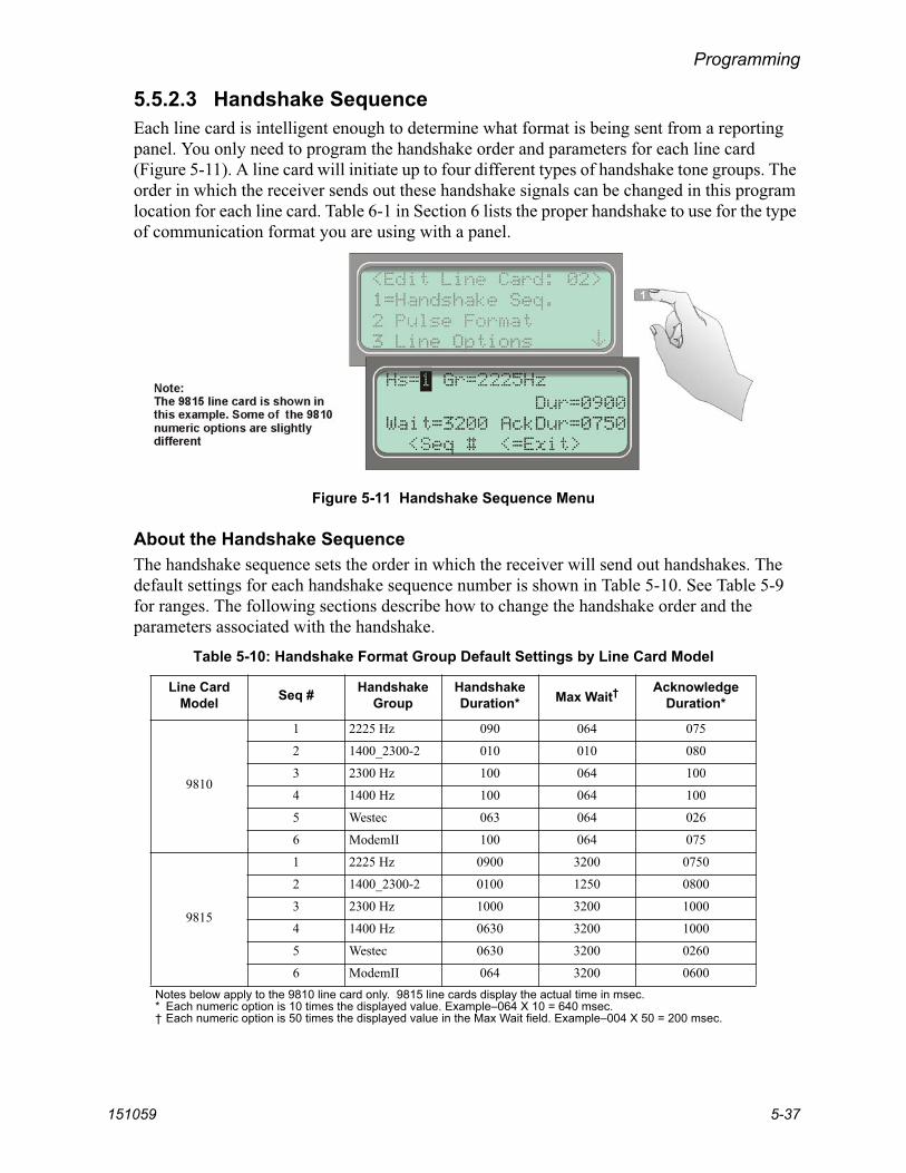
Programming
151059 5-37
5.5.2.3 Handshake SequenceEach line card is intelligent enough to determine what format is being sent from a reporting panel. You only need to program the handshake order and parameters for each line card (Figure 5-11). A line card will initiate up to four different types of handshake tone groups. The order in which the receiver sends out these handshake signals can be changed in this program location for each line card. Table 6-1 in Section 6 lists the proper handshake to use for the type of communication format you are using with a panel.
Figure 5-11 Handshake Sequence Menu
About the Handshake SequenceThe handshake sequence sets the order in which the receiver will send out handshakes. The default settings for each handshake sequence number is shown in Table 5-10. See Table 5-9 for ranges. The following sections describe how to change the handshake order and the parameters associated with the handshake.
Table 5-10: Handshake Format Group Default Settings by Line Card Model
Line Card Model Seq # Handshake
GroupHandshakeDuration* Max Wait†
AcknowledgeDuration*
9810
1 2225 Hz 090 064 075
2 1400_2300-2 010 010 080
3 2300 Hz 100 064 100
4 1400 Hz 100 064 100
5 Westec 063 064 026
6 ModemII 100 064 075
9815
1 2225 Hz 0900 3200 0750
2 1400_2300-2 0100 1250 0800
3 2300 Hz 1000 3200 1000
4 1400 Hz 0630 3200 1000
5 Westec 0630 3200 0260
6 ModemII 064 3200 0600Notes below apply to the 9810 line card only. 9815 line cards display the actual time in msec.* Each numeric option is 10 times the displayed value. Example–064 X 10 = 640 msec.† Each numeric option is 50 times the displayed value in the Max Wait field. Example–004 X 50 = 200 msec.

Model 9500 Central Station Receiver Installation/Operation Manual
5-38 151059
Change the Handshake Sequence Number
1. Follow the procedure in Section 5.5.2.2.
2. Press for handshake sequence menu.
When display flashes on the Seq# (see Figure 5-11).
3. Press or to change the ordered handshake number.
1 = the first handshake tone sent 2 = the second handshake tone to be sent and so on.
4. When the desired sequence number is flashing press orThe display will start flashing the format group field.
Change the Format Group
1. Follow the procedure in Section 5.5.2.2.
2. Press for handshake sequence menu.
3. Press until the display flashes on the Format Group field.
4. Press or to change the format group. See Table 6-1 in Section 6 for your com-munication format.
5. When the desired format group is flashing press or .
Change the Handshake Duration TimeThe handshake duration is the length of time that the receiver will send a handshake tone. See Table 5-10 for valid entries for each line card model.
1. Follow the procedure in Section 5.5.2.2.
2. Press for handshake sequence menu.
3. Press until the display flashes on the Hs duration field.
4. Enter the desired value from the keypad or press or to change the handshake duration time.
5. When the desired handshake duration time is flashing press or .

Programming
151059 5-39
Change the Maximum Handshake Wait TimeThe wait time is the amount of time the receiver will wait for data from the reporting panel before outputting the next handshake sequence. See Table 5-10 for valid entries.
1. Follow the procedure in Section 5.5.2.2.
2. Press for handshake sequence menu.
3. Press until the display flashes on the Max Wait field.
4. Enter the desired value from the keypad or press or to change the wait time.
5. When the desired wait time is flashing press or .
Change the Acknowledgment Tone Duration TimeThe acknowledgment tone duration time is the amount of time the receiver will send an acknowledgment tone to the reporting panel. See Table 5-10 for valid entries.
1. Follow the procedure in Section 5.5.2.2.
2. Press for handshake sequence menu.
3. Press until the display flashes on the Ack duration field.
4. Enter the desired value from the keypad or press or to change the acknowledg-ment tone duration time.
5.5.2.4 Pulse FormatSelect how this line card will handle pulse formats.
Select Which Format a 5-digit Pulse Format will be Received As
1. Follow the procedure in Section 5.5.2.2.
2. Press for pulse format menu.
3. Press until the display flashes on the 5-digit Fmt field.
4. Select the format by pressing or .
5. When the desired wait time is flashing press or .

Model 9500 Central Station Receiver Installation/Operation Manual
5-40 151059
Select Which Format a 6-digit Pulse Format will be Received As
1. Follow the procedure in Section 5.5.2.2.
2. Press for pulse format menu.
3. Press until the display flashes on the 6-digit Pulse Fmt field.
4. Select the format by pressing or .
5. When the desired wait time is flashing press or .
Select the Inter-DigitThis option adjust the time period between data blocks that the receiver will tolerate.
1. Follow the procedure in Section 5.5.2.2.
2. Press for pulse format menu.
3. Press until the display flashes on the Inter-digit field.
4. Enter the desired value from the keypad or press or .
5. When the desired wait time is flashing press or .
Set for 2300 and 1400 formats that Require Acknowledges on Even Rounds
1. Follow the procedure in Section 5.5.2.2.
2. Press for pulse format menu.
3. Press until the display flashes on the Ack on Even Round field.
4. Select the format by pressing or .
5. When the desired wait time is flashing press or .

Programming
151059 5-41
Set for 3/1 and 4/1 Partially Extended Formats
1. Follow the procedure in Section 5.5.2.2.
2. Press for pulse format menu.
3. Press until the display flashes on the Partially Extended field.
4. Select the format by pressing or .
5. When the desired wait time is flashing press or .
5.5.2.5 Line OptionsLine options is used to set options such as the type of phone line, number of rings, ring on/off duration, threshold voltage, and sample time. Not all options are available with both line card models (9810 and 9815). Options that only apply to one card are noted in the procedure heading.
Figure 5-12 Line Options Menu
How to Set the Line Card for a Direct Line (Dedicated Line):
1. Follow the procedure in Section 5.5.2.2.
2. Press for Line Options menu.
3. The display will flash on the Direct Cnct field.
4. Press or to toggle between Y for Yes, or N for No.
5. When the desired setting is flashing press or .
Model 9500 Central Station Receiver Installation/Operation Manual
5-42 151059
To Change the Number of Rings Follow These Steps:This controls the number of rings the receiver needs to see before it will answer the call.
1. Follow the procedure in Section 5.5.2.2.
2. Press for Line Options menu.
3. The display will flash on the Number of Rings field.
4. Enter the desired value from the keypad (0-255) or press or to change the num-ber of rings before the receiver will answer.
5. When the desired number of rings is flashing press or .
Note: If Caller ID (see Section 5.5.2.8) is turned on the number of rings must be set to 2.
To Change the Ring On Time (9810 only):The “On” field controls the ring on time on 9810 line cards only. The ring on time is the length of time the receiver will listen to a ring prior to recognizing it as a ring.
1. Follow the procedure in Section 5.5.2.2.
2. Press for Line Options menu.
3. Press until the display flashes on the On Time field.
4. Enter the desired value from the keypad or press or to change the ring on time. Values range from 0 to 255 in increments of 50ms (1=50ms, 2=100ms, 3=150ms and so on).
5. When the desired ring on time is flashing press or .

Programming
151059 5-43
To Change the Ring Off Time (9810 only):The “Off” field controls the ring off time on 9810 line cards only. The ring off time is the length of time the receiver will recognize an “Off” ring voltage.
1. Follow the procedure in Section 5.5.2.2.
2. Press for Line Options menu.
3. Press until the display flashes on the Off Time field.
4. Enter the desired value from the keypad or press or to change the ring off time. Values range from 0 to 255 in increments of 50ms (1=50ms, 2=100ms, 3=150ms and so on).
5. When the desired ring off time is flashing press or .

Model 9500 Central Station Receiver Installation/Operation Manual
5-44 151059
To Change the Country Code (9815 only):To Country Code field identifies the phone system to which the receiver is connected. Some Country Code options support multiple countries as shown below. Select the appropriate Country Code for your phone system.
1. Follow the procedure in Section 5.5.2.2.
2. Press for Line Options menu.
3. Press until the display flashes on the Country Code field.
4. Press or to change the Country Code.
5. Press or .
Table 5-11: Country Code Options
Option Support Countries
USA Argentina, Bahrain, Canada, Chile, Columbia, Ecuador, El Salvador, Guam, Hong Kong, Hungary, India, Kuwait, Macao, Mexico, Oman, Saudi Arabia, Singapore, UAE, USA, Yemen
CTR21 Austria, Belgium, Cyprus, Denmark, Finland, France, Germany, Greece, Iceland, Ireland, Israel, Italy, Liechtenstein, Luxembourg, Netherlands, Norway, Portugal, Spain, Sweden, Switzerland, United Kingdom
Australia Australia
Brazil Brazil, China, Japan, Jordan, Malaysia, Pakistan, Taiwan
Bulgaria Bulgaria, Czech Republic, New Zealand, Slovakia, Slovenia
Latvia Latvia
Nigeria Nigeria
Philippines Philippines
Poland Poland
South Africa South Africa
South Korea South Korea
Programming
151059 5-45
To Change the Ring Threshold Voltage:The Threshold field controls the phone line low voltage/Line Fault threshold level. If the voltage on the phone line connected to the line card drops below this set threshold level for that line card, the receiver will indicate a Line Fault on that phone line.
1. Follow the procedure in Section 5.5.2.2.
2. Press for Line Options menu.
3. Press until the display flashes on the Threshold field.
4. Enter the desired value from the keypad or press or to change the Line fault threshold level. Values range from 1 to 15 volts in 2.0 VDC increments (0=line monitor disabled. 1=2.0VDC, 2=4.0VDC, 3=6.0VDC and so on).
5. When the desired line fault threshold is flashing press or .
To Change the Phone Line Fault Detection (Sample Rate):The Fault Detect field controls how often the receiver will sample the phone line to verify that it is above the set threshold level of that line card. This is how often the receiver verifies the integrity of the phone line.
1. Follow the procedure in Section 5.5.2.2.
2. Press for Line Options menu.
3. Press until the display flashes on the Fault Detect field.
4. Enter the desired value from the keypad or press or to change the line sample rate. For the 9810, values range from 0 to 255 in 1 second increments (1=1 second, 2=2 seconds, 3=3 seconds and so on). For the 9815, values ranging from 0 to 90 seconds in 1 second increments. The receiver will make two to three samples before generating a trouble condition on a faulty line.
5. When the desired sample time is flashing press or .
6. Press to exit this menu.

Model 9500 Central Station Receiver Installation/Operation Manual
5-46 151059
5.5.2.6 Listen-InNote: See Section 2.3.2 for UL requirement on listen-in.
The listen in feature is used to perform two-way voice alarm verification between the central station and the alarm installation site.
Figure 5-13 Listen Mode Menu Display
To Change the Listen Mode:
1. Follow the procedure in Section 5.5.2.2.
2. Press for the listen in options menu.
3. When the display shows the listen in options menu (see Figure 5-13):
Press or to change the listen mode setting.
4. When the desired setting is flashing press .

Programming
151059 5-47
To Change the PBX String:This option only appears if PBX is select as the mode.
1. Follow the procedure in Section 5.5.2.2.
2. Press for Listen In options menu.
3. Press until the display flashes on the <Str> field.
4. Press .
5. Enter the desired numeric value from the keypad or press or to enter any special characters.
6. Press to move to the next character.
or
7. Press to enter the PBX string.
8. Select Y or N by pressing or .
Y = Yes, erase or clear the PBX string. N = No, do not clear the PBX string, save the entered value.
Note: If Yes is selected the PBX string will be cleared and the “Clear String” option will revert to N (No).
Table 5-12: Valid Programmable String Characters
Character Description
F Flash hook.
P Delay 500ms
, Delay 2 seconds
H Force a hang up of the line.
@ Detect dial tone.
t Check to see if the line is busy by looking for a busy tone.
0-9, *, #, A, B, C, D DTMF digits.

Model 9500 Central Station Receiver Installation/Operation Manual
5-48 151059
To Change the Listen-In Timeout:Timeout is the amount of time Listen-in will remain active before timing out.
1. Follow the procedure in Section 5.5.2.2.
2. Press for Listen In options menu.
3. Press until the display flashes on the <Timeout> field.
4. Enter the desired value from the keypad or press or to change the timeout set-ting. Values range from 0 to 255 in 1 second increments.
5. When the desired value is flashing press .
To Edit the Listen-In Accounts Lists:
1. Follow the procedure in Section 5.5.2.2.
2. Press for Listen In options menu.
3. Press until the display flashes on the <Account List> field.
4. Press .
The Figure 5-14 shows the next display.
Figure 5-14 Listen In Accounts Menu

Programming
151059 5-49
To Add a Listen In Account
5. Press .
The display briefly shows the number (indicated by XX) of the lowest available listen in account number slot (20 total listen in account numbers). Adding # XX
6. Enter the account number you wish to add to the listen in account list.
7. When the desired account number is flashing press .
To Edit a Listen In Account
8. Press .
9. Press or until the desired listen in account is highlighted by the equal sign.
10. Press .
11. Enter the revised account number you wish to the account list. See Table 5-13.
12. Press .
Note: When editing an existing account it must be completely re-entered.
To Clear a Listen In Account
13. Press .
14. Press or until the desired listen in account is highlighted by the equal sign.
15. Press .
The Display will read: < WARNING! >Delete Record No
16. Press or to toggle to Yes.
17. Press .
Table 5-13: Account Characters
Characters Description
0-9 Numeric entries
A-Z Alpha entries
* Alpha-numeric wild card entry. Example: 123* = any account starting with 123.
# Numeric wild card entry. Example: # = 0 to 9. Example: 12345# = 123450 to 123459.

Model 9500 Central Station Receiver Installation/Operation Manual
5-50 151059
5.5.2.7 Trap ListThe trap list is used to trap an account that you wish to route to a downloading computer for initial or additional programming.
To Add a Trap Account
1. Follow the procedure in Section 5.5.2.2.
2. Press for Trap List menu.
3. Press .
The display briefly shows the number (indicated by XX) of the lowest available trap account number slot (20 total trap account numbers). Adding # XX
4. Enter the account number you wish to add to the trap account list. See Table 5-13.
5. When the desired account number is flashing press .
To Edit a Trap Account
1. Follow the procedure in Section 5.5.2.2.
2. Press for Trap Lists menu.
3. Press .
4. Press or until the desired trap account is highlighted by the equal sign.
5. Press .
6. Enter the account number you wish to add to the trap account list. See Table 5-13.
7. Press .

Programming
151059 5-51
To Clear a Trap Account
1. Follow the procedure in Section 5.5.2.2.
2. Press for Trap List menu.
3. Press .
4. Press or until the desired listen in account is highlighted by the equal sign.
5. Press .
The Display will read: < WARNING! >Delete Record No
6. Press or to toggle to Yes.
Note: Additional presses of the up or down arrow will toggle the choice between “yes” and “No”.
7. Press .
5.5.2.8 Misc. Line Opt.Some phone lines may use miscellaneous line options such as echo suppression, a billing delay feature, or a hunt group. These miscellaneous phone options can be set through this programming menu.
Figure 5-15 Miscellaneous Phone Line Options

Model 9500 Central Station Receiver Installation/Operation Manual
5-52 151059
To Change the Echo Suppress Setting:If echo suppression is enabled (Y) a 2025Hz signal will be output for two seconds to disable echo suppression equipment. This option should be used only for panels that require a 2225Hz handshake.
1. Follow the procedure in Section 5.5.2.2.
2. Press for Miscellaneous Line Options menu (see Figure 5-15).
The display Flashes on the Echo Supress= field.
3. Press or to change the echo suppress option from Y (Yes) to N (No) or vice versa.
4. When the setting is flashing press .
How to Set Caller IDCaller Id information is only sent if the incoming call has no data contained in it.Note: If the incoming message contains any data (valid or invalid) no Caller ID information will be sent.
1. Follow the procedure in Section 5.5.2.2.
2. Press for Miscellaneous Line Options menu (see Figure 5-15).
The display Flashes on the Echo Supress= field.
3. Press until the display flashes on the Caller ID field.
4. Press or o change the caller ID option from Y (Yes) to N (No) or vice versa.
5. When the setting is flashing press .
To Change the Billing Delay Setting:If billing delay is enabled (Y), a delay of two seconds will be inserted at the beginning of each incoming call.
1. Follow the procedure in Section 5.5.2.2.
2. Press for Miscellaneous Line Options menu.
3. Press until the display flashes on the Billing Delay field.
4. Press or to toggle the billing delay between “Yes” or “No”.
5. When the desired setting is flashing press .
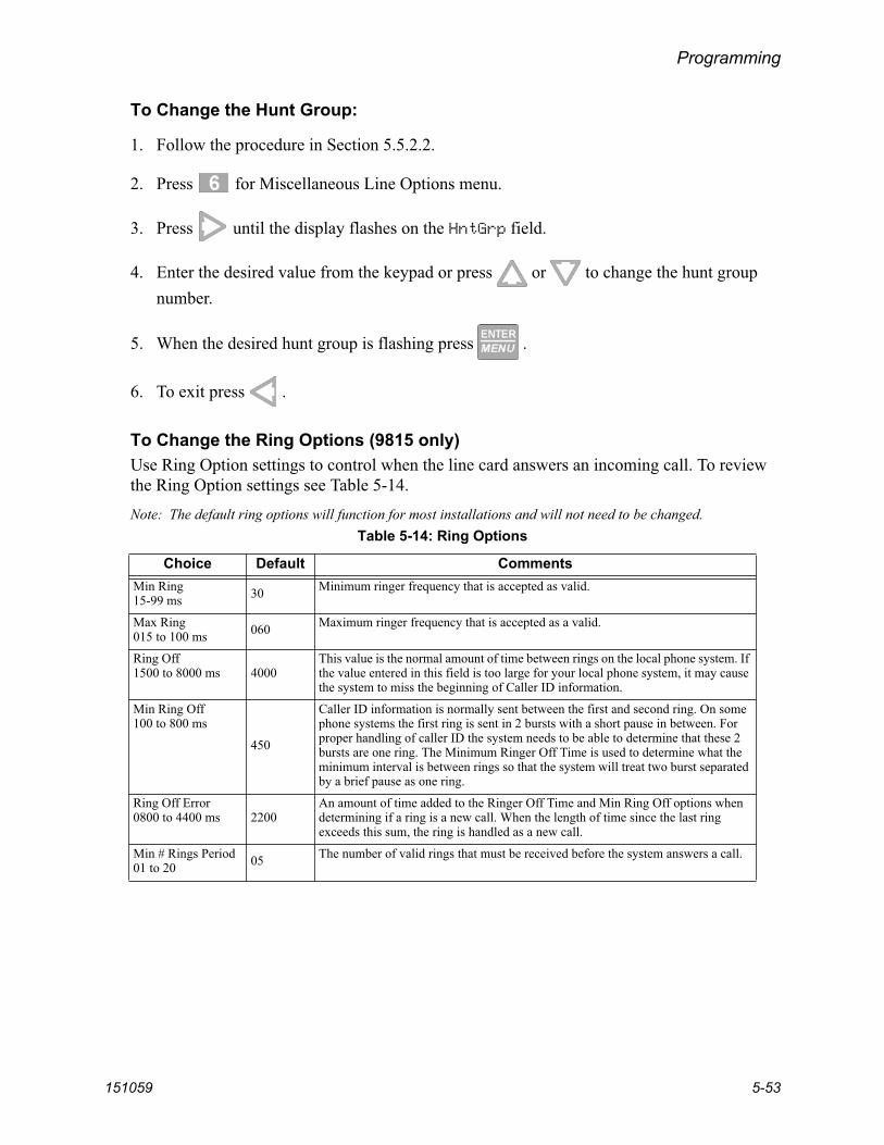
Programming
151059 5-53
To Change the Hunt Group:
1. Follow the procedure in Section 5.5.2.2.
2. Press for Miscellaneous Line Options menu.
3. Press until the display flashes on the HntGrp field.
4. Enter the desired value from the keypad or press or to change the hunt group number.
5. When the desired hunt group is flashing press .
6. To exit press .
To Change the Ring Options (9815 only)Use Ring Option settings to control when the line card answers an incoming call. To review the Ring Option settings see Table 5-14.Note: The default ring options will function for most installations and will not need to be changed.
Table 5-14: Ring Options
Choice Default CommentsMin Ring15-99 ms 30 Minimum ringer frequency that is accepted as valid.
Max Ring015 to 100 ms 060 Maximum ringer frequency that is accepted as a valid.
Ring Off1500 to 8000 ms 4000
This value is the normal amount of time between rings on the local phone system. If the value entered in this field is too large for your local phone system, it may cause the system to miss the beginning of Caller ID information.
Min Ring Off100 to 800 ms
450
Caller ID information is normally sent between the first and second ring. On some phone systems the first ring is sent in 2 bursts with a short pause in between. For proper handling of caller ID the system needs to be able to determine that these 2 bursts are one ring. The Minimum Ringer Off Time is used to determine what the minimum interval is between rings so that the system will treat two burst separated by a brief pause as one ring.
Ring Off Error0800 to 4400 ms 2200
An amount of time added to the Ringer Off Time and Min Ring Off options when determining if a ring is a new call. When the length of time since the last ring exceeds this sum, the ring is handled as a new call.
Min # Rings Period01 to 20 05 The number of valid rings that must be received before the system answers a call.
Model 9500 Central Station Receiver Installation/Operation Manual
5-54 151059
To set ring options:
1. Follow the procedure in Section 5.5.2.2.
2. Press for Miscellaneous Line Options menu.
3. Press until the display flashes on the RingOptions field.
4. Press .
5. Make the desired changes using the arrow keys to navigate and select values.
6. To exit press .
To Change Call Hang Up SettingsUse Call Hang Up setting to control how long the receiver will hold the line before hanging up after a call has ended. See Table 5-10 for more information.
1. Follow the procedure in Section 5.5.2.2.
2. Press for Miscellaneous Line Options menu.
3. Press until the display flashes on the CallHangUp field.
4. Enter the desired value from the keypad or press or to change the setting.
5. To exit press .

Programming
151059 5-55
5.5.2.9 Ademco Auto OptUsed to set up communication with a automation system using Ademco automation protocols.
1. Follow the procedure in Section 5.5.2.2.
2. Press for Ademco Automation Options menu.
3. Press until the display flashes on the desired field.
4. Enter the desired value from the keypad or press or to change the setting.
5. Press .
6. Repeat steps 3 and 4 for each option.
7. To exit press .
5.5.2.10 ITI Options MenuIn this programming location settings particular to an ITI control panel can be set, such as security codes (SCode), date and time setting, and 300 baud negotiation. See Table 5-15 for more information on the ITI Options menu.
Figure 5-16 ITI Options Menu

Model 9500 Central Station Receiver Installation/Operation Manual
5-56 151059
Table 5-15: ITI Options Menu Items
ITI Options Menu Choice Valid Entry Comments
ITI SCode Menu
Default SCode 00000 to 99999 This set the default security code for this line card. Additional security codes can be added to the SCode table (see below).
Add Acct/SCode(up to 20 entries)
Enter control panel 5-digit account No.
00000 to 99999 Enter the 5-digit account number of the ITI control panel that the receiver will be looking for on this line card.
Set or Clear Security Code.
Clear
or
Clear old security code and set to default security code. (See Default SCode above.)
Set If set is chosen an additional menu will appear that allows you to enter the security code you wish to set the panel to.
Security Code 00000 to 99999(Appears only if Set is previously chosen)
Note: If the security code entered here is not presently in the SCode table (see be-low), it will automatically be entered once the line card has successfully communicat-ed with that account.
Edit Acct/SCode 1 to 20 Same as Add Acct/SCode
Edit an account previously programmed into Add Acct/SCode table.
Clear Acct/SCode 1 to 20 Remove an account that was previously programmed into Add Acct/SCode table.
Add SCode Table(up to 20)
00000 to 99999 Adds a new security code to the security code table.
Clear Scode Table 1 to 20 Removes an security code from the SCode table.
Date/Time Flag
Requested The date and time programmed into an ITI control panel will only be updated by the receiver if the control panel requests it.
Always The date and time programmed into an ITI control panel will be updated by the receiver automatically every time the control panel calls into the receiver.
ITI 300 Baud Yes If enabled, the receiver will attempt to negotiate 300 baud communication with ITI panels that support 300 baud communication. See 5.5.2.8 for programming steps.
No
Audio Mode
InstantITI controls that have listen in initialized will preform listen in instantly when the control calls the central station.
One Ring
ITI controls that have listen in initialized will preform listen in after one ring when the control is called, after the control calls the central station.
Dial BackITI controls that have listen in initialized will call a programmed phone number after the control calls the central station.

Programming
151059 5-57
ITI SCode Menu:Some ITI control panels use one of two types of communication locks (phone lock or a central station lock). On the panels using a central station lock, a security code is required during communication. In this programming location a 5-digit central station lock security code can be set.
1. Follow the procedure in Section 5.5.2.2.
2. Press for ITI options menu.
Figure 5-17 ITI SCode Menu
3. Press for ITI SCode (security code) menu.
Choose the desired option (refer to Table 5-15).
4. Press .
5. Enter the necessary field information (see Table 5-15).

Model 9500 Central Station Receiver Installation/Operation Manual
5-58 151059
To Set Date/Time Flag:
1. Follow the procedure in Section 5.5.2.2.
2. Press for ITI options menu.
3. Press for date/time flag menu.
4. Press or to toggle between Requested or Always. See Table 5-15 for descrip-tion.
5. When the desired setting is flashing press . To exit press .
To Enable or Disable ITI 300 Baud Negotiation:
1. Follow the procedure in Section 5.5.2.2.
2. Press for ITI options menu.
3. Press for ITI options menu.
4. Press or to toggle between Yes or No. See Table 5-15 for description.
5. When the desired setting is flashing press . To exit press .
Set the Type of Listen-In Used for ITI Controls:
1. Follow the procedure in Section 5.5.2.2.
2. Press for ITI options menu.
3. Press for Audio Mode menu.
4. Press or to select the desired setting. See Table 5-15 for description.
5. When the desired setting is flashing press . To exit press .

Programming
151059 5-59
5.5.2.11 Line Gain Options Menu (9815 only)The Line Gain Options menu let you set parameters for a 9815 line card.
Figure 5-18 Line Gain Options Menu
Changing the Transmit and Receive Gain
1. Follow the procedure in Section 5.5.2.2.
2. Press for the Line Gain Options menu (see Figure 5-18).
The display Flashes on the Xmit= to change the transmit gain or the Rec= field to change the transmit receive gain.
3. Press or to change the transmit gain option.
4. When the setting is flashing press .
Model 9500 Central Station Receiver Installation/Operation Manual
5-60 151059
Changing the Caller ID (CID) MonitorCaller ID Monitor allows you to select from the following decoding modes:
• Normal (standard) – The detection method is first ring, delay, preamble, marks, and then Caller ID data. Normal is the default.
• Preamble – The Caller ID chip looks for preamble data prior to Caller ID.• DTMF (non-standard) – The system looks for DTMF based Caller ID data.• Marks – The Caller ID chip looks for a Marks signal prior to the Caller ID data.
Note: This option is only applicable when Caller ID has been selected (see page page 52).
1. Follow the procedure in Section 5.5.2.2.
2. Press for the Line Gain Options menu.
3. Press until the display flashes on the Mon= field.
4. Press or to change the CID option.
5. When the setting is flashing press .
Changing the Caller ID (CID) Gain and On Hook GainCaller ID Gain sets the gain of the Caller ID receive logic. On Hook Gain sets the analog receive Caller ID gain prior to line pickup.
Note: These options are only applicable when Caller ID has been selected (see page page 52).
1. Follow the procedure in Section 5.5.2.2.
2. Press for the Line Gain Options menu.
3. To change the CID Gain option, press until the display flashes on the Gain= field, or
press until the display flashes on the OHGain= field.
4. Press or to change the Gain option.
5. When the setting is flashing press .
Programming
151059 5-61
Changing the Ringer ImpedanceRinger Impedance allows the impedance the Caller ID chip presents to the phone line to be set for either High or Synthesize.
Note: This option is only applicable when Caller ID has been selected (see page page 52).
1. Follow the procedure in Section 5.5.2.2.
2. Press for the Line Gain Options menu.
3. Press until the display flashes on the RImp= field.
4. Press or to change the ring impedance option.
5. When the setting is flashing press .
5.5.3 Copy DevicesThe Copy Device option lets you to program a line card to default factory settings established by Silent Knight or copy the programming of an existing line card.
5.5.3.1 To Program the Default Settings Into a Line CardThe Use Defaults option lets you program a line card to default factory settings established by Silent Knight.Warning: This procedure cannot be undone.
1. Enter Program Mode (see Section 5.1).
2. Press to choose Line Device Menu.The display will show <Select Device Type>.
3. Press if the line card is a 9810, and press if the line card is a 9815. If you have only one line card model installed, only that model number will display.
4. Press to select the Copy Device(s) menu.
5. Press to select the Use Defaults menu.
6. Press or until the equal sign highlights the desired line card number.
7. Press the button to toggle to Y (yes) to program this line card to default values.
8. When all line cards you want program to factory defaults are chosen, press .

Model 9500 Central Station Receiver Installation/Operation Manual
5-62 151059
5.5.3.2 Copy the Programming of an Existing Line Card to AnotherThe Copy Existing option is a time saving feature that lets you copy the programming of one line card to one or more installed line cards.Warning: This procedure cannot be undone.
1. Enter Program Mode (see Section 5.1).
2. Press to choose Line Device Menu.The display will show <Select Device Type>.
3. Press if the line card is a 9810, and press if the line card is a 9815. If you have only one line card model installed, only that model number will display.
4. Press to select the Copy Device(s) menu.
5. Press to select the Copy Existing menu.
6. Press or until the equal sign highlights the desired Source line card number.
7. Press .
8. Press or until the equal sign highlights the desired Target line card number.
9. Press the button to toggle to Y (yes) to copy this line card.
10. When all line cards you want copy are chosen, press .
11. Press .

Programming
151059 5-63
5.5.4 Clear DeviceYou can use the Clear Device option to remove a line card from being seen by the receiver.
Figure 5-19 Steps to Clear a Line Card From the Receiver
To Clear or Delete a Line Card From the Receiver:
1. Enter Program Mode (see Section 5.1).
2. Press to choose Line Device Menu.The display will show <Select Device Type>.
3. Press if the line card is a 9810, and press if the line card is a 9815. If you have only one line card model installed, only that model number will display.
4. Press to select the Clear Device menu.
5. Press until the desired line card is highlighted with an equal sign.
6. Press .The display will read <Warning!> LC01 9815 Line Delete Record No
7. Press until Yes is flashing.
8. Press , then press to exit.

Model 9500 Central Station Receiver Installation/Operation Manual
5-64 151059
5.5.5 View DeviceTo view all the line cards in the receiver follow these steps:
1. Enter Program Mode (see Section 5.1).
2. Press to choose Line Device Menu.The display will show <Select Device Type>.
3. Press if the line card is a 9810, and press if the line card is a 9815. If you have only one line card model installed, only that model number will display.
4. Press to select the View Device menu.
5. Press to view line cards.
6. When display shows the list of line cards, press to scroll through the list of line cards to select the desired line card.
7. Press to see device information, including part number and serial number.
8. To exit press .
5.5.6 RollinsTo set this line card to receive calls from Rollins control panels.
1. Enter Program Mode (see Section 5.1).
2. Press to choose Line Device Menu.The display will show <Select Device Type>.
3. Press to select the Rollins menu. The display shows the list of line cards.
4. Press or until the equal sign highlights the desired line card number.
5. Press the button to toggle to Y (yes) to copy this line card.
6. When all line cards for which you want to accept Rollins calls are chosen, press .

Programming
151059 5-65
5.6 User List
The User List option is used to program and store the information on the installers and operators who will operate and maintain the receiver. From this option, you can add, edit, and clear (delete) installers and operators. The receiver supports up to 40 users. Each user is assigned a name, PIN (personal identification number), and a profile.
Figure 5-20 User List Menu Items
Table 5-16 lists the available choices under User List and provides a matrix of choices.Table 5-16: User List Menu Items and Steps
Choice Step 1 Step 2 Step 3 Comments
Add User Enter user name:
1. Use the up or down arrow to move through characters.
2. Press the right arrow to move to next character slot.
3. Press enter key to move to next step.
Enter PIN code:4 digits minimum9 digits maximum
Choose profile level:Operator or Installer
Add user is used to add a new user to the system and enter the user’s PIN and profile information.
Edit User When “Choose User” list appears:
1. Press the down arrow key until the desired user is highlighted with the equal sign.
2. Press enter to move to next step.
Repeat Steps 1-3 under Add User.
Edit user is used to change an existing users profile.
Clear User When “Choose User” list appears:
1. Press the down arrow key until the desired user is highlighted with the equal sign.
2. Press enter to move to clear user from profile list.
Clear user is used to delete a user from the receiver’s memory.
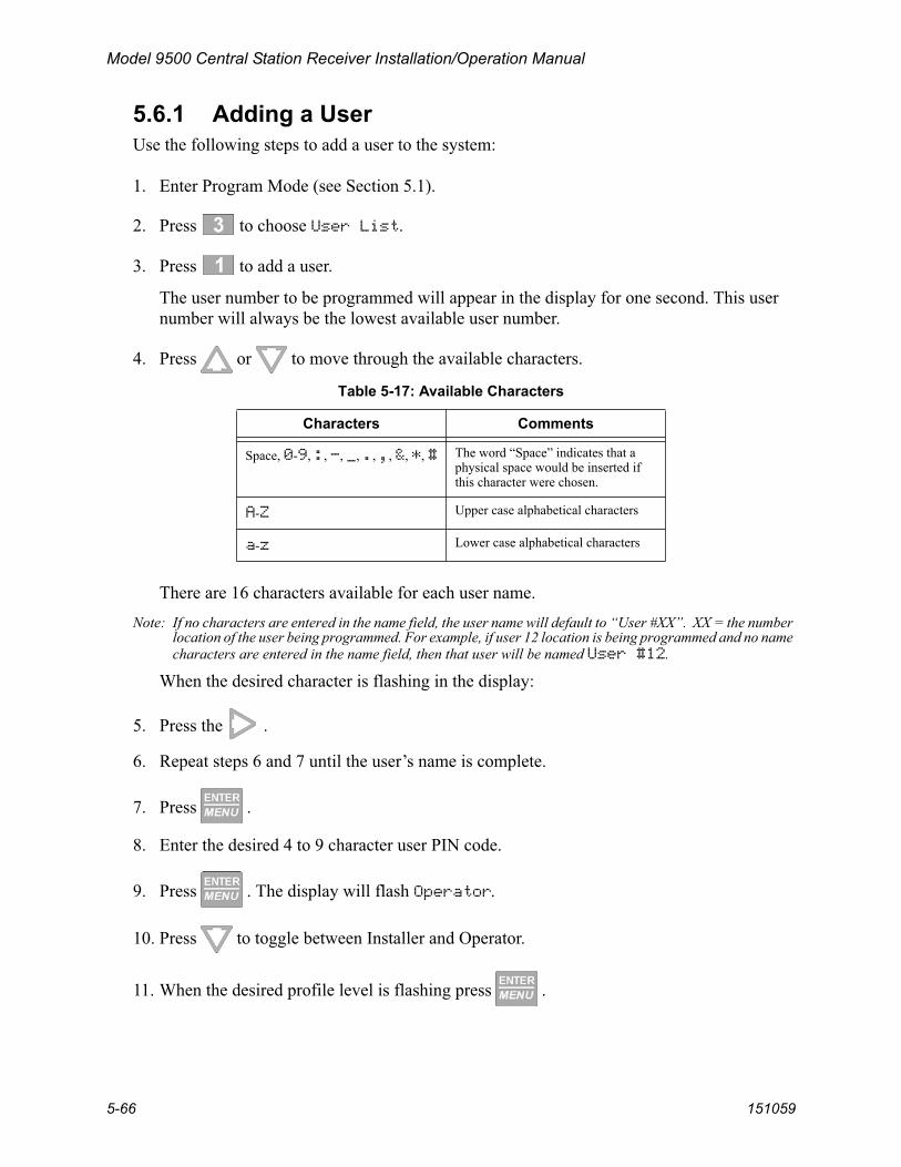
Model 9500 Central Station Receiver Installation/Operation Manual
5-66 151059
5.6.1 Adding a UserUse the following steps to add a user to the system:
1. Enter Program Mode (see Section 5.1).
2. Press to choose User List.
3. Press to add a user.
The user number to be programmed will appear in the display for one second. This user number will always be the lowest available user number.
4. Press or to move through the available characters.
There are 16 characters available for each user name. Note: If no characters are entered in the name field, the user name will default to “User #XX”. XX = the number
location of the user being programmed. For example, if user 12 location is being programmed and no name characters are entered in the name field, then that user will be named User #12.
When the desired character is flashing in the display:
5. Press the .
6. Repeat steps 6 and 7 until the user’s name is complete.
7. Press .
8. Enter the desired 4 to 9 character user PIN code.
9. Press . The display will flash Operator.
10. Press to toggle between Installer and Operator.
11. When the desired profile level is flashing press .
Table 5-17: Available Characters
Characters Comments
Space, 0-9, :, -, _, ., ,, &, *, # The word “Space” indicates that a physical space would be inserted if this character were chosen.
A-Z Upper case alphabetical characters
a-z Lower case alphabetical characters

Programming
151059 5-67
5.6.2 Editing a UserUse the following steps to edit an existing user:
1. Enter Program Mode (see Section 5.1).
2. Press to choose User List.
3. Press to edit a user.
A list of all the users will appear starting with the lowest user number.
4. Press or to move through the user list.
5. When the equal sign highlights the user you wish to edit, press .
6. If you do not want the user name changed, press .
Or
To change the user name, press or to move through the available characters. (See Table 5-17 for list of available characters.)
7. When the name change is complete press .
8. If you do not want the PIN code changed, press .
Or
To change the PIN code enter the desired code (4 to 9 digits in length), then press .
The display will flash the current profile level.
9. Press to toggle between Installer and Operator.
10. When the desired profile level is flashing press .

Model 9500 Central Station Receiver Installation/Operation Manual
5-68 151059
5.6.3 Clearing a User From the ReceiverYou can remove a user from the receiver’s memory at any time using the Clear User option. The Installer and Operator user’s (01 and 02 in the user list) cannot be deleted from the receiver.
Use the following steps to clear or delete a user from the system:
1. Enter Program Mode (see Section 5.1).
2. Press to choose User List.
3. Press to clear (delete) a user.
A list of all the users will appear starting with the lowest user number.
4. Press or to move through the user list.
5. When the equal sign highlights the user you wish to clear press .
The display shows < WARNING ! >Delete Record No
6. Press or to toggle the flashing display to Yes.
7. Press .
5.7 PC Account/Code
The PC Account/Code feature, as shown below, is for factory diagnostics and is not for use in the field by installers.

151059 6-1
Section 6Compatible Reporting Formats
This section lists all the reporting formats that are compatible with the 9500.Table 6-1 shows the formats that the 9500 can decode, handshake frequency format group which accommodates that format (see Section 5.5 for line card programming). Each line card can decode every format listed below, however, a line card can be programmed to prioritize the handshake order in which that line card will communicate.
6.1 Formats By Communication Group.
Table 6-1 shows which formats fit under the general communication groups and the corresponding handshake frequency.
Table 6-1: Formats compatible with the 9500
CommunicationGroup Format Name Description Handshake
Format Group
Tone Burst
SK 4+2 Sends a 4-digit account and a 2-digit alarm code up to four rounds.
1400 Hz
Sescoa 3+1/Franklin 3+1 Sends a 3-digit account and a 1-digit alarm code up to four rounds in a tone burst format. Each digit can be programmed from (0-9). Because there is no standard, this format reports in codes only.
2300 Hz
Radionics 3+1 Checksum Sends a 3-digit account and a 1-digit alarm code and a checksum.
1400 or 2300 Hz
SK 3+1/3+1 Extended Sends a 3-digit account and a 1-digit alarm code up to four rounds (10-40pps). Each block of data (2 rounds). If a second block of data is sent, it will contain the extended information. The account number cannot have repetitive digits (333, 888, etc.).
1400 or 2300 Hz
4+1/4+1 Extended Sends a 4-digit account code and a 1-digit alarm code up to four rounds in a pulse format (10-40pps).
4/1 1400 or 4/1 2300 Hz
Pulse 4+2 sends a 4-digit account code and a 2-digit alarm code. 1400 or 2300 Hz
DTMF
Ademco Contact ID Dual Tone Multiple Frequency. The data is decoded into English account information.
1400_2300 Hz
Ademco Super Fast, Sends a 4-digit account code and a 2-digit alarm code up to 9 events per call.
Acron Touch Tone Sends a 4-digit account code and a 1-digit alarm code. Will send a maximum of 8 events per call.
Ademco Express Sends a 4-digit account code and a 2-digit alarm code with a checksum.
DTMF 4+2 Sends a 4-digit account code and a 2-digit alarm code with a checksum.
FBI 4+3+1 Sends a 4-digit account code, a 3-digit zone code and a 1-digit event code.
1400 or 2300 Hz
Westec Sends a 4-digit account code, a 3-digit Dealer code followed by the event code.
Westec
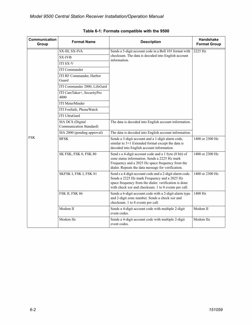
Model 9500 Central Station Receiver Installation/Operation Manual
6-2 151059
FSK
SX-III, SX-IVA Sends a 5-digit account code in a Bell 103 format with checksum. The data is decoded into English account information.
2225 Hz
SX-IVB
ITI SX-V
ITI Commander
ITI RF Commander, Harbor Guard
ITI Commander 2000, LifeGard
ITI CareTaker+, SecurityPro 4000
ITI MeterMinder
ITI FonSafe, PhoneWatch
ITI UltraGard
SIA DCS (Digital Communication Standard)
The data is decoded into English account information.
SIA 2000 (pending approval) The data is decoded into English account information.
BFSK Sends a 3-digit account and a 1-digit alarm code, similar to 3+1 Extended format except the data is decoded into English account information.
1400 or 2300 Hz
SK FSK, FSK 0, FSK 80 Send s a 4-digit account code and a 1 byte (8 bit) of zone status information. Sends a 2225 Hz mark Frequency and a 2025 Hz space frequency from the dialer. Repeats the data message for verification.
1400 or 2300 Hz
SKFSK I, FSK I, FSK 81 Send s a 4-digit account code and a 2-digit alarm code. Sends a 2225 Hz mark Frequency and a 2025 Hz space frequency from the dialer. verification is done with check xor and checksum. 1 to 8 events per call.
1400 or 2300 Hz
FSK II, FSK 86 Sends a 6-digit account code with a 2-digit alarm type and 2-digit zone number. Sends a check xor and checksum. 1 to 8 events per call.
1400 Hz
Modem II Sends a 4-digit account code with multiple 2-digit event codes.
Modem II
Modem IIe Sends a 4-digit account code with multiple 2-digit event codes.
Modem IIe
Table 6-1: Formats compatible with the 9500
CommunicationGroup Format Name Description Handshake
Format Group
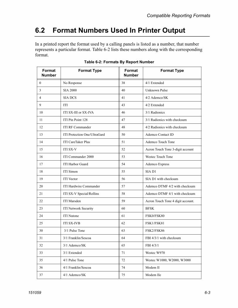
Compatible Reporting Formats
151059 6-3
6.2 Format Numbers Used In Printer Output
In a printed report the format used by a calling panels is listed as a number, that number represents a particular format. Table 6-2 lists these numbers along with the corresponding format.
Table 6-2: Formats By Report Number
FormatNumber
Format Type Format Number
Format Type
0 No Response 38 4/1 Extended
3 SIA 2000 40 Unknown Pulse
4 SIA DCS 41 4/2 Ademco/SK
9 ITI 43 4/2 Extended
10 ITI SX-III or SX-IVA 46 3/1 Radionics
11 ITI Pin Point 128 47 3/1 Radionics with checksum
12 ITI RF Commander 48 4/2 Radionics with checksum
13 ITI Protection One/UltraGard 50 Ademco Contact ID
14 ITI CareTaker Plus 51 Ademco Touch Tone
15 ITI SX-V 52 Acron Touch Tone 3-digit account
16 ITI Commander 2000 53 Westec Touch Tone
17 ITI Harbor Guard 54 Ademco Express
18 ITI Simon 55 SIA D1
19 ITI Vector 56 SIA D1 with checksum
20 ITI Hardwire Commander 57 Ademco DTMF 4/2 with checksum
21 ITI SX-V Special/Rollins 58 Ademco DTMF 4/1 with checksum
22 ITI Marsden 59 Acron Touch Tone 4 digit account.
23 ITI Network Security 60 BFSK
24 ITI Nutone 61 FSK0/FSK80
25 ITI SX-IVB 62 FSK1/FSK81
30 3/1 Pulse Tone 63 FSK2/FSK86
31 3/1 Franklin/Sescoa 64 FBI 4/3/1 with checksum
32 3/1 Ademco/SK 65 FBI 4/3/1
33 3/1 Extended 71 Westec W970
35 4/1 Pulse Tone 72 Westec W1000, W2000, W3000
36 4/1 Franklin/Sescoa 74 Modem II
37 4/1 Ademco/SK 75 Modem IIe

Model 9500 Central Station Receiver Installation/Operation Manual
6-4 151059
6.3 Using Contact ID Format
If you are receiving Contact ID format on your 9500 receiver you must use SK Expanded automation protocol. The 9000 automation protocol does not support Contact ID reporting format.
!WARNING!
Important!Due to the increasing number of formats a single line can accept and the wide variety of manufacturer’s specifications for handshake/acknowledgement tones required for their digital dialers to communicate, Silent Knight strongly recommends the following for handshake tone order.
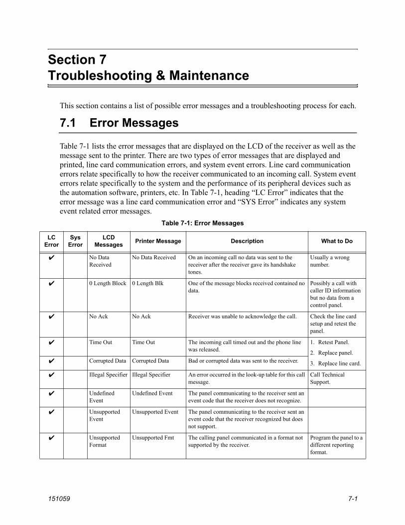
151059 7-1
Section 7Troubleshooting & Maintenance
This section contains a list of possible error messages and a troubleshooting process for each.
7.1 Error Messages
Table 7-1 lists the error messages that are displayed on the LCD of the receiver as well as the message sent to the printer. There are two types of error messages that are displayed and printed, line card communication errors, and system event errors. Line card communication errors relate specifically to how the receiver communicated to an incoming call. System event errors relate specifically to the system and the performance of its peripheral devices such as the automation software, printers, etc. In Table 7-1, heading “LC Error” indicates that the error message was a line card communication error and “SYS Error” indicates any system event related error messages.
Table 7-1: Error Messages
LCError
SysError
LCDMessages Printer Message Description What to Do
No Data Received
No Data Received On an incoming call no data was sent to the receiver after the receiver gave its handshake tones.
Usually a wrong number.
0 Length Block 0 Length Blk One of the message blocks received contained no data.
Possibly a call with caller ID information but no data from a control panel.
No Ack No Ack Receiver was unable to acknowledge the call. Check the line card setup and retest the panel.
Time Out Time Out The incoming call timed out and the phone line was released.
1. Retest Panel.
2. Replace panel.
3. Replace line card.Corrupted Data Corrupted Data Bad or corrupted data was sent to the receiver.
Illegal Specifier Illegal Specifier An error occurred in the look-up table for this call message.
Call Technical Support.
UndefinedEvent
Undefined Event The panel communicating to the receiver sent an event code that the receiver does not recognize.
UnsupportedEvent
Unsupported Event The panel communicating to the receiver sent an event code that the receiver recognized but does not support.
UnsupportedFormat
Unsupported Fmt The calling panel communicated in a format not supported by the receiver.
Program the panel to a different reporting format.

Model 9500 Central Station Receiver Installation/Operation Manual
7-2 151059
CommunicationError
CommunicationError, Panel Requested Re-send
There was a communication error between the panel and the receiver and the receiver asked the panel to re-send the message.
If it continues test the panel.
Possible Incomplete
Possible Incomplete Call
The receiver missed information in the call sequence.
Retest the panel.
System Power Up
System Power Up Indicated that the receiver powered up.
ExpanderTrouble
Expander Trouble Trouble with a device connected to the SBUS. Check the connection of that device on the SBUS. If connection OK replace SBUS device (line cards and touchpads).
Expander Trbl Rst
Expander Trouble Restore
The trouble condition of a SBUS device was corrected.
AC Trouble AC Trouble AC power failure. Check AC outlet and AC power cord.
AC Trouble Rst AC Trouble Restore AC power was restored.
Battery Low Restore
Battery Low Restore The backup battery power supply trouble has been corrected.
Restores at 12VDC after a low battery condition.
Battery Low Battery Low The backup battery is checked continually every second. This message would be displayed if the backup battery were set to “Battery Bkp”. See Section 5.4.4. Indicates a low battery when the voltage drops to 10.2 VDC or lower.
Check battery cables. If they are OK replace backup battery.
Local Program Begin
Local Program Begin User #
This message indicates the time a system “installer” entered program mode.
Local Program End
Local Program End User #
This message indicates the time a system “installer” exited program mode.
Local Program Fail
Local Program Fail User #
The receiver will stay in program mode for 15 minutes without any activity, then it will time out and go back to normal mode. This message indicates that an installer entered programming and did not exit programming before it timed out.
Listen-in End Listen-in End A listen-in session completed
Listen-in Begin Listen-in Begin A listen-in session started.
System Date Changed
System Date Changed User #
An installer changed the system date.
System Time Changed
System Time Changed User #
An installer changed the system time.
Table 7-1: Error Messages
LCError
SysError
LCDMessages Printer Message Description What to Do

Troubleshooting & Maintenance
151059 7-3
Msg Queue Full Message Queue Full Messages can be sent to automation computer, a printer or can be manually acknowledged. If one or more of these devices does not respond to messages being sent or manually acknowledged, the message queue will fill up. When the message queue is full the receiver will no longer accept incoming calls.
Verify that messages are acknowledged to any printers, automation software, and while in manual mode.
Msg Queue Full restore
Message Queue Full restore
Indicates that the message queue full error has been corrected.
Main Computer Trbl
Main Computer Trouble
A communication problem exists between the automation software and the receiver.
Check cable connections. Verify that the port is configured properly.
Main Computer Rst
Main Computer Restore
The communication error between the receiver and the automation software has been corrected.
Bkup Computer Trbl
Bkup Computer Trouble
A communication problem exists between the backup automation software and the receiver.
Check cable connections. Verify that the port is configured properly.
Bkup Computer Rst
Bkup Computer Restore
The communication error between the receiver and the backup automation software has been corrected.
Main Prn Off Trbl
Main Printer Off Line The port programmed as the primary printer port is off line.
Check cable connections. Verify that the port is configured properly. Check power to printer.
Main Prn Paper Out
Main Printer Paper Out
The port programmed as the primary printer port is out of paper.
Replace paper in printer.
Main Prn Restore
Main Printer Restore The error on the primary printer has been corrected.
Bkup Prn Off Trbl
Bkup Printer Off Line
The port programmed as the backup printer port is off line.
Check cable connections. Verify that the port is configured properly. Check power to printer.
Bkup Prn Paper Out
Bkup Printer Paper Out
The port programmed as the backup printer port is out of paper.
Replace paper in printer.
Bkup Prn Restore
Bkup Printer Restore The error on the backup printer has been corrected.
DC Input Low Rst
DC Input Low Restore
The backup DC power supply trouble has been corrected.
Restores at 12VDC after a low battery condition.
Table 7-1: Error Messages
LCError
SysError
LCDMessages Printer Message Description What to Do

Model 9500 Central Station Receiver Installation/Operation Manual
7-4 151059
DC Input Low DC Input Low The backup battery is checked continually every second. This message would be displayed if the backup battery setting were set to “DC Bkp”. See Section 5.4.4. Indicates a low when the voltage drops to 10.2 VDC or lower.
Check the connection to the DC power supply. Verify the output from DC power supply.
Msg Que > Warning
Message Queue Warning
When the message queue reaches the programmed level mark, this message is given as a pre-warning to “Message Queue Full”. See Section 5.4.5.1 to program the % level at which the receiver will indicate the warning.
Verify that messages are acknowledged to any printers, automation software, and while in manual mode.
Msg Que < Warning
Message Queue Warning Restore
This message is given when the message queue drops below the programmed level after a message queue warning indication has displayed. See Section 5.4.5.2 to program the % level.
LC Run in ROM
Linecard Running ROM Code
The line card is not running the application code. Replace the line card.
Line Fault Line Fault The phone line voltage has dropped below the threshold voltage as programmed. (See Section 5.5.2.5.)
Check phone line outlet and phone cord.
Line Fault Restore
Line Fault Restore Phone line voltage has been restored to normal parameters.
Line Card Deleted
Line Card Record Deleted
A line card has been deleted.
Line Card Added
Line Card Record Added
A line card has been added.
User Log In User Log In: User # A user has logged on to the receiver.
User Log Out User Log Out: User # A user has logged off of the receiver.
Table 7-1: Error Messages
LCError
SysError
LCDMessages Printer Message Description What to Do

Troubleshooting & Maintenance
151059 7-5
7.2 Troubleshooting Process
Before you call Technical Support you may be able to solve the problem yourself by following these procedures.
1. Verify that a problem exists.
2. Check Fault Status.
This can be done by pressing the . If the system fault LED in on the display will read:
Press the down arrow to view fault messages.
3. Check the manual for suggestions or solutions.
4. Check connections.
5. Isolate the problem. Remove other devices that may be interfering.
6. Try swapping devices to isolate the problem.
7. Try to replace the problematic device.
8. Document the failures and the steps used to resolve them.

Model 9500 Central Station Receiver Installation/Operation Manual
7-6 151059
7.3 Replacing the 9500 Fuse
If the AC Power light is off or flashing and the 9500 has 120 VAC of power, check the 9500 fuse. If the fuse needs to be replaced, follow the steps below.
1. Remove power from the 9500.
2. Locate the fuse cap on the back of the 9500 as shown in Figure 7-1.
Figure 7-1 Replacing the Power Supply Fuse
3. Using a flathead screw driver, gently turn the fuse holder counterclockwise to remove.
4. Remove the existing fuse from the fuse cap and replace with a 2.5A slow blow fuse.
5. Reinsert the fuse cap in the 9500 and gently turn clockwise until it is seated.

Troubleshooting & Maintenance
151059 7-7
7.4 Safe Mode
Safe mode can be used to reset User #01 access code back to default of 9500 regardless of its present setting.
For Example, if the code for the installer (User #01) is lost and additional programming is required the receiver can be restarted in safe mode to return User #01 to an access code of 9500.
Follow these steps to initiate Safe Mode and default User code #01:
1. Follow the steps in Section 4.6.7 to restart the receiver.Note: All messages must be acknowledged before a system restart procedure can be performed. If all messages
are not acknowledged, cycle the receiver’s power to restart the system. If the power is cycled all unacknowledged messages will be lost.
2. When the display shows Model 9500 ReceiverSilent Knight
3. Press the button, then the button.
The display will read Safe Mode Activated
4. Press .
5. Enter the default Installer code or 9500.
7.5 Updating the Receiver Software
Silent Knight will continue to test reporting formats with the9500 receiver. As additional reporting formats become available it may be necessary to update your receiver. This can be done from your own PC, using a null modem cable (see Figure 3-14 and Figure 3-15). Any software upgrades will be sent to you on a 3.5 inch floppy disk and will come with down-loading instructions.

Model 9500 Central Station Receiver Installation/Operation Manual
7-8 151059

151059 A-1
App
endi
x A
Prog
ram
min
g Q
uick
Ref
eren
ce C
hart
Tabl
e A
-1: P
rogr
amm
ing
Qui
ck C
hart
Prog
ram
Mod
e O
ptio
nsC
hoic
esC
hoic
esC
hoic
esC
hoic
esC
omm
ents
Gen
eral
Opt
ions
Ope
ratio
n M
ode
Man
ual
See
Sect
ion
4.5
for d
escr
iptio
n of
mod
es o
f ope
ratio
n. S
ee a
lso
Sect
ion
5.4.
1.A
utom
atic
Log
Onl
y
Dis
play
Opt
ions
Lang
uage
Engl
ish
See
Sect
ion
5.4.
2 fo
r det
ails
.es
paño
lN
ot a
vaila
ble
at th
is ti
me.
Tim
e Fo
rmat
AM
PM12
hou
r clo
ck. S
ee S
ectio
n 5.
4.2.
2 fo
r det
ails
.24
Hr
24 h
our c
lock
. See
Sec
tion
5.4.
2.2
for d
etai
ls.
Dat
e Fo
rmat
M\D
\YSe
e Se
ctio
n 5.
4.2.
3 fo
r det
ails
.M
= m
onth
, D =
day
, Y =
yea
r.D
·M·Y
Y-M
-D
Day
Lig
ht S
avin
g
Yes/
No
See
Sect
ion
5.4.
2.4
for d
etai
ls.
Star
t Mon
thJa
n –D
ecSt
art W
eek
1st –
4th
and
Las
tEn
d M
onth
Jan
–Dec
End
Wee
k1s
t – 4
th a
nd L
ast
ITI O
ptio
ns
Atte
mpt
sYe
s or N
oSe
e Se
ctio
n 5.
4.2.
5A
ffect
s prin
ter a
nd L
CD
out
put o
nly.
CPU
Tim
eYe
s or N
oC
PU T
ype
Yes o
r No
Pane
l Rev
Yes o
r No
Arm
ing
Leve
lYe
s or N
o
Form
at C
onfig
.FS
K1
Cod
eIf
“En
glis
h” is
sele
cted
then
the
prin
ter a
nd L
CD
out
put f
or c
alls
of
thes
e fo
rmat
s will
be
text
des
crip
tions
. If “
Cod
e” is
sele
cted
th
en th
e pr
inte
r and
LC
D o
utpu
t for
cal
ls o
f the
se fo
rmat
s will
be
the
Cod
e an
d Zo
ne n
umbe
rs. S
ee S
ectio
n 5.
4.2.
6 fo
r ste
p-by
-ste
p in
stru
ctio
ns.
Engl
ish

Model 9500 Central Station Receiver Installation/Operation Manual
A-2 151059
Gen
eral
Opt
ions
(c
ont.)
Dis
play
Opt
ions
(con
t.)Fo
rmat
Con
fig.
(con
t.)
BSF
K
Cod
eIf
“En
glis
h” is
sele
cted
, the
prin
ter a
nd L
CD
out
put w
ill b
e te
xt.
If “
Cod
e” is
sele
cted
then
the
prin
ter a
nd L
CD
will
dis
play
the
SIA
cod
es fo
llow
ed b
y zo
ne o
r oth
er in
form
atio
n. S
ee S
ectio
n 5.
4.2.
6 fo
r ste
p-by
-ste
p in
stru
ctio
ns.
Engl
ish
This
opt
ion
only
affe
cts t
he S
K E
xpan
ded
auto
mat
ion
prot
ocol
ou
tput
. If “
Engl
ish”
is se
lect
ed e
ach
even
t will
be
sent
to th
e au
tom
atio
n as
two
SIA
eve
nts;
the
first
with
the
two
digi
t Gro
up
num
ber a
nd th
e se
cond
with
the
thre
e di
git I
D n
umbe
r. If
“C
ode”
is
sele
cted
, eac
h ev
ent i
s sen
t as e
leve
n di
gits
; tw
o di
gits
M
essa
ge ty
pe, o
ne-d
igit
Even
t Qua
lifie
r, th
ree-
digi
t Eve
nt C
ode,
tw
o-di
git G
roup
Num
ber,
and
thre
e-di
git I
D n
umbe
r. Se
e Se
ctio
n 5.
4.2.
6 fo
r ste
p-by
-ste
p in
stru
ctio
ns.
SIA
Cod
eIf
“En
glis
h” is
sele
cted
then
the
prin
ter a
nd L
CD
out
put f
or c
alls
of
thes
e fo
rmat
s will
be
text
des
crip
tions
. If “
Cod
e” is
sele
cted
th
en th
e pr
inte
r and
LC
D o
utpu
t for
cal
ls o
f the
se fo
rmat
s will
be
the
Cod
e an
d Zo
ne n
umbe
rs. S
ee S
ectio
n 5.
4.2.
6 fo
r ste
p-by
-ste
p in
stru
ctio
ns.
Engl
ish
CID
Cod
eIf
“En
glis
h” is
sele
cted
, the
prin
ter a
nd L
CD
out
put w
ill b
e te
xt.
If “
Cod
e” is
sele
cted
then
the
prin
ter a
nd L
CD
will
dis
play
the
SIA
cod
es fo
llow
ed b
y zo
ne o
r oth
er in
form
atio
n. S
ee S
ectio
n 5.
4.2.
6 fo
r ste
p-by
-ste
p in
stru
ctio
ns.
Engl
ish
This
opt
ion
only
affe
cts t
he S
K E
xpan
ded
auto
mat
ion
prot
ocol
ou
tput
. If “
Engl
ish”
is se
lect
ed e
ach
even
t will
be
sent
to th
e au
tom
atio
n as
two
SIA
eve
nts;
the
first
with
the
two
digi
t Gro
up
num
ber a
nd th
e se
cond
with
the
thre
e di
git I
D n
umbe
r. If
“C
ode”
is
sele
cted
, eac
h ev
ent i
s sen
t as e
leve
n di
gits
; tw
o di
gits
M
essa
ge ty
pe, o
ne-d
igit
Even
t Qua
lifie
r, th
ree-
digi
t Eve
nt C
ode,
tw
o-di
git G
roup
Num
ber,
and
thre
e-di
git I
D n
umbe
r. Se
e Se
ctio
n 5.
4.2.
6 fo
r ste
p-by
-ste
p in
stru
ctio
ns.
PULS
E0
.. 9
If “
0 ..
9”
is se
lect
ed h
exad
ecim
al d
igits
B th
roug
h F
are
forc
ed
to 0
as i
n th
e w
ay th
e 90
00 re
ceiv
er d
oes i
t, or
if “
0 ..
F” is
se
lect
ed d
igits
are
sent
as i
s.0
.. F
SK90
00Pa
cked
Each
dat
a pa
cket
to th
e au
tom
atio
n co
ntai
ns a
sing
le (u
npac
ked)
or
mul
tiple
(pac
ked)
eve
nts.
See
Sect
ion
5.4.
2.6.
Unp
acke
dA
CR
ON
Zero
and
Spa
ceIf
set t
o Sp
ace
then
zer
o ch
arac
ters
are
tran
slat
ed a
s a sp
ace,
if se
t to
Zer
o th
en a
zer
o is
sent
as a
zer
o. S
ee S
ectio
n 5.
4.2.
6.H
ISPE
EDSA
I and
HiS
peed
If se
t to
SIA
then
an
even
t is t
rans
late
d to
SIA
form
at w
hen
sent
to
the
auto
mat
ion
com
pute
r. Se
e Se
ctio
n 5.
4.2.
6.V
irtua
lPr
inte
rIf
set t
o Pr
inte
r, lin
e ca
rd sl
ot n
umbe
rs a
re se
nt to
SK
9000
au
tom
atio
n an
d pr
inte
r.A
llIf
set t
o A
ll, v
irtua
l lin
e nu
mbe
rs a
re se
nt to
SK
9000
aut
omat
ion
and
prin
ter.
Tabl
e A
-1: P
rogr
amm
ing
Qui
ck C
hart
Prog
ram
Mod
e O
ptio
nsC
hoic
esC
hoic
esC
hoic
esC
hoic
esC
omm
ents

Programming Quick Reference Chart
151059 A-3
Gen
eral
Opt
ions
(c
ont.)
Dis
play
Opt
ions
(con
t.)H
old
last
eve
nt
Yes
If Y
es, L
CD
will
dis
play
the
last
ack
now
ledg
ed e
vent
inst
ead
of
the
date
/tim
e di
spla
y in
the
auto
mod
e. In
man
ual m
ode
the
disp
lay
will
show
the
olde
st u
nack
now
ledg
ed e
vent
. See
Sec
tion
5.4.
2.6.
No
Com
mun
icat
ion
(con
t.)
Port
Func
tions
Com
1U
nuse
d/A
utom
atio
n/Pr
inte
r/R
ules
for P
ort C
onfig
urat
ion:
Func
tions
in B
rack
ets [
] ap
pear
onl
y if
“Aut
omat
ion”
is se
lect
ed
for C
om1.
Func
tions
in {
} a
ppea
r onl
y if
“Pr
inte
r” is
sele
cted
in C
om1
or
Par.
A fu
nctio
n m
ay b
e se
lect
ed o
nly
once
in th
e 3
ports
(onl
y on
e pr
inte
r, on
ly o
ne D
iag,
etc
.).A
ll po
rts m
ay b
e co
nfig
ured
“U
nuse
d”.
See
Sect
ion
5.4.
3.1.
Com
2U
nuse
d/[A
uto
Bkp
]/[A
uto
Bkp
Pr
n]/{
Prin
t Bkp
}/D
iag/
Prin
ter
Par (
Para
llel)
Unu
sed/
[Aut
o B
kp]/P
rinte
r/Dia
g
Com
Por
t1
Bau
d38
400,
192
00, 9
600,
720
0,48
00,
2400
, 120
0, 6
00, 3
00, 1
10Se
e Se
ctio
n 5.
4.3.
2 fo
r det
ails
.
D (#
Dat
a B
its)
8, 7
S (#
Sto
p bi
ts)
1 or
2P
(Par
ity)
Even
, Odd
, No,
Po
rt M
onito
rYe
s, N
oF
(Flo
w C
ontro
l)H
dwr,
Sftw
r, N
one
Init
Str
(Ini
tializ
atio
n St
ring)
Ente
r ASC
II c
hara
cter
s for
the
Esca
pe c
omm
and
sequ
ence
de
sire
d. F
or e
xam
ple:
Set
the
page
size
or n
umbe
r of l
ines
per
pa
ge fo
r a se
rial p
rinte
r.C
om P
ort2
Sam
e as
Com
1
Par P
ort
Edit
Init
Strin
gEn
ter o
r edi
t an
Esca
pe co
mm
and
sequ
ence
. For
exam
ple:
Set
the
page
size
or n
umbe
r of l
ines
per
pag
e fo
r a p
rinte
r.C
lear
Init
Strin
g
Aut
omat
ion
Cfg
.
Form
at
SK E
XP,
SK
9000
, SIA
CIS
, C
APS
,FB
I I22
0, A
DEM
685
, ITI
Com
p,
ITI G
en
See
Sect
ion
5.4.
3.5
for d
etai
ls.
Hex
Y (y
es)
This
feat
ure
is o
nly
avai
labl
e if
SK 9
000
auto
mat
ion
prot
ocol
is
sele
cted
.N
(no)
Hea
rtbea
tY
(yes
)N
(no)
Tim
e (o
f hea
rtbea
t)10
-600
seco
nds
Ack
tim
eout
1 to
120
seco
nds
Tabl
e A
-1: P
rogr
amm
ing
Qui
ck C
hart
Prog
ram
Mod
e O
ptio
nsC
hoic
esC
hoic
esC
hoic
esC
hoic
esC
omm
ents

Model 9500 Central Station Receiver Installation/Operation Manual
A-4 151059
Gen
eral
Opt
ions
(c
ont.)
Com
mun
icat
ion
(con
t.)
Ann
unci
ator
Con
figur
atio
n
Prin
ter
Yes o
r No
Yes =
will
ann
unci
ate
if an
eve
nt, t
roub
le o
r fau
lt co
nditi
on
occu
rs.
No
= no
ann
unci
atio
n if
an e
vent
, tro
uble
or f
ault
cond
ition
oc
curs
.D
efau
lt fo
r all
optio
ns: Y
es.
See
Sect
ion
5.4.
3.6.
*Li
sten
In o
ptio
n m
ust b
e se
t to
No
for U
L in
stal
latio
ns.
Bkp
Prin
ter
Yes o
r No
Aut
o C
omp
Yes o
r No
Bkp
Aut
o C
omp
Yes o
r No
Bat
tery
Yes o
r No
Dev
ice
Yes o
r No
Line
Fau
ltYe
s or N
oA
C P
ower
Yes o
r No
Buf
fer F
ull
Yes o
r No
List
en In
Yes o
r No
Cal
l Pen
ding
Yes o
r No
Aux
Rel
ay C
fgO
ptio
ns th
e sa
me
as A
nnun
ciat
or C
onfig
urat
ion.
See
Sect
ion
5.4.
3.7.
*Li
sten
In o
ptio
n m
ust b
e se
t to
No
for U
L in
stal
latio
ns.
Syst
em O
ptio
ns
Bat
tery
Bac
kup
Cfg
No
Bat
tery
Bkp
No
char
ging
cur
rent
app
lied
to b
atte
ry c
ircui
t. R
ecei
ver w
ill n
ot
test
bat
tery
out
put o
r giv
e tro
uble
ann
unci
atio
ns. D
efau
lt. S
ee
Sect
ion
5.4.
4.1.
DC
Bkp
No
char
ging
cur
rent
app
lied
to b
atte
ry c
ircui
t. Ty
pica
lly u
sed
for
syst
ems t
hat u
se a
UPS
(uni
nter
rupt
ed p
ower
supp
ly) f
or b
acku
p ba
ttery
pow
er. S
ee S
ectio
n 5.
4.4.
1.B
atte
ry B
kpC
harg
ing
curr
ent a
pplie
d to
bat
tery
circ
uit.
See
Sect
ion
5.4.
4.1.
Rec
eive
r ID
No.
01-9
9D
efau
lt: 0
1. S
ee S
ectio
n 5.
4.4.
2.
Bad
Dat
a B
lock
s
Strip
Bad
An
indi
cato
r is s
ent t
o th
e au
tom
atio
n co
mpu
ter t
hat i
ndic
ates
a
bad
data
blo
ck w
as re
ceiv
ed. D
efau
lt.
See
Sect
ion
5.4.
4.3
Send
Bad
Sam
e as
Stri
p D
ata
exce
pt th
e ba
d da
ta b
lock
is se
nt w
ith th
e in
dica
tor.
See
Sect
ion
5.4.
4.3
Aux
iliar
y R
elay
N
orm
al S
tate
Off
Off=
Dee
nerg
ized
. Def
ault.
On
= En
ergi
zed
See
Sect
ion
5.4.
4.4.
Ener
gize
d
Clo
ck S
ourc
e
60 H
zR
ecei
ver c
lock
runs
on
60H
z A
C p
ower
inpu
t. Se
e Se
ctio
n 5.
4.4.
5
50 H
zR
ecei
ver c
lock
runs
on
50H
z A
C p
ower
inpu
t. Se
e Se
ctio
n 5.
4.4.
5.
Int
Rec
eive
r clo
ck ru
ns o
n in
tern
al c
ryst
al. U
se in
are
as w
here
AC
lin
e fr
eque
ncy
is n
ot d
epen
dabl
e. S
ee S
ectio
n 5.
4.4.
5.
Tabl
e A
-1: P
rogr
amm
ing
Qui
ck C
hart
Prog
ram
Mod
e O
ptio
nsC
hoic
esC
hoic
esC
hoic
esC
hoic
esC
omm
ents
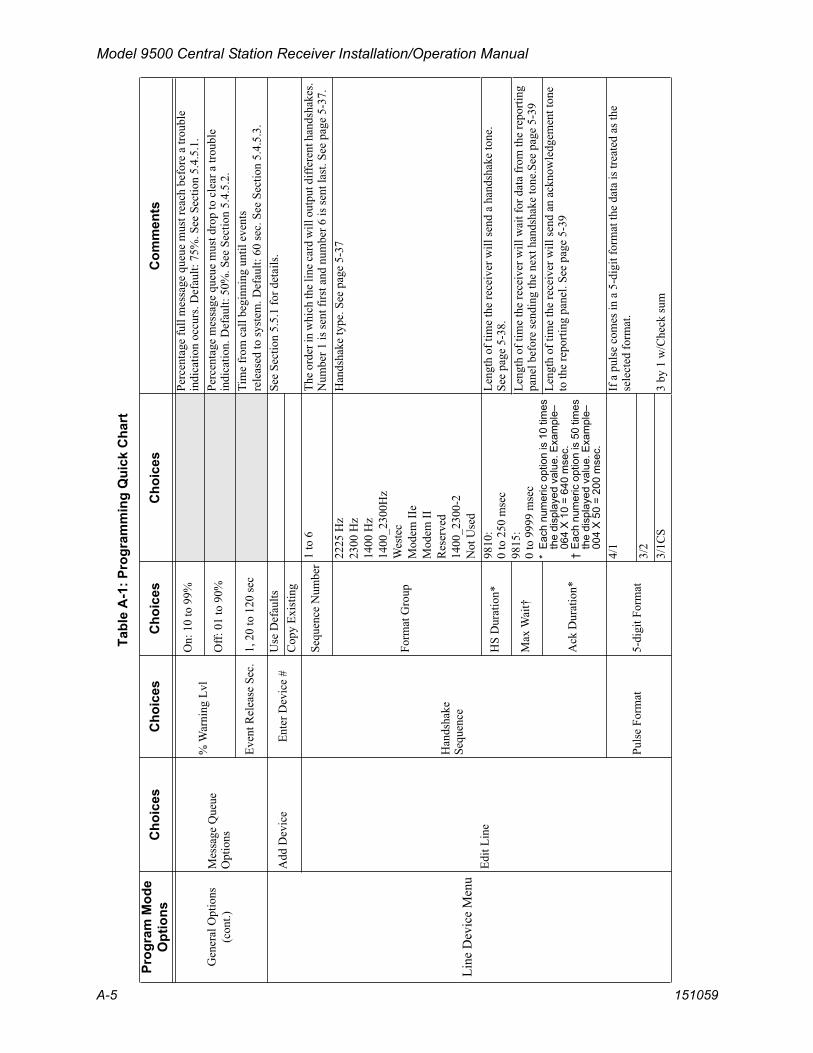
Model 9500 Central Station Receiver Installation/Operation Manual
A-5 151059
Gen
eral
Opt
ions
(c
ont.)
Mes
sage
Que
ue
Opt
ions
% W
arni
ng L
vlO
n: 1
0 to
99%
Perc
enta
ge fu
ll m
essa
ge q
ueue
mus
t rea
ch b
efor
e a
troub
le
indi
catio
n oc
curs
. Def
ault:
75%
. See
Sec
tion
5.4.
5.1.
Off:
01
to 9
0%Pe
rcen
tage
mes
sage
que
ue m
ust d
rop
to c
lear
a tr
oubl
e in
dica
tion.
Def
ault:
50%
. See
Sec
tion
5.4.
5.2.
Even
t Rel
ease
Sec
.1,
20
to 1
20 se
cTi
me
from
cal
l beg
inni
ng u
ntil
even
tsre
leas
ed to
syst
em. D
efau
lt: 6
0 se
c. S
ee S
ectio
n 5.
4.5.
3.
Line
Dev
ice
Men
u
Add
Dev
ice
Ente
r Dev
ice
#U
se D
efau
ltsSe
e Se
ctio
n 5.
5.1
for d
etai
ls.
Cop
y Ex
istin
g
Edit
Line
Han
dsha
keSe
quen
ce
Sequ
ence
Num
ber
1 to
6Th
e ord
er in
whi
ch th
e lin
e car
d w
ill o
utpu
t diff
eren
t han
dsha
kes.
Num
ber 1
is se
nt fi
rst a
nd n
umbe
r 6 is
sent
last
. See
pag
e 5-
37.
Form
at G
roup
2225
Hz
2300
Hz
1400
Hz
1400
_230
0Hz
Wes
tec
Mod
em II
eM
odem
IIR
eser
ved
1400
_230
0-2
Not
Use
d
Han
dsha
ke ty
pe. S
ee p
age
5-37
HS
Dur
atio
n*98
10:
0 to
250
mse
c98
15:
0 to
999
9 m
sec
*E
ach
num
eric
opt
ion
is 1
0 tim
es
the
disp
laye
d va
lue.
Exa
mpl
e–06
4 X
10
= 64
0 m
sec.
†E
ach
num
eric
opt
ion
is 5
0 tim
es
the
disp
laye
d va
lue.
Exa
mpl
e–00
4 X
50
= 20
0 m
sec.
Leng
th o
f tim
e th
e re
ceiv
er w
ill se
nd a
han
dsha
ke to
ne.
See
page
5-3
8.
Max
Wai
t†Le
ngth
of t
ime
the
rece
iver
will
wai
t for
dat
a fr
om th
e re
porti
ng
pane
l bef
ore
send
ing
the
next
han
dsha
ke to
ne.S
ee p
age
5-39
Ack
Dur
atio
n*
Leng
th o
f tim
e th
e re
ceiv
er w
ill se
nd a
n ac
know
ledg
emen
t ton
e to
the
repo
rting
pan
el. S
ee p
age
5-39
Puls
e Fo
rmat
5-di
git F
orm
at
4/1
If a
pul
se c
omes
in a
5-d
igit
form
at th
e da
ta is
trea
ted
as th
e se
lect
ed fo
rmat
.3/
23/
1CS
3 by
1 w
/Che
ck su
m
Tabl
e A
-1: P
rogr
amm
ing
Qui
ck C
hart
Prog
ram
Mod
e O
ptio
nsC
hoic
esC
hoic
esC
hoic
esC
hoic
esC
omm
ents

Model 9500 Central Station Receiver Installation/Operation Manual
A-6 151059
Line
Dev
ice
Men
u(c
ont.)
Edit
Line
(c
ont.)
Puls
e Fo
rmat
(con
t.)
6-di
git F
orm
at
4/2
If a
pul
se c
omes
in a
6-d
igit
form
at th
en th
e da
ta w
ill th
en b
e tre
ated
as t
he se
lect
ed fo
rmat
.3/
2CS
3 by
2 w
/Che
ck su
m4/
1CS
4 by
1 w
/Che
ck su
mTi
meo
ut (I
nter
-di
git T
m [m
s])
300
ms t
o 2
Sec.
This
feat
ure
sele
cts t
he ti
me
perio
d be
twee
n da
ta b
lock
s. If
000
0 is
sele
cted
then
the
rece
iver
will
use
an
auto
mat
ic a
lgor
ithm
.A
ck/E
ven
(Ack
on
Eve
n R
ound
)Ye
sSe
lect
this
opt
ion
if th
e 14
00 o
r 230
0 H
z fo
rmat
requ
ires a
Ack
to
ne o
n ev
en ro
unds
.N
oPa
rt (P
artia
lly
Exte
nded
)Ye
sSe
lect
this
opt
ion
if yo
u ha
ve m
ultip
le e
xten
ded
data
blo
cks f
or
3/1
or 4
/1 fo
rmat
s.N
o
Line
Opt
ions
Dire
ctY
(Yes
)Y
= d
edic
ated
or d
irect
con
nect
pho
ne li
ne.
N =
use
d fo
r sta
ndar
d ph
one
lines
. See
pag
e 5-
41 fo
r mor
e in
form
atio
n.N
o (N
o)
Num
ber o
f Rin
gs
000-
255
Num
ber o
f rin
gs th
e lin
e ca
rd n
eeds
to re
ceiv
e be
fore
it w
ill
answ
er a
cal
l. It
is re
com
men
ded
that
num
ber o
f rin
gs is
not
set
high
er th
an 0
05. I
f Cal
ler I
D is
turn
ed o
n, se
t to
002
(see
pa
ge 5
-52
for m
ore
info
rmat
ion
on th
e C
alle
r ID
opt
ion)
. See
pa
ge 5
-42
for m
ore
info
rmat
ion
on N
umbe
r of R
ings
.O
n tim
e1-
255
in 5
0ms p
erio
ds98
10 li
ne c
ard
only
. See
pag
e 5-
42 fo
r mor
e in
form
atio
n.O
ff tim
e1-
255
in 5
0ms p
erio
ds98
10 li
ne c
ard
only
. See
pag
e 5-
43 fo
r mor
e in
form
atio
n.
dB L
evel
Lo (L
ow)
9810
line
car
d on
ly. S
elec
t the
db
leve
l of t
he h
ands
hake
and
ac
know
ledg
e to
nes.
Hi (
Hig
h)M
d (M
ediu
m)
Cou
ntry
Cod
eSe
e pa
ge 5
-44
9815
line
car
d on
ly. S
ome
Cou
ntry
Cod
e se
lect
ions
supp
ort
mul
tiple
cou
ntrie
s. Se
e pa
ge 5
-44
for d
etai
led
list.
Thre
shol
d1-
15 in
2.0
VD
C st
eps
See
page
5-4
5.Fa
ult D
etec
t (S
ampl
e)0-
255
sec
- 981
00-
90 se
c - 9
815
See
page
5-4
5.
Tabl
e A
-1: P
rogr
amm
ing
Qui
ck C
hart
Prog
ram
Mod
e O
ptio
nsC
hoic
esC
hoic
esC
hoic
esC
hoic
esC
omm
ents

Model 9500 Central Station Receiver Installation/Operation Manual
A-7 151059
Line
Dev
ice
Men
u(c
ont.)
Edit
Line
(c
ont.)
List
en In
List
en M
ode
Not
Use
dSe
e pa
ge 5
-46
for m
ore
info
rmat
ion.
Mus
t not
be
used
in U
L in
stal
latio
ns.
Com
mon
PBX
Acc
ount
Lis
t
Add
up
to 2
0 ac
coun
ts.
See
page
5-4
9.Se
e pa
ge 5
-49.
See
page
5-4
9.PB
X S
tring
edi
tO
nly
avai
labl
e if
PBX
is se
lect
ed in
Lis
ten
Mod
e. S
ee p
age
5-47
.Ti
meo
ut0-
255
See
page
5-4
8.
Acc
ount
Lis
tA
dd A
ccou
ntSe
e pa
ge 5
-48.
Edit
Acc
ount
Cle
ar A
ccou
nt
Trap
Lis
tA
dd A
ccou
ntEn
ter A
ccou
nt #
See
page
5-5
0 th
roug
h pa
ge 5
-51.
Edit
Acc
ount
Cho
ose
Acc
ount
Cle
ar A
ccou
ntC
hoos
e A
ccou
nt
Mis
c. L
ine
Opt
ions
Echo
Sup
pres
s
Y (Y
es)
Out
puts
a 2
seco
nd 2
025H
z to
ne to
dis
able
ech
o su
ppre
ssio
n eq
uipm
ent t
hat m
ay in
terf
ere
with
mod
em fo
rmat
s. Se
e pa
ge 5
-52
N (N
o)
Cal
ler I
D
Yes
The
Cal
ler I
D in
form
atio
n w
ill o
nly
be se
nt o
n in
com
ing
call
mes
sage
s tha
t con
tain
no
data
. If t
he c
all m
essa
ge c
onta
ins a
ny
data
(val
id o
r inv
alid
) no
Cal
ler I
d in
form
atio
n w
ill b
e ou
tput
. Se
e pa
ge 5
-52.
No
Bill
ing
Del
ayY
(Yes
)In
itiat
es a
2 se
cond
del
ay a
t the
star
t of e
ach
call
befo
re th
e ha
ndsh
ake
dela
y.N
(No)
See
page
5-5
2 fo
r mor
e in
form
atio
n.
Hun
t Gro
up00
-99
Allo
ws m
ultip
le li
ne c
ards
to re
port
unde
r the
sam
e gr
oup
num
ber t
o th
e au
tom
atio
n so
ftwar
e.R
ing
Opt
ions
Min
Rin
g98
15 li
ne c
ard
only
. See
pag
e 5-
53.
Max
Rin
gR
ing
Off
Min
Rin
g O
ffR
ing
Off
Erro
rM
in #
Rin
gs P
erio
d
Cal
l Han
g U
pM
ax n
umbe
r of s
econ
ds th
e lin
e ca
rd w
ill st
ay o
ff ho
ok fo
r a c
all.
Hel
ps p
reve
nt a
run
away
pan
el fr
om m
onop
oliz
ing
the
phon
e lin
e. S
ee p
age
5-54
.
Tabl
e A
-1: P
rogr
amm
ing
Qui
ck C
hart
Prog
ram
Mod
e O
ptio
nsC
hoic
esC
hoic
esC
hoic
esC
hoic
esC
omm
ents

Model 9500 Central Station Receiver Installation/Operation Manual
A-8 151059
Line
Dev
ice
Men
u(c
ont.)
Edit
Line
(c
ont.)
Ade
mco
Aut
o O
pt.
BFS
K A
utoO
utH
/SU
sed
to se
tup
com
mun
icat
ion
with
a a
utom
atio
n sy
stem
usi
ng
AD
EMC
O 6
85 o
r CA
PS.
See
Sect
ion
5.5.
2.9.
4/2
3/1
Res
tore
Out
3/1
H/S
4/2
Aut
o O
utH
/SN
or
FBI P
rinte
r Out
S/Fa
stLA
R30
0
Puls
e Ex
tend
edEx
tN
o Ex
t
Exte
nd O
utH
/S4/
2
ITI O
ptio
ns M
enu
ITI S
Cod
e M
enu
Def
ault
SCod
eU
sed
in c
omm
unic
atio
n lo
ckin
g on
ITI p
anel
s.A
dd A
cct/S
Cod
eSe
e Se
ctio
n 5.
4.2.
5. a
nd S
ectio
n 5.
5.2.
10.
Edit
Acc
t/SC
ode
Cle
ar A
cct/S
Cod
eA
dd S
Cod
e Ta
ble
Cle
ar S
Cod
e Ta
ble
Dat
e/Ti
me
Flag
Req
uest
edA
lway
s
ITI 3
00 B
aud
Yes
If e
nabl
ed, t
he re
ceiv
er a
ttem
pts t
o ne
gotia
te 3
00 b
aud
com
mun
icat
ion
with
ITI p
anel
s tha
t sup
port
300
baud
. See
Se
ctio
n 5.
5.2.
10.
No
Aud
io M
ode
Inst
ant
Sele
ct th
e ty
pe o
f lis
ten
in th
at w
ill b
e pe
rfor
med
for I
TI c
ontro
l pa
nels
. See
Sec
tion
5.5.
2.10
.O
ne R
ing
Dia
l Bac
k
Line
Gai
n O
pt
Tran
smit
Gai
n-3
to 1
4 dB
9815
line
car
d on
ly. S
ets l
ine
trans
mit
and
line
rece
ive
gain
. See
Se
ctio
n 5.
5.2.
11.
Rec
eive
Gai
n0
to 1
2 db
CID
Mon
itor
Nor
m, P
rear
m, D
TMF,
or M
arks
Thes
e op
tions
onl
y ap
ply
if th
e C
alle
r ID
opt
ion
is u
sed.
See
Se
ctio
n 5.
5.2.
11 fo
r inf
orm
atio
n on
the
Line
Gai
n O
ptio
ns a
nd
page
5-5
2 fo
r inf
orm
atio
n on
the
Cal
ler I
D o
ptio
n.C
ID G
ain
-6 to
7 d
BO
n H
ook
Gai
n2
to 7
dB
Rin
ger I
mpe
dH
I or S
Y
Tabl
e A
-1: P
rogr
amm
ing
Qui
ck C
hart
Prog
ram
Mod
e O
ptio
nsC
hoic
esC
hoic
esC
hoic
esC
hoic
esC
omm
ents

Model 9500 Central Station Receiver Installation/Operation Manual
A-9 151059
Line
Dev
ice
Men
u(c
ont.)
Cop
y D
evic
e(s)
Use
Def
aults
Cho
ose
Line
ca
rd(s
) #
Cho
ose
Line
car
d(s)
# th
at y
ou w
ish
to b
e pr
ogra
mm
ed to
fact
ory
defa
ults
.
Cop
y Ex
istin
gC
hoos
e Li
ne c
ard
# of
Sou
rce
Line
C
ard
Cho
ose
the
targ
et li
ne c
ard(
s) #
.C
opy
the
prog
ram
min
g of
one
line
car
d (s
ourc
e) a
nd p
aste
it in
to
one
or se
vera
l (ta
rget
) lin
e ca
rds.
Cle
ar D
evic
eLi
ne C
ard
#Se
e Se
ctio
n 5.
5.4
for d
etai
ls.
Vie
w D
evic
eLi
ne C
ard
#Se
e Se
ctio
n 5.
5.5
for d
etai
ls.
Rol
lins
Line
Car
d #(
s)Se
e Se
ctio
n 5.
5.6
for d
etai
ls.
Use
r Lis
t
Add
Use
r
Use
r Nam
eU
p to
16
char
acte
rs.
See
Sect
ion
5.6
for d
etai
ls.
Use
r Cod
e4-
9 di
gits
Use
r Pro
file
Inst
alle
r/Ope
rato
r
Edit
Use
rLi
st o
f use
rsU
ser n
ame,
cod
e an
d pr
ofile
Cle
ar U
ser
List
of u
sers
Tabl
e A
-1: P
rogr
amm
ing
Qui
ck C
hart
Prog
ram
Mod
e O
ptio
nsC
hoic
esC
hoic
esC
hoic
esC
hoic
esC
omm
ents

Model 9500 Central Station Receiver Installation/Operation Manual
A-10 151059

Silent Knight Fire Product Warranty and Return Policy
Limited WarrantySilent Knight warrants that the products of its manufacture shall be free from defects in materials or workmanship for five years from the manufacturing date code on the printed circuit board, if such goods have been properly installed, are subject to normal proper use, and have not been modified in any manner whatsoever. Upon return of the defective product, Silent Knight will at its sole discretion, either repair or replace, at no cost, such goods as may be of defective material or workmanship. Customers outside the United States are to return products to their distributor for repair.
Silent Knight SHALL NOT UNDER ANY CIRCUMSTANCES BE LIABLE FOR ANY INCIDENTAL OR CONSEQUENTIAL DAMAGES ARISING FROM LOSS OF PROPERTY OR OTHER DAMAGE OR LOSSES OWING TO THE FAILURE OF Silent Knight PRODUCTS BEYOND THE COST OF REPAIR OR REPLACEMENT OF ANY DEFECTIVE PRODUCTS.
Silent Knight MAKES NO WARRANTY OF FITNESS OR MERCHANTABILITY AND NO OTHER WARRANTY, ORAL OR WRITTEN, EXPRESS OR IMPLIED, BEYOND THE 18 MONTH WARRANTY EXPRESSLY SPECIFIED HEREIN.
IMPORTANT: Silent Knight products should be tested weekly to ensure complete and proper operation and proper input and output connections.
Repair and RA Procedure• All products that are returned to Silent Knight for credit or repair require a RA (Return
Authorization) number. Call Silent Knight Customer Service at 800-446-6444 or 763-493-6435 between 8:00 A.M. and 4:45 P.M. CST, Monday through Friday to obtain a return authorization number. Silent Knight Technical Support is available at 800-328-0103 between 8:00 A.M. and 6:00 P.M. CST, Monday through Friday.
• RA number must be prominently displayed on the outside of the shipping box. See return address example under Advanced Replacement Policy.
• Include a packing slip that has the RA number, a content list, and a detailed description of the problem should be included with each return.
• All products returned to Silent Knight must be sent freight pre-paid. After product is pro-cessed, Silent Knight will pay for shipping product back to customer via UPS ground.
• Do not return batteries. Silent Knight has the authority to determine if a product is repair-able. Products that are deemed un-repairable will be returned to the customer.

• Product that is returned that has a board date code more than five years from date of man-ufacture will be repaired and the customer will be assessed the standard Silent Knight repair charge for that model.
• Repairs and returns should be sent to:
Silent Knight
Attn: Repair Department
7550 Meridian Circle Suite 100
Maple Grove, MN 55369-4927
RA Number:___________________
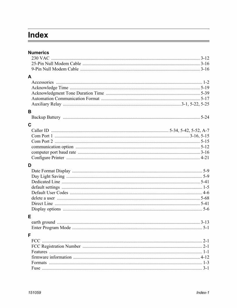
151059 Index-1
Index
Numerics230 VAC ................................................................................................................................ 3-1225-Pin Null Modem Cable ..................................................................................................... 3-169-Pin Null Modem Cable ....................................................................................................... 3-16
AAccessories .............................................................................................................................. 1-2Acknowledge Time ................................................................................................................ 5-19Acknowledgment Tone Duration Time ................................................................................. 5-39Automation Communication Format ..................................................................................... 5-17Auxiliary Relay ......................................................................................................3-1, 5-22, 5-25
BBackup Battery ...................................................................................................................... 5-24
CCaller ID ..................................................................................................... 5-34, 5-42, 5-52, A-7Com Port 1 ....................................................................................................................3-16, 5-15Com Port 2 ............................................................................................................................. 5-15communication option ........................................................................................................... 5-12computer port baud rate ......................................................................................................... 3-16Configure Printer ................................................................................................................... 4-21
DDate Format Display ................................................................................................................ 5-9Day Light Saving ..................................................................................................................... 5-9Dedicated Line ....................................................................................................................... 5-41default settings ......................................................................................................................... 1-5Default User Codes .................................................................................................................. 4-6delete a user ........................................................................................................................... 5-68Direct Line ............................................................................................................................. 5-41Display options ........................................................................................................................ 5-6
Eearth ground ........................................................................................................................... 3-13Enter Program Mode ................................................................................................................ 5-1
FFCC .......................................................................................................................................... 2-1FCC Registration Number ....................................................................................................... 2-1Features .................................................................................................................................... 1-1firmware information ............................................................................................................. 4-12Formats .................................................................................................................................... 1-3Fuse .......................................................................................................................................... 3-1

151059 Index-2
GGeneral Options ....................................................................................................................... 5-3Grounding .............................................................................................................................. 3-13
HHandshake Duration .............................................................................................................. 5-38Handshake Sequence ............................................................................................................. 5-37Handshake Wait ..................................................................................................................... 5-39Heartbeat .......................................................................................................................5-18, 5-19Hold Last Event ..................................................................................................................... 5-11
IInitialization string (Init string) .............................................................................................. 5-16ITI Computer Interface format ............................................................................................... 5-20ITI Formats ............................................................................................................................ 5-21ITI Generic ............................................................................................................................. 5-20ITI Panels ............................................................................................................................... 5-21ITI Security Code ................................................................................................................... 5-57
LLanguage Display .................................................................................................................... 5-8LCD ......................................................................................................................................... 4-3LCD Contrast ........................................................................................................................... 4-4LED .......................................................................................................................................... 4-3Line card ................................................................................................................................ 5-31Line Options .......................................................................................................................... 5-41Line Voltage ............................................................................................................................ 3-1Listen-in ................................................................................................................................. 4-29log off ....................................................................................................................................... 4-7log on ....................................................................................................................................... 4-6Log Record ............................................................................................................................ 5-21
MMain Menu ............................................................................................................................... 4-9Main Menu Option Items by Profile ........................................................................................ 4-5Maneuver Around in Program Mode ....................................................................................... 5-2Maneuver Through Main Menu ............................................................................................. 4-10Manual (Common) Listen-In ................................................................................................. 4-29model number ........................................................................................................................ 4-12
NNormal mode ........................................................................................................................... 4-8
OOn-board Annunciator ........................................................................................................... 5-22Operation mode .................................................................................................................5-4, 5-5

151059 Index-3
PPBX string .............................................................................................................................. 4-30Phone Line Sample Rate ........................................................................................................ 5-45PIN ........................................................................................................1-5, 4-6, 5-65, 5-66, 5-67Port function .......................................................................................................................... 5-14Power Up ................................................................................................................................. 4-5Print a Test Page .................................................................................................................... 4-20Print Call History ................................................................................................................... 4-17print menu .............................................................................................................................. 4-15Print Report ............................................................................................................................ 4-17Print System Configuration ................................................................................................... 4-19Print System History .............................................................................................................. 4-18printer cable ............................................................................................................................. 3-8Program Menu ....................................................................................................................... 4-22Programming ........................................................................................................................... 5-1Programming Choices .............................................................................................................. 5-3Programming Fields ................................................................................................................. 5-2
RReceiver ID ...................................................................................................................4-12, 5-24Ring Off Time ........................................................................................................................ 5-43Ring On Time ........................................................................................................................ 5-42Ring Threshold Voltage ......................................................................................................... 5-45Rings ...................................................................................................................................... 5-42
SSet Time & Date .................................................................................................................... 4-13software date code ................................................................................................................. 4-12software revision .................................................................................................................... 4-12Supervisory Character ............................................................................................................ 5-21System History ....................................................................................................................... 4-11System Info ............................................................................................................................ 4-12System Options ...................................................................................................................... 5-23
TTesting ................................................................................................................................... 4-30Threshold ............................................................................................................................... 5-45Time Format Display ............................................................................................................... 5-8Touchpad Buttons .................................................................................................................... 4-2
UUser List ................................................................................................................................. 5-65

151059 Index-4

7550 Meridian CircleMaple Grove, MN 55369-4927763-493-64551-800-328-0103Fax: 763-493-6475
© 2006 Silent Knight